

Page 1
Comfort
BREEZE
TM
READ AND SAVE THESE INSTRUCTIONS
CB300/CB300S
Flow-Through Evaporative Humidier
Trion® | www.trioniaq.com
Page 2

Installation, Operation, & Maintenance Manual
READ AND SAVE THESE INSTRUCTIONS
LIRE ET CONSERVER CES INSTRUCTIONS
TABLE OF CONTENTS
1. Warranty Statement .................................................................................................................................3
2. Safety Warnings .......................................................................................................................................3
3. Introduction ..............................................................................................................................................4
3.1 Basic Operation .............................................................................................................................. 4
3.2 Specications Table ........................................................................................................................4
3.3 What’s in the Box ...........................................................................................................................4
4. Installation ................................................................................................................................................ 4
4.1 Clearances ..................................................................................................................................... 4
4.2 Mounting......................................................................................................................................... 4
4.3. Plumbing ........................................................................................................................................6
4.4. Electrical/Wiring ..............................................................................................................................7
4.4.1 Wiring CB300 (without water saving controls)....................................................................7
4.4.2 Wiring CB300S (with ComfortSmart Technology) .............................................................. 7
5. Operation .................................................................................................................................................7
5.1 Preliminary Checkout .....................................................................................................................7
5.2 Starting and Stopping the humidier ..............................................................................................7
5.3 End Of Season Decommissioning..................................................................................................8
6. Maintenance/Troubleshooting .................................................................................................................. 8
6.1 Pad Replacement ........................................................................................................................... 8
6.2 Control Board Faults & Reset.........................................................................................................8
6.3 Troubleshooting Chart .................................................................................................................... 9
6.4 Exploded View/Parts List ................................................................................................................10
2 www.trioniaq.com
Comfort
BREEZE
TM
Model CB300
Page 3
Installation, Operation, & Maintenance Manual
1. Warranty
Humidier 5-Year Limited Warranty
This limited warranty covers Trion Residential Type Humidiers, exclud-
ing duct work, wiring and installation. Trion warrants that all new Trion
humidiers are free from defects in material and workmanship under
normal, non-commercial use and service. Trion will remedy any covered defects if they appear within 60 months from the date of original
installation & subject to the terms and conditions of this Limited 5-Year
Warranty stated below:
1. THIS LIMITED 5-YEAR WARRANTY is granted by Trion Customer
Service, 101 McNeill Road, Sanford, NC 27330.
2. This warranty shall extend only to any non-commercial owner who
has purchased the residential humidier other than for purposes
of resale.
3. All components are covered by this limited warranty except ex-
pendable items, such as evaporative pads, media lter pads and
nozzles.
4. If, within the warranty period, any Trion residential humidier unit or
component requires service it must be performed by a competent
heating and/or air conditioning contractor (preferably the installing
contractor). Trion will not pay shipping charges, or labor charges to
remove or replace such defective parts or components. If the part
or component is found by inspection to contain such defective material and workmanship it will be either repaired or exchanged free
of charge at Trion’s option, and returned freight collect.
5. In order to obtain the benets of this limited 5-year warranty, the
owner must notify the dealer or distributor of any defect within 30
days of its discovery. If after reasonable time you have not received
an adequate response from the dealer or distributor, notify in writ-
ing to Trion Customer Service 101 McNeill Road, Sanford, NC
27330, or call 1-800-884-0002 or email customerservice@trioniaq.
com Humidiers which have been installed or become part of real
estate cannot be returned. Trion will receive, freight prepaid, only
removable parts or components of such defective humidiers.
6. This limited warranty does not apply to any part or component that
is damaged in transit or in handling, has been subject to misuse,
neglect or accident; has not been installed, operated and serviced
according to Trion’s instructions; has been operated beyond the
factory rated capacity; or altered in any such way that its performance is affected. There is no warranty due to neglect, alteration
or ordinary wear and tear. Trion’s liability is limited to replacement
of defective parts or components and does not include the payment of the cost of labor charges to remove or replace such defective components or parts.
7. Trion will not be responsible for loss of use of any product; loss
of time, inconvenience, or any other indirect, incidental or consequential damages with respect to person or property, whether as a
result of breach of warranty, neglect or otherwise. SOME STATES
DO NOT ALLOW THE EXCLUSION OR LIMITATION OF INCIDENTAL OR CONSEQUENTIAL DAMAGES, SO THE LIMITA-
TION OR EXCLUSION IN THE PRECEDING SENTENCE MAY
NOT APPLY TO YOU.
8. THIS WARRANTY GIVES YOU SPECIFIC RIGHTS, AND YOU
MAY ALSO HAVE OTHER RIGHTS WHICH VARY FROM STATE
TO STATE.
9. Any warranty by Trion of merchantability, tness for use or any oth-
er warranty (express, implied or statutory), representation or guarantee other than those set forth herein, shall expire at the expiration date of this express limited warranty. SOME STATES DO NOT
ALLOW LIMITATIONS ON HOW LONG AN IMPLIED WARRANTY
LASTS, SO THE LIMITATION IN THE PRECEDING SENTENCE
MAY NOT APPLY TO YOU.
10. Trion reserves the right to make changes in the design and material
of its products without incurring any obligation to incorporate such
changes in units completed on the effective date of such change.
2. Safety & Warnings
!
DANGER
RISK OF ELECTRIC SHOCK
Before cleaning, servicing, or parts replacement, the unit must
be disconnected from all sources of electricity.
!
WARNING
Improper installation, adjustment, alteration, service, or main-
tenance may cause property damage, injury, or death. This
appliance must be installed according to these instructions.
Read these instructions thoroughly before installing or servic-
ing the unit.
!
CAUTION
Read these instructions thoroughly before installing this unit.
Check data label and verify electrical specications agree
with those at the point of installation.
!
WARNING
Failure to install this unit in a position that is level and plumb
may impair the unit’s ability to drain if an overow condition
presents itself. Damage to personal property may also result.
!
WARNING
Installation in freezing conditions can result in unit failure.
Damage to personal property may also result.
!
WARNING
A drain pan should be installed under the unit and any supply
water / drain connections to prevent damage to property in the
event of a water leak or faulty operation.
!
CAUTION
Trion recommends that this humidier be installed by a
trained HVAC professional. Do not connect the unit to the
power source until the installation is complete. A thorough
checkout of the unit installation should be completed before
operating the unit. Failure to follow these directions may void
the manufacturer’s original warranty.
!
WARNING
Electrical power to the furnace must be disconnected before
proceeding. Serious injury or death may result.
Comfort
BREEZE
TM
Model CB300
www.trioniaq.com
3
Page 4
Installation, Operation, & Maintenance Manual
3. Introduction
The benets of a properly humidied environment (35-50%
Relative Humidity) are many. They include both personal com-
fort as well as the preservation of furniture, draperies, carpets,
wooden oors and cabinets, paintings, pianos, etc. Your home
can be more comfortable at a lower temperature (i.e.: 68° F)
at 30-40% Relative Humidity (RH) than at 71° to 72° F with-
out controlled humidity. Since every degree of temperature
setback represents about 3% of your heating costs, this can
possibly represent a signicant annual savings. During the heating season, cold air inltrates the home and must be heated.
When heated, this air dries out and greatly increases its
capacity to hold more moisture. By using a humidier, a
source of water is provided to satisfy this increased mois-
ture holding capability, rather than having it drawn from our
body surface and the surrounding furnishings in the home.
3.1 Basic Operation
Your Comfort
operates on the principles of evaporation. Water is introduced
to an evaporator pad as warm air from the duct is circuilated
through the pad. The warm air evaporates the water and the relative humidity of the air increases. Any excess water is passed
to the drain. CB300S units are equipped with a ComfortSmart
controller which acts to minimize the amount of water that may
ow to the drain by adjusting the total water ow to the humidier.
Setting the humidistat in the recommended range of 30-40%
relative humidity assures automatic humidity control during the
heating season. A lower setting may be necessary to prevent
condensation on windows during the coldest part of the winter.
An electronic humidistat is supplied with CB300S units that can
automatically adjust the setpoint as the outdoor temperature
falls.
Minimal action is needed to turn the humidier off for the summer months. Simply rotate the damper to the closed position
and lower the humidistat setpoint.
BREEZE
TM
ow-through evaporative humidier
Voltage(Amps) 24 VAC(0.8A)
Unit Dimensions 14.13"W x 10"D x 19"H
Water Supply Connection 1/4” OD Tubing
Drain Water Connection 1/2” ID Tubing
Duct Opening 9.75”W x 13.13”H
Shipping Weight 11.25 Lbs.
Operating Weight 8.5 Lbs.
Approvals ETL
4. Installation
Prior to installing this product:
• Read the instructions carefully and completely to ensure
safe operation. Failure to follow the instructions could lead
to damage to the product or cause a hazardous condition.
• Check the ratings given on the product to make sure it is
suitable for your application.
Remember to select a location that is readily accessible for periodic inspection, cleaning, and service. The following table on
page 5 indicates the minimum allowable installation clearances.
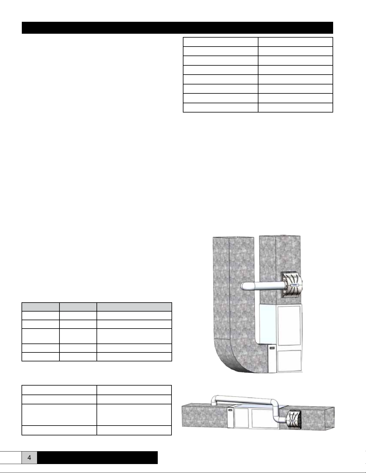
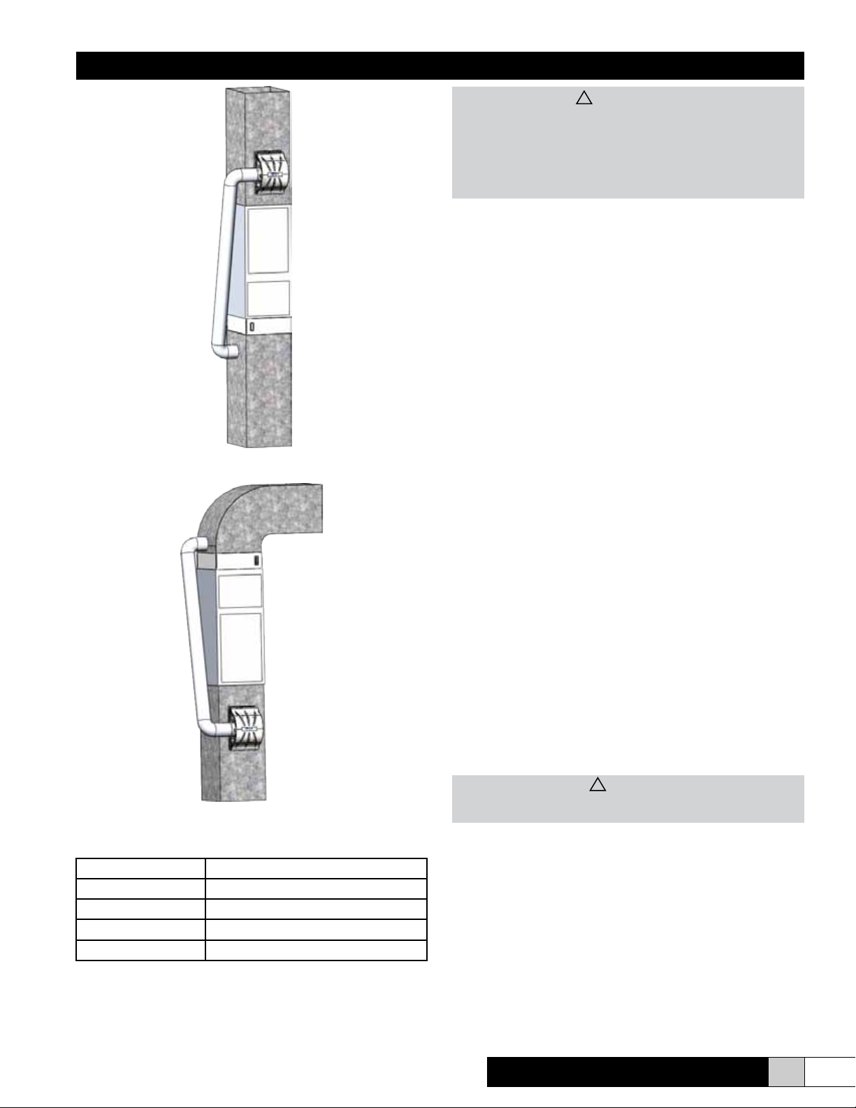
The following illustrations show some of the possible installation congurations and where the humider should be installed.
This humidier may be installed on the supply or return side of
the furnace. Operation with the warmest possible air will maxi-
mize output capacity. Installation on the supply duct after the
furnace discharge is recommended.
3.2 “What’s In The Box?”
CB300 CB300S Description
X X Humidier
X Mech. Humidistat (CB300)
X
X Transformer (CB300 only)
X X Parts Bag
Electronic Humidistat
(CB300S)
3.3 Unit Specications
Type of Unit Bypass Evaporative
Mounting Warm Air Supply/Return Duct
Capacity (GPD) 22.0 GPD @ 140 °F
17.0 GPD @ 120 °F
14.5 GPD @ 100 °F
Water Supply 20-100 PSI
4 www.trioniaq.com
Upow - Side Return
Comfort
Horizontal Flow
BREEZE
TM
Model CB300
Page 5
Installation, Operation, & Maintenance Manual
!
CAUTION
Trion recommends that this humidier be installed by a
trained HVAC professional. Do not connect the unit to the
power source until the installation is complete. A thorough
checkout of the unit installation should be completed before
operating the unit. Failure to follow these directions may void
the manufacturer’s original warranty.
4.2 Mounting
The ComfortBREEZE CB300/CB300S humidier may be
mounted directly to the warm air supply duct or the return duct
of your HVAC system. Certain conditions must be met to ensure proper unit operation. Refer to the following list.
• Ensure that the duct surface is reinforced, if necessary, to
allow the unit to remain level and plumb.
• Ensure that the humidier has adequate clearance to allow
for the removal and replacement of the evaporator pad.
• When installing the humidier in an attic or above a ceiling,
a drain tray must be installed under the unit as a precau-
tionary measure to prevent water damage from occuring if
a leak develops.
• The recommended humidistat range is 30-40% relative humidity. If condensation occurs on windows, the humidistat
Upow - Bottom Return
setting must be lowered to prevent condensation damage.
• DO NOT install the humidier where freezing temperatures
may occur.
• DO NOT install the humidier where it interferes with the
furnace access panels.
• DO NOT install the humidier close to a ue pipe. Intense
heat may damage the humidier.
• DO NOT mount the humidier in the jacket of a cased
coil. It is preferable to mount the humidier immediately
downstream of the cased coil, if present. Ensure that the
humidier does not interfere with the coil ends.
• DO NOT mount the humidier in a furnace jacket.
• DO NOT install on gravity hot air systems.
• DO NOT connect a hot water supply to ComfortBreeze
humidiers that are equipped with water saving controls.
(ComfortSmart Technology).
Down-ow
4.1 Recommended Minimum Installation Clearance
Left 3 inches
Right 3 inches
Top 2 inches
Bottom 6 inches
Back 12 inches
Side Clearance (Left or Right) must be sufcient to accomodate the by-pass duct connection. Evaluate installation location as needed to ensure there is space available.
Comfort
BREEZE
TM
Model CB300
1. Tape the mounting template to the duct so that it is at and
the top edge is level.
2. Carefully remove the center of the template by tearing
along the perforated lines. Use a marker to trace on the
duct along the cutout opening.
!
WARNING
Electrical power to the furnace must be disconnected before
proceeding. Serious injury or death may result.
3. Drill the holes marked on the template. Remove the
template from the duct and carefully cut the duct along
the outside edge of the rectangle that was traced by the
marker. Remove any burrs from the cut edge of the sheet
metal taking care not to injure yourself.
4. Apply the gasket material found in the accessory bag to
the duct around the rectangular cutout.
5. Lift the humidifer into the rectangular opening so that the
plastic tabs engage the lower edge of the rectangular
opening. The tabs should be on the inside of the duct. Tilt
the upper edge of the humidier against the duct so that
the mounting holes line up with the drilled holes on the
duct. Secure the humidier with two #8 X 3/4” self-drilling-
www.trioniaq.com
5
Page 6

Installation, Operation, & Maintenance Manual
sheet metal screws from the accessory bag.
6. Refer to the section regarding pad replacement on page
8. Complete that section before proceeding to ensure
that the internal components of the humidier are properly
aligned/installed as they may have become misaligned
during shipment. Failure to complete this task may
result in faulty operation or leaks.
7. Ensure that the humidier is level and plumb before proceeding.
4.3 Plumbing
1. Install a saddle valve and strainer (not provided) on the
nearest cold water supply pipe. Hot water will cause im-
proper operation. (See the instructions that accompany
the saddle valve for additional details).
2. After the saddle valve and strainer are installed but before
inserting the line into the humidier supply tting, turn the
saddle valve to the open position and discharge the water
into a bucket or pan. This will allow the water to ush any
debris that may have accumulated in the line during the in-
stallation process. Once this is complete, close the saddle
valve.
3. Attach the line to the humidier by simply pushing the line
into the push-to-lock tting and pulling back slightly to seat
the line. If it becomes necessary to remove the line, press
on the release ring around where the line goes into the t-
ting to release the line and pull it out. See Figure 5 for
plumbing diagram.
4. Connect the drain hose to the drain connection tting and
run this to an open, gravity drain. The end of this line must
not be submerged in water or be trapped.
5. Turn on the saddle valve.
6. Ensure that no water is leaking from any of the ttings before proceeding.
4.4 Electrical
The ComfortBreeze CB300/CB300S humidier requires a 24
VAC source of electrical power that may be taken from the
HVAC system terminals. In order to access the wiring compartment press the release pads, as shown in Figure 6, and
pull the cover off toward you .
Drain hose to condensate pump
or open oor drain. No trap.
Figure 5
6 www.trioniaq.com
Figure 6
4.4.1 Wiring Model CB300 (without water saving controls)
120 VAC FROM
FURNACE BLOWER
CIRCUIT
TRANSFORMER
24 VAC
MANUAL
HUMIDISTAT
AIR PROVING
SWITCH
SOLENOID
VALV E
Figure 8
Refer to Figure 8. Install the 24 Volt transformer from a source
of 120VAC power that is only powered when the furnace fan
is energized. The transformer will supply 24 VAC through the
humidistat and air proving switch (not included) and energize
the water solenoid valve upon a call-for-humidity.
Comfort
BREEZE
TM
Model CB300
Page 7

Installation, Operation, & Maintenance Manual
RESET
THERMISTOR
X
X
X
X
X
4.4.2 Wiring Model CB300S (ComfortSmart equipped model)
The CB300S is equipped with a circuit board that controls
when the water valve is powered. Figure 9 shows the main
parts of the board. Refer to Figure 10 for the wiring diagram.
Refer to the wiring notes shown after Figure 10 for board wiring/control congurations that explain how to set the board
based upon the type of system it is being installed on. These
recommendations will provide the best performance and water
savings depending on the type of furnace system.
BUTTON
LED
DIP SWITCHES
Figure 9
FROM SYSTEM
TERMINALS. SEE
WIRING NOTES
ELECTRONIC
HUMIDISTAT
OR
Figure 10
The source of 24 VAC comes from the HVAC system terminals.
The typical terminal designators are used, such as R, C, G, W,
etc. The following list identies the low voltage terminals and
their respective connection.
• R = 24 VAC from the HVAC system
• C= 24 VAC common from the HVAC system
• Hr = 24 VAC output for powering the electronic humidistat
(if equipped)
• Hc = 24 VAC common for the electronic humidistat (if
equipped)
• H = Humidistat input (must be 24 VAC)
• W/G = Input from HVAC system. This is used when the
humidier is used with warm air furnaces.
• AP1/AP2 = Air proving switch is connected here. Do not
apply voltage.
• Go = 24 VAC output may be used to energize a relay or
connected back to the thermostat “G” terminal to turn on
the fan. Thermostat functionality may vary and affect the
operation of this output.
MANUAL
HUMIDISTAT
CONNECTORS
LOW VOLTAGE
TERMINALS
DUCT THERMISTOR
UNIT THERMISTOR
AIR PROVING
SWITCH
VALV E
CONNECTOR
SOLENOID
VALV E
YEL
YEL
TO SYSTEM
TERMINALS. SEE
WIRING NOTES
position to ON. It is not necessary in most cases.
• DIP #3 = Temperature Check - If you are installing this
humidier on a system that will have duct temperatures
regularly below 100°F, set this DIP switch to the OFF position. Typical furnace bonnet temperature is nominally
120°F.
• DIP #4 = Furnace Runs Fan/Humidier Runs Fan - In
most systems the HVAC system operates the main blower. The CB300S has a 24VAC output that may be used
to start the main blower if you would like to be able to get
some humidcation while the furnace is off.
• DIP #5 = Temperature Override - This DIP switch is fac-
tory set to OFF. In the event of a T1 thermistor failure,
this switch may be set to ON. This will allow the humidier to operate temporarily with a single thermistor until a
replacement is aquired.
Wiring Notes (CB300S only):
When installing the CB300S on a furnace system, the humidi-
er may operate only when there is a call-for-heat OR the humidier may be congured to start the HVAC blower whenever
there is a call-for-humidity.
Single Stage Furnace: Humidier operates upon call-for-
humidity only during a call-for-heat.
• DIP Switch #3: On
X
X
X
X
• DIP Switch #4: Off
• Air Proving Switch: Recommended but not required.
If no air proving switch is used, install a jumper across
the AP1/AP2 terminals
• Go Terminal: No Connection
• W/G Terminal: Connected to System “W”
Multi Stage/Modulating Furnace: Humidier operates upon
call-for-humidity only during a call-for-heat.
• DIP Switch #3: Off
• DIP Switch #4: Off
• Air Proving Switch: Required
• Go Terminal: No Connection
• W/G Terminal: No Connection
Single or Multi Stage Furnace: Humidier operates upon a
call-for-humidity and will start the HVAC blower.
• DIP Switch #3: Off
X X
X
X
• DIP Switch #4: On
• Air Proving Switch: Recommended but not required.
If no air proving switch is used, install a jumper across
the AP1/AP2 terminals
• Go Terminal: Connected to System “G”
• W/G Terminal: No Connection
Although the capacity of the humidier may be reduced by
more than 40%, the CB300S may be installed on a heat pump
system and congured to operate only when there is a call-forheat OR the humidier may be congured to start the HVAC
blower whenever there is a call-for-humidity.
X
X
DIP Switches/Settings:
• DIP #1 = Bypass or Motorized (Factory Set)
• DIP #2 = High Capacity/Low Capacity - This is factory
set to High Capacity. If you determine that the humidier
is too large for the load, you may change the DIP switch
Comfort
BREEZE
TM
Model CB300
www.trioniaq.com
7
Page 8

Installation, Operation, & Maintenance Manual
X
X
X
X
X
Heat Pump System: Humidier operates upon call-for-
humidity only during a call-for-heat.
• DIP Switch #3: Off
• DIP Switch #4: Off
• Air Proving Switch: Required
• Go Terminal: No Connection
• W/G Terminal: No Connection
Heat Pump System: Humidier operates upon a call-forhumidity and will start the HVAC blower.
• DIP Switch #3: Off
X X
X
X
X
• DIP Switch #4: On
• Air Proving Switch: Recommended but not required.
If no air proving switch is used, install a jumper across
the AP1/AP2 terminals
• Go Terminal: Connected to System “G”
• W/G Terminal: No Connection
5. Operation
Once the CB300/CB300S is installed and ready to be started,
the humidistat and DIP switches on the control board within the
humidier unit must be conrgured. The CB300 without the
ComfortSmart controls does not have any DIP switches to con-
gure. You may skip to the Preliminary Checkout and Start-up
Sequence.
5.1 Preliminary Checkout and Start-up Sequence
1. Check that unit drain plumbing is properly connected and
drained.
2. Ensure that the supply plumbing is installed properly.
3. Open cold water supply and insure water is reaching the
unit. Incoming water line should be ltered.
4. With the unit powered, when the humidistat has a “call for
humidity”, the indicator LED will illuminate Green and the
unit will begin operation.
5. If at any point the indicator LED illuminates red or blinks
red/green alternating, a fault has been detected; service
will be required and the fault must be reset. Refer to the
Maintenance & Troubleshooting section.
6. Refer to the humidistat manual for “call for humidity” percentage settings.
6. Maintenance & Troubleshooting
!
DANGER - RISK OF ELECTRIC SHOCK
Before cleaning, servicing, or parts replacement, the unit must
be disconnected from all sources of electricity.
6.1 Pad Replacement
It will become necessary to replace the pad inside your ComfortBreeze CB300/CB300S humidier as time goes on. A red
LED Service indicator light may light up. This will tell you that
it is time to service your humidier. Please refer the following
procedure.
1. Adjust Humidistat to the lowest setting to ensure that
there is no call for humidity.
2. Ensure that power to the humidier has been turned off
so that the humider will not operate while service is being performed.
3. Close the water supply valve so that no water may ow to
the humidier during servicing.
4. To remove the humidier cover, press the release pads
as shown in Figure 11 and pull the cover toward you.
5. To remove the evaporator pad, push the retaining clips
and pull the top pad retainer out from the base. The
retainer and pad will come out together. The drain pan
stays inside the unit. See Figure 12.
6. Reassemble the humidier.
7. If required, reset the service timer (RED LED) by press-
ing the reset button on the circuit board (if equipped) for
3 seconds. CB300S units with ComfortSmart Technology
include a circuit board.
5.2 Starting/Stopping the unit
In order to start and stop the unit you must only lower the humidistat setting to a point at which the contacts are open.
Figure 11
8 www.trioniaq.com
Comfort
BREEZE
TM
Model CB300
Page 9

Installation, Operation, & Maintenance Manual
Figure 12
6.2 Control Board Faults & Reset
Faults are indicated by a red and green ashing LED located
on the base of the unit in the lower left corner. There is a reset
button on the control board that will reset the unit in the event
of a fault. Pressing the reset button for 3 seconds will reset the
controls and clear the faults. Use the fault list below and the
troubleshooting chart to diagnose the fault and correct any issues that may be present.
When the LED is glowing solid green, the unit is humidifying and
operating normally. The following list describes the faults that
may occur and will be displayed by the LED’s.
1. Rapid Red Blink = Terminals AP1 & AP2 for the air proving
switch did not close. The unit will not operate until airow
is present.
2. Slow Red Blink = Once the solenoid valve is energized and
humidication has begun, the controls must see a change
in termperature or the unit will not be allowed to operate.
This may be an indication of interupted water supply.
3. Alternating Red/Green Blink = One of the thermistors has
failed.
• If T1 has failed the LED will blink Green/Red/Red with a
two second delay. The unit will not operate in this con-
dition unless DIP switch #5 is turned ON and the reset
button is pressed.
• If T2 has failed the LED with blink Green/Green/Red with
a two second delay. The unit will not operate in this condition unless the T1 thermistor is relocated to act as T2
and DIP switch #5 is turned ON. Using the override DIP
switch is only recommended as a temporary solution until
the failed thermistor can be replaced.
4. Solid Red LED = This functions to remind the homeowner
to replace the evaporator pad. The unit will continue to op-
erate and the LED may be cleared by pressing the reset
button on the control board.
Comfort
BREEZE
TM
Model CB300
www.trioniaq.com
9
Page 10

Installation, Operation, & Maintenance Manual
6.3 Troubleshooting Chart CB300S (ComfortSmart) units only
Problem/Symtom Probable Cause Corrective Action
Power is applied and the LED does not
illuminate.
Humidistat contacts are closed but the
unit will not operate.
LED is glowing solid RED. Service Timer has expired Replace the humidier pad and reset the
LED displays a rapid red blink. Air proving switch did not close allowing
LED displays a slow red blink. No temperature change measured by
LED displays an alternating red/green
blink pattern.
No issue. The LED does not illuminate unless the
humidistat terminals are closed.
System Calibration in progress. Wait 2 minutes for the unit to begin
operating.
Solenoid Valve is not operating Ensure that there is power supplied to
the valve. Check control board output.
Circuit Board has failed/fuse is blown Replace circuit board.
LED. See page 8.
Ensure that the fan is operating and reset
the unit to start. Unit will not operate if
airow is not present.
thermistors.
Thermisor failure. See page 9.
the control board by pressing the reset
button for 3 seconds.
Ensure thermistors are connected.
Check water supply.
Verify that the evaporator pad is getting
wet.
10 www.trioniaq.com
Comfort
BREEZE
TM
Model CB300
Page 11

Installation, Operation, & Maintenance Manual
Model CB300 w/o circuit board
4
5
6
7
8
9
3
10
11
2
1
20
19
18
17
16
15
14
12
13
Comfort
BREEZE
TM
Model CB300
www.trioniaq.com
11
Page 12

Installation, Operation, & Maintenance Manual
Model CB300S w/ ComfortSmart Controls
4
2
3
1
5
6
7
8
9
24
10
11
21
22
15
14
12
13
20
19
18
23
17
16
12 www.trioniaq.com
Comfort
BREEZE
TM
Model CB300
Page 13

Installation, Operation, & Maintenance Manual
265686-002 / CB300
w/o circuit board
1 1 1 265456-001 COMFORTBREEZE FILTER RETAINER
1 1 2 265455-001 COMFORTBREEZE DRAIN TRAY
2 2 3 265464-001 BY-PASS SIDE PANEL W/DUCT
1 1 4 465466-001 BY-PASS DIVIDER
1 1 5 265469-001 BY-PASS DOME
- 1 6 265457-001 ASS'Y-DISTRIBUTION TUBE 18 HOLE
1 - 6 265457-002 ASS'Y-DISTRIBUTION TUBE 6 HOLE
1 1 7 G-109 G-109 SOLENOID VALVE ASSEMBLY
- 1 8 265508-002 CONTROL BOARD, CB 300-S
2 2 11 265698-001 PNEUMATIC PUSH-TO-CONNECT FITTING
- 1 12 G-128 FLUID RESTRICTOR
1 - 12 G-217 FLUID RESTRICTOR
1 1 14 265470-001 PAD - EVAPORATOR
- 1 15 266180-001 THERMISTOR ASSEMBLY, APPROX. 9"
- 1 16 266180-002 THERMISTOR ASSEMBLY, APPROX. 19.5"
- 1 17 266158-001 CABLE CLIP
1 1 18 465498-001 DAMPER COLLAR
1 1 19 265467-001 BY-PASS DAMPER
1 1 20 265468-001 BY-PASS KNOB - DAMPER
1 1 21 265796-001 COMPRESSION SPRING
1 1 22 465499-001 COLLAR BLANK
- 1 23 265160-002 HUMIDISTAT, ELECTRONIC
1 - 23 265160-001 HUMIDISTAT, MECHANICAL
1 1 24 153296-006 TUBING - 1/4" O.D. X 16.5" LG"
- 1 25 266249-001 THERMISTOR BRACKET
1 1 26 266256-001 MAIN BASE DRILL DETAIL CB300
1 - 27 63667 TRANSFORMER - 120V-24V (Not Shown)
265686-001 / CB300S
w/ ComfortSmart
Controls
ITEM TRION P/N DESCRIPTION
Comfort
BREEZE
TM
Model CB300
www.trioniaq.com
13
Page 14

®
Trion
101 McNeill Rd. | Sanford, NC 27330
P: 800.884.0002 | F: 800.458.2379 | www.trioniaq.com | customerservice@trioniaq.com
Form No. 265817-001 rev. 0513 © Trion 2013. All Rights Reserved.
 Loading...