


Pro Pilot
Operation and Installation Manual
Trio Avionics Corporation
Version 3.8

Notice: This manual uses illustrations that generally show the Pro Pilot model that mounts in a standard 3-1/8” round cutout in the instrument panel. However, all functions are duplicated in the stack mount version of the Pro Pilot. The instructions herein are valid for both systems with the following exceptions:
The stack mount Pro Pilot requires an external power switch or breaker.
The stack mount Pro Pilot does not include a slip-skid indicator
©Copyright 2012 Trio Avionics
All Rights Reserved
Except as expressly provided herein, no part of this manual may be reproduced, copied, transmitted, disseminated, downloaded or stored in any storage medium, for any purpose without the express prior consent of Trio Avionics.
Trio Avionics
1820 Joe Crosson Drive
Suite A1
El Cajon, CA 92020
Email: info@trioavionics.com
Phone: 619-448-4619
|
|
Trio Pro Pilot Manual 3.8 |
2 |

|
Table of Contents |
|
Pro Pilot Control Head Diagram ............................................................................................... |
7 |
|
Chapter 1 Horizontal Navigation Overview (HNAV)................................................................ |
8 |
|
GPS Requirements.................................................................................................................................. |
8 |
|
Operation ................................................................................................................................................. |
8 |
|
Basic H NAV Operation Modes ............................................................................................................... |
8 |
|
Track Mode (TRK)............................................................................................................................... |
9 |
|
Course Mode (CRS)............................................................................................................................ |
9 |
|
Intercept Mode (INT) ......................................................................................................................... |
10 |
|
Chapter 2 Vertical Navigation Overview (VNAV)................................................................... |
11 |
|
Operation ............................................................................................................................................... |
11 |
|
Basic V NAV Operation Modes ............................................................................................................. |
11 |
|
Altitude Hold ...................................................................................................................................... |
11 |
|
Vertical Climb/Descent ...................................................................................................................... |
12 |
|
Airspeed Capture and Control (using PCS) ...................................................................................... |
12 |
|
Altitude Pre-Select............................................................................................................................. |
12 |
|
Chapter 3 Control and Display Overview .............................................................................. |
13 |
|
Switch Function and Operation ............................................................................................................. |
13 |
|
ON/OFF Switch...................................................................................................................................... |
13 |
|
Operation ............................................................................................................................................... |
13 |
|
H MODE and V MODE buttons ............................................................................................................. |
14 |
|
Roll (H NAV) & Pitch (V NAV) Servo Activation .................................................................................... |
15 |
|
Remote Disconnect Switch.................................................................................................................... |
15 |
|
Rotary Encoder - Pushbutton Switch..................................................................................................... |
15 |
|
The Display Arrow ............................................................................................................................. |
15 |
|
H MODE Encoder Functions............................................................................................................. |
16 |
|
1 |
– Display Data Fields ................................................................................................................. |
16 |
2 |
– Scan Mode.............................................................................................................................. |
16 |
3 |
– Top Line Data Selection.......................................................................................................... |
16 |
4 |
– Track Offset Position (TOP) Control ....................................................................................... |
16 |
5 |
– Ground track Adjustment ........................................................................................................ |
16 |
6 |
– Drift Correction (NO GPS mode only)..................................................................................... |
17 |
7 |
– Entering “PREFERENCES MENU” ........................................................................................ |
17 |
V MODE Encoder Functions ............................................................................................................. |
17 |
|
1 |
– Activate Climb or Descent....................................................................................................... |
17 |
2 |
– Activate Climb or Descent to a Pre-Selected Altitude ............................................................ |
17 |
3 |
– Altitude Control Functions....................................................................................................... |
17 |
4 |
– Setting the Barometric Altitude ............................................................................................... |
17 |
Chapter 4 Preflight Power Up ................................................................................................. |
18 |
|
Chapter 5 Information Fields .................................................................................................. |
19 |
|
Horizontal Navigation (H NAV) .............................................................................................................. |
19 |
|
Power up Display................................................................................................................................... |
19 |
|
Initial Logo Screen ................................................................................................................................. |
19 |
|
BARO SET Screen ................................................................................................................................ |
19 |
|
NO GPS Screen .................................................................................................................................... |
19 |
|
Normal Power Up Display, GPS Active ................................................................................................. |
20 |
|
Track Display Information...................................................................................................................... |
20 |
|
Bearing To Waypoint Field (BTW) .................................................................................................... |
20 |
|
Ground track Field (TRK) .................................................................................................................. |
20 |
|
Variable Field, Top Line .................................................................................................................... |
20 |
|
Cross Track Error Field (XTK)........................................................................................................... |
21 |
|
Other Available Fields on the Bottom Line........................................................................................ |
21 |
|
Groundspeed (GS) ............................................................................................................................ |
21 |
|
Trio Pro Pilot Manual 3.8 |
3 |
|

Estimated Time En-route, HH:MM (ETE).......................................................................................... |
22 |
Estimated Time En-route, MM:SS (ETe).......................................................................................... |
22 |
Range to A Waypoint (RNG)............................................................................................................. |
22 |
Waypoint............................................................................................................................................ |
22 |
Digital Rate of Turn Display............................................................................................................... |
22 |
Automatic Field Scan Mode................................................................................................................... |
22 |
GPS Data Anomalies............................................................................................................................. |
23 |
DIS?................................................................................................................................................... |
23 |
TRN? ................................................................................................................................................. |
23 |
SPD? ................................................................................................................................................. |
23 |
Chapter 6 Horizontal Operation.............................................................................................. |
24 |
Track Mode (TRK) ................................................................................................................................. |
24 |
Tracking a Course (CRS) ...................................................................................................................... |
24 |
Using Course Mode........................................................................................................................... |
24 |
Intercept a Course (INT)........................................................................................................................ |
25 |
Intercept Operation............................................................................................................................ |
25 |
Forcing a Track Offset Position (TOP) .................................................................................................. |
26 |
Initiating an Automatic Course Reversal ............................................................................................... |
27 |
Variable Display Field – Top Line.......................................................................................................... |
27 |
Corrupted GPS Data Stream................................................................................................................. |
27 |
Chapter 7 Horizontal Flight Examples ................................................................................... |
28 |
Flying to a Courseline (DTK) or GOTO Waypoint ................................................................................. |
28 |
Loss of GPS........................................................................................................................................... |
28 |
Course Mode Example .......................................................................................................................... |
29 |
Intercept Mode Example........................................................................................................................ |
30 |
Horizontal Use of Pilot Command Steering (PCS) ................................................................................ |
31 |
Chapter 8 Vertical Operation .................................................................................................. |
32 |
Vertical Navigation (V NAV) .................................................................................................................. |
32 |
Altitude Hold (ALT HLD) ........................................................................................................................ |
32 |
Setting Vertical Speed (SET VS)........................................................................................................... |
33 |
Altitude Pre-Select Function (ALT SEL) ................................................................................................ |
34 |
Entering the Current Altitude ................................................................................................................. |
35 |
Barometer Elevation/Altitude Set ...................................................................................................... |
35 |
Entering a Target Altitude...................................................................................................................... |
36 |
Pausing the Climb Example .............................................................................................................. |
37 |
Changing the Destination Altitude..................................................................................................... |
37 |
A Vertical Flight Scenario ...................................................................................................................... |
37 |
Vertical Use of Pilot Command Steering ............................................................................................... |
39 |
Chapter 9 GPSS and GPSV Operation ................................................................................... |
41 |
GPSS and GPVS Defined ..................................................................................................................... |
41 |
GPPS and GPVS Considerations ..................................................................................................... |
41 |
Operation Using Certified WAAS GPS Receivers................................................................................. |
42 |
GPSS Guidance ................................................................................................................................ |
42 |
GPSS LED Indicator .............................................................................................................................. |
42 |
GPSV Guidance ................................................................................................................................ |
42 |
Approaches............................................................................................................................................ |
43 |
EFIS GPSS and GPSV Guidance ......................................................................................................... |
44 |
Unusual Conditions ........................................................................................................................... |
44 |
Example Approach Scenario ................................................................................................................. |
44 |
Chapter 10 Fuel Management System Operation ................................................................. |
46 |
Display Screens..................................................................................................................................... |
46 |
Chapter 11 Configuration Menu ............................................................................................. |
48 |
Using the Configuration Menus ............................................................................................................. |
48 |
Settings Available In the Configuration Menu ....................................................................................... |
48 |
Minimum Airspeed Setup....................................................................................................................... |
49 |
Trio Pro Pilot Manual 3.8 |
4 |

Maximum Airspeed Setup...................................................................................................................... |
50 |
Initial Setup of the Vertical Navigation Servo ........................................................................................ |
50 |
Initial Setup of the Horizontal Navigation Servo .................................................................................... |
51 |
Selecting Airspeed or Vertical Speed for PCS ...................................................................................... |
52 |
Setting Maximum Turn Rate.................................................................................................................. |
52 |
Circle Last Waypoint Setting ................................................................................................................. |
53 |
Vertical Navigation Servo Deadband..................................................................................................... |
53 |
Set Default Vertical Speed Rate............................................................................................................ |
54 |
Autopilot Disconnect Mode.................................................................................................................... |
54 |
Restore Defaults .................................................................................................................................... |
55 |
Setting LED Flash Rate ......................................................................................................................... |
55 |
Custom Startup Display Screen ............................................................................................................ |
56 |
Zero Flt Data on Power Up.................................................................................................................... |
56 |
Chapter 12 Autopilot Preferences Menu................................................................................ |
57 |
Using the Preferences Menu ................................................................................................................. |
57 |
Settings Available In the Preferences Settings Menu ........................................................................... |
57 |
Backlight Set and Display Brightness Set (OLED Model Only)............................................................. |
57 |
Backlight Set and Contrast Set (LCD Display only) .............................................................................. |
58 |
Flight Distance and Flight Time ............................................................................................................. |
58 |
Accumulated Total Distance, Total Flight Time..................................................................................... |
59 |
Horizontal Navigation Gain Setting........................................................................................................ |
59 |
Vertical Navigation Gain Settings .......................................................................................................... |
59 |
Vertical Navigation Servo Deadband..................................................................................................... |
59 |
Vertical Trim Motor Speed / Direction.................................................................................................... |
60 |
Trim Setting Example: ....................................................................................................................... |
61 |
Chapter 13 Fuel Preferences Menu ........................................................................................ |
62 |
Changing Fuel Levels............................................................................................................................ |
62 |
Adding Fuel ....................................................................................................................................... |
62 |
Topping Fuel Tanks........................................................................................................................... |
62 |
Adjusting Remaining Fuel ................................................................................................................. |
62 |
Configuration Menu ............................................................................................................................... |
62 |
Adjusting K FACTOR ........................................................................................................................ |
62 |
Setting Maximum Fuel Level............................................................................................................. |
63 |
Setting Low Fuel Alarm ..................................................................................................................... |
63 |
Changing Units (Gal or Liters)........................................................................................................... |
64 |
Zero Flt Fuel On Power Up ............................................................................................................... |
64 |
Fuel Display Timeout......................................................................................................................... |
64 |
Fuel Sensor Connections .................................................................................................................. |
64 |
Chapter 14 ................................................................................................................................ |
65 |
Horizontal and Vertical Gain ................................................................................................... |
65 |
Horizontal Navigation Gain.................................................................................................................... |
65 |
Changing Horizontal Navigation Gains.................................................................................................. |
65 |
Vertical Navigation Gain ........................................................................................................................ |
66 |
Changing Vertical Navigation Gains...................................................................................................... |
67 |
Chapter 15 In Flight Adjustment of Horizontal Gain............................................................. |
68 |
Setting Course Mode (CRS) Gain ......................................................................................................... |
68 |
Setting Track (TRK) Gain ...................................................................................................................... |
68 |
Setting Pull-In Gain................................................................................................................................ |
69 |
Setting the Overall Horizontal Servo Gain............................................................................................. |
69 |
Chapter 16 In Flight Adjustment of Vertical Gain ................................................................. |
70 |
Altitude Hold Gain Tuning...................................................................................................................... |
70 |
Vertical Speed Gain Tuning................................................................................................................... |
70 |
Chapter 17 Trim and Auto-Trim .............................................................................................. |
71 |
Manual Elevator Trim............................................................................................................................. |
71 |
Trio Pro Pilot Manual 3.8 |
5 |

Trim Messages ...................................................................................................................................... |
71 |
Automatic Elevator Trim ........................................................................................................................ |
71 |
Trim Motors............................................................................................................................................ |
72 |
Auto-Trim Operation .............................................................................................................................. |
72 |
Switching Between Manual Trim and Auto-Trim ................................................................................... |
72 |
Chapter 18 The Servos ............................................................................................................ |
73 |
Servo Installation and Setup.................................................................................................................. |
73 |
Installing a Servo ................................................................................................................................... |
73 |
Servo Mounting Hardware..................................................................................................................... |
75 |
Selecting a Site for the Servo ................................................................................................................ |
75 |
Positioning the Servo Crank Arm .......................................................................................................... |
76 |
Install the Servo Pushrod....................................................................................................................... |
76 |
Setting Servo Override Force (Slip Clutch) ........................................................................................... |
77 |
Chapter 19 Alerts, Warnings and Alarms .............................................................................. |
80 |
Alerts...................................................................................................................................................... |
80 |
Warnings................................................................................................................................................ |
80 |
Alarms.................................................................................................................................................... |
80 |
Chapter 20 Wiring Diagram..................................................................................................... |
81 |
Chapter 21 ARINC 429 ............................................................................................................. |
82 |
ARINC 429 WIRING .............................................................................................................................. |
82 |
Installation 1 ...................................................................................................................................... |
82 |
Installation 2 ...................................................................................................................................... |
82 |
|
|
Trio Pro Pilot Manual 3.8 |
6 |

Pro Pilot Control Head Diagram
H NAV Servo
LED
H NAV Servo
On/Off
H MODE
LEDs
H MODE
Pushbutton
On/Off
Switch
Slip-Skid
Indicator
V NAV Servo
LED
V NAV Servo
On/Off
Display
Screen
V MODE
LEDs
V MODE
Pushbutton
Rotary Encoder
And Pushbutton
H NAV - Horizontal Navigation (Activates/Deactivates Roll Servo)
V NAV - Vertical Navigation (Activates/Deactivates Pitch Servo)
H MODE - Sequences through Horizontal Navigation Modes
V MODE - Sequences through Vertical Navigation Modes
|
|
Trio Pro Pilot Manual 3.8 |
7 |

Chapter 1
Horizontal Navigation Overview (HNAV)
The H NAV function of the Pro Pilot controls the roll axis servo for attitude correction (wing leveling) and provides horizontal navigation using signals from a GPS receiver or EFIS system.
GPS Requirements
The Pro Pilot does not contain a built-in GPS or other navigation data source. It is necessary that an appropriate host GPS source be supplied and correctly connected to the Control and Display Head at the time of installation. (See the Installation Instructions later in this manual.)
The Pro Pilot uses a solid-state inertial rate sensor for attitude stabilization. It uses elements of the host GPS digital data stream for the navigation function. It accepts either a NMEA 0183, V2.XX stream format or the Aviation Link format for navigation guidance. An ARINC 429 upgrade is available to enable the GPSS and GPSV options.
Note: The Pro Pilot also uses the GPS derived information to monitor the inertial sensor performance and provides automatic corrections to the sensor data to correct for drift due to thermal shifts, inherent sensor drift and noise errors. The Pro Pilot has a flash based EEPROM memory that is updated automatically with the most current dynamic calibration information during each flight.
Operation
While the Pro Pilot is an excellent “wing leveler,” its greatest strength is following an active flight plan from a GPS source. This can be as simple as a “GOTO” a waypoint as commanded by the GPS, or a complex, multi-segment flight plan.
Three horizontal navigation modes allow the pilot to follow a selected GPS course or flight plan.
Basic H NAV Operation Modes
The capabilities of the H NAV system comprise four basic modes:
1.) Track Mode tracks a GPS directed flight plan courseline. 2.) Course Mode tracks a pilot directed heading.
3.) Intercept Mode flies the airplane back to a previously entered courseline. 4.) When directed, execute a 180 degree course reversal
|
|
Trio Pro Pilot Manual 3.8 |
8 |

Track Mode (TRK)
The track mode (TRK) is used for automatic tracking of a GPS flight plan. It is also is used to “GOTO” a waypoint directly as selected in the GPS.
WPT |
WPT |
WPT WPT
Course Mode (CRS)
The course mode (CRS) allows tracking a pilot selected course in lieu of a GPS route or GOTO waypoint. The CRS mode uses the GPS to provide heading information for the aircraft’s ground track. This mode is useful for avoiding restricted airspace, weather, oncoming air traffic and following ATC directed vectors.
In this mode, the rotary encoder switch is used to change the commanded course.
|
|
Pilot commands INT mode “intercept” |
|
Pilot commands CRS mode |
X |
||
|
|
Autopilot intercepts original course |
|
WPT |
WPT |
||
|
|
|
|
|
Original GPS course line |
|
|
Hint: An alternative method of using the CRS mode is in conjunction with the Pilot Controlled Steering (PCS) mode of operation (see pages 30 & 31).
|
|
Trio Pro Pilot Manual 3.8 |
9 |
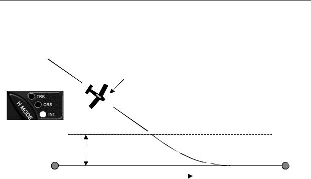
Intercept Mode (INT)
The intercept mode is used to intercept or regain the original flight plan track for some reason, such as when you have flown some distance from your intended flight plan and wish to return to it.
Autopilot flies INT mode to intercept GPS course
|
As the aircraft nears the GPS course line the |
|
|
autopilot automatically switches to TRK |
|
|
X |
|
|
Intercept Boundary |
|
|
Variable distance, depending on speed, to allow smooth intercept |
|
WPT |
GPS course line |
WPT |
In both the CRS and INT mode, the ground track heading may be changed by rotating the encoder knob or using the PCS steering mode of operation.
In the Course (CRS) mode, rotating the encoder clockwise causes a course change to the right. Counterclockwise rotation will cause a course change to the left. The course will change by 1 degree per “click” of the encoder, or, if rotated briskly, will change the course by several degrees during rotation
In the Intercept (INT) mode, the intercept angle to the original track may also be changed by rotating the encoder. The intercept angle will change in the direction that the encoder is rotated (as above). The Pro Pilot will automatically switch from the INT mode to the TRK mode as it crosses the intercept boundary.
|
|
|
Trio Pro Pilot Manual 3.8 |
10 |
|
Chapter 2
Vertical Navigation Overview (VNAV)
The V NAV function of the Pro Pilot controls the pitch axis of the aircraft. It provides commands to the pitch servo that attaches to the elevator control system. The V NAV system uses a rate gyro, pressure sensors, airspeed sensors and accelerometers as primary references in controlling the pitch attitude of the aircraft. The V NAV system does not depend upon a GPS signal for its functions.
Operation
While the Pro Pilot also has several vertical functions, the basic mode is that of “ALTITUDE HOLD.” A manual climb to altitude desired and a single press of the V NAV button will engage the pitch servo and maintain that altitude.
Three vertical navigation modes allow the pilot to maintain altitude, climb/descend at a selected vertical rate (in feet per minute) and preselect a target altitude. An additional pilot controlled steering capability allows the pilot to choose airspeed instead of vertical speed for the climb/descent by use of a button on the stick or yoke.
Basic V NAV Operation Modes
The capabilities of the V NAV system comprise three basic modes:
1.Altitude hold
2.Vertical climb and descent rates, and airspeed capture and control
3.Altitude pre-select, which can be used in conjunction with the vertical modes
Minimum and maximum safe airspeed management modes are also included to prevent stalling and over-speeding the aircraft.
Altitude Hold
To operate the altitude hold, fly to the desired altitude and level the aircraft in trim. Press the V NAV button to engage the pitch servo and the aircraft will hold at that altitude. Press the V MODE button and then rotate the encoder knob for minor adjustments to accommodate barometer updates.
Manually fly the plane to the desired altitude and engage the Altitude hold
|
|
|
|
|
|
|
|
Trio Pro Pilot Manual 3.8 |
11 |
||

Vertical Climb/Descent
The Pro Pilot also allows the pilot to select a desired climb or descent rate (i.e. VS (vertical speed), in ft. per minute). Press the V MODE button again and:
Set the desired climb or descent rate by rotating the encoder knob. Press the encoder knob to initiate
Once the desired altitude has been achieved, press the encoder knob again to hold that altitude.
Airspeed Capture and Control (using PCS)
During climb and descent the desired airspeed can be adjusted using the PCS (Pilot Command Steering) mode (see page 31). After the airspeed has been captured the airspeed can be increased by rotating the encoder clockwise, or decreased by rotating the encoder counterclockwise. This feature can be useful to ensure adequate cooling of the engine during climb.
Set the desired climb or descent airspeed by employing the PCS (Pilot command Steering) mode. Press/Hold the remote disconnect button and establish the climb/descent airspeed.
Once the desired cimb/descent airspeed has been achieved, release the button. Aircraft will continue to climb/decend at that airspeed.
Altitude Pre-Select
The Pro Pilot adds the ability to climb or descend to a pre-selected a target altitude. Press V MODE to advance to Altitude Select (ALT SEL). Rotate the encoder knob to select target altitude.
Set a desired climb or descent rate and enter a target altitude. Press the encoder knob to initiate.
The aircraft will climb or descend at the desired vertical rate and will automatically level off at the target altitude.
|
|
|
Trio Pro Pilot Manual 3.8 |
12 |
|

Chapter 3
Control and Display Overview
The control and display unit is designed to fit in a standard 3 1/8 inch instrument cutout in the instrument panel and requires approximately a 7 inch clearance behind the instrument panel. The unit is powered from the airframe +12V DC system. +28V DC systems are also available. All controls are located on the front panel.
Switch Function and Operation
ON/OFF Switch
The ON/OFF switch applies aircraft power to the Pro Pilot. In the OFF position, the Pro Pilot is disconnected from the aircraft control system. It is recommended that the Pro Pilot be turned on immediately after engine start. Upon power up, the display presents a logo and the current Pro Pilot firmware code version (or a customized screen) and sets several default conditions as follows:
Upon power up, the screen will display the un-calibrated field elevation (if the aircraft is on the ground) or un-calibrated altitude (if the aircraft is flying). The value is expressed in feet.
The pilot must adjust this value to agree with the primary aircraft altimeter, which has been previously adjusted to the reported barometer setting.
Once the Pro Pilot altimeter has been adjusted, pressing the encoder knob will enable the navigation screen.
Operation
Initially, with GPS data available, the TRK (Track) mode is selected and the TRK LED is illuminated. This mode is not fully operational until valid GPS data is available. When GPS is unavailable for seven seconds, or after initial power up, the display will default to a flashing "NO GPS" message.
NOTE: No H MODE LEDs will illuminate until valid GPS data is available.
Without GPS input, the autopilot will still function as a wing leveler and the rotary encoder can be used to initiate turns to the left or right or to correct airplane heading drift for straight ahead flight. Because the V NAV function does not rely upon GPS, the altitude hold system will be unaffected.
Once GPS data is present and validated, full navigation functionality is available and the TRK LED will illuminate.
If no flight plan or “GOTO” waypoint has been selected in the GPS receiver, a “NO FLTPLN” message will appear and the course mode (CRS) is automatically selected (CRS LED illuminated).
All servo power is initially off on power up and the Pro Pilot is disconnected from the aircraft control system.
|
|
|
Trio Pro Pilot Manual 3.8 |
13 |
|
H MODE and V MODE buttons
The H MODE switch controls the selection of the TRK (track), CRS (course) and INT (intercept) modes. With GPS data present, the default mode during power up is TRK.
Pressing the H MODE switch repeatedly advances the display screen from:
TRK ---> CRS ---> INT and then back to TRK.
The appropriate LED illuminates in each mode.
No H MODE LEDs will illuminate until valid GPS data is available.
At any time while in the INT mode, the pilot may transition to the TRK mode, or through TRK to CRS mode, by pressing the H MODE switch.
The H NAV button also provides the “AUTOMATIC COURSE REVERSAL” feature which does an automatic roll servo engagement and ground track reversal. Please see page 27 for operation instructions for this feature.
The V MODE switch controls the selection of the ALT HLD (altitude hold), AS/VS (airspeed/vertical speed), and ALT SEL (target altitude set) modes.
Pressing the V MODE switch repeatedly advances the display screen from:
ALT HLD ---> AS/VS ---> ALT SEL BARO SET.
The appropriate LED illuminates to signify data has been changed or entered on that screen. The ALT HLD LED is illuminated when the altitude hold mode is active, or the VS mode is active and the vertical rate is set to zero. The ALT HOLD mode LED will flash to indicate that an executed fine altitude adjustment is in progress.
|
|
|
Trio Pro Pilot Manual 3.8 |
14 |
|

Roll (H NAV) & Pitch (V NAV) Servo Activation
The H NAV and V NAV pushbuttons activate the roll and pitch servos, respectively. When the H or V LED is unlighted, the respective servo is inactive and that autopilot function is disconnected from the control system. When the LEDs are illuminated, the Pro Pilot is engaged and providing control signals to the Pitch and Roll servos.
The roll servo is activated (or deactivated) by pressing the H NAV pushbutton momentarily.
The pitch servo is activated (or deactivated) by pressing the V NAV pushbutton momentarily.
The servos may be operated independently of each other.
Remote Disconnect Switch
A remote servo disconnect switch (not supplied) is strongly recommended and should also be mounted on the aircraft control stick. Pressing the remote disconnect button momentarily will immediately disconnect both the pitch and roll servo, freeing the aircraft controls for manual operation. This same remote disconnect switch also provides an important additional functionality called Pilot Command Steering (PCS) which is used for both for horizontal and vertical navigation.
Note: While it is not recommended, the user may wire a separate remote disconnect switch for independent control of each servo. See the wiring diagram in the back of this manual.
Rotary Encoder - Pushbutton Switch
The black knob in the center of the control head implements three important functional control mechanisms.
1.It can be rotated for inputting or changing selections or inputs
2.Pressing the knob activates a momentary switch
3.In a single operation it may be pushed in and rotated at the same time.
Each of these provides varying functions, depending upon which mode of operation has been selected with either the H MODE or V MODE pushbuttons. Pressing the V MODE button will allow the encoder to change parameters associated with the altitude control, while pressing the H MODE button will allow encoder adjustment of functions associated with horizontal navigation.
The encoder switch is used in conjunction with the CONFIGURATION or PREFERENCE modes to change various settings. These are described in the setup menus (Chapter 9) of the manual.
The Display Arrow
An arrow is centered in the top line of the display. The arrow indicates which functions (H MODE or V MODE) the rotary encoder (and its pushbutton) will control when it is operated.
When the arrow points to the left, the encoder will control the H MODE functions.
When the arrow points to the right, the encoder will control the V MODE functions.
|
|
|
Trio Pro Pilot Manual 3.8 |
15 |
|

The H MODE or V MODE button, when pressed, will change the arrow direction and transfer encoder control to the appropriate mode.
NOTE: When switching the display/encoder from H MODE to V MODE the initial button press will simply change the direction of the arrow and some display parameters.
The encoder pushbutton switch performs a number of functions, depending which way the arrow is pointing. It is important to note the direction of the arrow BEFORE initiating any encoder action to assure that the proper values are changed.
H MODE Encoder Functions
If the arrow is not pointing to the left, press the H MODE button
1 – Display Data Fields
The pushbutton of the encoder switch selects what data is presented on the upper right field of the display. Rotating the encoder pushbutton advances the lower right line variable display field through the available field selections. The selections are described beginning on page 20.
Pressing and holding the encoder button down, then rotating it, selects and adjusts the track offset parameter which will be displayed in the upper right variable display field (see function 3, below).
2 – Scan Mode
Pressing the encoder pushbutton switch rapidly two times in quick succession (double-click) will cause the variable field data in the right part of the lower line to “scan” (or scroll), providing a sequential display of the various GPS data elements being received.
The turn coordinator information is not provided in the “scan” mode; however, it is available in the upper right field (see Function 5 below).
Exit from the scan mode is accomplished by double-clicking the display button again. Whenever the SCAN mode is active a small dot will appear in the display in front of the lower right data field indicating the SCAN mode is active.
3 – Top Line Data Selection
To select the data that will be displayed in the right side of the top display line, the user may momentarily press the encoder knob. A press and release cycle will advance the upper right display field to the next display parameter. (Do not rotate the encoder – press only!)
NOTE: The TOP field (track offset position) is selected and adjusted by pressing, then holding and rotating the encoder knob (in the H MODE only).
4 – Track Offset Position (TOP) Control
In the TRK mode, the rotary encoder is used to set a Track Offset Position (TOP). The TOP field is selected and adjusted by pressing, then holding and rotating the encoder knob (This is only possible while in the H MODE display with the arrow pointing to the left). The display will change in one/tenth mile increments to the left or right to a maximum of three miles from the centerline.
5 – Ground track Adjustment
In either the course (CRS) or the intercept (INT) modes the rotary encoder is used to select the ground track that the autopilot is commanded to follow. Rotating the encoder changes the commanded course in one-degree increments per “click” of the encoder. Rotating the encoder quickly changes the course in larger increments. Rotating the encoder counterclockwise alters the
|
|
|
Trio Pro Pilot Manual 3.8 |
16 |
|

commanded course to the left, while rotating the encoder clockwise alters commanded course to the right. (This is somewhat comparable to a traditional “Heading Bug” function).
6 – Drift Correction (NO GPS mode only)
Rotating the encoder to the right or left allows the pilot to adjust roll TRIM either right or left by one trim count. This is a very fine trim adjustment. The upper right field in the display will provide a graphic display of the trim position while the switch is activated and for about two seconds after the encoder action is stopped.
If the GPS data to the Pro Pilot is unavailable, as indicated by a NO GPS warning, the encoder knob switch provides a method to turn the airplane to a new heading or stabilize the aircraft in a straight and level attitude. The pilot may monitor the rate of turn by observing the aircraft directional gyro or compass.
7 – Entering “PREFERENCES MENU”
Pressing and holding the encoder pushbutton for more than 3 seconds causes entry into the PREFERENCES MENU for adjusting the parameters and features for both the horizontal and vertical portions of the Pro Pilot. This feature is explained in Chapter 9.
V MODE Encoder Functions
If the arrow is not pointing to the right, press the V MODE button
1 – Activate Climb or Descent
Press the V MODE button repeatedly to display the VS SET screen. Enter a climb or descent rate by rotating the encoder. Pressing the encoder will initiate the function.
NOTE: The servo must be engaged by pressing the V NAV button for climb or descent. If engaged, the flashing LED(s) will confirm the execution of the commands.
2 – Activate Climb or Descent to a Pre-Selected Altitude
Press the V MODE button repeatedly to display the ALT SEL screen. Enter a destination altitude by rotating the encoder. Rotating the encoder will increase or decrease the selected altitude in hundreds of feet. Pressing and rotating the encoder will change the display in thousands of feet. Pressing the encoder momentarily thereafter will first present the BARO SET screen to allow correction of current altitude. A second press of the encoder (or waiting for 5 seconds to timeout) will initiate the function.
An altitude correction can be made and the encoder pressed to activate the vertical profile. If the encoder button is not pressed, the autopilot will automatically activate the vertical profile several seconds after the last rotation of the encoder.
NOTE: The climb/descent rate will be at the vertical speed selected on the VS SET screen or, if none was entered, the system will use the default vertical rate that was previously entered in the
CONFIGURATION menu.
3 – Altitude Control Functions
When the Altitude Hold is engaged, the encoder knob is used to make fine adjustments to the altitude. It is also employed to set a desired climb/descent rate when on the VS SET screen, and it is used to select a target altitude when it is on the ALT SEL screen.
4 – Setting the Barometric Altitude
The encoder is used to adjust the barometric altimeter (BARO SET) when required.
|
|
|
Trio Pro Pilot Manual 3.8 |
17 |
|
Chapter 4
Preflight Power Up
This section discusses what must be accomplished when “powering up” of the Pro Pilot, items to be checked and adjusted, and a flight example
On power up the Pro Pilot will briefly display the logo screen. This will be followed by a screen requesting verification of the current field elevation or altitude.
Note: The TRK LED is illuminated after the GPS signal is acquired and the H NAV servo is not activated (“H” LED is not illuminated). The aircraft roll control (ailerons) should be free and clear indicating the servo is disconnected from the control system.
A preflight check on the Pro Pilot at this point would be to engage the servo by pressing the H NAV pushbutton momentarily and noting that the “H” LED illuminates. The servo is now locked to the control system. Using the control stick or yoke, the pilot should intentionally force the ailerons to their extreme positions to verify that the slip clutch on the servo will allow the pilot to continue to fly the airplane in the event the servo malfunctions.
If this check is satisfactory the H NAV button should be pressed again to disconnect the autopilot from the controls. Verify that the LED is not illuminated and the servo is not engaged for takeoff.
Important: If all of the above actions cannot be properly achieved, turn the Pro Pilot off and do not attempt to engage the autopilot in flight. If there is any indication of an aileron control system problem do not fly the airplane until it has been corrected.
Since the GPS is not yet powered up, after about 7 seconds the display will show the NO GPS message.
The pilot now applies power to the GPS unit that is connected to the Pro Pilot and programs the GPS flight plan. On GPS power up, the display on the Pro Pilot may show navigation data momentarily on the display, as some GPS receivers will send sporadic GPS data. Typically, the NO GPS message will return as this data transfer ceases.
When the GPS receiver attains satellite acquisition and lock, the Pro Pilot will display the power up default screen previously illustrated.
Some GPS receivers, even though they have obtained satellite lock, do not put out valid NMEA or AVLINK data until a flight plan or “GO TO” waypoint is entered or a preset groundspeed is attained (usually 2 to 5 knots). In this case either the “NO GPS” message or the “NO FPLAN” message will be displayed.
Some GPS receivers’ output data are capable of providing ground track and groundspeed information to the Pro Pilot after satellite lock, even before a flight plan is entered. The Pro Pilot will detect this and provide the pilot with a modified CRS mode capability.
In this mode, manual transition to the TRK or INT mode is inhibited and NO FPLAN is displayed on the screen. In the NO FPLAN mode the pilot may use the autopilot CRS mode to fly a selected ground track. Once a flight plan has been entered the TRK mode is automatically selected.
The flight plan is now entered and activated in the host GPS unit. As the first “TO” waypoint becomes active the Pro Pilot will display the parameters associated with navigation to that waypoint. A check should be made to verify agreement between the data displayed on the Pro Pilot and the host GPS system.
|
|
|
Trio Pro Pilot Manual 3.8 |
18 |
|

Chapter 5
Information Fields
Horizontal Navigation (H NAV)
Pilot information for navigation is provided on a high contrast, bright Polymer LED (OLED), or an optional transflective LCD screen. Several fields on this display are multiplexed (i.e. they use the same display space to present different information). This allows the pilot to view all navigation parameters including digital rate of turn information. This section will explain in detail the horizontal navigational features and display screens available.
Power up Display
When the Pro Pilot is powered on a logo display is present showing the firmware revision operating in the unit. (This can be field programmed to present a personalized screen at power on).
Initial Logo Screen
The initial factory logo screen shows the product information including the firmware revision level and unit serial number in the extreme right part of the display (represented by the X’s).
The purchaser may program a personalized logo screen. Each time the unit is turned on it will display this information. This information can be field re-programmed at any time by entering the CONFIGURATION menu screens (Chapter 7).
BARO SET Screen
When the Logo screen expires after a few seconds, the BARO SET screen will be seen.
No functions will be available until the altitude value is set and the encoder is pressed. The value should be set to agree with the primary aircraft altimeter, which has been corrected for current reported barometric pressure. The value may be changed in either five foot (ELEVATION) while on the ground or twenty foot (ALTITUDE) increments while in flight.
If GPS signals are present on the Pro Pilot interface the display will switch automatically to the navigation display. If no GPS signals are present the screen will change to show that NO GPS is being received on the interface.
NO GPS Screen
The “NO GPS” screen will display on power up if no GPS signal is present or if the GPS signal is lost for a period exceeding seven seconds.
In all cases the navigation display will return to normal automatically when the GPS signals are reacquired.
Note: There may be a delay of up to seven seconds in restoring the display after a GPS signal becomes active on the interface.
In the event the GPS signal is lost during normal area navigation, the "NO GPS" screen will be shown and the Pro Pilot will automatically go into the wing leveler mode and follow a “straight and level” course. In this mode, manual corrections to the dead reckoning track can be made using encoder knob.
|
|
|
Trio Pro Pilot Manual 3.8 |
19 |
|

No H MODE LEDs will be illuminated until valid GPS data is available.
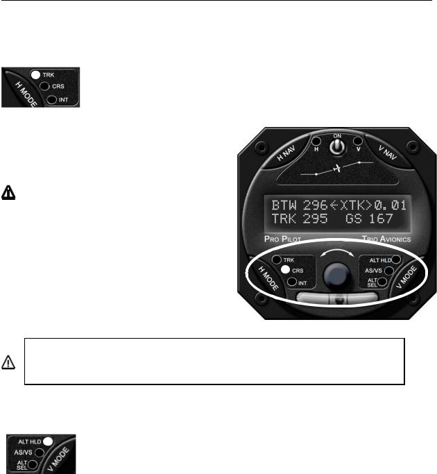
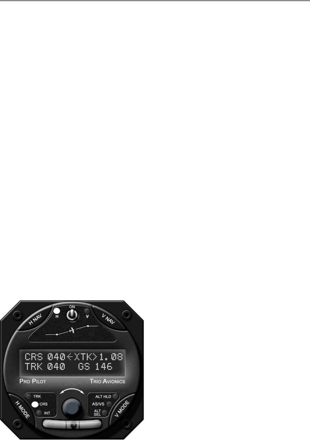
Normal Power Up Display, GPS Active
On power up, once the BARO SET has been performed, the Pro Pilot defaults to the H MODE display and the TRK mode of operation when valid GPS data is available.
The image shows the Pro Pilot display with a good GPS signal present, and flight plan entered. Note that the “H” (H NAV) LED is illuminated.
This indicates that the roll servo has been activated by pressing the H NAV button and the Pro Pilot is providing horizontal navigation, having taken control of the roll axis of the aircraft.
To view and control horizontal functions at any time it is necessary to press the H MODE button one time to transfer encoder control to the H NAV functions. The mid upper arrow will point to the left. No navigational changes will occur.
Track Display Information
Bearing To Waypoint Field (BTW)
The bearing to waypoint (BTW) field is located on the left side of the top line as illustrated. This field is updated whenever the GPS data to the Pro Pilot is refreshed, normally once every one or two seconds, depending on the GPS interface data rate. (A GPS with NMEA data output generally updates once every two seconds, while an Aviation Data Link updates once every second). BTW is the exact magnetic bearing from the current aircraft position to the next GPS route waypoint.
Note: The line directly below the BTW data contains the current track (TRK) information (if these two numbers are identical, the aircraft is tracking directly to the destination waypoint regardless of the actual magnetic heading of the aircraft).
Ground track Field (TRK)
The ground track (TRK) field is located on the line directly below the “Bearing to Waypoint” (BTW). The TRK field is the current track over the earth based on the GPS updates every one or two seconds.
Variable Field, Top Line
The right side of the upper line of the display may be changed to present any data derived from the GPS available in the bottom line right field or an electronic rate of turn display. The factory default display is to present the information shown, but the user may wish to otherwise configure this segment. The top line variable field may be changed by repeatedly pressing the encoder knob while in the Track (TRK) mode. Rotating the encoder will change the variable field in the bottom line. “Double clicking” the encoder knob will cause the bottom line variable field to continually sequence through all available information. “Double clicking” again will exit the scan mode.
|
|
|
Trio Pro Pilot Manual 3.8 |
20 |
|
Cross Track Error Field (XTK)
Cross Track Error Field (XTK) provides a distance measurement in miles, tenths and hundredths of how far the aircraft is positioned either right or left of the desired track (DTK). The maximum value in this field is 9.99 miles.
A positioning symbol, immediately preceding the numerical data, indicates the "fly to" direction required to null this error.
If this symbol has its apex to the left (<), the autopilot will fly to the left to eliminate the error.
If the symbol has its apex the right (>) the autopilot will fly to the right to eliminate the error.
Here the aircraft is just .02 miles to the right of the desired track, so the autopilot will fly to the left to resume correct DTK.
Other Available Fields on the Bottom Line
The bottom display line, extreme right field is another variable field used to display other tracking data of interest to the pilot. The possible data fields displayed are:
GS Groundspeed, closure speed to the destination waypoint
ETE Estimated time en-route, in hours and minutes format
ETe Estimated time en-route, in minutes and seconds format
RNG Distance from the current “TO” waypoint
(WPT) "TO" waypoint identifier *
(TC) Digital graphic turn coordinator display *
DIS? Distance tolerance error indicator
TRN? Turn tolerance error indicator
SPD? Speed tolerance error indicator
TOP Track Offset Position indicator
VS Vertical Speed mode indicator**
AH Altitude Hold mode indicator**
*No associated label field displayed
**Shown if the VNAV servo is on
Each field above except the DIS?, TRN? and SPD? fields is selected by pressing the encoder pushbutton momentarily. The DIS?, TRN? and SPD? fields are automatically displayed to indicate GPS data anomalies.
The ETE or Ete label format is selected automatically by the autopilot. The TOP field will not be displayed if the TOP value is 0.00 (no offset).
Groundspeed (GS)
The GS (groundspeed) field indicates the aircraft speed over the ground in knots as provided by the host GPS system. This field has a maximum value of 999 knots per hour.
|
|
|
Trio Pro Pilot Manual 3.8 |
21 |
|
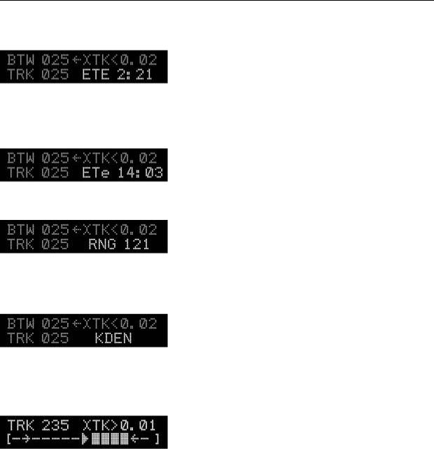
Estimated Time En-route, HH:MM (ETE)
The ETE (estimated time en-route) field shows the time to the current waypoint based on the closing velocity (NMEA link only) to the waypoint (which may be different from the groundspeed GS/distance calculation discussed above).
If the last "E" in the ETE label is in upper case the display format is HH:MM, hours and minutes. This is switched automatically between HH:MM and MM:SS (minutes and seconds) as ETe depending on the results of RNG/GS (distance/closing velocity) calculation.
Estimated Time En-route, MM:SS (ETe)
This field is identical to the ETE field except the format is MM:SS (minutes:seconds). This format is automatically displayed when the RNG/CLOSING VELOCITY calculation indicates the next waypoint is less than 60 minutes away.
Range to A Waypoint (RNG)
This field contains the distance remaining to the current “TO” waypoint with the least significant digit being in tenths of a mile. If the distance is over 100 miles the least significant digit is in units of nautical miles (GPS NMEA serial data output is
always in nautical miles, even though the GPS screen may be set to statute miles). This field is limited to a maximum value of 999 miles.
Waypoint
The waypoint identifier currently programmed as the “TO” waypoint is presented in this field. Up to six alphanumeric characters are available for this data field, allowing for
intersection and user waypoint identifications. This field will flash at a 2 pulses per second (PPS) rate for approximately 10 seconds when past the last waypoint in the route or past the last GOTO waypoint or if the aircraft is being flown more than 90 degrees away from the waypoint.
Digital Rate of Turn Display
A digital graphic representing the current yaw rate is presented to the pilot when this field is selected. The limit on this rate is approximately ±4.5 degrees per second full scale.
On the turn rate display the 3 deg/sec rate is denoted by the tip of the arrow presented in the display line. The display shows a standard rate turn to the right.
Automatic Field Scan Mode
If the encoder knob is momentarily pressed two times in quick succession (double-clicked) the variable field will enter or exit the “Scan Mode.” In this mode the data displayed is sequenced in the display at a 2.5 second rate. Additionally, it will also show the status of the altitude control functions when they are engaged.
This can be useful for sequentially monitoring all of the parameters put out by the GPS without having to select each parameter manually.
|
|
|
Trio Pro Pilot Manual 3.8 |
22 |
|
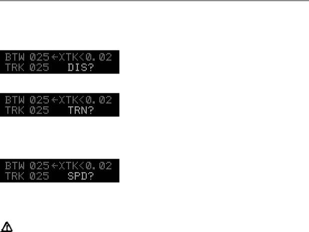
GPS Data Anomalies
DIS?
DIS? is displayed in this field whenever the maximum distance in the GPS data stream is greater than 999 miles. Tracking functions are not affected by this condition.
TRN?
The TRN? warning is displayed in this field when the Pro Pilot detects a negative closing velocity (going away from the “TO” waypoint).
This usually occurs when a waypoint greater than ± 90 degrees from the current waypoint is selected. No pilot action is required.
SPD?
The SPD? warning field is presented to the pilot when the parameters in the GPS data stream indicate a condition that results in an overflow of the ETE computation.
Under normal operation, these conditions should not exist; however, momentary corruption of the GPS data during signal acquisition or waypoint transitioning can cause these to appear. No pilot action is required.
Tracking functions are disabled until the condition is cleared automatically, usually on the next GPS update. Wing leveling remains in operation.
|
|
|
Trio Pro Pilot Manual 3.8 |
23 |
|
Chapter 6
Horizontal Operation
Track Mode (TRK)
The track mode (TRK) is used to track a GPS flight plan or fly directly to a “GOTO” waypoint. The autopilot uses the data stream from the GPS for determine the direction of flight.
If a flight plan has been entered into the GPS, the autopilot will fly the courseline to each point in the flight plan in sequence.
If a “GOTO” waypoint has been selected, the autopilot will fly directly to the waypoint.
To use the TRK mode, press the H MODE button to light the TRK LED. Press the H NAV button. The autopilot will engage and fly the plane directly to the waypoint or the flight plan courseline. If the plane is some distance from the courseline, the pilot may use the intercept mode (INT) to quickly get back to the flight plan courseline.
This mode requires a valid GPS signal to provide position information. If no GPS signal is present, this function will not be available.
Tracking a Course (CRS)
The course mode (CRS) may be compared to flying a heading bug in a traditional system, keeping in mind that you are selecting a course-over-the-ground and not a magnetic heading. Initially when entering this mode the course and track will be identical. If the pilot wishes to change the track of the plane, rotating the encoder knob will change the heading (like changing a heading bug). The autopilot will then change course until the CRS and TRK are once again identical.
Example: If given a heading to fly by ATC, press the H MODE button to light the CRS LED, rotate the encoder until the desired course is shown and press the H NAV button. The autopilot will engage and smoothly turn the airplane to the desired course.
Using Course Mode
Assuming the track mode (TRK) is currently selected, press the H MODE pushbutton to change the H MODE LED and display to the course mode (CRS).
When switching to the CRS mode the BTW label on the left side of the top line changes to CRS.
The three numeric characters following CRS represent the pilot commanded ground track. The CRS will show the current ground track (heading) the plane was traveling when the mode is entered.
The Pro Pilot will turn the plane to keep the track (TRK) and the course (CRS) the same value.
|
|
|
Trio Pro Pilot Manual 3.8 |
24 |
|
Example: If the current ground track is 010 degrees when the CRS mode is selected, the commanded course (CRS) will be initialized to 010 degrees.
If H NAV servo is activated while in the CRS mode, the current track over the ground is automatically entered as the commanded CRS.
If the servo is OFF just select the CRS mode. Then, push the HNAV button (turning on the servo). This will cause the current course to be selected and flown.
The TRK field below the CRS field indicates the actual across-the-ground track (TRK) from the GPS.
While in the CRS mode, rotating the encoder knob allows the pilot to adjust the commanded course in one degree increments either right or left of its current value. Rotating the encoder more quickly changes the course in larger increments. After changing the CRS field with the encoder the plane will turn left or right until the CRS and TRK fields are once more the same.
The distance right or left of the desired track is indicated in the XTK field in the top right line and is preceded by a left or right pointing apex (< or >), which shows which direction the airplane needs to fly to get back on the original flight plan or “GOTO” waypoint.
The pilot may exit the CRS mode by pressing the H MODE button until the desired mode (INT or TRK) is selected.
Note: If the XTK error is inside the intercept boundary line, the autopilot will sequence directly from CRS to TRK (bypassing the INT mode) when the mode button is momentarily pressed.
The PCS (Pilot Command Steering) mode provides an alternate mode of entry to the CRS mode and is described on page 31.
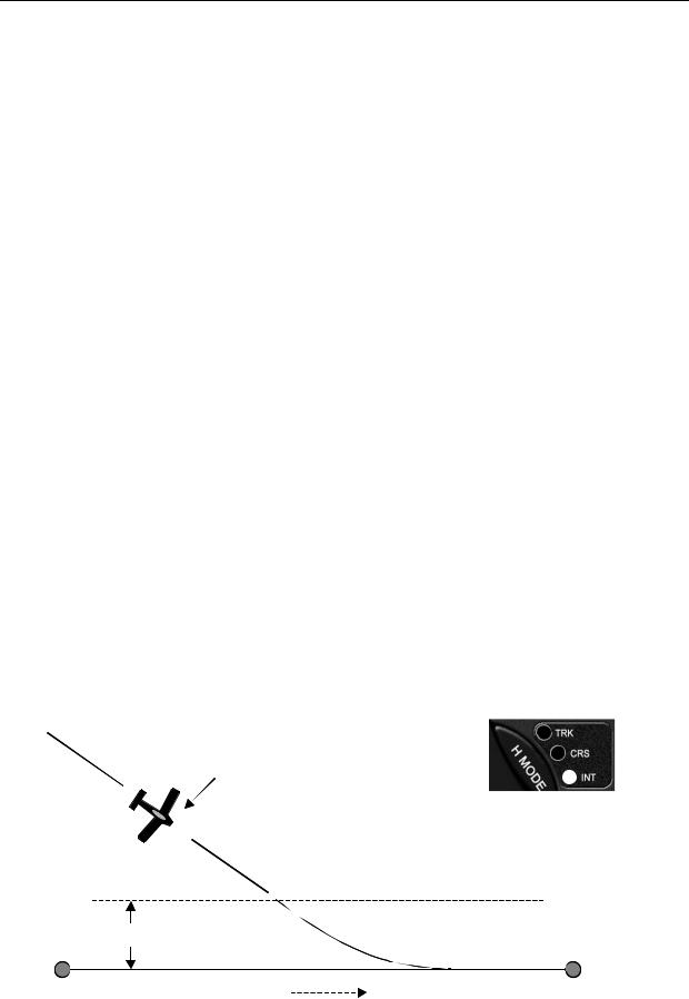
Intercept a Course (INT)
The intercept mode (INT) is designed to bring the aircraft back onto the original desired track after being vectored around by ATC or when avoiding weather or flying around airspace restrictions. INT is useful to bring the plane back to the original flight plan course (or Airway) instead of using the GOTO feature to take you to the next waypoint (e.g. “resume normal navigation”). While in the INT mode the pilot is also able to adjust the course intercept angle as desired.
Intercept Operation
INT is activated by pressing the H MODE switch (to sequence from the TRK or the CRS mode) until the INT LED is illuminated.
Autopilot flies INT mode to intercept GPS course
|
|
Autopilot in INT |
|
|
As the aircraft nears the GPS course line the |
||
|
autopilot automatically switches to TRK |
|
|
|
X |
|
|
|
Intercept Boundary |
|
|
|
Variable distance depending on speed to allow smooth intercept |
|
|
WPT |
GPS course line |
WPT |
|
|
|
|
|
Trio Pro Pilot Manual 3.8 |
25 |
||
 Loading...