

Page 1
ASSEMBLY INSTRUCTIONS
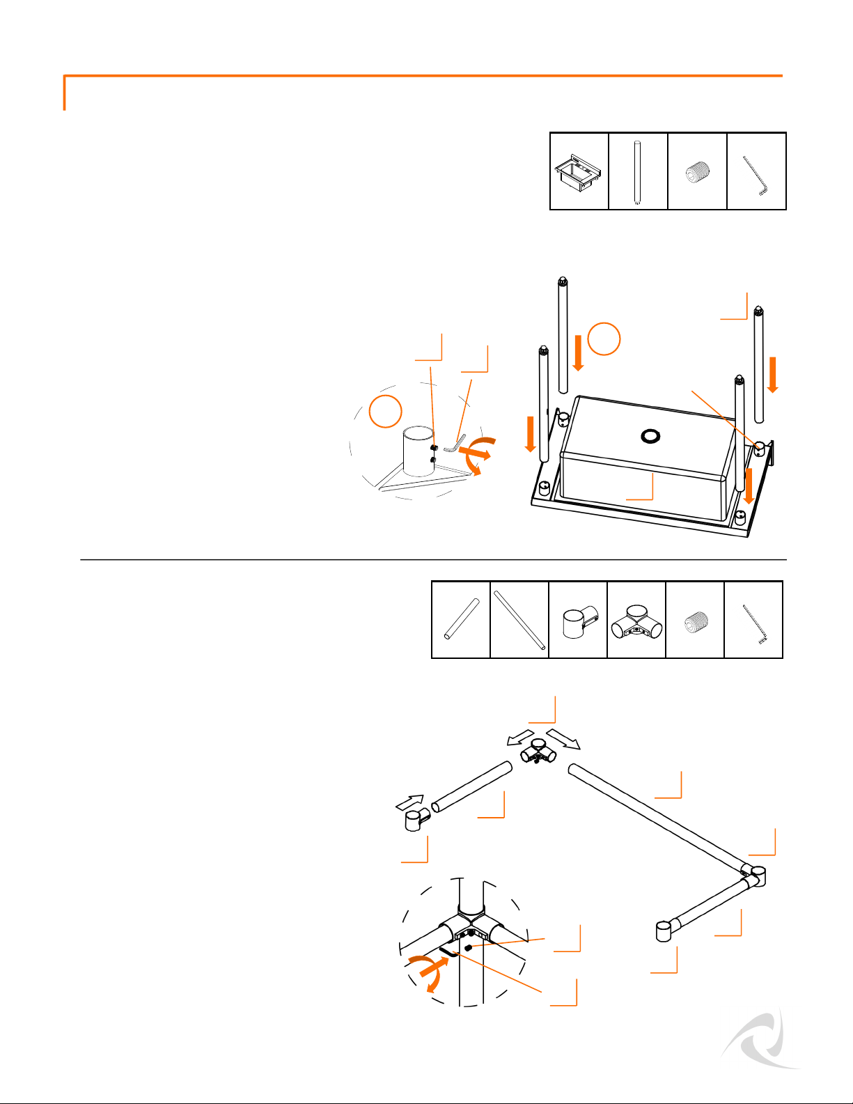
Unscrew HEX SCREWS (I) that are preinstalled on Connectors (G/H) until Cross
Beams (E/F) can be fully inserted.
On a flat surface connect Connectors (G/H)
and Cross Beams (E/F) into a U-shape as
shown in diagram.
Make sure all Cross Beams (E/F) are pushed
all the way into the Connectors (G/H).
Use HEX KEY (K) to tighten HEX SCREW (I)
against Cross Beams
With two people, lay SINK (A) upside-down.
Unscrew HEX SCREWS (I) that are preinstalled on Leg Collars on bottom of SINK
(A) until LEGS (B) can be fully inserted.
Insert LEGS (B) into Leg Collars. Do not
tighten HEX SCREWS (I) until Step 3.
STEP 1
STEP 2
I (8)
K (1)
B (4)
B
A
A (1)
E
I
K
Leg Collar
1
2
G (2)
K (1)
F (1)
E (2)
H (2)
I (6)
E
H
F
I
K
G
H
© 2019 TRINITY - 800.985.5506
2
G
Page 2
ASSEMBLY INSTRUCTIONS
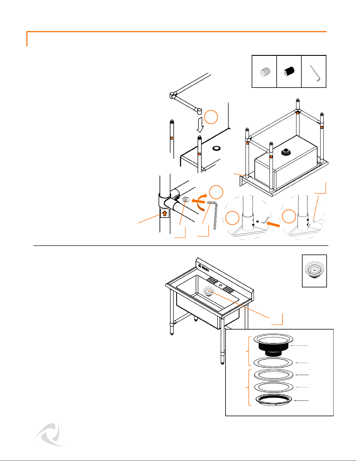
With two people, carefully turn sink rightside up, standing it upright.
Unscrew large 3-3/8” Nut from bottom of
DRAIN ASSEMBLY (D). From inside SINK (A),
insert Drain through White Seal and opening
at bottom.
From under SINK (A), first slide on Black
Gasket and Paper Gasket then screw large
3-3/8” Nut back on tightly. If necessary,
use a pipe wrench to tighten.
Note: P-trap NOT included.
With two people, take Cross Beams
assembly in STEP 2 and slide Connectors
(G+H) over all LEGS (B).
Use Alignment Stickers to help level out
Cross Beams, by lowering Cross Beam
assembly adjacent to stickers.
Tighten HEX SCREW (I) on each Connector
to LEGS (B) with HEX KEY (K).
Tighten both HEX SCREWS (I) on each Leg
Collar with HEX KEY (K). Place a SCREW
CAP (J) over each HEX SCREW (I).
STEP 3
STEP 4
D
I
D (1)
© 2019 TRINITY - 800.985.5506
3
Drain Assembly (D)
Inside
the sink
Under
the sink
Drain
Black
Gasket
Paper
Washer
3-3/8”
Nut
White
Seal
Alignment
Sticker
K
J
3
4
I (4)
K (1)J (8)
Leg
Collar
1
2
Page 3
ASSEMBLY INSTRUCTIONS
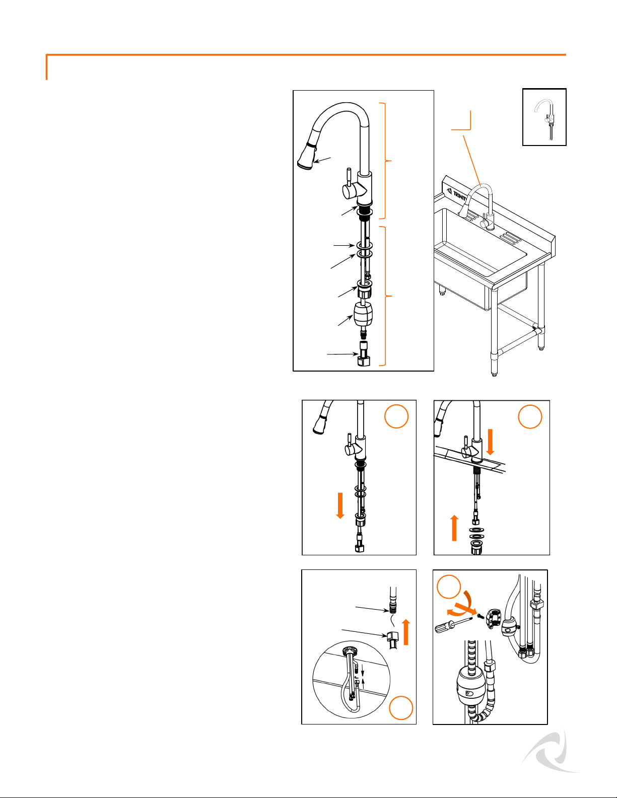
Unscrew Lock Nut from bottom of FAUCET
ASSEMBLY (C) and remove Lock Nut, White
Washer and Black Flat Gasket.
From top side, make sure Metal Base w/
Gasket is on top of SINK (A) and all 4 hoses
are straight and untangled. Insert FAUCET
ASSEMBLY (C) through hole, first with Quick
Connector hose, then hot and cold water
supply hoses with metal fittings, finally the
short hose with plastic cap.
Once all hoses are carefully threaded
through hole and FAUCET ASSEMBLY (C) is
sitting flush on top of SINK (A), align faucet
handle facing towards front of SINK (A).
From under SINK (A), first slide on Black Flat
Gasket, then White Washer, then screw on
Lock Nut. Tighten Lock Nut as much as you
can by hand. If necessary, use a pipe
wrench to tighten.
Remove and discard the Plastic Cap from
short hose and push Quick Connector to
connect two ends of hoses. You should
hear a soft click to indicate secure
connection and orange release button
should return to flush with housing. You may
also give two ends of hose a soft tug to
ensure they are connected securely.
Locate Counterweight in the box, use a
Phillips screwdriver to separate two halves
of Counterweight by unscrewing screws
securing them. Make sure Spray Head is
pushed up against the spout and pull-out
hose is dangling unhindered. Re-secure
Counterweight just above the turn of pull-out
hose, on side opposite Quick Connector.
Counterweight position can be moved up to
decrease amount of Spray Head pull-out if
desired.
STEP 5
C (1)
C
On top of
the sink
Under
the sink
© 2019 TRINITY - 800.985.5506
4
Faucet Assembly (C)
Spray
Head
Metal Base
w/ Gasket
Black Flat
Gasket
White
Washer
Lock Nut
Counterweight
Quick
Connector
Remove and discard
Plastic Cap
Orange release
button
Black Flat
Gasket
White
Washer
Lock Nut
Black Flat
Gasket
White
Washer
Lock Nut
1
4
2
3
Page 4
ASSEMBLY INSTRUCTIONS
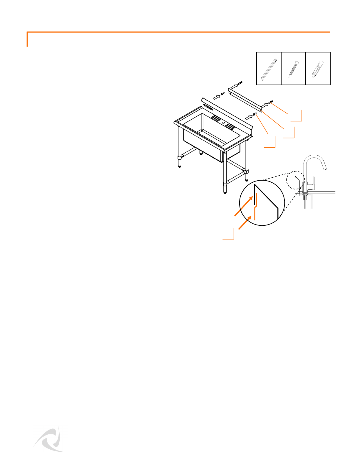
Carefully move sink against wall at your
desired location. If needed, use a pencil to
mark off mounting height of BRACKET (L).
Position BRACKET (L) on wall, marking off
fastening location on wall through holes on
BRACKET (L). Drill holes in marked locations.
Insert ANCHOR (N) completely into each
drilled hole. Fasten MOUNTING SCREWS (M),
through holes on BRACKET (L), into anchors
tightly with a screwdriver.
Slightly lift sink and hook flange of sink over
BRACKET (L). Adjust Feet Levelers to ensure
sink is stable and level. Connect Hoses and
Drain to plumbing system.
Note: Bracket is to prevent sink tipping,
NOT for mounting sink to a wall. Do NOT
mount sink to a wall without legs.
STEP 6
L (1) M (2) N (2)
L
M
N
flange
L
© 2019 TRINITY - 800.985.5506
5
 Loading...