

Page 1
OWNER’S MANUAL
TRINITY 24” Garage Wall Cabinet
Model # TLSPBK-0604
Page 2
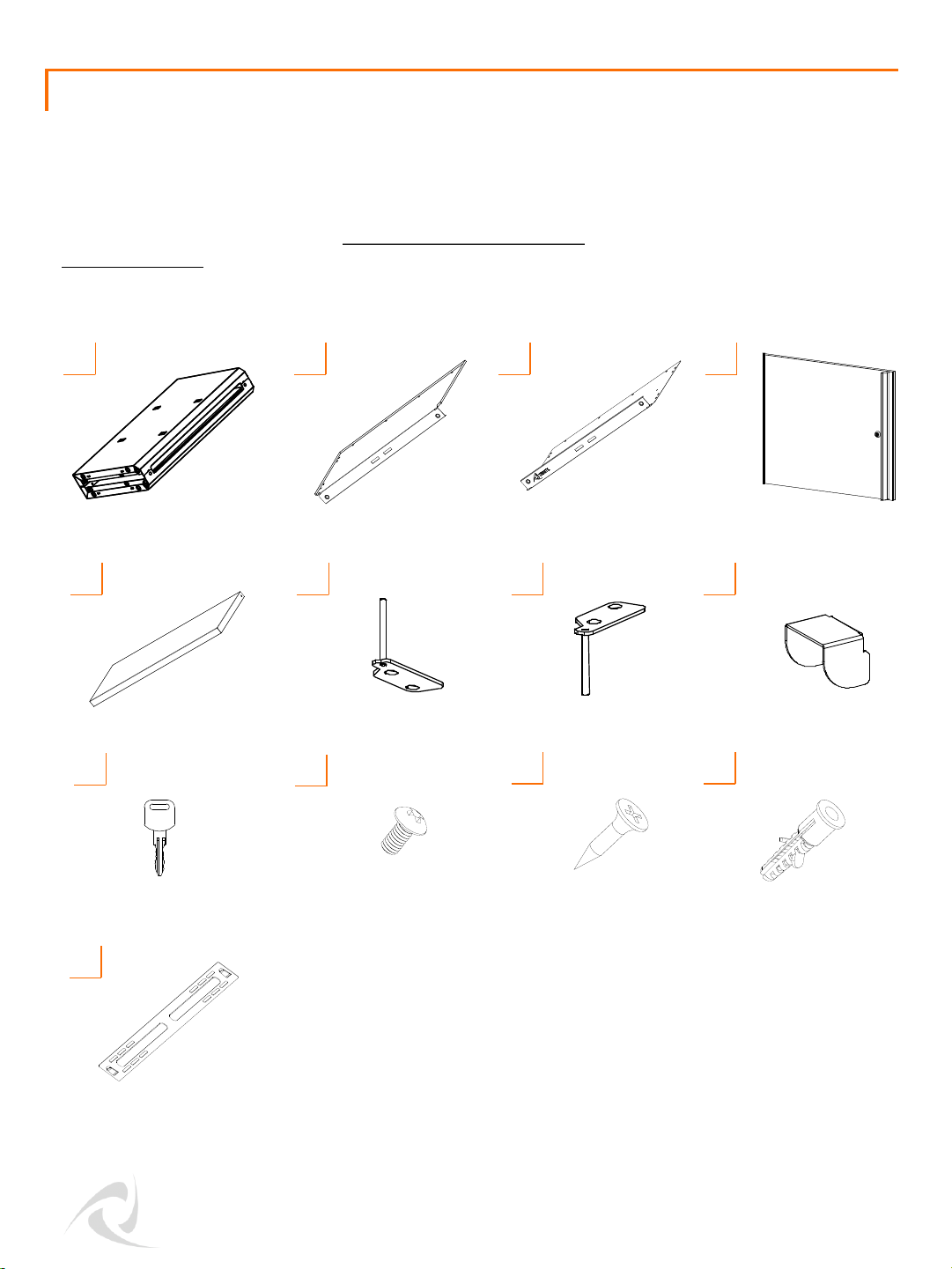
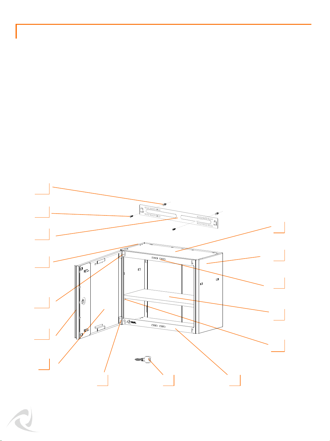
Your TRINITY 24” Garage Wall Cabinet should include the following parts. Please inspect box contents to
ensure you have received all components.
If you are missing any parts, need assistance with assembly or have questions, please contact TRINITY
Customer Service: 800.985.5506 or [email protected]. Parts can also be requested online at
www.trinityii.com (Help & More, Contact Us).
You will need a Phillips screwdriver for assembly which is not provided.
A B C D
J
DOOR HINGE-G (1)
G
© 2018 TRINITY - 800.985.5506
1
SHELF (1)
E
I
F
DOOR HINGE-F (1)
CABINET BODY (1) DOOR (1)BOTTOM PANEL (1)TOP PANEL (1)
H
SHELF SUPPORT (4)
KEY (2) BLACK SCREW
(24) + (2) extra
PARTS LIST
ANCHOR (4)MOUNTING SCREW (4)
WALL BRACKET (1)
K L
M
Page 3
2
© 2018 TRINITY - 800.985.5506
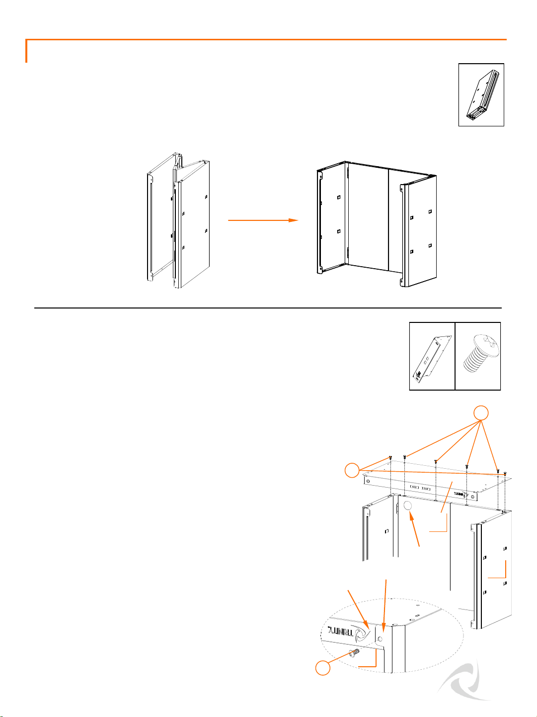
STEP 2
Unfold CABINET BODY (A).
A (1)
J (8)
Two people are recommended for ease of assembly.
Stand the unfolded CABINET BODY (A) upside down
on the floor.
Note: There is a 40mm diameter hole on the back
panel of the CABINET BODY (A). When the CABINET
BODY (A) is upside down, this hole should be in the
upper left corner of the back panel.
ASSEMBLY INSTRUCTIONS
STEP 1
C (1)
hole
Turn BOTTOM PANEL (C) upside down. Tilt the front diagonally
downward. First, insert the lip into the inner side of the tab of
CABINET BODY (A) at the right side, then insert into the left side.
Note: Do not install screws in the two holes at the right or left
front corners of BOTTOM PANEL (C) until instructed.
Follow the order indicated, insert (6) BLACK SCREWS (J) through
the hole on each back corner and four holes on the back side of
BOTTOM PANEL (C). Tighten them fully with a Phillips
screwdriver. Insert (2) BLACK SCREWS (J) through the tabs on
front of CABINET BODY (A) and tighten them fully to BOTTOM
PANEL (C).
1
2
A
C
lip
tab
J
3
Page 4
3
© 2018 TRINITY - 800.985.5506
J (4)
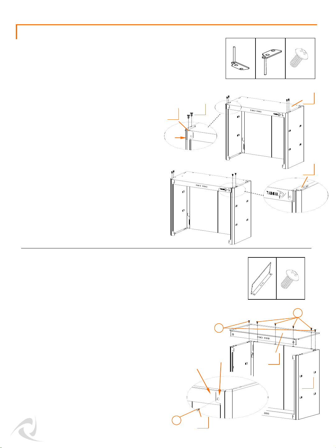
STEP 4
DOOR (D) can be installed on the left OR right
side of the cabinet. Only install one hinge in this
step.
RIGHT INSTALLATION:
Position DOOR HINGE-G (G) on the left front
corner of the outside of BOTTOM PANEL (C) and
align the holes. Make sure the pivot of hinge
faces down.
LEFT INSTALLATION:
Position DOOR HINGE-F (F) on the right front
corner of the outside of BOTTOM PANEL(C) and
align the holes. Make sure the pivot of hinge
faces down.
Insert (2) BLACK SCREWS (J) through the DOOR
HINGE (F or G) and (2) through BOTTOM PANEL
(C). Tighten fully with a Phillips screwdriver.
Stand the unit right side up.
Tilt front of TOP PANEL (B) diagonally downward. First, insert the
lip into the inner side of the tab of CABINET BODY (A) at the right
side, then insert into the left side.
Note: Do not install screws in the two holes at the right or left
front corners of TOP PANEL (B) until instructed.
ASSEMBLY INSTRUCTIONS
STEP 3
G (1)
B (1)
F (1)
J (8)
OR
Follow the order indicated, insert (6) BLACK SCREWS (J)
through the hole on each back corner and four holes on
the back side of TOP PANEL (B). Tighten them fully with a
Phillips screwdriver. Insert (2) SCREWS (J) through the tabs
on front of CABINET BODY (A) and tighten them fully to
TOP PANEL (B).
Open Left
Open Right
A
C
pivot
J
G
F
1
2
B
lip
tab
J
3
Page 5
4
© 2018 TRINITY - 800.985.5506
STEP 6
ASSEMBLY INSTRUCTIONS
STEP 5
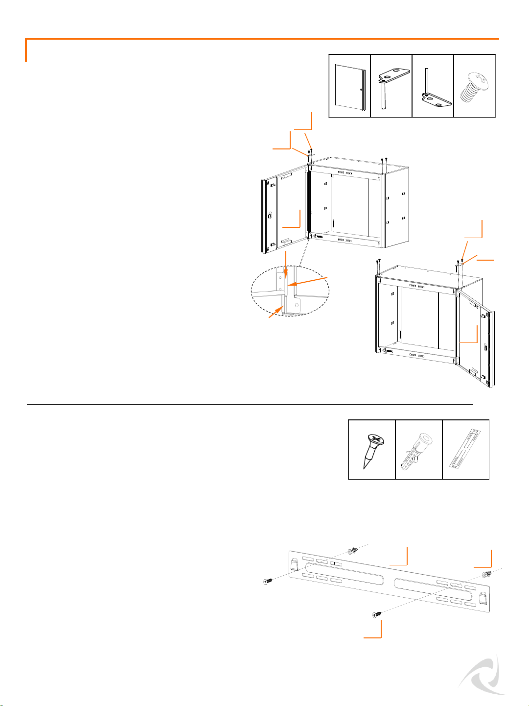
Attach DOOR (D) to the cabinet front by
sliding the bottom door cylinder over the
DOOR HINGE (F or G) installed in Step 3.
Position remaining DOOR HINGE (G or F) to
the left or right front corner of TOP PANEL (B).
Make sure to insert the pivot of DOOR HINGE
into the top door cylinder first.
Align holes on DOOR HINGE (G or F) to preinstalled nuts on frame of CABINET BODY (A).
Insert (2) BLACK SCREWS (J) through the
DOOR HINGE (G or F) and (2) through TOP
PANEL (B). Tighten fully with a Phillips
screwdriver.
G (1) F (1)
J (4)
OR
D (1)
M (1)
K (2)
L (2)
Position WALL BRACKET (M) on the wall at the desired
height.
If needed, use a pencil to mark off the mounting location
on the wall through one of the oval holes on each end of
WALL BRACKET (M). Drill holes in marked locations.
Insert ANCHOR (L) completely into each drilled hole.
Fasten SCREWS (K) through the oval holes on WALL
BRACKET (M) into the wall or anchors tightly with a
Phillips screwdriver.
Note: Please consult a local contractor if you are unsure
if your wall is able to bear the load of the wall cabinet.
Open Left
Open Right
G
pivot
cylinder
J
D
F
J
D
L
K
M
Page 6
5
© 2018 TRINITY - 800.985.5506
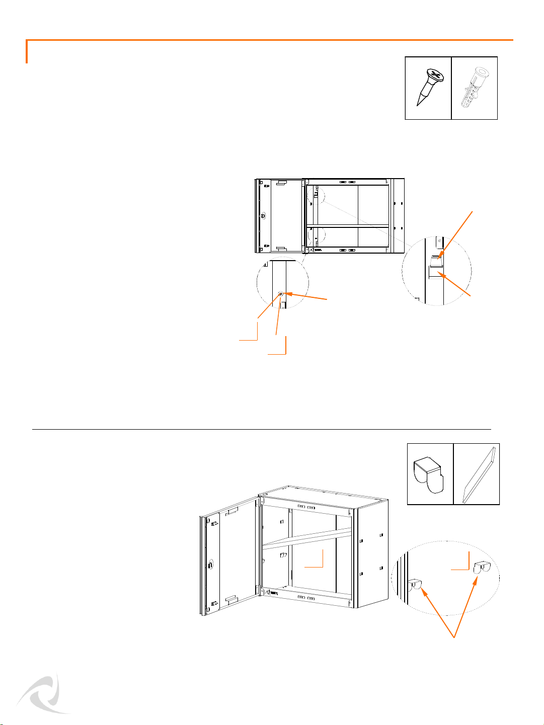
Lift the cabinet and hang it carefully on
two hooks of WALL BRACKET(M) through
two square holes on the back side of
cabinet. Two people are needed, DO NOT
attempt this alone.
There are two small round holes on the
back side of cabinet. Use a pencil to mark
off the fastening location on the wall
through the holes. Drill holes in marked
locations. Insert ANCHOR (L) completely
into each drilled hole. Insert SCREWS (K)
through the round holes on cabinet into
anchors. Fasten the screws tightly with a
Phillips screwdriver.
ASSEMBLY INSTRUCTIONS
STEP 7
K (2) L (2)
Attach SHELF SUPPORT (H) by
hooking it over the position tab
at your desired height. Make
sure all four SHELF SUPPORTS (H)
are at the same level.
Tilt SHELF (H) diagonally to
move it inside the cabinet. Place
SHELF (E) on top of all four
SHELF SUPPORTS (H).
H (4) E (1)
STEP 8
Shelf supports hooked
on position tabs
Hook
Small round hole
Square hole
L
K
H
E
Page 7
6
© 2018 TRINITY - 800.985.5506
USAGE INSTRUCTIONS
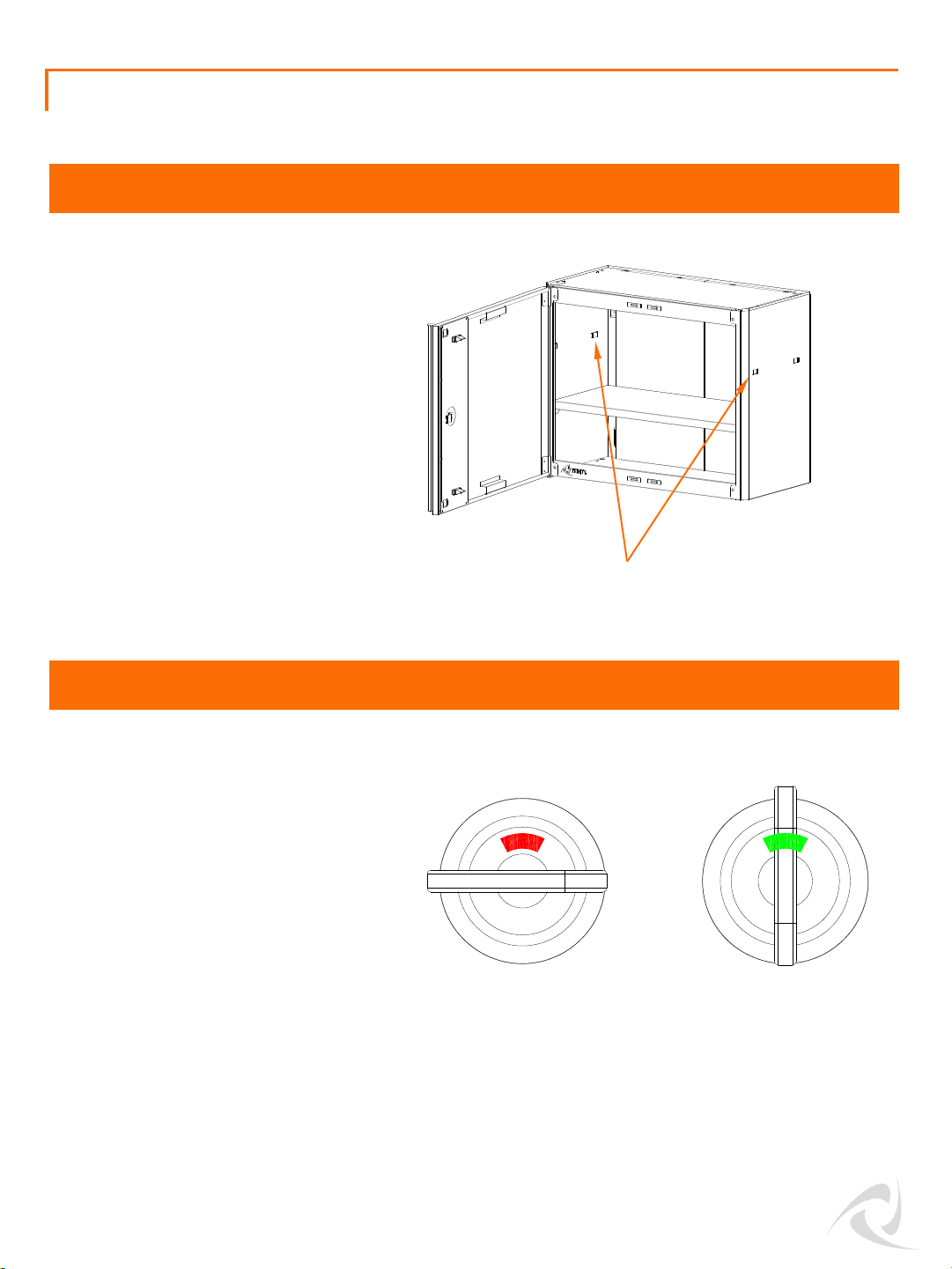
SHELF ADJUSTMENT
Position Tabs
LOCK AND UNLOCK
Insert the key into the lock on the right
door. Turn it clockwise 90 degree to lock
the door. Turn it counter-clockwise 90
degree to unlock the door.
Before locking the unit, make sure the
doors are fully closed.
Ensure all products have been removed
from the shelf.
To adjust the shelf, take the shelf out of
the cabinet and re-attach the shelf
supports to the position tabs at your
desired height.
Tilt the shelf diagonally to move it inside
the cabinet. Place the shelf on top of all
four shelf supports.
Red indicates locked
Green indicates unlocked
Page 8
7
© 2018 TRINITY - 800.985.5506
SERVICE PARTS LIST – TLSPBK-0604
Part Number Description Part Number Description
1)
PBK
-16-004-2411
Top Panel
9)
PBK
-08-008-2319
Door
2)
PBK
-18-018-2412
Cabinet Body
10)
AMA
-05-019-1850
Door Handle
3)
XBK
-02-001-0003
Magnetic Catcher
11)
PBK
-09-012-0001
Door Hinge
-G
4)
PBK
-03-052-2410
Shelf
12)
XBK
-01-004-0612
Black Screw
5)
XSV
-02-017-0001
Shelf Support
13)
PBK
-19-005-2402
Wall Bracket
6)
PBK
-16-003-2411
Bottom Panel
14)
ZSV
-01-003-0530
Mounting Screw
7)
XBK
-10-001-0XXX
Key
15)
XWH
-01-032-0630
Anchor
8)
PBK
-09-011-0001
Door Hinge
-F
TRINITY Customer Service provides the following replacement parts:
2
1
3
5
7
9
11
4
12
13
14
68
10
15
 Loading...