

Page 1

®
SS180 TMA
(Model 9182)
.
Product Description
Assembly Manual
Revision B June 2013Part No. 115359B
Page 2

SS180 TMA®
(Model 9182)
Product Description
Assembly Manual
2525 Stemmons Freeway
Dallas, Texas 75207
Important
assembly, maintenance, and repair of SS180 TMA
are for standard assemblies specified by the appropriate highway authority only.
In the event the specified system assembly, maintenance, or repair would
require a deviation from standard assembly parameters, contact the appropriate
highway authority engineer. This system has been accepted by the Federal
Highway Administration for use on the national highway system under strict
criteria utilized by that agency. Energy Absorption Systems representatives are
available for consultation if required.
: These instructions are to be used only in conjunction with the
®
systems. These instructions
This Manual must be available to the worker overseeing and/or assembling the product
at all times. For additional copies, contact Energy Absorption Systems at (888) 323-6374
or download from websites below.
The instructions contained in this Manual supersede all previous information and Manuals. All
information, illustrations, and specifications in this Manual are based on the latest SS180 TMA
system information available to Energy Absorption Systems at the time of printing. We reserve
the right to make changes at any time. Please contact Energy Absorption Systems to confirm
that you are referring to the most current instructions.
Part No. 115359B
www.energyabsorption.com Revision B June 2013
www.highwayguardrail.com 1 All rights in copyright reserved
®
Page 3

Table of Contents
Customer Service Contacts ......................................................................................................... 3
Important Introductory Notes ....................................................................................................... 3
System Overview ......................................................................................................................... 4
Recommended Safety Rules for Assembly ................................................................................. 4
Safety Symbols ............................................................................................................................ 5
Warnings and Cautions ............................................................................................................... 5
Limitations and Warnings ............................................................................................................ 6
Know Your SS180 TMA
Assembly ................................................................................................................................... 12
Preparation .......................................................................................................................... 13
Operation Instructions ............................................................................................................... 27
Folding and Unfolding the System ....................................................................................... 27
Maintenance .............................................................................................................................. 28
I. Routine Maintenance ........................................................................................................ 28
II. Detaching and Attaching the System to the Truck ........................................................... 30
III. Lubrication ...................................................................................................................... 32
IV. Technical Specifications ................................................................................................. 33
Repair Instructions ..................................................................................................................... 34
Post Impact .......................................................................................................................... 34
Troubleshooting Guide .............................................................................................................. 40
Hydraulic Fluid ..................................................................................................................... 41
Hydraulic System ................................................................................................................. 42
Pressure Relief Valve .......................................................................................................... 44
Counterbalance Valve ......................................................................................................... 44
Hydraulic Cylinders .............................................................................................................. 46
Hydraulic System Priming ................................................................................................... 47
Reservoir ............................................................................................................................. 47
Electrical Problems .............................................................................................................. 48
Troubleshooting Decision Trees .......................................................................................... 50
SS180 TMA
®
9182 .................................................................................................................... 53
Support Frame Assembly, 9182 ................................................................................................ 55
Hydraulic Assembly, 9182 ......................................................................................................... 56
Hydraulic Pump Assembly, 9182 ............................................................................................... 58
Electrical Box Hydraulic Pump .................................................................................................. 59
Underride Assembly Receiver, TMA ......................................................................................... 60
Attachment Assembly, 9180 ...................................................................................................... 61
Support Frame Preassembly, 9182, 24V .................................................................................. 62
Lighting/Wiring Assembly, 9182 ................................................................................................ 65
Support Frame Assembly, 8291 ................................................................................................ 68
Hydraulic Cylinder Assembly, 9182 ........................................................................................... 69
®
System ................................................................................................ 7
www.energyabsorption.com Revision B June 2013
www.highwayguardrail.com 2 All rights in copyright reserved
Page 4

Customer Service Contacts
Energy Absorption Systems (a Trinity Highway Products company) is committed to the highest
level of customer service. Feedback regarding the SS180 TMA
®
system, its assembly
procedures, supporting documentation, and performance is always welcome. Additional
information can be obtained from the contact information below:
Energy Absorption Systems:
Telephone:
E-mail: [email protected]
Internet: Energy Absorption Systems
Trinity Highway Products, LLC
(888) 323-6374 (USA Only)
(214) 589-8140 (USA or International)
http://www.energyabsorption.com
http://www.highwayguardrail.com
Important Introductory Notes
Proper assembly of the SS180 TMA® system is essential to achieve performance of the system
under appropriate federal and state criteria. These instructions should be read in their entirety
and understood before assembling the SS180 TMA
only in conjunction with the assembly of the SS180 TMA
assemblies only as specified by the applicable highway authority. In the event your system
assembly requires or involves deviation from standard parameters or, during the assembly
process a question arises, please contact the appropriate highway authority that specified this
system at this particular location for guidance. Energy Absorption Systems is available for
consultation with that agency. These instructions are intended for an individual who is qualified
to both read and accurately interpret them as written. They are intended for the individual who
is experienced and skilled in the assembly of highway products which are specified and
selected by the highway authority. If there are deviations, alterations, or departures from the
assembly protocol specified in this Manual, the device may not perform as it was tested and
accepted.
®
system. These instructions are to be used
®
system and are for standard
A set of product drawings will be supplied by Energy Absorption Systems, when requested.
The drawings will be for each section of the assembly. These drawings should be reviewed and
studied thoroughly by a qualified individual who is skilled in interpreting them before the start of
any assembly.
www.energyabsorption.com Revision B June 2013
www.highwayguardrail.com 3 All rights in copyright reserved
Page 5
System Overview
The SS180 TMA® system is a Truck Mounted Attenuator (TMA) shown to reduce the risk of
injury to passengers of an errant vehicle and to the driver of the truck to which the system is
attached when the system is impacted within the applicable NCHRP 350 criteria. The system
mounts on the rear of a truck and may be used in stationary applications (e.g. as a truck block
in a work zone) and mobile operations (e.g. striping, sweeping, plowing, etc.).
Important: Read safety instructions thoroughly and follow the assembly
directions and suggested safe practices before assembling, maintaining, or
repairing the SS180 TMA
serious injury or death to the worker and/or bystanders. It further compromises
the acceptance of this system by the FHWA. Please keep these instructions for
later use and reference by anyone involved in the assembly of the product. Use
the traffic control plan set for the by the highway authority in charge of this work
area.
®
system. Failure to follow this warning can result in
Warning: Ensure that all of the SS180 TMA
Important Statements within the SS180 TMA
®
system Warnings, Cautions, and
®
Manual are completely followed.
Failure to follow this warning could result in serious injury or death in the event
of a collision.
Recommended Safety Rules for Assembly
* Important Safety Instructions *
This Manual must be kept in a location where it is readily available to persons who are skilled
and experienced in the assembly, maintenance, or repair of the SS180 TMA
Additional copies of this Manual are immediately available from Energy Absorption Systems by
calling (888) 323-6374 or by email at [email protected]. This Manual
may also be downloaded directly from the websites indicated below. Please contact Energy
Absorption Systems if you have any questions concerning the information in this Manual or
about the SS180 TMA
Always use appropriate safety precautions when operating power equipment, mixing
chemicals, and when moving heavy equipment or the SS180 TMA
®
system.
®
system components.
Gloves, safety goggles, safety toe shoes, and back protection shall be used.
Safety measures incorporating traffic control devices specified by the highway authority must
be used to provide safety for personnel while at the assembly, maintenance, or repair site.
®
system.
www.energyabsorption.com Revision B June 2013
www.highwayguardrail.com 4 All rights in copyright reserved
Page 6
Safety Symbols
This section describes the safety symbols that appear in this SS180 TMA® Manual. Read the
Manual for complete safety, assembly, operating, maintenance, repair, and service information.
Symbol Meaning
Safety Alert Symbol: Indicates Danger, Warning, Important, or Caution.
Failure to read and follow the Danger, Warning, Safety, or Caution indicators
could result in serious injury or death to worker(s) and/or bystanders.
Warnings and Cautions
Read all instructions before assembling, maintaining, or repairing the SS180 TMA® system.
Warning: Do not assemble, maintain, or repair the SS180 TMA
®
system until
you have read this Manual thoroughly and completely understand it. Ensure that
all Warnings, Cautions, and Important Statements within the Manual are
completely followed. Please call Energy Absorption Systems at (888) 323-6374
if you do not understand these instructions. Failure to follow this warning could
result in serious injury or death in the event of a collision.
Warning: Safety measures incorporating appropriate traffic control devices
specified by the highway authority must be used to protect all personnel while at
the assembly, maintenance, or repair site. Failure to follow this warning could
result in serious injury or death in the event of a collision.
Warning: Use only En ergy Absorption Systems parts that are specified herein
for the SS180 TMA
®
TMA
system. Do not utilize or otherwise comingle parts from other
systems even if those systems are other Energy Absorption Systems or
Trinity Highway Products systems. Such configurations have not been tested,
nor have they been accepted for use. Assembly, maintenance, or repairs using
unspecified parts or accessories is strictly prohibited. Failure to follow this
warning could result in serious injury or death in the event of a vehicle impact
with an UNACCEPTED system.
Warning: Do NOT modify the SS180 TMA
follow this warning could result in serious injury or death in the event of a
collision.
®
system for assembling, maintaining, or repairing the SS180
®
system in any way. Failure to
Warning: Ensure that the SS180 TMA
®
system and delineation used meet all
federal, state, specifying agency, and local specifications. Failure to follow this
warning could result in serious injury or death in the event of a collision.
Warning: Ensure that your assembly meets all appropriate Manual on Uniform
Traffic Control Devices (MUTCD) and local standards. Failure to follow this
warning could result in serious injury or death in the event of a collision.
www.energyabsorption.com Revision B June 2013
www.highwayguardrail.com 5 All rights in copyright reserved
Page 7

Limitations and Warnings
Energy Absorption Systems, in compliance with the National Cooperative Research Highway
Program 350 (NCHRP Report 350) “Recommended Procedures for the Safety Performance of
Highway Safety Features”, contracts with FHWA approved testing facilities to perform crash
tests, evaluation of tests, and submittal of results to the Federal Highway Administration for
review.
The SS180 TMA
of NCHRP Report 350. These tests, specifically set forth by FHWA, evaluate product
performance by simulating those impacts outlined by NCHRP Report 350 involving a typical
range of vehicles on our roadways, from lightweight cars (approx. 820kg [1800 lb.]) to full size
pickup trucks (approx. 2000 kg [4400 lb.]) as specified by the FHWA. A product can be certified
for multiple Test Levels. The SS180 TMA
Test Level 3: 100 km/h [62 mph]
These FHWA directed tests are not intended to represent the performance of systems
when impacted by every vehicle type or every impact condition existing on the roadway.
This system is tested only to the test matrix criteria of NCHRP 350 as approved by
FHWA.
Energy Absorption Systems does not represent nor warrant that the results of these controlled
tests show that vehicle impacts with the products would necessarily avoid injury to person(s) or
property. Impacts that exceed the specifications of the system may not result in acceptable
crash performance as outlined in NCHRP Report 350, relative to structural adequacy, occupant
risk and vehicle trajectory. Energy Absorption Systems expressly disclaims any warrant or
liability for injury or damage to persons or property resulting from any impact, collision, or
harmful contact with products, other vehicles, or nearby hazards or objects by any vehicle,
object or person, whether or not the products were installed by or under the direction of Energy
Absorption Systems or by third parties.
SS180 TMA
with specific State and Federal guidelines. Energy Absorption Systems offers a reflective
delineator panel for its TMA line of products. However, the material is only intended to
supplement delineation required by the Department of Transportation’s “Manual on Uniform
Traffic Control Devices” (MUTCD). The appropriate highway authority approved engineer
should be careful to properly select, assemble, and maintain the product. Careful evaluation of
the speed, traffic direction, and visibility are some of the elements that require evaluation in the
proper selection of a safety appurtenance by the appropriate specifying highway authority.
®
system was tested to meet the impact criteria, requirements, and guidelines
®
is certified to the Test Level as shown below:
®
system is intended to be assembled, delineated, and maintained in accordance
After an impact occurs, the product must be repaired to its original condition as soon as
possible. When a safety product is impacted, it is mandatory that the highway authority inspect
all the components for damage and repair and/or replace components as necessary. If the
system is not repairable, a complete system replacement is required.
www.energyabsorption.com Revision B June 2013
www.highwayguardrail.com 6 All rights in copyright reserved
Page 8
Know Your SS180 TMA® System
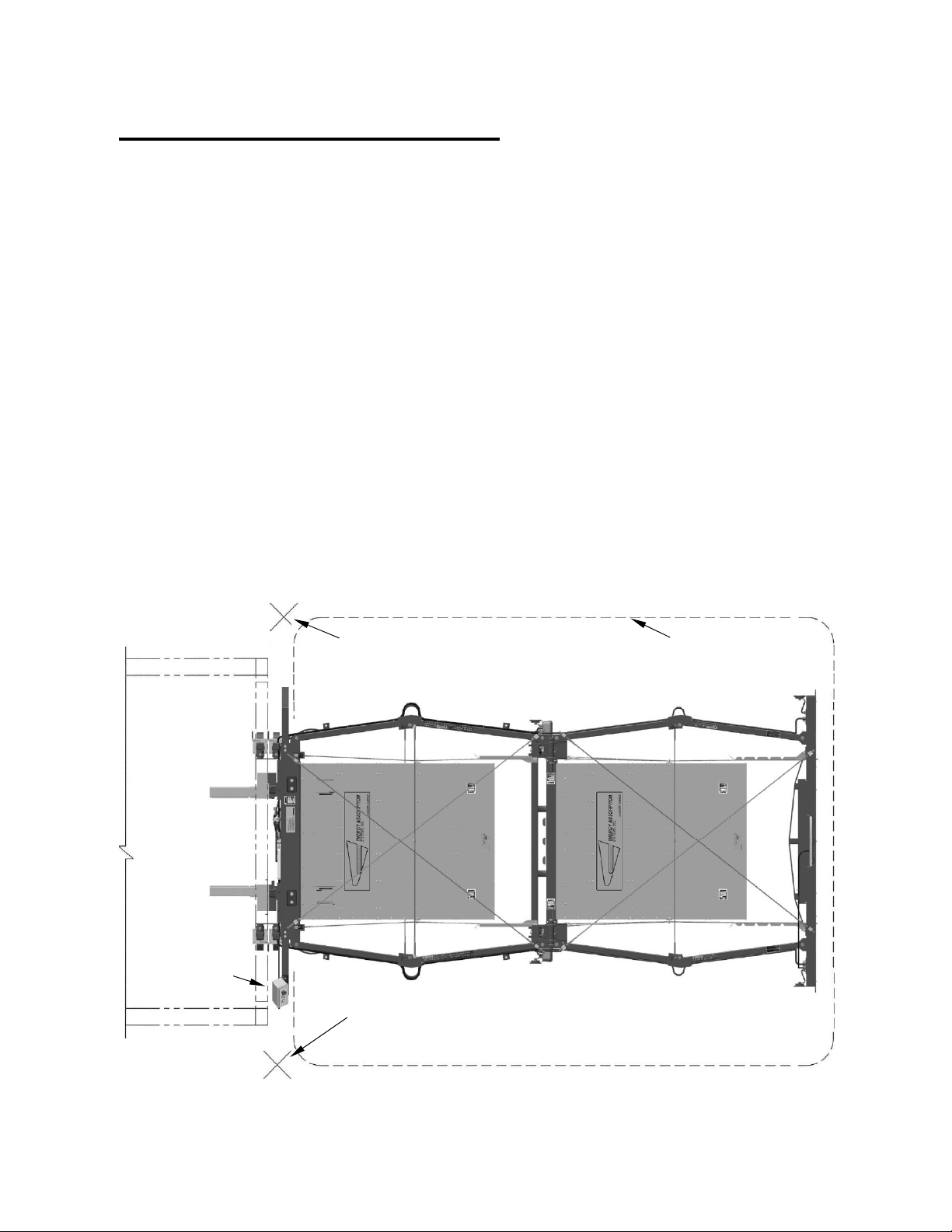
For the safety of the operator, the operator shall stand at the rear of the truck, on the curb side,
(See Figure 2). When tilting the TMA, care shall be taken to stay clear of all moving parts.
Figure 1
TRUCK
CONTROLS
STAND HERE (FOR CONTROLS
ON RIGHT SIDE OF TRUCK)
CONTROLS CAN BE ON EITHER
SIDE OF TRUCK
CARTRIDGE
STAND HERE (FOR CONTROLS
ON LEFT SIDE OF TRUCK)
CONTROLS CAN BE ON EITHER
SIDE OF TRUCK
Figure 2
MOVING PARTS DURING FULL
DESIGN IMPACTS AND
FOLDING OPERATION
CARTRIDGE
www.energyabsorption.com Revision B June 2013
www.highwayguardrail.com 7 All rights in copyright reserved
Page 9

1. The TMA shall be rigidly fastened to the truck. In the horizontal position, the bottom of
the TMA shall be 280 to 330 mm [11" to 13"] from the ground and level (See Figure 3).
The TMA must be left in the unfolded position whenever possible. The TMA can only
absorb the energy of an impacting vehicle when in the unfolded position.
Figure 3
2. Jacks shall be used to support the TMA when it is detached from the truck. The Jacks
must be stored while the TMA is attached to the truck. The Jacks can be stored on the
brackets provided on the support frame (See Figure 3).
3. Make sure all pivot pins are in position and that all retaining pins are assembled
correctly (See Figure 4).
Figure 4
The SS180 TMA® shall be deployed in the unfolded position: At all times while operating as
either a Barrier Vehicle or Shadow Vehicle.
®
The SS180 TMA
low speed, transporting at a speed much lower than adjacent traffic, and transporting in areas
where vehicle ride characteristics and maneuverability are maintainable.
The SS180 TMA
speed, transporting at a speed near the speed of adjacent traffic, and transporting under
conditions of compromised maneuverability typically when the large turning radius clearance
needed for the extended TMA is not safe.
www.energyabsorption.com Revision B June 2013
www.highwayguardrail.com 8 All rights in copyright reserved
shall be in the "unfolded" position when: transporting short distances at a
®
shall be in the "folded" position when: transporting long distances at a high
Page 10

®
4. The SS180 TMA
is intended to support its own weight and dissipate the kinetic energy
of errant vehicles per NCHRP 350 criteria. Do not drag the TMA or place anything on its
top or damage will result. Do not sit, stand or lean on any part of the TMA (See Figures
5 & 6).
Figure 5
Figure 6
5. Before raising or lowering the TMA, the operator shall be fully trained as to its proper
operation. All operators shall fully understand the contents of this Manual prior to
operating the system. The operator should never stand under the TMA when it is
raised, or attempting to lower it.
6. Folding the TMA provides the best maneuverability and driving characteristics. It is
advisable, during restricted city driving and high-speed travel, to have the TMA folded to
its storage position. Refer to local agency policies as required for additional guidance.
Unfold the system either before, or as soon as possible after, entering a job site or
beginning shadow vehicle operations. It is required that the support vehicle be stopped
for TMA folding and unfolding.
7. Be sure all persons are standing clear before folding or unfolding the TMA. Be sure the
system is stopped in full folded position before allowing anyone directly behind the
folded system.
www.energyabsorption.com Revision B June 2013
www.highwayguardrail.com 9 All rights in copyright reserved
Page 11
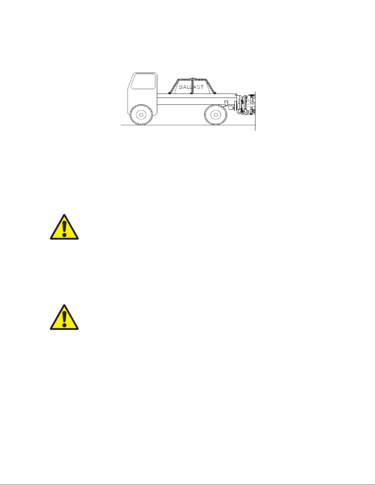
8. Ballast and other heavy objects MUST BE ADEQUATELY ANCHORED to the truck to
prevent shifting during an impact (See Figure 7). The force exerted on the tie-down
straps could be 20 times the weight of the ballast.
Figure 7
9. The agency responsible for the truck shall inspect it for adequate operator safety
equipment (e.g., seat belts, head rests, etc.)
®
10. It is recommended that the SS180 TMA
[16,090 lbs.] or greater.
11. Make sure that the performance and safety of the TMA is not impaired by damage or
corrosion.
be mounted to trucks weighing 7300 kg
Warning:
Failure to comply with these instructions can result in unpredictable
TMA performance and possible personal injury or death. This TMA is intended
to be used as an impact attenuator on the rear of trucks which meet the
specifications for this system. The TMA shall not be used for any other purpose.
12. Regular maintenance of the TMA is critical for proper operation. Refer to the
maintenance section of this Manual for additional information.
Regular inspection of frame members, cartridges, and pins is necessary to ensure
proper system performance.
Regular inspection of hydraulic hoses is critical. A broken or damaged hose will
cause the system to operate uncontrollably.
Warning:
In the event of a hydraulic pressure loss during operation, release
button and repair immediately (REPEAT whenever necessary).
Keep electrical connections at the Pump Motor/Solenoid clean to prevent arcing.
Clean any hydraulic spills or leakage to prevent bodily injury, fire, etc.
13. The driver shall be cautious while making turns with the TMA in the unfolded position.
The TMA extends beyond the end of the truck and will swing wide while turning.
14. This system is an impact attenuator and is therefore used in high risk areas. Stay clear
of traffic whenever possible. If the system is impacted, there may be fragments from the
truck, TMA, or impacting vehicle that could cause injury.
www.energyabsorption.com Revision B June 2013
www.highwayguardrail.com 10 All rights in copyright reserved
Page 12

15. The Hydraulic Assembly was designed to fold and unfold the TMA system as intended.
Any other use may be hazardous to people or equipment.
Do not use the system to push a load.
Do not use the raised end of the system to support any load.
Do not use any part of the TMA for towing or hauling a load. This could cause the lift
mechanism to malfunction and permanently damage the system.
Do not use the TMA as a ladder.
16. The system must be in the unfolded position to perform properly during an impact. Do
not leave the system raised, even slightly, when positioned at a job site.
17. Be sure the truck meets the minimum requirements for attaching a TMA (See the
assembly section for further details).
Definitions: The BARRIER VEHICLE is the truck on which a TMA is mounted, while
positioned upstream (towards the direction that traffic is approaching) of a work zone.
The SHADOW VEHICLE is the truck on which a TMA is mounted, which is following behind a
moving operation such as striping, spraying, etc.
THE USE OF A TMA ON THE BACK OF A TRUCK
WILL:
Gradually decelerate the impacting vehicle
Help protect the occupants of the impacting vehicle
Help protect the barrier/shadow vehicle occupants
Help reduce damage to the barrier/shadow vehicle
WILL NOT:
Affect the skid (roll ahead) distance of an impacted truck.
KEEP WORK CREWS CLEAR!
CONTROLLING SKID DISTANCE (ROLL AHEAD):
Skid distance is significantly increased and is less predictable for lightweight
shadow vehicles.
Skid distance is reduced and is more consistent when heavier shadow vehicles are
used.
Required Truck + TMA weight: 8250 kg [18,190 lbs.] or greater
www.energyabsorption.com Revision B June 2013
www.highwayguardrail.com 11 All rights in copyright reserved
Page 13

Assembly
Read and understand all instructions before beginning assembly.
The weight of the vehicle shall be between 7300 kg [16,090 lbs. or greater] for tested
performance.
The system must be attached to the truck by welding parts to the frame. Do not weld forward of
the rear leaf spring hangers to ensure structural integrity of frame. Use AWS qualified welders
to ensure durable attachment of the TMA system. Disconnect the truck battery before any
welding on truck or TMA.
The truck frame must be suitable and accessible for mounting a TMA system. If there are any
questions regarding the suitability, contact the Customer Service Department for input as to
your specific application.
1) Shipping list
Check the shipping list against the actual parts to make sure all items were received.
2) Assemble Necessary tools:
Recommended Tools
Welding equipment (for 1/2” plate) GMAW or SMAW
Cutting torch
Hammer
Drift pin or alignment pin (12” long)
Tape measure
1/2” drive socket wrench w/6” extension
1/2” drive sockets (9/16”, 1-1/8”, 1-1/2”, 9/16” deep well)
Open end wrenches –(9/16”, 1-1/8”, 1-1/2”)
12” crescent wrenches – (2)
Marking implement (pencil, soap stone)
Floor jack
Drill for 13/16" diameter bit
13/16" diameter bit and pilot drill bit for same
Center punch
Torque wrench - 120 N-m [90 ft-lb]
Hydraulic fluid (use Dexron
Forklift
Work gloves and other personal protection equipment as required
Bubble level
®
III fluid only) - Shipped with system
Note: The above list of tools is a general recommendation. Depending on specific site
conditions and the complexity of the assembly specified by the appropriate highway
authority, additional or fewer tools may be required. Decisions as to what tools are
needed to perform the job are entirely within the discretion of the specifying highway
authority and the authority’s selected contractor performing the assembly of the system
at the authority’s specified assembly site.
www.energyabsorption.com Revision B June 2013
www.highwayguardrail.com 12 All rights in copyright reserved
Page 14

Preparation
3A) Assembly Must Be Performed On A Level Surface
The system’s framework is very heavy and pivots in several areas. Until the framework is
secured with the cables and trigger bolts, it can swing out in an approximate 4 m [13’] radius
from either side of the truck. A level surface is required to maintain control of the framework
when it is being extended to its full length.
3B) Truck ballast
Use a bubble level to verify that the truck is parked on a level surface. The truck shall be as
close to the final driving weight as possible. If ballast must be added to achieve the 7300 kg
[16,090 lbs.] minimum weight, add it at this time. Ballast must be properly anchored to the truck
to keep it in place during an impact. Ideally, an adequately sized truck, that requires no ballast,
should be used. Because the 943 kg [2080 lbs.] weight of the rearward protruding TMA is
supported by the back of the shadow vehicle, care must be taken not to exceed the
manufacturer's published maximum axle loads. To ensure that the driving characteristics of the
vehicle are maintained, the manufacturer’s recommended center-of-gravity zone shall be
followed completely.
4) Check for interference
Before attempting to assemble the Underride, check for interference concerns.
The System folds such that the Impact Face is very close to the mounting location (See Figure
30 Page 33). If you are using something other than a standard Socket Receiver Hitch
Underride refer to special instructions supplied with your assembly then skip to Step 8.
Temporarily position the Underride Socket Receiver under truck frame as shown (See Figure
12) and check for interference concerns. Interference concerns with tail lights, springs, dump
bodies (in the folded or unfolded positions), etc., shall be corrected before proceeding.
Figure 8
www.energyabsorption.com Revision B June 2013
www.highwayguardrail.com 13 All rights in copyright reserved
Page 15

5) Underride Assembly
With the truck at its actual driving weight and parked on a level surface, measure the distance
from the ground to the bottom of the truck frame. A distance of 711±25 mm [28±1"] is required.
Spacers may be added to the bottom of the frame to achieve this height (See Figure 11
Underride Assembly drawing on Page 15).
Note:
50 mm [2"]. Adjust the height to compensate for anticipated settling.
Measure distance from the back end of the frame forward to the rear-most leaf spring hanger.
Look for any obstruction on the bottom of the frame that may interfere with the Socket
Receiver. A minimum of 305 mm [12"] is required (See the Underride Assembly drawing on
Page 15).
Position the Socket Receiver at the rear end of the frame so that the 76 x 387 mm
[3” x 15-1/4"] flat bar is along the outside of the frame member and the Socket Receiver
Assembly is flush with the end of frame. If spacers are required, weld them to the Socket
Receiver and lap the Spacer Splices (pieces of 10 x 51 x 103 mm [3/8” x 2” x 4"] flat bar)
across the Socket Receiver and Spacer at the rear-most location (See Underride Assembly
drawing). The top of the Socket Receiver shall be 711±25mm [28±1”] from the level ground for
proper system height (See Figure 12).
Weld the Socket Receiver to the bottom of the truck frame with the 76 x 387 mm [3” x 15-1/4”]
flat bar on the outer side of the frame (See Figure 11).
Note:
in accordance with the Underride drawing. Disconnect truck battery before welding.
The truck’s springs may settle with the weight of the TMA, sometimes as much as
All welding must be performed by a welder certified to AWS D14.3-82 or AWS D1.1
Caution
or apply excessive heat, to the bottom flange, forward of rear-most leaf spring
hangers.
:
The truck frame is high carbon steel. To avoid cracking, do not weld,
Figure 9 Figure 10
www.energyabsorption.com Revision B June 2013
www.highwayguardrail.com 14 All rights in copyright reserved
Page 16

Note: Left and right Underride Socket Receivers
must be parallel with each other and level.
711 mm ± 25 mm [28± 1”]
Figure 11 Socket Hitch (Left Side Shown)
www.energyabsorption.com Revision B June 2013
www.highwayguardrail.com 15 All rights in copyright reserved
Page 17

6) Socket Hitch Assembly
Assemble the Socket Hitches and pin them into place using the 1” x 6-1/4" Hitch Pins and
Retainer Pins shipped with the system.
Figure 12
7) Mount the Support Brackets to Socket Receivers
Mount the Support Brackets to the Socket Hitches as shown in Figure 13. Shims are used to
level the system. It is recommended that 1/2" Shims be used initially. This may be adjusted
once the system is assembled.
Figure 13
www.energyabsorption.com Revision B June 2013
www.highwayguardrail.com 16 All rights in copyright reserved
Page 18

8) Attach the Support Frame / Backup to the Attachment Assembly
Move the system to the truck and pin the Support Frame/Backup Assembly to the Support
Brackets (See Figure 14). The system is to be assembled while the Support Frame is collapsed
and forklift slings are supporting the system. Use the upper set of mounting holes for the
attachment.
Figure 14
www.energyabsorption.com Revision B June 2013
www.highwayguardrail.com 17 All rights in copyright reserved
Page 19

9) Extend the Support Frame
With the TMA pinned to Attachment Assembly, slowly and evenly pull the frame out to its full
extent.
Warning:
extreme care.
Warning:
Until the cables are assembled, the system may shift to one side.
Even when supported by forklift, frame can be unwieldy. Use
Figure 15
www.energyabsorption.com Revision B June 2013
www.highwayguardrail.com 18 All rights in copyright reserved
Page 20

10) Assemble the Bottom Release Cable across the Arm Assemblies
Verify that the Support Frame is fully extended. Assemble the Bottom Release Cable across
Arm Assemblies (See Figure 16). Torque the nuts to 34±3 N-m (25±2 ft-Ib/300±24 in-lb)
making sure that roughly an equal amount of threads protrude from nuts on both ends of cable.
Lock cable in place using remaining fasteners as "jam" nuts.
TORQUE TO 34 N-m (-0, +3) [25 ft - Ib (-0, +2)]
RELEASE CABLE
TORQUE TO 34 N-m (-0, +3) [25 ft - Ib (-0, +2)]
Figure 16
www.energyabsorption.com Revision B June 2013
www.highwayguardrail.com 19 All rights in copyright reserved
Page 21

11) Assemble Cartridges
Remove one end of each Alignment Cable from the TMA and set aside to clear the top side of
each bay. Using a forklift and sling, place Cartridge B in position and secure it using the flat
washers, lock washers and nuts provided. Torque the nuts to 120±7 N-m (90±5 ft-lb /
1080±30 in-lb). Repeat procedure for Cartridge A (See Figure 17).
12) Assemble the Top Release Cables across the Arm Assemblies
Verify that the Support Frame is extended as far as it will go. Assemble the Bottom Release
Cable across Arm Assemblies (See Figure 16). Torque the nuts to 34±3 N-m (25±2 ft–lb /
300±24 in-lb) making sure that roughly an equal amount of threads protrude from nuts on both
ends of cable. Lock cable in place using remaining fasteners as “jam” nuts.
Figure 17
www.energyabsorption.com Revision B June 2013
www.highwayguardrail.com 20 All rights in copyright reserved
Page 22

13) Assemble and Adjust the Alignment Cables
There are four Alignment Cables (two for each Bay). Attach the Alignment Cables as shown in
Figure 18. Measure the diagonals of each bay and adjust the cables so that the diagonal
measurements in each bay are the same within the given tolerance (A = B±5 mm [3/16"], C =
D ± 5 mm [3/16"]) and taut. Cables are "taut" when they deflect 38 mm – 50 mm [1 1/2"-2"]
when pressed by hand at the midpoint. Lock each cable in place using the second nut as a
“jam nut”.
14) Assemble and Tension the Cartridge Support Cables
There are six Cartridge Support Cables. Assemble the cables as shown in Figure 19.
Attach thimble end of all Cartridge Support Cables to the intermediate frame using the provided
shackles. Pass the stud end of the cable through the corresponding Cartridge Chain Loop, and
attach as shown in Figure 19 using a die spring, washer and nuts.
To properly tension the Cartridge Support Cables, tighten the first nut on one cable until all
slack is removed, then tighten it until the tensioning springs have been compressed to 32 mm ±
2 mm [1 1/4” ± 1/16”] in height. Lock this nut in place with the second "jam" nut. Repeat this
procedure with the other cables.
Figure 18
www.energyabsorption.com Revision B June 2013
www.highwayguardrail.com 21 All rights in copyright reserved
Page 23

15) Assemble Side Guides
/
There are four Side Guides, two for Bay 1 and two for Bay 2. Attach guides as shown in Detail
19b and tighten bolts.
16) Adjust the Height and Levelness of the System Frame
Verify that the system frame is 305±25 mm [12"±1"] from the ground at the front and rear of the
system. It may be necessary to add shims to the Socket Hitch in order to adjust the levelness
of the Cartridge (See Figures 19 & 19a).
Detail 19a Detail 19b
SEE DETAIL 19a
CARTRIDGE SUPPORT CA BLE
32 mm ± 2 mm [1 1
SHACKLE
CARTRIDGE
SUPPORT CABLE
305 mm ± 25 mm [12” ± 1] 305 mm ± 25 mm [12” ± 1]
INTERMEDIATE FRAME
Figure 19
4 ± 1/16]
WASHER
NUTS
SIDE GUIDE
SEE DETAIL 19b
www.energyabsorption.com Revision B June 2013
www.highwayguardrail.com 22 All rights in copyright reserved
Page 24

17) Connect the Lights and Controls
Locate the female TMA Socket Connector in a convenient location on the truck, so that lifting or
lowering the TMA will not damage the electrical cable. Make sure that the electrical cord on the
TMA can reach this location.
For support vehicles with combined tail and clearance lights, connect a jumper between pins 2
and 6 on the backside of the male TMA plug connector (see VIEW A-A Figure 20). Connect the
7-pin plug to the socket on the truck.
®
The truck battery must be of the proper voltage. The SS180 TMA
volt versions. Be sure the system and truck are compatible. Be sure to use standard safety
practices when attaching the battery cables (e.g. do not let the ends of the cables touch, etc).
Do not run the battery cables around sharp corners or metal work, or in other areas that would
pinch or cut the cables. Connect the battery cable to the pump motor (see the Hydraulic
Assembly in drawing package).
The controls at the rear of the truck shall be mounted to the Support Frame, on the non-traffic
side (side closest to the curb). If they are not, move the rocker switch to the other side by
compressing the four tabs on the back side of the switch towards the switch body. Securely
fasten cable ties to secure any loose wiring to the TMA frame. Mount the cab switch box inside
the cab within easy reach of the driver and plug in the cab switch box at the mating connector
of the TMA.
is available in 12 volt and 24
Figure 20
www.energyabsorption.com Revision B June 2013
www.highwayguardrail.com 23 All rights in copyright reserved
Page 25

18) Check the Hydraulic System
The Hydraulic Assembly is pre-assembled and tested for operation and leaks before shipping.
The pump is wired as shown on the Hydraulic Assembly drawing. Before operating the system,
remove the vent plug from the fill port of the hydraulic pumps reservoir and check to see if the
reservoir is full (the fluid should be just visible). Add only Dexron
overfill. Replace the vent plug in the filler port. (Be careful not to cross thread it.)
Read Operation Instructions (See Page 27; Folding and Unfolding the System). Making sure all
electrical and hydraulic lines will not be damaged, use the switch at the rear of the truck to fold
and unfold the system twice. This purges air from the system and verifies operation.
Also, cycle the system using the cab switches to verify proper operation.
®
III ATF fluid if it is not. Do not
Figure 21
Note:
Continuous operation may run down truck battery or damage pump.
Important:
Ensure both positive and ground cables are connected directly
from pump to battery. DO NOT rely on chassis or frame for proper grounding.
www.energyabsorption.com Revision B June 2013
www.highwayguardrail.com 24 All rights in copyright reserved
Page 26

19) Store the Jacks
The Jacks are provided to facilitate the attachment and removal of a folded SS180 TMA® from
the truck. Retrieve Jacks set aside earlier and place them in the storage positions as shown in
Figure 22.
Figure 22
Warning
TMA is in service.
: Jacks are to be removed from Arm Assemblies and stored when
20) Check System Lights for Proper Operation
Verify that all the turn / stop / tail / reverse lights are working properly. Replace any bulbs that
are out.
®
There are two light circuits on the SS180 TMA
Raise the system to the folded position and verify secondary lights are working.
With the system unfolded, lights on the Impact Face will be on and lights on the Mid-Frame will
be off.
With the system folded, the lights on the Mid-Frame will be on and the lights on the Impact
Face will be off.
www.energyabsorption.com Revision B June 2013
www.highwayguardrail.com 25 All rights in copyright reserved
. Verify both circuits are operational.
Page 27

21) Verify the Position of the Hydraulic/Electrical Lines
Check the location of all the hydraulic and electrical lines to be sure they will not be damaged
during folding and unfolding of the system.
22) Final Check of System
Check the tightness of all of the fasteners. Double check the height and levelness of the
system.
23) Ready to Use
The SS180 TMA® system is now ready for use. To ensure proper and safe operation, all
SS180 TMA
®
users shall be given operating and safety training, as given in this Manual and as
specified by the owner and local regulations.
www.energyabsorption.com Revision B June 2013
www.highwayguardrail.com 26 All rights in copyright reserved
Page 28

Operation Instructions
Before operating the SS180 TMA®, thoroughly read and understand all Operation Instructions
and safety sections of this Manual. Verify that the system is properly assembled and in working
order. For proper impact performance, the TMA must be equipped with one SS180 TMA
A Cartridge and one SS180 TMA
®
Type B Cartridge, in their proper positions as shown in
Figure 17 on Page 20.
®
The SS180 TMA
has been equipped with a Hydraulic Pump that can be used to fold the TMA
from its extended position. The controls are located on one side of the Support Frame. A set of
controls may also be located in the truck cab. The controls on the Support Frame shall be
mounted to the non-traffic side of the system. To change the mounting, see "Connect the
Lights and Controls" section in this Manual.
While folding or unfolding the SS180 TMA
®
from outside the cab, the operator must stand on
the non-traffic side of the truck. Always stay clear of moving parts. Never stand underneath the
TMA.
Folding and Unfolding the System
Caution: Make sure the area above and behind the system is clear of all
objects before proceeding. Under no circumstances shall anyone be allowed
behind the system when it is being folded or unfolded. When operating from
the cab, always be aware of objects behind and above the SS180 TMA
®
Type
®
.
Folding and unfolding the system: The Rocker Switch operates by pushing and holding the
switch down on the end towards the desired direction of unfolded or folded.
®
The system will not serve its intended purpose when folded. The SS180 TMA
unfolded during shadow or barrier vehicle operations. The truck and SS180 TMA
must be
®
combination
offers the best driving characteristics when folded. Driving with the system in the folded
position is permissible and recommended during restricted city driving and extended highspeed travel. Be sure to unfold the system either before, or as soon as possible after, entering
into a site. The support vehicle shall be stopped for SS180 TMA
®
The SS180 TMA
shall only be operated while the truck is at rest. Jarring or severe bumping of
®
folding and unfolding.
the system while folding or unfolding will cause damage to the system or injury to the operator.
The pump is not intended for continuous operation. The pumps motor has a thermal cutout switch to protect the motor from overheating. The thermal cut-out switch will reset
when the temperature of the electric motor has cooled down.
www.energyabsorption.com Revision B June 2013
www.highwayguardrail.com 27 All rights in copyright reserved
Page 29

Maintenance
®
Before performing any maintenance on the SS180 TMA
, thoroughly read and understand the
Maintenance Section and the Safety Section of this Manual.
I. Routine Maintenance
Description Interval
1. Height and Levelness - The height and levelness of the system is important to
its impact performance. Check regularly and adjust as necessary (See Figure 23).
Figure 23
2. Fasteners - Check the tightness of the fasteners. See the drawings for the
locations of the fasteners. Be sure to check bolts attaching the cartridges to the
support structure. Lock washers shall be fully compressed.
3. Cables – (System unfolded)
A. Cartridge Support Cables - The spring length shall be 32mm ± 2mm [1
1/4" ± 1/16] (See Figure 19 on Page 22).
B. Alignment Cables - Crossing cables are of equal length ± 5mm (3/16") and
deflect 38-50mm [1 1/2-2"] (See Page 21).
C. Release Cables - Torqued to 34±3 N-m (25 ft-lb (-0, +2)] (See Page 19).
4. Jacks - Check the condition of the wheels on the Jacks.
5. Lights - Replace the light bulbs.
6. Pins - Check all pins to make sure they are held in position by a retaining pin
as intended.
7. Lubrication - Lubricate as described in the Lubrication Section (Maintenance
Section - III) of the Manual.
A/R
1 month
st
1
day,
st
1
week,
then
1 month
1 month
A/R
Each use
Varies –
see
section
www.energyabsorption.com Revision B June 2013
www.highwayguardrail.com 28 All rights in copyright reserved
Page 30

Description Interval
8. Hydraulic Pump – Clean the outside of the Hydraulic Pump as required. Check
fluid level and electrical connections. Remove all residue or debris on or around
the pump.
9. Hydraulic Rams – Clean the Hydraulic Rams. Remove all residue or debris on
or around the rams.
10. Hydraulic Hoses – Check all Hydraulic Hoses for damage, leaks or cracks.
Replace damaged or leaking hoses.
11. Clean System - Clean the system frame, Cartridges and Impact Face from dirt
and salt. Always check lubrication after cleaning.
1 month
1 month
Each use
1 month
& each
use when
salt & / or
snow are
present
www.energyabsorption.com Revision B June 2013
www.highwayguardrail.com 29 All rights in copyright reserved
Page 31

II. Detaching and Attaching the System to the Truck
1) Detaching the System from the Truck
Be sure the TMA and the truck are on level ground
A. Ensure the system is in the folded position.
B. Remove the Jacks from the storage location and assemble them on the Active
Mounts as shown in Figures 24 & 25.
C. Extend the Jacks until the weight of the system is supported.
Figure 24
D
.
Unplug the light harness and disconnect the positive and negative cables from
the pump. Unplug the Cab Switch Box at the mating connector on the TMA.
E. Remo ve the Socket Hitches from the Underride Socket Receivers by removing
both 1 x 6 1/4" hitch pins and retainer pins (See Figure 26). (If the alignment is
off, making removal difficult, it may be necessary to adjust Jacks or temporarily
disengage the TMA from the Socket Hitches. This can be done by removing the
two 1 1/4 x 7" hitch pins and retainer pins as shown in Figure 26.) Loosen the
hardware to ease interference and be sure to retighten.
F. Move the TMA away from the truck.
Figure 25 Figure 26
www.energyabsorption.com Revision B June 2013
www.highwayguardrail.com 30 All rights in copyright reserved
Page 32

Figure 27
2) Attaching the System to the Truck
A. Move the T MA to truck.
B. Insert the Socket Hitches into the Underride Socket Receivers and pin them into
place using 1” x 6-1/4” pin and retainer pin. If alignment is off, making the
assembly difficult, it may be necessary to adjust Jacks or temporarily uncouple
the Socket Hitches from the TMA. Be sure the retainer pins are inserted
correctly and cannot fall out.
C. Plug in the light harness and connect the positive and negative cables to the
pump. Plug in the Cab Switch Box to the mating connector on the TMA.
D. Retract the Jacks completely and relocate them to the storage location.
E. Check hydraulic/electrical system for proper operation.
F. Verify system is level and 280-330 mm [11”-13”] above level ground.
www.energyabsorption.com Revision B June 2013
www.highwayguardrail.com 31 All rights in copyright reserved
Page 33

III. Lubrication
When handling hydraulic fluid, use appropriate measures to prevent spillage. Clean any
spillage immediately.
1) Add Hydraulic Fluid
Add hydraulic fluid as required and check the fluid level monthly. The reservoir is full
when the fluid level is visible inside the fill port. Use only Dexron
fluid. Figure 28 shows the location of the hydraulic fluid fill port.
Figure 28 Figure 29
2) Oil Swivel jacks
Oil the Swivel Jacks every six months as shown in Figure 29.
®
III ATF Hydraulic
3) Change Hydraulic Fluid
Change the hydraulic fluid every 2 years, or if you strongly suspect the oil is
contaminated with water. Use only Dexron
reservoir, hoses, and cylinders is approximately 4 quarts (the capacity of the reservoir
alone is approximately 2 1/2 quarts).
The reservoir and hydraulic system may need to be filled and cycled several times to
remove air that may be in the system.
Caution
system more than 60 degrees until after cavitation has ceased. Always stay
clear of a moving TMA.
As the TMA is folded/unfolded the pump will cavitate when the reservoir is emptied. Add fluid
until system fully rises to 60 degrees without cavitation. After that, cycle the system beyond 60
degrees and add fluid as necessary. The reservoir shall be full (oil just visible at the filler port)
when the TMA is fully UNFOLDED. If this procedure is not followed, the TMA will come down
faster than expected (whether folding or unfolding).
www.energyabsorption.com Revision B June 2013
www.highwayguardrail.com 32 All rights in copyright reserved
:
When refilling an empty system, do not attempt to fold or unfold the
®
III ATF fluid. The empty oil capacity of the
Page 34

IV. Technical Specifications
1) Weight
Cartridge A 157 lbs 71 kg
Cartridge B 185 lbs 84 kg
Frame Components 1639 lbs 758 kg
Jacks 86 lbs 39 kg
Total 2067 lbs 953 kg
2) Dimensions
2.24 m [7’-4”]
Figure 30 Figure 31
4.27 m [14’-0”]
Figure 32
3) Replacement Parts
For details on replacement parts, refer to the drawing package. The drawings include the part
numbers and descriptions. For replacement parts, contact customer service: (888) 323-6374.
4) Operating Rates
The system folds to the folded position in approximately 35 to 40 seconds (based on a fully
charged battery).
The system unfolds to the unfolded position in approximately 35 to 40 seconds (based on a
fully charged battery)
www.energyabsorption.com Revision B June 2013
www.highwayguardrail.com 33 All rights in copyright reserved
.
Page 35

Repair Instructions
Post Impact
Note: Only parts manufactured by Energy Absorption Systems shall be used to repair a
damaged system. Failure to comply will result in reduced safety or damage to the system.
1) Inspect the frame for bent parts.
Replace any frame members that have been damaged. Do not attempt to weld or
straighten parts. Replace the arms in pairs to ensure that the system collapses
properly. Refer to the system drawings for the part numbers and descriptions of the
parts.
2) Inspect pins and bolts for damage.
Replace all bolts and pins that have been damaged. Refer to the system drawings for
the part numbers and descriptions of the parts.
3) Expand system and detach one end of each alignment cable.
Caution: Frames may swing side to side.
Extend the frame and detach one end of each of the four alignment cables.
4) Remove cartridges and spent release cables.
Remove the crushed Cartridges.
Do not attempt to repair a damaged Cartridge. For full impact capacity, the Cartridges
will need to be replaced even if only crushed slightly.
www.energyabsorption.com Revision B June 2013
www.highwayguardrail.com 34 All rights in copyright reserved
Page 36
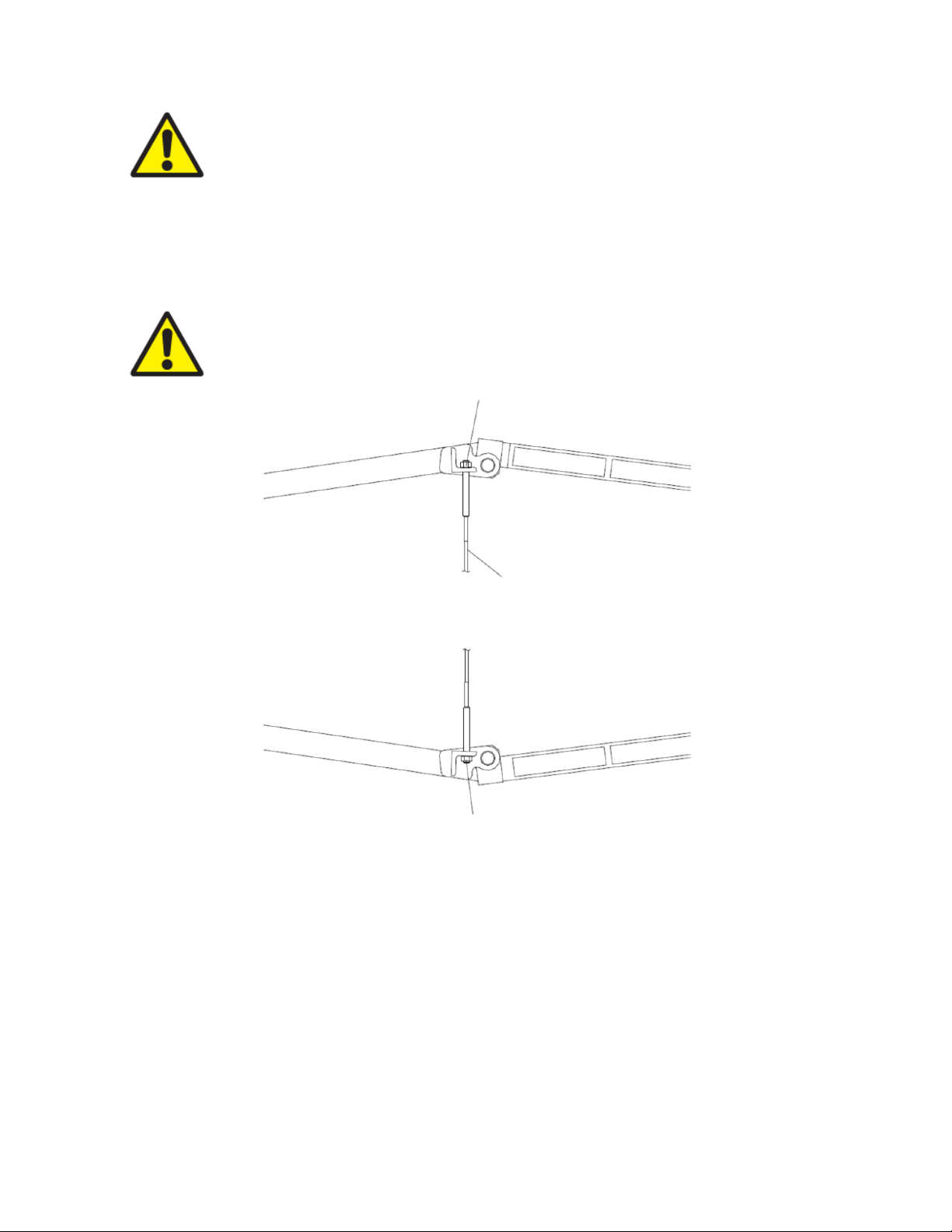
Warning:
(
by Energy Absorption Systems. Failure to use the correct equipment could lead
to improper system performance.
For proper system performance, only use Release Cables supplied
5) Assemble the Bottom Release Cable across the Arm Assemblies.
Verify that the frame is fully extended. Attach the Bottom Release Cable across Arm
Assemblies (See Figure 33). Torque the nuts to 34 N-m (-0, +3) [25ft-Ibf (-0, +2)]
making sure that roughly an equal amount of threads protrude from nuts on both ends
of cable. Lock cable in place using remaining fasteners as "jam" nuts.
Warning:
Until cables are assembled, the system may shift to one side.
TORQUE TO 34 N-m (-0, +3) [25 ft - Ib (-0, +2)]
RELEASE CABLE
TORQUE TO 34 N-m
-0, +3) [25 ft - Ib (-0, +2)]
Figure 33
www.energyabsorption.com Revision B June 2013
www.highwayguardrail.com 35 All rights in copyright reserved
Page 37

6) Assemble Cartridges
Remove one end of each alignment cable from the TMA and set aside to clear the top
side of each bay. Using a forklift and sling, place Cartridge B in position and secure it
using the flat washers, lock washers and nuts provided. Torque the nuts to 120±7 N-m
[90 ± 5 ft-lb] Repeat procedure for Cartridge A (See Figure 34).
7) Assemble the Top Release Cables across the Arm Assemblies
Assemble the Top Release Cable across the Arm Assemblies (See Figure 36). Torque
the nuts to 34 N-m [25 ft-lb], making sure that roughly an equal amount of threads
protrude from nuts on both ends of cable. Lock cable in place using remaining fasteners
as "jam" nuts.
Figure 34
www.energyabsorption.com Revision B June 2013
www.highwayguardrail.com 36 All rights in copyright reserved
Page 38

8) Reassemble and Adjust the Alignment Cables
There are four Top Cables (two for each bay). Reattach the Alignment Cables as shown
in Figure 35. Measure the diagonals of each bay and adjust the cables so that the
diagonal measurements in each bay are the same (A = B ±5 mm [3/16"], C = D ±5 mm
[3/16"]). Lock each cable in place using the second nut as a “jam nut”.
9) Replace Side-Guides
The Side-Guides must be inspected and replaced if damaged. The Side-Guides are
sacrificial and can be easily attached to their respective mounts. Side-Guides are
necessary for proper system alignment during an impact and must be in place to ensure
proper performance characteristics during system operation in an impact (See Figure
35).
Figure 35
www.energyabsorption.com Revision B June 2013
www.highwayguardrail.com 37 All rights in copyright reserved
Page 39

10) Assemble and Tension the Cartridge Support Cables
There are six Cartridge Support Cables. Pass the stud end of the cable through the
corresponding cartridge chain loop and attach as shown in Figure 36 using a die spring,
washer, and nuts.
To properly tension the Cartridge Support Cables, tighten the first nut on one cable until
all slack is removed then tighten it until the tensioning springs have been compressed
to 32 mm [1 1/4"] in height. Lock this nut in place with the second “jam” nut. Repeat this
procedure with the other cables.
11) Adjust the Height and Levelness of the System Frame
Verify that the System Frame is 305±25 mm [12”±1”] from the ground at the front and
rear of the system. It may be necessary to add shims to the Socket Hitches in order to
adjust the levelness of the Cartridge (See Figure 36a).
Figure 36a
Figure 36
± 2 mm [1 1/4" ± 1/16”]
www.energyabsorption.com Revision B June 2013
www.highwayguardrail.com 38 All rights in copyright reserved
Page 40

12) Verify Position of Hydraulic / Electrical Lines
Check the location of all the hydraulic and electrical lines to make sure they will not be
damaged during the folding and unfolding of the system.
13) Check System Lights for Proper Operation
Verify that all the turn / stop / tail / reverse lights are working properly. Replace any
bulbs that are out.
There are two light circuits on the TMA. Verify both circuits are operational.
Raise the system to folded position and verify secondary lights are working.
With the system unfolded, lights on the Impact Face will be on and lights on the Mid
Frame will be off.
With the system folded, the lights on the Mid Frame will be on and the lights on the
Impact Face will be off.
14) Final check
Check the tightness of all the fasteners. Check all steel cables to verify that they are
properly attached and tightened.
15) Ready to Use
The system is now ready for use.
www.energyabsorption.com Revision B June 2013
www.highwayguardrail.com 39 All rights in copyright reserved
Page 41

Troubleshooting Guide
Safety Notes – See Troubleshooting Decision Trees on Page 50.
1) Always wear eye protection when working on or around machinery or power tools, and
while working with hydraulics.
2) Do not attempt to control a hydraulic leak with your hand. High-pressure hydraulic fluid
can puncture the skin and cause severe injury or death. Use extreme caution when
working on hydraulic systems.
In general, consult Energy Absorption Systems Customer Service Department if problems
associated with operating or repairing the TMA should arise. This guide is meant to be an aide
for performing minor repairs, not a detailed repair Manual.
Note: For any problems not listed here, contact Energy Absorption Systems.
Test Equipment
The following is a recommended list of the test equipment required to troubleshoot DC
powered hydraulic systems.
1. Pressure Gage
A 34.5 MPa [5000 psi] pressure gage, preferably glycerin filled, is a valuable and
relatively inexpensive tool for checking fluid pressure in the various sections of the
circuit.
2. DC Test Light
A test light is a light bulb with one lead wired to an alligator clip and the other lead
connected to a metal probe. It is used to check for the presence of a voltage in the
electrical circuit. With the alligator clip grounded, the light glows when the probe comes
into contact with a hot electrical component.
3. Continuity Light
A continuity light is like a test light but contains its own battery. It is used for testing
electrical circuits when the components are not connected to a power source.
4. Volt Meter
A DC voltmeter can be used to troubleshoot voltage problems. Two common uses are:
1) Ground one probe while using the other to probe hot leads in search of the available
voltage at the point where the second probe is connected. 2) Measure a voltage drop in
a wire or component by connecting one probe to one end and the remaining probe to
the other end of the item in question.
5. Ohmmeter
Note:
disconnected from the system.
An ohm meter is used to measure resistance and is useful when working with solenoid
coils. On some coils the wire resistance is large enough that a DC test light might not
illuminate, falsely indicating an open circuit (infinite resistance). A successful coil test,
however, shall always show some non-infinite value of resistance.
6. Assorted Hoses, Pr essure Fittings
These can be used to connect and/or isolate certain parts of a hydraulic circuit for
diagnosing hydraulic problems.
If you suspect problems, do not operate the system. Diagnose and repair, or contact
Energy Absorption Systems Customer Service Department for input as to your specific
application.
All tests conducted with an ohmmeter must be done with the power source
www.energyabsorption.com Revision B June 2013
www.highwayguardrail.com 40 All rights in copyright reserved
Page 42

Hydraulic Fluid
1. Purpose
The main purpose of hydraulic fluid is to transfer power from the pump to the actuators.
Secondary tasks include reducing metal on metal friction and preventing the formation
of rust and sludge. These traits are achieved when the oil has a good lubricity
(slipperiness), and with additives that inhibit oxidation and the entrainment of air and
water in the oil, respectively. The viscosity (thickness) of the oil must be appropriate for
the operating temperature to minimize unwanted leakage and to lubricate the close
fitting parts in the system.
Additionally, the oil must be compatible with the seals used in the system. Finally, the
oil must be able to pour or flow at the lowest expected operating temperature so that it
can enter the reservoir and pump for use. For all of these reasons, automatic
transmission fluid (ATF, Dexron
fluid for the job in most climate conditions.
2. Selecting Fluids for Applications Outside ATF’S Temperature Range
When looking for fluids that can be used in place of ATF or for applications where the
operating temperature is outside the range of ATF, the following specs should be
discussed with your local oil distributor:
A. Fluid must be compatible with Buna-N sealing compounds.
B. The Pour Point must be below the lowest anticipated temperature that will be
encountered.
®
III) has been found to be the best readily available
C. It should contain Rust or Oxidation inhibitors as well as other detergent type
inhibitors.
D. The viscosity (SUS) shall lie between 80 and 375 in the operating range, with the
ideal viscosity near 200 SUS.
E. The viscosity index should be as high as possible. As an example, ATF has the
following specs as listed by most oil manufacturers:
[1] Viscosity (SUS)
37 deg. C [99 deg. F] 185 to 205
99 deg. C [210 deg. F] 45 to 55
Pour Point -44 deg. C [-47 deg. F] to
-37 deg. C [-35 deg. F]
Viscosity Index 145 to 165
Note: In an emergency, for cold weather applications, SAE 10 W non-detergent oil mixed by
volume with no more than 30% #1 fuel oil or kerosene can be used.
www.energyabsorption.com Revision B June 2013
www.highwayguardrail.com 41 All rights in copyright reserved
Page 43

Hydraulic System
Finding & Solving Problems
Caution: Repair of hydraulic components shall only be performed by fully qualified
individuals or hydraulic shops. In most cases, contact Energy Absorption Systems
Customer Service Department for advice on repair or replacement of TMA parts. All
replacement components must be approved for use or provided by Energy Absorption
Systems to guarantee quality and correctness.
Hydraulic system failures can occur in several ways: A gradual or sudden loss of
pressure or flow, a loss of power at the pump, or other difficulties. Any of the system’s
components could be the cause. Start with the checklist below that most applies to the
symptom at hand.
Note: Avoid the use of Teflon
cause failures in the hydraulic system.
1. Motor does not Start
Improper ground. Check ground conditions.
Improper or low voltage supply. Check voltage supply from truck battery and at pump.
Electrical system inoperative: Verify that cable from battery is correctly attached.
Failed motor solenoid: Replace, taking note of correct wire locations for reassembly.
®
tape on hydraulic fittings as it can easily jam valves and
2. System Operates Rough or Erratic
Insufficient or no oil system, pump losing prime: Fill system, check for leaks.
Ground fault: Check for loose wire leads, verify that pump is securely mounted to TMA
frame and that the truck lighting plug is correctly attached. Ensure ground wire from
pump is directly routed to the truck battery.
Wrong oil in system (should be ATF Dexron
®
III): Change Oil.
Clogged or dirty cylinder check valve: Remove the load on cylinders, disassemble
cylinder check valve and clean (See section on Cylinder Check Valves).
Oil line is restricted, dirty, or collapsed: Clean or replace oil line.
Dirty pump: Clean exterior and check for contaminated oil. If necessary, drain, flush,
and refill system with ATF Dexron
®
III.
Worn components (valves, cylinders, etc.): Check for cause of wear. Replace worn parts
with correct components.
Leakage: Check all components, verify tightness of fittings, and inspect hoses for wear
while system is idle. Replace damaged hoses or fittings.
Excessive loading (especially any features not originally installed by Energy Absorption
Systems): Remove excessive load.
www.energyabsorption.com Revision B June 2013
www.highwayguardrail.com 42 All rights in copyright reserved
Page 44

3. System Operates Slowly or Cavitates
Low voltage: Verify voltages with DC voltmeter and check truck charging system.
Oil viscosity too high or cold oil: Allow oil to warm up before operating or replace with oil
as necessary.
Air in system: Check for leaks and tighten as necessary. Cycle the system several times
to relieve air from system.
Oil leaks: Tighten fittings, replace seals or damaged lines.
Worn components (valves, cylinders, etc.): Check for cause of wear. Replace worn
parts with correct components.
Restriction in lines or cylinder check valves: Remove the load on cylinders, clean lines
or valves, replace hoses if necessary.
4. System Operates too Fast
Internal fixed flow controls reversed: Contact Energy Absorption Systems
5. Pump Overheats
Low voltage at pump: Check battery and wiring
Incorrect, low volume, or dirty oil: Add or change oil as necessary
Excessive internal leakage (pump): Replace the pump (contact Energy Absorption
Systems).
Restriction in lines or cylinder check valves: Remove the load on cylinders, clean lines
or valves, replace hoses if necessary.
Insufficient heat radiation: Clean dirt and mud from reservoir and components.
6. Noisy Pump
Low oil level, incorrect or foamy oil: Replace or add oil as necessary.
Suction line or inlet screen plugged: Consult Energy Absorption Systems.
Worn or damaged pump: Replace the pump (contact Energy Absorption Systems).
7. Load Drops When System is Locked
Leaking cylinder seals or fittings: Remove the load on cylinders, inspect for damaged
hoses or fittings, tighten fittings or replace hoses if necessary.
Faulty counterbalance valve: Remove the load on cylinders. Clean or replace the
appropriate counterbalance valve components.
8. Leaky Cylinder(s)
Seals worn or damaged: Replace the cylinder.
Rod damaged: Replace the cylinder.
www.energyabsorption.com Revision B June 2013
www.highwayguardrail.com 43 All rights in copyright reserved
Page 45

Pressure Relief Valve
1. Purpose
A. Limit the maximum pressure in the hydraulic system to a safe level.
B. Keep the motor amperage (and battery drain) at a minimum when the c ylinders dead
head (reach full stroke).
2. Adjusting Relief Valve (on the pump)
Note: In general, do not adjust the relief valve. It is set to the correct operating pressure at
the factory.
A. Symptoms of incorrect pressure relief adjustment.
1) Relief pressure too high
a. Battery current draw is excessive
b. Motor RPM is slow
2) Relief pressure too low.
a. Motor RPM is fast
b. System will not fold (cylinders will not extend).
c. Excessive turbulence in reservoir.
Note: On applications where a hydraulic component is being replaced, contact Energy
Absorption Systems Customer Service Department to purchase replacement parts.
Warning: Do not exceed pressure rating for hydraulic system components! System
pressure is set to 2400 psi at the factory.
Counterbalance Valve
1. Purpose
The counterbalance valve allows free flow of hydraulic oil into and out of the cylinders but
blocks the flow when there is no pump pressure. The counterbalance valve locks the
system when the pump is not running.
Warning: When the system is stopped at an intermediate angle, there will be
pressure on the oil in the hoses between the counterbalance valve and cylinders!
This pressure is supporting the load of the folding bay! ALWAYS make sure the TMA
is completely folded or completely unfolded before loosening a hose fitting or
servicing any check valve! This will minimize the chance of injury from an
uncontrolled falling load or spray of high-pressure oil. Never stand underneath the
TMA when performing any sort of service or checking any component of the system.
www.energyabsorption.com Revision B June 2013
www.highwayguardrail.com 44 All rights in copyright reserved
Page 46

2. Repairing Counterbalance Valve
A. Symptoms
If the TMA exhibits a slow drifting of the folding bay when the pump is not running, one
of the following may be true:
1) The counterbalance valve has become blocked by foreign debris in the oil line.
2) The piston ring seals inside the cylinders have been compromised.
B. Repair procedure
1) Blocked Cartridge
a. Again, make sure the system is completely folded or completely unfolded.
b. Remove the Cartridge from the valve body, being cautious of oil spray from
residual pressure in the system.
c. Clean the Cartridge using compressed air, making sure to direct the air away
from anyone’s face. Avoid breathing the oil mist that this process may create.
d. Reinsert the Cartridge as they were before disassembly.
2) Piston ring seal
a. Refer to the following section on Hydraulic Cylinders.
Note: If the counterbalance valve has failed in some other way, do not attempt to repair
it. Replace it with a new valve by contacting Energy Absorption Systems Customer
Service Department.
www.energyabsorption.com Revision B June 2013
www.highwayguardrail.com 45 All rights in copyright reserved
Page 47

Hydraulic Cylinders
Caution: Never allow anyone underneath the moving portion of the SS180 TMA
out all loads and disconnect electrical contact prior to performing any service on
hydraulic equipment.
®
. Block
1. Troubleshooting
If you suspect problems with the hydraulic cylinders on the TMA, you may need to remove
the cylinders from the TMA for repair or replacement. The cylinders can only be removed
when the TMA is completely folded. Double check all electrical contacts between the TMA
and support vehicle have been disconnected prior to performing any work on the hydraulic
system.
A cracked, bent, or leaky cylinder may need repair but will almost always be replaced to
ensure reliable performance.
2. Cylinder Replacement
A. Completely fold the TMA.
B. Unplug all electrical connections between the TMA and the support vehicle.
C. See Hydraulic Cylinder Assembly drawing 610306. Loosen (but do not disconnect) the
“Follower Link Pivot” and the “Push Link Pivot” where they are bolted to the “Weldment,
Front Intermediate Frame” and the “Weldment, Rear Intermediate Frame”, respectively.
D. At the top end of the cylinder rod, loosen the set screw and push out the short 1”
diameter pin, making note of the alignment and location of all linkage components for
later reassembly.
E. Disconnect the hoses leading into the cylinder at two convenient locations and place
temporary caps on the hoses or cylinder ports to prevent spillage or contamination.
F. At the bottom end of the Cylinder b ody, remove the Cotter Pin from the Clevis Pin and
push out the long 1” diameter pin, making note of the alignment and location of all
components for later reassembly.
G. The cylinder should now be free. Reinstall a new cylinder in the reverse order of these
removal steps, making sure to properly align and (where necessary) tighten all
components. Use blue thread locker (medium strength) on all fasteners.
Note: See the section on Hydraulic System Priming. You will likely need to prime
the system if you are installing a new or “dry” cylinder.
3. Repairing Cylinders
Replace any faulty or damaged cylinders with a new cylinder.
www.energyabsorption.com Revision B June 2013
www.highwayguardrail.com 46 All rights in copyright reserved
Page 48

Hydraulic System Priming
SS180 TMA® hydraulic systems come direct from the factory primed and ready to operate.
Priming should only be necessary after changing the oil or if you have recently repaired a leak.
1. Priming Process
Systems that have been disassembled for repair require priming for proper performance.
The hydraulic system is said to be primed when all hoses and cylinders are full of oil and
the air has been expelled. The reservoir shall be full of oil (oil just visible at the filler port)
when the TMA is UNFOLDED. Prime the pump as follows:
A. Detach the long hoses where they connect to the cylinder. Note which hoses connect to
the top and bottom of the cylinder.
B. Jog and pump by briefly depressing the “FOLD” button until clean oil flows from two of
the hoses.
C. Repeat this process for the other two hoses by briefly depressing the “UNFOLD” button.
D. Replace and retighten all four hoses.
Caution: Do not completely fold or unfold the TMA until it has been jogged a few times
to work out any air in the system. Add oil at the filler port any time that the pump begins
to cavitate.
E. Jog the system a few times by depressing “FOLD” or “UNFOLD” (depending on the
current state of the TMA).
2. Check for These Problems When a System Fails to Prime
Correct pump mounting, with the motor on top and reservoir at the bottom. All SS180
A solid plug in the reservoir filler port instead of a vent plug (See Reservoir section).
®
TMA
’s shall have vertically mounted pumps. Mounting a pump in some other orientation
would prevent the suction line from picking up oil, causing cavitation.
Note: Vertical mount pumps have a label stating such designation.
Reservoir
Note: Do not use a solid plug or fill cap without a filter/breather element, or damage will
be caused to the pump and/or reservoir.
1 Use Recommended Fluid:
Fill reservoir with Dexron® III only (See Hydraulic Fluid section).
2 Proper Filling:
A. With the TMA UNFOLDED (cylinders fully retracted), fill the reservoir so that oil can just
be seen in the filler port.
B. Operate the unit several times starting with short cylinder strokes, increasing the length
of each successive stroke.
C. Recheck oil level often and add as necessary to keep the pump from picking up air.
D. Reinstall the filter/breather plug provided.
www.energyabsorption.com Revision B June 2013
www.highwayguardrail.com 47 All rights in copyright reserved
Page 49

3 Reservoir Problems
A. Clear oil flowing out of the filler port usually means the reservoir was completely filled
before the cylinders were fully collapsed (TMA unfolded).
B. Foamy oil flowing out of the filler port points to one of the following:
1) Air present in the system; the response is usually spongy or the cylinders may move
with a jerking motion.
2) There is no drop tube or “down spout” on the return line so that the oil is not
returning to the bottom of the reservoir.
C. Water in the oil:
Water can enter the reservoir through the filler port if the unit is left outdoors or washed
with a high-pressure washer. Protect the unit, whenever possible, and change the oil if
you suspect contamination. In cold weather the water could freeze, preventing the
pump from working until the ice melts.
Warning: Remove all rings, watches, jewelry, etc. prior to doing any electrical work!
Electrical Problems
1 Low Voltage
Operating DC (direct current) power units efficiently requires proper voltage. Any attempt to
operate below the minimum required voltage could cause system failure.
A. Signs that point to low voltage are:
1) Motor won’t run because solenoid won’t shift.
2) Motor running at reduced speed.
B. Minimu m voltage requirements:
1) Between the motor stud and ground: 9.0 volts at maximum load.
C. Causes for low voltages are:
1) Improper ground. Check grounds.
2) Battery capacity too small.
3) Cable ends not electrically secure to battery cable.
4) Battery cable size too small for load and length of run. Copper #4 automotive is the
recommended minimum size battery cable. Larger copper battery cable (#2, #1, #0,
or #00) may be required for cable lengths over 25 feet to keep performance from
deteriorating.
5) The pump ground is established through the battery ground cable. Clean any dirt or
rust from cable to achieve proper ground.
6) Burnt contacts on motor solenoid.
D. Check for low voltage as follows (requires a voltmeter):
1) On alternator equipped vehicles, verify that the battery voltage is approximately
13.5 volts with no electrical accessories operating and the engine running.
2) Operate the TMA while an assistant uses the voltmeter to probe each connection,
cable end, and cable from the battery all the way back to the motor stud. Note the
voltage losses. Make necessary repairs. Increase the voltage above the minimum
as required.
Note: Check the ground connections as well: remove any paint, rust, and dirt that may
be acting as insulators.
www.energyabsorption.com Revision B June 2013
www.highwayguardrail.com 48 All rights in copyright reserved
Page 50

2 DC Motors
Before concluding that the hydraulic pump is malfunctioning:
Verify that all connections are secure and that the problem does not lie somewhere
else.
Check ground.
Check brushes for wear, and replace if necessary.
Note: A motor that does not turn in freezing weather could be caused by frozen
water in the oil.
If it has been verified that the pump is defective; contact Energy Absorption Systems
Customer Service Department for input as to your specific application (See Page 3).
3 Electrical Switches
A. If you suspect that the switch is defective, use one of these three methods to test the
operation of the switch:
1) First check grounds.
2) Use continuity light to test the switch (See Test Equipment section).
3) Use a circuit test light to test the switch (See Test Equipment section).
B. Motor solenoid switches:
The solenoid switches found on the hydraulic pump are four post style solenoid. They
shall be constructed and wired such that:
1) The large posts with the connecting bar must be attached to the cable from the
battery.
2) The same post (shared hot lead) provides power to the control circuit.
3) The remaining large posts attach to the motor wires.
4) The small post on each solenoid connects to the control circuit on the side and the
other small post connects to the ground. This circuit activates the solenoid (and
hence the pump) when energized.
4 Electrical Polarity
The pump motor and all controls have a negative ground.
5 Electrical Shorts or Open Circuits
A. Shorts occur when wires with power come in contact with a ground. A short will cause a
fuse to blow or a wire to burn. Look for pinched or cut wires.
B. An open circuit is simply a break which prohibits current flow. Look for pinched or cut
wires.
www.energyabsorption.com Revision B June 2013
www.highwayguardrail.com 49 All rights in copyright reserved
Page 51

Troubleshooting Decision Trees
www.energyabsorption.com Revision B June 2013
www.highwayguardrail.com 50 All rights in copyright reserved
Page 52

www.energyabsorption.com Revision B June 2013
www.highwayguardrail.com 51 All rights in copyright reserved
Page 53

www.energyabsorption.com Revision B June 2013
www.highwayguardrail.com 52 All rights in copyright reserved
Page 54
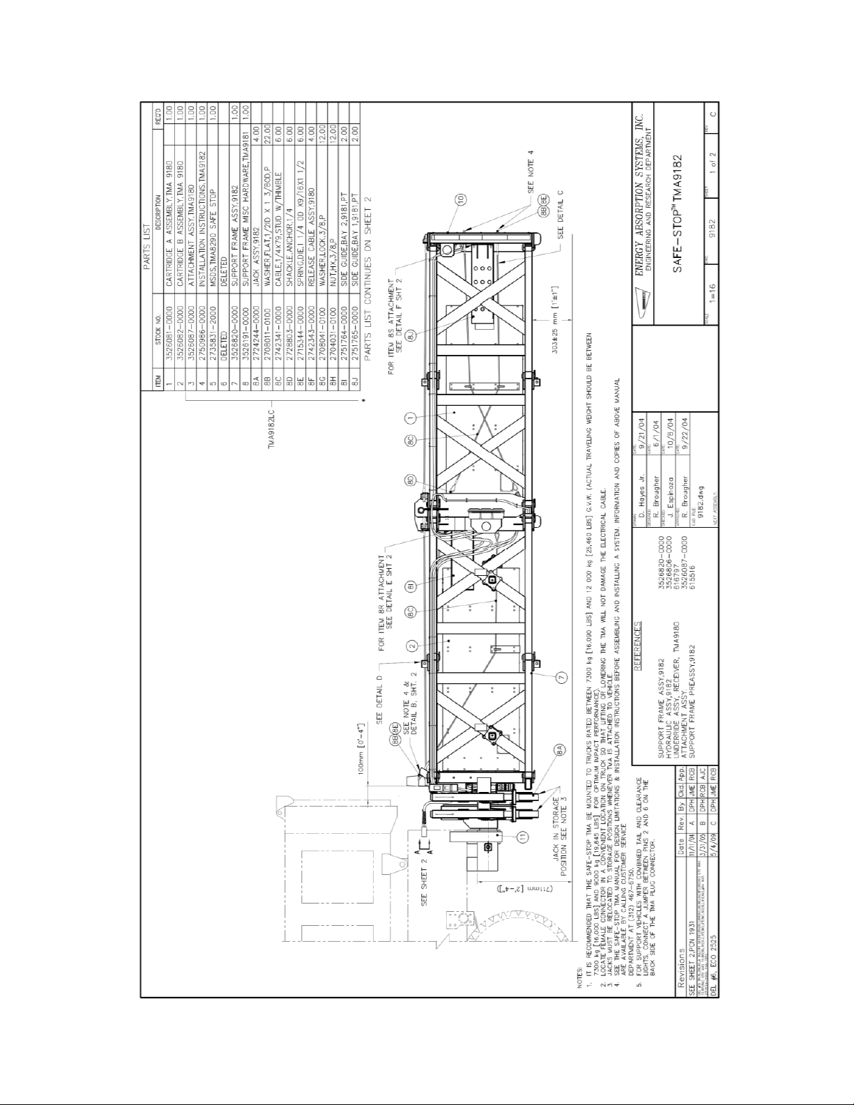
®
9182
DWG 9182 Sheet 1 of 2
www.energyabsorption.com Revision B June 2013
www.highwayguardrail.com 53 All rights in copyright reserved
SS180 TMA
Page 55
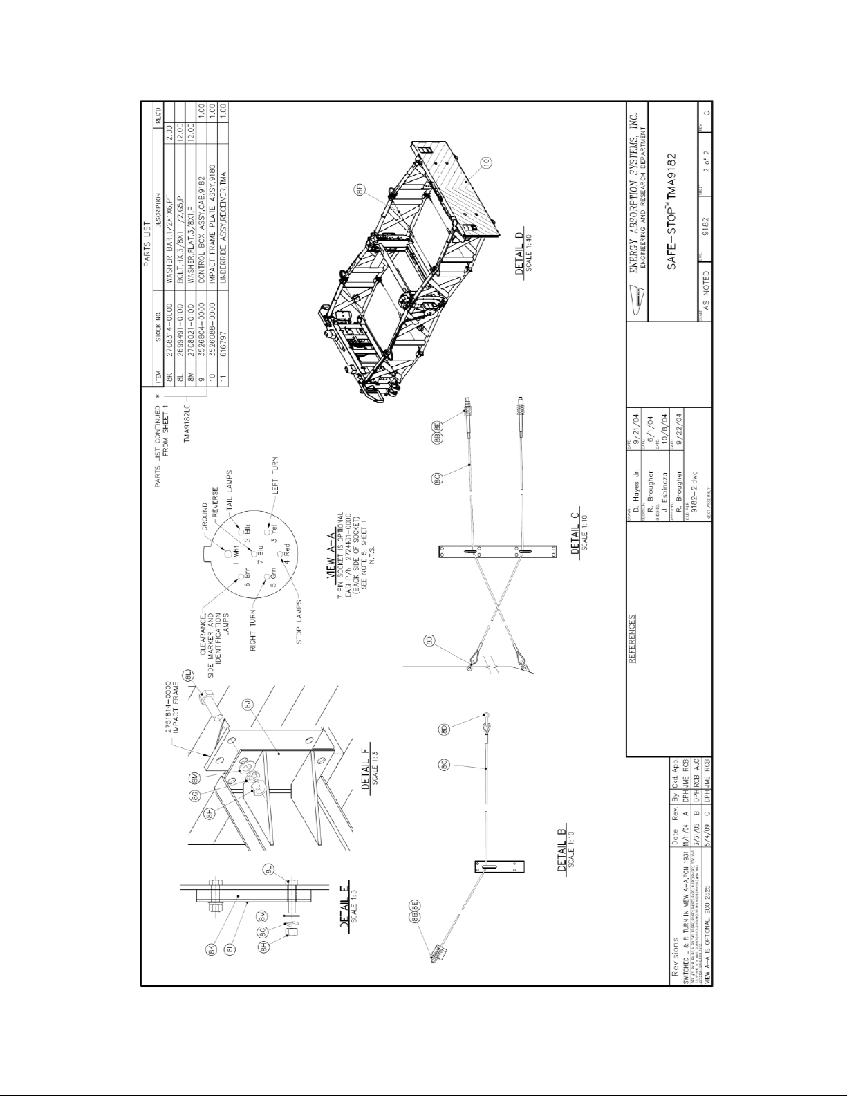
DWG 9182 Sheet 2 of 2
www.energyabsorption.com Revision B June 2013
www.highwayguardrail.com 54 All rights in copyright reserved
Page 56

DWG 3526820-0000
Support Frame Assembly, 9182
www.energyabsorption.com Revision B June 2013
www.highwayguardrail.com 55 All rights in copyright reserved
Page 57

DWG 3526806 Sheet 1 of 2
Hydraulic Assembly, 9182
www.energyabsorption.com Revision B June 2013
www.highwayguardrail.com 56 All rights in copyright reserved
Page 58
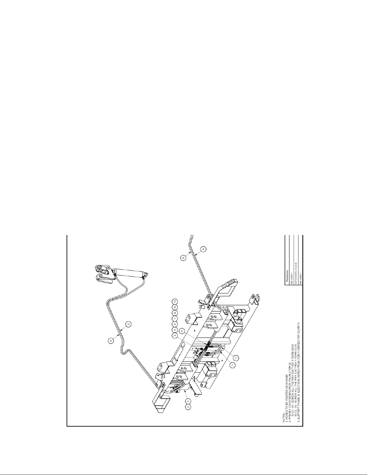
DWG 3526806 Sheet 2 of 2
www.energyabsorption.com Revision B June 2013
www.highwayguardrail.com 57 All rights in copyright reserved
Page 59

DWG 3526807
Hydraulic Pump Assembly, 9182
www.energyabsorption.com Revision B June 2013
www.highwayguardrail.com 58 All rights in copyright reserved
Page 60
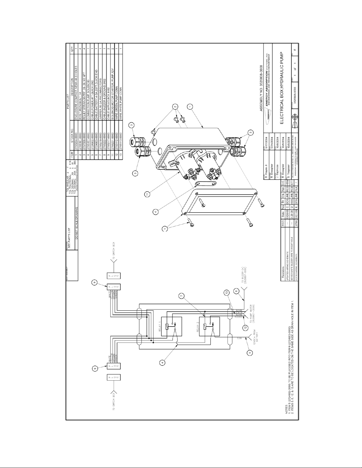
DWG 3526808
Electrical Box Hydraulic Pump
www.energyabsorption.com Revision B June 2013
www.highwayguardrail.com 59 All rights in copyright reserved
Page 61
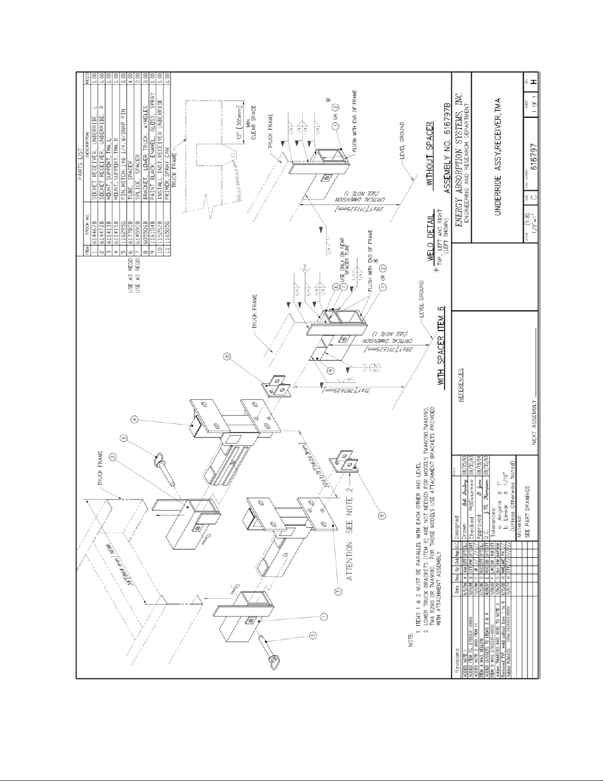
DWG 616797
Underride Assembly Receiver, TMA
www.energyabsorption.com Revision B June 2013
www.highwayguardrail.com 60 All rights in copyright reserved
Page 62

DWG 604382
Attachment Assembly, 9180
www.energyabsorption.com Revision B June 2013
www.highwayguardrail.com 61 All rights in copyright reserved
Page 63

DWG 352682A Sheet 1 of 3
Support Frame Preassembly, 9182, 24V
www.energyabsorption.com Revision B June 2013
www.highwayguardrail.com 62 All rights in copyright reserved
Page 64
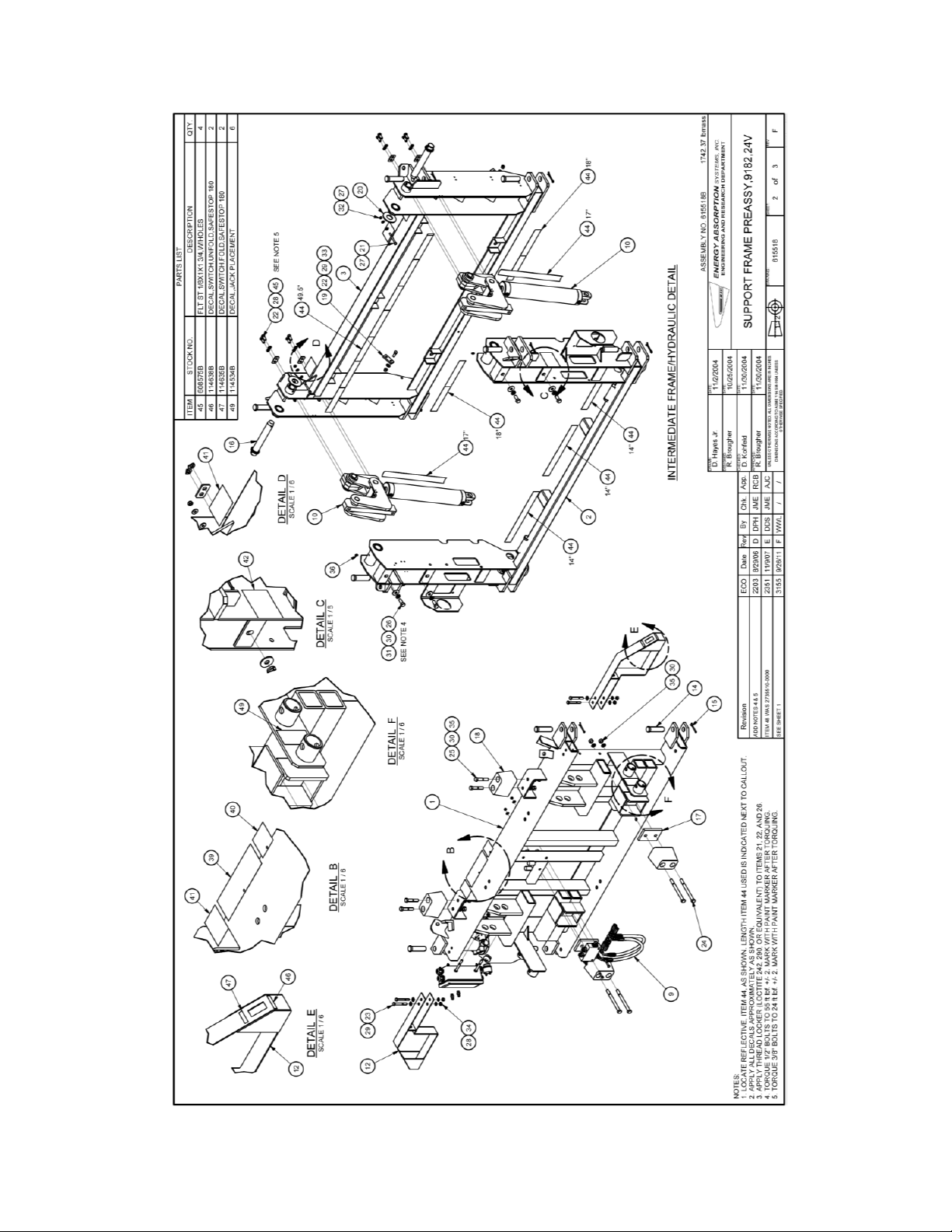
DWG 352682A Sheet 2 of 3
www.energyabsorption.com Revision B June 2013
www.highwayguardrail.com 63 All rights in copyright reserved
Page 65
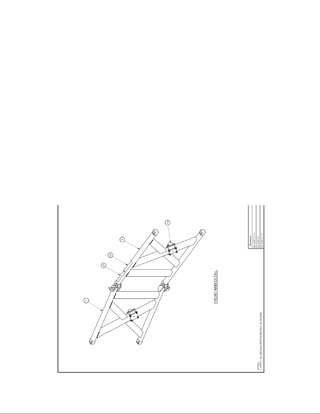
DWG 352682A Sheet 3 of 3
www.energyabsorption.com Revision B June 2013
www.highwayguardrail.com 64 All rights in copyright reserved
Page 66

DWG 3526800 Sheet 1 of 3
Lighting/Wiring Assembly, 9182
www.energyabsorption.com Revision B June 2013
www.highwayguardrail.com 65 All rights in copyright reserved
Page 67

DWG 3526800 Sheet 2 of 3
www.energyabsorption.com Revision B June 2013
www.highwayguardrail.com 66 All rights in copyright reserved
Page 68

DWG 3526800 Sheet 3 of 3
www.energyabsorption.com Revision B June 2013
www.highwayguardrail.com 67 All rights in copyright reserved
Page 69

DWG 3526820-0000
Support Frame Assembly, 8291
www.energyabsorption.com Revision B June 2013
www.highwayguardrail.com 68 All rights in copyright reserved
Page 70

DWG 610306
Hydraulic Cylinder Assembly, 9182
www.energyabsorption.com Revision B June 2013
www.highwayguardrail.com 69 All rights in copyright reserved
Page 71

Notes:
www.energyabsorption.com Revision B June 2013
www.highwayguardrail.com 70 All rights in copyright reserved
Page 72

2525 Stemmons Freeway
Dallas, Texas 75207
888-323-6374 (USA only)
214-589-8140 (Outside USA)
www .energyabsorption.com
www.highwayguardrail.com
 Loading...