

Page 1

ENERGY ABSORPTION SYSTEMS
SRT-350
Guardrail End
Treatment
Assembly Manual
Part No. 620295B Revised March 2010
®
6 POST
Page 2

Page 3
2
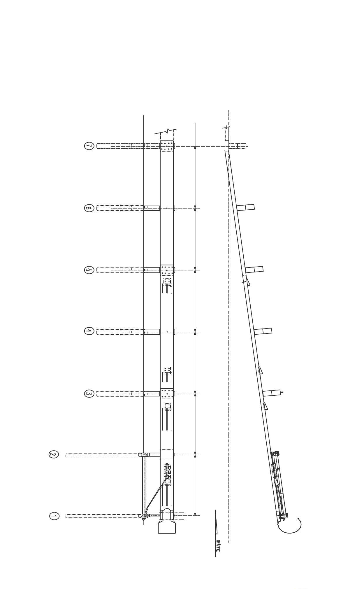
SRTTM/ HBA
TM
6-POST SYSTEM
FOR SPECIFIC DETAILS, REFER TO THE
STATE STANDARD DRAWING
"3-'6
"3-'6
"3-'6
"3-'6
"3-'6
"3-'6
Page 4

SRT
TM
/ HBA
TM
6-POST SYSTEM
BILL OF MATERIAL ENGLISH (METRIC)
(FOR QUANTITIES, SEE STATES OPTION(S))
PC
3G 12/12"/ BACKUP (2.67/0.305) GUARDRAIL
9G 12/12.5'/6'3"/S (2.67/3.81/1.905/S) GUARDRAIL
30G 12/12.5'/6'3"/S (2.67/3.81/1.905/S) SRT-1 ANC GUARDRAIL
39G 12/12.5'/6'3"/S (2.67/3.81/1.905/S) SR T-2 GUARDRAIL
700A CABLE ANCHOR BRACKET
907G 12 (2.67)/BUFFER/ROLLED (TERMINAL)
3000G CABLE ASSEMBLY 3/4" x 6'6" (19 x 1981)
3300G 5/8" (16) WASHER
3340G 5/8" (16) HGR NUT
3360G 5/8" DIA. x 1 1/4" (16 DIA x 35) HGR SPLICE BOLT
3380G 5/8" DIA. x 1 1/2" (16 DIA. x 38) HEX HEAD BOLT
3400G 5/8" DIA x 2" (16 DIA. x 50) POST BOLT
3580G 5/8" DIA x 18" (16 DIA x 460) HGR POST BOLT
3701G 3/4" (19) WASHER
3704G 3/4" (19) HEX NUT
3718G 3/4" DIA X 3 "(19 DIA. x 75) HIGH STRENGTH HEX HEAD
3900G 1" (25) WASHER
3910G 1" (25) HEX NUT
4063B WOOD POST 6" x 8" x 6'0" (150 x 200 X 1830)
4075B WOOD BLOCK 6" x 8" x 14" (150 x 200 x 360) DR
4254G 3/8" (10) WASHER
4258G 3/8" (10) LOCKWASHER
4261G 3/8" x 1 1/2" (10 DIA. x 38) HEX HEAD BOLT (GR 5)
4699G 3/4" (19) LOCKWASHER
6321G 3/8" DIA. X 2 " (10 DIA x 50) HEX HEAD BOLT (GR 5)
6405G 3/8" (10) HEX NUT
9960G SLOT GUARD
9961G 3/8" x
33876A HBA POST 1 TOP (W6 x 8.5)
33877A HBA POST 2 TOP (W6 x 8.5)
33878A HBA POST 1 & 2 BOT (TS 6 x 4)
33879G ANGLE STRUT 2" X 2" X 3/8" (50 x 50 x 10)
33880G 1" x 6" x 8" (25 x 150 x 200) BEARING PLATE
33881G CABLE WEB PL 4" x 1/4" x 5 3/4" (100 x 6 x 146)
QTY DESCRIPTION
1
1
1
1
1
1
1
14
58
44
8
2
4
10
4
4
BOLT
1
1
4
4
5
4
1
4
4
5
4
1
1
1
2
2
1
1
3" x 4" (10 x 75 x 100) PLATE WASHER
DELINEATION OPTIONS
6665B 1 STRIPED (YELLOW/BLACK) REFLECTOR 16" x 16"
(400 x 400)
3
Page 5

4
INSTALLING THE
SRT
TM
/ HBATM6-POST SYSTEM
MATERIALS
As packaged, the SRTTM/HBATMPost System includes all materials needed
for the installation.
Note that concrete footings or foundations are not required.
TOOLS REQUIRED
Tools required are those ordinarily used to install standard highway
guardrail (HGR). They include 9/16", 15/16", 1-1/4" and 1-1/2" sockets
and wrenches and such other equipment as augers and post pounders
commonly used in driving posts.
SITE PREPARATION
Site grading is usually necessary for the proper placement of the HBA
TM
posts and the Controlled Release Terminal (CRT) posts. It is suggested
that this grading be completed before the start of the installation of the
SRT
TM
/HBATM.
INSTALLATION
Be sure adequate time is allowed for "same day" complete installation.
If special field conditions are encountered when installing t he
SRT
TM
/HBATMPost System, contact Trinity Engineering @ 1-800-644-7976
to review the conditions.
POST LAYOUT
The SRTTM/HBATMPost System is a 37'6" (11.43 m) that utilizes a straight
flare. Start at the end (post location 7) of the guardrail run and measure
along the flared system a distance of 37'6" (11.43 m). At this point,
measure an offset of 4'0" (1.21 m) perpendicular to the road. This
establishes the face location of post no. 1. A straight line between post
no. 1 and face of the blockout of post no. 7 establishes the location of
either the face of the post or the face of the blockout for each of the
posts. All posts are spaced at 6'3" (1905 mm) on center.
Trinity Highway Products drawings for the SRT should be used with
these instructions. The states standard drawings for this system need
to be reviewed for details that will be specific to that state.
The SRT™/HBA™ Post System has a straight flare; the earlier versions of
the SRT-350™ used a parabolic (curved) flare. At posts one and two,
HBA™ posts are used in place of the soil tubes and wood posts. The
same equipment and expertise is required for both systems. Anyone with
experience installing the SRT-350™ should have no difficulty installing the
SRT™/HBA™ Post System.
Page 6
5
INSTALLING THE CRT POSTS
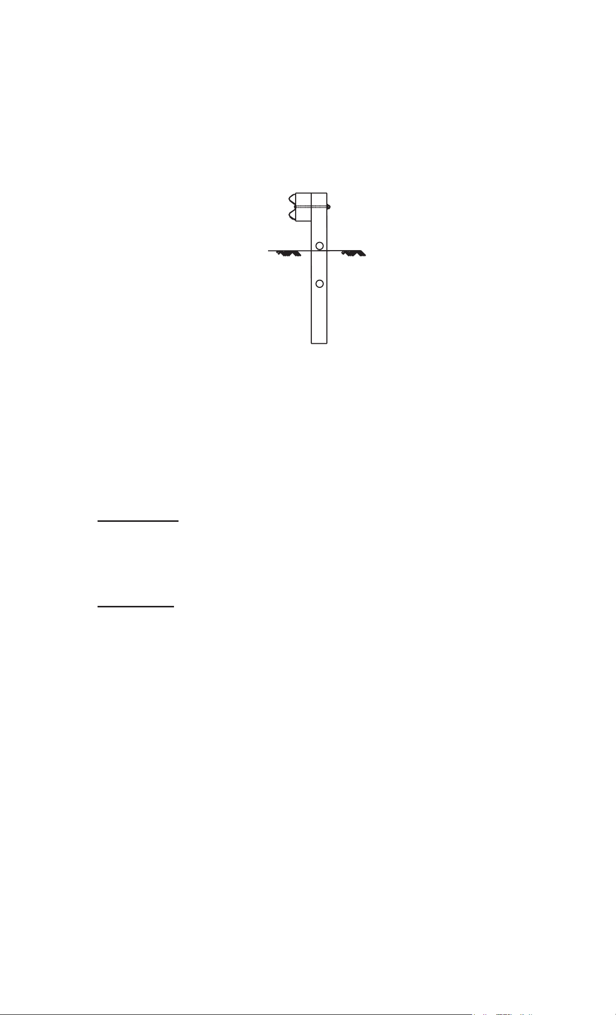
Install the wood posts at locations 6 thru 3. These posts (PC-4063B)
may be driven. They may also be installed by drilling holes
approximately 44" (1120 mm) deep. Insert the 6'0" (1830 mm) wood
post into these holes and backfill. Note that in either case, the bottom
of the upper 3 1/2" (90 mm) hole in the post is approximately at
finished grade. Posts 3 thru 7 are spaced at 6'3"
(1905 mm) intervals.
See Figure 1.
FIGURE 1
INSTALLING HBATMBOTTOM POSTS
There are two methods for the installing the HBATMbottom posts at
locations 1 and 2. The posts should be oriented so that the larger hole
(13/16" (21 mm)) is placed downstream (away from the end of the
system).
METHOD A Drive the HBA Bottom Posts (PC-33878A) with an
approved driving head to the appropriate depths, approximately
72"(1830 mm). The optimum depth will have the bottom of the
13/16" (21 mm) holes in the ears even with the finished grade.
METHOD B
mm) deep and Install the HBA Bottom Posts to the appropriate depth.
The optimum depth will have the bottom of the 13/16" (21 mm) holes
in the ears even with the finished grade.
Drill a 12" (300 mm) pilot hole approximately 72" (1830
If METHOD B is used, material should be placed in 6" (150 mm) lifts
and compacted with pneumatic equipment to optimum compaction.
INSTALLING HBATMPOSTS
WHEN ENCOUNTERING ROCK
If rock is encountered when installing the HBA posts, use the
following procedures, unless there is a more restrictive state
specification.
If rock is encountered and 20" (510 mm) or less depth is required to
complete the installation of the bottom HBA post, drill a 12"-16" (300
mm - 400 mm) diameter hole in the rock. The hole should be drilled
2" (50 mm) deeper than required embedment depth. Place in the
bottom 2 inches (50 mm) of the hole for drainage granular material
Page 7
6
or small pieces of the drilled rock. Backfill and compact the hole after
installing the HBA
hole may be used for the backfill.
If rock is encountered and more than 20" (510 mm) depth is required to
install the bottom HBA post, drill a 12"-16" (300 mm-400 mm) diameter
hole 22" inches (560 mm) deep into the rock. Install the HBA post in the
hole. Cut off the embedded portion so the guardrail will be installed at
the proper mounting height. Place in the bottom 2 inches (50 mm) of
the hole for drainage granular material or small pieces of the drilled rock.
Backfill and compact the hole after installing the HBA post. If
compactable, the material removed from the hole may be used for the
backfill.
If the finished grade is paved around terminal posts l and 2, a 3" deep
recess around each post needs to be provided to allow for the top post
to rotate when impacted. (See Figures 6 and 7). The recesses should
not be filled with compacted asphalt or concrete.
TM
post. If compactable, the material removed from the
INSTALLING HBATMTOP POSTS
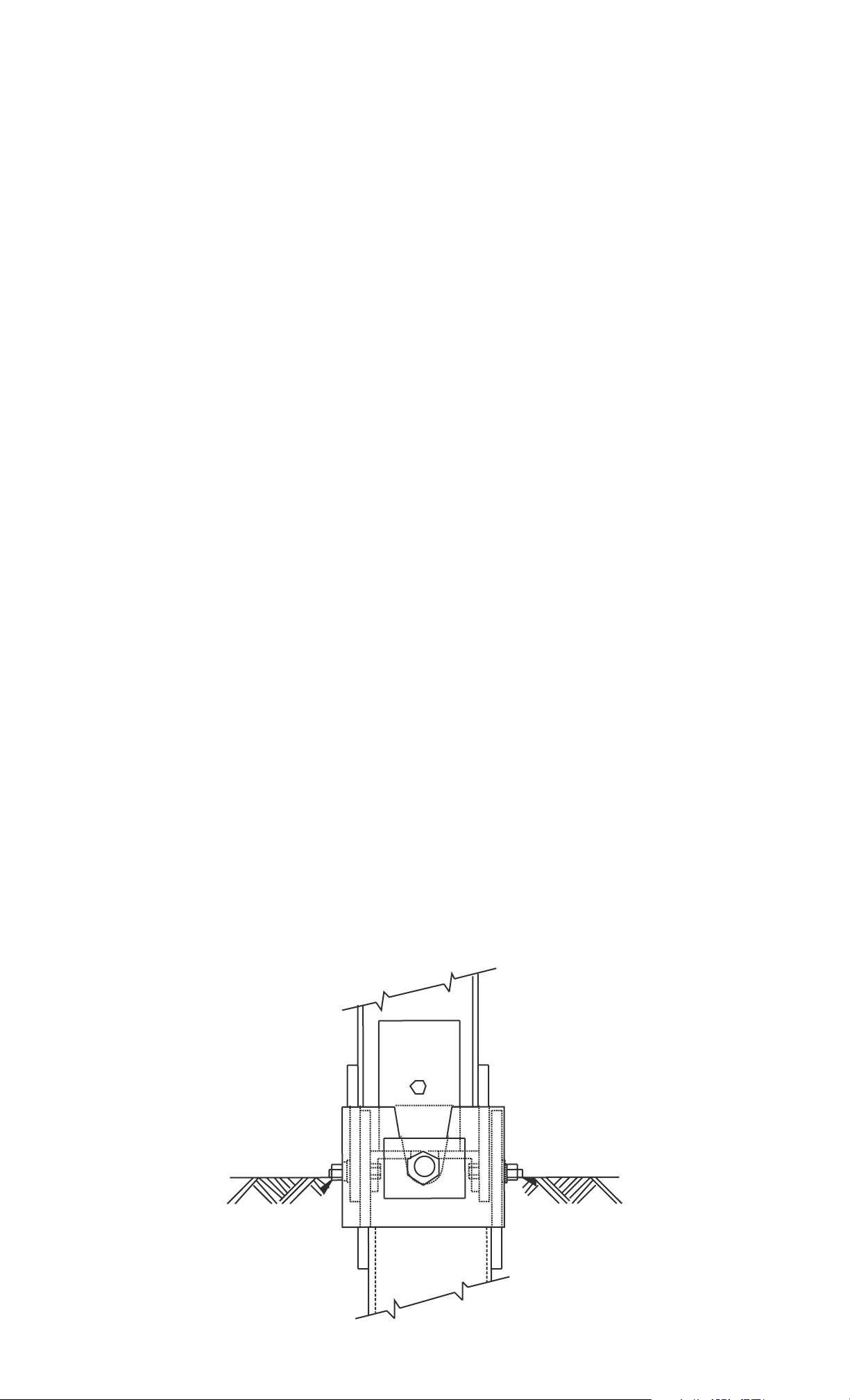
Once the bottom posts are installed, the upper post can be installed.
The post plates (ears) can be installed on either side of the bottom post
plates (ears). At post location No. 1, install the upper post (PC-33876A)
by aligning the holes of the post plates (ears) of the upper and lower
posts. In the 7/16" (11 mm) holes, install a 3/8" (10 mm) diameter x 2"
(50 mm) hex head bolt with a 3/8" (10 mm) washer, 3/8" (10 mm) lock
washer under the 3/8" (10 mm) hex nut. See Figure 2.
The bolts should be installed so the head of the bolt is on the inside of
the post plates (ears) and the washer and lock washer under the nut are
on the outside of the post plates.
There is no torque requirement for these bolts . They should be
tightened to a snug position.
FIGURE 2
Page 8
7
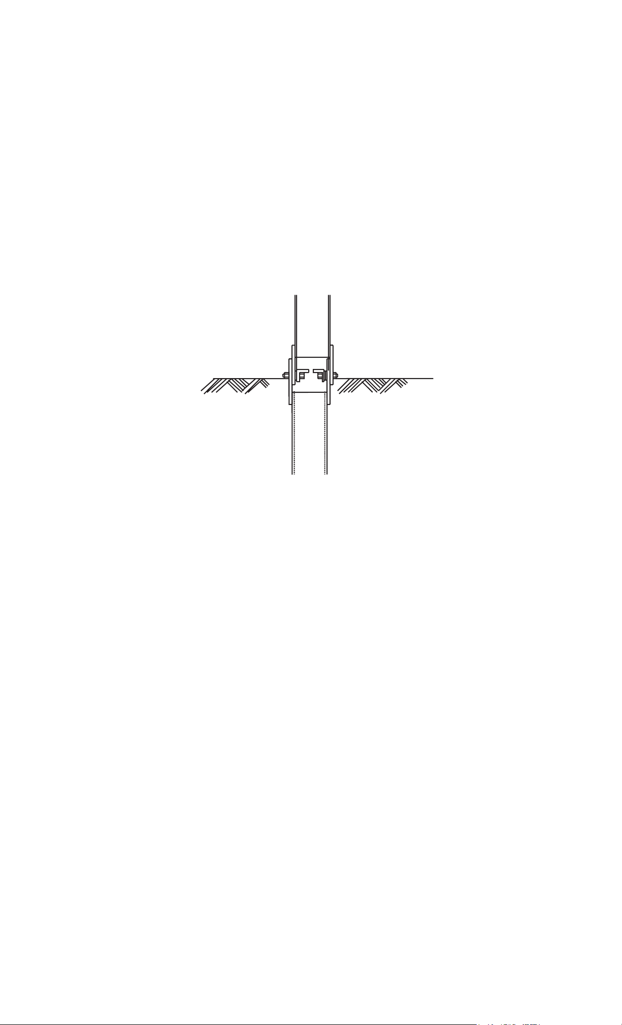
At Post Location No. 2, install the upper post (PC-33877A) by aligning the
holes of the post plates (ears) on the upper and lower posts. In the 7/16"
(11 mm) holes, install a 3/8" (10 mm) diameter x 2" (50 mm) hex head
bolt with a 3/8" (10 mm) washer, 3/8" (10 mm) lock washer under the
3/8" (10 mm) hex nut. The bolts should be installed so the head of the
bolt is on the inside of the post plates (ears) and the washer and lock
washer under the nut are on the outside of the post plates (ears). See
Figure 3.
There is no torque requirement for these bolts. They should be
tightened to a snug position.
FIGURE 3
INSTALLING THE STRUT
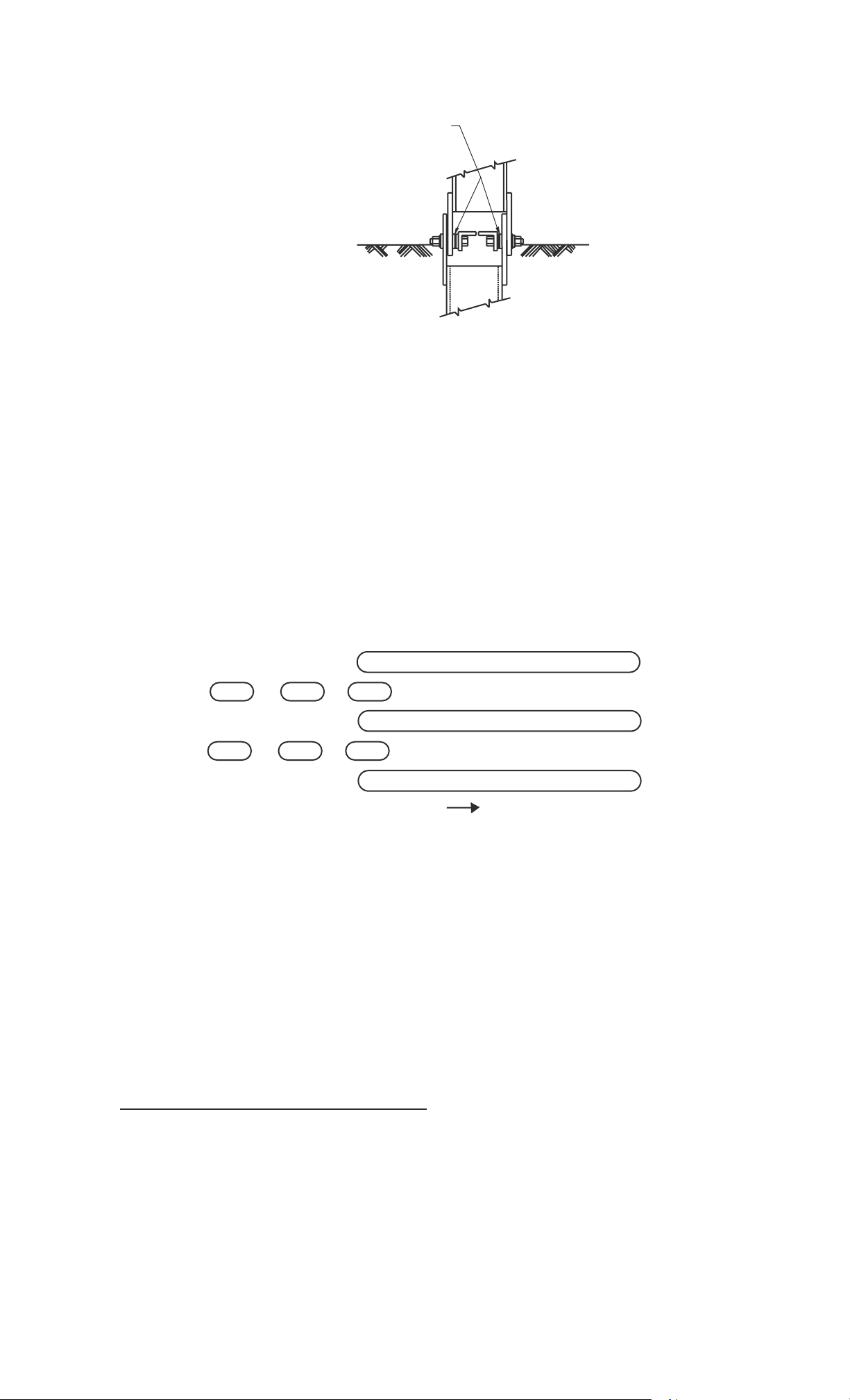
Place the two angle struts (PC-33879G) between post 1 and 2. See
Figure 4 .
In the 13/16" (21 mm) hole of Post No. 1 post plates, install a 3/4" x 3"
(19 mm x 75 mm) diameter hex head high strength bolt. The bolt is
placed through the strut and through the two post plates. A 3/4" (19 mm)
washer and a 3/4" (19 mm) lock washer are placed under the 3/4" (19
mm) hex nut.
In the 13/16" (21 mm) holes of Post No. 2 post plates, install a 3/4" x 3"
(19 mm x 75 mm) diameter hex head high strength bolt. The bolt is
placed through the strut and through the two post plates. A 3/4" (19 mm)
washer and 3/4" (19 mm) lock washer are placed under the 3/4" (19 mm)
hex nut. Two to three washers are stacked on the bolt between the strut
and the inside post plate to allow the strut to pass over the 3/8" (10 mm)
bolt head. See Figure 4.
There is no torque requirement for these bolts. They should be
tightened to a snug position.
Page 9
8
8
Stack 2-3 washers on 3/4" bolt
Between post plate & strut to allow
strut to pass over 3/8" bolt head.
FIGURE 4
INSTALLING WOOD BLOCKOUTS
AND RAIL PANEL
Guardrail panels (PC-30G and PC-39G and PC-69G) have two (2) sets of
slots. These slots should be between posts 1 and 2, 2 and 3, 3 and 4,
and 4 and 5. The guardrail panels should be installed so that the slot
guard attachment holes are at the end of the slots away from the end of
the terminal. See Figure 5.
Toward Post 1
FIGURE 5
The 12'6" (3.81 m) guardrail panel (PC-39G) or 25'0" (7.62 m) guardrail
panel (PC-69G) slots should be between posts 3 and 4 and posts 4 and
5.
The 12'6" (3.81 m) guardrail panel (PC-30G) anchor bracket holes will be
between post 1 and post 2.
12'6" (3 .81 m) PANEL OPTION:
At post location 7, splice and post bolt the 12'6" (3.81 m) rail panel
(PC-9G) to the run of guardrail with hardware provided by the standard
guardrail supplier.
The terminal rail should be lapped in the direction of traffic
unless the agency's policy dictates otherwise.
At post location 5, splice the 12'6" (3.81 m) rail panel to the 12'6"
(3.81 m) rail panel
Page 10

(PC-39G) with eight (8) 5/8" x 1 1/4" (16 mm x 32 mm) splice bolts and
hex nuts.
At post locations 4, 5, and 6 , bolt the rail panel and wood blockout to
the wood post using a 5/8" x 18" (16 mm x 460 mm) post bolt, a hex
nut, and a round washer. The washer is installed between the wood post
and the nut.
At post location 3, splice the 12'6" (3.81 m) rail panel (PC-39G) to the
12'6" (3.81 m) rail panel (PC-30G) with eight (8) 5/8" x 1 1/4"(16 mm x
32 mm) splice bolts and hex nuts. Bolt the rail panels and wood blockout
to the wood post using a 5/8" x 18" (16 mm x 460 mm) post bolt, a hex
nut, and a round washer. The washer is installed between the wood post
and the nut.
At post locations 1 and 2 , bolt rail panel to the wood posts using a
5/8" x 10" (16 mm x 255 mm) post bolt, a hex nut, and a round washer.
The washer is installed between the wood post and the nut.
The wood offset block should be secured to prevent it from
rotating . This can be done by toe nailing the block to the post or
the post to the block
nails should be installed approximately 3" (75mm) from the top
of the post or block, one on each side.
using 16d hot-dipped galvanized nails. The
25'0" (7 .62 m) PANEL OPTION:
At post location 7, splice and post bolt the 25'0" (7.62 m) rail panel
(PC-69G) to the run of guardrail with hardware provided by the standard
guardrail supplier.
At post locations 4, 5, and 6, bolt the 25'0" (7.62 m) rail panel
(PC-69G) and wood blockouts to the wood posts using a 5/8" x 18"
(16 mm x 460 mm) post bolt, a hex nut, and a round washer. The washer
is installed between the wood post and the nut.
At post location 3, splice the 25'0" (7.62 m) rail panel (PC-69G) to the
12'6" (3.81 m) rail panel (PC-30G) with eight 8 5/8" x 1 1/4"(16 mm x 32
mm) splice bolts and hex nuts. Bolt the rail panels and wood blockout to
the wood post using a 5/8" x 18" (16 mm x 460 mm) post bolt, a hex
nut, and a round washer. The washer is installed between the wood post
and the nut.
At post location 2, bolt the backup rail panel (PC-3G) to the HBA Top
Post using a 5/8" x 2" (16 mm x 50 mm) post bolt, a hex nut, and a round
washer. The washer is installed between the post and the nut. Do not
attach the rail to the post.
At post location 1, bo
5/8" x 2" (16 mm x 50 mm) post bolt, a hex nut, and a round washer.
The washer is installed between the post and the nut.
The wood offset block should be secured to prevent it from rotating. This
can be done by toe nailing the block to the post or the post to the block
using 16d hot-dipped galvanized nails. The nails should be installed
approximately 3" (75mm) from the top of the post or block, one on each
side.
lt the rail panel to the HBA Top Post using a
9
Page 11
10
INSTALLING SLOT GUARDS
Install the slot guards (PC-9960G) with the deflector angle closest to the
elongated slots. Each slot guard is bolted to the backside of the guardrail
panels with six (6) 5/8" x 1 1/4" (16 mm x 32 mm) splice bolts and hex
nuts. It is suggested that the slot guards and the cable anchor bracket
(PC-700A) be installed on the rail panels before going to the work site.
This will expedite the installation.
INSTALLING THE CABLE ANCHOR ASSEMBLY
The cable anchor bracket (PC-700A) is bolted to the backside of the
guardrail panel using eight (8) 5/8" x 1 1/2" (16 mm x 38 mm) hex bolts,
eight (8) hex nuts, and eight (8) round washers. The round washers are
installed between the bolt head and the rail panel on the traffic side.
Slide one end of the cable (PC-3000G) into the cable anchor bracket and
the other end between the upper and lower HBA posts at location 1.
Place a 1" (25 mm) washer on the end of the cable that extends through
the cable anchor bracket.
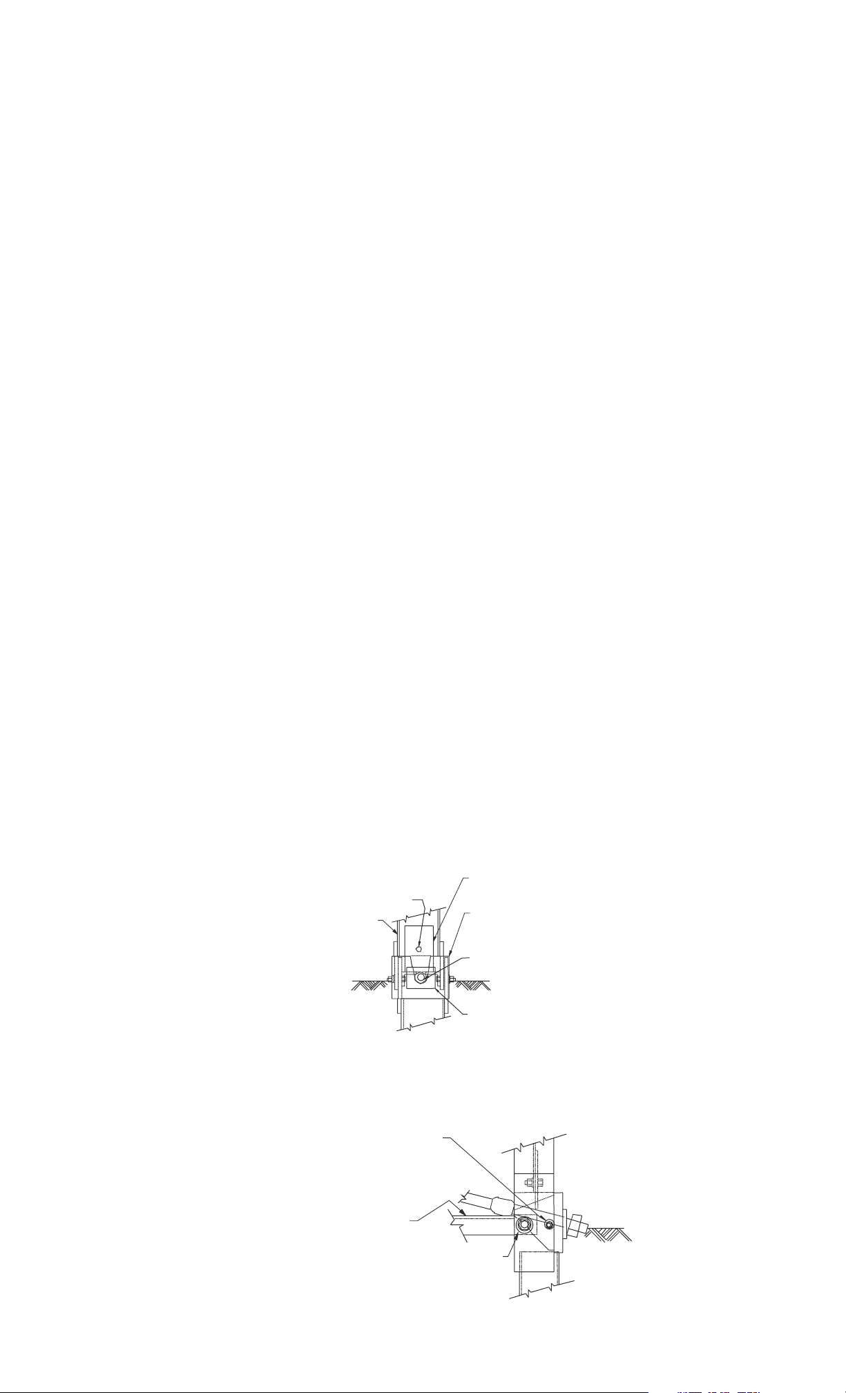
On Post No. 1, bolt the 4" x 5 3/4" x 1/4" (100 mm x 146 mm x 6 mm)
Cable Web Plate (PC-33881G) to the web of the
post with a 3/8" x 1 1/2"
(10 mm x 37 mm) hex head bolt, with a 3/8" (10 mm) washer under the
3/8" (10 mm) hex nut. The cable web plate should be pushing down on
the top of the cable anchor. See Figures 6 and 7.
After the Cable Web Plate is installed, place the bearing plate
(PC-33880G) with the open side of the V-notch pointing upward and the
plate washer (PC-9961G) on the end of the cable. See Figure 6. The
bearing plate should rest on the top of the flange of the HBA bottom post.
See Figure 7.
PC 33881G
Attaches to web of post #1
PC 4261G W/ PC 6405G & PC 4254G
Tr affic Side
PC 33880G
Install plate so slot
opening is at top
PC 3000G W/ PC 3910G each end
& PC 3900G opp end
FIGURE 6
PC 6321 W/ PC 4258, PC 4254 & PC 6405
Install with head on strut side
w/washer & lockwasher under hex nut
PC 33879G
PC 3718 W/ PC 3701, PC 4699 & PC 3704
Install with head on strut side
w/washer & lockwasher under hex nut
FIGURE 7
PC 9961G
Page 12

Secure each end of the cable with a 1" (25 mm) hex nut and tighten.
Restrain the cable with vise grip pliers at the end being tightened to avoid
twisting the cable. Make sure the nuts are tight and the cable is taut.
INSTALLING THE END SECTION
Install the end section (PC-907G) by connecting it to the end of the
guardrail panel with four (4) 5/8" x 1 1/4" (16 mm x 32 mm) splice bolts
and hex nuts.
11
Page 13

12
SRTTM/ HBATM6-POST SYSTEM
INSTALLATION CHECK LIST
STATE:
DATE:
PROJECT:
LOCATION:
The rail height is in accordance with the plans (generally 27 3/4"
[706 mm] above the finished grade).
The ears of the bottom HBA posts do not protrude more than 4"
(100 mm) above the finished grade measured by the AASHTO 5'0"
(1.5 m) cord method. Site grading may be necessary to meet this
requirement.
The 6" x 8" (150 mm x 200 mm) bearing plate at post 1 is correctly
positioned and the anchor cable is taut and correctly installed (it
should be rechecked after installation to be sure is hasn't relaxed).
The rail panel is not attached to the posts at location 2. No
rectangular washers are used on the face of the rail.
Slot guards are in place and oriented correctly.
Rail panels are oriented and lapped correctly.
Blockouts have been toe nailed to the posts.
The backfill material around the posts is properly compacted.
The Controlled Released Terminal (CRT) post has two 3-1/2"
(90 mm) breakaway holes (checked prior to installation). They
should be located parallel to the roadway with the bottom of the top
hole located approximately at the finished grade.
If paved, the material around posts 1 and 2 is rem
oved.
The recesses are not filled with compacted asphalt or concrete.
Page 14

MAINTENANCE/REPAIR
INSTRUCTIONS FOR
SRT
TM
/HBA
TM
6-POST SYSTEM
GUARDRAIL END TERMINAL
MAINTENANCE
Maintenance consists of periodically checking the system to see that the
cable is taut, the nuts have not been removed from the cable, and the
blockouts have not rotated.
REPAIR
(1)
At the accident site, setup necessary traffic control and then remove
any debris that has encroached onto the traveled way or shoulder.
Install any necessary delineation necessary for the damaged system.
Take inventory of the damaged system and determine what parts are
reusable and what parts need to be replaced.
(2)
Obtain those parts that need to be replaced.
(3)
With the replacement parts, return to the repair site. To expedite the
rail installation, it is suggested that any new rail panel(s) brought to
the repair site should have the slot guards already bolted to it to
minimize work zone repair time. The slot guards on the damaged rail
panel(s) can be removed back at the maintenance yard and used on
the next repair.
(4)
Disconnect and remove the damaged rail from the posts.
(5)
Remove any damaged Controlled Release Terminal (CRT) posts.
(6)
After the site has been cleared of damaged debris, the system can be
reconstructed following the installation instructions.
13
Page 15

Page 16

2525 Stemmons Freeway
ENERGY ABSORPTION SYSTEMS
Dallas, Texas 75207
888-323-6374 (USA only)
214-589-8140 (Outside USA)
www.energyabsorption.com
www.highwayguardrail.com
 Loading...