

Page 1

Reference
Power AMP
MANUAL
Page 2

THANK YOU
for purchasing a product from TRINITY Electronic Design.
The TRINITY Power Amp with its outstanding architecture sets new standards so that discerning music aficionados
can finally enjoy their most beautiful recordings as if it were the true to life original.
The TRINITY POWER AMP is parted in a voltage gain stage and a current gain stage with its own global feedback.
The voltage gain input stage is based on 16 voltage gain blocks, which work in parallel to reduce the noise level and
to increase the linearity close to the measurement limits.
The current output stage of the TRINITY Power Amp contains 168 output transistor pairs and 56 voltage regulators.
Two 480W Switch-Mode-Power-Supply modules drive two low noise 20Ampere Voltage regulator, which store
enough energy in a big capacity bank.
The TRINITY Power Amp is specified down to 2Ohm loads to work with all critical loudspeakers.
The real power bandwidth is above 500kHz at the maximum specified load.
Enjoy pure sound reproduction with our product.
Sincerely Yours
TRINITY Team
Page 3

Photo PA
Page 4

CONTENTS
Safety Instructions ................................................................................................. 5
Scope of Supply .........................................................................................................................................6
Transportation and Cleaning .......................................................................................................................6
Selecting the Power Voltage .......................................................................................................................7
Connecting and Starting ..............................................................................................................................7
Wiring Up.....................................................................................................................................................8
Technical descriptions ............................................................................................................................... .9
THE FINAL MEASUREMENTS.............................................................................................................. .20
Warranty...................................................................................................................................................... 27
Support.........................................................................................................................................................28
Page 5

SAFETY INSTRUCTIONS
1. Please read this operating manual carefully and observe all the instructions affixed to the appliance or written in
this manual.
2. Install this product on a stable surface and make sure that nobody can trip over the cables.
3. This product should only be connected to a power source indicated on the product. If you are unsure what power
source you have in your region, please contact your local power utility.
4. Never operate this product near water or with wet hands. If the product comes in contact with liquids,
immediately disconnect it from the power source.
5. To exclude the risk of an electric shock, please never expose the product to the rain or other source of liquid.
6. In thunderstorms, do not install the product or put it into operation.
7. Never attempt to open the appliance or repair it yourself. If you open or remove the enclosure, you may expose
parts that are subjected to dangerous levels of voltage. Any unauthorized opening of the appliance will cause the
warranty claim to become null and void.
8. Do not allow children to play with electrical appliances without adult supervision. Children do not always
recognize the possible risks and consequences.
Page 6

SCOPE OF SUPPLY
The scope of supply comprises:
• TRINITY Power AMP
• 1 x Flight Case, weight: 59kg, dimension: 80cm, 60cm, 40cm
TRANSPORTATION AND CLEANING
Please only transport the parts listed in the scope of supply in the supplied flight case and use the supplied cotton
gloves when unpacking and installing the appliances to avoid scratching the enclosures.
Clean the surfaces using the supplied microfiber cloth: immerse the cloth in lukewarm water containing no
detergents and then carefully wipe the surface when the cloth is almost dry.
Never use chemical or aggressive detergents.
Page 7

SELECTING THE POWER VOLTAGE
The implemented wide-range switched mode power supply modules allow an operation from 100Vac to 240Vac.
The two fuses on the primary side are placed inside of these modules.
CONNECTING AND STARTING
To install the TRINITY Power AMP, select a stable, level surface directly next to the turn table so that the connecting
cable to the tone arm is as short as possible. Avoid placing the appliance in direct sunlight and never place the
modules directly next to radiators or fan heaters.
Protect all supplied parts from humidity and moisture.
Only wire up the components when the device is switched off.
Page 8

WIRING UP AND Select the Stereo/Mono Mode
1. Disconnect the Power Amp from the power source. Never disconnect any wires unless the device is switched off.
2. Connect the Power Amp MONO input to the audio source for Mono-bridge mode.
3. Connect the Power Amp Left & Right inputs to the audio sources for stereo mode.
4. To select the Stereo Mode, press the selection push button on the back of the amp.
5. Connect the Power Amp to the loudspeakers. Choose the red and white connectors for the stereo mode and use
the two red connectors for the Mono-bridge mode.
Page 9

The POWER AMP
“As no cable can improve any signal which it is passing (unless it is filtering out some other problem that should
not be there) it must be concluded that the best cable is no cable. Moreover, as no amplifier can improve the
accuracy of the signal which it is passing, the only conclusion which can be drawn is that the combination of
amplifier and cable can only degrade the signal. However, as we must use an amplifier and a cable, art and
science are both employed in order to minimise the inevitable degradation.”
“Loudspeakers”, Philip Newell and Keith Holland
Objectives of an ideal power amp
An ideal audio amplifier should have the following characteristics:
- Infinity Power Bandwidth
- Infinity Output Current
- Zero Output Impedance
- no Harmonic Distortions
- no Intermodulation Distortions
- no Transient Intermodulation Distortions
- no Noise
- cost nothing
Page 10

Everybody will agree to design an ideal amp is impossible, but how close a design comes to these requirements
determine the real quality of the amp.
The development target of the TRINITY POWER AMP was to get as close as possible to these objectives. Since the
maximum output power is not a sound relevant parameter, we decided to build a moderate power amp, which is
nevertheless able to drive 2Ohm loads almost distortion free. The Power Amp should have the lowest distortions,
the lowest noise, the highest power bandwidth and a huge phase margin for complex loads to avoid that the amp
declines the excellent measurement results of our TRINITY PREAMP, DAC or PHONO Stage.
Like in all of our products only sound relevant parameters are the focus in our development.
The signal to noise ratio should be in the range that there is no noise or hum at full volume in any kind of
loudspeakers including high efficiency horn loudspeakers.
There are amplifiers on the market, which uses an error correction loops to reduce the THD like the one described
here: http://www.cordellaudio.com/poweramp/mosfet.shtml
Such a compensation needs an additional loop and will work fine with steady state signals like a sine wave, but
music is much more complex than that and the amp has to drive a very complex load, which can have a negative
influence on such additional loops.
The better way is, if the amp has no distortion at all, than there is no need to implement an additional error
correction loop. That is the reason why we have realized the loops in the TRINITY Power AMP in a “classical”
design.
Less is more.
Page 11

Stability & Output Impedance
From the theory we know an amplifier is always stable on all complex loads, if the “open loop” output impedance is
zero. Zero is impossible, but we can reduce the output impedance, if we use more output transistors in parallel.
Therefore 168 pieces of NPN/PNP pairs are working in parallel in each of the TRINITY Power Amplifier. That means
overall 336 high frequency output transistors!!!!
If we close the loop the open loop output impedance is reduced by the open loop gain to the closed loop output
impedance. This closed loop output impedance determines the damping factor, which is the ratio of the speaker
impedance and the closed loop output impedance. Amps with higher damping ratio can control the huge voice coils
of the bass chassis much better. Figure 1 shows the simulated output impedance of a TRINITY Power Amplifier
(Edition version). The 1µOhms output impedance at 10Hz, which is related to a damping factor of almost 10.000.00
for an 8Ohm loudspeaker, is unique.
Page 12
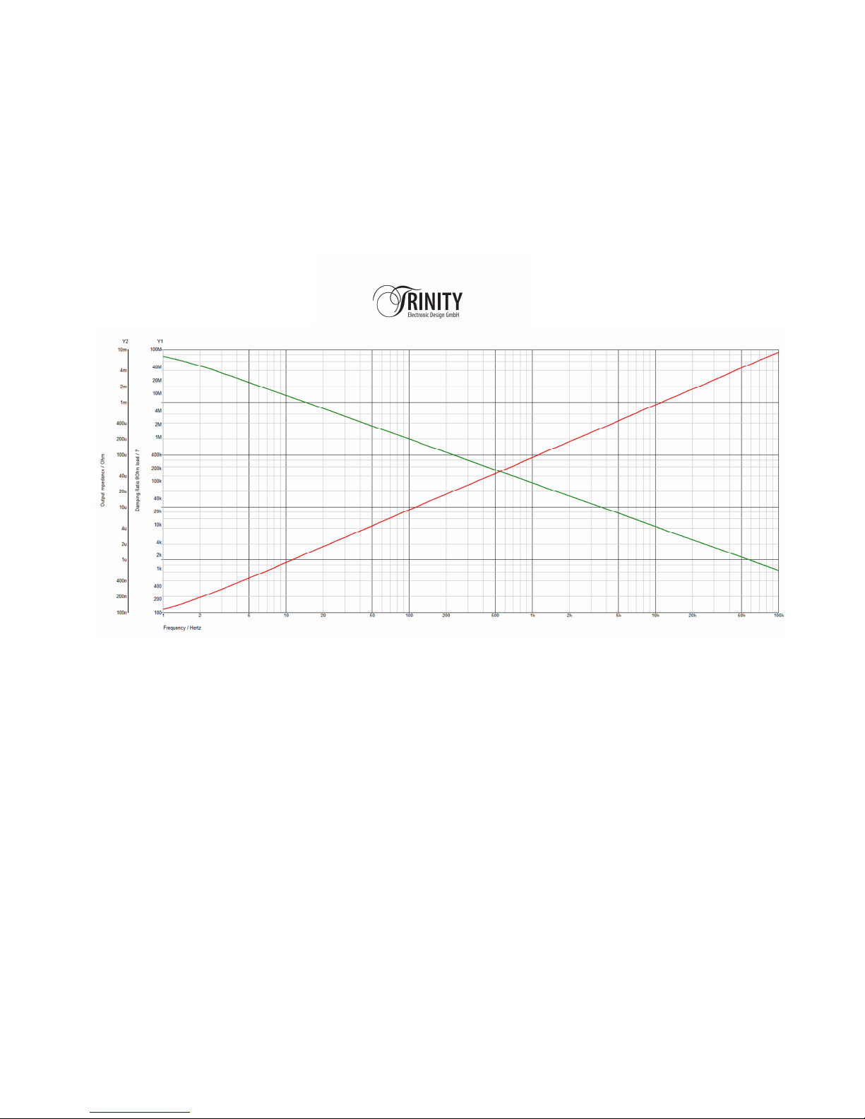
Figure 1 Simulated Closed Loop Output Impedance & Damping Ratio for an 8Ohm loudspeaker
Page 13
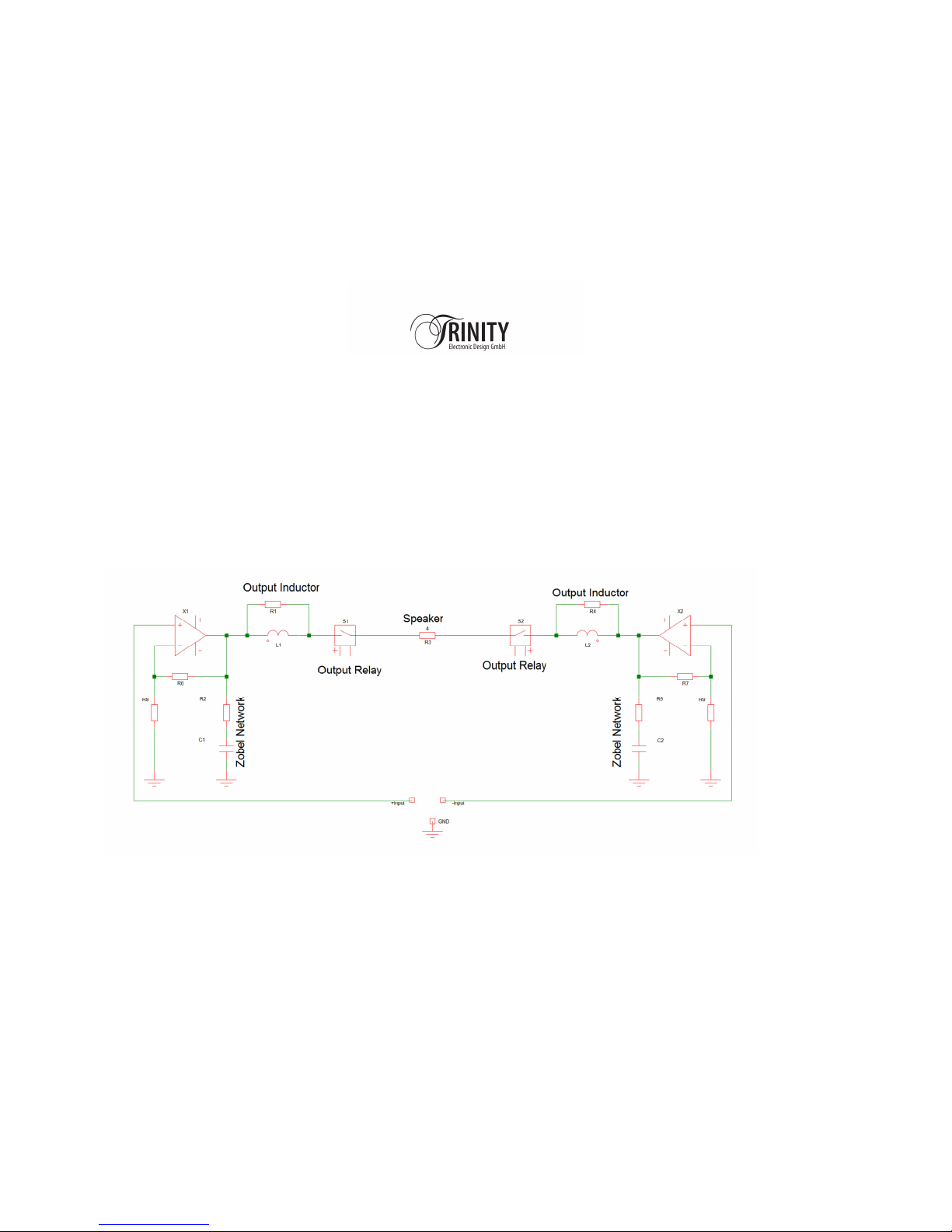
Normal Output Stage
This outstanding damping ratio is only possible with a different design of the output stage.
Figure 2 shows the arrangement of the output stage of a common audio amplifier.
- high over all voltage gain
- a shunt Zobel network for stability into inductive loads
- a series output inductor//damping resistor for stability into capacitive loads
- a relay for DC-offset protection
Figure 2 Normal output stage of a power amplifier
Page 14
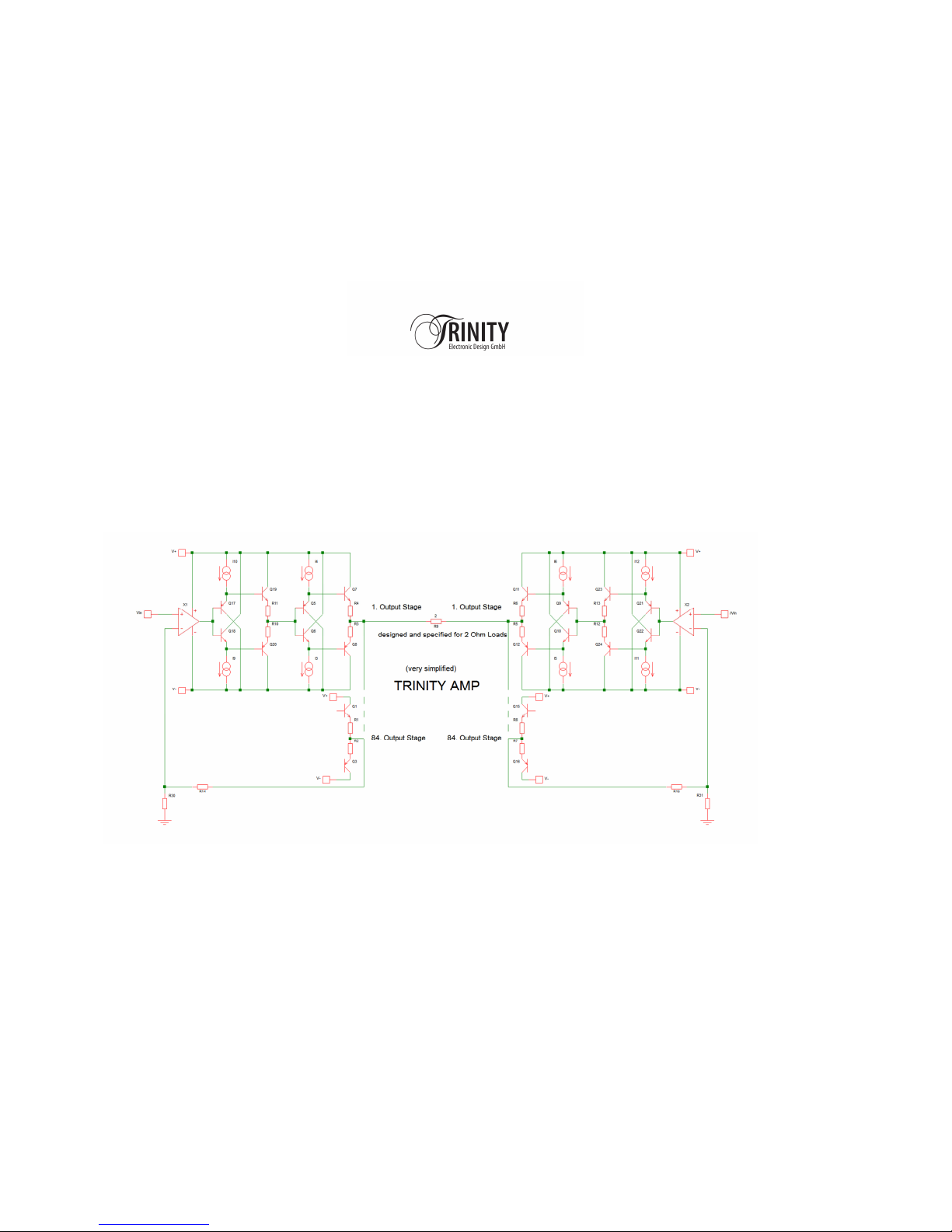
TRINITY Power AMP Output Stage
Figure 3 shows the simplified design of the output stage of a TRINITY Power AMP
- low voltage gain of 2 in the current output stage
- no shunt Zobel network
- no series output inductor/damping resistor
- no relay for DC-offset protection
Figure 3 TRINITY Power AMP output stage
Page 15

THE FINAL MEASUREMENTS
All TRINITY devices are shipped with a complete measurement protocol and not with some “typical” marketing
values published on the web page or in the data sheet.
What you see (in the measurement results) is what you get.
The measurements are done after a burn-in of 48hours.
The most of the measurements are showing the worst case, with the TRINITY Power AMP running at the maximum
input voltage and driving the lowest load resistor.
By the way in stereo mode the TRINITY Power Amp can run even on 1Ohm loads!!!!
Page 16
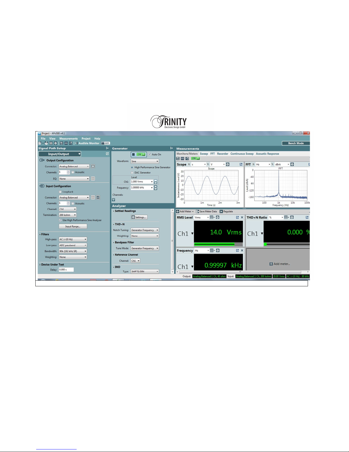
FFT Voltage Gain Stage 1kHz, 1Vrms Input Voltage,
all distortion
s are below
-
140dB!!!!!
Page 17
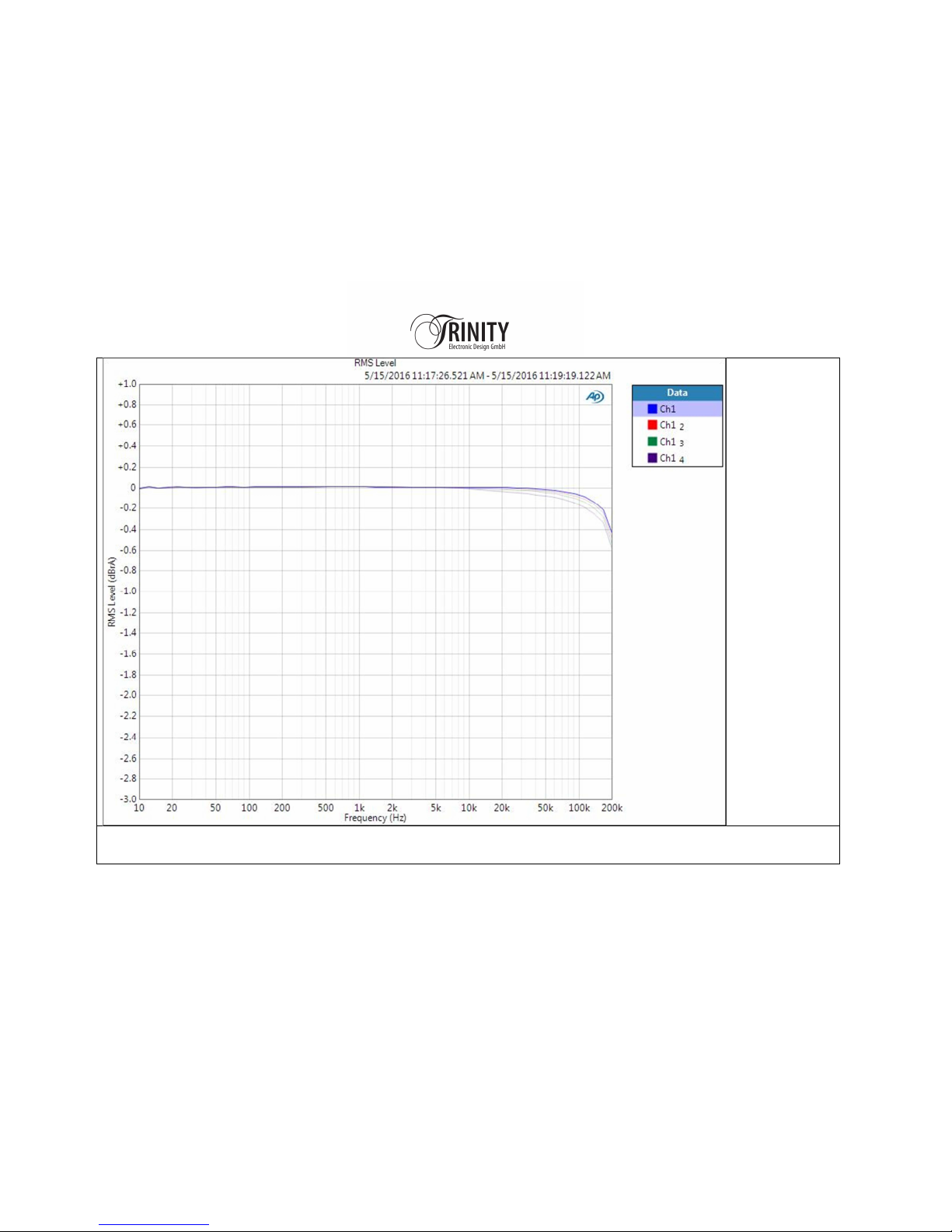
FREQUENCY RESPONSE of the Complete Power Amp 25Vrms_No Load_8Ohm, 4Ohm & 2Ohm,
0.5dB at 200kHz at full load, caused by the extreme low output impedance all curves lay on the top of each other
Page 18
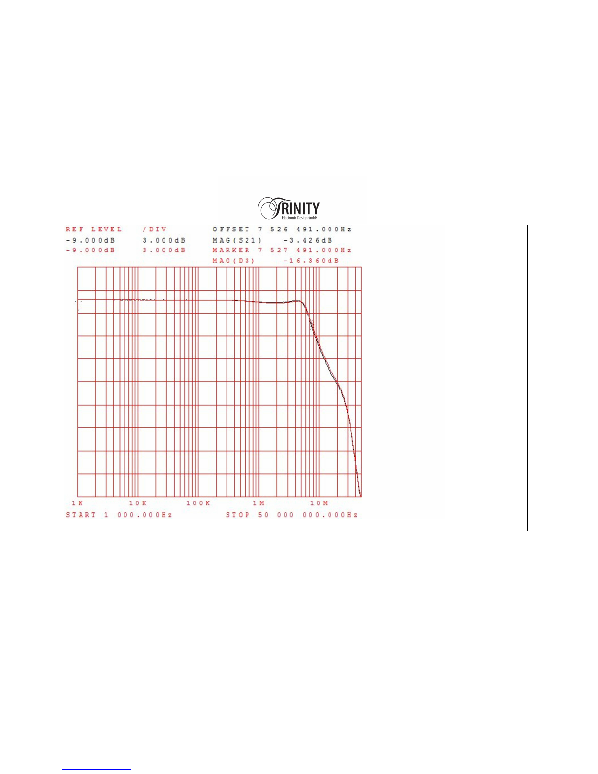
Small Signal - Frequency Response of the Current Gain Stage 3dB Corner Frequency at 7.5MHz
Page 19
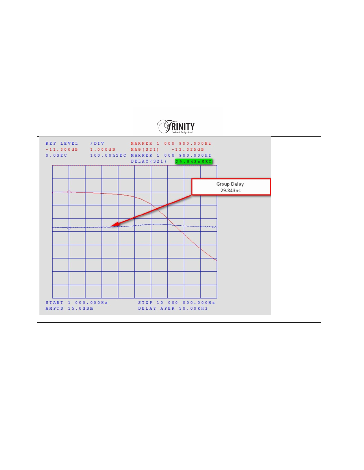
Small Signal - Group Delay Response of the Current Gain Stage is 29.843ns!!!!
Page 20
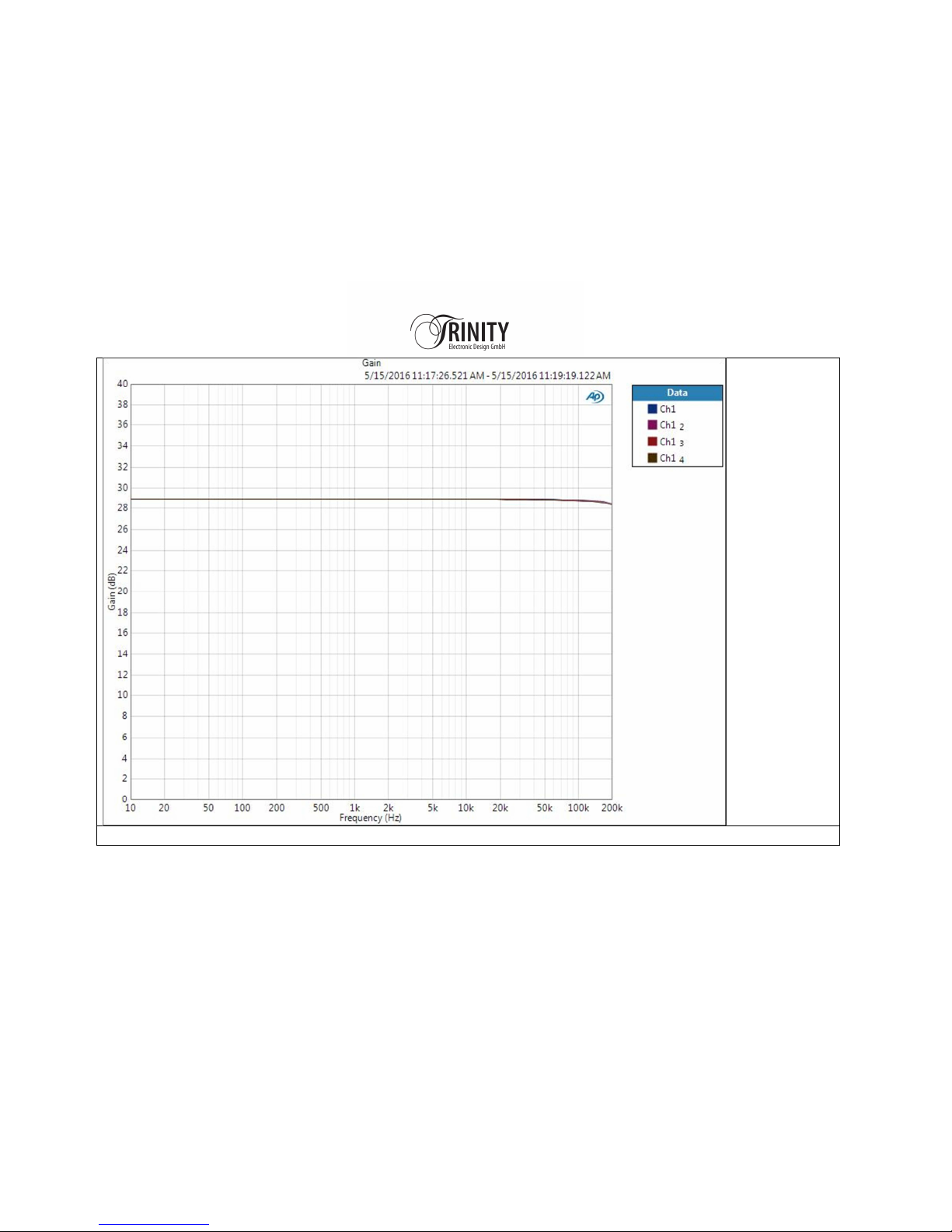
GAIN 25Vrms_No Load_8Ohm, 4Ohm & 2Ohm
Page 21
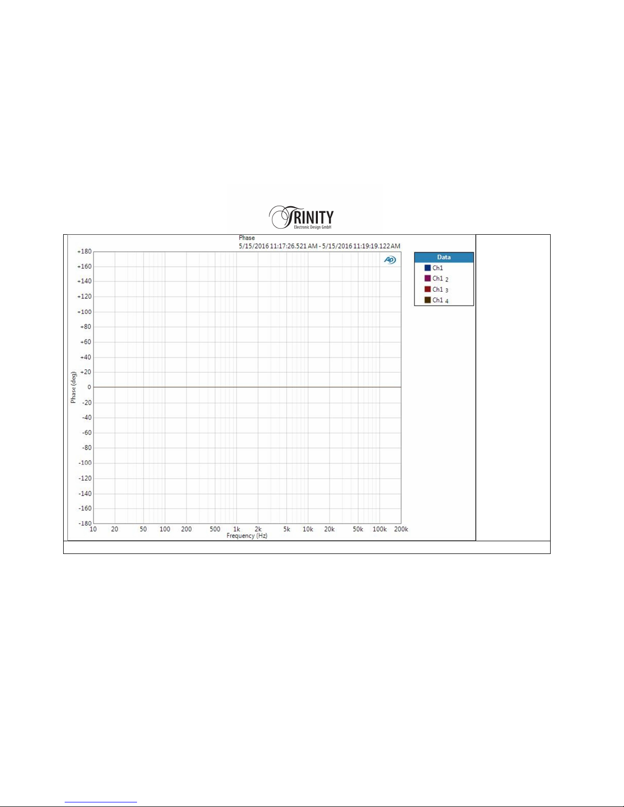
Phase 25Vrms_No Load_8Ohm, 4Ohm & 2Ohm
Page 22
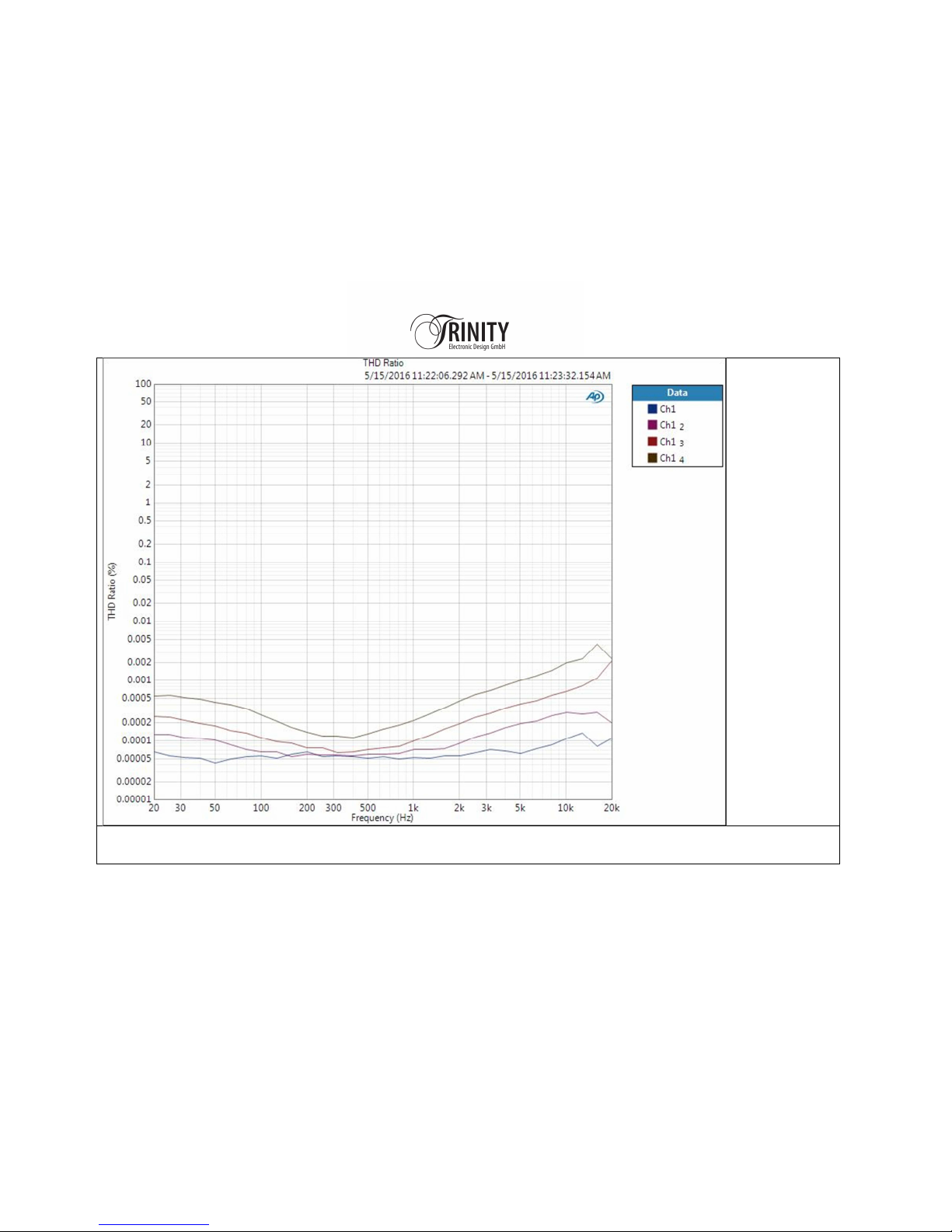
THD vs. Frequency 25Vrms_No Load_8Ohm, 4Ohm & 2Ohm all Harmonics up to 100kHz are counted
In the worst case the THD are below 0.004% at 20kHz at full power into 2Ohms
Page 23
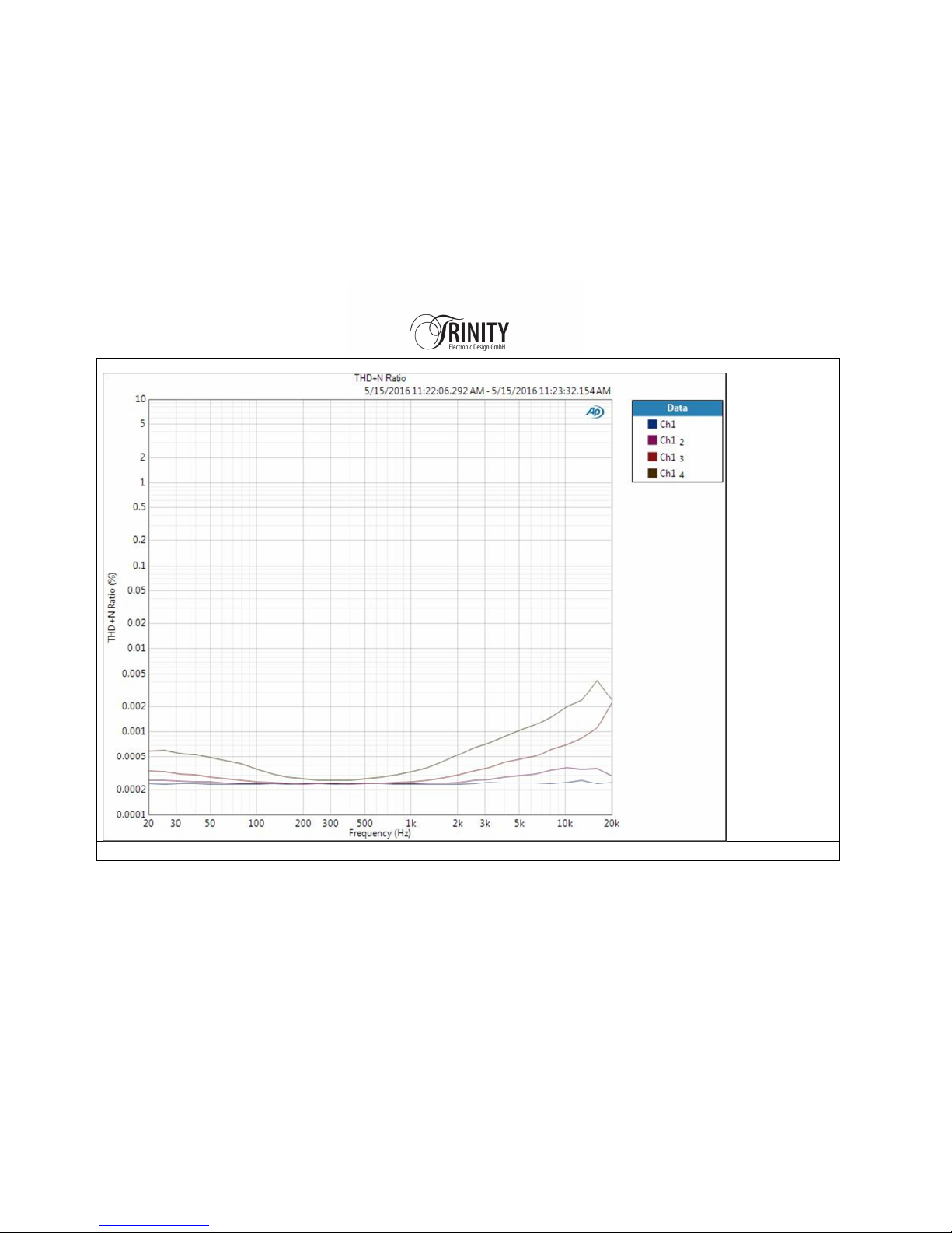
THD & Noise vs. Frequency 25Vrms_No Load_8Ohm, 4Ohm & 2Ohm all Harmonics up to 100kHz are counted
Page 24
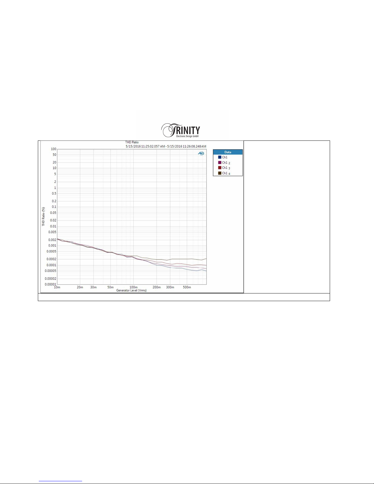
THD vs. Input Level 1kHz
No Load
_
8Ohm
,
4Ohm
& 2Ohm
Page 25
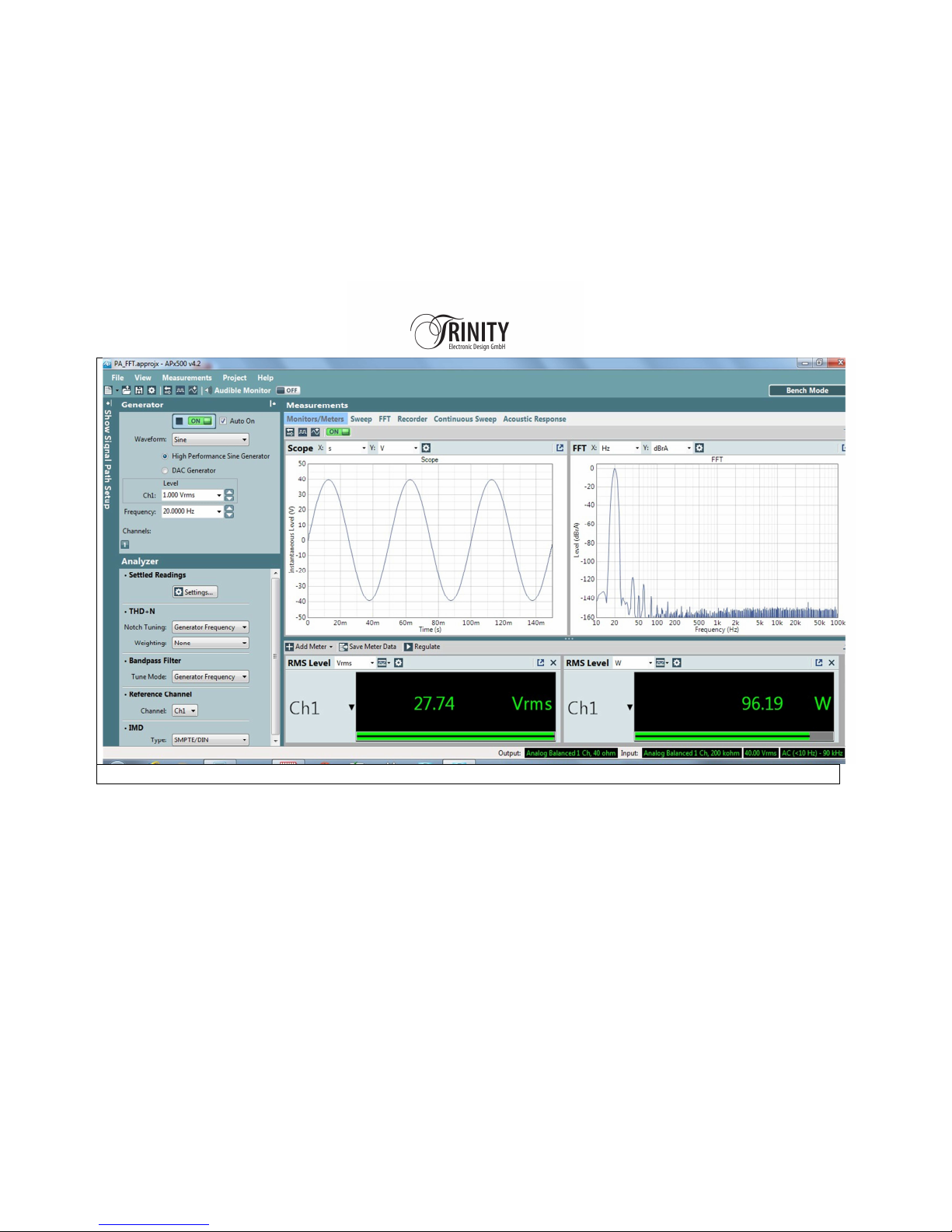
FFT 20Hz 100W into
8Ohm
Page 26
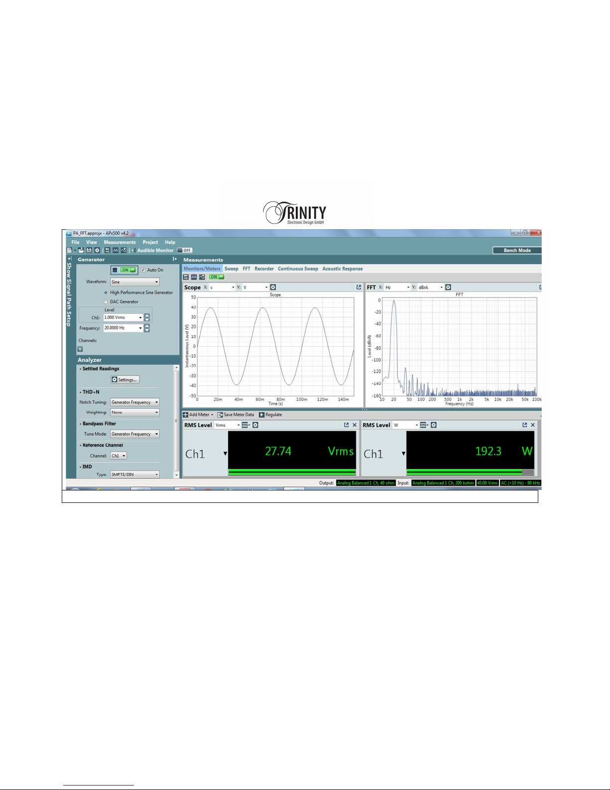
FFT 20Hz 200W into 4Ohms
Page 27
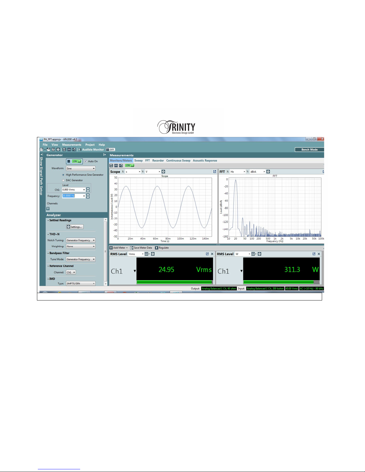
FFT 20Hz
30
0W into 2Ohms
Page 28
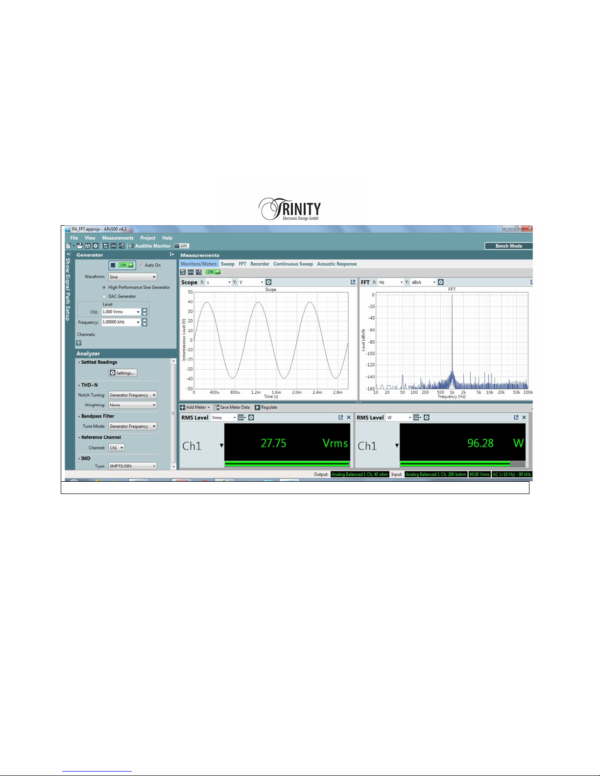
FFT 1kHz 100W into 8Ohms
Page 29
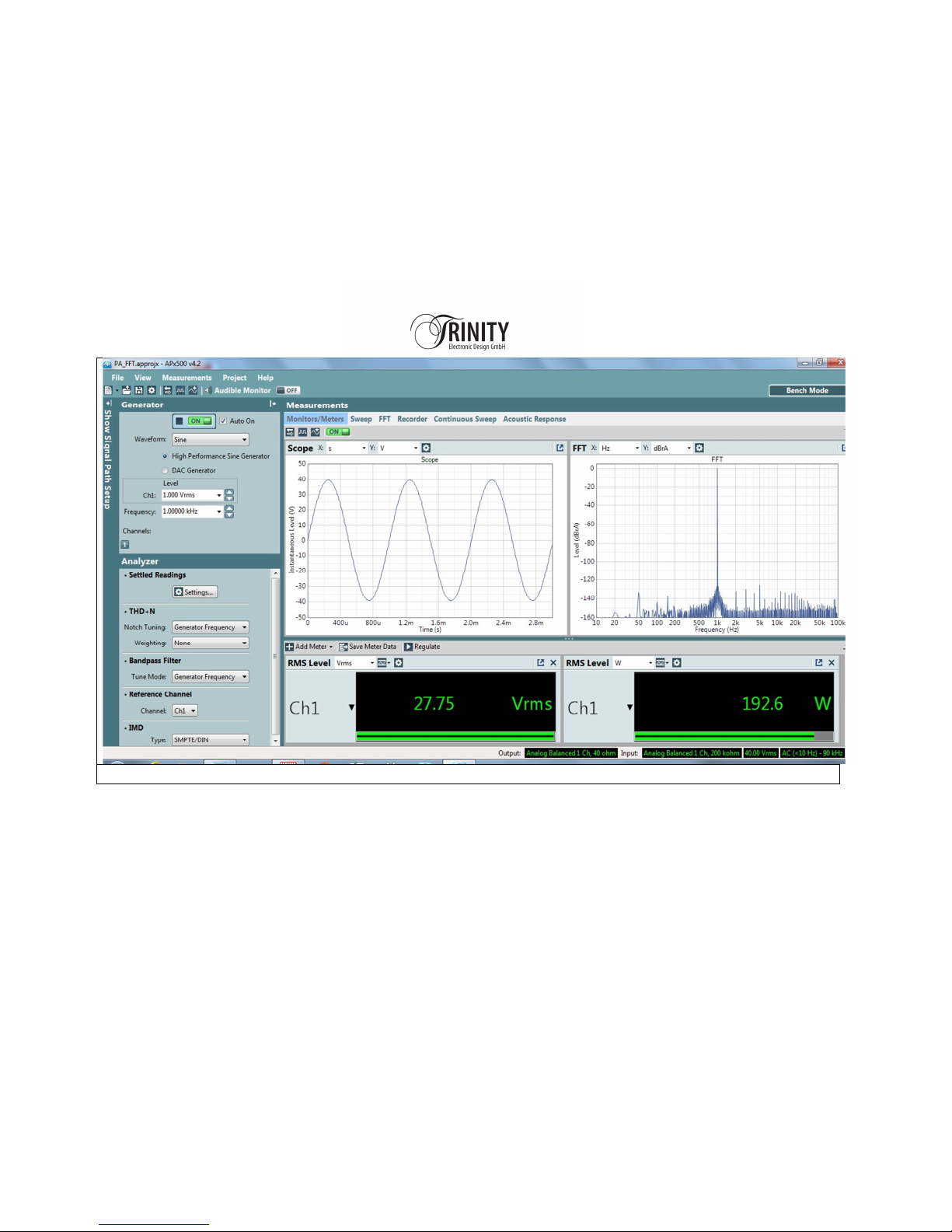
FFT 1kHz 200W into 4Ohms
Page 30
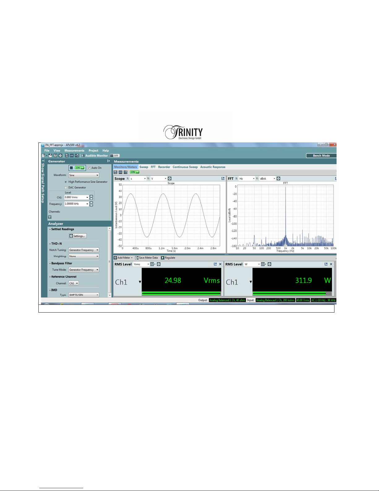
FFT 1kHz 300W into 2Ohms
Page 31
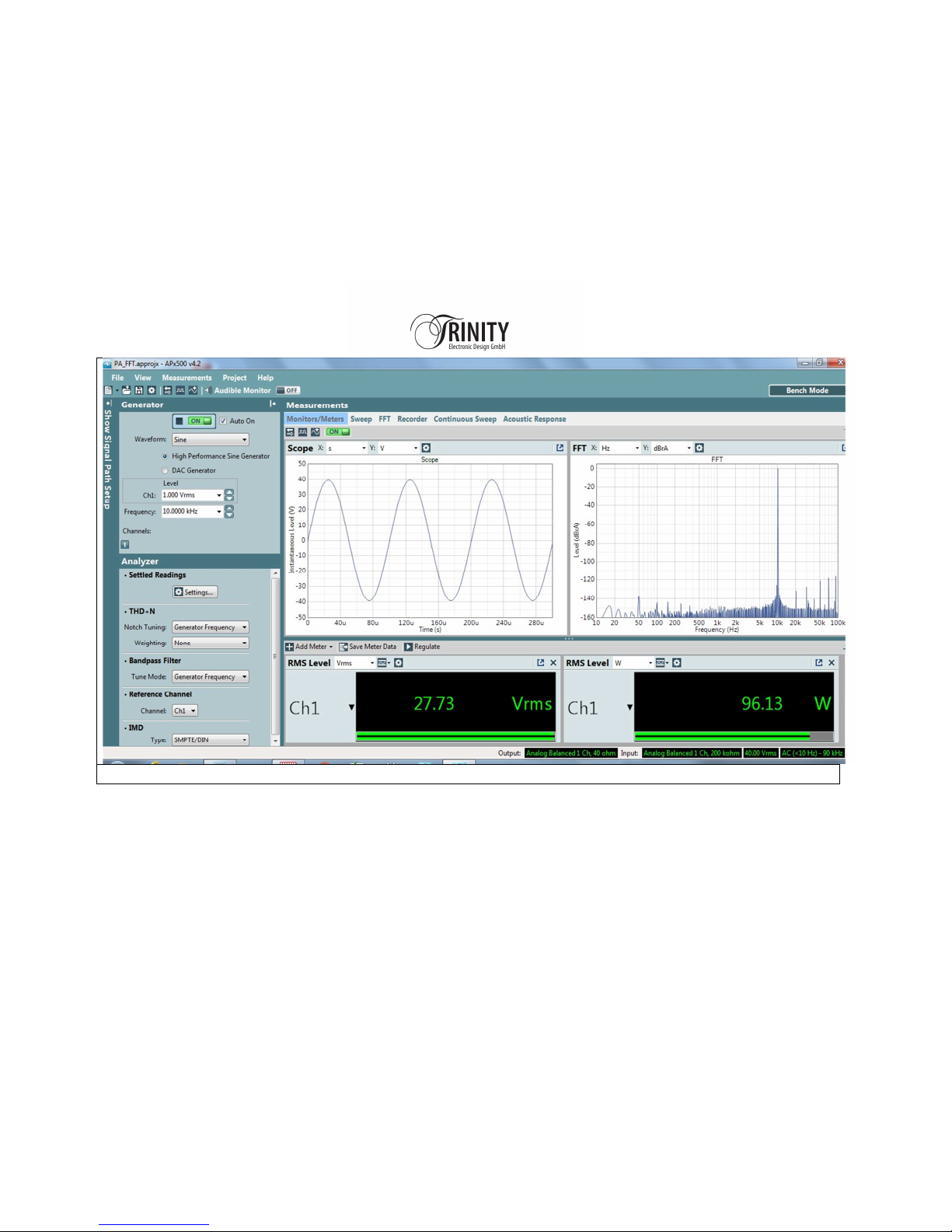
FFT 10kHz 100W into 8Ohms
Page 32
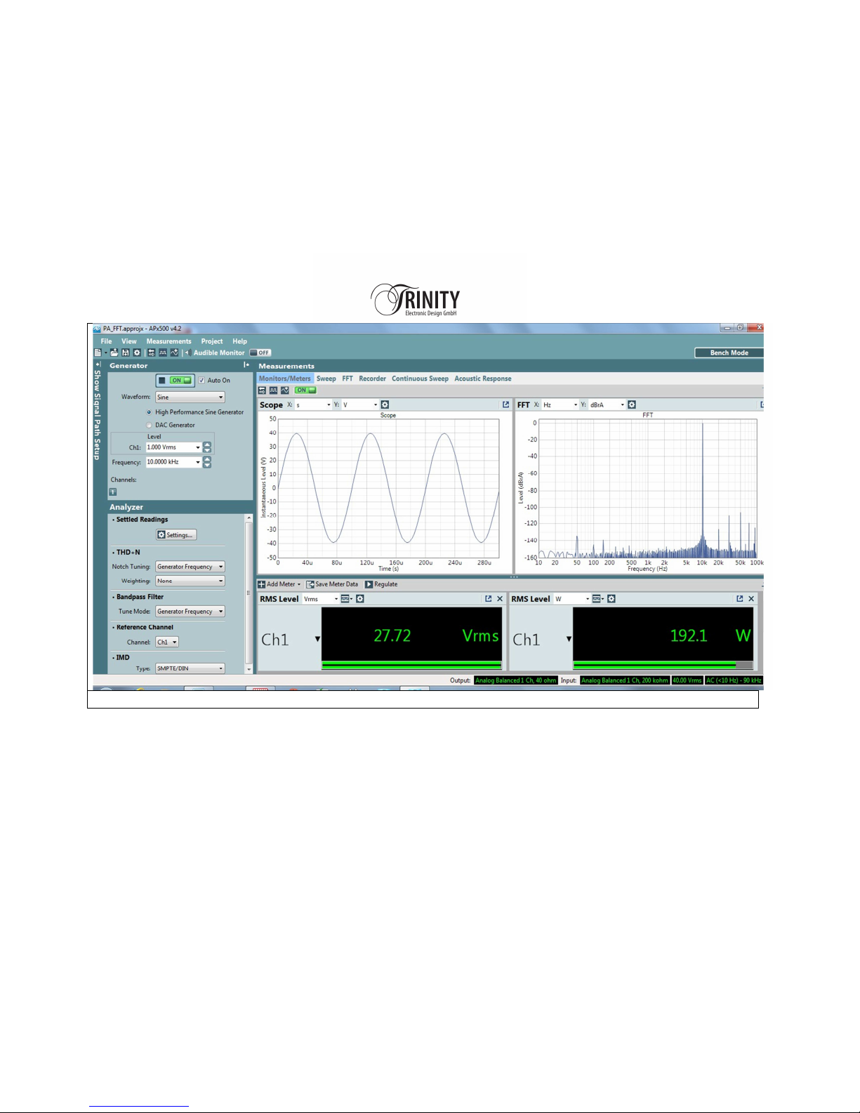
FFT 10kHz 200W into 4Ohms
Page 33
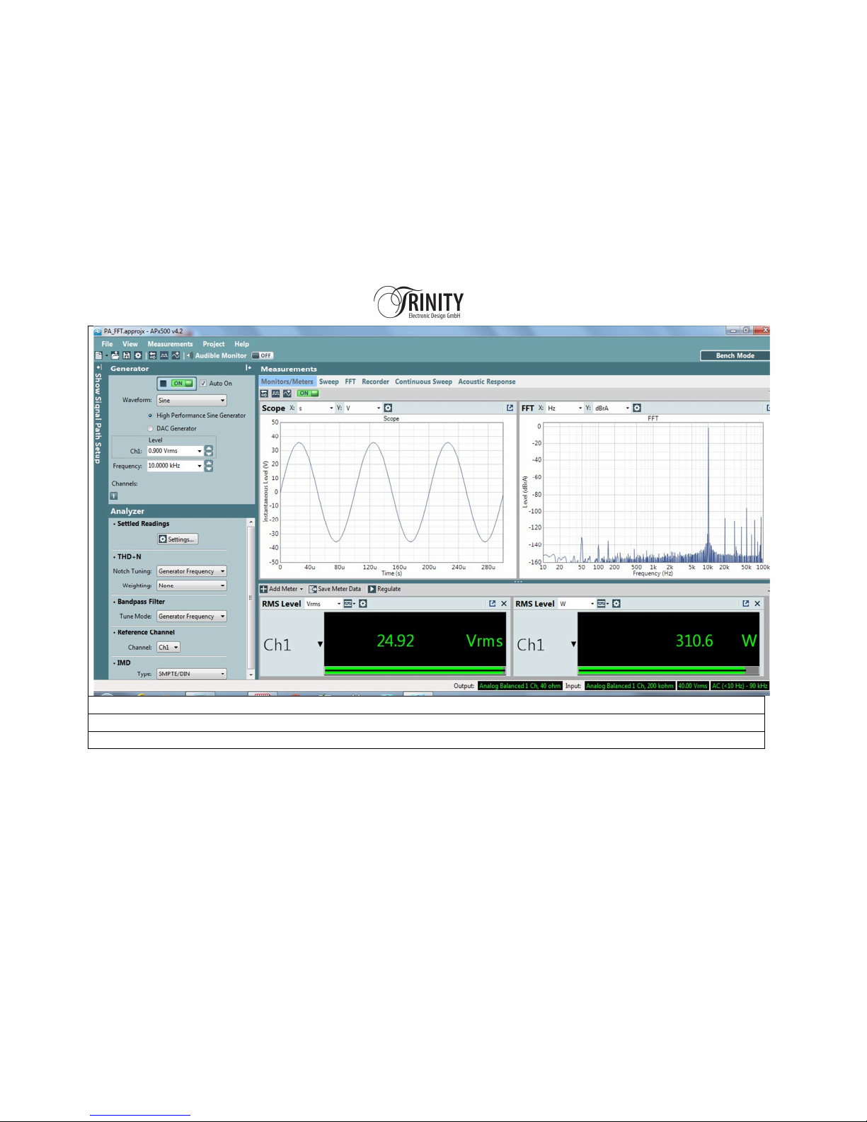
FFT 10kHz
3
00W into
2
Ohms
Page 34
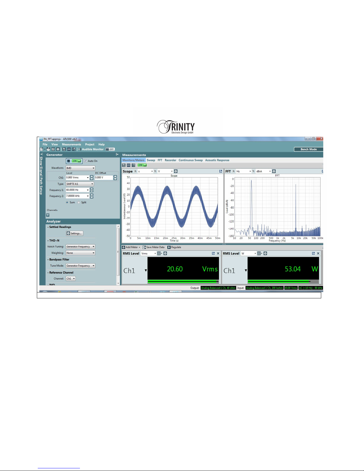
FFT_IMD_SMPTE_4
-
1 into 8Ohms
Page 35
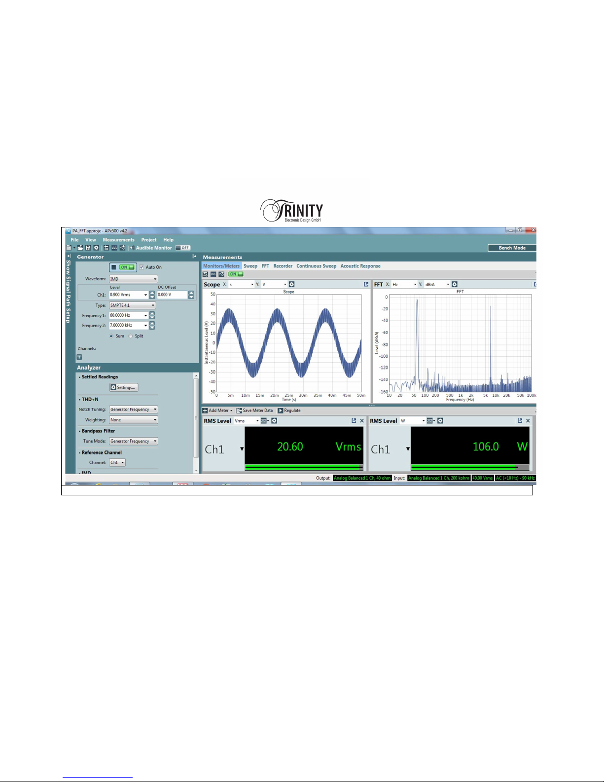
FFT_IMD_SMPTE_4
-
1 into
4
Ohms
Page 36
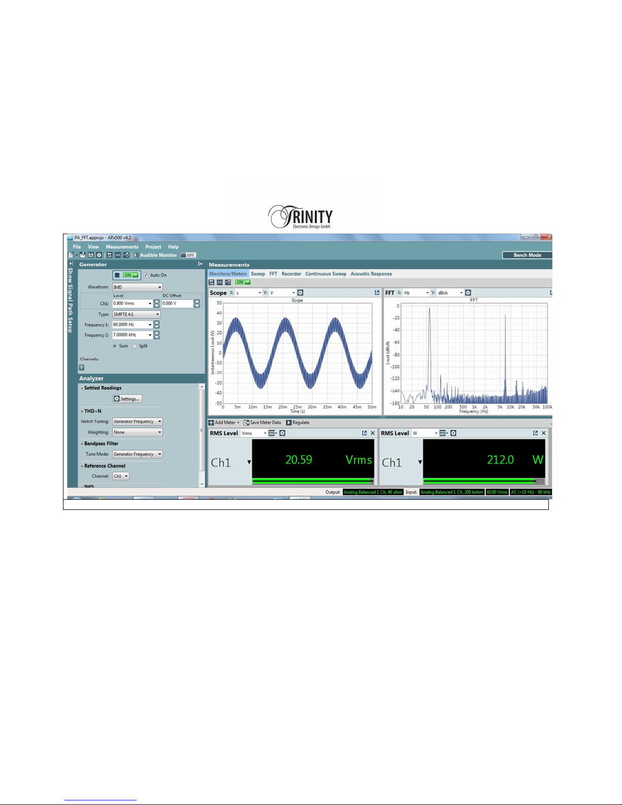
FFT_IMD_SMPTE_4
-
1 into
2
Ohms
Page 37

WARRANTY
The warranty period of the Trinity Power AMP is 2 years.
• Within the warranty period, any material and production defects will be rectified according to the following
conditions:
• The warranty period begins with the purchase of the product and only applies to first buyers.
• A warranty claim is only valid if defects originating from material or manufacturing defects occur, but not as the
result of natural wear and tear. In case of justified claims that occur during the warranty time, we will either
repair the affected component free of charge or replace it at our discretion. In so doing, we are entitled to also
supply a successor model in the interests of technical progress. Any further claims, in particular compensation
damage of any nature, are excluded.
• The warranty period is not extended by any work performed during the warranty period, neither for replaced nor
repaired components.
• Any improper handling or interventions by persons not authorized by TRINIT Electronic Design GmbH will render
the warranty claim null and void. This also applies to damage arising from improper connection or use.
• The warranty excludes transportation damage that must be claimed immediately from the forwarding agency
(railway, post, carrier). Any scratches on the enclosure or other visible defects must be reported to the dealer
within 3 days.
• The provisions of the German product liability law and comparable foreign regulations remain unaffected,
provided they are inalienable. We retain the right to make technical changes in the interests of technical progress
Page 38

SUPPORT
If you have any questions relating to installation, operation or options, we will be pleased to answer them.
TRINITY Electronic Design GmbH
Johann Wieser Ring 11
8609 Aschheim, Germany
Tel. +49 (0) 89 – 20186577
E-mail. [email protected]
Internet: http://www.trinity-ed.de
 Loading...