

Page 1

ENERGY ABSORPTION SYSTEMS
ET Plus
Guardrail End
Treatment
Assembly Manual
Part No. 620292B Revised March 2010
®
350
Page 2

ET-PLUS™ Systems
Guardrail End Treatment
Instructional Manual
Trinity Highway Products, LLC.
2525 Stemmons Freeway
Dallas, Texas 75207
IMPORTANT: These instructions are to be used only in
conjunction with the installation of the ET-PLUS
These instructions are for standard installations specified by
the appropriate state/specifying agency. In the event the
specified systems installation requires or involves special
circumstances, contact the appropriate state/specifying
agency before proceeding. Trinity Highway Products, LLC.
representative is available for consultation, if required.
This Manual must be available to the workers at all times. For
additional copies, contact Trinity Highway Products, LLC. at
All information, illustrations, and specifications in this Manual are based
on the latest ET-PLUS™ systems information available at the time of
printing. We reserve the right to make changes at any time.
www.highwayguardrail.com 1 Revised: October 5, 2009
800-527-6050.
™
systems.
Revised: March 2010
Page 3
CUSTOMER SERVICE CONTACTS
Trinity Highway Products, LLC is committed to the highest level of customer
service. Feedback regarding the ET-PLUS™ systems, their installation
procedures, supporting documentation, and performance is always welcome.
Our goal is to enhance highway safety through innovation. Additional
information for materials and product specifications can be obtained by
calling the telephone numbers or writing to the email address below:
TRINITY HIGHWAY PRODUCTS, LLC:
Telephone:
800-644-7976 (U.S. Calls)
+1-214-589-8140 (International)
E-mail: [email protected]
REGIONAL TELEPHONE CONTACTS:
Dallas, Texas 800-527-6050
Centerville, Utah 800-772-7976
Elizabethtown, Kentucky 800-282-7668
Girard, Ohio 800-321-2755
Orangeburg, South
Carolina
800-835-9307
SUGGESTED SAFETY RULES FOR INSTALLATION
- MAINTENANCE - REPAIR
Always keep this Manual in a location where it is easily accessed by persons
who install, maintain, or repair the ET-PLUS™ systems.
SAFETY SYMBOLS
Below are the safety symbols that may appear on the ET-PLUS™ systems or
in the documentation. Read the entire Manual for suggested safety,
assembly, installation, maintenance, repair, and service information.
* IMPORTANT SAFETY INSTRUCTIONS *
SYMBOL MEANING
SAFETY ALERT SYMBOL
Indicates Danger, Warning, or Caution. Failure to
read and follow the Danger, Warning, and Safety or
Caution indicators could result in serious injury or
death to the workers and/or bystanders.
WARNING – READ MANUAL
Read the Manual(s) and follow all warnings and
safety instructions. Failure to follow this warning
could result in serious injury or death to the workers
and/or bystanders.
www.highwayguardrail.com 2 Revised: March 2010
Page 4
WARNINGS AND CAUTIONS
Read all warnings, cautions, and instructions before installing/
maintaining/repairing the ET-PLUS™ systems.
IMPORTANT: READ SAFETY INSTRUCTIONS THOROUGHLY
AND FOLLOW THE SAFE OPERATION PRACTICES WHILE
INSTALLING THE ET-PLUS™ systems. Failur e to foll ow this warnin g
could result in serious injury or death to the workers and/or
bystanders.
WARNING: Read the instructions carefully. Be familiar with the
complete instructions for the ET-PLUS™ systems before installing,
maintaining, or repairing the ET-PLUS™ systems. Failure to follow
this warning could result in serious injury or death in the event of a
collision.
WARNING: Ensure that the necessary traffic control is setup and any
debris that has encroached onto the traveled way or shoulder has
been removed, before beginning installation or repairs. Failure to
follow this warning could result in serious injury or death in the event
of a collision.
WARNING: Be sure adequate time is available for complete
installation, before beginning the installation process. Failure to
follow this warning could result in serious injury or death in the event
of a collision.
WARNING: Do NOT perform installation, maintenance, or repair of
the ET-PLUS™ systems when tired, ill, or under the influence of
alcohol, drugs, or medication. Failure to follow this warning could
result in serious injury or death in the event of a collision.
WARNING: Do not install, maintain, or repair the ET-PLUS™
systems, until you have read this Manual thoroughly. Please call
Trinity Highway Products, LLC at 800-644-7976, if you do not
understand the installation instructions. Failure to follow this warning
could result in serious injury or death in the event of a collision.
WARNING: Use only Trinity Highway Products’ parts on the ETPLUS™ systems for installation, maintenance, or repair. The
installation or co-mingling of unauthorized parts is strictly prohibited.
Failure to follow this warning could result in serious injury or death in
the event of a vehicle impact with a system that has not been
accepted by the Federal Highway Administration (“FHWA”). The ETPLUS™ systems and its component parts have been accepted for
state use by FHWA. However, a co-mingled system has not been
accepted.
WARNING: Do NOT modify the ET-PLUS™ systems in any way.
Failure to follow this warning could result in serious injury or death in
the event of a collision.
WARNING: Do NOT perform installation, maintenance, or repair, if
the ET-PLUS™ systems site, shoulder, or traveled area is covered or
encroached by road debris. Failure to follow this warning could result
in serious injury or death in the event of a collision.
WARNING: Safety measures, incorporating traffic control devices,
must be used to protect all personnel, while at the installation,
maintenance, or repair site. Failure to follow this warning could result
in serious injury or death to the workers and/or bystanders. .
WARNING: Ensure that the entire work zone site is visible at all
times. Failure to follow this warning could result in serious injury or
death to the workers and/or bystanders.
WARNING: Use caution when working near public roads. Be mindful
of vehicles in motion nearby. Failure to follow this warning could
result in serious injury or death to the workers and/or bystanders.
WARNING: Ensure that all Guardrail products and delineation used
meet all federal, state/specifying agency, and local specifications.
Failure to follow this warning could result in serious injury or death in
the event of a collision.
www.highwayguardrail.com 3 Revised: March 2010
Page 5
WARNING: Ensure that your installation, repair, and maintenance
meet all appropriate Manual on Uniform Traffic Control Devices
(MUTCD) and local standards. Failure to follow this warning could
result in serious injury or death in the event of a collision.
WARNING: Ensure that the Guardrail you install is terminated, as
dictated by the state/specifying agency, pursuant to FHWA
acceptance. Failure to follow this warning could result in serious
injury or death in the event of a collision.
WARNING: Do NOT install SYTP™ at location 1. Failure to
follow this warning could result in serious injury or death in the
event of a collision.
WARNING: Do NOT install 6’0” CRT post at location 1. Failure to
follow this warning could result in serious injury or death in the
event of a collision.
WARNING: Do NOT bolt the rail panel to the post at location 1 in
any of the ET-PLUS™ systems. Failure to follow this warning
could result in serious injury or death in the event of a collision.
WARNING: Do NOT bolt the rail to the HBA™ post at location 2.
Failure to follow this warning could result in serious injury or death
in the event of a collision.
WARNING: Ensure that there is proper site grading for tube and
post placement, as dictated by the state/specifying agency,
pursuant to FHWA acceptance. Failure to follow this warning
could result in serious injury or death in the event of a collision.
WARNING: Ensure that the proper Leaveout (specified area of
open space in the pavement) around the posts is reserved and
filled with state/specifying agency approved backfill material that
will not prevent movement, for any posts installed in rigid
pavement such as any thickness of concrete or asphalt. Failure to
follow this warning could result in serious injury or death in the
event of a collision.
WARNING: Ensure that all of the ET-PLUS™
Cautions, and Important statements within the ET-PLUS™
systems Manual are completely followed. Failure to follow this
warning could result in serious injury or death in the event of a
collision.
WARNING: Always use safety precautions when performing
installation, maintenance, repair, mixing chemicals, and/or moving
heavy equipment. Wear steel toe shoes, gloves, safety goggles,
and back protection. Failure to follow this warning could result in
serious injury or death to the workers and/or bystanders.
WARNING: Ensure all wood blocks or composite blocks used with
steel posts are routered. Failure to follow this warning could result
in serious injury or death in the event of a collision.
WARNING: Ensure that this installation conforms with the
guidance provided by the AASHTO Roadside Design Guide,
including, but not limited to, those regarding placement on curbs.
Failure to follow this warning could result in serious injury or death
in the event of a collision.
WARNING: Any grout, backfill, or other materials (such as
concrete, asphalt, or soil) must be low enough so as not to
obstruct, constrain, or otherwise engage the bearing plate. Failure
to eliminate the interaction of soil or materials with the bearing
plate will hinder the performance of the ET-PLUS™ systems and
could result in serious injury or death in the event of a collision.
CAUTION: Ensure before installing, maintaining, or repairing the
ET-PLUS™ systems that no parts are frayed, damaged, or broken.
Failure to follow this warning could result in serious injury to the
workers and/or bystanders.
systems Warnings,
www.highwayguardrail.com 4 Revised: October 5, 2009
Revised: March 2010
Page 6
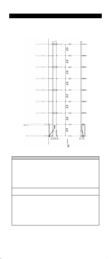
KNOW YOUR ET-PLUS™ SYSTEMS
For specific installation, maintenance, or repair details,
refer to the state/specifying agency’s standard drawing(s).
ET- PLUS™ (TL-3)
50' (15.24 m) SYSTEM
(This drawing represents one (1) version of the 50' (15.24 m) systems)
At post locations 1 and 2, the alternates to long foundation tube without soil plate
are:
• Hinged Breakaway™ (“HBA™”) post
• Short tube with soil plate
• HBA™ post at location 1, Steel Yielding Terminal Post™
• Long foundation at location 1, SYTP™ at location 2
• Short foundation with soil plate at location 1, SYTP™ at
The alternate to two (2) 12' 6" (3.81 m) long rail elements is one (1)
25’ 0” (7.62 m) long rail element.
For post locations 3 through 8 (50’ (15.24 m) system), alternates
are:
• All short tubes without soil plates and breakaway wood
• All HBA™ posts
• All CRT posts
• All SYTP™
• Any combination of above options, as accepted by the
www.highwayguardrail.com 5 Revised: October 5, 2009
Alternates for Foundation Tubes
(“SYTP™”) at location 2
location 2
posts
FHWA and dictated by the state/specifying agency
Revised: March 2010
Page 7
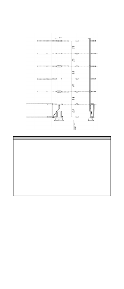
For specific installation, maintenance, or repair details,
refer to the state/specifying agency’s standard drawing(s).
ET-PLUS™ (TL-3)
37’ 6" (11.43 m) SYSTEM
(This drawing represents one (1) version of the 37' 6” (11.43 m) systems)
At post locations 1 and 2, the alternates to long foundation tube
without soil plate are:
For post locations 3 through 7 (37’ 6” (11.43 m) system),
alternates are:
Alternates for Foundation Tubes and Posts
• HBA™ post
• HBA™ post at location 1 and SYTP™ at location 2
• Long foundation tube or short tube with soil plate at
location 1 and SYTP™ at location 2
• All short tubes without soil plates and breakaway wood
posts
• All HBA™ posts (HBA™ post required at location 8)
• All CRT posts
• All SYTP™ (SYTP™ required for location 8)
• Any combination of above options, as accepted by the
FHWA and dictated by the state/specifying agency
www.highwayguardrail.com 6 Revised: October 5, 2009
Revised: March 2010
Page 8
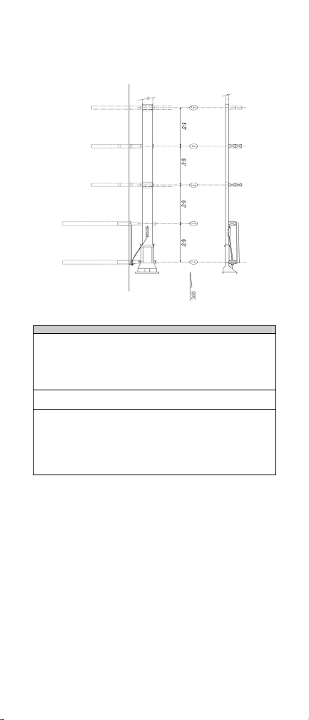
For specific installation, maintenance, or repair details,
refer to the state/specifying agency’s standard drawing(s).
ET-PLUS™ (TL-2)
25' (7.62 m) SYSTEM
(This drawing represents one (1) version of the 25' (7.62 m) systems)
Alternates for Foundation Tubes, Rail Panels, and Posts
At post locations 1 and 2, the alternates to long foundation tube
without soil plate are:
• HBA™ post
• HBA™ post at location 1 and SYTP™ at location 2
• Long foundation tube or short tube with soil plate at
location 1 and SYTP™ at location 2
The alternate to two (2) 12' 6" (3.81 m) long rail elements is one (1)
25’ 0” (7.62 m) long rail element.
For post locations 3 through 4 (25’ (7.62 m) system), alternates
are:
• Short steel foundation tubes without soil plates and
breakaway wood posts or SYTP™ in tubes
• All HBA™ posts
• All CRT posts
• All SYTP™
www.highwayguardrail.com 7 Revised: October 5, 2009
Revised: March 2010
Page 9
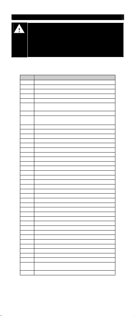
BILL OF MATERIAL ENGLISH (METRIC)
WARNING: Use only Trinity Highway Products’ parts on the ET-
PLUS™ systems for installation, maintenance, or repair. The
installation or co-mingling of unauthorized parts is strictly
prohibited. Failure to follow this warning could result in serious
injury or death in the event of a vehicle impact with a system that
has not been accepted by the Federal Highway Administration
(“FHWA”). The ET-PLUS™ systems and its component parts have
been accepted for state use by FHWA. However, a co-mingled
system has not been accepted.
(For specific materials and quantities, see state/specifying agency’s option(s))
PN Description
9G
32G
60G
62G
704A
705G
740G*
749G
766G*
782G
995A
3000G
3300G
3340G
3360G
3478G
3497G
3500G
3580G
3701G
3704G
3717G
3718G
3900G
3910G
4063B
4075B
4076B
4147B
4254G
4255G
4258G
4261G
4228B
4388G
4389G
4390G
4393G
5148G
4699G
ET-PLUS™ SYSTEMS
12/12.5'/6’ 3"/S (2.67/3.81/1.905/S) (Guardrail)
12/12.5"/6' 3"/S (2.67/3.81/1.905/S) ANC (Guardrail)
12/25'/6' 3"/S (2.67/7.62/1.905/S) (Guardrail)
12/25'/6' 3"/S (2.67/7.62/1.905/S) ANC (Guardrail)
Cable Anchor Bracket
Pipe Sleeve - 2" STD Pipe x 5
Pipe)
6" x 8" x 4' 6" x
6" x 8" x 6' 0" x
Sleeve (Alternate to using 740G and 766G)
18" x 24" x
5
8" x 8" x
/8” (200 x 200 x 16) Bearing Plate
ET-PLUS™ Extruder (Head)
Cable (Assembly)
5
/8" (16) Round Washer
5
/8" (16) HGR Nut
5
/8" DIA. X 11/4" (16 DIA. x 35) Splice Bolt (HGR)
5
/8" DIA. x 71/2" (16 DIA. x 190) Hex Head Bolt
5
/8" DIA. x 91/2" (16 DIA. x 240) Hex Head Bolt
5
/8" DIA. x 10" (16 DIA. x 255) HGR Post Bolt
5
/8" DIA. x 18" (16 DIA. x 460) HGR Post Bolt
3
/4" (19) Washer
3
/4” (19) HEX Nut
3
/4 “ x 21/2" (19 x 75) Hex Head Bolt (High Strength)
3
/4" x 3” (19 x 75) Hex Head Bolt (High Strength)
1" (25) Round Washer
1" (25) Hex Nut
Wood Post 6" x 8" x 6' 0" (150 x 200 x 1830) CRT
Wood Block 6" x 8" x 14" (150 x 200 x 360) DR
Wood Block - 6” x 8” x 14” (150 x 200 x 360) DR
Wood Post - 5
3
/8” (10) Round Washer
3
/8” (10) Fender Washer 11/2” OD (38)
3
/8” (10) Lockwasher
3
/8” DIA. X 11/2" (10 x 38) Hex Head Bolt
3
/8” x 4" (10 x 100) Lag Screw
7
/16” (11) Hex Nut
7
/16” (11) Round Washer
7
/16” DIA. x 11/2” (11 x 38) GR. 5 Hex Head Bolt
7
/16” (11) Lockwasher
3
/4” DIA. X 91/2” (19 DIA. x 240) Hex Head Bolt (High
Strength)
3
/4” (19) Lockwasher
1
/2" (50 STD Pipe x 150
3
/16 (152 x 203 x 1375 x 4.8) Tube Sleeve
3
/16 (152 x 203 x 1830 x 4.8 Tube
1
/4" (460 x 610 x 16) Soil Plate
3
/4" x 6' 6" (19 x 1981)
1
/2” x 71/2” x 3’ 9" (140 x 190 x 1145)
www.highwayguardrail.com 8 Revised: October 5, 2009
Revised: March 2010
Page 10

PN Description
3
6321G
/8” x 2’ (10 x 50) Hex Head Bolt (High Strength)
3
6405G
/8” (10) Hex Nut
6907B
Polymer Block 4” x 7
Block]
14329G#
14578G#
33871A#
33873A#
33874A#
33877A#
33875G#
33795G
33730G#
33847G#
* Option to the 6’0” Post Sleeve Tube
#
5
/8” SYTP Stub
3’ 6
6’ Steel Yielding Terminal Post (SYTP)
ET HBA Post #1 Top
ET HBA Post #1 and #2 Bottom
ET HBA Post #3 - #8 Bottom
ET HBA Post #2 - #8 Top
9852A#
Strut (and Yoke Assembly)
6' 6" (1980) Angle Strut ET HBA
#
6’ 6” (1980) Angle Strut
1
/2” (1980) Angle Strut
6’ 7
1
/8” Angle Strut
6’ 9
Review the state/specifying agency’s standard drawings of these
systems, for details that are specific to the project or site locations.
1
/2” x 14” (100 x 187 x 350) [King
Delineation Options
PN Description
6206B
6207B
6668B
Right Side 13” x 27
Left Side 13” x 27
Either Side 12” x 12” (305 x 305) Reflective Sheeting
(Typically 2 required)
1
/2” (325 x 700) Reflective Sheeting
1
/2” (325 x 700) Reflective Sheeting
www.highwayguardrail.com 9 Revised: October 5, 2009
Revised: March 2010
Page 11

INSTALLING THE ET-PLUS™ SYSTEMS
Use Trinity Highway Products’ drawings for the ET-PLUS™ systems with
these instructions. Review the state/specifying agency’s standard
drawings of this system. Details will be specific to the project or site
locations.
WARNING: Use only Trinity Highway Products’ parts on the ETPLUS™ systems for installation, maintenance, or repair. The
installation or co-mingling of unauthorized parts is strictly
prohibited. Failure to follow this warning could result in serious
injury or death in the event of a vehicle impact with a system that
has not been accepted by the Federal Highway Administration
(“FHWA”). The ET-PLUS™ systems and its component parts have
been accepted for state use by FHWA. However, a co-mingled
system has not been accepted.
WARNING: Ensure that there is proper site grading for tube and
post placement, as dictated by the state/specifying agency,
pursuant to FHWA acceptance. Failure to follow this warning
could result in serious injury or death in the event of a collision.
WARNING: Ensure that the proper Leaveout (specified area of
open space in the pavement) around the posts is reserved and
filled with state/specifying agency approved backfill material that
will not prevent movement, for any posts installed in rigid
pavement such as any thickness of concrete or asphalt. Failure to
follow this warning could result in serious injury or death in the
event of a collision.
WARNING: Do NOT install 6’0” CRT post at location 1. Failure to
follow this warning could result in serious injury or death in the
event of a collision.
WARNING: Do NOT install SYTP™ at location 1. Failure to
follow this warning could result in serious injury or death in the
event of a collision.
WARNING: Ensure that all Guardrail products and delineation
used meet all federal, state/specifying agency, and local
specifications. Failure to follow this warning could result in serious
injury or death in the event of a collision.
MATERIALS
As packaged, the ET-PLUS™ systems include all materials needed for a
complete installation. This will include either a 50’ (15.24 m) system, 37’
6” (11.43 m) system, or 25’ (7.62 m) system pay limit, unless otherwise
specified in the contract plans. Note that concrete footings or foundations
are not required.
TOOLS REQUIRED
The following list shows recommended tools for installation of the ETPLUS™ systems:
• 9/16” (14 mm) Socket or Wrench
•
• 1
• 1
• Augers
• Post Pounders (commonly used in driving posts)
• Locking Pliers
• Tape Measure
The following list shows recommended tools for the repair of the ETPLUS™ systems. However, since repair is directed by the
state/specifying agency, they may have more specific guidelines.
• Acetylene torch to cut off extruded rail
• Heavy-duty chain to remove the ET-PLUS™ Extruder (Head)
• Locking Pliers or channel lock pliers
• Sledge hammer
• Post removal tool and other normal guardrail tools
• Eye bolts connected to heavy duty chain (to remove the posts
• Vehicle to pull the Extruder from the damaged rail
15
/16” (24 mm) Socket or Wrench
1
/4” (32 mm) Socket or Wrench
1
/2” (38 mm) Socket or Wrench
from tubes)
www.highwayguardrail.com 10 Revised: October 5, 2009
Revised: March 2010
Page 12
SITE PREPARATION
When the Guardrail is installed in-line with edge of the shoulder (without
any offset), a 25:1 or flatter straight flare over the length of the systems
can be used to position the ET-PLUS™ Extruder (Head) further away
from the edge of the shoulder. Minor site grading may be necessary for
installations beyond the edge of the shoulder, for the proper placement of
the steel tubes and the CRT posts. Use the state/specifying agency’s
standard specifications and drawings for the site grading. Trinity does not
direct grading. Complete all grading before the start of the installation of
the ET-PLUS™ systems. See INSTALLATION OF THE ET-PLUS™
SYSTEMS ON A CURVE section for the layout of the ET-PLUS™
systems on a curve.
WARNING: Ensure that there is proper site grading for tube and
post placement, as dictated by the state/specifying agency,
pursuant to FHWA acceptance. Failure to follow this warning
could result in serious injury or death in the event of a collision.
INSTALLATION
WARNING: Ensure that this installation conforms with the
guidance provided by the AASHTO Roadside Design Guide,
including, but not limited to, those regarding placement on curbs.
Failure to follow this warning could result in serious injury or death
in the event of a collision.
For installation of the ET-PLUS™ systems, see POST INSTALLATION
section. If the systems are installed on a curve, see INSTALLATION OF
THE ET-PLUS™ SYSTEMS ON A CURVE. When installing the ETPLUS™
systems outside or inside the curve, the ET must be straight over
the length of the systems. If there are special field conditions
encountered when installing the ET-PLUS™ systems, contact the
state/specifying agency’s engineer. Trinity Highway Products LLC., at 1800-644-7976, is available to assist the state/specifying agency, if
needed.
POST INSTALLED IN RIGID MATERIAL
Provide the proper leave out (specified area of open space in the
pavement)
around a post when installing the post in any thickness of
concrete or asphalt.
placed in the rigid material “leave out” MUST be low enough so that
it does not engage the anchor cable bearing plate at Post 1 or
otherwise obstruct/constrain the
bolts of the HBA Post.
For "leave-out" information, please consult the applicable state/specifying
agency. Additional source of "leave-out" information/details can be found
in the U.S. Department of Transportation, Federal Highway
Administration, Memorandum B64-B, dated 3-10-04. Trinity can provide
this FHWA memo upon request.
INSTALLATION OF THE ET-PLUS™ SYSTEMS ON A
CURVE
When the ET-PLUS™ systems are installed on a curve, use the following
layouts. All offsets are measured to the face of the rail. Under no
circumstances shall the guardrail within the ET-PLUS™ pay limit be
curved.
Outside the curve: With the line guardrail installed parallel to the
curve, the terminal end is offset from the curve a distance equal to
the line guardrail offset plus the value in Table 1. (See
state/specifying agency drawings for details.)
• Inside the curve (radius Greater than 1000 feet): With the line
guardrail installed parallel to the curve, the terminal end is offset from
the curve a distance equal to the line guardrail offset plus the value
in Table 1. (See state/specifying agency drawings for details.)
• Inside the curve (radius 1000 feet or Less): With the line guardrail
installed parallel to the curve, the terminal end is offset from the
The top surfaces of any grout or other backfill
WARNING: Ensure that the proper Leaveout (specified area of
open space in the pavement) around the posts is reserved and
filled with state/specifying agency approved backfill material that
will not prevent movement, for any posts installed in rigid
pavement such as any thickness of concrete or asphalt.
www.highwayguardrail.com 11 Revised: October 5, 2009
3
/8” shear bolts or the ¾” hinge
Revised: March 2010
Page 13
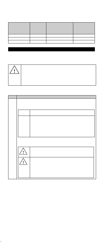
curve a distance equal to the line guardrail offset plus 1 foot
maximum in Table 1. (See state/specifying agency drawings for
details.)
ET™ Length Outside the
50 Feet
37 Feet 6 Inches
25 Feet
POST INSTALLATION
Complete the following steps when installing wood CRT posts, foundation
tubes with wood posts, HBA™ posts, and SYTP™. When installing posts
in rigid pavement, see the POST INSTALLED IN RIGID MATERIAL
section.
INSTALLING THE WOOD CRT POSTS
Complete the following steps to install the wood CRT posts:
Step Actions
1.
Curve Max
Offset
2 Feet 2 Feet 1 Foot
1.5 Feet 1.5 Feet 1 Foot
1 Foot 1 Foot 1 Foot
WARNING: Ensure that the proper Leaveout (specified area of
open space in the pavement) around the posts is reserved and
filled with state/specifying agency approved backfill material that will
not prevent movement, for any posts installed in rigid pavement
such as any thickness of concrete or asphalt. Failure to follow this
warning could result in serious injury or death in the event of a
collision.
Install the wood posts (PN-4063B) at locations required for the
systems, spaced at 6' 3" (1270 mm) apart. Select Option A or
Option B to install the CRT posts.
Option
Drive posts into the ground.
A
Option
1. Drill 12” (300 mm) maximum diameter pilot
B
2. Insert the 6' 0" (1830 mm) wood posts into these
3. Backfill the holes with compactable materials in
Note: In either option within Step 1, the bottom of the upper 31/2"
(90 mm) hole in the post is approximately at the finished grade.
WARNING: Do NOT install 6’0” CRT post at location 1.
Failure to follow this warning could result in serious injury
or death in the event of a collision.
WARNING: Ensure that the proper Leaveout (specified
area of open space in the pavement) around the posts is
reserved and filled with state/specifying agency approved
backfill material that will not prevent movement, for any
posts installed in rigid pavement such as any thickness of
concrete or asphalt. Failure to follow this warning could
result in serious injury or death in the event of a collision.
Inside the Curve
With a Radius
Greater Than 1000
Feet Max Offset
Table 1
Inside the Curve
With a Radius
1000 Feet or
Less Max Offset
holes approximately 44" (1120 mm) deep.
holes.
6" (150 mm) lifts and compact with pneumatic
equipment to optimum compaction.
www.highwayguardrail.com 12 Revised: October 5, 2009
Revised: March 2010
Page 14
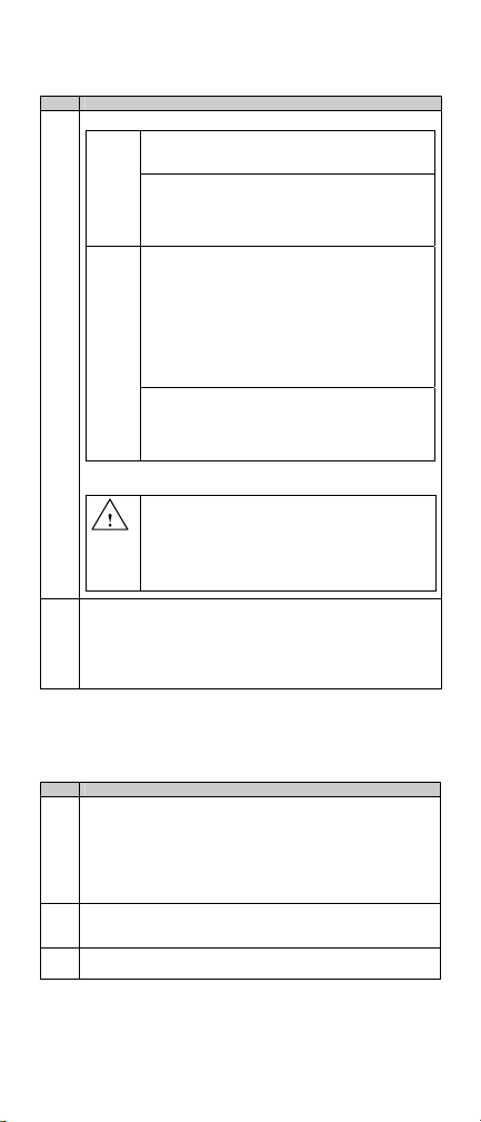
PLACING FOUNDATION TUBES FOR WOOD OR SYT™ POSTS
Complete the following steps to install foundation tubes and Wood or
SYT™ posts:
Step Actions
Select Option A or Option B for this tube installation.
1.
1. For 6' 0" (1830 mm) Tube without Soil Plate
Option
1. Install the foundation tube (PN-749G), per
A
Option
B
Note: Do not over tighten the nuts and deform the tubes, this will
complicate post replacement.
Install the foundation tubes at locations 1 and 2. Use the strut
2.
as a guide for the spacing of the tubes. If the soil plate is
utilized, position it on the downstream side of the post (away
from the impact head).
Note: Do not drive tubes with the wood post inserted, this will
complicate post replacement.
INSTALLATION OPTIONS FOR FOUNDATION TUBES FOR
WOOD OR SYT™ POSTS
Complete the following steps to install foundation tubes and Wood or
SYT™ posts:
FOR PERMEABLE SOIL
Step Actions
If the soil is permeable (water will drain from the tubes), drive
1.
the tubes (with an appropriate driving head) to the optimum
height, where the top of the tube is 2
finished grade.
Note: Take extra care to prevent settlement or lateral
displacement of the tubes, to ensure the posts attach to the
Guardrail, correctly.
Ensure that the finished Guardrail height will be approximately
2.
3
27
/4" (706 mm) above the finished grade, or as the state/
specifying agency plans indicate.
Ensure that the tubes do not project more than 4" (100 mm)
3.
above the finished grade.
Step 2 below.
2. For 4’ 6” (1375 mm) Tube without Soil Plate
(locations 3 through 8, locations 3 through 7,
or locations 3 through 4)
1. Install the soil tube (PN-740G), per Step 2
below.
1. For 4' 6" (1375 mm) Tube with Soil Plate
(locations 1 & 2)
1. Assemble the soil tubes and soil plates.
2. Bolt the soil plate (PN-766G) to the
foundation tube (PN-740G) with two
1
7
/2" (16 mm x 190 mm) Hex Head Bolts
(PN-3478G) and
(PN-3340G) (no washers).
3. Install the foundation tube (PN-766G) with
soil plate, per Step 2 below.
2. For 4’ 6” (1375 mm) Tube without Soil Plate
(locations 3 through 8, locations 3 through 7, or
locations 3 through 4)
1. Install the soil tube (PN-740G), per Step 2
below.
WARNING: Ensure that the proper Leaveout (specified
area of open space in the pavement) around the posts is
reserved and filled with state/specifying agency approved
backfill material that will not prevent movement, for any
posts installed in rigid pavement such as any thickness of
concrete or asphalt. Failure to follow this warning could
result in serious injury or death in the event of a collision.
5
/8" (16 mm) HGR Nuts
5
/8” (67 mm) above the
5
/8" x
www.highwayguardrail.com 13 Revised: October 5, 2009
Revised: March 2010
Page 15
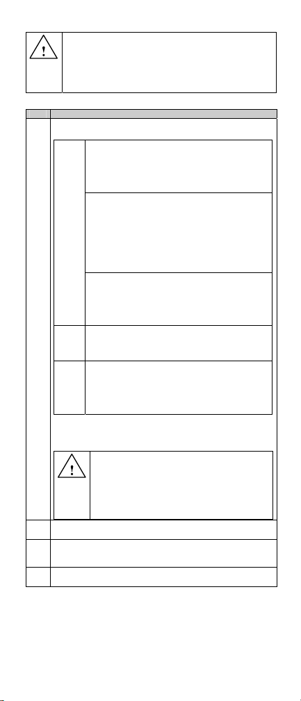
WARNING: Ensure that the proper Leaveout (specified area of
open space in the pavement) around the posts is reserved and
filled with state/specifying agency approved backfill material that
will not prevent movement, for any posts installed in rigid
pavement such as any thickness of concrete or asphalt. Failure to
follow this warning could result in serious injury or death in the
event of a collision.
FOR NON-PERMEABLE SOIL
Step Actions
Select Option A, Option B, or Option C below, if soil is non-
1.
permeable.
Option
For 6’ Tube Only
A
1. Drill a 12” (300 mm) maximum diameter pilot
hole approximately 75” (1905 mm) deep.
2. Insert the tube into the hole to the optimum
depth, where the top of the tube is 2
above the finished grade.
For 4’ 6” Tube with Soil Plate
1. Drill a 12” (300 mm) maximum diameter pilot
hole approximately 57” (1450 mm) deep.
2. Insert the soil plate/tube assembly into the hole
by impact or vibratory means with an
appropriate driving head.
3. Insert the tube to the optimum depth of where
the top of the tube is 2
the finished grade.
For 4’ 6” Tube without Soil Plate
1. Drill a 12” (300 mm) maximum diameter pilot
hole approximately 57” (1450 mm) deep.
2. Insert the tube into the hole to the optimum
depth, where the top of the tube is 2
Option
Option
Note: Take extra care to prevent settlement or lateral
displacement of the tubes, to ensure the posts attach to the
Guardrail, correctly.
Backfill the hole with compactable materials in 6" (150 mm) lifts
2.
and compact with pneumatic equipment to optimum compaction.
Ensure that the finished Guardrail height will be approximately
3.
27
state/specifying agency plans indicate.
Ensure that the tubes do not project more than 4" (100 mm)
4.
above the finished grade.
above the finished grade.
For 4’ 6” Tube with Soil Plate
B
Cut slots for the soil plates out by hand or by using a
rock bar and then follow all of the steps of Option A
for 4’ 6” tube with soil plate, above.
For 4’ 6” Tube with Soil Plate
C
Drill three adjacent 12” (300 mm) maximum
diameter holes or one 24” (610 mm) maximum
diameter hole to accommodate the soil plate/tube
assembly and then follow all of the steps of Option A
for 4’ 6” tube with soil plate, above.
WARNING: Ensure that the proper Leaveout (specified
area of open space in the pavement) around the posts is
reserved and filled with state/specifying agency
approved backfill material that will not prevent
movement, for any posts installed in rigid pavement
such as any thickness of concrete or asphalt. Failure to
follow this warning could result in serious injury or death
in the event of a collision.
3
/4" (706 mm) above the finished grade, or as the
5
/8" (67 mm) of the above
5
/8” (67 mm)
5
/8” (67 mm)
www.highwayguardrail.com 14 Revised: October 5, 2009
Revised: March 2010
Page 16
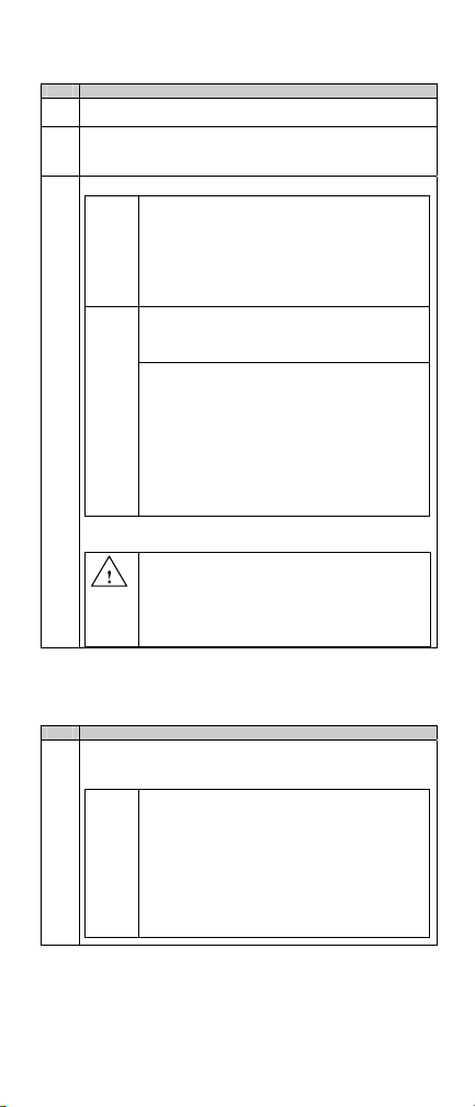
INSTALLING HBA™ BOTTOM POSTS
Complete the following steps to install HBA™ Bottom Posts:
Step Actions
Arrange the posts so that the large hole (
1.
downstream (away from the impact end of the systems).
Adjust the offset to Post 2, if the ET-PLUS™ Extruder (Head)
2.
causes a gap between the rail panel and Post 2.
Note: The rail panel must be within 1/2” (13 mm) of Post 2.
Select Option A or Option B for this installation.
3.
Option
Option
Note: In either option, the optimum depth will have the 13/16” (21
mm) hole in the post plates (ears) even with the finished grade.
INSTALLING FOUNDATION TUBES, HBA™ POSTS, OR SYTP™
WHEN ENCOUNTERING ROCK
Complete the following steps to install foundation tubes, HBA™ posts or
SYTP™ when encountering rock:
Step Actions
Select Option A or Option B below when encountering rock,
1.
unless there is a more restrictive state/specifying agency
specification.
Option
1. Drive the HBA™ Bottom Posts (PN-33873A,
A
B
A
PN-33874A) with an approved driving head
to the appropriate depths. The appropriate
depth will be approximately 72” (1830 mm)
for post PN-33873A, at Posts 1 and 2 and
44” (1120 mm) for post PN-33874A, at Posts
3 through 8, Posts 3 through 7, or Posts 3
through 4.
For HBA™ Bottom Posts (PN-33873A) at Posts 1
and 2
1. Drill a 12” (300 mm) maximum diameter pilot
hole approximately 72” (1830 mm) deep.
For HBA™ Bottom Posts (PN-33874A) at Posts 3
through 8, Posts 3 through 7, or Posts 3 through
4
1. Drill a 12” (300 mm) maximum diameter pilot
hole approximately 44” (1120 mm) deep.
2. Insert the posts to the appropriate depth by
impact or vibratory means with an appropriate
driving head.
3. Backfill the hole with compactable materials in 6"
(150 mm) lifts and compact with pneumatic
equipment to optimum compaction.
WARNING: Ensure that the proper Leaveout (specified
area of open space in the pavement) around the posts is
reserved and filled with state/specifying agency approved
backfill material that will not prevent movement, for any
posts installed in rigid pavement such as any thickness of
concrete or asphalt. Failure to follow this warning could
result in serious injury or death in the event of a collision.
If rock is encountered with depth of 20" (510
mm) or less
1. Drill a 12" - 16" (300 mm - 400 mm) diameter
hole into the rock.
2. Drill the hole 2" (50 mm) deeper than the
required embedment depth.
3. Place granular material or small pieces of the
drilled rock in the bottom 2" (50 mm) of the hole
for drainage.
Continues on next page.
13
/16” [21 mm]) is placed
www.highwayguardrail.com 15 Revised: October 5, 2009
Revised: March 2010
Page 17
INSTALLING WOOD POSTS IN TUBES
Complete the following steps to install wood posts in tubes:
Step Actions
1.
2.
3.
4.
5.
INSTALLING HBA™ TOP POSTS
Complete the following steps to install the HBA™ Top Posts, after the
Bottom Posts have been installed:
AT POST 1
Step Actions
1.
2.
4. Install the tube/post into the hole. Backfill the
hole with compactable materials in 6" (150 mm)
lifts and compact with pneumatic equipment to
optimum compaction.
Note: If compactable, the material removed from
the hole may be used for the backfill.
Option
If rock is encountered with depth greater than
B
20" (510 mm)
1. Drill a 12" - 16" (300 mm - 400 mm) diameter
Insert Pipe Sleeve (PN-705G) in post (PN-4147B) and install the
wood post in the steel tube at location 1.
Install wood post(s) (PN-4147B) in tubes at locations required
for the systems, as dictated by the state/specifying agency.
Insert a
3497G) through the foundation tube and the wood post at all
locations EXCEPT locations 1 and 2.
Note: The bolt must be installed from the embankment side, to
aid in possible post replacement.
Place a
inserted bolt.
Tighten the nuts to a snug position.
Note: Do not over tighten the bolts and deform the tubes, this
will complicate post replacement.
Install the Top Post (PN-33871A) at Post 1, by aligning the
holes of the post plates (ears) on the Top and Bottom Posts.
Note: The Top Post’s post plates (ears) can be installed on
either side of the Bottom Post’s post plates (ears).
Insert a
Strength Bolt (PN-6321G) through the
www.highwayguardrail.com 16 Revised: October 5, 2009
hole 22" (560 mm) deep into the rock.
2. Cut off the embedded portion of the tube/post so
the Guardrail will be installed at the proper
mounting height.
3. Place granular material or small pieces of the
drilled rock in the bottom 2" (50 mm) of the hole
for drainage.
4. Install the tube/post in the hole. Backfill the hole
with compactable materials in 6" (150 mm) lifts
and compact with pneumatic equipment to
optimum compaction.
Note: If compactable, the material removed from
the hole may be used for the backfill.
WARNING: Ensure that the proper Leaveout (specified
area of open space in the pavement) around the posts is
reserved and filled with state/specifying agency approved
backfill material that will not prevent movement, for any
posts installed in rigid pavement such as any thickness of
concrete or asphalt. Failure to follow this warning could
result in serious injury or death in the event of a collision.
5
/8” x 91/2” (16 mm x 240 mm) Hex Head Bolt (PN-
5
/8” (16 mm) HGR Nut (PN-3340G) on the end of the
WARNING: Ensure that the proper Leaveout (specified area of
open space in the pavement) around the posts is reserved and
filled with state/specifying agency approved backfill material that
will not prevent movement, for any posts installed in rigid
pavement such as any thickness of concrete or asphalt. Failure to
follow this warning could result in serious injury or death in the
event of a collision.
3
/8” (10 mm) diameter x 2” (50 mm) Hex Head High
7
/16” (11 mm) holes of the
Revised: March 2010
Page 18

post plates (ears) on the Top and Bottom Posts.
3.
4.
5.
6.
7.
AT POST 2
Step Actions
1.
2.
3.
4.
5.
6.
7.
AT POSTS 3 THROUGH 8, POSTS 3 THROUGH 7, OR POSTS 3 AND
4
Step Actions
1.
2.
3.
4.
3
Place a
/8” (10 mm) Washer (PN-4252G) and a 3/8” (10 mm)
Lockwasher (PN-4258G) under a
6405G) on the inserted bolts to secure.
Note: The bolts can be installed so the nuts are on the inside or
outside of the post plates (ears).
Tighten the nuts to a snug position. The designer does not
recommend a torque requirement for the HBA field assembly
3
Insert a
/4” (19 mm) diameter x 21/2” (63 mm) Hex Head High
Strength Bolt (PN-5148G) in the
HBA™ Post 1 post plates on the side opposite the strut.
Do not install the 3/4” (19 mm) bolt on the strut side of Post 1,
until the strut is ready to be installed.
Note: The bolts can be installed so the nuts are on the inside or
outside of the post plates (ears).
3
Place a
/4” (19 mm) Washer (PN-3701G) and a 3/4” (19 mm)
Lockwasher (PN-4699G) under a
inserted bolt to secure.
Tighten the nuts to a snug position. The designer does not
recommend a torque requirement for the HBA field assembly
Install the Top Post (PN-33877A) at Post 2, by aligning the
holes of the post plates (ears) on the Top and Bottom Posts.
3
Insert a
/8” (10 mm) diameter x 2” (50 mm) Hex Head High
Strength Bolt (PN-6321G) in the
Note: For the bolt opposite the strut, install it so the nut is on
either side of the post plates (ears). For the
is on the side of the strut, install the bolt through the post plates
(ears) with the bolt head on the same side as the strut.
3
Place a
/8” (10 mm) Washer (PN-4251G) and a 3/8” (10 mm)
Lockwasher (PN-4258G) under a
6405G) on the inserted bolts to secure.
Tighten the nuts to a snug position. The designer does not
recommend a torque requirement for the HBA field assembly
3
Insert a
/4” (19 mm) diameter x 2 ½” (63 mm) Hex Head High
Strength Bolt (PN-5148G) through the
HBA™ Post 2 post plates on the side opposite the strut.
Do not install the 3/4” (19 mm) bolt on the strut side of Post 2,
until the strut is ready to be installed.
Note: The bolts can be installed so the nuts are on the inside or
outside of the post plates (ears).
3
Place a
/4” (19 mm) Washer (PN-3701G) and a 3/4” (19 mm)
Lockwasher (PN-4699G) under a
inserted bolt to secure.
Tighten the nuts to a snug position. The designer does not
recommend a torque requirement for the HBA field assembly
Arrange the Top Posts (PN-33877A), for Posts 3 through 8,
Posts 3 through 7, or for Posts 3 through 4, by aligning the
holes of the post plates (ears) on the HBA™ Top and Bottom
Posts, if used.
3
Insert a
/8” (10 mm) diameter x 2” (50 mm) Hex Head Bolt (PN6321G) through in the
(ears).
3
Place a
/8” (10 mm) washer (PN-4254G) and a 3/8” (10 mm)
Lockwasher (PN-4258G) under a
6405G) on the inserted
3
Insert a
/4” (19 mm) diameter x 21/2” (63 mm) Hex Head High
Strength Bolt (PN-6321G) through the
Note: The bolts can be installed so the nuts are on either side of
the post plates (ears).
www.highwayguardrail.com 17 Revised: October 5, 2009
3
/8” (10 mm) Hex Nut (PN-
13
/16” (21 mm) hole of the
3
/4” (19 mm) Hex Nut on the
7
/16” (11 mm) holes.
3
/8” (10 mm) bolt that
3
/8” (10 mm) Hex Nut (PN-
13
/16” (21 mm) hole of the
3
/4” (19 mm) Hex Nut on the
7
/16” (11 mm) holes of the post plates
3
/8” (10 mm) Hex Nut (PN-
3
/8” diameter Hex Head Bolt.
13
/16” (21 mm) holes.
Revised: March 2010
.
.
.
.
Page 19
Place a 3/4” (19 mm) Washer (PN-4252G) and a 3/4” (19 mm)
5.
Lockwasher (PN-4258G) under
3
inserted
/4” (19 mm) diameter Hex Head High Strength Bolt to
secure.
Tighten the nuts to a snug position. The designer does not
6.
recommend a torque requirement for the HBA field assembly
INSTALLING THE SYTP™
The SYTP™ can be driven or installed in a tube. For SYTP™ installation
in a tube, see the INSTALLING THE SYTP™ IN TUBES section. The
SYTP™ can be installed at all locations EXCEPT at location 1.
Complete the following step to install the SYTP™:
WARNING: Do NOT install SYTP™ at location 1. Failure to
follow this warning could result in serious injury or death in the
event of a collision.
DRIVING THE 6’ SYTP™
Step Actions
Drive all the 6’0” SYTP™ (PN-14578) to the optimum depth,
1.
where the centers of the four (4) yielding holes through the
flange are at the ground line.
WARNING: Do NOT install SYTP™ at location 1.
Failure to follow this warning could result in serious injury
or death in the event of a collision.
WARNING: Ensure that the proper Leaveout (specified
area of open space in the pavement) around the posts is
reserved and filled with state/specifying agency approved
backfill material that will not prevent movement, for any
posts installed in rigid pavement such as any thickness of
concrete or asphalt. Failure to follow this warning could
result in serious injury or death in the event of a collision.
INSTALLING THE SYTP™ IN TUBES
Step Actions
Install the 3’ 6
1.
by the state/specifying agency.
Follow the instructions in the INSTALLING THE STRUT section,
2.
Step 5.
Except at Posts 1 and 2, install the SYTP™ in a tube at
3.
locations required for the systems with the four (4) yielding
holes (through the flange) at the top of the tube.
From the embankment side of the tube, insert a
4.
mm x 240 mm) Hex Head Bolt (PN-3497G) through the tube, the
Spacer (PN-4161), and the SYTP™.
Place a
5.
to secure the SYTP™ to the tube.
Note: Do not over tighten the nut and deform the tube, this will
complicate post replacement.
5
/8” SYTP(s) ™ (PN-14329) in tubes, as dictated
WARNING: Do NOT install SYTP™ at location 1.
Failure to follow this warning could result in serious injury
or death in the event of a collision.
WARNING: Ensure that the proper Leaveout (specified
area of open space in the pavement) around the posts is
reserved and filled with state/specifying agency approved
backfill material that will not prevent movement, for any
posts installed in rigid pavement such as any thickness of
concrete or asphalt. Failure to follow this warning could
result in serious injury or death in the event of a collision.
5
/8” (16 mm) HGR Nut (PN-3340G) on the inserted bolt,
3
/4” (19 mm) Hex Nut on the
5
/8” x 91/2” (16
.
www.highwayguardrail.com 18 Revised: October 5, 2009
Revised: March 2010
Page 20
INSTALLING THE STRUT
Complete the following steps when installing the strut:
Note: For All strut installations, the installer must provide a shallow
valley/trough for installation of the strut, since a portion of the angle
strut will be below grade.
INSTALLING THE STRUT WITH HBA™ POSTS/SYTP™
Complete the following steps to install the strut with HBA™
posts/SYTP™:
Step Actions
Place the Angle Strut (PN-33875G for HBA™, or PN-33795G for
1.
HBA™/SYTP™) on the outside flanges of the HBA™ posts or
the SYTP™ at locations 1 and 2. (Use PN-33875G with the
HBA™ posts or the HBA™ post/SYTP™ in a tube. Use PN33795G with the HBA™ post/SYTP™.)
Note: The strut can be placed with one of the legs flat on the
ground or with the leg edge on the ground. The strut may
be installed either on the traffic side or the field side of
the posts.
3
Install a
2.
3.
4.
5.
/4” (19 mm) diameter x 2 1/2” (63 mm) Hex Head High
Strength Bolt (PN-3717G) in the
HBA™ Post 1 post plates. Place the bolt through the top and
Bottom Post’s post plates and through the strut.
3
Place a
/4” (19 mm) Washer (PN-3700G) and a 3/4” (19 mm)
Lockwasher under a
to secure.
Tighten the nuts to a snug position.
recommend a torque requirement.)
Select Option A, Option B, or Option C below, for installing the
strut on post 2:
Option
For HBA™ post at location 2
A
1. Insert a
Option
Option
Head High Strength Bolt (PN-3718G) through the
strut, two or three ¾” (19 mm) Washers (PN3701G), and the
HBA™ post plates of Post 2. (The two or three
washers allow the strut to pass over the
mm) bolt head.)
2. Place a
Lockwasher (PN-4699G) under a
Hex Nut (PN-3704G) on the inserted bolt.
3. Tighten the nuts to a snug position. The designer
does not recommend a torque requirement for
the HBA field assembly.
For 6’ SYTP™ only at location 2
B
1. Place a
on the two (2)
mm) Hex Head High Strength Bolts (PN-4390G).
2. Place the bolts in the two slotted holes of the strut
and the yielding diameter holes of the SYTP™.
3. Place a Lockwasher (PN-4699G) under a
Hex Nut (PN-3704G) on the ends of the inserted
bolts.
4. Tighten the nuts to a snug position. (The designer
does not recommend a torque requirement.)
5
/8” SYTP™ in tube at location 2
For 3’ 6
C
1. Place a
diameter x 9
Strength Bolt (PN-3718G).
2. From the embankment side, insert the bolt
through the strut, foundation tube, Spacer (PN-
4161), and the SYTP™.
3. Place a washer under a nut on the end of the
inserted bolt.
4. Tighten the nuts to a snug position. (The designer
does not recommend a torque requirement.)
Note: Do not over tighten the bolts and deform the
tubes, this will complicate post replacement.
13
/16” (21 mm) hole of the
3
/4” (19 mm) Hex Nut on the end of the bolt
(The designer does not
3
/4” (19 mm) diameter x 3” (75 mm) Hex
13
/16” (21 mm) holes of the
3
/4” (19 mm) washer and a 3/4” (19 mm)
7
/16” (11 mm) Round Washer (PN-4389G)
7
/16” (11 mm) diameter x 11/2” (38
3
/4” (19 mm) Washer (PN-3701G) on
1
/2” (240 mm) Hex Head High
3
3
/4” (19 mm)
/8” (10
7
/16”
www.highwayguardrail.com 19 Revised: October 5, 2009
Revised: March 2010
Page 21
INSTALLING THE STRUT WITH WOOD CRT POST IN TUBE AT
POST 1 AND SYTP™/ SYTP™ IN TUBE AT POST 2
Complete the following steps to install the strut with wood post in soil tube
at Post 1 and SYTP™/ SYTP™ in tube at Post 2:
AT POST 1
Step Actions
Place the angle strut (PN-33795G) on the embankment side of
1.
the SYTP™. (The strut can be placed with one of the legs flat
on the ground or with the leg edge on the ground.)
7
Place a
2.
3.
4.
5.
FOR ANGLE STRUT WITH 6’ SYTP™ ONLY AT POST 2
Step Actions
1.
2.
3.
4.
5.
FOR ANGLE STRUT WITH SYTP™ IN TUBE AT POST 2
Step Actions
1.
2.
3.
4.
5.
INSTALLING THE STRUT WITH WOOD POSTS IN SOIL TUBE
Complete the following steps to install the strut with wood posts in soil
tubes:
Step Actions
1.
/16” (11 mm) Round Washer (PN-4389G) on the two (2)
7
/16” (11 mm) diameter x 11/2” (38 mm) Hex Head High Strength
Bolts (PN-4390G).
Insert the two bolts through the two slotted holes of the strut and
the yielding diameter holes of the SYTP™, at Post 2.
7
Place a
/16” (11 mm) Lockwasher (PN-4393G) under a 7/16” (11
mm) Hex Nut (PN-4388G) on the ends of the inserted bolts.
Tighten the nuts to a snug position.
recommend a torque requirement.)
Place the angle strut (PN-33795G) on the embankment side of
the SYTP™. (The strut can be placed with one of the legs flat
on the ground or with the leg edge on the ground.)
7
Place a
/16” (11 mm) Round Washer (PN-4389G) on the two (2)
7
/16” (11 mm) diameter x 11/2” (38 mm) Hex Head High Strength
Bolts (PN-4390G).
Insert the two bolts through the two slotted holes of the strut and
the yielding diameter holes of the SYTP™, at Post 2.
7
Place a
/16” (11 mm) Lockwasher (PN-4393G) under a 7/16” (11
mm) Hex Nut (PN-4388G) on the ends of the inserted bolts.
Tighten the nuts to a snug position.
recommend a torque requirement.)
Place the angle strut (PN-33795G) on the embankment side of
the tube. (The strut can be placed with one of the legs flat on
the ground or with the leg edge on the ground.)
3
Place a
/4” (19 mm) Washer (PN-3701G) on a 3/4” (19 mm)
1
diameter x 9
4699G).
From the embankment side, insert the bolt through the strut,
foundation tube, Spacer (PN-4161), and the SYTP™ at Post 2.
Place a
Hex Nut on the end of the inserted bolt.
Tighten the nuts to a snug position.
recommend a torque requirement.)
Note: Do not over tighten the bolts and deform the tubes, this
will complicate possible post replacement.
Select the Option A or Option B for installing the strut with wood
posts in soil tubes:
/2” (240 mm) Hex Head High Strength Bolt (PN-
3
/4” (19 mm) Washer (PN-3701G) under a 3/4” (19 mm)
Option
For angle strut
A
1. Place the angle strut (PN-33875G) on the
embankment side of the foundation tubes.
2. Place a
3
a
/4” (19 mm) diameter x 91/2” (240 mm) Hex
Head High Strength Bolt (PN-5148G).
(The designer does not
(The designer does not
(The designer does not
3
/4” (19 mm) Washer (PN-3701G) on
www.highwayguardrail.com 20 Revised: October 5, 2009
Revised: March 2010
Page 22
Option
Note: Do not over tighten the bolts and deform the tubes, this
will complicate possible post replacement.
INSTALLING OFFSET BLOCKS AND RAIL PANELS
The ET-PLUS™ systems use 25’ 0” (7.62 m) rail panels (PN-60G and/or
PN-62G) or 12’ 6” (3.81 m) rail panels (PN-9G and/or PN-32G). The
state/specifying agency standards must be reviewed for what systems to
use.
SPLICING THE RAIL PANELS
Complete the following steps to splice the rail panels:
Step Actions
Lap the terminal rail in the direction of traffic, unless the
1.
state/specifying agency’s policy dictates otherwise.
Splice the rail panels together with eight (8)
2.
32 mm), HGR Splice Bolts (PN-3360G), and
Hex Nuts.
Tighten the bolts. (There is no torque requirement.)
3.
3. From the embankment side, insert the bolt
through the strut, the foundation tube, and
the wood post.
4. Place a second washer under a
Hex Nut (PN-3704G) on the end of the
inserted bolt.
5. Tighten the nuts to a snug position.
designer does not recommend a torque
requirement.)
For channel ground strut
B
1. Place the slotted yokes of the ground strut
(PN-9852A) over the foundation tubes, at
the base of Posts 1 and 2.
5
2. Place a
3. From the embankment side, insert the bolt
4. Place a second washer under a
5. Tighten the nuts to a snug position.
/8" (16 mm) Round Washer (PN3300G) on a
(240 mm) Hex Head Bolt (PN-3497G).
through the strut, foundation tube, and the
wood post.
HGR Hex Nut on the end of the inserted
bolt.
designer does not recommend a torque
requirement.)
5
/8" (16 mm) diameter x 91/2"
3
/4” (19 mm)
(The
5
/8" (16 mm)
(The
WARNING: Do NOT bolt the rail panel to the post at location 1 in
any of the ET-PLUS™ systems. Failure to follow this warning
could result in serious injury or death in the event of a collision.
WARNING: Do NOT bolt the rail to the HBA™ post at location 2.
Failure to follow this warning could result in serious injury or death
in the event of a collision.
5
/8” x 11/4” (16 mm x
5
/8" (16 mm) HGR
www.highwayguardrail.com 21 Revised: October 5, 2009
Revised: March 2010
Page 23
INSTALLING THE OFFSET BLOCK AND RAIL PANEL TO
WOOD POSTS (POSTS 3 THROUGH 7 OR 8)
Complete the following steps to attach the offset blocks and rail panels to
the wood post:
Step Actions
At locations with wood posts and wood blocks, insert a
1.
mm) diameter x 18” (460 mm) HGR Post Bolt (PN-3580G)
through the rail panel, offset block (PN-4075B), and the post.
Note: Offset blocks are NOT used at post locations 1 and 2,
but are used at all other locations.
WARNING: Do NOT bolt the rail panel to the post at
location 1 in any of the ET-PLUS™ systems. Failure to
follow this warning could result in serious injury or death
in the event of a collision.
5
Place a
2.
3.
4.
INSTALLING THE OFFSET BLOCK AND RAIL PANEL TO
HBA™ POSTS OR SYTP™ (POSTS 3 THROUGH 7 OR 8)
Complete the following steps to attach the offset blocks and rail panels to
the HBA™ post or SYTP™:
Step Actions
1.
2.
3.
/8” (16 mm) Round Washer (PN-3300G) under a 5/8” (16
mm) HGR Nut (PN-3340G).
Tighten the bolts. (There is no torque requirement for these
bolts.)
Secure the offset block by toe nailing the block to the post or the
post to the block, with two (2) 16d hot-dipped galvanized nails
approximately 3” (75 mm) from the top of the post or block, one
on each side, to prevent it from rotating.
At locations with HBA Posts or SYTP™ with wood blocks, insert
5
a
/8” (16 mm) diameter x 10” (255 mm) HGR Post Bolt (PN-
3500G) through the rail panel, Routered Wood (PN-4076B) or
Composite Blockout, and the HBA™ post or SYTP™.
Note: Offset blocks are NOT used at post locations 1 and 2
For SYTP™ stubs, there are two (2) sets of holes in the SYTP™
for attaching the rail. Use the holes in the SYTP™ stub that will
place the rail at the correct height.
WARNING: Do NOT bolt the rail panel to the post at
location 1 in any of the ET-PLUS™ systems. Failure to
follow this warning could result in serious injury or death
in the event of a collision.
WARNING: Ensure all wood blocks or composite blocks
used with steel posts are routered. Failure to follow this
warning could result in serious injury or death in the
event of a collision.
5
Place a
/8” (16 mm) Round Washer (PN-3300G) under a 5/8” (16
mm) HGR Nut (PN-3340G) on the inserted bolt.
Tighten the bolts. (There is no torque requirement for these
bolts.)
5
/8” (16
www.highwayguardrail.com 22 Revised: October 5, 2009
Revised: March 2010
Page 24
INSTALLING THE RAIL PANEL TO THE POST WITHOUT OFFSET
BLOCK AT POST 2
Complete the following steps to attach the rail panel to the post without
offset block at Post 2:
Step Actions
Select the Option A, Option B, or Option C to install the rail
1.
panel without offset block at Post 2:
Option
Option
SYTP™
Option
INSTALLING THE CABLE ANCHOR ASSEMBLY
The Cable Anchor Bracket (PN-704A) is secured to the rail panel, by
inserting the square protruding hooks/lugs on the bracket into the square
slots in the rail panel. The Cable Anchor Bracket is locked into place, by
pulling the bracket towards the impact end of the unit, making sure the
hooks/lugs are well seated into the square holes.
Complete the following steps to install the cable anchor assembly:
Step Actions
Slide one end of the cable (PN-3000G) into the Cable Anchor
1.
Bracket and the other end through Post 1.
Place a 1" (25 mm) Washer (PN-3900G) and 1” (25 mm) Hex
2.
Nut (PN-3910G) on the end of the cable that extends through
the Cable Anchor Bracket. Turn the nut, until at least 2 threads
are completely through the nut.
Place the Bearing Plate (PN-782G) on the impact side of Post 1
3.
where the cable extends through the post. The cable bearing
plate MUST BE oriented with the “long” dimension turned
up. The hole in the bearing plate is off center (in the vertical
direction), 5” (125 mm) from one edge and 3” (75 mm) from
the opposite edge.
If applying the Bearing Plate (PN-782G) to a wood post at Post
4.
1, drive two nails along the top edge of the Bearing Plate and
bend over to prevent the Bearing Plate from rotating.
Place a 1” (25 mm) washer under a nut on the end of the cable
5.
extending through Post 1.
Restrain the cable with locking pliers at the end being tightened,
6.
to avoid twisting the cable.
Tighten the Hex Nuts on the cable ends, until the cable is taut.
7.
www.highwayguardrail.com 23 Revised: October 5, 2009
1. Insert a 5/8” (16 mm) diameter x 10” (255 mm)
A
HGR Post Bolt (PN-3500G) through the rail and
For
the wood post at location 2.
Wood
Post
B
For
C
For
HBA™
Post
5
2. Place a
1. Insert a 5/8” (16 mm) diameter x 11/4” (31 mm)
2. Place a 5/8” (16 mm) Round Washer (PN-3300G)
1. Do NOT bolt the rail panel to the HBA™ post at
WARNING: Any grout, backfill, or other materials (such
as concrete, asphalt, or soil) must be low enough so as
not to obstruct, constrain, or otherwise engage the
bearing plate. Failure to eliminate the interaction of soil or
materials with the bearing plate will hinder the
performance of the ET-PLUS™ systems and could result
in serious injury or death in the event of a collision.
/8” (16 mm) Round Washer (PN-
3300G) under a
3340G) on the inserted bolt. Tighten the bolts.
(There is no torque requirement for these bolts.)
HGR Blot (PN-3360G) through the rail panel and
the hole in the SYTP™.
Note: For SYTP stubs, use the hole in the
SYTP™ that will place the rail at the correct
height. (If there are two (2) sets of holes in the
SYTP™ stub for attaching the rail.)
under a
the inserted bolt.
5
/8” (16 mm) HGR Nut (PN-
5
/8” (16 mm) HGR Nut (PN- 3340G) on
location 2.
WARNING: Do NOT bolt the rail to the
HBA™ post at location 2. Failure to follow
this warning could result in serious injury or
death in the event of a collision.
Revised: March 2010
Page 25
The cable is considered taut, when it does not deflect more than
1 inch when pressure is applied by hand in an up or down
direction.
8. The shank portion of the anchor cable MUST BE positioned
so it bears on the bottom edge of the web of the HBA post.
The shank portion of the anchor cable must also be
centered horizontally so that the bearing plate bears
uniformly on both flanges of Post 1.
INSTALLING THE ET-PLUS™ EXTRUDER (HEAD)
Complete the following steps to install the ET-PLUS™ Extruder (Head):
Step Actions
Place the ET-PLUS™ Extruder (Head (PN-995A)) over the end
1.
of the rail panel as the final piece to attach to the assembly.
Note: The ET-PLUS™ Extruder (Head) can be used on the left
or right hand shoulder.
Push the ET-PLUS™ Extruder (Head) as far as it will go on the
2.
rail panel, making sure the rail is in the channel chute.
Install the ET-PLUS™ Extruder channel chute approximately
3.
parallel to the ground. The attachment brackets have 3 holes in
each bracket to provide tolerance in the installation.
Select the Option A or Option B for the ET-PLUS™ Extruder
4.
(Head) installation:
Option
For Wood post
A
1. Place the ET-PLUS™ Extruder (Head)
against the wood post, at location 1.
2. Choose the hole in the bracket that is
closest to the center of the post.
1
3. Drill a
/4” (6 mm) pilot hole to avoid breaking
the lag screw during installation.
4. Screw one (1)
(100 mm) Lag Screw (PN-4228B) in the top
and bottom bracket. The lag screw must be
screwed into the post to prevent it from
Option
B
DELINEATION OPTION FOR THE ET-PLUS™
Install high intensity reflective sheeting (PN-6206B [Right Side] or PN6207B [Left Side]) on the front face of the ET-PLUS™ Extruder (Head),
per the state/specifying agency’s MUTCD for options or proper
delineation. Alternate reflective sheeting is PN-6668B. The alternate
reflective sheeting requires two pieces and must be rotated for proper
delineation.
pulling out or cracking the post.
For HBA™ post
1. Place the ET-PLUS™ Extruder (Head)
against the HBA™ post, at location 1.
2. Place a
4254G) on a
(38 mm) Hex Head Bolt (PN-4261G).
3. Insert the bolt through the flange of the ETPLUS™ Extruder (Head) and the flange of
HBA™ post.
4. Place a
4255G) under a
6405G) on the end of the inserted bolt.
5. Tighten the nuts to a snug position. The
designer does not recommend a torque
requirement for the HBA field assembly.
3
/8” (10 mm) diameter x 4”
3
/8” (10 mm) Round Washer (PN-
3
/8” (10 mm) diameter x 11/2”
3
/8” (10 mm) Fender Washer (PN-
3
/8” (10 mm) Nut (PN-
Note: The reflective sheeting is an option to the ET-PLUS™ and needs to
be ordered separate from the ET-PLUS™ package.
WARNING: Ensure that your installation, repair, and maintenance
meet all appropriate Manual on Uniform Traffic Control Devices
(MUTCD) and local standards. Failure to follow this warning could
result in serious injury or death in the event of a collision.
www.highwayguardrail.com 24 Revised: October 5, 2009
Revised: March 2010
Page 26

INSTALLATION CHECKLIST
STATE: _____________PROJECT: ___________________________________
DATE: ______________LOCATION: __________________________________
The Leaveout (specified area of open space in the pavement) around the posts is
reserved and filled with state/specifying agency approved backfill material that will not
prevent movement, for any posts installed in rigid pavement such as any thickness of
concrete or asphalt.
The finished Guardrail height is approximately 27
the state/specifying agency plans indicate.
Any site grading needed was completed, before the start of the installation of the ET-
PLUS™ systems.
The steel tubes or post plates (ears) to the HBA™ Bottom Posts do not protrude more
than 4” (100 mm) above the finished grade measured by the American Association of
State Highway and Transportation Officials (“AASHTO”) 5’ (1.5 m) cord method. Site
grading may be necessary to meet this requirement.
3
The
/4” bolts connecting the tops of the HBA™ Bottom Posts to the bottoms of the
HBA™ Top Posts are tightened to a snug position. The designer does not
recommend a torque requirement for the HBA field assembly.
The ⅜” bolts connecting the tops of the HBA™ Bottom Posts to the bottoms of the
HBA™ Top Posts are tightened to a snug position. The designer does not
recommend a torque requirement for the HBA field assembly.
The bolts at the top of the steel tubes are not over tightened. The walls of the steel
tubes are not collapsed.
If an angle strut was utilized, the bolts connecting the angle strut are HIGH
STRENGTH.
The ET-PLUS™ Extruder (Head) is pushed as far as it will go on the rail panel,
ensuring the panels fully engage with the channel chute.
The two bolts holding the ET-PLUS™ Extruder (Head) to Post 1 are snug and the
Extruder channel chute is approximately parallel to the finished grade.
The Cable Anchor Bracket is locked into place, by pulling the bracket towards the
impact end of the unit, making sure the hooks/lugs are well seated into the square
holes.
The shank portion of the anchor cable MUST BE positioned vertically, up flush
against the bottom web of the top section of the HBA post. The shank portion of the
cable MUST also be centered horizontally so that the bearing plate bears uniformly on
both flanges of Post 1.
Any grout, backfill, or other materials (such as concrete, asphalt, or soil) must be low
enough so as not to obstruct, constrain, or otherwise engage the bearing plate.
The Hex Nuts on the cable ends are tighten, until the cable is taut. The cable is
considered taut, when it does not deflect more than 1 inch when pressure is applied
by hand in an up or down direction.
The Bearing Plate (PN-782G) is placed on the impact side of Post 1 where the cable
extends through the post. The cable bearing plate MUST BE oriented with the “long”
dimension turned up. The hole in the bearing plate is off center (in the vertical
direction), 5” (125 mm) from one edge and 3” (75 mm) from the opposite edge.
The top surfaces of any grout or other backfill placed in the mowstrip “leave out” must
be low enough so that it does not engage the bearing plate or otherwise
obstruct/constrain the 3/8” shear bolts or the 3/4” hinge bolts of the HBA Post
Any wood offset blocks used have been toe nailed to the wood posts.
If backfilled, the backfill material around the posts is properly compacted.
Each HBA™ post has two bolts on either side of the post with the larger bolt
downstream of the smaller bolt (away from the impact head).
The SYTP™ holes are at the finished grade.
The CRT post has two 3
They are located parallel to the roadway with the top hole located approximately at
the finished grade.
The tube bolts are installed with the nuts on the pavement side of the tube for ease of
future removal.
The rail panels are lapped correctly and not attached to the posts at locations
identified for the system installed.
The reflective sheeting is correctly positioned on the Extruder face.
Ensure that this installation conforms with the guidance provided by the AASHTO
Roadside Design Guide, including, but not limited to, those regarding placement on
curbs.
1
/2” (90 mm) breakaway holes (checked prior to installation).
www.highwayguardrail.com 25 Revised: October 5, 2009
3
/4” above the finished grade, or as
Revised: March 2010
Page 27
MAINTENANCE AND REPAIR INSTRUCTIONS
* IMPORTANT MAINTENANCE AND REPAIR INSTRUCTIONS *
Always keep the Manual in a location where it is easily accessed by
persons who install, maintain, or repair the ET-PLUS™ systems. If you
have any questions concerning the information in this Manual or about
the ET-Plus™ systems, contact the state/specifying agency, then Trinity
Highway Products, LLC. at 800-527-6050.
WARNING: Use only Trinity Highway Products’ parts on the ET-
PLUS™ systems for installation, maintenance, or repair. The
installation or co-mingling of unauthorized parts is strictly
prohibited. Failure to follow this warning could result in serious
injury or death in the event of a vehicle impact with a system that
has not been accepted by the Federal Highway Administration
(“FHWA”). The ET-PLUS™ systems and its component parts have
been accepted for state use by FHWA. However, a co-mingled
system has not been accepted.
WARNING: Ensure that the necessary traffic control is setup and
any debris that has encroached onto the traveled way or shoulder
has been removed, before beginning installation or repairs. Failure
to follow this warning could result in serious injury or death in the
event of a collision.
WARNING: Safety measures, incorporating traffic control devices,
must be used to protect all personnel while at the installation,
maintenance, or repair site. Failure to follow this warning could
result in serious injury or death to the workers and/or bystanders.
Trinity Highway Products offers an economical and effective truck
mounted attenuator, the MPS-350, for the protection of workers in
work zones. For more information on the MPS-350, call 800-644-
7976 or visit the Trinity Highway Products website at
www.highwayguardrail.com.
WARNING: Do NOT perform installation, maintenance, or repair if
the ET-PLUS™ systems site, shoulder, or traveled area are
covered or encroached by road debris. Failure to follow this
warning could result in serious injury or death in the event of a
collision.
WARNING: Ensure that all Guardrail products and delineation
used meet all federal, state/specifying agency, and local
specifications. Failure to follow this warning could result in serious
injury or death in the event of a collision.
MAINTENANCE
Complete the following steps, periodically, to check the safety of the
system:
Step Actions
Ensure the nuts have not been removed from the cable.
1.
Replace nuts, if needed.
WARNING: Use only Trinity Highway Products’ parts on
the ET-PLUS™ systems for installation, maintenance, or
repair. The installation or co-mingling of unauthorized
parts is strictly prohibited. Failure to follow this warning
could result in serious injury or death in the event of a
vehicle impact with a system that has not been accepted
by the Federal Highway Administration (“FHWA”). The
ET-PLUS™ systems and its component parts have been
accepted for state use by FHWA. However, a comingled system has not been accepted.
2. Ensure the end fitting on the anchor cable MUST BE
positioned vertically, up flush against the bottom web of the
top section of the post. The end fitting of the cable MUST be
centered horizontally so that the bearing plate bears
uniformly on both flanges of Post 1.
Ensure the cable is taut. The cable is considered taut, when it
3.
does not deflect more than 1 inch when pressure is applied by
hand in an up or down direction. Tighten, if needed.
4. Ensure the bearing plate has not rotated.
Note: The cable bearing plate MUST BE oriented with the
“long” dimension turned up. The hole in the bearing plate is
www.highwayguardrail.com 26 Revised: October 5, 2009
Revised: March 2010
Page 28
off center (in the vertical direction), 5” (125 mm) from one
edge and 3” (75 mm) from the opposite edge.
Ensure wood blocks are in place and in good condition, as
5.
defined by the state/specifying agency.
Ensure the blockouts have not rotated. Correct the blockout
6.
position and reinstall the 16d hot-dipped galvanized nails, if
needed.
REPAIR
Complete the following steps to repair the ET-PLUS™ systems:
Step Actions
Setup necessary traffic control at the accident site and then,
1.
remove any debris that has encroached onto the traveled way or
shoulder.
WARNING: Ensure that the necessary traffic control is
setup and any debris that has encroached onto the
traveled way or shoulder has been removed, before
beginning installation or repairs. Failure to follow this
warning could result in serious injury or death in the
event of a collision.
WARNING: Safety measures, incorporating traffic
control devices, must be used to protect all personnel
while at the installation, maintenance, or repair site.
Failure to follow this warning could result in serious
injury or death to the workers and/or bystanders. Trinity
Highway Products offers an economical and effective
truck mounted attenuator, the MPS-350, for the
protection of workers in work zones. For more
information on the MPS-350, call 800-644-7976 or visit
the Trinity Highway Products website at
www.highwayguardrail.com.
Take inventory of the damaged systems and determine what
2.
parts are reusable, as defined by the state/specifying agency
and what parts need to be replaced.
Check the ET-PLUS™ Extruder (Head) for damage. (It is
3.
normally reusable.)
Check the anchor cable and Cable Anchor Bracket for damage.
4.
(The Bearing Plate, nuts, washers, and Cable Anchor Bracket
are rarely damaged.)
Obtain the Trinity Highway Products’ parts that need to be
5.
replaced from Trinity Highway Products, LLC. (See TOOLS
REQUIRED section for list of recommended tools for the repair
of the ET-PLUS™ systems.)
WARNING: Use only Trinity Highway Products’ parts on
the ET-PLUS™ systems for installation, maintenance, or
repair. The installation or co-mingling of unauthorized
parts is strictly prohibited. Failure to follow this warning
could result in serious injury or death in the event of a
vehicle impact with a system that has not been accepted
by the Federal Highway Administration (“FHWA”). The
ET-PLUS™ systems and its component parts have been
accepted for state use by FHWA. However, a comingled system has not been accepted.
Return to the repair site with the replacement parts and tools
6.
needed.
Cut off the extruded rail near the ET-PLUS™ Extruder (Head).
7.
Do not cut the ET-PLUS™ Extruder (Head) from the nonextruded rail.
Secure a chain to the ET-PLUS™ Extruder (Head).
8.
Attach the chain to a truck frame while the other end of the rail is
9.
still connected to the downstream posts (away from the impact
head) to provide anchorage.
Pull the ET-PLUS™ Extruder (Head) off the rail.
10.
Remove any damaged rail.
11.
Remove the broken posts from the steel tubes.
12.
Remove all damaged CRT, SYTP™, or HBA™ posts.
13.
Undamaged HBA™ posts can be reset.
Remove and discard any rubber bumpers or construction legs
14.
www.highwayguardrail.com 27 Revised: October 5, 2009
Revised: March 2010
Page 29

encountered on damaged systems.
Reconstruct the systems following the installation instructions,
15.
after the site has been cleared of damaged debris.
WARNING: Do NOT perform installation, maintenance,
or repair if the ET-PLUS™ systems site, shoulder, or
traveled area are covered or encroached by road debris.
Failure to follow this warning could result in serious
injury or death in the event of a collision.
Install proper delineation for the repaired systems in accordance
16.
with the state/specifying agency’s MUTCD.
WARNING: Ensure that all Guardrail products and
delineation used meet all federal, state/specifying
agency, and local specifications. Failure to follow this
warning could result in serious injury or death in the
event of a collision.
www.highwayguardrail.com 28 Revised: October 5, 2009
Revised: March 2010
Page 30

2525 Stemmons Freeway
ENERGY ABSORPTION SYSTEMS
Dallas, Texas 75207
888-323-6374 (USA only)
214-589-8140 (Outside USA)
www.energyabsorption.com
www.highwayguardrail.com
 Loading...