

Service Manual
Instrument manufactured by
Heinrich Amelung GmbH
Lemgo, Germany
Juni, 98
Distributed by
Sigma Diagnostics
St. Louis, Missouri, USA

Table of Contents
1
1. Table of Contents
2. Introduction
2.1 Brief Description of the Operational
Characteristics of the AMAX CS-190
2.2 Traffic Lights
2.3 Pictograms
3. Safety Regulation
3.1 Information on How to Avoid Danger to Life and
Health
3.1.1 General Information
3.1.2 Information on the Repair of the AMAX CS-190
4. Accessories / Equipment
4.1 Measurement and Adjustment Tools for Repairs
5. Technical Data
5.1 Measurements
5.2 Weights
5.3 Electrical Connection Data
5.4 Temperatures
5.4.1 Temperatures of the Individual Modules
5.5 Intended Use
5.6 Throughput of the AMAX CS-190
1 – 1
2 – 0
2 – 1
2 – 2
2 – 2
3 – 0
3 – 1
3 – 1
3 – 1
4 – 0
4 – 1
5 – 0
5 – 1
5 – 2
5 – 2
5 – 3
5 – 3
5 – 4
5 – 5
6. Measuring Methods
6.1 Mechanical Measuring Mode
6.2 Optical Measuring Mode (Clotting)
6.3 Optical Measuring Mode (Chromogenic)
7. Instrument Installation
7.1 Instrument Overview
7.2 Installation of the AMAX CS-190
7.3 PC & Accessories
7.3.1 Jumper Settings of the AML-BUS-PC-Board
7.3.2 Jumper Settings of the Modem Boards
7.4 Printer Installation
7.5 Connections
7.5.1 Fresh Water / Waste Water System
7.5.2 Electrical Connections
7.6 Turning on the Instrument
6 – 0
6 – 1
6 – 2
6 – 4
7 – 0
7 – 1
7 – 2
7 – 3
7 – 4
7 – 4
7 – 5
7 – 7
7 – 7
7 – 8
7 – 9
June, 98 1 – 1

Table of Contents
8. Subassemlies
1
8 – 0
8.1 Dilutor
8.1.1 Adjusting the Temperature of the Pre-heater
8.2 Mechanical Measuring Unit
8.2.1 Removing the Measuring Unit
8.2.2 Adjusting the Measuring Block Temperature
8.2.3 Adjusting the PC Temperature Display
8.2.4 Adjusting the Inductive Ball Sensors
8.2.5 Adjusting the Hinge Mechanism Voltage (knee joint)
8.2.6 Adjusting the Rotational Speed
8.2.7 Adjusting the Motor Torque Voltage of the
Measuring Units
8.2.8 Adjusting the Dip-switches on the PH-M-MB
(D05601) Board
8.3 Cuvette Magazine
8.3.1 Removing the Cuvette Magazine or the Incubation
Rail
8.3.2 Adjusting the Mixer in the Incubation Rail (Q10005)
8.3.3 Adjusting the Ejector (Q10030)
8.3.4 Checking the Lifting Solenoid of the Incubation Rail
8.3.5 Adjusting the Temperature of the Incubation Rail
8.3.6 Adjusting the PC Temperature Display
8.3.7 Checking the Lifting Solenoids
8.3.8 Alignment Tools Magazine
8.3.9 Adjusting the Pusher 1 Unit
8.3.10 Alignment of the Cuvette Magazine in the
AMAX CS-190
8.3.11 Adjusting the Light Barriers and the Cuvette Comb
8.3.12 Adjusting the Cuvette Comb
8.3.13 Checking the Reflex Light Barriers
8.3.14 Checking the Conveyors
8.4 Reagent-Plasma-Barcode
8.4.1 Adjusting the Cooling Circuits
8.4.2 Adjusting the PC Temperature Display
8.4.3 Adjusting the Cutoff Voltage of the Servo Power
Amplifier
8.4.4 Adjusting the Mixer Voltage
8.4.5 Mechanical Reset Adjustments at the RPB
8.4.6 Adjusting the Barcode Scanner Position
8.5 Photometer
8.5.1 Removing the Measuring Unit
8.5.2 Adjusting the Temperature of each Measuring
Channel
8.5.3 Adjusting the Photometer Lamp Voltage
8.5.4 Adjusting the Photometer Measuring Amplifier
8.6 XYZZ-Robot (gantry)
8.6.1 Adjusting the Safety Systems of the Control Unit
June, 98 1 – 2
8 – 1
8 – 2
8 – 3
8 – 4
8 – 4
8 – 5
8 – 5
8 – 6
8 – 7
8 – 7
8 – 8
8 – 9
8 – 11
8 – 11
8 – 12
8 – 12
8 – 13
8 – 13
8 – 14
8 – 15
8 – 16
8 – 16
8 – 18
8 – 20
8 – 22
8 – 23
8 – 24
8 – 25
8 – 25
8 – 26
8 – 26
8 – 27
8 – 27
8 – 29
8 – 30
8 – 30
8 – 31
8 – 31
8 – 34
8 – 35

Table of Contents
1
8.6.2 Voltage Cutoff of the X-Motor Amplifier
8.6.3 Voltage Cutoff of the Y-Amplifier
8.6.4 Speed Cutoff of the X-Motor Amplifier
8.6.5 Mechanical Reset Adjustment of the XYZZ-Robot
8.6.6 Adjusting the XY-Motors
8.6.7 Adjusting the Level Sensors (liquid level sensors
and height sensors)
8.7 Water Temperatures
8.7.1 Adjusting the Water Reservoir II Temperature
(D10068)
8.7.2 Adjusting the PC Temperature Display
9. Maintenance
9.1 Refilling the System Fluids
9.2 Cleaning the Air Filter
9.3 Replacing the Photometer Lamp
9.3.1 Removing the Photometer Lamp
9.3.2 Inserting a New Lamp
9.4 Dilutor Syringe
9.4.1 Removing the Dilutor Syringe
9.4.2 Replacing the Teflon Seal
9.5 Cleaning the Photometer Channels
9.6 Pump Tubing, Waste Water Pump
9.7 Needle XYZZ-Robot
9.7.1 Replacing the Needle
9.7.2 Installing a New Needle
9.8 Cuvette Waste Drawer
8 – 35
8 – 36
8 – 37
8 – 38
8 – 39
8 – 40
8 – 42
8 – 43
8 – 43
9 – 0
9 – 1
9 – 2
9 – 3
9 – 3
9 – 4
9 – 5
9 – 5
9 – 6
9 – 7
9 – 8
9 – 9
9 – 9
9 – 10
9 – 11
10. Spare Parts List
Spare Parts List
11. Service Software
Description
11.1 Dilutor
11.2 Mechanical Measuring Unit
11.3 Cuvette Magazine
11.4 Reagent-Plasma-Tray
11.5 Photometer
11.6 XYZZ-Robot
11.7 Liquid Management
11.8 Text Viewer
11.9 Service Logbook
11.10 AMAX Teach in Program
11.10.1 Adjustable XY-Positions
11.10.2 Adjustable Z-Positions
11.11 Barcode Setup
11.12 AMAX Continuous Test Program
June, 98 1 – 3
10 – 0
10 – 1
11 – 0
11 – 1
11 – 6
11 – 11
11 – 15
11 – 19
11 – 23
11 – 33
11 – 38
11 – 41
11 – 42
11 – 43
11 – 47
11 – 49
11 – 51
11 – 52

Table of Contents
1
11.13 AMAX Continuous Test II
11.14 AMAX Self Test Program
11.15 Error Codes
11.16 AD Converter
11.17 Photometer Auto Align
11.18 Drip Test
12. Troubleshooting
12.1 Error Examples
13. Drawings
Dilutor Block Diagram 13 – 1
Dilutor Circuit Diagram 13 – 2
Dilutor 13 – 3
Mechanical Measuring Unit (Knee Joint) Block Diagram 13 – 4
Mechanical Measuring Unit Block Diagram 13 – 5
Measuring Block Heating Block Diagram 13 – 6
Mechanical Measuring Unit Circuit Diagram 13 – 7
Mechanical Measuring Unit 13 – 8
Cuvette Magazine PC Board PH-K1 Block Diagram 13 – 9
Cuvette Magazine PC Board PH-K5 Block Diagram 13 – 10
Cuvette Magazine Circuit Diagram 13 – 11
Cuvette Magazine 13 – 12
Slide Pusher I 13 – 13
Slide Pusher II 13 – 14
Incubation Rail 13 – 15
Reagent-Plasma-Tray Block Diagram 13 – 16
Reagent-Plasma-Tray Circuit Diagram 13 – 17
Reagent-Plasma-Tray 13 – 18
Photometer Block Diagram 13 – 19
Optical Measuring Unit Circuit Diagram 13 – 20
Optical Measuring Unit 13 – 21
Measuring Unit 13 – 22
XYZZ-Cantilever Arm Block Diagram 13 – 23
XYZZ Circuit Diagram 13 – 24
Cantilever Arm 13 – 25
Water Temperature Block Diagram 13 – 26
Water Circulation System Circuit Diagram 13 – 27
Water Temperature Control 13 – 28
Water Tank 13 – 29
11 – 53
11 – 54
11 – 55
11 – 55
11 – 56
11 – 57
12 – 0
12 – 1
13 – 0
June, 98 1 – 4

Introduction
2. Introduction
2
2.1 Brief Description of the Operational Characteristics
of the AMAX CS-190
2.2 Traffic Lights
2.3 Pictograms
2 – 1
2 – 2
2 – 2
June, 98 2 – 0

Table of Contents
Water Circulation System 13 – 30
Base Unit 13 – 31
Base Unit 13 – 32
Casing 13 – 33
Light Current Control 13 – 34
Photometer Amplifier 13 – 35
PC-AMAX Circuit Diagram 13 – 36
Wirering for AC/DC-Supply 13 – 37
Moduls PCB Location 13 – 38
1
14. LIS
14.1 Bidi-Protocol
14.1.1 Data Records
14.1.2 Header
14.1.3 Identification
14.1.4 Result /Test Order
14.1.5 ID-Query
14.1.6 Result
14.2 Communication Protocol
14.2.1 Master to Slave
14.2.2 Slave to Master
14.2.3 Command Characters and Symbols
14.2.4 Import
14.2.5 Result Transmission
14.2.6 Export
14.2.7 ID-Query
14.3 Host-Communication
14.3.1 Procedure of Processing Real-Time with Barcode
14.3.2 Master to Slave
14.3.3 Slave to Master
14.3.4 Result Transmission
14.3.5 Import of Requests (AMAX = MASTER)
14.3.6 Export of Results (AMAX = MASTER)
14 – 0
14 – 1
14 – 1
14 – 1
14 – 1
14 – 1
14 – 2
14 – 2
14 – 3
14 – 3
14 – 4
14 – 5
14 – 6
14 – 8
14 – 9
14 – 11
14 – 13
14 – 14
14 – 15
14 – 15
14 – 16
14 – 17
14 – 18
15. DOS Parameters
15.1 AMAX CS-190 DOS Parameters
15.2 Files in AMAX Directory
June, 98 1 – 5
15 – 0
15 – 1
15 – 3
Introduction
2.1 Brief Description of the Operational Characteristics of the
AMAX CS-190
• The AMAX CS-190 is a fully automated coagulation instrument.
• The AMAX CS-190 is used for measuring the in-
vitro coagulation times. Both plasma and whole
blood samples can be used.
• The instrument features an optical and a
mechanical measuring unit.
• In addition to the clotting tests, chromogenic
(kinetic) tests can be carried out by using the
optical measuring unit.
• The measured results can be converted to concentration or activity data with the
help of storable standard curves.
5.5
6.
5.5
2
• The PC identifies and stores patient samples and data.
• The samples are aspirated from their primary
containers with a needle by way of the XYZZrobot probe. Then the samples are mixed in a
measuring cuvette with either a reagent and/or a
buffer. After that the samples are incubated in the
incubation rail (12 incubation slots).
• At the end of the incubation period, the XYZZrobot moves the cuvette into the optical or
mechanical measuring unit.
8.6
8.3
8.6
6.1
6.2
6.3
• After the addition of the starting reagent by the XYZZ-robot, the coagulation time is
measured.
• Reagents, volumina and incubation periods can be programmed individually.
• Measured results and their calculations can be printed out in a protocol and stored
simultaneously in the PC’s patient archive.
• In addition, the results can be transferred to an external EDP (laboratory EDP) via
bidirectonial data transfer.
June, 98 2 – 1
2
Introduction
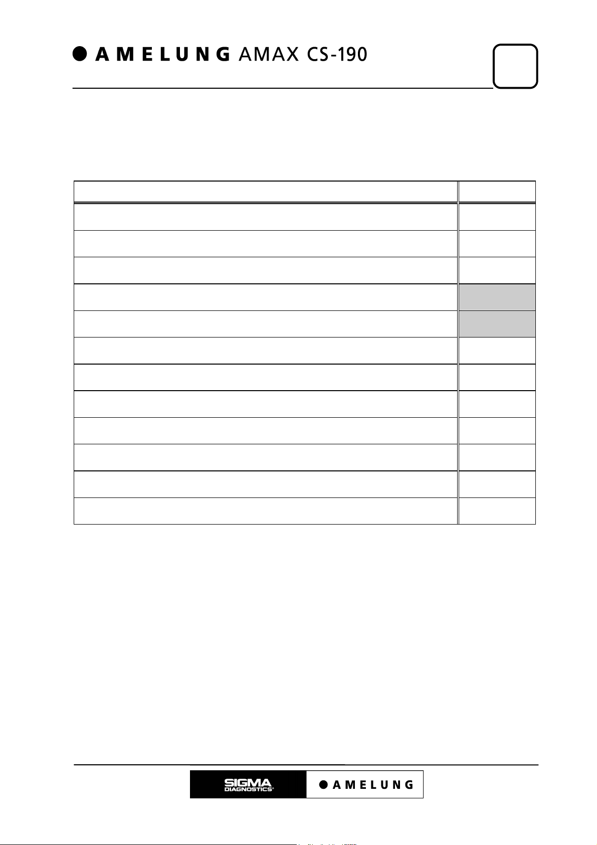
2.2 Traffic Lights
The traffic lights are positioned in the upper, right corner of the AMAX CS-190 next to
the dilutor unit (user position in front of the instrument). The light signals have the
following meanings:
Tab. 2.2.1
Light signal Meaning
no light
green light
yellow light WARNING: missing cuvettes, waste water reservoir full, fresh
red light ERROR: temperature outside operating range, photometer lamp
green + red light ERROR: XYZZ - waste water well full
running light CANCEL: press any key - Instrument is aborting current process.
AMAX CS-190 software booted, no errors registered, processing
not yet started.
AMAX CS-190 software booted, no errors registered, processing
started
water reservoir empty, plasma-reagent-tray cover open,
photometer lamp switched off
not yet ready
2.3 Pictograms
This service manual describes the maintenance and repair of the automatic coagulation
instrument AMAX CS-190.
These instructions are written for qualified medical and technical personnel.
IMPORTANT!
Read these instructions carefully and work only in the prescribed
manner!
Pay attention to warnings and notices!
Only in this way can damage to man and machine be avoided!
2 – 2 June, 98
Introduction
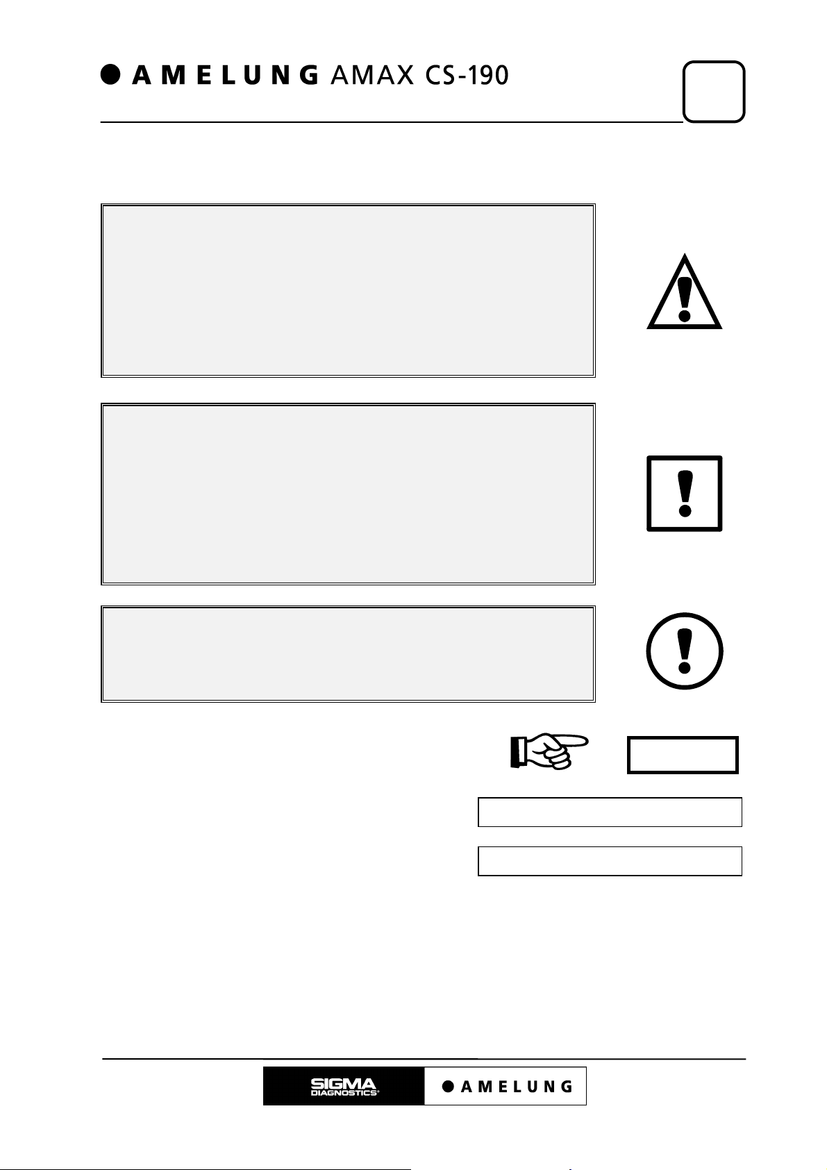
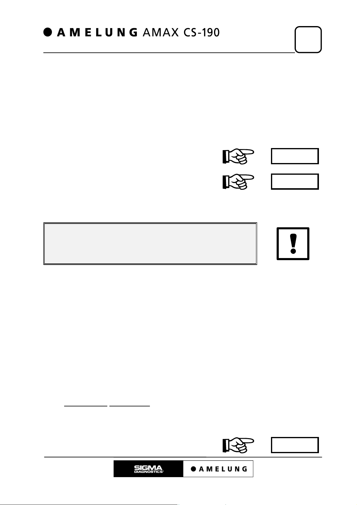
To increase the overall understanding of this manual, the following pictograms are
used:
ATTENTION!
There is DANGER TO LIFE of the user!
Read these instructions carefully and work only in the prescribed
manner!
Pay attention to warnings and notices!
Only in this way can damage to man and machine be avoided!
2
ATTENTION!
The AMAX CS-190 can be damaged!
Read these instructions carefully and work only in the prescribed
manner!
Pay attention to warnings and notices!
Only in this way can damage to man and machine be avoided!
IMPORTANT / NOTICE!
Requires additional operator action
or alteration of the adjustment parameters.
also see chapter
#
one turn to the ‘right’ (clockwise)
one turn to the ‘left’ (anti clockwise)
Amelung specific part number
1¬
1«
(Q00000)
Key on the PC-keyboard
June, 98 2 – 3
<X>

Safety Regulations
3. Safety Regulations
3
3.1 Information on How to Avoid Danger to Life and
Health
3.1.1 General Information
3.1.2 Information on the Repair of the AMAX CS-190
3 – 1
3 – 1
3 – 1
June, 98 3 – 0
Safety Regulations
3
It is guaranteed that the user is protected from danger to life and health
when using the AMAX CS-190 in compliance with the regulations (§ 3(1)
MedGV).
3.1 Information on How to Avoid Danger to Life and Health
3.1.1 General Information
• If the AMAX CS-190 shows any defects which might endanger patients or user
personnel, it must not be operated (§ 6(1) MedGV).
• Wear protective clothing, especially protective gloves. It is a possibility that infected
plasma (dangerous substances) might be touched.
• Protective clothing, especially protective gloves which were in contact with
dangerous substances (e.g. infected plasma) have to be changed and disposed
immediately (Technical rules for dangerous Substances (TRGS)).
• Plasma samples, reagents and waste water are toxic waste. The toxic waste has to
be disposed in compliance with the operative regulations (laboratory regulations).
3.1.2 Information on the Repair of the AMAX CS-190
• While under repair the instrument must not be used for testing.
• After a repair, the AMAX CS-190 has to undergo a functionality check. This involves
the carrying out of checking measurements. These actual values have to be
equivalent to the theoretical values.
ATTENTION!
Live parts (power unit and connection panel) must not be
touched!
DANGER TO LIFE!
ATTENTION!
On certain parts (photometer lamp or lamp casing) there is a
DANGER OF BURNS!
IMPORTANT!
Regular maintenance helps to avoid malfunctions and protects
the AMAX CS-190 from damage.
June, 98 3 – 1

Accessories / Equipment
4. Accessories / Equipment
4.1 Measurement and Adjustment Tools for Repairs 4 – 1
4
June, 98 4 – 0
Accessories / Equipment
4
4.1 Measurement and Adjustment Tools for Repairs
It is recommended to always carry the following tools and adjustment gauges at every
AMAX CS-190 service intervention:
Tab. 4.1.1
Measuring instruments / Tools Catalog no.
Thermometer 121563
Surface probe 121565
Immersion probe 121564
Digital multimeter
Oscilloscope incl. probes: 1:1 / 1:10
Adjustment gauge I (magazine light barriers) J01847
Adjustment gauge II (row pusher end light barrier) J01827
Adjustment gauge III (adjustment gauge lifting solenoid) J01819
Adjustment gauge (alignment pusher 1 unit) J01820
Needle ejector tool J01818
Spring balance 890300
Adjustment tool auto photometer height J01817
June, 98 4 – 1

Technical Data
5. Technical Data
5
5.1 Measurements
5.2 Weights
5.3 Electrical Connection Data
5.4 Temperatures
5.4.1 Temperatures of the Individual Modules
5.5 Intended Use
5.6 Throughput of the AMAX CS-190
5 – 1
5 – 2
5 – 2
5 – 3
5 – 3
5 – 4
5 – 5
June, 98 5 – 0

Technical Data
5.1 Measurements
5
AMAX CS-190
• Height
• Width
• Depth
Commander PC
• Height
• Width
• Depth
Monitor (14 inches)
• Height
• Width
• Depth
optional: Monitor (15 inches)
ca. 56 cm ( 22.5 inches)
ca. 82 cm (32.75 inches)
ca. 69 cm (27.75 inches)
ca. 12 cm ( 4.75 inches)
ca. 40 cm ( 16 inches)
ca. 44 cm (17.75 inches)
ca. 37 cm ( 15 inches)
ca. 35 cm ( 14 inches)
ca. 39 cm (15.75 inches)
• Height
• Width
• Depth
Keyboard
• Height
• Width
• Depth
Printer
• Height
• Width
• Depth
Base cabinet for the AMAX CS-190
• Height
• Width
• Depth
ca. 39 cm (15.75 inches)
ca. 39 cm (15.75 inches)
ca. 36 cm ( 14.5 inches)
ca. 4 cm ( 1.5 inches)
ca. 46 cm ( 18.5 inches)
ca. 17 cm ( 6.75 inches)
ca. 17 cm ( 6.75 inches)
ca. 36 cm ( 14.5 inches)
ca. 21 cm ( 8.5 inches)
ca. 71 cm (28.25 inches)
ca. 82 cm (32.75 inches)
ca. 69 cm (27.75 inches)
June, 98 5 – 1

5
5.2 Weights
Technical Data
• AMAX CS-190
• Base cabinet for AMAX CS-190
• Commander PC
• Monitor
• Printer
ca. 130 kg ( 286 pounds)
ca. 78 kg ( 172 pounds)
ca. 10 kg ( 22 pounds)
ca. 11 kg (24.2 pounds)
ca. 2,5 kg ( 5.5 pounds)
5.3 Electrical Connection Data
AMAX CS-190
• supply voltage
• supply frequency
• power consumption cold, max:
warm, min:
• heat emission
Commander PC
90-132 /
180-265
47-63 Hz
1240 kJ/h
VAC
690
230 VAVA
• supply voltage
• supply frequency
• power consumption
Monitor
• supply voltage
• supply frequency
• power consumption
Printer
• supply voltage
• supply frequency
• power consumption
90-132 /
180-264
50-60 Hz
145 VA
100-240 VAC
47-63 Hz
80 VA
230 VAC
50 Hz
30 VA
VAC
5 – 2 June, 98
Technical Data
5
5.4 Temperatures
The internal components of the Amelung Amax CS-190 are heated or cooled
automatically. In order to guarantee the perfect performance of the AMAX CS-190, the
following instructions have to be followed:
• The AMAX CS-190 must not be placed directly in front of a wall.
(minimum distance 15 cm)
• The ventilation grids must never be obstructed in any way.
(Cooling the AMAX CS-190 would be impossible)
• The system fluid supply has to be sufficient at all
times.
• To provide a sufficient air flow, the air filter has to
be clean.
• Do not expose the AMAX CS-190 to direct sunshine. The room temperature must
not exceed 32°C.
9.1
9.2
ATTENTION!
Disregard may lead to malfunction of and cause damage to the
AMAX CS-190!
5.4.1 Temperatures of the Individual Modules
• reagent plasma barcode tray ca. 16.5 ± 1.5°C
• incubation rail ca. 37.5 ± 0.3°C
• optical measuring unit ca. 37.5 ± 0.3°C
• mechanical measuring unit ca. 37.5 ± 0.3°C
• cuvette magazine ca. 37.5 ± 0.3°C
• pre-heater ca. 40.0 ± 0.5°C
• cooling water system ca. 25 - 55°C
• warm water circuit (37°C)
washing in the well ca. 38.5 ± 0.5°C
pumping in the well ca. 38.5 ± 0.5°C
The temperature in the well is measured by a liquid thermometer.
In the user software
is measured during the process “Wash” and “Fill”.
The warning limits for the temperatures can be entered in the user interface software.
(main menu), select “Maintenance”, then “Wash”. The temperature
In the case of a divergence, a message will be
displayed on the monitor and the status lights will
June, 98 5 – 3
2.2

5
show yellow.
In addition, an acoustic signal will sound and the AMAX CS-190 will not reactivate.
Technical Data
5.5 Intended Use
The AMAX CS-190 measures in-vitro coagulation times and chromogenic test
reactions. Both citrated whole blood and citrated plasma samples can be used.
You can choose between the mechanical measuring and the optical measuring mode.
Depending on the used reagents and measuring methods the following hemostasis
parameters can be determined:
• Prothrombin time (PT/Quick)
• Hepato-Quick
• Activated Partial Thromboplastin Time (APTT)
• Thrombin time (TT)
• Fibrinogen (Clauss)
• Fibrinogen (derived, optical density measurement)
• Normotest
• Thrombotest
• Factor assays: II, V, VII, VIII, IX, X, XI and XII
• AT III
• Plasminogen
• Antiplasmin
• PAI
• Heparin
• Protein S
• Protein C
• APC-Resistance
• and more
5 – 4 June, 98
Technical Data
5
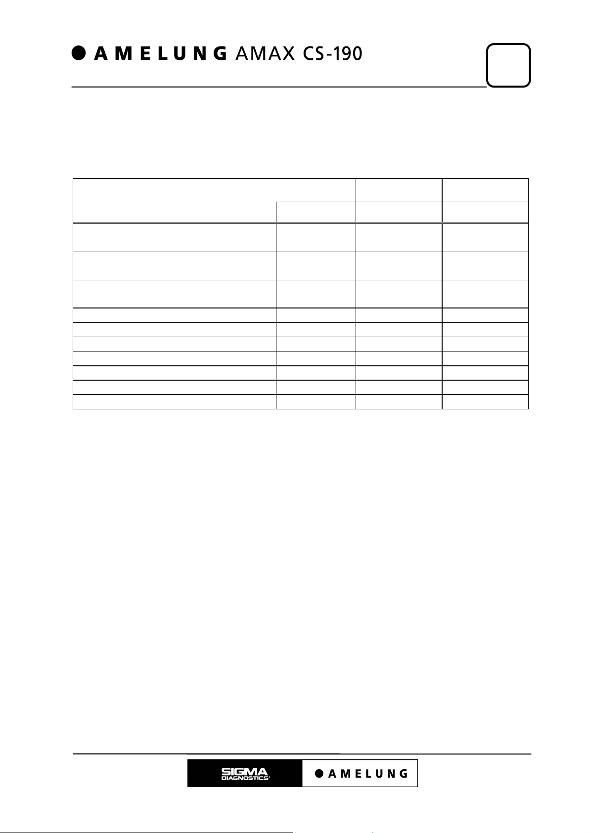
5.6 Throughput of the AMAX CS-190
The throughput of the AMAX CS-190 is influenced by the type of measuring method
used.
Tab. 5.6.1
patients/hour patients/hour
PT-mechanical
(pipetting mode 0)
PT- mechanical
(pipetting mode 2)
PT-optical
(pipetting mode 0)
PT-optical, derived fibrinogen 240 120 60
APTT-mechanical or optical 110 110 55
Fibrinogen (Clauss) 115 115 57
AT III 80 80 40
Factor assays 120 120 60
PT-mechanical/APTT 120 60 30
PT-mechanical/APTT/AT III 90 30 15
tests/hour single double
180 180 90
240 240 120
190 190 95
June, 98 5 – 5

Measuring Methods
6. Measuring Methods
6
6.1 Mechanical Measuring Mode
6.2 Optical Measuring Mode (Clotting)
6.3 Optical Measuring Mode (Chromogenic)
6 – 1
6 – 2
6 – 4
June, 98 6 – 0

Measuring Methods
The AMAX CS-190 features a mechanical and an optical measuring unit.
The mechanical measuring unit has 4 measuring cells which work with the ball method.
The optical measuring unit (photometer) has 4 measuring channels for measurement of
the optical density. The wavelength of the light is 405nm.
The necessary total volumes for the measurements are:
• Mechanical measuring mode,
• Optical measuring mode
• Maximum volume (mechanical, optical): 600µl
The individual measuring modes are described on the following pages.
minimum volume: 75µl
, minimum volume: 150µl
6
6.1 Mechanical Measuring Mode
The time between the addition of the starting reagent and the beginning of the
formation of fibrin is measured.
The sample and if necessary the reagent and/or buffer are pipetted into a measuring
cuvette. After the incubation time it is placed into one of the mechanical measuring
channels automatically.
There is a special steel ball on the bottom of the cuvette.
With the addition of the starting reagent, the cuvette starts to rotate around its
longitudinal axes while the ball is held in a certain position by a magnet.
As coagulation begins, the ball is removed from its position by the forming fibrin
threads, because the force of the magnet is overcome. A sensor detects the change of
the ball’s position and ends time measurement.
Pic. 6.1.1
schematic display of the
mechanical measuring mode
cuvette
sensor
magnet
June, 98 6 – 1
6
A
Measuring Methods
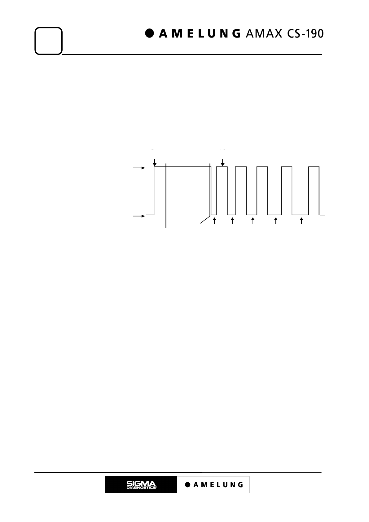
Impulse measurement
In order to detect very unstable clots with the mechanical method, the continuous
rotation of the cuvette can be changed to a rotation with intervals after a predefined
time.
In the example on Pic 6.1.2, the continuous movement is switched to interval
movement after 25.6s. During the intervals, which prolong automatically, a clot cannot
be detected, but it has time to stabilise itself. The CV rises in dependence with the
length of the interval.
Pic. 6.1.2
Impulse measurement
Cuvette
rotates
Cuvette
stops
dd ition s tarting
reagent
activation
4s
Begin of
impulsemovement
25 .6 s
Movement:
½ rotation
pause
0.2s
pause
+0.1s
pause
+0.2s
pause
+0.3s
pause
+0.4s
6 – 2 June, 98
[s]
t
Measuring Methods
6
6.2 Optical Measuring Mode (Clotting)
The time between the addition of the starting reagent and the beginning of the
formation of fibrin is measured.
The sample and if necessary the reagent and/or buffer are pipetted into a measuring
cuvette. After the incubation time it is placed into one of the optical measuring channels
automatically.
The timing begins with the addition of the starting reagent. The intensity of the light
beam that passes through the cuvette is monitored by a sensor. When clots are
forming, the sample/reagent mixture becomes cloudy and the intensity of the light
reaching the sensor decreases (turbidimetrical measurement).
As soon as the change in the optical density reaches a pre-set threshold, the time
measurement stops.
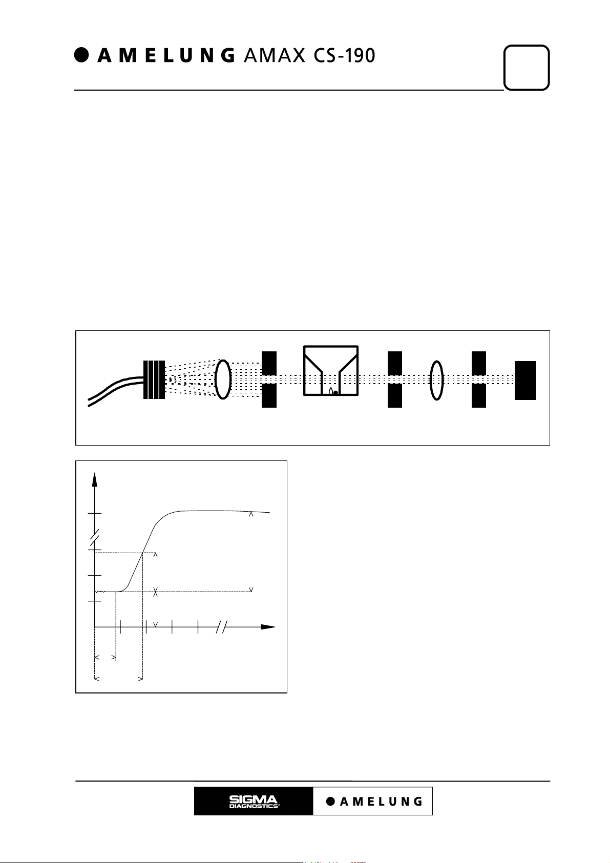
Pic. 6.2.1 schematic display of the optical measurement (clotting)
Optical wave guide filter lens aperture cuvette aperture lens aperture sensor
Pic. 6.2.2
Analysis of the optical measurement (clotting)
mE
The coagulation time t2 is the time taken
from addition of the starting reagent to the
point when the absorbance change has
30
15mE
20
0
E
1-E
achieved the predefined threshold value.
The absorbance change is measured from
the stable baseline value at E
0.
Example: 15mE (threshold value).
10
0
E
The derived fibrinogen is calculated from
10 20 30
lag-
1
phase
Coag. time
t
t
2
the difference between the maximum
absorbance E
1 and the baseline value E0.
June, 98 6 – 3
6
Measuring Methods
6.3 Optical Measuring Mode (Chromogenic)
The rate of absorbance change is measured at predetermined intervals.
Sample and reagent are pipetted into a measuring cuvette and placed into one of the
optical measuring channels. After the addition of the starting reagent, measurements
are taken in defined intervals.
A monochrome light beam (405nm) passes through the cuvette. The change in optical
density is measured by a sensor behind the cuvette at pre-defined intervals (kinetic
measurement).
The values of change in mE/t are further mathematically processed.
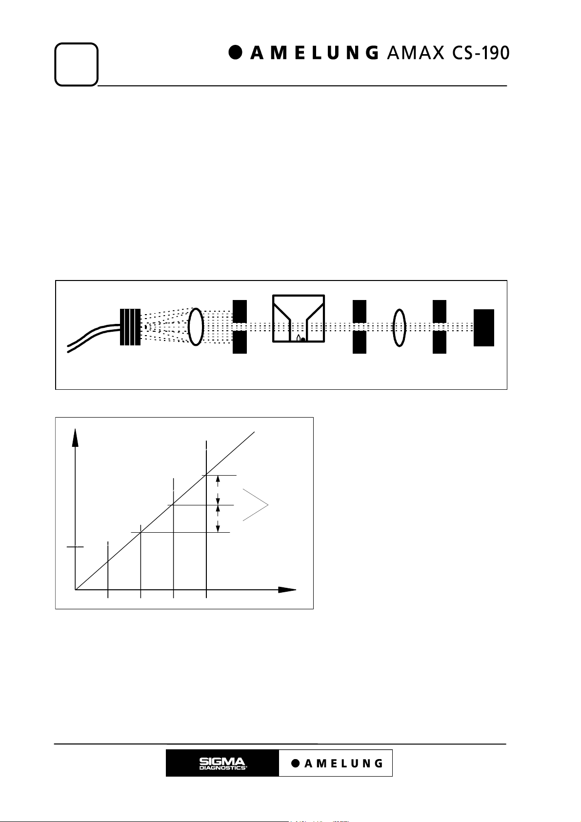
Pic. 6.3.1 schematic display of the optical measurement (chromogenic)
Light source filter lens aperture cuvette aperture lens aperture sensor
Pic. 6.3.2
Analysis of the optical measurement
(chromogenic)
E
The absorbance increase within a
25mE
50mE/min
25mE
defined interval (30/60/90) is
measured and converted into
E/min.
The rate of absorbance change
must be constant (linear).
60
90
t[s]
6 – 4 June, 98

Instrument Installation
7. Instrument Installation
7
7.1 Instrument Overview
7.2 Installation of the AMAX CS-190
7.3 PC & Accessories
7.3.1 Jumper Settings of the AML-BUS-PC-Board
7.3.2 Jumper Settings of the Modem Boards
7.4 Printer Installation
7.5 Connections
7.5.1 Fresh Water / Waste Water System
7.5.2 Electrical Connections
7.6 Turning on the Instrument
7 – 1
7 – 2
7 – 3
7 – 4
7 – 4
7 – 5
7 – 7
7 – 7
7 – 8
7 – 9
June, 98 7 – 0
Instrument Installation
5
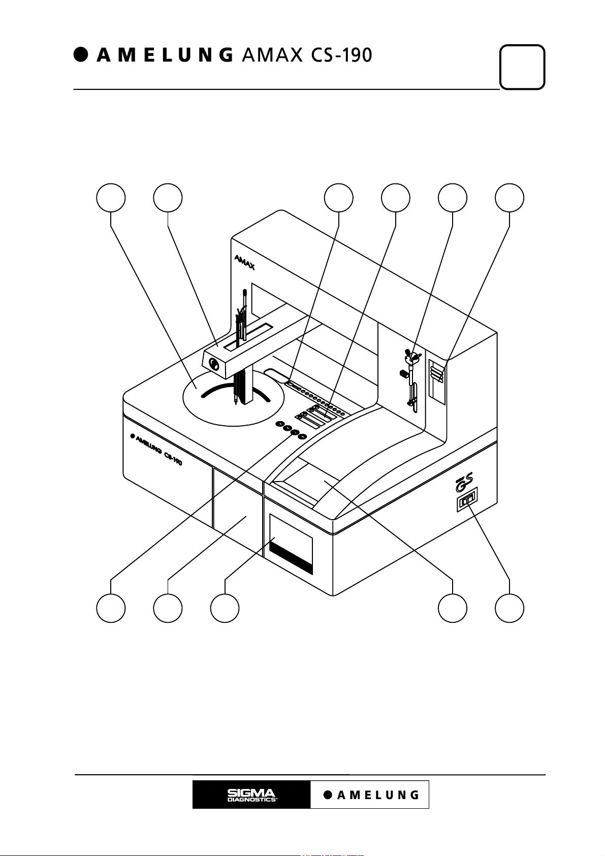
7.1 Instrument Overview
Pic. 7.1.1
6 7 8 9 10 11
7
1234
June, 98 7 – 1
7
Tab. 7.1.1
Instrument Installation
Overview
1. Mains switch 7.5
2. Cuvette magazine (front feed chute) 8.3 / 11.3
3. Cuvette magazine (front disposal chute) 8.3 / 11.3
4. Drawer (Disposal) 9.8
5. Mechanical measuring unit 8.2 / 11.2
6. Reagent-plasma-barcode 8.4 / 11.4
7. Robot (XYZZ) 8.6 / 11.6
8. Incubation rail 8.3 / 11.3
9. Photometer 8.5 / 11.5
10. Dilutor 8.1 / 11.1
11. Traffic lights 2.2
[Chapter]
7.2 Installation of the AMAX CS-190
1. Remove the packaging material of the AMAX CS-190 and level the instrument on
the base cabinet.
Fasten the connecting bolts which connect the base cabinet and the instrument.
2. Do not turn on the instrument yet!
All movable parts were secured for transport.
(XYZZ-robot: all axes were secured)
Remove all shipping clamps.
(check driving belt XY-axes, tapes, paper boards, etc.)
Check all movable parts for free movement.
3. Check the system coolant level,
if necessary fill up with original system liquid.
(830040 (500ml bottle)).
4. Configure PC & Accessories.
5. Connect the fresh/waste water reservoir and the
liquid level sensors.
6. Establish all electrical connections between the
PC and the AMAX CS-190.
7. Now the AMAX CS-190 can be turned on.
7 – 2 June, 98
9.1
7.3
7.5
7.6
Instrument Installation
ATTENTION!
Remove all shipping clamps and securing devices before turning
on the instrument.
Disregard may lead to malfunction of and cause damage to the
AMAX CS-190!
Packaging material is recycable!
7.3 PC & Accessories
7
1. Remove all packaging material of the PC, monitor, printer, etc.
In case the AML-Bus-Board (Board PH-PC (D02801)) or the modem board (Z04005)
have not yet been installed, the PC has to be opened and the boards have to be
placed into free slots.
Check and correct the jumper settings (see below) before the installation. Disregard
may lead to malfunction or conflicts with other components.
2. Connect all components (except for the PC and the AMAX CS-190!) and establish
all electrical connections.
3. Install the software:
First, switch on the PC, screen and printer. The PC installs its operating system
automatically (selection: WINDOWS 3.1) After approx. 30 min. the installation is
complete and you can continue by yourself. Deinstall WINDOWS with only the DOS
prompt remaining on the hard drive.
Now the main software can be installed.
It consists of three or five 3,5” disks:
a. Disk with main menu AMAX CS-190
b. Disk for service software
c. Disk for AMAX CS-190 (instrument specific data)
d. Disk for modem software (option)
e. Disk for printer driver
(printer specific)
7.4
June, 98 7 – 3
7
7.3.1 Jumper Settings on the AML-BUS-PC-Board
There are two dip-switches on the Board PH-PC for adjusting the address.
The following switch adjustments have to be made so that the board can be identified:
Tab. 7.3.1
Dip-switch S1 Position Dip-switch S2 Position
Switch 1 on Switch 1 on
Switch 2 on Switch 2 off
Switch 3 on Switch 3 off
Switch 4 off Switch 4 off
ATTENTION!
Disregard may lead to malfunction of the AMAX CS-190!
Instrument Installation
7.3.2 Jumper Settings of the Modem Boards
The different modems are not distinguishable by their names. For their differentiation,
the BZT-No. is used here. This BZT-No. is printed on the packaging and on a label on
the modem itself.
Tab. 7.3.2
Designation Switch position for Com 3 IRQ 5
Internal fax-modem BZT-No.
(Company)
BZT - No. A109 822D
BZT - No. A107 434D
(YAKUMO)
BZT - No . A121 250F
(CREATIX)
BZT - No. A106 901D
The initialisation string for these modems is:
ATE0Q0V0L1X3%C1\N3\V1S0=2S7=100^M
2 and 7 (7 is a soldering bridge)
switch 1 and 6 to ON
all others to Off
switch 1 and 6 to ON
all others to Off
2,3,8
ATTENTION!
Disregard may lead to malfunction of the AMAX CS-190!
7 – 4 June, 98

Instrument Installation
7
7.4 Printer Installation
There are different types of printer which can be used in combination with the AMAX
CS-190.
Examples for installation:
1. Printer type Canon BJC-240
An installation disk (BJ-setup program) for DOS
Installation is carried out according to the disk label or the printer’s user manual
(directory: C:\bjprn). The printer has to be turned on and connected to the PC.
After the initiation of the printer software the settings of the printer control mode can
be checked. The mode must be set to LQ-Mode
adjusted data has to be transferred to the printer with the function key <F10>.
ATTENTION!
Disregard may lead to malfunction of the AMAX CS-190!
is delivered along with the printer.
. To complete the installation, the
2. Printer type Canon BJ-200
There is no installation disk for this printer. This printer is adjusted manually by
using the dip switches:
Tab. 7.4.1
Dip-switch Position
Switch no. 01 on
Switch no. 02 on
Switch no. 03 off
Switch no. 04 on
Switch no. 05 on
Switch no. 06 off
Switch no. 07 on
Switch no. 08 off
Switch no. 09 off
Switch no. 10 on
Switch no. 11 off
Switch no. 12 off
ATTENTION!
Disregard may lead to malfunction of the AMAX CS-190!
June, 98 7 – 5

7
3. Printer type Canon BJ-200 ex
There is no installation disk for this printer. This printer is adjusted manually by
using the dip switches:
Tab. 7.4.2
Dip-switch Position
Switch no. 01 on
Switch no. 02 on
Switch no. 03 off
Switch no. 04 on
Switch no. 05 off
Switch no. 06 off
Switch no. 07 off
Switch no. 08 off
Switch no. 09 off
Switch no. 10 off
Switch no. 11 on
Switch no. 12 off
Instrument Installation
ATTENTION!
Disregard may lead to malfunction of the AMAX CS-190!
7 – 6 June, 98

Instrument Installation
7
7.5 Connections
7.5.1 Fresh Water / Waste Water System
There is a connection panel for the fresh water / waste water system. Pic. 7.5.1.1
shows the connection panel.
Connect the tubing (Q90006 / Q90007) with the panel and each fresh water / waste
water reservoir (Q90004 / Q90005). In order to ensure perfect functioning, the tubing
connectors have to lock into place precisely (audible). The tubing sets each have a
cable with a BNC connector, which also have to be connected. The cables must not be
interchanged because they are the control cables for the liquid level sensors in the
reservoirs. Pic. 7.5.1.2 shows the position of the reservoirs. Pic. 7.5.1.3 shows the
connections of a reservoir.
ATTENTION!
Disregard may lead to malfunction of the AMAX CS-190!
Pic. 7.5.1.1
Connection panel with level
sensor connections
1
34
Pic. 7.5.1.2
Position of the reservoirs in the base cabinet
3
2
1
1. Base cabinet (left door)
2. Waste water reservoir
3. Fresh water reservoir
1. Plug contact - Fresh water level
sensing
2
2. Fresh water connection
3. Plug contact - Waste water level
sensing
4. Waste water connection
Pic. 7.5.1.3
Reservoir screw-lid with connections
12
3
4
1. Tubing
2. Connection socket for the tubing
3. Cable - Level sensor
4. Connection socket for the cable
June, 98 7 – 7

7
7.5.2 Electrical Connections
67 891011
Pic. 7.5.2.1
Before working on the electrical connections:
Instrument Installation
12345
IMPORTANT!
AMAX CS-190, PC, monitor and printer have to be turned off
(switch position 0/AUS or OFF).
Pic 7.5.2.1 No. 1 shows the instrument main switch.
Technical data:
Switch:
Version (230V / 3.5A) (244210)
Version (110V / 6A) (244216)
The instrument fuse (reversible fuse) is positioned inside the
mains switch. Replacing it after an activation is not necessary!
Disregard may lead to malfunction of the AMAX CS-190!
ATTENTION!
ATTENTION!
7 – 8 June, 98

Instrument Installation
7
On the rear side of the AMAX CS-190 is a
connection panel for the electrical connections
(user position in front of the instrument).
Connect the 15-pin AML-Bus-cable (X10183)
between the AMAX CS-190 and the PC.
The cable has to be screwed into the panel and the
PC correctly in order to function normally.
Now connect the power cable to the AMAX CS-190
and a suitable power supply. (Fuse protection: 16A
(safety cut-out: slow)).
In addition, PC, monitor and printer have to be
connected to the power supply.
Pic. 7.5.2.2
Connection panel
1
2
1. AML-Bus connection
2. Power connection
5.3
ATTENTION!
Disregard may lead to malfunction of the AMAX CS-190!
7.6 Turning on the Instrument
If you have completed all steps successfully, you now may switch on all devices:
First turn on the AMAX CS-190, then all other components!
The AMAX CS-190 moves to its home position (all modules are initialised).
The instrument is ready when the traffic light shows
no light and the screen shows the main menu.
ATTENTION!
The instrument must not be turned on and off in short intervals
(wait at least 10-15 seconds).
Disregard may lead to malfunction of the AMAX CS-190!
2.2
June, 98 7 – 9

Subassemblies
8. Subassemblies
8
8.1 Dilutor
8.1.1 Adjusting the Temperature of the Pre-heater
8.2 Mechanical Measuring Unit
8.2.1 Removing the Measuring Unit
8.2.2 Adjusting the Measuring Block Temperature
8.2.3 Adjusting the PC Temperature Display
8.2.4 Adjusting the Inductive Ball Sensors
8.2.5 Adjusting the Hinge Mechanism Voltage (knee joint)
8.2.6 Adjusting the Rotational Speed
8.2.7 Adjusting the Motor Torque Voltage of the
Measuring Units
8.2.8 Adjusting the Dip-switches on the PH-M-MB
(D05601) Board
8.3 Cuvette Magazine
8.3.1 Removing the Cuvette Magazine or the Incubation
Rail
8.3.2 Adjusting the Mixer in the Incubation Rail (Q10005)
8.3.3 Adjusting the Ejector (Q10030)
8.3.4 Checking the Lifting Solenoid of the Incubation Rail
8.3.5 Adjusting the Temperature of the Incubation Rail
8.3.6 Adjusting the PC Temperature Display
8.3.7 Checking the Lifting Solenoids
8.3.8 Alignment Tools Magazine
8.3.9 Adjusting the Pusher 1 Unit
8.3.10 Alignment of the Cuvette Magazine in the
AMAX CS-190
8.3.11 Adjusting the Light Barriers and the Cuvette Comb
8.3.12 Adjusting the Cuvette Comb
8.3.13 Checking the Reflex Light Barriers
8.3.14 Checking the Conveyors
8.4 Reagent-Plasma-Barcode
8.4.1 Adjusting the Cooling Circuits
8.4.2 Adjusting the PC Temperature Display
8.4.3 Adjusting the Cutoff Voltage of the Servo Power
Amplifier
8.4.4 Adjusting the Mixer Voltage
8.4.5 Mechanical Reset Adjustments at the RPB
8.4.6 Adjusting the Barcode Scanner Position
8.5 Photometer
8.5.1 Removing the Measuring Unit
8.5.2 Adjusting the Temperature of each Measuring
Channel
8.5.3 Adjusting the Photometer Lamp Voltage
8.5.4 Adjusting the Photometer Measuring Amplifier
8.6 XYZZ-Robot (gantry)
8.6.1 Adjusting the Safety Systems of the Control Unit
8 – 1
8 – 2
8 – 3
8 – 4
8 – 4
8 – 5
8 – 5
8 – 6
8 – 7
8 – 7
8 – 8
8 – 9
8 – 11
8 – 11
8 – 12
8 – 12
8 – 13
8 – 13
8 – 14
8 – 15
8 – 16
8 – 16
8 – 18
8 – 20
8 – 22
8 – 23
8 – 24
8 – 25
8 – 25
8 – 26
8 – 26
8 – 27
8 – 27
8 – 29
8 – 30
8 – 30
8 – 31
8 – 31
8 – 34
8 – 35
June, 98 8 – 0

8
Subassemblies
8.6.2 Voltage Cutoff of the X-Motor Amplifier
8.6.3 Voltage Cutoff of the Y-Amplifier
8.6.4 Speed Cutoff of the X-Motor Amplifier
8.6.5 Mechanical Reset Adjustment of the XYZZ-Robot
8.6.6 Adjusting the XY-Motors
8.6.7 Adjusting the Level Sensors (liquid level sensors
and height sensors)
8.7 Water Temperatures
8.7.1 Adjusting the Water Reservoir II Temperature
(D10068)
8.7.2 Adjusting the PC Temperature Display
8 – 35
8 – 36
8 – 37
8 – 38
8 – 39
8 – 40
8 – 42
8 – 43
8 – 43
8 – 0 June, 98

Subassemblies
8.1 Dilutor
8
Pic. 8.1.1
Dilutor unit (10)
Tab. 8.1.1 Structure dilutor unit (Q10007)
mechanical subassemblies electronic subassemblies
Dilutor component XL 3000W (246005)
Pre-heater (Q10020)
There is a dip-switch on the PH-MCK II board for adjusting the module address. It also
contains the program-IC (integrated chip) IC1, which can be replaced to update to a
new program version.
67 891011
12345
AM-DIL board (D05701)
PH-MCK II board (D03601)
The following switch adjustments have to be carried out so that the module can be
identified.
Tab. 8.1.2
Dip-switch S1 position
Switch no. 1 on
Switch no. 2 off
Switch no. 3 off
Switch no. 4 off
Module address: 1
ATTENTION!
Disregard can lead to malfunction of the AMAX CS-190!
June, 98 8 – 1

8
8.1.1 Adjusting the Temperature of the Pre-heater
In order to carry out the adjustments, the following instrument casings have to be
removed:
Rear casing (123268)
The pre-heater is positioned in the top left corner (dilutor unit) of the instrument (user
position behind the instrument).
Pre-heater (Q10020) (1)
Heating:
PH-I-HZ II board (D01101) (2)
Subassemblies
Pic. 8.1.1.1
1
2
The theoretical value of the heating is adjusted on the PH-I-HZ II (D01101) board (on
which the pre-heater is mounted) by using the potentiometer R16.
1¬ = approx. - 1.0°C / 1« = approx. + 1.0°C
As long as the LED V1 is lit, the heating is active and the temperature rises. The
temperature of the reservoir should be 40°C ± 0.5°C .
The temperature is measured using a contact thermometer directly at the brass
container through a hole in the pre-heater insolation.
8 – 2 June, 98

Subassemblies
8.2 Mechanical Measuring Unit
8
Pic. 8.2.1
Mechanical measuring unit (5)
Tab. 8.2.1 Structure mechanical measuring unit (Q10011)
mechanical subassemblies electronic subassemblies
knee joint (D10074) AM-M-SH board (D06901)
67 891011
AM-M-HT board (D06301)
PH-TF board (D06801)
AM-S-HY board (D06201)
PH-HALL board (D05201)
12345
The PH-MCK (D00801) board is not in the module. It is integrated in the subassembly
reagent/measuring unit drive (Q10080).
There is a dip-switch for adjusting the module address on the PH-MCK board. It also
contains the program-IC (integrated chip) IC1, which can be replaced to update to a
new program version.
The following dip switch adjustments have to be carried out so that the module can be
identified.
Tab. 8.2.2
Dip-switch S1 position
switch no. 1 off
switch no. 2 off
switch no. 3 on
switch no. 4 off
Module address: 2
ATTENTION!
Disregard can lead to malfunction of the AMAX CS-190!
June, 98 8 – 3

8
8.2.1 Removing the Measuring Unit
In order to remove the measuring unit, the following instrument casings should be
removed:
Upper structure (123290)
Side casing left (123289)
Working area (123292)
Front plate left (123293)
Side casing right (123291)
Front plate right (123294)
Magazine cover (122432)
8.2.2 Adjusting the Measuring Block Temperature
The adjustments have to be carried out on the AM-M-SH (D06901) board. Place
cuvettes, filled with approx. 200 µl water in the measuring channels.
In order to adjust the temperature of the measuring unit, the following instrument
casings should beremoved:
Subassemblies
Upper structure (123290)
Side casing left (123289)
Working area (123292)
The supply voltage should be turned on. The theoretical value of the heating is adjusted
with potentiometer R27.
1¬ = approx. + 1.0°C / 1« = approx. - 1.0°C
As long as the light-emitting diode LED V4 is lit, the heating is active and the
temperature rises. The current temperature can be measured in the cuvettes using the
liquid thermometer.
The temperature should be at 37.5°C ± 0.3°C when
LED V4 goes out (after approx. 15 minutes).
The adjustment process is complete when the temperature of each cuvette is constant.
After successful adjustment, the measuring block has a temperature of approx. 38.5°C.
The temperature if measured on the sides of the aluminium block.
The adjustment can be carried out outside the instrument as well. The ambient air
around the instrument should not be too cold (avoid draughts).
The adjustment should be checked again after the measuring unit has been reinstalled.
5.4
ATTENTION!
Disregard can lead to malfunction of the AMAX CS-190!
8 – 4 June, 98

Subassemblies
8.2.3 Adjusting the PC Temperature Display
This adjustment is carried out on the PH-TF (D06801) board.
The current temperature of the measuring block can
be queried using the service program.
The displayed value can be altered (adjusted) with
potentiometer R7.
1¬ = approx. - 0.5°C / 1« = approx. + 0.5°C
The temperature should be measured on the sides of the aluminium-block using the
contact thermometer. This value should then be adjusted to approx. 38.5 °C.
IMPORTANT!
The temperature displayed by the PC in the service program
should always be equivalent to the current temperature.
11.2
8
ATTENTION!
Disregard can lead to malfunction of the AMAX CS-190!
8.2.4 Adjusting the Inductive Ball Sensors
The adjustment is carried out at the ball sensors (D10079).
The mechanical measuring unit should be operational before the adjustment. The
supply voltage should be turned on and the temperature should be adjusted correctly.
Otherwise, the temperature adjustment has to be repeated (see: Adjusting the
measuring block temperature).
An empty cuvette with a ball should be placed into every measuring channel. It is
important that all measuring channels are closed.
The voltage to be adjusted can be measured on the AM-S-HY board (D06201) at MP2
using a multimeter. First, a voltage of approx. 2.9-3.1 Volt is adjusted. The adjustment
is altered using the potentiometer in the ball sensor.
¬ = - / « = +
After an operation time of about 10 minutes, a voltage of 3.8 volts should be adjusted.
Now, in order to check its functionality, the
measuring unit can be started in the service
program.
After the measuring channels have been started, they are stopped by blocking the ball
using a non-metallic object. The LED V4 flashes once. It signals the stop-impulse.
When the measuring unit stops, the sensor system is ready for operation. The electrical
11.2
June, 98 8 – 5

8
adjustment and functionality check should be rechecked after another 15 minutes. If
necessary, 3.8 volts should be readjusted.
Finally, the ball is glued solid in the cuvette and the measuring channel is started. An
oscilloscope is now connected to MP2. The X18 plug has to be disconnected from the
AM-M-SH board or the X1 plug from the PH-M-MB board in order to interrupt the
monitoring of the AM-S-HY board. Otherwise, the measuring channels would stop
again.
An amplitude of at least 1.5 volts should be visible.
After the measurement, the X18 or X1 plugs have to be plugged back into the AM-MSH board or the AM-M-MB board.
ATTENTION!
Disregard can lead to malfunction of the AMAX CS-190!
Subassemblies
8.2.5 Adjusting the Hinge Mechanism Voltage (knee joint)
The supply voltage for the hinge mechanism stepper motors is adjusted using the
potentiometer on the AM-M-SH (D06901) board.
1¬ = approx. + 1.0 V / 1« = approx. - 1.0 V
For that purpose, a digital voltmeter is connected to the LED V2 anode. The voltage
should be 15 Volt ± 0.5 to guarantee a safe opening and closing of the hinge.
ATTENTION!
Disregard can lead to malfunction of the AMAX CS-190!
8 – 6 June, 98

Subassemblies
8.2.6 Adjusting the Rotational Speed
In order to carry out the adjustment, the following instrument casings should
beremoved:
Side casing left (123289)
Front plate left (123293)
The measuring unit should be operational.
One oscilloscope probe is connected to PIN 1 of
plug X1 on the PH-M-MB (D05601) board.
The measuring unit channel no. 4 is started with the
service program.
Using the potentiometer R21, the speed is adjusted so that the interval length of the
signal is 375ms.
1¬ = approx. - 30ms / 1« = approx. + 30ms
This equals to 80 rpm (2 impulses per rotation of the measuring unit).
11.2
8
ATTENTION!
Disregard can lead to malfunction of the AMAX CS-190!
8.2.7 Adjusting the Motor Torque Voltage of the Measuring Units
The stepper motor supply voltage used for turning the measuring units is adjusted
using the potentiometer R22 on the PH-M-MB (D05601) board.
1¬ = approx. + 300mV / 1« = approx. - 300mV
For this purpose, a digital multimeter is connected to the coil L1. The voltage must be
approx. 6 volts ± 0.3 so that the measuring units can start smoothly and safely.
ATTENTION!
Disregard can lead to malfunction of the AMAX CS-190!
June, 98 8 – 7

8
8.2.8 Adjusting the Dip-switches on the PH-M-MB (D05601) Board
In order to carry out this adjustment, the following instrument casings should be
removed:
Side casing left (123289)
Front plate left (123293)
There are two dip-switches on the PH-M-MB board: dip-switch S1 affects the stepper
motors (complete- or half-step, direction of rotation); dip switch S2 affects the number
of measuring units.
The following dip switch adjustments have to be carried out so that the mechanical
measuring unit can function correctly.
Tab. 8.2.8.1
Dip-switch S1 position Dip-switch S2 position
switch no. 1 on switch no. 1 off
switch no. 2 on switch no. 2 on
switch no. 3 on switch no. 3 on
switch no. 4 off switch no. 4 off
Subassemblies
ATTENTION!
Disregard can lead to malfunction of the AMAX CS-190!
8 – 8 June, 98

Subassemblies
8.3 Cuvette Magazine
8
Pic. 8.3.1
Cuvette magazine (2 & 3)
Tab. 8.3.1 Structure cuvette magazine (D10007)
mechanical subassemblies electronic subassemblies
Pusher I (D10032)
Pusher II (D10033)
Side part I (D10060)
Side part II (D10061)
Conveyor I (D10062)
Conveyor II (D10063)
Lifting solenoid stops (D10038)
Incubation rail (Q10005)
67 891011
12345
PH-K5 board (D03401)
PH-MCK board (D08001)
There is a dip-switch for adjusting the module address on the PH-MCK board. It also
contains the program-IC (integrated chip) IC1, which can be replaced to update to a
new program version.
The following dip switch adjustments have to be carried out so that the module can be
identified.
Tab. 8.3.2
Dip-switch S1 position
switch no. 1 off
switch no. 2 off
switch no. 3 on
switch no. 4 on
Module address: 3
ATTENTION!
Disregard can lead to malfunction of the AMAX CS-190!
June, 98 8 – 9

8
Subassemblies
Cuvette magazine cover (1)
Cuvette box loading area (2)
Cuvette box disposal chute (3)
Cuvette box (4)
Pic. 8.3.2
123 4
Cuvette box loading area (1)
Cuvette box (2)
Cuvette comb (3)
Feed conveyor (4)
Disposal conveyor (5)
Row pusher (6)
Incubation rail (7)
Pic. 8.3.3
7
6
5
4
3
2
1
8 – 10 June, 98

Subassemblies
8.3.1 Removing the Cuvette Magazine or the Incubation Rail
In order to remove the cuvette magazine or the incubation rail, the following instrument
claddings should be removed:
Upper structure (123290)
Side cladding left (123289)
Work area (123292)
Front plate left (123293)
Side cladding right (123291)
Front plate right (123294)
Magazine cover (122432)
After that each module can be removed. The corresponding cable connections have to
be detached: supply voltage, module connections, light barrier cable, BUS-connections.
8.3.2 Adjusting the Mixer in the Incubation Rail (Q10005)
In order to carry out the adjustment, the following instrument claddings should be
removed:
8
Upper structure (123290)
Side cladding left (123289)
Work area (123292)
The incubation rail (2) with the integrated mixer
unit (D10071) is positioned under the incubation
rail cover. The mixer-position (4) is in front of the
ejector-position (3) and the lifting solenoidposition (4). (Blocking position1).
The mixer can be started with the service
program.
The ball turns when a cuvette is positioned on
the mixer position.
A stroboscopic effect can be observed when a line-powered (electric discharge lamp/
fluorescent lamp) lamp is held above the cuvette (assuming the rotational speed has
been adjusted correctly). When the rotational speed is correct, “3-4 stationary balls”
can be observed.
Pic. 8.3.2.1
1
23
45
The rotational speed is adjusted with the potentiometer R43 on the PH-K1 (D03001)
board.
¬ = - / « = +
June, 98 8 – 11

8
8.3.3 Adjusting the Ejector (Q10030)
Subassemblies
The cuvette ejector (6) plunger (1) is adjusted with the
alignment gauge (J0XXX). The ejector unit (6) has to
be connected to the incubation rail (5). The plunger is
brought into the lower position. The alignment tool (3)
is then held into the incubation rail. The short spike
(4.5mm) has to be placed into the plunger exit position.
The flat surface of the alignment gauge should now lie
on the base of the incubation rail (4). Otherwise the
two set-screws in the fish-plate (7) have to be loosened
which allows the plunger to be pushed downwards until
the flat surface of the alignment gauge comes to rest
on the incubation rail base. The upper flat surface (2)
of the plunger has to be 4.5mm deeper than the base
of the incubation rail (4).
It must not be possible to move the plunger upwards
against the alignment gauge. In this case, the ejectorplunger-position would be too deep.
After completing the alignment, the set-screws have to
be tightened again.
Pic. 8.3.3.1
5
6
1
2
3
4
Nach Einstellung
wieder festziehen!
7
4.5 mm
ATTENTION!
Disregard can lead to malfunction of the AMAX CS-190!
8.3.4 Checking the Lifting Solenoid of the Incubation Rail
In the incubation rail is a lifting solenoid (see Pic. 8.3.2.1 no.4) which blocks the
position 1(ejector position).
The function of the lifting solenoid can be checked
with a continuous test program in the service
11.3
program.
The lifting solenoid is activated and then powered
off, it should spring out without any delay.
8 – 12 June, 98

Subassemblies
8.3.5 Adjusting the Temperature of the Incubation Rail
8
The supply voltage has to be turned on. The
adjustment is carried out on the AM-I-HZ
(D07401) board. Two cuvettes (2), which are filled
with approx. 200 µl water, are placed into the
incubation channel (1) (see Pic. 8.3.5.1).
The theoretical value of the heating is adjusted with
the potentiometer R22. As long as the LED V1 is lit,
the heating is active and the temperature increases.
The temperature in the cuvettes should be at 37.5°C
± 0.3°C.
The actual temperature in the cuvettes can be measured with the liquid thermometer.
1¬ = approx. - 1°C / 1« = approx. + 1°C
ATTENTION!
Disregard can lead to malfunction of the AMAX CS-190!
Pic. 8.3.5.1
1
2
5.4
8.3.6 Adjusting the PC Temperature Display
The current temperature of the measuring unit can
be queried with the service program.
The displayed value is matched to the adjusted value (value displayed on the
thermometers) using the potentiometer R23.
1¬ = approx. + 0.5°C / 1« = approx. - 0.5°C
IMPORTANT!
The temperature displayed on the PC in the service program
should always be equal to the true temperature!
11.3
June, 98 8 – 13

8
8.3.7 Checking the Lifting Solenoids
Before aligning the cuvette magazine the function of the lifting solenoids should be
checked (stop pins for the 1st cuvette box).
The lifting solenoids (stop pins for the positioning of
the 1st cuvette box) can be “extended” or “retracted”
with the service program.
In the retracted position, the pins have to be sunk completely so that the cuvette boxes
can be transported over them without hitting them.
”Extension“ of both pins should happen at the same time if possible so that accurate
positioning of the cuvette box can be guaranteed. In addition, the lifting solenoids pins
should be positioned in the center of the “conveyor 1” plate borings. Should one of the
steps not be carried out correctly, the lifting solenoids have to be checked and
realigned if necessary.
IMPORTANT!
The lifting solenoids should not be turned on for longer
than 30 sec!
Subassemblies
11.3
ATTENTION!
Disregard can lead to malfunction of and cause damage to the
AMAX CS-190!
8 – 14 June, 98

Subassemblies
8.3.8 Alignment Tools Magazine
8
Pic. 8.3.8.1
Highest point for
cuvette comb
(1)
Alignment gauge I (J01847)
Step
(magazine light barriers)
Check position
(2)
Alignment gauge (J01820)
(Alignment Pusher Unit 1)
(3)
Alignment gauge III (J01819)
(gauge lifting solenoid)
(4)
Alignment gauge II (J01827)
(light barrier for row pusher end position)
2
1
Base surface
3
Cuvette comb
driven back
IMPORTANT!
All alignment gauges have to be removed after the alignment!
4
June, 98 8 – 15

8
8.3.9 Adjusting the Pusher 1 Unit
Subassemblies
The alignment of the Pusher Unit 1 can
be checked after inserting the
alignment gauge (6) (J01820) and
attaching it with the centering pins (4)
and the fastening screw (5). The base
plate of Pusher Unit 1(1) should lie on
the alignment gauge support points
and the whole unit should fit closely to
the alignment gauge impeders (2)
In order to carry out the alignment, the
four M4 nuts have to be unscrewed so
that moving the unit is possible.
After completing the alignment, tighten
the nuts and remove the alignment
gauge.
Pic. 8.3.9.1
1
2
3
4
5
6
ATTENTION!
Disregard can lead to malfunction of and cause damage to the
AMAX CS-190!
8.3.10 Alignment of the Cuvette Magazine in the AMAX CS-190
The alignment of the complete magazine can be carried out only when the incubation
rail (Q10005) has already been mounted to the instrument. The incubation rail has to
be mounted as far as possible in the direction of the amplifier unit and the cuvette
magazine. Now the alignment gauge (J01819) (gauge III, alignment gauge lifting
solenoid) can be inserted into the incubation rail. The cuvette magazine can be moved
after unscrewing the fastening screws (3 hexagonal headed screws). The cuvette
magazine is now adjusted so that both lifting solenoids (impeders for the 1st cuvette
box) fit closely in front of the alignment gauge. At the same time Ensurethat the
incubation rail gauge III of the does not protrude into the cuvette magazine. For
example, if a ruler or the alignment gauge II is put against the inside of the cuvette
magazine’s left side, the incubation rail gauge III may extend no further than the ruler or
the gauge II.
After completing the alignment, both fastening screws have to be tightened again.
Perform a function check by pushing the lifting solenoids downwards and releasing
them again. They should spring back from the alignment gauge without any delay.
Pic. 8.3.10.1
8 – 16 June, 98

Subassemblies
Lifting solenoids (1)
Alignment gauge III (2)
Alignment gauge II (3)
8
1
2
3
Alignment check: The row pusher is moved in the direction of the incubation rail.The
pusher should be positioned in the middle of the incubation rail opening.
When processing the cuvettes, these should move into the incubation rail in a straight
line. The opening in the cuvette box should be in alignment with the opening in the
incubation rail.
June, 98 8 – 17

8
8.3.11 Adjusting the Light Barriers and the Cuvette Comb
The alignments for the light barriers are listed in tab. 8.3.11.1.
Tab. 8.3.11.1
Light barrier Position Alignment
Subassemblies
Row pusher
see
Pic. 8.3.11.1(3)
see
Pic. 8.3.11.1(2)
Pic. 8.3.11.1
End Insert the alignment gauge (J01827) (gauge II,
row pusher end light barrier). Gauge II is
inserted to the incubation rail end. The light
barrier may change its signal (display “High”)
only when the row pusher touches the
alignment gauge II. The alignment can be
altered by moving the straight pin (2). For this
purpose, the set-screw (M4) (3) in the motor
block (1) has to be loosened.
Tension A value of 4N is adjusted with the help of a
spring scale (1) (890300). For this purpose, the
spring scale has to be attached to the tip of the
row pusher. Now hold the pusher 1 in its
position while pulling on the spring scale until
the desired value is archived. The display of
the light barrier has to change then. If it
doesn’t, the elastic force has to be adjusted
with the screw (2) “stop pin”.
Pic. 8.3.11.2
Federwaage am
äußersten Punkt dieser
Kante ansetzen.
1
2
8 – 18 June, 98

Subassemblies
8
Motor block (1)
Straight pin (2)
Set screw (3)
Row pusher (4)
Alignment gauge II (5)
(row pusher end light barrier)
Pic. 8.3.11.3
1
2
3
4
5
June, 98 8 – 19

8
8.3.12 Adjusting the Cuvette Comb
Subassemblies
Lifting solenoids (1)
Alignment gauge I (2)
(magazine light barriers)
Pusher 2 unit (3)
Pic. 8.3.12.1
1
3
2
Straight pin (1)
Alignment: Cuvette comb moved
backwards
Set-screw (2)
Set-screw (3)
Alignment: Cuvette comb moved
downwards
Straight pin (4)
Alignment: Cuvette comb moved
backwards
Set-screw (5)
Alignment: Cuvette comb moved
upwards
Set-screw (6)
Pic. 8.3.12.2 Pusher 2 unit (D10033)
12
5
3
4
6
8 – 20 June, 98

Subassemblies
Tab. 8.3.12.1
Light barrier Position Alignment
8
Cuvette comb
see
Pic. 8.3.12.1
8.3.12.2
see
Pic. 8.3.12.3
Alignment gauge I (J01847)
(Magazine light barriers)
moved upwards Insert the alignment gauge (J01847) (gauge
moved downwards The alignment is defined by the base of
I, magazine light barriers). Pic. 8.3.12.1
The cuvette comb “guide pins” have to be
positioned on the highest point (front edge) of
the alignment gauge. Only then the signal for
the light barrier (Display “Low”) may change.
The height of the cuvette comb is adjusted
with the set-screw (5) seated in the reset
bracket. The set-screw (6) has to be
unscrewed first. When the screw (5) is
loosened, the position is lowered.
When the screw (5) is tightened, the position
is raised.
gauge I. That means that the light barrier
may change its signal (display “Low”) only
when the “guide pins” are positioned on the
base. The stepper motor switch off position
can be adjusted with the set-screw (3). The
set-screw (2) must be unscrewed first.
Pic. 8.3.12.3
Highest point for
cuvette comb
Cuvette comb
moved backwards
Step
Check position
Base
June, 98 8 – 21

8
Continuation Tab. 8.3.12.1
Light barrier Position Alignment
Subassemblies
see
Pic. 8.3.12.3
see
Pic. 8.3.12.3
Check: The check position of the alignment gauge is calculated so that when the comb
is in the “Comb moved backwards” position, the light barriers “Comb moved
backwards” and “Comb under tension” change their signal (display “Low”) at the same
time. Ensure to smooth running of the spring tension beam.
moved backwards This position is used when the cuvette box is
changed. The comb must be in the position
“Comb moved backwards”. The alignment
gauge 1 may not be moved from its original
position. The position is aligned with the
fillister head screw
pusher unit 2.
in back position The cuvette comb “guide pins” have to be
positioned on the alignment gauge step. The
light barrier signal (display “Low”) the must
change when the comb is pushed against
the step. The position is aligned with the
fillister head screw
the pusher 2 unit.
seated in motor block 1 of
seated in motor block 1 of
ATTENTION!
Disregard can lead to malfunction of the AMAX CS-190!
8.3.13 Checking the Reflex Light Barriers
Three reflex light barriers are positioned at the left side of the cuvette magazine (user
position in front of the instrument). These light barriers monitor the cuvette boxes on
the conveyors.
The function check can be carried out with the
service program.
A cuvette box is positioned in front of a single light barrier. The corresponding display in
service program has to change its status. The reflex light barrier “magazine jam
the
disposal” is positioned in the lower part of the cuvette magazine (disposal chute).
Ensure correct allocation of the light barriers.
1. Light barrier “Magazine supply“
2. Light barrier “Magazine front“
3. Light barrier “Magazine jam disposal”
11.3
8.3.14 Checking the Conveyors
8 – 22 June, 98

Subassemblies
The conveyors can be turned on and off with the
service program.
Ensure that the supply and the disposal conveyor belts are moving in the correct
direction. When the conveyors are operating, a “clean”, ”smooth” running noise should
be audible. Otherwise, check the tension of each conveyor belt and adjust it if
necessary. The driving tapered cogwheels must intermesh perfectly, correct if
necessary. The tapered cogwheels must be lubricated.
IMPORTANT!
The conveyors should not be turned on for longer than 30 sec.
ATTENTION!
Disregard can lead to malfunction of and cause damage to the
AMAX CS-190!
11.3
8
June, 98 8 – 23

8
8.4 Reagent-Plasma-Barcode
Subassemblies
Pic. 8.4.1
RPB (6)
Tab. 8.4.1 Structure RPB (Q10004)
electronic subassemblies
AM-RPB board (D01101)
PH-MCK II board (D03601)
PH-TF board (D08501)
Cover sensor comp. (Q90022)
67 891011
12345
There is a dip-switch for adjusting the module address on the PH-MCK board. It also
contains the program-IC (integrated chip) IC1, which can be replaced to update to a
new program version.
The following dip-switch adjustments have to be carried out so that the module can be
identified.
Tab. 8.4.2
Dip-switch S1 Position
Switch no. 1 off
Switch no. 2 on
Switch no. 3 on
Switch no. 4 off
Module address: 6
ATTENTION!
Disregard can lead to malfunction of the AMAX CS-190!
8 – 24 June, 98

Subassemblies
8.4.1 Adjusting the Cooling Circuits
IMPORTANT!
This adjustment may be carried out only when the instrument is
switched on, that means only when the cooling circuit is working
In order to carry out the adjustment, the following instrument casings have to be
removed:
Side casing left (123289)
Front plate left (123293)
The adjustment is carried out on the PH-R2R (D06101) board. The actual temperature
value of the cooling is adjusted with potentiometer P1.
1¬ = approx. - 1.0°C / 1« = approx. + 1.0°C
The cooling is active and the temperature decreases as long as the LED V3 is lit. The
actual temperature is measured with a contact thermometer on the aluminium-block.
8
When the LED V3 has gone out, the temperature
should be at 16.5°C ± 1.5°C.
ATTENTION!
Disregard can lead to malfunction of and cause damage to the
AMAX CS-190!
8.4.2 Adjusting the PC Temperature Display
The adjustment is carried out on the PH-TF (D06801) board.
The actual temperature of the measuring block can
be queried with the service program.
The displayed value can be altered (adjusted) with
the potentiometer R7.
1¬ = approx. - 0.5°C / 1« = approx. + 0.5°C
The temperature of the side surface of the aluminium-ring should be measured with a
contact thermometer. Then it should be adjusted to this value: ca. 16.5°C.
5.4
11.4
June, 98 8 – 25

8
IMPORTANT!
The temperature displayed by the PC in the service program
should always be equivalent to the actual temperature.
ATTENTION!
Disregard can lead to malfunction of the AMAX CS-190!
8.4.3 Adjusting the Cutoff Voltage of the Servo Power Amplifier
In order to carry out the adjustment, the following instrument casings have to be
removed:
Side casing left (123289)
Subassemblies
The voltage is measured at PIN 2 of IC 7 (IC LM 311) on the AM-RPB (D00301) board
against ground with a multimeter. A voltage of approx. 1.1 volts is adjusted with the
potentiometer R19.
1¬ = approx. + 200mV / 1« = approx. - 200mV
In order to make a function check, the rotor is moved manually. Resistance can be felt
and the operating noise of the motor becomes audible. When the pressure is
increased, the rotor movement must be effortless.
The cutoff has been activated. The LED V5 has gone out and the relay REL1 has
opened.
The adjustment can be checked in the service
program by running the test routine for the reagent-
plasma-tray (the connection: Reagent-plasma-tray
and commander PC must be established).
Here, the cutoff must not activated, otherwise the voltage at PIN 2 of IC 7 must be
increased.
8.4.4 Adjusting the Mixer Voltage
The measured and adjusted voltage is proportional to the mixer voltage. Therefore the
voltage is measured at PIN 15 of IC 10 (L297) with a digital multimeter. The voltage
value is adjusted to a max. of 0.200 volts with potentiometer R24.
1¬ = + 120mV / 1« = - 120mV
11.4
8 – 26 June, 98

Subassemblies
8
To check the mixer vials each containing a magnetic flea is placed in the reagent tray
on positions 9, 17 and 18. The magnetic flea must rotate on all a.m. positions.
ATTENTION!
Disregard can lead to malfunction of the AMAX CS-190!
8.4.5 Mechanical Reset Adjustments at the RPB
In order to carry out the adjustments, the instrument
must be switched on and connected to the
7.5
commander PC.
The reset position must be adjusted so that the indent at rotor
Pic. 8.4.5.1
(2) (plasma ring) coincides with the indent of the ALU-ring (4)
(cooling) after the reset operation.
1
First the reagent tray (3) is taken out of the reagent-plasmacavity in order to unscrew the set-screws which are screwed
2
into the core (6). Now the tray (5) can be turned on its axis so
that the position can be changed. After each change, the setscrews have to be tightened again. The reagent plasma tray
must carry out a reset so the new reset position will be
obtained.
When the indents coincide, the adjustment is complete.
3
4
5
6
8.4.6 Adjusting the Barcode Scanner Position
The lateral position of the barcode scanner can be altered by loosing the plate angle
fastening screws. The scanner can now be positioned facing or opposing the ALU-ring
after the barcode scanner fastening screws have been unscrewed.
A scanning operation can be started with the service
program. Position a monovette in the outer plasma
11.4
ring. The position of the scanner has
to be adjusted so that the laser beam moves centrally across the
Pic. 8.4.6.1
monovette (1). The operation then has to be repeated, this time
with a monovette in the second plasma ring.
Finally, a monovette with a barcode label is placed in the plasma
ring and a new scanning operation is started. When the barcode
is read successfully, the adjustment is complete. The screws have
1
to be tightened again.
June, 98 8 – 27

8
ATTENTION!
Disregard can lead to malfunction of and cause damage to the
AMAX CS-190!
Subassemblies
8 – 28 June, 98

Subassemblies
8.5 Photometer
8
Pic. 8.5.1
Photometer (9)
Tab. 8.5.1 Structure photometer (Q10010)
mechanical subassemblies
Amplifier (Q10050)
Lamp casing (D10085)
Measuring unit (D10087)
Light voltage regulator (Q10015)
67 891011
12345
The module address is adjusted on the PH-O-RK board. It is positioned in the
subassembly: computer board unit (Q10082).
There are two dip-switches for adjusting the module adress on the PH-O-RK board. It
also holds the program-IC (integrated chip) IC1, which can be replaced to update to a
new program version.
The following dip-switch adjustments have to be carried out so that the module can be
identified:
Tab. 8.5.2
Dip-switch S1 Position Dip-switch S2 Position
switch no. 1 on switch no. 1 off
switch no. 2 on switch no. 2 off
switch no. 3 on switch no. 3 off
switch no. 4 off switch no. 4 off
Module address: 7
ATTENTION!
Disregard can lead to malfunction of the AMAX CS-190!
June, 98 8 – 29

8
8.5.1 Removing the Measuring Unit
In order to remove the measuring unit, the following instrument casings have to be
removed:
Upper structure (123290)
Side casing left (123289)
Work area (123292)
Front plate left (123293)
Side casing right (123291)
Front plate right (123294)
Magazine cover (122432)
8.5.2 Adjusting the Temperature of each Measuring Channel
In order to carry out the adjustments, the following instrument casings have to be
removed:
Upper structure (123290)
Side casing left (123289)
Work area (123292)
Subassemblies
Adjustment is carried out on the PH-O-HZ (D06501) board which is mounted on every
measuring channel. A cuvette filled with 200 µl water is placed into each photometer
measuring channel. The supply voltage must be switched on. The adjustment can be
carried out outside of the instrument as well. Pay attention that the photometer is not
surrounded with cold air (avoid draft). The actual temperature value of the heating is
adjusted with the potentiometer R1 (accessible through the upper plate of the
photometer).
1¬ = approx. + 1°C / 1« = approx. - 1°C
The heating is active and the temperature increases as long as the light emitting diode
LED V1 (cannot always be seen) is lit. The actual temperature can be measured in the
cuvette with the liquid thermometer.
When LED V1 has gone out (after approx. 15
minutes), the temperature should be at 37.5°C ±
0.3°C.
After each change of the actual value wait at least 5 minutes before reading the actual
value.
The adjustment process is complete as soon as the temperature in the cuvette is
constant.
5.4
8 – 30 June, 98

Subassemblies
ATTENTION!
Disregard can lead to malfunction of the AMAX CS-190!
8.5.3 Adjusting the Photometer Lamp Voltage
In order to carry out the adjustment, the following instrument casings have to be
removed:
Side casing left (123289)
The lamp is switched on with the service program.
8
11.5
The lamp voltage is adjusted on the AM-O-LSR (D08401) board with potentiometer
R50.
1¬ = approx. - 200mV / 1« = approx. + 200mV
The voltage to be adjusted can be measured at the points X5 & X6 (lamp cable
connection) with a digital multimeter. The voltage should be 11.0 ± 0.5 volts.
ATTENTION!
Disregard can lead to malfunction of the AMAX CS-190!
8.5.4 Adjusting the Photometer Measuring Amplifier
In order to carry out the adjustment, the following instrument casings have to be
removed:
Upper structure (123290)
Side casing left (123289)
Working area (123292)
The calibration should be carried out inside the instrument (photometer installed). The
measuring unit has to be protected from outside light sources. The disposal drawer has
to be closed. The temperature and the lamp voltage have to be adjusted correctly.
Otherwise the temperature and voltage adjustment of the photometer lamp have to be
carried out first.
The AMAX CS-190 has to be connected to the
commander PC.
7.5
June, 98 8 – 31

8
Offset calibration
The voltages of each measuring amplifier can be
queried with the service program for the
photometer. (Amplifier compl. (Q10150)).
Start the service program and carry out a reset by pressing <F10>, load the program
with <F7> (Enter: photonp.bin), start the measuring program with <F9> and access the
displays of the channels with <F6>-<6>,<7> or <8>. The parameters are entered.
Base voltage: 0 / Multiplier: 1000
The channels are adjusted with the offset potentiometer (lower potentiometer) so that
all curves on the screen are positioned between 0.0005 und 0.001 volts (approx. 5-10
digits).
1¬ = approx. + 4.5mV(ca. + 28 Digits) / 1« = approx. - 4.5mV(ca. - 28 Digits)
Subassemblies
11.5
Amplification calibration
IMPORTANT!
No cuvettes may be positioned in the measuring channel!
Now the photometer lamp is started with service
program for the photometer.
Press <F9> to start the measuring program, then switch on the lamp with <F4> and
wait 3 minutes, then press <F6>-<6>,<7> or <8> to access the displays of the
channels. The parameters are entered.
Base voltage: 8.2 / Multiplier: 100
The channels are adjusted with the amplifier potentiometer (upper potentiometer) so
that all lines on the screen level out at 8.25 ± 0.1 volts (approx. 54000 digits).
1¬ = approx. + 225mV(ca. + 1800 Digits) / 1« = approx. - 225mV(ca. - 1800 Digits)
11.5
IMPORTANT!
If this value cannot be adjusted, that means when the range
between high and low is too small, the following steps have to be
carried out:
1. When the values are too low, first clean the photmeter
measuring channels. When no change can be determined,
8 – 32 June, 98

Subassemblies
alter the lamp voltage (increase).
2. When the values are too high, decrease the lamp voltage.
In the service program the adjustment is displayed
with a graphic.
ATTENTION!
Disregard can lead to malfunction of the AMAX CS-190!
8
11.5
June, 98 8 – 33

8
8.6 XYZZ-Robot (gantry)
Subassemblies
Pic. 8.6.1
XYZZ-robot (7)
(gantry)
Tab. 8.6.1 Structure XYZZ-robot (gantry) (Q10009)
mechanical subassemblies electronic subassemblies
Motor block (D10020)
Ball bearing mounting (Q10031)
End ball bearing (D10021)
Needle heating (D10044)
67 891011
12345
PH-X-ADA2 board (D01302)
PH-RC board (D01401)
The PH-MCK II board sits on the PH-XYZZ board, which is mounted to the plate: board
unit XYZZ-AM-F2 (Q10085).
There is a dip-switch for adjusting the module address on the PH-MCK II board. It also
holds the program-IC (integrated chip) IC1, which can be replaced to update to a new
program version.
The following dip-switch adjustments have to be carried out so that the module can be
identified:
Tab. 8.6.2
Dip-switch S1 Position
switch no. 1 off
switch no. 2 off
switch no. 3 off
switch no. 4 on
Module address: 8
ATTENTION!
Disregard can lead to malfunction of the AMAX CS-190!
8 – 34 June, 98

Subassemblies
8.6.1 Adjusting the Safety Systems of the Control Unit
In order to carry out the adjustment, the following instrument casing has to be removed:
Rear casing (123268)
In order to carry out the adjustment, the instrument
has to be switched on and connected to the
commander PC.
IMPORTANT!
There are multiple safety systems for the robot gantry on the
PH-XYZZ (D00101) board. These safety systems protect the
user from movements of the gantry in case he gets in the way of
the robot. This makes it important to carry out the following
adjustments with great care.
8
7.5
8.6.2 Voltage Cutoff of the X-Motor Amplifier
The voltage is measured at PIN 5 of IC 20 on the PH-XYZZ board with a multimeter
against ground. A voltage of approx.1.53 volts is adjusted with the potentiometer R29
(Imprint on the board: I-X).
1¬ = approx. + 200mV / 1« = approx. - 200mV
In order to carry out a function check the robot gantry is manually pushed to the left or
the right in X-direction. Resistance can be felt and the operation noise of the motor
becomes audible. After pushing harder, the gantry must move effortlessly.
IMPORTANT!
Both Z-axis are powered off as well and might move downwards.
This may cause damage!
The safety cutoff has activated, the robot gantry has been powered off. The light
emitting diode (LED) V21 has gone out on the PH-XYZZ board and the relay has
opened.
Now switch the instrument off and on (resets the cutoff system).
ATTENTION!
Do not switch the instrument on and off in short sequence
(wait approx. 10-15 seconds).
Disregard can lead to malfunction of and cause damage to the
June, 98 8 – 35

8
AMAX CS-190!
8.6.3 Voltage Cutoff of the Y-Amplifier
The voltage is measured at PIN 9 of IC 20 on the PH-XYZZ board with a digital
multimeter against ground. A voltage of approx. 0.75 volts is adjusted with the
potentiometer R58 (Imprint on the board: I-Y).
1¬ = approx. + 200mV / 1« = approx. - 200mV
In order to carry out a function check the robot gantry is manually pushed in Ydirection. Resistance can be felt and the operation noise of the motor becomes audible.
After pushing harder, the gantry must be moved effortlessly.
IMPORTANT!
Both Z-axis are also powered off and might move downwards.
This may cause damage!
Subassemblies
The safety cutoff has activated, the robot gantry has been powered off. The light
emitting diode (LED) V21 has gone out on the PH-XYZZ board and the relay has
opened.
Now switch the instrument off and on (resets the cutoff system).
ATTENTION!
Do not switch the instrument on and off in short sequence
(wait approx. 10-15 seconds).
Disregard can lead to malfunction of and cause damage to the
AMAX CS-190!
8 – 36 June, 98

Subassemblies
8.6.4 Speed Cutoff of the X-Motor Amplifier
The voltage is measured at PIN 7 of IC 20 on the PH-XYZZ board with a digital
multimeter against ground. A voltage of approx. 1.4 volts is adjusted with the
potentiometer R57 (Imprint on the board: V-X).
1¬ = approx. + 180mV / 1« = approx. - 180mV
In order to carry out a function check the service
program “XYZZ-robot“ has to be accessed and used
to power off the robot-axes. The gantry then can be
moved effortlessly.
IMPORTANT!
Both Z-axis are also powered off and might move downwards.
This may cause damage!
11.6
8
The robot X-sledge now has to be moved all the way to the left to its reset position.
IMPORTANT!
Both Z-axes have to be positioned at the upper stops.
From the reset position, the sledge is accelerated manually as fast as possible. When it
reaches a certain speed, the amplifier switches off. The light emitting diode (LED) V21
on the PH-XYZZ board has gone out and the relay has opened.
Now switch the instrument off and on (resets the cutoff system).
ATTENTION!
Do not switch the instrument on and off in short sequence
(wait approx. 10-15 seconds).
Disregard can lead to malfunction of and cause damage to the
AMAX CS-190!
June, 98 8 – 37

8
In order to carry out a function check of the XYZZrobot after the adjustments, a test routine (in the
service program “Test routine XYZZ-axes“) or a self
test has to be run.
IMPORTANT!
Should the gantry turn itself off during normal movement, the
adjustment is over-sensitive. The adjustment has to be corrected.
Also check the guide rails for sluggishness and lubricate them if
necessary.
ATTENTION!
Disregard can lead to malfunction of the AMAX CS-190!
Subassemblies
11.6
11.14
8.6.5 Mechanical Reset Adjustment of the XYZZ-Robot
When the operating voltage is turned on, the robot moves to its reference position. All
XYZZ-units have to move: The Z-axes move to the upper stops in sequence, then the
Y-unit moves into the light barrier, then the X-motor starts moving. As soon as it has
also reached its light barrier, all motors simultaneously start moving abruptly in order to
check the belts’ tension. Then all axes move back to their reference positions until the
XYZZ-gantry comes to a stop over the incubation rail. This also is the home position.
Should the XYZZ-robot not come to a stop there, there are several possible reasons:
Light barrier(s) defect, safety cutoff has activated, belts torn, reset light barrier
recognition not adjusted, etc.
Example:
Disregard can lead to malfunction of and cause damage to the
Only one sledge moves, e.g. both axes move to the upper stops and then
the Y-axis moves into its light barrier.
Then nothing moves any more, the next unit should then be checked
(X-motor).
ATTENTION!
Do not switch the instrument on and off in short sequence
(wait approx. 10-15 seconds).
AMAX CS-190!
8 – 38 June, 98

Subassemblies
In order to carry out the following adjustments, the following instrument casings have to
be removed:
Casing Y-gantry (122579)
Rear casing (123268)
The voltage supply unit has to be tilted upwards and secured.
8.6.6 Adjusting the XY-Motors
The mechanical adjustment position of the XYZZ-robot is mechanical measuring
channel 4.
Ball position 4 with the cuvette ejector is obtained
using the service program.
IMPORTANT!
The XY-positions of the Z-axes should be about right before the
adjustment. If they are not, the Z2-axis may touch the rim of the
measuring channel. The cutoff of the Z-motors could be
activated.
11.6
8
In order to adjust the X-position, the screw on the clip “light barrier” on the X-sledge
(Q10008) is unscrewed. With it, the X-position is altered.
In order to adjust the Y-position, the screw on the clip “light barrier adjustment” on the
ball bearing mounting (Y-axis) (Q10031) is unscrewed. The position can be altered by
moving the metal flag.
Tighten the screws after each change.
Use the service program to carry out a reset of the
XYZZ-robot and then obtain the position again.
If the ejector reaches position 4 successfully, the XY-motor adjustment is complete.
When all motors (sledges) are at their reference
positions the “Teach in” must be checked.
IMPORTANT!
After each light barrier adjustment, the robot must move back to
its reference position. Otherwise, the altered adjustment is not
effective.
11.6
11.10
June, 98 8 – 39

8
ATTENTION!
Do not switch the instrument on and off in short sequence
(wait approx. 10-15 seconds).
Disregard can lead to malfunction of and cause damage to the
AMAX CS-190!
8.6.7 Adjusting the Level Sensors (liquid level sensors and height sensors)
The PH-LSX board is positioned at the side wall of the subassembly: Dilutor-unit
(Q10007)
In order to carry out the adjustment, the following instrument casings have to be
removed:
Upper structure (123290)
Shield plate (123203)
Subassemblies
1. Solder bridge X1using a soldering iron and solder. The amplitude of the HF-oscillator
is checked by connecting the oscilloscope to the measuring point MP1 and earth.
The oscillator is adjusted to a default amplitude of 4Vss with the potentiometer R33.
¬ = - / « = +
2. Adjusting the amplitude of both Z-axes:
The oscilloscope is connected to PIN X5 or X7. An amplitude of 600mVss is adjusted
with the potentiometer R31.
¬ = - / « = +
3. Adjusting the input amplitude (remaining circuit):
A digital multimeter is connected to MP 4 and a voltage of 3 volts ± 0.1V is adjusted.
¬ = - / « = +
The circuit is now operational. A voltage of approx. 700mVss can be measured with the
oscilloscope at the measuring point MP2 after a successful adjustment. At MP3,
approx. 3.5Vss can be measured. In order to check it, touch the Z-axis with your
fingers. Then LED V9 should light up.
The sensors can also be checked with the service
program.
8 – 40 June, 98
11.6

Subassemblies
ATTENTION!
Disregard can lead to malfunction of and cause damage to the
AMAX CS-190!
8
June, 98 8 – 41

8
8.7 Water Temperatures
Subassemblies
Pic. 8.7.1
Tab. 8.7.1 Structure water tempering (Q10013)
mechanical subassemblies electronic subassemblies
water reservoirs II (D10068) PH-H2O board (D00901)
There is a dip-switch for adjusting the module address on the PH-MCK board. It also
contains the program-IC (integrated chip) IC1, which can be replaced to update to a
new program version.
The following dip-switch adjustments have to be carried out so that the module can be
identified:
67 891011
12345
PH-MCK board (D00801)
Tab. 8.7.2
Dip-switch S1 Position
switch no. 1 on
switch no. 2 off
switch no. 3 off
switch no. 4 on
Module address: 9
ATTENTION!
Disregard can lead to malfunction of the AMAX CS-190!
8 – 42 June, 98

Subassemblies
In order to carry out the following adjustments, the following instrument casings have to
be removed:
Rear casing (123268)
8.7.1 Adjusting the Water Reservoir II Temperature (D10068)
The theoretical value of the heating is adjusted with the potentiometer R16 on the
PH-I-HZ II (D01101) board which sits under the water reservoir.
1¬ = approx. - 1.0°C / 1« = approx. + 1.0°C
The heating is active and the temperature increases
as long as the LED V1 is lit. The temperature of the
reservoir has to be 41°C ± 0.5°C.
The temperature of the reservoir is measured with a contact thermometer on the brass
plate (base plate of the reservoir).
8
5.4
8.7.2 Adjusting the PC Temperature Display
The adjustment is carried out on the PH-TF (D06801) board which is mounted under
the water reservoir II.
The actual temperature of the water reservoir II can
be queried with the service program.
The displayed value is altered (adjusted) with the
potentiometer R7.
1¬ = approx. - 0.5°C / 1« = approx. + 0.5°C
The temperature is measured with a contact thermometer on the brass plate (base
plate of the reservoir). Then the measured value is adjusted.
IMPORTANT!
The temperature displayed by the PC in the service program
should always be equivalent to the actual temperature.
11.7
ATTENTION!
Disregard can lead to malfunction of the AMAX CS-190!
June, 98 8 – 43

Maintenance
9. Maintenance
9
9.1 Refilling the System Fluids
9.2 Cleaning the Air Filter
9.3 Replacing the Photometer Lamp
9.3.1 Removing the Photometer Lamp
9.3.2 Inserting a New Lamp
9.4 Dilutor Syringe
9.4.1 Removing the Dilutor Syringe
9.4.2 Replacing the Teflon Seal
9.5 Cleaning the Photometer Channels
9.6 Pump Tubing, Waste Water Pump
9.7 Needle XYZZ-Robot
9.7.1 Replacing the Needle
9.7.2 Installing a New Needle
9.8 Cuvette Waste Drawer
9 – 1
9 – 2
9 – 3
9 – 3
9 – 4
9 – 5
9 – 5
9 – 6
9 – 7
9 – 8
9 – 9
9 – 9
9 – 10
9 – 11
June, 98 9 – 0

Maintenance
9
9.1 Refilling the System Fluids
The AMAX CS-190 features two fluid circuits, each containing a system fluid. There is a
cooling circuit and a 37°C circuit. The fluid is stored in a central storage reservoir. The
software monitors the fluid level in the reservoir. In case of a fluid deficiency, a
message will be displayed on the screen.
The filling neck is positioned on the top left corner of the rear of the instrument
(assuming user is located in front of the instrument).
Lacking system fluid is refilled as follows:
IMPORTANT!
The AMAX CS-190 should be switched off and at the same
time be up to operating temperature.
1. Switch off instrument
2. Open filling neck (3)
(loosen screw (2) with an open jaw spanner
(1) size 13mm and remove it)
Pic. 9.1.1
1
2
3. Refill system fluid
(830040) 500ml bottle
Refill the system fluid using a funnel.
Pour in Fluid until it becomes
visible in the bend of the filling neck (3)
4. Close filler neck (3)
The system fluid levels can also be monitored by the
service software.
ATTENTION!
Spilled fluid is to be removed immediately.
Disregard may lead to malfunction of and cause damage to the
AMAX CS-190!
3
11.7
June, 98 9 – 1

9
Maintenance
9.2 Cleaning the Air Filter
The air filter removes dirt particles from the air passing through the air intake. If the
filter element is polluted by dust particles, the cooling air flow rate will be insufficient.
This makes it necessary to clean the filter once every week.
The filter element is positioned on the left side of the instrument (user’s location in front
of the instrument) and behind the ventilation sheet metal.
In order to reach the air filter (filter fabric (120396)), the following steps have to be
carried out:
1. Switch off instrument
2. Remove ventilator cover (1)
3. Remove air filter (2)
Pic. 9.2.1
1
Pic. 9.2.2
2
Now the filter can be patted clean. In case of major pollution it should be washed out.
After the washing, insert dry filter.
ATTENTION!
Disregard may lead to malfunction of and cause damage to the
AMAX CS-190!
9 – 2 June, 98

Maintenance
9
9.3 Replacing the Photometer Lamp
The photometer lamp (247410) is positioned on the left side of the instrument (user’s
location in front of the instrument), behind the ventilator cover.
9.3.1 Removing the Photometer Lamp
1. Switch off the instrument
2. Remove ventilator cover (1)
3. Loosen both knurled screws (2) on the lamp casing
cover in anticlockwise direction.
4. Extract the lampholder (3)
5. Remove the lamp (4) from the lampholder (3):
Hold the cover with one hand while pulling the lamp out
of the lampholder with the other hand.
Pic. 9.3.1.1
1
Pic. 9.3.1.2
2
Pic. 9.3.1.3
34
June, 98 9 – 3

9
In order to exchange the lamp, the following steps have to be carried out:
ATTENTION!
Lamp and lamp cover can be hot.
Danger of Burns!
ATTENTION!
Don’t pull on the lamp cable!
9.3.2 Inserting a New Lamp
1. Pick up the lamp with a suitable, anti-static rag or cloth and insert the lamp into the
holder.
Maintenance
2. Tighten both knurled screws on the lamp casing cover in clockwise direction.
3. Functionality of the photometer can be checked with the service program.
4. In the user software
Do not touch the lamp or the inside of the reflector with the
fingers. The fingerprints can destroy the lamp.
In case the lamp or the reflector were touched, immediately clean
Only the original type of lamp should be used.
Disregard may lead to malfunction of and cause damage to the
(main menu), select “Service”, then “Calibrate photometer”.
ATTENTION!
them with pure alcohol.
AMAX CS-190!
9 – 4 June, 98

Maintenance
9
9.4 Dilutor Syringe
9.4.1 Removing the Dilutor Syringe
The dilutor syringe (290007) (500µl) should always be changed or cleaned when leaks
occur or bubbles appear in the glass cylinder.
In the user software
“Move syringe”. This will move the dilutor syringe to its
lowest position.
The syringe can now be removed as follows:
1. Loosen knurled screw (6) in anticlockwise direction.
2. Unscrew syringe cylinder (3) (glass cylinder with
threaded tip) in anticlockwise direction off the dilutor
head (valve) (1).
3. Remove syringe.
(main menu), select “Service”, then
Pic. 9.4.1.1
1
2
3
4
5
6
Pull the plunger rod (4) of the syringe out of the glass cylinder (3). Both parts are put
into a container filled with distilled water and boiled for 5 - 10 minutes.
Insert the plunger rod (4) back into the glass cylinder (3). To ease movement its sliding,
the plunger rod is moistened with water or the cylinder is filled with a little distilled
water.
IMPORTANT!
When the plunger was boiled 3 - 5 times, it has to be replaced.
If necessary, the complete syringe has to be replaced.
June, 98 9 – 5

9
9.4.2 Replacing the Teflon Seal
Maintenance
1. Remove old teflon seal (2) by pulling it off the plunger rod (4). Use
a pair of pliers.
2. The O-ring (3) also has to be removed.
3. Put a new O-ring (2) (350121) on the plunger rod (4).
4. Slide the new teflon seal (2) (350350) over the O-ring (3) and onto
the plunger rod (4). The seal has to be slid onto the plunger rod up
to the stoppers.
5. Insert the plunger rod (4) into the glass cylinder.
Moisten the plunger with a little water or fill the cylinder with a little
distilled water.
Pic. 9.4.2.1
1
2
3
4
The installation of the syringe is carried out in the reversed order.
Also see Pic. 9.4.1.1.
ATTENTION!
The plunger must move freely.
⇒ Risk of fracturing the glass cylinder.
The threaded tip (2) (Pic. 9.4.1.1) may only be screwed
hand-tight.
In the user software
dilutor should now be washed until no more bubbles are visible.
Disregard may lead to malfunction of and cause damage to the
(main menu), select “Maintenance”, then “Wash” or “Fill”. The
ATTENTION!
AMAX CS-190!
9 – 6 June, 98

Maintenance
9.5 Cleaning the Photometer Channels
After some time, it is necessary to clean the photometer channels. Deposits on the
photometer optics may lead to malfunction.
1. Switch off instrument.
2. Open the photometer channel.
3. Clean the photometer optics.
(see Pic. 9.5.2)
Clean the photometer optics (4) in the cuvette shaft using a
cotton wool stick (1) soaked with water. Use up- and downwards
movements for cleaning.
Cuvette retaining spring (2)
Pic. 9.5.1
Pic. 9.5.2
9
Photometer channel (1)
Cuvette retaining spring (2)
ATTENTION!
The cuvette retaining springs (2) in pic. 9.5.2(3) must not be
bent.
Disregard may lead to malfunction of and cause damage to the
AMAX CS-190!
Pic. 9.5.3
1
2
June, 98 9 – 7

9
9.6 Pump Tubing, Waste Water Pump
The waste water pump (241050) for the XYZZ-well is a tube pump.
The pump tubing can be replaced as follows:
ATTENTION!
Wear gloves for protection.
Risk of Infection!
1. Switch off instrument.
2. Remove back panel (123268).
3. Turn the seal (1) of the waster water pump (2)
to the position “open”.
4. Take the pump hose unit (4) out of the pump (2).
5. Pull the tubing (5) off the pump tubing
connections (3).
6. Take the pump tubing (5) out of the sheath (4).
7. Install the new pump tubing (241051). The
installation is carried out in the reverse order.
1
2
3
4
5
Maintenance
Pic. 9.6.1
ATTENTION!
Ensure correct direction of pumping and suction.
Disregard may lead to malfunction of and cause damage to the
AMAX CS-190!
9 – 8 June, 98

Maintenance
9
9.7 Needle XYZZ-Robot
The needle has a fine opening which is necessary for the pipetting sequence. The
opening was designed to enable good mixing in the cuvette of the reagent with the
sample. Occasionally, it can happen that a reagent crystallises out in the needle. In this
case, the needle has to be replaced.
ATTENTION!
A clogged needle may influence the measuring results.
Wear gloves for protection.
Risk of Infection!
9.7.1 Replacing the Needle
1. Switch off instrument.
2. Loosen the screw (4) of the needle heating (2)
with a open jaw spanner (size 5.5) (3).
1
2
3
Pic. 9.7.1.1
4
ATTENTION!
Another open jaw spanner (size 7) should be used to grip the
needle heating (1) in order to prevent it from being twisted.
Pic. 9.7.1.2
3. Unscrew the tubing (5) on the top of the Z-Axis.
Water will flow out of the needle.
5
4. Push the defective needle (6) out of the heating mantle (1)
from below by using the tool (J01818).
6
Soak up the leaking system fluid with a rag.
A O-ring (7) should still be seated on the needle between both
7
rings (8).
If it isn’t, the ring is in the needle heating mantle.
Remove the O-ring from the heating mantle.
8
Otherwise the system fluid flow through might be inhibited.
June, 98 9 – 9

9
9.7.2 Installing a New Needle
1. Insert the new needle (D10082) (6) carefully into the needle heating mantle (1).
Screw the tubing onto the needle.
2. Tighten the screws again.
Maintenance
3. To ensure that the system is air-free, access the user software
“Service”, then “Wash” or “Prime”.
4. Check the output jet.
After replacing the needle, the temperature on the needle heating mantle (1) should be
checked (finger-test). This test can determine whether or not the flow through of the
system fluid is inhibited.
ATTENTION!
Disregard may lead to malfunction of and cause damage to the
AMAX CS-190!
(main menu), select
9 – 10 June, 98

Maintenance
9.8 Cuvette Waste Drawer
9
Pic. 9.8.1
Cuvette waste drawer (1) (Q10006)
Waste container (2)
2
(Bench-top model) (122584)
(Base cabinet model) (122588)
1
Pic. 9.8.2
Cuvette waste drawer (1) (Q10006)
Waste container (2) (122585)
3
2
Screws (3) (330306)
1
M3x6 ISO 7380
June, 98 9 – 11

Spare Parts List
10. Spare Parts List
Spare Parts List 10 – 1
10
June, 98 10 – 0

Spare Parts List
A r t i k e l B E S C H R E I B U N G Amelung Sigma
A r t i c l e D e s c r i p t i o n Nr. No
Abdeckung für Inkubationsschiene 113223 T1937
Top for incubation rail
Abwasserschlauch Tank - Gerät Q90007 T3187
Tubing set waste water Tank - instrument
Adapter für Reagenzring "groß" 113300 A5583
Adaptor for reagent ring "large“
Adapter für Reagenzring "mittel" 113297 A5708
Adaptor for reagent ring "medium"
Adapter für Reagenzring "klein" 113323 A1589
Adaptor for reagent ring "small"
10
Adapter mit Feder für Cup im Probenring 5ml X10014 A8338
Adaptor with spring for cup in plasma stand 5 ml
Adapter für Hitachi Cup im Probenring 3ml 113317 A1839
Adaptor for Hitachi cup in plasma stand 3 ml
Adapter für Eppendorf Cup im Probenring 3 ml 110619 A1964
Adaptor for Eppendorf cup in plasma stand 3 ml
Adapter mit Schlitz für Sarstedt Monovette 1,5 ml 111869 A0839
Adaptor with slot for Sarstedt monovette 1,5 ml
Auslegerarm XYZZ - Arm komplett Q10009 C7466
Cantilever arm XYZZ - arm complete
Barcodeleser Interner Leser Typ CCD
ab AMAX Nr. 3654696
Barcode reader internal reader type CCD
since AMAX No. 3654696
Barcodeleser Interner Leser Typ CCD incl. Haltewinkel
und Software
Barcode reader internal reader type CCD incl. holder and
software
240019 S0555
Q90012 B5798
BD 201 / IRF 540 Transistor für Platine PH-I-HZ 216061 A2340
BD 201 / IRF 540 Transistor for board PH-I-HZ
June, 98 10 – 1

10
Brunnen komplett Q90024 W2374
Rinse complete
Bus Kabel 8 Bit Bus / 14-polig (Fotometer) 273441
Bus cable 8 bit bus / 14 cores (photometer)
Bus Kabel 4 Bit Bus / 10-polig / 1800 mm lang 273442 C1965
Bus cable 4 bit bus / 10 cores / 1800 mm length
Bus Kabel 4 Bit Bus / 10-polig / 2450 mm lang 273443 C3343
Bus cable 4 bit bus / 10 cores / 2450 mm length
Deckelsensor Sensor für RPB Rad Deckel Q90022 A8592
Lid sensor Sensor for RPB wheel lid
Dichtung 1496 Teflondichtung für Spritze 500 ul 350350 S9178
Seal 1496 Teflon-seal for syringe 500 ul
Spare Parts List
Dilutorkopf Ventil für Dilutor 240090 M2679
Dilutorhead Valve for dilutor
Diskette PC Programm deutsch S06520 F4673
Disk PC programm German
Diskette PC Programm englisch S06521 F4548
Disk PC programm English
Diskette PC Programm französisch S06522 F4423
Disk PC programm French
Diskette PC Programm holländisch S06523 F4298
Disk PC programm Dutch
Diskette PC Programm italienisch S06524 F4048
Disk PC programm Italian
Diskette Service Programm deutsch / englisch S06531 F3173
Disk Service programm German / English
Dosierer für Dilutor 246005 M2179
Doser for dilutor
Durchlauferhitzer Temperierung Frischwasser Q10020 W0889
Waterflowheater Fresh water warm up
10 – 2 June, 98

Spare Parts List
Einstellehre Winkeligkeit Küvettenmagazin J01820 A1214
Assembly device Angularity magazine
Einstellehre Hubmagnet J01819
Assembly device Solenoid
Einstellehre Reihenschieber Ende Lichtschranke J01827
Assembly device Slide pusher end photoelectric barrier
Einstellehre Magazin Lichtschranke J01847
Assembly device Magazine photoelectric barrier
Enzyclean Reinigungsflüssigkeit 12 x 15 ml 110006 A5333
Enzyclean Cleaning agent 12 x 15 ml
Filtervlies Staubschutzfilter 120396 S9303
Synthetic fibre web Dust filter
10
Flachriemen Antrieb mechan. Meßstelle 120441 F7423
Flat belt for driving mechanical station
Frischwasserschlauch Tank - Gerät Q90006 T3062
Tubing set fresh water Tank - instrument
Glasfiberstab Versteifung Schlauchsatz 483050 F7673
Fibre-glass-stick Strut for tubing
IC LM 35 CH Temp. Sensor für Platine IHZ 2 (Metall) 218194 I7530
IC LM 35 CH Temp. sensor for board IHZ 2 (metal)
Inkubationsschiene komplett Q10005 I7280
Incubation rail complete
Kanister ohne Deckel für Frisch- oder Abwasser 627025 A8812
Can without cover for fresh and waste water
Kanülenheizung Kanüle incl. Zahnstange D10044 C7716
Canulae heating Canulae heating incl. toothed rack
Kanüle Pipettierer (Glaskeramik) D10182 C9071
Canulae Pipetter
Kniehebel für mechan. Meßstelle D10074 T0312
Toggle lever for mechan. measuring channel
June, 98 10 – 3

10
Kühlflüssigkeit GF 15 für Kühl- u. Warmwasserkreislauf 500 ml 830040 A0589
Anti-freezing liquid for cool and warm water 500 ml
Küvettenhaltefeder für mechanisches Meßzentrum 359412 C6591
Cuvette holding spring for mechanical measuring station
Küvettenhaltefeder für optisches Meßzentrum 120924 C6716
Cuvette holding spring for optical measuring station
Küvettenmagazin komplett D10007 C6466
Cuvette storage unit complete
Lampe für Photometer 247410 A3335
Lamp for photometer
Lichtschranke OPB 911 249530 L6036
Light barrier OPB 911
Spare Parts List
Lichtschranke OPB 755 249534 L6161
Light barrier OPB 755
Lichtwellenleiter 5 - armig 247427 A5341
Fiber optic 5 - arm
Lüfter Kühlung für Gerät 241018 F7422
Fan for cooling system
Meßstelle Einzelmeßstelle Photometer D10087 M5304
Measuring channel Single channel for photometer
Meßzentrum mech. mech. Meßzentrum komplett Q10011 M6054
Mechanical station mech. measuring station complete
Meßzentrum optisch opt. Meßzentrum komplett Q10010 O3265
Optical station opt. measuring station complete
Motor für Antrieb Reagenzrad komplett Q90031 M0426
Motor for reagent carousel complete
Motor für Y-Antrieb komplett Q90025 M0676
Motor for Y-drive complete
Motor für X-Antrieb komplett Q90026 M0551
Motor for X-drive complete
10 – 4 June, 98

Spare Parts List
Motor Z-Antrieb incl. Motorhalter u. Kupplung Q90016 M5929
Motor Z drive complete incl. holder
Motor Antrieb mech. Meßstelle Q90019 M6679
Motor Driving mech. measuring station
MTP 8P10 Transistor für Platine PH - R2R 216060 M6929
MTP 8P10 Transistor for board PH - R2R
Netzteil I (untere NT) Netzteilmodul für + 5, + 24, - 24 Volt 245520 P1596
Power supply I Power supply for + 5, + 24, - 24 volts
Netzteil II Netzteilmodul für + 12, + 15, + 24 Volt 245525 P1721
Power supply II Power supply for + 12, + 15, + 24 volts
One Chip CPU „Magazin“ S60900 E1648
One chip CPU „Magazin“
10
One Chip CPU „Kugelmeßz.“ S61100
One chip CPU „Kugelmeßz.“
One Chip CPU „Klappmech.“ (für alte Feder bis AMAX
CS-190 Nr.97Q50560)
One chip CPU „Klappmech.“ (for old spring to AMAX
CS-190 No. 97Q50560)
One Chip CPU „Klappmech.“ (für neue Feder ab AMAX
CS-190 Nr. 97Q50561)
One chip CPU „Klappmech.“ (for new spring after AMAX
CS-190 No. 97Q50561)
One Chip CPU "RPB - Rad" S06210 O4140
One chip CPU "RPB - Rad"
One Chip CPU "Wasser" S06211 O4265
One chip CPU "Wasser"
One Chip CPU "XYZZ - Robot" S06212 O4390
One chip CPU "XYZZ - Robot"
S60700
S60701
One Chip CPU "Dilutor" S06213 O4515
One chip CPU "Dilutor"
One Chip CPU Firmware Cavro Dosierer S06233 A8092
One chip CPU Firmware Cavro Doser
June, 98 10 – 5

10
One Chip CPU "Foto Ladeprg." S61500 O2515
One chip CPU "Foto Ladeprg."
One Chip CPU "AD - Wandler" S06215 O1015
One chip CPU "AD - Wandler"
O-Ring 720396 Dichtung für Spritze 500 ul 350121 SO3015
O-ring 720396 Seal for syringe 500 ul
O-Ring 3 x 1 Dichtung für Dilutor-Ventil 350001 O3140
O-ring 3 x 1 Seal for dilutor-valve
Spare Parts List
O-Ring 14 x 2,5 Dichtung für separaten Wassereinfülltank
(100 Stck)
O-Ring 14 x 2,5 Seal for separate watertank (100 pcs.)
Peltierelement Kühlung Plasma-Reagenzrad 266010 P1096
Peltier element Cooling plasma-reagent-tray
Plasmateller Aufnahme Plasmen Q90001 A9083
Plasma stand for accommodating plasmas
Plasmateller 3 ml für 3 ml Röhrchen Q90003 A1458
Plasma stand 3 ml for 3 ml tubes
Plasmateller universal Q90023
Plasma stand universal
Platine S-HY SE Auswertung Q90015 P1971
PC board S-HY SE evaluation
Platine PH-MCK Bus Adapter D00801 P2096
PC board PH-MCK Bus adaptor
350109 P1887
Platine PH-MCK2 Bus Adapter D03601 P2221
PC board PH-MCK2 Bus adaptor
Platine PH-K1 Magazinsteuerung D03001 P2346
PC board PH-K1 Repository control
Platine PH-K2 Magazinsteuerung D03101 P2471
PC board PH-K2 Repository control
Platine PH-K3 Magazinsteuerung D03201 P2596
PC board PH-K3 Repository control
10 – 6 June, 98

Spare Parts List
Platine PH-K4 Magazinsteuerung D03301 P2721
PC board PH-K4 Repository control
Platine PH-K5 Magazinsteuerung D03401 P2846
PC board PH-K5 Repository control
Platine ADAP15 Magazinsteuerung D04101 P2971
PC board ADAP15 Repository control
Platine PH-K-A1 Magazinsteuerung D04001 P3096
PC board PH-K-A1 Repository control
Platine PH-XYZZ Robotsteuerung D00101 P3221
PC board PH-XYZZ Robot control
Platine PH-RC Filterplatine D01401 P3346
PC board PH-RC Filter board
10
Platine PH-AD-346 Adapterkarte X D01801 P3471
PC board PH-AD-346 Adaptor board X
Platine PH-X-ADA2 Adapterkarte Y incl. Motor-Entstörung D01302
PC board PH-X-ADA2 Adaptor board Y incl. motor-interference
suppr
Platine PH-F Sicherungskarte Photometer D05901 P3721
PC board PH-F Photometer fuse board
Platine AM-F2 Sicherungskarte Stromversorgung D07101 P3846
PC board AM-F2 Main fuse board
Platine AM-DIL Dilutorsteuerung D05701 P3971
PC board AM-DIL Dilutor control
Platine AM-RPB Steuerung Reagenz-Plasmarad D00301 P4096
PC board AM-RPB Control reagent-plasma-carousel
Platine PH-TU Temperatur Messung (ohne LM 35) D02601 P4346
PC board PH-TU temperature measurement
(without LM 35)
Platine PH-LSX Level Sensorik D01702 P4471
PC board PH-LSX Level sensory electronics
June, 98 10 – 7
 Loading...