

Page 1

TMCM-610
Manual
Version: 1.03
September 28
th
, 2005
Trinamic Motion Control GmbH & Co KG
Sternstraße 67
D – 20357 Hamburg, Germany
Phone +49-40-51 48 06 – 0
FAX: +49-40-51 48 06 – 60
http://www.trinamic.com
Page 2

2 TMCM-610
Version
Version Date Author Comment
1.00 26-May-04 OK Initial version, describes hardware rev. 1.0, software rev. 6.00
1.01 1-Oct-04 OK Minor corrections
1.02 13-Feb-04 OK Ordering information added
1.03 28-Sep-05 OK Dimensional drawing added
Contents
1
Introduction ...........................................................................................................................................................3
1.1 Ordering information ......................................................................................................................................3
2 The Hardware .......................................................................................................................................................4
2.1 Main technical data........................................................................................................................................4
2.2 Connecting the TMCM-610 module...............................................................................................................5
2.2.1 Power supply..........................................................................................................................................5
2.2.2 LED indicators ........................................................................................................................................5
2.2.3 Motor connectors....................................................................................................................................5
2.2.4 Stop switches / Reference switches.......................................................................................................5
2.2.5 RS232 interface......................................................................................................................................6
2.2.6 USB interface..........................................................................................................................................6
2.2.7 General purpose I/O...............................................................................................................................6
2.2.8 Reset button ...........................................................................................................................................6
2.2.9 ISP connector.........................................................................................................................................7
3 Using the TMCM-610............................................................................................................................................8
3.1 TMCL .............................................................................................................................................................8
3.2 Differences in TMCL commands ...................................................................................................................8
3.2.1 MVP COORD..........................................................................................................................................8
3.2.2 WAIT RFS...............................................................................................................................................8
3.3 USB................................................................................................................................................................8
Sternstraße 67
D – 20357 Hamburg, Germany
Phone +49-40-51 48 06 - 0
FAX: +49-40-51 48 06 - 60
http://www.trinamic.com
Page 3
TMCM-610 3
1 Introduction
The TMCM-610 is a stepp er motor controller and driver module t hat can drive up to six bipolar two-phas e stepper
motors with a peak coil current of up to 1.5A for each coil. The module provides a complete motion control system.
It can be remote oper ated vi a an R S232 interf ace or via a U SB in terf ace. T raff ic on the int erfac es can be k ept ver y
low since all tim e-critical and CPU-intensive operations are done by the T MC428 stepper motor controller on the
module.
The “Trinamic Motion Cont rol Language” (TMCL) is used to contr ol the module. This language pro vides powerful
commands that make it easy to control the module from a PC. The TMCM-610 can also run stand-alone, as
programs written in TMCL c an be stored permanentl y in an EEPROM on the module that c an store programs that
may contain up to 2000 commands.
Most features of th is module are directly com parable to the wel l-known TMCM-3 03 and TMCM-310 modules. T he
TMCM-610 just extends this to six motors. It uses a po werful ATmega64 microcontrol ler and two TMC428 motor
controllers. As stepper motor drivers six T MC246 chips are used. Their very low heat diss ipation guarantees that
the module can operate with no need for additional cooling. Also, the StallGuard feature can be used.
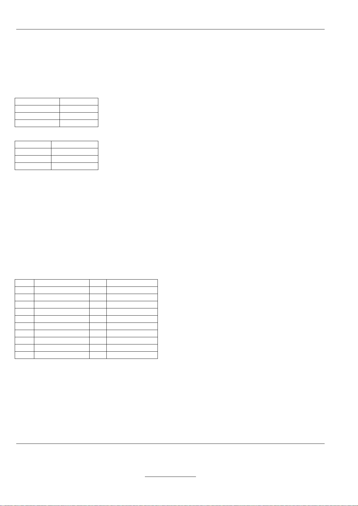
1.1 Ordering information
Order code Features
TMCM-610/SG RS232 interface, USB interface, StallGuard
Page 4
4 TMCM-610
2 The Hardware
2.1 Main technical data
• Supply voltage: DC, 7..28V
• Motor type: bipolar, two-phase stepper motor
• Maximum peak coil current: 1.5A (adjustable by software in 255 steps)
• Interfaces:
• RS232 (default 9600 bps, max. 115200 bps)
• USB 2.0
• eight general purpose outputs (5V, max. 20mA)
• eight general purpose inputs (TTL level), usable as digital or as analog inputs (max. 5V)
• one alarm input (TTL level)
• two stop switch inputs for every motor (TTL level)
• CPU: ATmega64 or ATmega128
• Clock frequency: 16MHz
• Stepper motor controller: two TMC428
• Stepper motor driver: six TMC246 (with StallGuard)
• EEPROM for TMCL program storage: 16kBytes (suitable for up to 2048 TMCL commands)
• Firmware upgrades possible through RS232 or USB interface
• Operating temperature range: 0..70°C
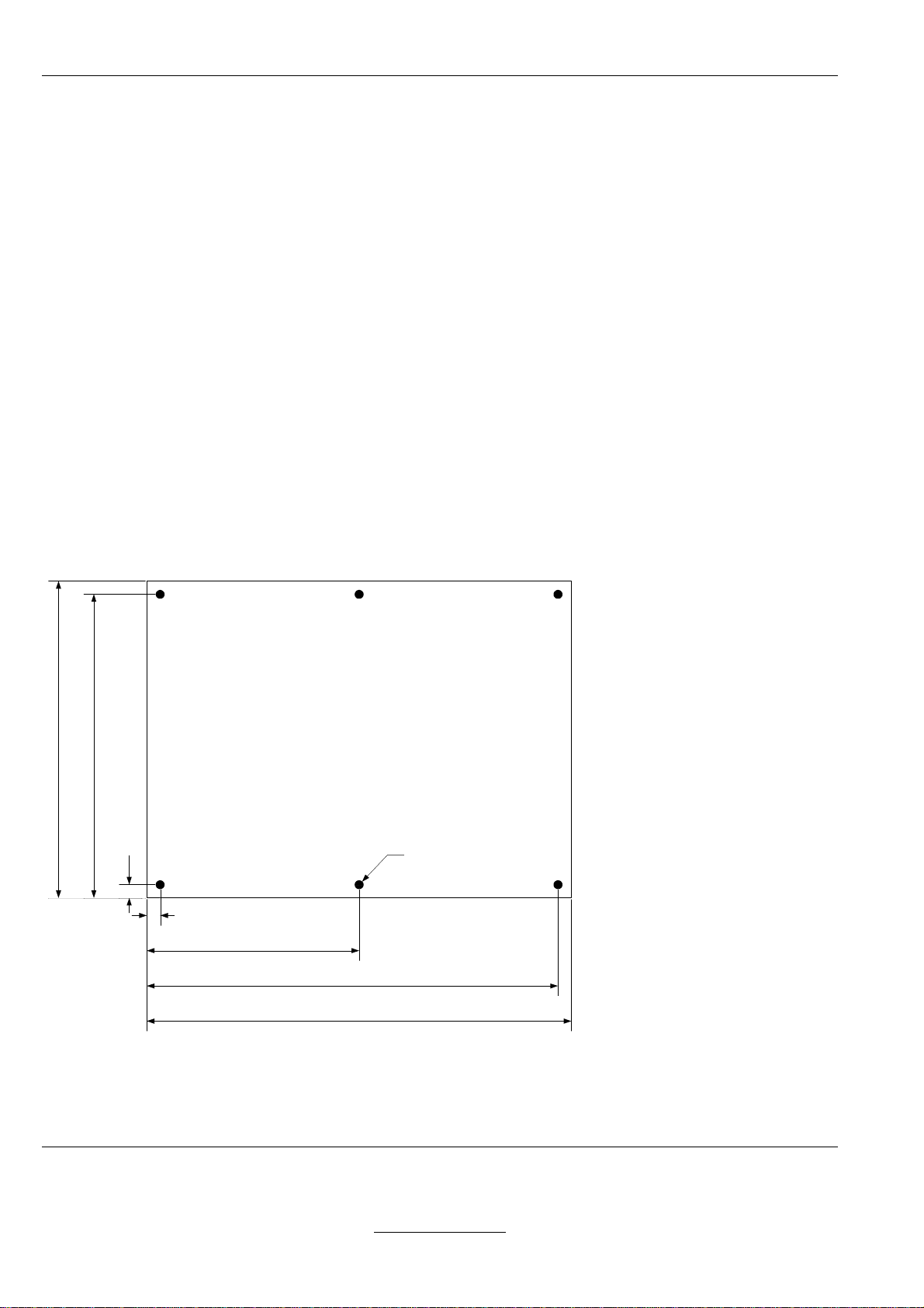
• Dimensions: 160x120mm, please see also Figure 2.1.
115,00
120,00
5,00
5,00
80,00
155,00
160,00
Figure 2.1: Dimensions of the TMCM-610
3,00
Sternstraße 67
D – 20357 Hamburg, Germany
Phone +49-40-51 48 06 - 0
FAX: +49-40-51 48 06 - 60
http://www.trinamic.com
Page 5
TMCM-610 5
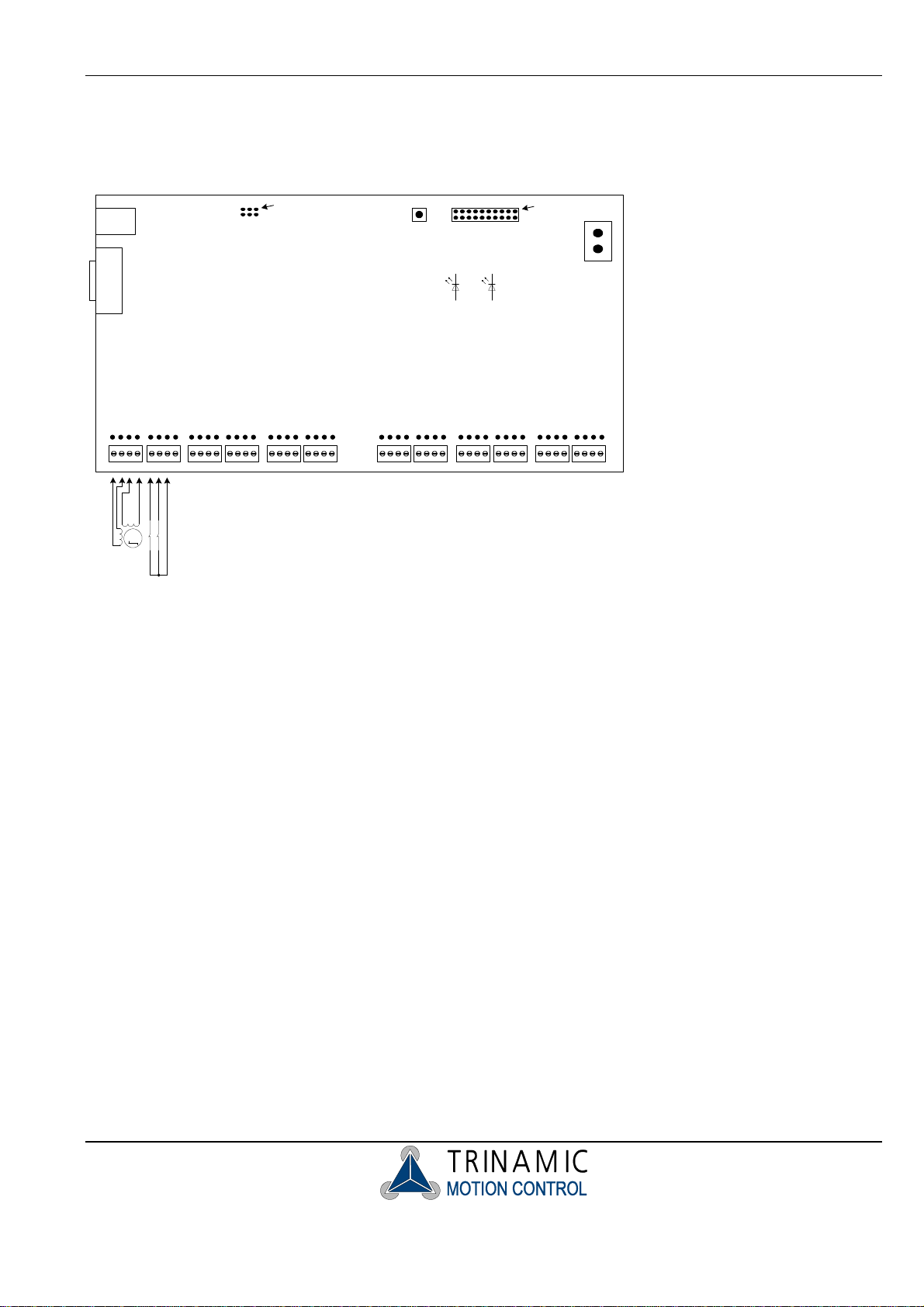
2.2 Connecting the TMCM-610 module
Figure 2.2 gives an overview of all the connectors. The following sections describe all the connectors in detail.
USB
RS232
ISP
Connector
Pin 1
Motor and Stop Switch Connectors / Screw Terminals
Reset
Button
General Purpose
Activity
I/O
Pin 1
GND
+7..28V DC
Power
M
Figure 2.2: Overview of the connectors
2.2.1 Power supply
Connect a power supply of max. 28V DC here (the minimum operating voltage is 7V). The device is protected
against wrong polarity by a diode that shorts the power supply when the polarity is wrong.
2.2.2 LED indicators
There are two LEDs on the board. T he right LED (“P ower”, on a re v. 1.0 board mark ed with “+5V”) lights up when
the unit is powere d. The other LED (“Activit y”, on a rev. 1.0 board mark ed with “D101”) flashes when the unit is
running normally.
2.2.3 Motor connectors
The stepper motors can either be connected to the screw terminals or to the connectors behind the screw
terminals. The p in assignments of the co nnectors are printed on the board. Connect one c oil of the motor to th e
terminals marked “A0” and “A1” and the other coil to the connectors marked “B0” and “B1”. Warning: Never
connect or disconnect a motor w hile the unit is powered! This can damage the mo tor drivers and maybe
also other parts of the unit!
2.2.4 Stop switches / Reference switches
The stop switches can b e connected to the term inals marked “L” and “R” and to the GND terminal. T he switches
are “normally closed” . On the version 1.0 of the board the stop switch connectors are marked wrongly (“L”
and “R” have been interchanged). So, on a version 1.0 board, connect the left stop s witc h to the t er minal marked
with “R” and the right stop switch to the t erm inal m arked with “ L”. T he mark ing will be cor recte d on the nex t versio n
of the board.
Page 6
6 TMCM-610
The reference switc h connec tors also ha ve a “+5V” t erminal. T his is a 5V output that can be used to supp ly photo
couplers or digital hall sensors.
The left stop switch is also used as the reference switch.
2.2.5 RS232 interface
The RS232 interface is one way to connect the unit to a PC or a microcontr oller with RS232 interface. All T MCL
commands can be sen t to the u nit v ia this i nterf ace. A null m odem cable has to b e used t o con nect the T MCM-61 0
to a PC, so the following connections have to be made:
TMCM-610 pin PC pin
2 3
3 2
5 5
The pin assignments of the RS232 socket of the TMCM-610 are as follows:
Pin number Signal name
2 RxD
3 TxD
5 GND
All the other pins of this connector are not connected.
2.2.6 USB interface
The USB interface is a lso a way to connect the unit t o a PC, when higher comm unication speed is needed. T he
interface supports the US B 2.0 standard. P lease see chapter 3. 3 on how to insta ll the device dr iver that is needed
to communicate with the TMCM-610 via USB.
The USB interface and the RS232 interface should not be used simultaneously.
2.2.7 General purpose I/O
The general purpose I/O connec tor prov ides eight d igital outputs and eight in puts that can eith er be used as digital
or as analog inputs with 10 bit accuracy. All digital inputs and outputs operate at TTL level, so the maximum
voltage is 5V. The m aximum current of each digital output is 20m A. The pin assignm ents of the connector are as
follows:
Pin Signal Pin Signal
1 Output 0 2 Output 1
3 Output 2 4 Output 3
5 Output 4 6 Output 5
7 Output 6 8 Output 7
9 Alarm input 10 GND
11 Input 0 12 Input 1
13 Input 2 14 Input 3
15 Input 4 16 Input 5
17 Input 6 18 Input 7
19 +5V (Output) 20 GND
The alarm input also is a d igital input with TTL level and an int ernal pull-up resis tor (the other inputs do not have
internal pull-up res istors as it would not be possible t o use them as analog inputs then). The f unctionality of this
input can be configured (please see the software section for details).
Pin 1 of the connector is shown in figure 2.1. The pins with odd numbers are those near to the edge of the board.
2.2.8 Reset button
Pressing the reset button res ets the micr ocontroller. All m otors are then stopped immediatel y and everything is reinitialized.
Sternstraße 67
D – 20357 Hamburg, Germany
Phone +49-40-51 48 06 - 0
FAX: +49-40-51 48 06 - 60
http://www.trinamic.com
Page 7

TMCM-610 7
2.2.9 ISP connector
This connector is used for two purposes:
• Programming the CPU via an in-circuit progr ammer: This is to be done by Trinamic only and not by the
user! (The user can upgrade the f irm ware via the RS 232 or USB inter face us ing the “ Install OS” f unction i n the
TMCL IDE.)
• Restoring all parameters to their f actor y default valu es: Near l y all par am eters c an be store d in t he EEPROM of
the CPU. If some parameters have been set wrongly this can lead to a case of miss-configuration where the
module can not be reached b y a PC any more. In such circ umstances, all par ameters can be reset to their
factory default values by doing the following:
1. Turn off the power.
2. Link the pins 1 and 3 of the ISP connector with a jumper (as shown in Figure 2.3).
3. Turn on the power and wait until the “Activity” LED flashes fast (much faster than normal).
4. Turn off the power.
5. Remove the link between the pins 1 and 3 of the ISP connector.
6. Turn on the power and wait until the LED flashes normally (this can take some seconds).
Now, all parameters are restored to their factory default values, and the unit should work normally again.
Link these two pins
Pin 1
Figure 2.3: Restoring all parameters to factory default
Page 8

8 TMCM-610
3 Using the TMCM-610
3.1 TMCL
Like most of the other Trinam ic motion c ontrol m odules, the T MCM-610 is also equipped with TMCL, the T rinamic
Motion Control Language. The TMCL lang uage in this unit has b een extend ed so that six m otors can be c ontrolled
with the normal TMCL commands. With a few exceptions, all commands work as described in the “TMCL
Reference and Program ming Manual”. The main dif ference is that the range of the “ Motor” parameter has been
extended to six m otors: its range is now 0.. 5 so that all comm ands that need a m otor number can address all six
motors. All axis parameters can be set independently for each motor.
3.2 Differences in TMCL commands
There are only two commands that are slightly different on the TMCM-610 module. They are as follows:
3.2.1 MVP COORD
The MVP ABS and the MVP REL commands are the same as with the other m odules. With the MVP COORD
command the meaning of the “Motor” parameter is different:
• Moving only one motor: set the “Motor” parameter to the motor number (0..5).
• Moving multiple motors: Set bit 7 of the “Motor” parameter. Now the bits 0..5 of the “Motor” param eter
define which motors are to be started. Each of these bits stands for one motor.
Warning: in the version 6.00 of TMCL for the TMCM-610, t he MVP COORD comm and is not fully implemente d.
This means that when starting multiple motors, the velocities are not calculated so that the motors reach their target
positions at the same time. This will be implemented in the next version.
3.2.2 WAIT RFS
Waiting for the ref erence search of m ultiple motors with th e WAIT RFS comm and is not supported. T he range of
the “motor” param eter is 0..5 (f or the six m otors). To wait for m ultiple referenc e searches , just use one WAIT RF S
command for each motor.
3.3 USB
To make use of the USB inter face, a device dr iver has to be insta lled first. T here is a device dr iver shipped o n the
CD that can be used with W indows 98, Windows M E, Windo ws 2000 and W indows XP. T he device dr iver can not
be used with Windows NT4 and W indows 95 as these operatin g systems do not support USB at all. In m ost Linux
distributions the driver for the USB chip used on the TMCM-610 device (FT245BM) is already included in the
kernel.
When the TMCM-610 module is connected to the USB interface of a PC for the first time, you will be prompted for a
driver by the operating s ystem. Now, insert the CD and s elect the “tmcm- 610.inf” file there. The dr iver will then be
installed and is now ready to be used.
Please note that the TMCM- 610 always needs its own power supp ly and is not powered by the USB bus . So the
module will not be recognized if it is not powered.
To use the USB connection with th e TMCL IDE, at least version 1.31 of the IDE is needed. In t he “Connection”
screen of the “Options” dialog, select “ USB (TMCM-61 0)” and then se lect the m odule in the “Dev ice” list box . Now
all communication between the TMCL IDE and the module uses the USB interface.
To control the TMCM- 610 module form your own PC applic ations the USB version of the “T MCL Wrapper DLL” is
needed.
Sternstraße 67
D – 20357 Hamburg, Germany
Phone +49-40-51 48 06 - 0
FAX: +49-40-51 48 06 - 60
http://www.trinamic.com
 Loading...