

Page 1

MECHATRONIC DRIVES WITH BLDC MOTOR PANdrives
TRINAMIC Motion Control GmbH & Co. KG
Hamburg, Germany
www.trinamic.com
V 1.10
HARDWARE MANUAL
+ +
TMCM-170-57
controller / driver module
up to 10A RMS / 12… 48V DC
CAN, RS232/RS485 (optional)
+ +
+ +
PDx-170-57-E
mechatronic device with
57 mm BLDC servo motor
up to 10A RMS / 12… 48V DC
CAN, RS232/RS485 (0ptional)
incremental encoder
hall sensors
+ +
Page 2

PDx-170-57-E / TMCM-170 Hardware Manual (V1.10 / 2011-NOV-24) 2
Copyright © 2011, TRINAMIC Motion Control GmbH & Co. KG
Contents
1 Life support policy ....................................................................................................................................................... 3
2 Features........................................................................................................................................................................... 4
3 Order codes .................................................................................................................................................................... 5
4 Electrical and mechanical description .................................................................................................................... 6
4.1 Pinning ................................................................................................................................................................... 6
4.2 Application circuit ............................................................................................................................................... 7
4.3 Dimensions ........................................................................................................................................................... 8
4.4 Connectors ............................................................................................................................................................ 9
4.5 PANdrive™ specifications ................................................................................................................................. 9
4.5.1 PANdrive™ motor .................................................................................................................................... 9
5 Operational ratings .................................................................................................................................................... 11
5.1 Power supply requirements........................................................................................................................... 12
5.2 Bus interface ....................................................................................................................................................... 12
5.2.1 Terminating the RS485 network ........................................................................................................ 12
6 Functional description .............................................................................................................................................. 13
6.1 Setting the basic values for operation (using the demonstration application) ............................. 13
6.2 Start-up for encoder based commutation ................................................................................................. 13
6.3 Encoder setting .................................................................................................................................................. 14
6.4 Hall sensor only operation w/o encoder ................................................................................................... 15
6.5 Stop switch ......................................................................................................................................................... 15
6.6 General functions (explore using the Windows based demo software) ......................................... 15
6.7 Temperature, current and voltage monitoring functions ..................................................................... 15
6.8 Programmable motor current limit ............................................................................................................. 16
7 Revision history .......................................................................................................................................................... 17
7.1 Document revision ........................................................................................................................................... 17
7.2 Firmware revision ............................................................................................................................................. 17
8 References .................................................................................................................................................................... 17
9 Appendix ....................................................................................................................................................................... 18
Page 3

PDx-170-57-E / TMCM-170 Hardware Manual (V1.10 / 2011-NOV-24) 3
Copyright © 2011, TRINAMIC Motion Control GmbH & Co. KG
1 Life support policy
TRINAMIC Motion Control GmbH & Co. KG does not
authorize or warrant any of its products for use in life
support systems, without the specific written consent
of TRINAMIC Motion Control GmbH & Co. KG.
Life support systems are equipment intended to
support or sustain life, and whose failure to perform,
when properly used in accordance with instructions
provided, can be reasonably expected to result in
personal injury or death.
© TRINAMIC Motion Control GmbH & Co. KG 20092011
Information given in this data sheet is believed to be
accurate and reliable. However neither responsibility
is assumed for the consequences of its use nor for
any infringement of patents or other rights of third
parties, which may result from its use.
Specifications are subject to change without notice.
Page 4

PDx-170-57-E / TMCM-170 Hardware Manual (V1.10 / 2011-NOV-24) 4
Copyright © 2011, TRINAMIC Motion Control GmbH & Co. KG
2 Features
The PD-170-57 is a combination of an intelligent BLDC servo motor controller / driver, an optical
encoder and a 57mm brushless DC motor. As a controller/driver module the TMCM-170 has been
designed for high performance servo drives based on brushless DC motors. It combines the high
resolution known from stepper motors with the high dynamic, high velocity and high reliability of a
BLDC drive. A build-in ramp generator allows parameterized smooth positioning. Its small form factor
allows direct mounting on / into a motor-encoder assembly. The TMCM-170 supports BLDC motors
with nearly any number of poles and incremental encoders with nearly any resolution. The TMCM-170
integrates a position and a velocity regulator.
The module can be remote controlled via an RS232 or RS485 interface (ordering options) and CAN
interface.
Applications
Replacement of servo drive by high reliability / low cost BLDC drive
Fast and precise positioning
Smooth very low to very high constant / variable velocity drives
Very high velocity stability drives
Extremely compact decentralized motor electronics
Motor / Encoder type
Sine (or block) commutated BLDC motors with encoder and with / without additional hall sensors
Hall sensor based motors can be operated without encoder
Motor power from a few watts to 500W
Motor velocity up to 100,000 RPM (electrical field)
Incremental encoder (2 channel with option for N-channel) with resolution from 256 to 30000 /
motor rotation (opt. per electrical field rotation)
12V to 48V nominal motor voltage
Coil current up to 10A nominal (up to 14A current for short time)
PANdrive™ Motor and Encoder data
Motor: TRINAMICs QBL 5704-94-04-032 or QBL 5704-116-04-042, rated torque 0.32 Nm or 0.42 Nm
Encoder: HEDS-5640-A12 with resolution of 2000 per motor rotation
Please refer to the datasheets for detailed motor and encoder information
Highlights
High-efficiency operation, low power-dissipation
CAN interface and RS232 or RS485 integrated
Integrated Protection: reverse polarity and overload / overtemperature / overvoltage
TRINAMIC TMCL™ protocol and TMCL™ software environment for parameterizing and for update
and for programming of standalone mode
1024 entry 10 bit motor sine commutation table
External (stop) switch or encoder N channel can be used for absolute position reference
Different start up modes for automatic commutation calibration
Page 5

PDx-170-57-E / TMCM-170 Hardware Manual (V1.10 / 2011-NOV-24) 5
Copyright © 2011, TRINAMIC Motion Control GmbH & Co. KG
3 Order codes
The RS232 and RS485 interfaces are assembly options of one and the same TMCM-170 printed circuit
board.
Cables are not included. Add the appropriate cable loom to your order if required.
Order code
Description
Dimensions [mm³]
PD4-170-57-E (-option)
PANdrive™ 0.32Nm
132 x 61 x 61 (without motor axis)
PD5-170-57-E (-option)
PANdrive™ 0.42Nm
152 x 61 x 61 (without motor axis)
TMCM-170 (-option)
BLDC servo module
61 x 61 x 28
Table 3.1: PANdrive™ or module order codes
Option
Host interface
-232
RS232 and CAN interface
-485
RS485 and CAN interface
Table 3.2: Options for order codes
Component parts
Description
TMCM-170-CABLE
Cable loom for module and PANdrive™.
Table 3.3: Order codes for component parts
Page 6

PDx-170-57-E / TMCM-170 Hardware Manual (V1.10 / 2011-NOV-24) 6
Copyright © 2011, TRINAMIC Motion Control GmbH & Co. KG
4 Electrical and mechanical description
4.1 Pinning
Connectors shown as top view
3
2
1
W
V
U
Motor / power supply
connector on bottom PCB
Hall
sensors
1.5mm
conn.
12345
+5V
GNDH1H2
H3
Inter-
face
5
4
3
2
1
RS485- / TXD
RS485+ / RXD
GND
CANL
CANH
Encoder
5
4
3
2
1
CHB
CHA
CHN/Null
GND
+5V
I/O
8
7
6
5
4
+5V
CUR LED
GND
OVT LED
DIRIN
3
2
1 AIN
N.C.
/STOP
21GND
VS
RS485 Term
CAN Term
Figure 4.1: Pinning
Pin
Function
AIN
Analog input: Can measure 0 - 10V signal.
DIRIN
5V TTL input. Not used in current firmware releases
/STOP
Reference Switch / Emergency stop. Tie this pin to GND to stop the motor or to clear
the position counter. Function / polarity depends on Software setting.
(5V TTL input with integrated 10K pull-up resistor to 5V)
OVT LED
5V TTL output: Toggling with 3Hz when temperature pre-warning threshold is
exceeded, high when module shut down due to overtemperature.
CUR LED
5V TTL output: High, when module goes into current limiting mode or into
overvoltage switch off. Toggling with 3Hz on undervoltage condition.
+5V
5V supply for motor hall sensors and as reference for external purpose
GND
Power GND / GND reference
GND is also connected to the mounting holes on the bottom PCB
RXD /
RS485+
RXD signal of module for RS232 communication (RS232 version)
Non-inverting RS485 signal (RS485 version)
TXD /
RS485-
TXD signal of module for RS232 communication (RS232 version)
Inverting RS485 signal (RS485 version)
CANH / CANL
CAN interface signals
U, V, W
BLDC motor coil outputs
CHN
Encoder null channel (optional use)
(5V TTL input with integrated pull-up resistor to 5V)
CHA, CHB
Incremental encoder channel A / channel B
(5V TTL input with integrated pull-up resistor to 5V)
H1, H2, H3
Hall sensor signals
(5V TTL input with integrated pull-up resistor to 5V)
VS
Positive power supply voltage (reverse polarity protected)
Other pins
Leave all other pins unconnected!
Table 4.1: Pinning
Page 7

PDx-170-57-E / TMCM-170 Hardware Manual (V1.10 / 2011-NOV-24) 7
Copyright © 2011, TRINAMIC Motion Control GmbH & Co. KG
I/O board
(top view)
1
2
3
4
5
Interface
1234567
8
I/O
1
2
3
4
5
Hall
sensors
12345
Encoder
Driver board
(top view)
Motor
U V W
Power
+
Interface
EncI/O
Hall
Motor Power
Important note: For the PANdrives™ PD-170, the motor coils, hall sensor signals and encoder signals
are already connected. Nevertheless, in order to connect power supply the upper interface board has
to be removed. Never connect or disconnect the boards while power is switched on!
4.2 Application circuit
The schematic shows a typical application circuit using CAN bus interface. Optionally the unit allows
connection of motor hall sensors and encoder N-channel as well as further digital / analog pins and
different interface options.
TMCM-170
Reference
Sw.
BLDC-
Motor
Encoder
Mech. Axis
GND
/STOP
GND
I/OInterface
CANL
CANH
System's
CAN bus
keep distance
short for CAN
110R
Termination
resistor at bus end
U
V
W
GND
Encoder
+5V
CHA
CHB
VS
GND
Place unit near
encoder / motor
4700µ,
63V
48V system
power
supply
optional overvoltage
suppressor:
high power zener /
zener transistor
circuit
+
-
optional
capacitor if > 2m
CHN
Figure 4.2: Application circuit
Page 8

PDx-170-57-E / TMCM-170 Hardware Manual (V1.10 / 2011-NOV-24) 8
Copyright © 2011, TRINAMIC Motion Control GmbH & Co. KG
4.3 Dimensions
Diameter 61mm, TMCM-170 height 28mm (16mm + highest part), mounting holes diameter is 2.8mm
Figure 4.3: Dimensions of TMCM-170 and PD-170
32,00
25,97
14,50
2
7
,
0
0
13,50
2
7
,
0
0
27,00
30,50
46,77
61,00
Top view of
Driver board
All values are in
millimeters
Gap pad
Metal plate
BLDC
Motor
Encoder
I/O-Board
Driver-Board
PD-170
132,00 (PD4) or 152,00 (PD5)
15,00
1,00
16,00
20,00
39,00
Page 9

PDx-170-57-E / TMCM-170 Hardware Manual (V1.10 / 2011-NOV-24) 9
Copyright © 2011, TRINAMIC Motion Control GmbH & Co. KG
4.4 Connectors
Hall sensor: JST1.5mm type: S5B-ZR-SM2-TF
Other interfaces: JST-PHR – 8 and JST PHR – 5 2.00 mm
4.5 PANdrive™ specifications
This chapter describes the additional components of the PD-170.
4.5.1 PANdrive™ motor
The PD-170 comes either with the QBL 5704-94-04-032 or QBL 5704-116-04-042 motor (ordering option).
For further information refer to the QBL 5704 motor manual, also.
Main characteristics:
Hall Effect Angle: 120° electric angle
Shaft run out: 0,025 mm
Insulation Class: B
Radial Play: 0,02 mm 450G load
Max Radial Force: 75N (10mm from flange)
Max Axial Force: 15N
Dielectric Strength: 500 VDC For One Minute
Insulation Resistance: 100M Ohm min. 500VDC
Recommended Ambient Temp.: -20 to +40°C
Bearing: Brushless motors fitted with ball bearings
Specifications
QBL 5704
-94-04-032
-116-04-042
No. of Pole
4 4
No. of Phase
3 3
Rated Voltage
V
36
36
Rated Phase Current
A
5.08
6.67
Rated Speed
RPM
4000
4000
Rated Torque
Nm
0.32
0.42
Max Peak Torque
Nm
0.98
1.3
Torque Constant
Nm/A
0.063
0.063
Line to Line Resistance
Ohm
0.45
0.35
Line to Line Inductance
mH
1.4
1
Max Peak Current
A
16.5
20.5
Lenth (L
MAX
)
mm
94
116
Rotor Inertia
kgm² x 10-6
17,3
23
Mass
kg 1 1,25
Related TRINAMIC PANdrive™
PD4-170-57
PD5-170-57
Table 4.2: Motor technical data
Page 10

PDx-170-57-E / TMCM-170 Hardware Manual (V1.10 / 2011-NOV-24) 10
Copyright © 2011, TRINAMIC Motion Control GmbH & Co. KG
Adjustments for QBL5704-116-04-042
Switch the reverse hall sensor polarity on and the reverse encoder direction off. Use the basic control
and diagnostics software or TMCL-IDE.
Adjustments for QBL5704-94-04-032
Switch the reverse hall sensor polarity off and the reverse encoder direction on. Use the basic control
and diagnostics software or TMCL-IDE.
Figure 4.4: Motor dimensions
Page 11

PDx-170-57-E / TMCM-170 Hardware Manual (V1.10 / 2011-NOV-24) 11
Copyright © 2011, TRINAMIC Motion Control GmbH & Co. KG
5 Operational ratings
The operational ratings show the intended / the characteristic range for the values and should be
used as design values. An operation within the limiting values is possible, but shall not be used for
extended periods, because the unit life time may be shortened. In no case shall the limiting values be
exceeded.
Symbol
Parameter
Min
Typ
Max
Unit
VS
Power supply voltage for operation
12.5
14 - 48
52
V
V
SMAX
Maximum power supply voltage (for surge)
60
V
V
SLOOFF
Under voltage switch off trip point
9.5
10
10.5
V
V
SON
Under voltage switch on trip point
10.5
12
12.5
V
V
SOFF
Over voltage switch off trip point (Feature can be
switched off, then V
SMAX
limit applies)
52
55
58
V
VSD
Power supply voltage for module operation with motor
disabled
7 8 9.5
V
IS
Power supply current
0.04
(P
Motor
+3..10W)
/ VS
I
MOT
A
PID
Module idle power consumption without encoder / hall
sensor
2.4 W
V5
5 Volt (+-4%) output external load (encoder plus hall
sensors plus other load)
0 200
mA
IMC
Continuous Motor RMS current
(module surface at maximum 85°C)
10
A
IMP
Short time Motor current in acceleration periods
It is not recommended to set motor current above 12A!
14
A
I
MPP
Peak coil output current for 100ms
40
A
f
CHOP
Chopper frequency
20
kHz
T
SL
Motor output slope (U, V, W)
100 ns
VI
Logic input voltage on digital inputs, encoder and hall
sensor inputs
-0.3 VCC+
0.3
V
II
Pull-up resistor current for hall and encoder inputs
50
250
400
µA
VO
Logic output current on digital outputs (5V CMOS output)
10
mA
VIA
Analog input voltage
-24
0 – 10
24
V
EV
Exactness of voltage measurement
-5 +5
%
EC
Exactness of current measurement (the measured coil
current value might not correspond to the RMS current,
but is repeatable within the given exactness)
-10 +10
%
f
ENC
Encoder count rate (signals 50% duty cycle)
13.3
MHz
TO
Environment temperature operating
-25 +85
°C
T
board
Temperature of the bottom (driver) PCB, as measured by
the integrated sensor.
<105
115
°C
Table 5.1: Operational ratings
Page 12

PDx-170-57-E / TMCM-170 Hardware Manual (V1.10 / 2011-NOV-24) 12
Copyright © 2011, TRINAMIC Motion Control GmbH & Co. KG
5.1 Power supply requirements
The power supply should be designed in a way, that it supplies the nominal motor voltage at the
desired maximum motor power. In no case shall the supply value exceed the upper / lower voltage
limit. The BLDC motor unit uses a chopper principle, i.e. the power supply to the motor is pulsed at a
frequency of 20kHz. To ensure reliable operation of the unit, the power supply has to have a sufficient
output capacitor and the supply cables should have a low resistance, so that the chopper operation
does not lead to an increased power supply ripple directly at the unit. Power supply ripple due to the
chopper operation should be kept at a maximum of a few 100mV.
Therefore we recommend to
˗ keep power supply cables as short as possible
˗ use large diameter for power supply cables
˗ if the distance to the power supply is large (i.e. more than 2-3m), use a robust 4700µF or
larger additional filtering capacitor located near to the motor driver unit.
An effect the power supply has to cope with, is, that the motor can feed back substantial current into
the power supply whenever it is actively braked! While this generally is a positive effect (because it
saves energy), precautions have to be taken, to limit the supply voltage to within the operational
limits. The TMCM-170 contains an overvoltage protection circuit, which disables braking whenever the
upper supply voltage limit is exceeded. This automatic function may lead to an unwanted behavior,
i.e. overshooting the target position, and thus can be disabled. Disabling the overvoltage protection
should only be done, provided that the user takes additional precautions to limit the voltage:
It is recommended to use
a) a large capacitor on the power supply lines able to store substantial part of feed back energy
b) a zener / suppressor diode circuitry, limiting the power supply voltage to a maximum of 52-
60V
5.2 Bus interface
The TMCM-170 supports an optional CAN interface. It can be operated via CAN or RS232 / RS485 in the
same way. CAN bus and RS485 require a termination resistor at both ends of the cable (but not at
every unit). This resistor is integrated and can be activated on the TMCM-170 by shorting a soldering
bridge (dotted line in the connector drawing), but for most purposes it is more elegant to provide
this resistor external to the unit.
5.2.1 Terminating the RS485 network
For RS485 in addition to the termination resistor a termination network is required, which forces an
“inactive” level to the line, when no driver is on. Typically, use a 1K resistor to + 5V for RS485+ line
and a 1K resistor to GND for the RS485- line at some point of the network.
Page 13

PDx-170-57-E / TMCM-170 Hardware Manual (V1.10 / 2011-NOV-24) 13
Copyright © 2011, TRINAMIC Motion Control GmbH & Co. KG
6 Functional description
6.1 Setting the basic values for operation (using the
demonstration application)
The TMCM-170 can use nearly any BLDC motor and encoder type. However, care has to be taken to
correctly set the motor pole count (default: 8) and encoder resolution (default: 4096) and direction
(default: Encoder gives same direction as motor) before trying to operate the motor! Using a
PANdrive™ motor please refer to chapter 3.5.1. This motor comes normally with the encoder HEDS5640-A12, in this case the encoder resolution is 2000. Please note the TMCL-code in the appendix at
the end of this document.
If a hall sensor is used, please check if the hall sensor polarity is to be reversed (try operating the
motor in block commutation mode, first). Also choose a fitting initialization mode (2 is most
universal) and set the corresponding parameters (please see chapter on start up).
The motor behavior afterwards may still give unsatisfactory results: The next step is to tune the PID
parameters.
For these basic settings, the Windows based demonstration application can be used. It requires
connection to the RS232 interface or via an RS485 converter to the RS485 interface. For RS485, as a
first step use the TMCL-IDE to set the parameter “Telegram pause time” to a value of about 20. Further
basic settings are required for motor start up (see next chapter).
To avoid motor operation or damage before the unit is completely parameterized, use a supply
voltage of only 8V! This disables the motor.
6.2 Start-up for encoder based commutation
The TMCM-170 uses an incremental encoder for motor commutation. Incremental means, that the
encoder does not give an absolute position reference. Thus, the unit needs an internal start up
procedure, which determines the encoder position with respect to the actual pole motor orientation.
The TMCM-170 provides basically two modes for encoder initialization:
Mode 0 uses additional motor hall sensors for the start up phase. Therefore, the motor can not do a
precise positioning until it has done at least one electrical rotation. This can be perceived
by a somehow rough behavior on the first positioning run.
We recommend using this mode, when the motor has hall sensors and mode 1 does not
give reliable results.
However, the motor hall sensors typically are not as precise, as this would be desired for
sine commutation. To accomplish with the hall sensor error and hysteresis, you can set the
corresponding parameters “Init Sine Block Offset CW” and CCW.
Mode 1 drives the motor field into a known position and then evaluates the encoder position.
While this is a very precise scheme, it is susceptible to external force applied to the rotor:
The rotor is not to be blocked in any direction. Additionally external mechanical torque
applied to the axis should be kept low. To use this mode, it is important to set the “Sine
Initialization Current A” as high as possible (within the 14A limit). Default value is 11A. You
can set Sine Initialization Current B to a somewhat lower value (at least ½ of Current A) to
give optimum results. The best setting has do be determined for a given motor. To allow
for minimum motor movement upon initialization, this mode also checks the hall sensor
positions.
Mode 2 is the same as mode 1, but does not check if the motor has hall sensors.
Mode 3 is the most precise and reliable initialization mode: It uses the encoder N-channel for
initialization. To first find the N-channel reference position, the motor is turned by up to
one rotation, until the N-channel is found positive. The velocity and direction can be
specified using the parameter “Sine Init Velocity”. After finding the reference position, the
Page 14
PDx-170-57-E / TMCM-170 Hardware Manual (V1.10 / 2011-NOV-24) 14
Copyright © 2011, TRINAMIC Motion Control GmbH & Co. KG
“Actual Commutation Offset” gives the angular relationship between motor and encoder.
Therefore this parameter has to be stored correctly in EEPROM before power on! Do not
enable this mode, before the parameter has been set correctly. Mode 4 helps for the very
first initialization of this mode.
Mode 4 helps to do a first initialization and tuning of mode 3. It searches for the N-channel
reference point first, and then does a mode 2 initialization to determine the correct setting
for the “Actual Commutation Offset”. The encoder N-channel polarity has to be high active
for this mode (the actual setting of the encoder null polarity has no influence in this mode),
and, additionally, you have to specify the polarity of the encoder A- and B-channel upon N-
channel activity using the setting “Encoder Null Polarity”, bits 1 and 2. The correct setting of
this depends on the encoder. If the N-channel referencing fails, the motor does two full
rotations and then stops. Try again with reversing the “Encoder Null Polarity”. After
successfully initializing the “Actual Commutation Offset”, you can try moving the motor and
tune the offset, if desired. Then store the offset and switch to mode 3. If any encoder errors
are flagged during operation of the motor, retry with a modified setting for A- and Bchannel polarity.
Attention: Initialization modes 1 to 4 apply a high current to the motor for a few seconds. Be sure
to parameterize the initialization current correctly (i.e. not more than 2* the maximum
rated motor current) before first powering on the unit.
The quality of the initialization phase result can be checked by rotating the motor left and right at the
maximum velocity (use a velocity setting slightly higher than the motor can follow). Maximum velocity
for left and right direction shall not differ by more than a few percent. Also make some checks if
results are reproducible.
Whenever changing one of these parameters, re-power the unit to restart initialization phase!
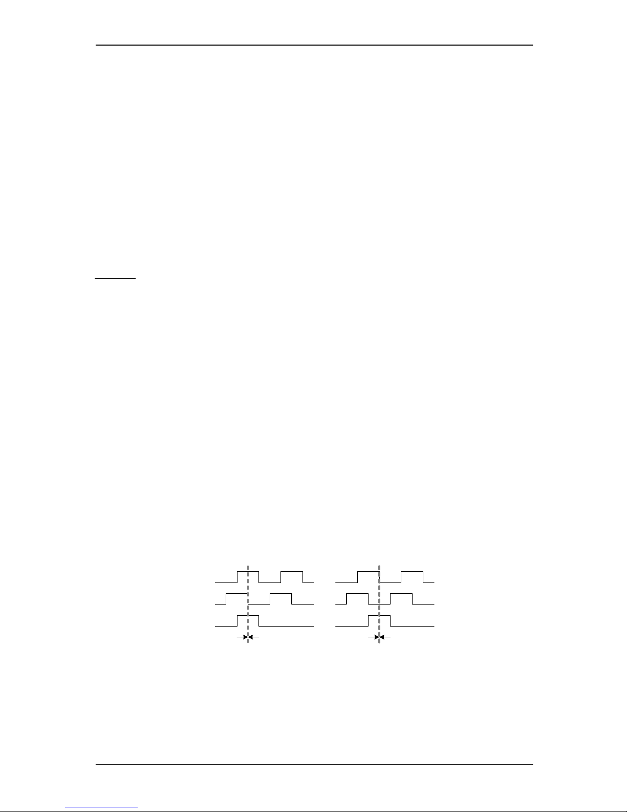
6.3 Encoder setting
The N-channel (index channel) of the encoder is not required for motor operation, but it is very good
for motor initialization, because it gives an absolute and exact reference point. So, the motor
initialization modes 3 and 4 use the N-channel for motor initialization. Behavior of the N-channel
signal is very dependent on the encoder type and has to be taken into account for the setting of the
TMCM170 encoder interface. Please refer to the following figure for correct setting of the Encoder Null
Polarity flag.
A wrong setting may either hinder the module from initializing the sine mode, or might lead to the
Encoder Error flag being set, in spite of correct encoder function.
zero event
Enc-A
Enc-B
Enc-N
(index)
Set Encoder Null
Polarity to
binary 011
Set Encoder Null
Polarity to
binary 001
zero event
CW turn CCW turn CW turn CCW turn
0
1 0
0
Page 15

PDx-170-57-E / TMCM-170 Hardware Manual (V1.10 / 2011-NOV-24) 15
Copyright © 2011, TRINAMIC Motion Control GmbH & Co. KG
6.4 Hall sensor only operation w/o encoder
The module can be used without an encoder. In this case, set the encoder resolution parameter (SGP
250) to the hall sensor resolution, i.e. 3 times the number of motor poles. Example: For a 4 pole
motor set the encoder resolution to 12. To avoid oscillations in positioning mode, the algorithm in
this mode stops regulation, as soon as the target distance is below the setting as determined by
“MVP target reached distance”. Adapt this setting to your needs. Switch the module to hall sensor
based commutation permanently in order to skip encoder initialization procedure in this configuration.
Please be aware, that the hall sensor resolution is very low, when compared to an encoder, and thus,
the PID regulator parameterization values have to be set much higher than the default setting.
Without encoder, the velocity measurement is not available. You may want to set a lower value than
the default for the “PWM Hysteresis” setting to get a softer response upon target reaching.
6.5 Stop switch
For positioning applications, typically some kind of global initialization is required. This can either be
done via a central unit operating the motor via its bus interface, or a reference switch can be
connected to the stop input (pull down to 0V at reference point). The position counter can be
automatically cleared when this point is reached. Be careful not to apply a voltage different from GND
to this digital input!
6.6 General functions (explore using the Windows based
demo software)
The TMCM-170 module can either be remote controlled via the PC demonstration software or a user
specific program. The function of the standalone mode can be modified by the user by writing
initialization values to the on-board EEPROM, e.g. a maximum rotation velocity, motor current limit
and rotation direction.
For more detailed software information refer to the TMCM-170 Module – Reference and
Programming Manual.
6.7 Temperature, current and voltage monitoring functions
LED output
Action
Meaning
Current limit
Blink
The current limit LED blinks upon under voltage switch off
Current limit
On / Flicker
Motor PWM is reduced due to exceeding the set motor current limit
or overvoltage threshold is exceeded
Temperature
warning
Blink
The power stage on the module has exceeded a critical temperature
of 85°C. (Pre-warning)
Temperature
warning
On
The power stage on the module has exceeded a critical temperature
of 115°C. The motor becomes switched off, until temperature falls
below 105°C. The measurement is correct to about +/-10°C
Table 6.1: LED outputs
Page 16

PDx-170-57-E / TMCM-170 Hardware Manual (V1.10 / 2011-NOV-24) 16
Copyright © 2011, TRINAMIC Motion Control GmbH & Co. KG
6.8 Programmable motor current limit
The motor current limiting function is meant as a function for torque limiting, and for protection of
motor, power supply and mechanical load.
Whenever the pre-programmed motor current is exceeded in a chopper cycle, the TMCM-170 calculates
a reduced PWM value for the next chopper cycle. New values are calculated 1000 times a second. The
response time of the current regulation can be set using the parameter “current regulation loop
delay”:
A value of zero means, that in every 1kHz period, the current correction calculation is directly executed
and the resulting PWM value is taken. A higher current loop delay acts like a filter for the current. The
higher the value of the delay the slower is the current loop response time. A value of 10 (default)
leads to a current regulation response time of about 10 ms for an 1/e response. On the mechanical
side a higher value simulates a higher dynamic mass of the motor.
The actual current regulation time may differ depending on the PID settings.
Attention: Please be careful, when programming a high value into the current regulation loop delay
register: The motor current could reach a very high peak value upon mechanical blocking
of the motor. The same goes for the motor current limit value: do not set higher than
12A if you are not sure about this.
If the short time motor coil current is not limited to a maximum of about 40A, this could
destroy the unit.
There are a number of aspects when using the current limiting function:
The current measurement is done at a point of the chopper cycle, where just one coil is switched
on. When using sine commutation, the effective coil current is about 88% of the measured current
respectively of the current limit setting.
The current measurement cannot detect currents below about 200-300mA. If the current limit is
set to a too low value, the motor may operate spuriously or become continuously switched off.
The current limiting function is not meant as a protection against a hard short circuit.
The performance of the current limiting depends on the motor and on the commutation mode.
Especially in sine commutation mode, the measured current and thus current limiting may be
quite instable. The current limit should be programmed to a value high enough, in order to
achieve good positioning and acceleration performance.
Operation of the current limiter and the PID regulator may result in instable behavior, if the
motor gets into a resonance area. Try adapting the current regulation loop delay parameter.
If the motor is blocked and the ramp generator is not stopped, the motor will speed up and try
to catch up with the ramp generator position after removal of the blocking. To control this effect,
you can set the parameter Clear Target Distance in order to stop the ramp generator, when the
deviation between the positions becomes too large. The effect of this may look somehow weird
if the user does not expect it.
Page 17

PDx-170-57-E / TMCM-170 Hardware Manual (V1.10 / 2011-NOV-24) 17
Copyright © 2011, TRINAMIC Motion Control GmbH & Co. KG
7 Revision history
7.1 Document revision
Version
Comment
Author
Description
1.00
2005 – 2007
Dw
Initial Versions
1.05
05-09-2007
HC
Added Documentation Revision and PANdrive™ information
1.06
10-09-2007
GE
Update of dimensions and pictures
1.07
30-10-2007
HC
Encoder graphics added (chapter 6.3)
1.08
21-11-2007
HC
PANdrive™ encoder resolution info corrected to 2000 per
rotation
1.09
10-12-2007
MJ
Chapter v5.1 extended; Appendix with TMCL-code
1.10
2011-NOV-24
SD
New order codes, new front page, minor changes
Table 7.1: Document revision
7.2 Firmware revision
Version
Comment
Description
0.90
Initial Version
Attention: Use Documentation V0.90 or later for connector pinning!!!
0.92
First release
Added encoder N-channel initialization
0.93 Added encoder N-channel for automatic correction and encoder error
flag
0.94 Allows specifying of CHA and CHB polarity for nulling of encoder –
uses higher bits of Encoder Null Polarity
1.00
Release 1.0
Added operation mode with hall sensors only.
1.01 Corrected RS485 behavior
1.02 Added standalone mode feature
1.03 Fixed RS485 delay problem (master had to wait for timeout time before
sending new command), when multiple units share a bus
1.07
TMCL
Added TMCL™ standalone program capability, extended command set
for TMCL™. Up to 64 commands can be stored in EEPROM.
Table 7.2: Firmware revision
8 References
[TMCL]
TMCL™ Manual, www.trinamic.com
[TMCM –170]
Reference and Programming Manual, www.trinamic.com
QBL5704 Manual
QBL5704 BLDC servo motor manual, www.trinamic.com
HEDS-5640#A12 info
HEDS-5640#A12 encoder information http://www.avagotech.com
Page 18

PDx-170-57-E / TMCM-170 Hardware Manual (V1.10 / 2011-NOV-24) 18
Copyright © 2011, TRINAMIC Motion Control GmbH & Co. KG
9 Appendix
// Initialization PANdrive PD4/PD5-170
// --> Start this initialization procedure, when the initialization
// parameters have been lost, e.g. due to Firmware upgrade <-// please see manual, if values have to be modified, e.g. due to power supply
// current limitation
// Set Parameter
MST 0
SGP 247, 0, 40 //Initialization Sinus Current A
SGP 248, 0, 35 //Initialization Sinus Current B
SGP 253, 0, 4 //Motor Pole = 4
SGP 254, 0, 0 //Hall Sensor Invert PD4
// SGP 254, 0, 1 //Hall Sensor Invert PD5
SGP 250, 0, 2000 //Encoder Steps per Rotation
SGP 252, 0, 1 //Reverse Encoder Null Polarity
SGP 251, 0, 1 //Reverse Encoder Direction PD4
// SGP 251, 0, 0 //Reverse Encoder Direction PD5
SGP 249, 0, 4 //Init Mode 4
SAP 159, 0, 1 //Commutation Mode 1 = Sinus / 0 = Block
SAP 160, 0, 1 //Start Initialization
SAP 4, 0, 3000 //max. Pos. Velocity
ROR 0, 0
A: GAP 160, 0 //Ready
COMP 1
JC NE, A
SAP 6, 0, 100 //Max. Current
SAP 11, 0, 2000 //Acceleration
SAP 146, 0, 1 //Use Velocity PID
// Store Parameter
STAP 6, 0 //Store Max Current
STAP 4, 0 //Store Max Pos. Velocity
STAP 165, 0 //Store Commutation Offset !
SGP 249, 0, 3 //Init Mode 3 ( N-Kanal )
STOP
 Loading...