

Page 1

SIXpack 2
Manual
6-Axis stepper motor controller / driver module
1.4A RMS (2A peak) / 48V
with CAN, RS485 and RS232 interface
Manual Version: 1.01
May 5
th
, 2006
GmbH & Co KG
Sternstraße 67
D - 20357 Hamburg, Germany
Phone +49-40-51 48 06 - 0
FAX: +49-40-51 48 06 - 60
http://www.trinamic.com
Page 2

SIXpack 2 – manual (V1.01 / May 5th, 2006) 2
Table of Contents:
1 Life support policy.............................................................................................. 4
2 Introduction......................................................................................................... 5
2.1 Brief Description.......................................................................................................... 5
2.2 What do I have to know about my application ............................................................5
2.2.1 The SIXpack 2 does not support............................................................................ 5
2.3 Technical Data............................................................................................................ 6
3 System Start Up.................................................................................................. 7
3.1 System Start Up / Notes .............................................................................................7
3.2 Selecting Motors ......................................................................................................... 7
3.3 Length of Wires........................................................................................................... 7
3.4 Grounding ................................................................................................................... 7
3.5 Improvement of the EMC-Conduction......................................................................... 7
3.6 Further Information: ....................................................................................................7
4 Replacing QUADpack or SIXpack...................................................................... 8
4.1 DIP-switch marking comments ................................................................................... 8
4.2 SIXpack compatible setting......................................................................................... 8
4.3 QUADpack compatible setting.................................................................................... 8
5 Fundamental Functions – First Steps............................................................... 9
5.1 Security Advise ........................................................................................................... 9
5.2 Basic Device Settings ................................................................................................. 9
5.2.1 SIXpack 2 Address................................................................................................. 9
5.2.2 Option RS232/RS485............................................................................................. 9
5.2.3 Baudrate of serial interface ..................................................................................10
5.2.4 Termination of CAN/RS485.................................................................................. 10
5.2.5 Seven-segment display ........................................................................................ 10
5.2.6 Driver enable ........................................................................................................ 10
5.2.7 Adjusting the maximum current............................................................................ 11
5.2.8 Adjusting chopper mode....................................................................................... 12
5.3 Connections.............................................................................................................. 12
5.3.1 Current supply...................................................................................................... 12
5.3.2 Serial interface .....................................................................................................12
5.3.3 Motor connectors.................................................................................................. 12
5.3.4 Connector specifications ...................................................................................... 13
5.4 Start-up with software SQPack ................................................................................. 14
5.4.1 Installation ............................................................................................................ 14
5.4.2 Initiation................................................................................................................ 14
5.4.3 Functional test: Get system information of SIXpack 2.......................................... 14
5.4.4 “First steps”: Movement of motor ......................................................................... 14
5.4.5 Concept of SIXpack 2 interface protocol.............................................................. 14
5.4.6 Macro functions of SQPack.................................................................................. 15
5.5 Operation with reference/ending points .................................................................... 15
5.5.1 Types of reference point definitions .....................................................................16
5.5.2 Hardware installation............................................................................................ 16
5.5.3 Reference search software configuration............................................................. 17
5.6 Basic configurations for operation............................................................................. 18
5.6.1 Adjusting motor current ........................................................................................ 18
5.6.2 Configuration of acceleration and velocity............................................................ 19
5.6.3 Motion control....................................................................................................... 19
6 Full Functionality.............................................................................................. 20
6.1 Inputs and Outputs.................................................................................................... 20
6.1.1 RS232 or RS485 interface ...................................................................................20
6.1.2 CAN interface ....................................................................................................... 20
6.1.3 Ready output ........................................................................................................ 20
6.1.4 Multifunctional connector “RS232” ....................................................................... 20
6.1.5 RS 232-Remote Control via CAN-Interface.......................................................... 21
6.2 Programming ............................................................................................................22
Page 3

SIXpack 2 – manual (V1.01 / May 5th, 2006) 3
6.2.1
Hints for Programming ......................................................................................... 22
6.2.2 Examples.............................................................................................................. 24
6.3 Adjusting SIXpack 2 to motors micro step characteristics ........................................ 27
6.3.1 Calculation of micro step frequency ..................................................................... 27
6.3.2 Adapting the microstep-table to the motor characteristics ................................... 28
6.4 Reference point adjustments .................................................................................... 28
6.4.1 Coordinate plane of an axis.................................................................................. 28
6.4.2 Reference point / reference switch....................................................................... 28
6.4.3 Moving zero-point................................................................................................. 28
6.4.4 Automatic reference search .................................................................................29
6.4.5 Adjusting activity zone of reference switch........................................................... 29
6.4.6 Compensation of reference switch delay .............................................................29
6.4.7 Elimination of glitches........................................................................................... 29
6.4.8 Adjusting reference search velocity...................................................................... 29
6.4.9 Aborting reference search.................................................................................... 29
6.5 End switch configurations ......................................................................................... 30
6.5.1 A_ln as end switch input....................................................................................... 30
6.5.2 Combination of end and reference switches ........................................................ 30
6.5.3 “Security Margin” for combined end/reference switch .......................................... 30
6.6 Commands for axis movements ............................................................................... 31
6.6.1 Basic ramp run ..................................................................................................... 31
6.6.2 Start of constant rotation ...................................................................................... 31
6.6.3 Change target position for ramp run..................................................................... 31
6.6.4 Starting different motors synchronous.................................................................. 31
6.6.5 Starting linear interpolation of multiple axis.......................................................... 32
6.6.6 Configuration for rotating movements .................................................................. 32
6.7 Control of motor current............................................................................................ 33
6.8 Default values ........................................................................................................... 34
7 Instruction Set................................................................................................... 35
7.1 Setting motor parameters .........................................................................................35
7.2 Driving Ramps ..........................................................................................................39
7.3 Additional Inputs / Outputs........................................................................................ 42
7.4 Other Settings........................................................................................................... 43
7.5 Multi-dimensional Movement .................................................................................... 44
7.6 Service-Functions ..................................................................................................... 44
8 Instruction table................................................................................................ 47
9 Test Reports...................................................................................................... 48
Page 4

SIXpack 2 – manual (V1.01 / May 5th, 2006) 4
1 Life support policy
TRINAMIC Motion Control GmbH & Co. KG does not
authorize or warrant any of its products for use in life support
systems, without the specific written consent of TRINAMIC
Motion Control GmbH & Co. KG.
Life support systems are equipment intended to support or
sustain life, and whose failure to perform, when properly
used in accordance with instructions provided, can be
reasonably expected to result in personal injury or death.
© TRINAMIC Motion Control GmbH & Co. KG 2005
Information given in this data sheet is believed to be
accurate and reliable. However no responsibility is assumed
for the consequences of its use nor for any infringement of
patents or other rights of third parties, which may result form
its use.
Specifications subject to change without notice.
Page 5

SIXpack 2 – manual (V1.01 / May 5th, 2006) 5
2 Introduction
2.1 Brief Description
The SIXpack 2 is a highly integrated stepper motor controller for six 2-phase stepper motors with a coil
current of up to 2000 mA each. It is the fully compatible advancement of the QUADpack and SIXpack
with enhanced ratings and functions.
The SIXpack 2 comes in a rugged box package with tested electromagnetic compatibility. It is easy to
use and the ideal solution for stepper motor control in an industrial environment.
A DSP supported by special hardware allows a powerful function set and a wide stepping frequency
range for all motors. The SIXpack 2 is equipped with RS 232, RS 485 and CAN-Interface.
2.2 What do I have to know about my application
Before the SIXpack 2 is set up the demands of the application to the stepper motors should be clearly
defined.
What are the right motors? The SIXpack 2 supports 2-phase stepper motors. The peak motor power is
defined by the modules supply voltage and the coil current of the driver ICs (max. 2000mA).
The actual motor position is not known after power on. Thus a reference search has to be made in order
to find the absolute position. Most applications use switches or photo interrupters to detect the reference
position. In some applications a mechanical limit point without any detector switch is appropriate. The
SIXpack 2 does not support encoders.
To control the SIXpack 2 there are different interfaces (RS232, RS485, CAN). It is not relevant to the
SIXpack 2 if it is controlled by a desktop-PC, another machine operating unit or a set up with
microcontroller. A stand alone operation is not possible.
2.2.1 The SIXpack 2 does not support
Stand alone operation: The SIXpack 2 can not operate without initialization and control by a host
connected to one of its serial interfaces.
Closed loop operation: The SIXpack 2 has no encoder interface and there is no other possibility for
nominal/actual value comparison for motor position. It is possible to
compare the internal position counter with the status of the reference
switch. If an invalid value is detected an automatic reference search can be
started automatically.
External output stages: There is no possibility to connect external power stages to the SIXpack 2 to
increase the maximum motor rating above 2A / 48V.
Page 6

SIXpack 2 – manual (V1.01 / May 5th, 2006) 6
2.3 Technical Data
ramp profile: automatic 3-phase ramps (32 Bit signed position resolution) with
programmable parameters for maximum frequency and acceleration for
each channel; alternatively user defined ramps; automatic reference search
(reference switch)
stepping frequency: full step frequencies from 0.3 Hz 12.5 kHz
step type: microstepping resolution 1/16 with user-programmable motor
characteristics or sine-table
current control: programmable acceleration-dependent motor current; programmable stand-
by timer for current reduction
interfaces: RS 232 or RS 485; CAN
protocols: 9 byte control, barcode-reader interface via RS 232 in CAN-mode possible
I/O-lines: 10 bit analogue input for ratiometric measurements or stop functions; digital
input for reference switch; separate analogue input; digital I/O and digital
output; LED-„Interface active“; 7-segment display (number of active motors,
Decimal point indicates reference search); 1 Ready Output (Open
Collector)
power supply: 15 to 48 V DC (absolute max. 58V)
max. ca. 12A, depending on motor type
motor current SIXpack: software configurable ca. 100 - 2000 mA per channel (peak coil current);
constant current (chopper, ca. 36 kHz), motor driver thermally protected
motor type: bipolar 2-phase motors
motor connectors: 8-pin single-in-line (motor, reference switch, A/D, 5V supply (15 mA))
temperature range: up to 85°C with reduced current or forced cooling of board
dimensions: board: W: 126, D: 180, H: 25 mm; housing: W: 152, D: 180, H: 36 mm
Feature SIXpack 2 data Advantages of new feature
Supply voltage (nominal)
Supply voltage (maximum limit)
Motor current
Numbers of motors
Chopper scheme
Motor drivers
Software
Control LEDs
Reset button
Protection
Hot plugging / emergency off
15 .. 48 VDC
10 .. 58 VDC
Software setting 0.2A to 1.4A RMS
6
Slow Decay / Mixed Decay
TMC239A-LA Very low power dissipation and high reliability
Fully compatible to SIX/QUADpack
Data, Reset, +5V
Yes
Varistor protection for all motors Life plug protection up to some degree
Additional motor off-jumper
High motor dynamics / higher torque
(up to 3x compared to SIXpack)
Reduced motor resonances at medium velocities and
improved microstep exactness when using Mixed Decay
Not visible by software – connect to TTLIO1 if software
readout is desired
Page 7

SIXpack 2 – manual (V1.01 / May 5th, 2006) 7
3 System Start Up
3.1 System Start Up / Notes
When the SIXpack 2 is supplied with power it runs an internal initialization and a self-test of the internal
processor-system starts. If executed successfully a “0“ appears in the LED-display after a second. The
SIXpack 2 is operational now and can receive user commands.
Defective motor drivers can not be detected by the self test. Should the motor turn on and off during
operation, a constant high motor current or insufficient cooling of the drivers could be the problem. The
motor driver chip turns itself off for a short time when overheated. This condition should not occur in a
normal operation condition. If the SIXpack 2 reports a board temperature above or near 85°C, a forced
air cooling or other means to reduce heat dissipation, like reduction of stand by motor current is
proposed to ensure a long product life time.
When an application requires detection of temporarily interrupted power supply of the SIXpack 2, this
can be done for example by signaling via external TTLOUT1 by programming it to a negative level. It will
return to a high level after a reset. The RS 232-interface usually receives a 0-byte after hardware reset.
3.2 Selecting Motors
When selecting motors, consider stepper motors with the lowest inductance possible, i.e. low coil
resistance, to obtain smoothest movements and the maximum possible RPM. On the other hand low coil
resistance increases the required motor current. Therefore you should choose the motor with the lowest
inductance possible which delivers the required torque at a coil current of approx. 1000 to 1400 mA.
Highest possible operating voltage of the SIXpack 2 results in high RPM also. With higher coil resistance
or a too low operating voltage the duty factor of the chopper drivers increases. When exceeding 50% a
chirping noise can occur in the coils.
3.3 Length of Wires
motor wires: typically < 3m (use twisted pair wire)
RS 232: typically < 3m
CAN, RS485: can be > 30m
3.4 Grounding
For a good ESD protection the electronics must be connected effectively with ground. Therefore two
holes are provided on the PCB with ground contacts.
If the electronics is delivered without housing, these two screws must be connected to ground.
If the electronics are built-in in the housing the protection tape must be taken away of the two fixing
drilled holes on the back side. The electronics must now be grounded via these two blank areas.
3.5 Improvement of the EMC-Conduction
To improve the cable-bound conducted emission, a ferrite-clip should be clipped over the supply circuit.
3.6 Further Information:
For further information please view our homepage (www.trinamic.com). You will find help under
“frequently asked questions”. You also have the possibility to send us an e-mail via a contact sheet
located on the same site.
Page 8

SIXpack 2 – manual (V1.01 / May 5th, 2006) 8
4 Replacing QUADpack or SIXpack
The SIXpack 2 is fully compatible to the QUADpack and SIXpack. Adaptation is provided by DIPswitches.
4.1 DIP-switch marking comments
Mx_I0, Mx_I1: Inputs for motor current setting. The index x specifies the motor number
2A_135: Enable of 2A motor current for motor 1, 3 and 5.
2A_246: Enable of 2A motor current for motor 2, 4 and 6.
MD_135: Disable of mixed decay for motor 1, 3 and 5.
MD_246: Disable of mixed decay for motor 2, 4 and 6.
4.2 SIXpack compatible setting
Mx_I0
Mx_I1
2A_135
2A_246
MD_135
MD_246
ON OFF
Motor current: 0.8 A
Chopper
scheme:
"Slow decay"
To use "mixed decay" for all motors switch 'MD_135' and
'MD_246' off.
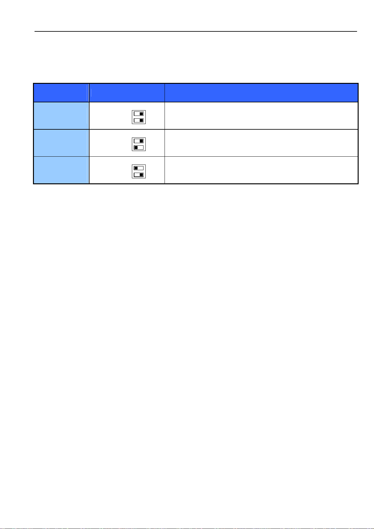
4.3 QUADpack compatible setting
Mx_I0
Mx_I1
2A_135
2A_246
MD_135
MD_246
Mx_I0
Mx_I1
2A_135
2A_246
MD_135
MD_246
Mx_I0
Mx_I1
2A_135
2A_246
MD_135
MD_246
ON OFF
ON OFF
ON OFF
Motor current: 0.5 A
Chopper
scheme:
Motor current: 1.0 A
Chopper
scheme:
Motor current: 1.5 A
Chopper
scheme:
"Slow decay"
To use "mixed decay" for all motors switch 'MD_135' and
'MD_246' off.
"Slow decay"
To use "mixed decay" for all motors switch 'MD_135' and
'MD_246' off.
"Slow decay"
To use "mixed decay" for all motors switch 'MD_135' and
'MD_246' off.
Page 9

SIXpack 2 – manual (V1.01 / May 5th, 2006) 9
5 Fundamental Functions – First Steps
This part of the documentation describes the use of SIXpack 2 via an example with limited functionality.
For additional functionality please refer to next chapter. In addition to the required steps in hardware set
up you should take into the operation the delivered Windows
5.1 Security Advise
To avoid damage to the SIXpack 2 please be aware that:
• Wrong connector pin assignment may destroy the SIXpack 2. Be extremely accurate at the
installation and when confectioning cables.
• Disconnecting the Motor while operational may destroy the SIXpack 2. Disable the motor current
by pulling the jumper, or better power down the device before connecting / disconnecting motors.
5.2 Basic Device Settings
5.2.1 SIXpack 2 Address
Before the SIXpack 2 is put into operation some adjustments of the device have to be checked,
eminently the address of the serial interface. It is set via the CANHI and CANLO switches and should be
set to zero by default. Refer to Figure 5.1.
RS232-Connector:
2: RXD
3: TXD
5: GND
7: RTS
8: CTS
CAN-Connector:
2: CANL
6: GND
7: CANH
CAN-TERM
6 7
21
12
8 9
54
3
9
8
A
7
6
5
4
3
F
2
0
1
CANLO CANHI
B
C
D
E
SIXpack 2
9 8 7 6
12345
9
8
A
7
B
6
C
5
D
4
E
3
F
2
0
1
123 12
34
12
TM
-Software.
6 5 4 3 2 1 2 11 2
READY:
1: GND
2: OUT
(open collector,
100mA, 35V)
RS485:
1: GND
2: RS485+
3: RS485 4: GND
5: RS485+
6: RS485-
POWER:
1: GND
2: Vcc(+15,40V, 7A)
CAN-Adress setting
Baudrate setting
1-2: JP2
3-4: JP1
RS232/RS485-
Selector
Seven-Segment
Display
RS485-Term.
100 OHM
Figure 5.1: Jumper and connectors
5.2.2 Option RS232/RS485
The SIXpack 2 shall be controlled with RS232 interface. The jumper RS232/RS485 has to be at RS232
(Refer Figure 5.1).
The use of RS485 is described in chapter 6.1.1.
Page 10

SIXpack 2 – manual (V1.01 / May 5th, 2006) 10
5.2.3 Baudrate of serial interface
The baud rate of the serial interface is set via jumper JP1 and JP2 (refer Figure 5.1).
JP1 JP2 Baud rate RS232/RS485 Baud rate CAN
X X 9600 1 Mbit/s (*)
- X 57600 500 kbit/s (*)
X - 38400 125 kbit/s (*)
- - 19200 250 kbit/s (default)(*)
Table 5.1: Adjustment of baudrate with jumpers
(*): The SIXpack 2 has an internal buffer for 16 CAN commands which need about 2ms execution time
each. This might limit the maximum data throughput.
The command GetInputValues (SQPack-Tab I/O, $30) provides the actual jumper configuration in the
variable AllInputs.
Bit 6 = Jumper1, Bit 7 = Jumper2
The baud rate for RS232/485 can be modified by software also. This setting is not stored permanently.
In order to get the actual jumper-configurations send CMD $30.
5.2.4 Termination of CAN/RS485
Each interface can be terminated by setting the jumpers “TERM CAN” and “TERM RS485” (refer Figure
5.1).
5.2.5 Seven-segment display
The seven segment display shows the number of active motors. With an appropriate power supply a “0”
is shown at start. The decimal point indicates that a reference search at any motor is accomplished.
If a malfunction occurs the display shows “8”, “C” or “F”. Try to restart the SIXpack 2.
5.2.6 Driver enable
The jumper “Driver enable” (close to the motor connectors) enables (jumper set) or disables (jumper
open) the drivers for all motors. If the drivers are disabled, i.e.. jumper open, it is safe to disconnect the
motors while power on and retain the actual settings of the SIXpack 2.
Hint: It is possible to use a switch to enable/disable the drivers.
Driver enable
Multifunctional
"RS232"
DIP-switches:
1: M2 I 1
2: M2 I 0
3: M1 I 1
4: M1 I 0
5: MD246
6: MD135
7: 2A_246
8: 2A_135
1
910
12
2
3
78
4
56
5
34
6
7
12
8
SIXpack 2
Motor connectors
Figure 5.2: Driver enable, DIP switches and motor connectors
1
2
3
4
5
6
7
8
DIP-switches:
1: M6 I 1
2: M6 I 0
3: M5 I 1
4: M5 I 0
5: M4 I 1
6: M4 I 0
7: M3 I 1
8: M3 I 0
Page 11

SIXpack 2 – manual (V1.01 / May 5th, 2006) 11
r
r
r
r
5.2.7 Adjusting the maximum current
The maximum current of the SIXpack 2 can be set via DIP-switches. The switches are close to the motor
connectors. The former QUADpack and SIXpack had different maximum currents. With the appropriate
DIP-switch configuration they are fully compatible.
Current DIP-switch position description
ON OFF
0.5 A
0.8 A
1.0 A
1.5 A
2.0 A
Mx_I0
Mx_I1
2A_135
2A_246
Mx_I0
Mx_I1
2A_135
2A_246
Mx_I0
Mx_I1
2A_135
2A_246
Mx_I0
Mx_I1
2A_135
2A_246
Mx_I0
Mx_I1
2A_135
2A_246
Mx_I0
Mx_I1
2A_135
2A_246
Mx_I0
Mx_I1
2A_135
2A_246
ON OFF
ON OFF
ON OFF
ON OFF
ON OFF
ON OFF
Current setting for each motor (index x specifies the moto
number)
Current setting for each motor (index x specifies the moto
number)
Current setting for each motor (index x specifies the moto
number)
Current setting for each motor (index x specifies the moto
number)
2.0 A maximum current for all motors
2.0 A maximum current for motor 1, 3 and 5.
Current setting for motor 2, 4 and 6 via 'Mx_I0' and 'Mx_I1'.
2.0 A maximum current for motor 2, 4 and 6.
Current setting for motor 1, 3 and 5 via 'Mx_I0' and 'Mx_I1'.
Table 5.2: Adjusting maximum current
Page 12
SIXpack 2 – manual (V1.01 / May 5th, 2006) 12
5.2.8 Adjusting chopper mode
The SIXpack 2 supports “Mixed Decay” which provides reduced motor resonance at medium velocities
and improved microstep exactness. This mode can be switched off by the DIP-switches if desired.
Chopper
Scheme
Mixed decay
(all motors)
DIP-switch position description
MD_135
MD_246
ON OFF
Mixed decay for all motors
Mixed decay
(motor 1, 3 and
5)
Mixed decay
(motor 2, 4 and
6)
MD_135
MD_246
MD_135
MD_246
ON OFF
Mixed decay for motor 1, 3 and 5
ON OFF
Mixed decay for motor 2, 4 and 6
Table 5.3: Adjusting chopper mode
5.3 Connections
Initial operation of the SIXpack 2 is possible after installing current supply and serial interface.
5.3.1 Current supply
Any power supply unit with an output voltage of 15-48V may be used. The required current is conform to
the usage and quantity of motors. The connector is labeled POWER. Be aware that the polarity is correct
and make sure that your supply voltage never exceeds the absolute maximum rating.
With an appropriate current supply the LEDs “+5V” and “+24V” light up and the 7-segment-display shows
zero. If the display shows “8”, “C” or “F”, or the unit resets continuously, an internal defect has been
detected. When continuous resets occur, the Flash memory could be erased. You can try to swap flash
with an other device.
5.3.2 Serial interface
The RS232 interface is connected via a null modem cable with one serial interface of the PC.
5.3.3 Motor connectors
CAUTION: Connecting or disconnecting while power on may damage the motor drivers
of the SIXpack 2.
The function “Driver enable” (refer to 5.2.6) provides the possibility to disconnect motors while the
modules power is on. Thereby all actual settings are retained.
The motors are connected with the 8 pin connectors. The pinning of the connectors are as follows:
Page 13

SIXpack 2 – manual (V1.01 / May 5th, 2006) 13
A_ln(analog input 0...5V)
Refln (reference input, 10k
intern pullup resistor, 5V level,
2.5V threshold with hysteresis)
Vcc (5V, 15mA, 33 Ohm)
Ground (for A_ln, Refln)
Phase B, Connector 2
Phase B, Connector 1
Phase A, Connector 2
SIXpack 2
Phase A, Connector 1
Figure 5.3: Pinning of motor connector
For fundamental functions the pin connections for the motor phases are important. Connect the motor
coils indicated in Figure 5.4 with the connector of the pack.
PHB2
M
PHB1
PHA2
PHA1
SIXpack 2
Figure 5.4: Connecting motor coils
5.3.4 Connector specifications
Motor connector: Producer: AMP Connectors (www.amp.com)
Item number: 0-0770602-8 (case)
0-0770666-1 (crimp contacts)
0-0058517-1 (crimping tool)
Power supply/RS485: Producer: Weidmüller (www.weidmueller.com)
Item number: 1716320000 (2-pole, VDC, Ready)
1716360000 (6-pole, RS485)
Page 14
SIXpack 2 – manual (V1.01 / May 5th, 2006) 14
5.4 Start-up with software SQPack
After adjusting the necessary hardware of the SIXpack 2 the first function tests with the WindowsTM
program SQPack can be done.
5.4.1 Installation
The installation of the program SQPack is accomplished by copying the file “SQPack.exe” to any location
on your PCs hard disc. At first start the file “SQPack.ini” is created to save actual settings. To reset the
settings of the software simply remove this file.
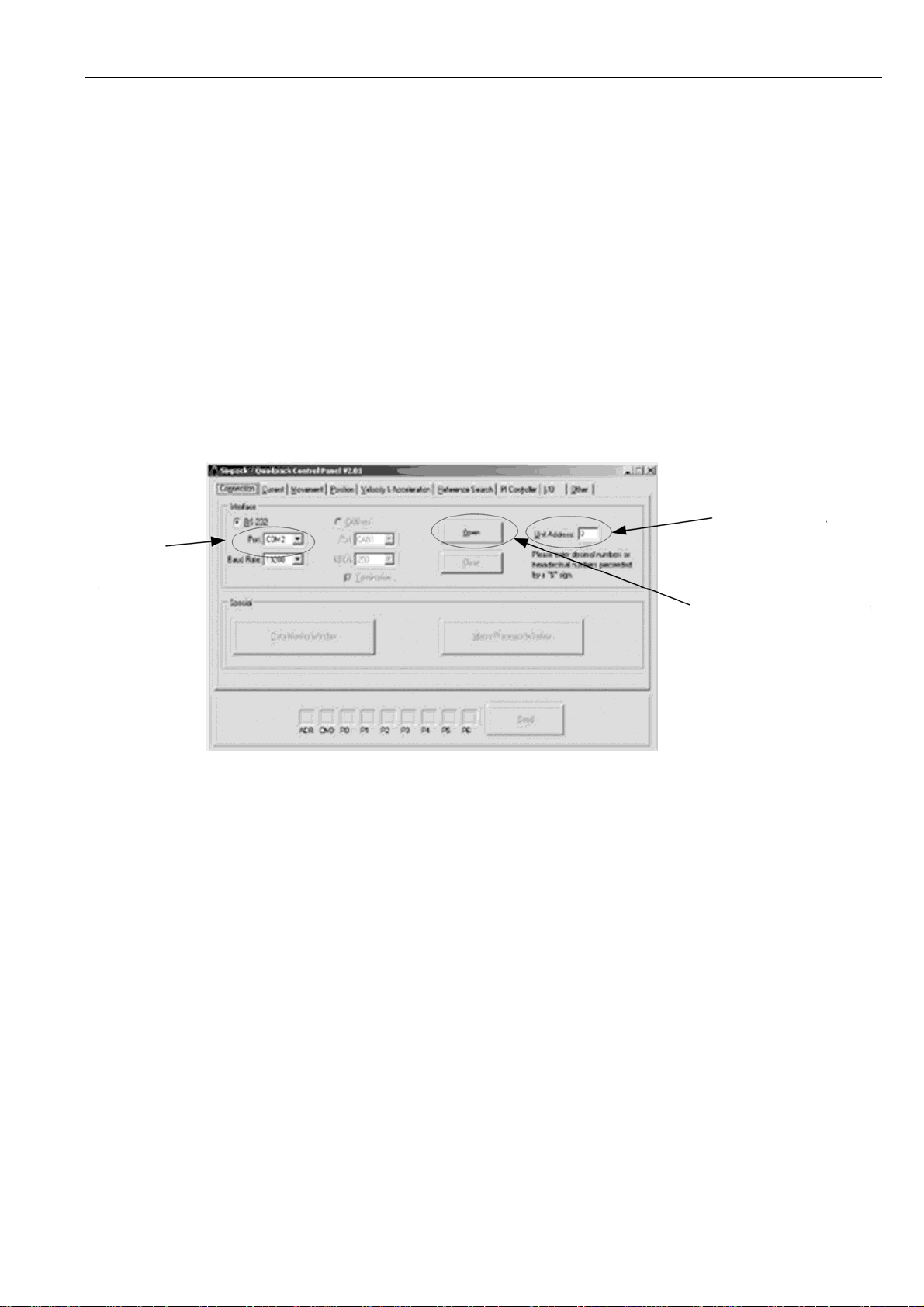
5.4.2 Initiation
To initiate the program double click “SQPack.exe”. A window with nine tabs is opened. In front is the tab
“Connection”. To establish a connection to the SIXpack 2 choose the correct COM-Port. The other
settings should be at necessary values.
2. step:
1. step:
choose
COM port
SIXpack II adress
(see Hex switches)
3. step:
establish connection
Figure 5.5: Setup of SQPack
5.4.3 Functional test: Get system information of SIXpack 2
To check the connection the command GetUnitInformation is useful. Choose the tab “Others” and
activate in box “Commands” the line “$43: Get Unit Information”. If the connection settings are done
correctly it is possible to click the button “Send” at the bottom of the window to transfer the command to
the SIXpack 2. If a connection is established the values for “Firmware Revision”, “Reset Flag”,
“Temperature” and “S/N” are displayed in the box “Parameters”.
5.4.4 “First steps”: Movement of motor
The significant advantage of stepper motors is to turn to a specific position. The motor is accelerated by
the SIXpack 2 to an assigned velocity and decelerated in time to reach the specified position.
Therefore choose on the tab “Movement” the command “Ramp”. The variable “Position” represents the
exact target position. By clicking the “Send” button the motor turns to the specified position.
5.4.5 Concept of SIXpack 2 interface protocol
The SIXpack 2 is controlled by frames of 9 byte generally. The software SQPack displays this frames in
the lower part of the window next to the “Send” button. The nine bytes are shown hexadecimal.
At start it is easiest to create the frames by software and add these eventually to an own program.
Page 15
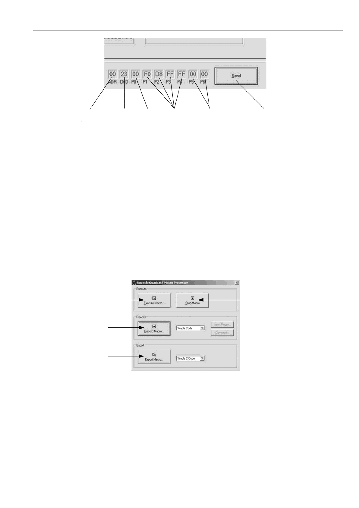
SIXpack 2 – manual (V1.01 / May 5th, 2006) 15
SIXpack II
adress
Command
$23
motor
number
variable
position
not assigned for
this command
Button to send
datagrams
Figure 5.6: Command frames of “SQPack”
5.4.6 Macro functions of SQPack
At the tab “Connection” the software provides the function “Macro Processor Window” to store command
sequences to a file. This file can be opened by an ASCII-Editor and the command sequence is formatted
as follows:
SendToPack ( adr, cmd, p0, p1, p2, p3, p4, p5, p6 )
“SendToPack” stands for the function which sends nine bytes to the SIXpack 2 via the serial interface.
The parameters are hexadecimal.
A Macro is generated by clicking the button “Record Macro” on the tab “Macro Processing Window“. A
dialog box is opened to name the file in which the macro is saved. Afterwards any commands can be
saved to the file until the recording is ended by clicking “EndRecording”.
CAUTION: Some commands are excepted at stopped motor only. According to this refer to the
command description.
open and
execute
stored macro
record
macro
export
macro as
source code
stop macro
execution
Figure 5.7: Macro function of SQPack
5.5 Operation with reference/ending points
Most applications with stepper motors need a reference point to acquire the actual position of the motor.
The reference point of each axis is detected by the SIXpack 2 with a reference search. The positions
scaling determined by type of the application. It is a linear axis if the motor moves a mechanic with
defined end and start point. Every point on the axis is assigned to a position between start and end point.
If there is no end or start point it is a rotating axis. The position values for the axis are defined for one
rotation. The value starts at zero again after full revolution.
Page 16

SIXpack 2 – manual (V1.01 / May 5th, 2006) 16
5.5.1 Types of reference point definitions
The SIXpack 2 provides two completely different types to define the reference point:
• Mechanical stopper for reference point (linear axis only)
At start point or end point a stopper for the mechanic of the axis is build in. At reference search
the SIXpack 2 moves the respective axis in direction of the stopper (defined by the flag
MT_NULLLEFT, SQPack-tab: “Reference search”, CMD $15) for a distance of Poslimit * 5/4.
The multiplication with 5/4 causes the SIXpack 2 to reach the stopper before end of the reference
search. The motor is mechanically stopped, reference point is reached.
• Electrical reference point
At any point of the positioning scale of the axis an electrical switch is implemented which is
activated by the passing motor. The SIXpack 2 catches this for reference point.
A reference switch attached one end of a linear axis can be used as end switch. At activation of
the switch the motor stops.
5.5.2 Hardware installation
5.5.2.1 Connection of electrical reference switch
The reference switch is connected to the pins „Ref_In“ and „GND“. Optionally a series resistance of
about 2.2kOhms can be inserted to match EMC demands. In general using an opener, i.e. a normally
closed switch is advisable. So broken cables can be detected. The reference input is equipped with a
Schmitt-trigger.
Ref_in
opener switch
2k2 Resistor
(optional)
GND
SIXpack 2
Figure 5.8: Connecting reference switch
5.5.2.2 Wiring with stop-switches
To prevent driving beyond the ends of a linear axis stop-switches can be used. They are connected to
pin „A_In“ of the motor connector. Again, openers should be used as stop-switches for the reason
mentioned above.
Page 17

SIXpack 2 – manual (V1.01 / May 5th, 2006) 17
A_ln
Stop_L Stop_R
SIXpack 2
2k2
optional
5V
GND
2k2
optional
Figure 5.9: Connecting two end switches
5.5.2.3 Wiring with combined Stop-/Reference Switch when using Openers
Mounting the reference switch at one of the ends of the axis it can be concurrently used as stop-switch
thus saving the respective stop-switch.
A_ln
optional
2k2
Stop_R
optional
2k2
Ref. switch
optional
2k2
5V
SIXpack 2
GND
Figure 5.10: Combination of reference and end switches
: In this circuit the reference switch is concurrently used as left stop switch if flag StopNull is set.
Note
The flag NullPositive has to be set, to match the opener. Reference search is done in left direction (flag
NullLeft set).. Refer to CMD $15.
5.5.3 Reference search software configuration
Most settings for the reference search are adjusted with the command SetMotorParameters (CMD $15,
SQPack-tab: “Reference search”).
5.5.3.1 Calculation of value range
The positioning is defined by the motors count of micro steps. The pack has 16 micro steps per full step
which angular is defined by the motor standards. Please check the motors datasheet for details.
Calculation of the value range of a linear axis is easiest experimental. Therefore set the axis mechanics
manually to the start position and move it with use of SQPack to the end of the axis. Use the command
“Ramp” (CMD $23, SQPack-tab: “Movement”) and set value of Position higher until the end of the axis is
reached. Position represents now the length of the axis.
Page 18

SIXpack 2 – manual (V1.01 / May 5th, 2006) 18
5.5.3.2 Linear Axis, mechanical reference point
Important parameters for configurations are:
• variable Poslimit,
• Flag MT_NULLLEFT,
• Flag MT_MECHREF.
The value range of the axis is specified in Poslimit. The SIXpack 2 evaluates with this value the length
of the reference search (5/4 * Poslimit). MT_NULLLEFT defines the direction of the reference stopper.
It is on the left side of the axis for NullLeft = 1.
For Poslimit = 10000 the produced dataset by SQPack is:
SendToPack($00, $15, $00, $10, $27, $00, $00, $10, $04).
The reference search is started with command StartReferenceSearch (CMD $23), from the SQPack-tab
“Reference Search”. The dataset is as follows:
SendToPack($00, $22, $00, $00, $00, $00, $00, $00, $00).
5.5.3.3 Linear Axis, reference switch at beginning of axis
The hardware configuration described above is the starting point. For the basic configuration only the
variables Poslimit, MT_NULLLEFT and MT_NULLPOSITIVE are relevant. MT_NULLLEFT and
MT_NULLPOSITIVE are set to 1. The resulting dataset evaluated by SQPack for an axis of the length of
Poslimit = 33333 is:
SendToPack($00, $15, $00, $20, $A1, $07, $00, $10, $40).
Start of reference search as described in 5.5.3.3.
5.5.3.4 Linear axis, combined end/reference switch left, end switch right
Starting point is the same. Additionally to Poslimit, the Flags MT_NULLLEFT and MT_STOPNULL
have to be set. The resulting dataset for Poslimit = 500000 is:
SendToPack($00, $15, $00, $20, $A1, $07, $00, $50, $40).
Start of reference search as described in 5.5.3.3.
5.6 Basic configurations for operation
5.6.1 Adjusting motor current
Additionally to the possibility to adjust the maximum motor current manually by the DIP switches (refer to
5.2.7) there are different ways to adjust the motor current to the demands of the system with the
software.
The maximum current for the motors has to be determined. You can find it in the motors datasheet.
Commonly the producer provides the current for a full step. This means for the SIXpack 2 that a current
of 1.4 times the peak current is possible. The command PeakCurrent (CMD $10, SQPack-tab „Current“)
configures the maximum current.
CAUTION: The maximum current is always compound for two motors. The current counts for motor n
and also for motor n+1 !!!
Additionally to the motor number a value, functioning as divider for the maximum current of the
SIXpack 2 is transmitted. Value range is 0…255.
Page 19

SIXpack 2 – manual (V1.01 / May 5th, 2006) 19
divider = (maximum current*256) / (2000mA * DIP switches)
5.6.2 Configuration of acceleration and velocity
The exact and calculation and configuration of micro steps and the description of parameters concerning
calculation of micro steps follow in “6 Full Functionality”. In this chapter the detection and configuration of
maximum acceleration and velocity is described, only.
5.6.2.1 Configuration of initial velocity
CAUTION: This value may be changed at motor standstill, only !!!
The initial velocity characterizes velocity at start of motion ramp. Value range is 1…256. The command
StartVelocity (CMD $13, SQPack-Tab „Velocity & Acceleration“) configures the initial velocity in the
variable VStart.
Attention: This command changes the two other values VMin and ClkDiv, also. These functions are
explained in the Instruction Set. The default values VMin = 5 and Div = 2 are sufficient here.
Example dataset: VStart = 100, VMin = 5, Div = 2 for Motor 3:
SendToPack($00, $13, $02, $0A, $00, $0A, $00, $02, $00)
5.6.2.2 Acceleration and maximum velocity
Acceleration and maximum velocity are related closely. Starting from VStart a velocity with fixed
frequency is raised by AMax until VMax is reached. A detailed instruction is provided in the Instruction
Set.
Both values are set with command SetAMaxVMax (CMD $14, SQPack-Tab „Velocity & Acceleration“).
AMax has to be ranged from 1 to (VStart*64), VMax from 1 to 511.
Example dataset: AMax = 200, VMax = 400 for Motor 4:
SendToPack($00, $14, $03, $C8, $00, $90, $01, $00, $00).
5.6.3 Motion control
Divers commands for the movement of the axis are combined in chapter 6.6 “Commands for axis
movements”.
Page 20

SIXpack 2 – manual (V1.01 / May 5th, 2006) 20
6 Full Functionality
6.1 Inputs and Outputs
6.1.1 RS232 or RS485 interface
The RS 485 interface is a bi-directional 2-wire interface and can handle up to 255 slave devices in halfduplex mode. The RS 232 interface can be used accordingly, however it is not possible to connect
multiple transmitters to the receiver input. The baud-rate is pre-configured to 19200 baud. It can be
changed via command.
Instructions consist of a 9 byte word, which in turn consist of the address of the unit, a command byte
and if required parameters with a length of up to 7 bytes.
Address command P0 P1 P2 P3 P4 P5 P6
The command word always has to be completely transmitted during a parameterized timeout
(s. CMD $41). It will be aborted and not interpreted, when a break-code is received. If errors occur the
interface can be newly synchronized via break-code.
The address of the unit can be set via rotary switches (scanned on reset).
During parameter read out an instruction will be transmitted only after an adjustable transmitter switchover time (s. CMD $40; pre-set to 6ms) has passed. This allows the transmitter to switch to receiving
mode. Ditto for the opposite direction: The PACK continues to drive the line for a pre-set time after
transmitting a message. The direction can be checked at the RTS-line of the RS 232-interface (negative
= SIXpack 2 is in sending mode). The CTS-line will be ignored.
When a valid command word is received, the status LED flashes.
6.1.2 CAN interface
The integrated CAN-Controller supports the full-CAN-specifications 2.0A with 11 address bits. Telegrams
with a fixed length of 8 bytes are used. The address of the unit (upper 8 address bits) can be set via
rotary switches (scanned on reset). The lower 3 address bits are fixed to “000“. Take care: According to
the CAN standard 0 is no valid address! Address range: $008 to $7F8 (in increments of 8).
After receiving the first valid instruction via CAN, control via RS 232 or RS 485 will be terminated. The
CAN response address is transferred to SIXpack 2 in a 8 bit format, like at RS 232 / 485. For responding
the address is shifted to the left by 3 bits, resulting in the same address range as defined above. If
continuous error conditions occur, CAN and RS 232 / 485 will be newly initialized.
For a table to configure the Baudrate refer to 5.2.3.
6.1.3 Ready output
The Ready output can be activated (low, open collector, with pullup to 4.3V internally), whenever a motor
is active (velocity above 0) or at reference search. The ready output will be switched within 2ms after
start/end of motor action. The repeatability (Jitter) matches approximately the micro step rate at start or
stop (see command SetVMinVStart, CMD $13, SQPack-Tab „Velocity & Acceleration”).
6.1.4 Multifunctional connector “RS232”
The 10 pin connector “RS232” next to the motor connectors offers divers inputs and outputs for
additional functions of the SIXpack 2.
Page 21

SIXpack 2 – manual (V1.01 / May 5th, 2006) 21
SIXpack 2
1 2
3 4
5 6
7 8
9 10
1: RXD
2: TXD
3: CTS
4: RTS
5: GND
6: GND
7: Analog In (0..5V)
8:TTLOUT1(270 Ohm)
9:TTLIO1 (270 Ohm)
10: 5V (120mA)
Figure 6.1: Pinning of multifunctional connector “RS232”
Pin Use Description
1, 2, 3, 4
connected directly to the
sub-D-connector of the
RS232 interface
electrically identical with the interface at the sub-D connector and
can not operate independent
5, 6 ground
7 analog input (0..5V) value readout with command GetInputValues (CMD $30)
TTL levels, internal resistor 270Ω. Value readout with command
8 digital output (TTL)
SetOutputs (CMD $32) in variable TTLOUT1. Function “Ready
output” is activated if TTLOUT1_READY is set.
TTl levels, internal resistor 270Ω. Command SetOutputs
(CMD $32) :
9 digital I/O port (TTL)
TTLIO_INPUT = 0: Output, set with variable TTLIO1
TTLIO_INPUT = 1: Input, value readout with variable TTLIO1 of
GetInputValues (CMD $30).
10 output, max 5V, 120 mA
Table 6.1: Pin description of multifunctional connector “RS232”
6.1.5 RS 232-Remote Control via CAN-Interface
The RS 232-interface can be controlled via CAN. Therefore the baud-rate is set via command “RS 232change baud-rate“. Only 8 bit, 1 stop bit and no parity is possible. Of course 7 bit and parity could be
simulated by the user. The response address for bytes received via RS 232 and the packet size for
transferring received bytes are configured by a separate instruction.
To forward bytes received via CAN to RS 232, the CAN-address of the PACK is incremented by 1, i.e.
the lower 3 bits are “001“. Every byte which is received with this address will be transferred to the
RS 232-interface. 1 to 8 bytes can be transferred at once. Please note that the RS 232-interface needs
sufficient time before the next block is transmitted. To be sure that the RS 232-cache is empty, it can be
checked via command. There is no CTS-handshake, however the CTS-line can be read-out
(s. CMD $44).
Bytes received via RS 232 will be sent to the pre-set response address, as soon as the pre-set number
of bytes has been received. Incorrect messages will be ignored now. If the configurable RS 232-timeout
has expired, remaining bytes will be sent (→ see CMD $41).
Page 22

SIXpack 2 – manual (V1.01 / May 5th, 2006) 22
6.2 Programming
The concept programming the SIXpack 2 is based on dataset of a fixed length. To allow networks the
datasets have to contain the SIXpack 2 address.
The commands dataset itself contains a command byte and seven bytes to transfer parameters. The
bytes have to be transmitted even if they contain no data.
Figure 6.2: Command dataset
6.2.1 Hints for Programming
6.2.1.1 Strategy for Parameter Setting
The Pack can be parameterized for standard applications with a few commands since it is pre-set with
default values. However these default values should not substitute a thorough configuration of all
parameters in a given application. Normally the following parameters should be configured for your
application:
6.2.1.2 Setting of Motor Current
Configure maximum current (s. CMD $10) and current control (s. CMD $11) as needed. The minimum
current (which provides proper microstepping) selected by current control is 19% (Index 6) for every
parameter.
6.2.1.3 Velocity Configuration (global)
Calculate clkdiv (s. CMD $12, SQPack-Tab “Velocity & Acceleration”) with the step frequency formula (s.
begin of chapter Instruction Set) so that the required maximum step velocity is achieved with v
and small values div
= 0 or 1.
i
= 511
i
6.2.1.4 Setting of starting Velocity, max. Velocity and max. Acceleration
These values (s. CMD $13 and $14) should be adapted to the motor type, mechanical load, and so on.
As a reference value div
should be set so, that the maximum velocity vmax could be set between 256
i
and 511. This way maximum resolution is obtainable. Then the acceleration amax can be configured.
The velocity vstart should not be set too low.
6.2.1.5 Setting of Motor Parameters and Reference Search Parameters
These settings describe the axis type, the reference search, and so on. For time saving purposes both,
fast reference search FastRef (s. CMD $15 P6, Bit1) should be activated and the maximum velocity for
this reference search should be set. To avoid errors caused by vibrations of the motor during fast
reference search, de-bouncing of the reference switch FilterSwitch (s. CMD $15 P5, Bit7) should be
activated, too, and the mask for reference point de-bouncing (s. CMD $16) should be programmed with
an applicable value. vmin (always used with predivider div
the reference switch. The fastest possible vmin will be choosen automatically when its value is set to 0.
set to 3) will be used while exactly locating
i
Page 23

SIXpack 2 – manual (V1.01 / May 5th, 2006) 23
Stop
Left
null position
testnullrange
Reference
null point-offset
reference point
motor
traveller
poslimit
positive
direction
StopR
Stop
Right
Graphic assumes null-left Flag is set and null point offset is positive(s.
In this configuration the reference switch is reliably closed at position null.
Note: testnullrange >= width of reference switch!
settings: null point-offset, poslimit -> CMD $15
testnullrange -> CMD $18
CMD $15
).
• The reference switch defines the zero position. The zero position can be moved further into the
switch using the nulloffset setting. If testnullbit is set it must be active at the end of T0 and the
delay time of the filter.
• Activation of the switch is only allowed in the testnullrange to testnull around the zero position. If
you reference to the edge of the switch and never exceed the zero position the testnull range can
be choosen around 1-2 fullsteps * 16. In all other cases you must choose it at least slightly larger
than the active area of the reference switch or half of this for nullcenter motors.
• The reference search requires proper poslimit (0..0x7FFFFFFF) settings! For cyclic axis you must
set poslimit to the number of microsteps per revolution, for linear axis it should cover at least your
whole intended driving range to avoid unintended or interrupted reference drives.
6.2.1.6 Problems with fast Search for Reference
The fast search for reference will function properly only if CMD $15 and $16 are set correctly, especially
those for the reference switch. Also is it sensitive to noise pulses in the wiring of the reference switch –
should the fast reference search stop abruptly, anti-noise measures have to be taken for the reference
switch input.
6.2.1.7 Interlacing of Requests
Requests must not be interlaced. Each request should wait for the response of the SIXpack 2 before
transmitting a new command. However a delayed response with RS 232 may be outstanding in parallel.
6.2.1.8 Default Values
For testing purposes here is a list of default values for motor parameters:
clkdiv=5; div=2; // 26 kHz microstep-frequency
vstart=5; // starting with 254 Hz (should be >=8)
amax=128; vmax=511; // increments v by 128/16=8 each 2 ms
vmin=4; vrefmax=100; // 102 Hz / 5086 Hz for reference drive
poslimit=400*16; // 400 full- = 6400 microsteps/revolution
testnullrange=15*16; // ignore switch in range –240 ... 240
Peak current=128; // define 100% curr. control as 400 mA
T0=500; // wait 1000 ms before standby
I0=00%(!); // waste no energy for unused motors
I1=50%; // power stopped motors with 200 mA
I2=75%; // power v const. motors with 300 mA
Page 24

SIXpack 2 – manual (V1.01 / May 5th, 2006) 24
I3=100%; // power accelerat. motors with 400 mA
motortype= Delayedtest0 | NullCenter | Filterswitch | FastRef;
De-bounce mask=$0FFF; // Filter delay 12-1 cycles = 22 ms
Readymask=$3F; // check any active motor
Refer.-Readymask=$3F; // check any referencing motor
propdiv=8; // v = position-difference / 8
intdiv=129; // v += pos-difference integral / 129
intclip=129; // clip pos-difference integrals > 129
intinpclip=1; // integrate pos-difference of max. 1
All other values are set to 0, i.e. the functions are disabled.
6.2.2 Examples
Attention:
command and waits for the missing bytes.
$ indicates that the value is in hexadecimal notation!
All 9 Bytes must be sent to the interface, otherwise the SIXpack 2 does not recognize the
6.2.2.1 Setting motor parameters
CMD $15 contains information about the motor and settings for the reference drive.
For more details see Hints for Programming and CMD $15 in the Instruction set!
Bit 7
P
0
0
0
0
0
MotorNr.1
Pseudocode:
SendToPack(address); // Address of the Pack(Sixpack2)
SendToPack($15); // Command in hexadecimal notation
SendToPack(P0); // Motor number (0...5)
SendToPack(P1); // poslimit LSB
SendToPack(P2);
SendToPack(P3);
SendToPack(P4); // poslimit MSB
SendToPack(P5); // further settings, for more information read the instruction set
SendToPack(P6);
=
0
0
0
(0...5)
Bit 0
0
0
1
0
0
LSB
( = 90 hex
= 144 dez)
0
0
0
0
1
,
,
3
P
P
P
1
,
P
2
0
0
0
3rdSB 2rdSB
( = 1 hex
= 1 dez )
4
1
0
0
0
0
(
=
0
0
4
0
0
0
0
)
!
s
t
r
i
f
L
B
S
0
0
0
0
-> poslimit = 00000190 hex ( = 400 decimal)
NOTE: P5, Bit1=0 -> linear motor -> poslimit=whole intended driving range
0
0
2
=
P
5
MSB
0
1
1
StopNull
FilterSwitch
0
1
0
TestNull
0
0
+ 64
+128
0
0
0
0
0
0
0
0
200
( = C8 hex )
P6 = 90
0 1 0 1 1 0 1 0
8
DelayTestNull
StopSoft
NullPositive
FastRef
+ 8
+16
+64
90
( = 5A hex )
2
Page 25

SIXpack 2 – manual (V1.01 / May 5th, 2006) 25
6.2.2.2 Navigating the motor
CMD $23 prompts the concerned motor to drive to the position, which stands in P1 ... P4.
Pseudocode:
sendToPack(address); // Address of the SIXpack2
sendToPack($23); // Command for starting a trapezoidal Ramp
sendToPack(motno); // Number of the concerned motor (0...5)
sendToPack(destinationLSB); // Least significant Byte of the target position
sendToPack(destination3rdSB);
sendToPack(destination2ndSB);
sendToPack(destinationMSB); // Most significant Byte
sendToPack(0); // fill 9 bytes
sendToPack(0); // fill 9 bytes
6.2.2.3 Inquiring the actual position of a motor
CMD $20 returns the 4-byte value with the actual position and status of the concerned motor. In addition
P6 specifies whether a stop-switch was active. This is e.g. when the motor has lost steps and if during
driving back to the real null-point the switch is found too early.
Pseudocode:
sendToPack(address); // Address of the SIXpack
sendToPack($20); // Command for inquiring actual position and action of one motor
sendToPack(motno); // Number of the concerned motor (0...5)
sendToPack(receiver); // address of the receiver
sendToPack(0); // fill 9 bytes
sendToPack(0); // fill 9 bytes
sendToPack(0); // fill 9 bytes
sendToPack(0); // fill 9 bytes
sendToPack(0); // fill 9 bytes
cmd = receiveFromPack(); // should be $20
motno = receiveFromPack(); // should be the same number as the sent
posakt_byte1 = receiveFromPack(); // LSB of the actual Position
posakt_byte2 = receiveFromPack();
posakt_byte3 = receiveFromPack();
posakt_byte4 = receiveFromPack(); // MSB of the actual Position
act_action = receiveFromPack(); // Information about the actual action of the motor
stop = receiveFromPack(); // is 1 when null-switch is active
Page 26

SIXpack 2 – manual (V1.01 / May 5th, 2006) 26
6.2.2.4 Starting a two axis interpolated movement
Linear motions with multiple axes can be driven. For this, the destinations have to be set via CMD $26
and then the trapezoidal Ramp can be started via CMD $50. In the example the axis 1 is navigated to
position 10000 and in parallel the axis 2 to position 2000.
Pseudocode:
sendToPack(address); // Address of the Sixpack2
sendToPack(0$26); // Command for setting the destination
sendToPack(0); // Motor 1
sendToPack($E8); // 232
sendToPack($03); // 3*256=768
sendToPack($00);
sendToPack($00);
sendToPack(0); // fill 9 bytes
sendToPack(0); // fill 9 bytes
sendToPack(address); // Address of the Sixpack2
sendToPack($26); // Command for setting the destination
sendToPack(1); // Motor 2
sendToPack($D0); // 208
sendToPack($07); // 7*256=1792
sendToPack($00);
sendToPack($00);
sendToPack(0); // fill 9 bytes
sendToPack(0); // fill 9 bytes
sendToPack(address); // Address of the SIXpack2
sendToPack($50); // Command for multi-axis Interpolation
sendToPack($03); // 0000 0011=3, e.g. Mask for motor 1 and 2
sendToPack(0); // fill 9 bytes
sendToPack(0); // fill 9 bytes
sendToPack(0); // fill 9 bytes
sendToPack(0); // fill 9 bytes
sendToPack(0); // fill 9 bytes
sendToPack(0); // fill 9 bytes
Page 27

SIXpack 2 – manual (V1.01 / May 5th, 2006) 27
6.3 Adjusting SIXpack 2 to motors micro step characteristics
6.3.1 Calculation of micro step frequency
The SIXpack 2 operates with a fixed micro step frequency of 16 micro steps every full step. The
programming positions are specified in micro steps in relation to zero. Following formula calculates the
given motors micro steps for a whole rotation:
Number of micro steps / rotation = 360° / Full step angle * 16
The full step angle is specified in the motors datasheet.
The absolute micro step frequency, the number of steps per second, in relation of the motors actual
velocity settings is described with following formula:
f
f
stepmicro
−
=
clkdiv
clk
v
⋅
i
+
1
• Full step frequency = 1/16micro step frequency
• f
is 20MHz
clk
• Clkdiv (ClockDivider, $12, SQPack-Tab “Velocity & Acceleration”) is the same for all motors
(value range 0…31)
respectively vakt is the velocity of each motor (range: –511..+511)
• v
i
• div
(Div, SQPack-Tab “Velocity & Acceleration”) can be parameterized for each motor (range
i
0…3)
Note: The micro step frequency must not exceed 200 kHz.
div
+
14
2
i
6.3.1.1 Example
The starting position (get with GetPositionAndActivity, CMD $20, set with SetActualPosition, CMD $27)
is zero, target position is 116666 (refer to command StartRamp, CMD $23).
Actual full step frequency (f
) is calculated with given formula for f
full-step
micro-step
by multiplication with 16.
VAkt for accelerations is:
AMax/64
+VStart VAkt =
ms 2 t /
This formula is not valid for decelerations. To realize the actual function the SIXpack 2 decelerates more
slowly than it accelerates.
Parameter:
ClockDivider = 5,
Div = 2,
VStart = 16,
VMax = 128,
AMax = 5
Page 28

SIXpack 2 – manual (V1.01 / May 5th, 2006) 28
π
π
π
π
ϕ
π
π
6.3.2 Adapting the microstep-table to the motor characteristics
)(ϕf
2
1
1
2
0
0
2
up to 16 micro steps
1 full step
3
4
alternative motor characteristics (s. CMD $17)
A
(1)
0
( 16 val ues for gener ati ng t he curr ent)
0
(2)
(3)
(default) sinus (2)
triangle(3)
)(ϕf
2
y
1
6
micro s
t
eps within a
1 f
u
ll st
q
e
uadrant
c
b
m
o
h
2
r
box
p
ir
cle
x
Most motors have varying microstep lengths, due
to this the motor would drive discontinuously for a
sin -/ cos -current. In order to reach a smoother
step full / rectangle (1)
run, you can drive the motor with an adjusted
current, so that the motor’s characteristics can be
compensated. This current curves are generated
with the 16 values in the table set via CMD $17,
which describe a quarter period.
(s. left)
6.4 Reference point adjustments
Additionally to the standard configurations for end and reference switches described in chapter 5.5 there
are many possibilities to adept these settings to an individual configuration.
6.4.1 Coordinate plane of an axis
In standard configuration the position counter for each axis is zero. The target position value for a
movement is the absolute number of micro steps from zero to target position. The maximum value of
micro steps per axis is adjusted by variable Poslimit in command SetMotorParameters (CMD $15,
SQPack-Tab “Reference search”.
6.4.2 Reference point / reference switch
The reference point is defined by a mechanic stopper or a reference switch. If an active reference switch
is used, in opposition to the recommended passive switch (refer to chapter 5.5.2), the Flag
MT_NULLPOSITIVE (command SetMotorParameters, CMD $15) has to be set to zero
(MT_NULLPOSITIVE = 0).
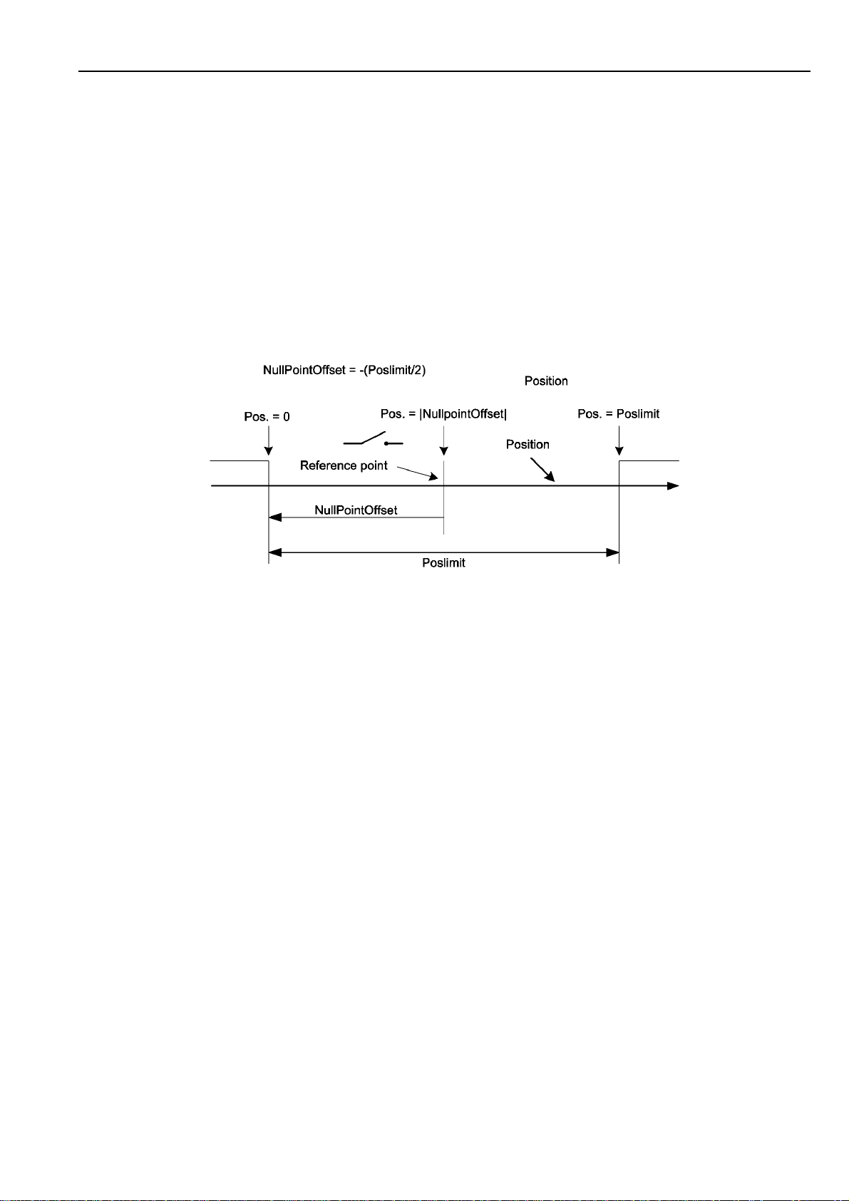
6.4.3 Moving zero-point
In basic configuration the reference point is the zero-point, also. With the command SetNullPointOffset
(CMD $18)an offset of the zero-point is possible. This can be important if for example the reference
switch is at the center of the axis but the programming allows positive values, only.
Page 29
SIXpack 2 – manual (V1.01 / May 5th, 2006) 29
6.4.4 Automatic reference search
The SIXpack 2 provides the possibility to start an automatic reference search at identified lost of steps.
To activate this function set the Flag MT_TESTNULL (command SetMotorParameters, CMD $15). The
intern position counter will be compared with the status of the reference switch. If the reference switch
reacts at wrong position or does not react at internally logic position, a reference search is started and
the flag STOPFLAG (command GetPositionAndActivity, CMD $20) set.
6.4.5 Adjusting activity zone of reference switch
Mechanical inaccuracy may lead to reaction of the reference switch a few steps too early or too late. If
an automatic reference search (MT_TESTNULL) is used this may start unintended reference searches.
It is possible to define a zone around the zero-point in which the status of the reference switch is not
checked using the commands SetNullPointOffset, (CMD $18) variable TestNullRange.
Figure 6.3: Coordinate transformation using „NullPointOffset“
6.4.6 Compensation of reference switch delay
At use of mechanic reference switches the problem of a delay time problem between mechanic and
electronic status change occurs often. To avoid dysfunction it is possible to delay the request of the
reference switch signal with PowerDownDelay. It is set and used in SetCurrentControl, CMD $11.
MT_DELAYTESTNULL is set and PowerDownDelay is 500 in basic configuration.
NOTE: PowerDownDelay is used for “power down”- delay (command SetCurrentControl, CMD $11),
also.
6.4.7 Elimination of glitches
In standard configuration the input signal at Refln is debounced for 22 ms. The change of levels has to
be constant in this time to be interpreted. This value is set with variable DebouncingTime (command
SetRefSearchParameters, CMD $16).
6.4.8 Adjusting reference search velocity
Fast reference search is activated in standard configuration (Flag MT_FASTREF of command
SetMotorParameters, CMD $15). At this configuration the axis is moved at reference search with the
velocity set in variable VRefMax (default VrefMax=100).
CAUTION: If MT_FASTREF is used the length of the axis has to be defined in the variable Poslimit.
Otherwise no correct reference search is possible. If MT_FASTREF is not set Poslimit is not
imperative. The reference search will be with a fixed velocity of 1.
6.4.9 Aborting reference search
A reference search is aborted with CMD $2B, SQPack-Tab “Reference search”.
Page 30

SIXpack 2 – manual (V1.01 / May 5th, 2006) 30
6.5 End switch configurations
To recognize a lost of steps and to avoid a possible mechanic damage it is reasonable to limit linear axis
as described in 5.5.
6.5.1 A_ln as end switch input
End switches to limit the axis can be connected to the input A_ln. Additionally to the in 5.5 described
setup with two opening end switches other configurations are possible:
A_ln is an analog input. In use as end switch voltage levels below a defined level are interpreted as the
left and above an other level as right end switch. These levels are defined with the command
SetStopSwitchLimits, CMD $30, SQPack-tab “I/O” in the variables MinLeft bzw. MaxRight.
6.5.2 Combination of end and reference switches
If the reference switch is at the end of the axis it can be used as en switch also. This function is activated
by setting the flag MT_STOPNULL (command SetMotorParameters, CMD $15). The flag
MT_NULLLEFT (command SetMotorParameters) defines, on which side of the axis the combined
end/reference switch is located.
MT_NULLLEFT = 0 Æ end/reference switch is on the right.
6.5.3 “Security Margin” for combined end/reference switch
As described in chapter 6.4.5 errors can occur if a switch reacts too late or too early. It is recommended
to provide the combined end/reference switch with a “security margin”.
The value set with the command SetMargin, CMD $1A, SQPack-tab “Reference search”, defines the
number of steps the SIXpack 2 runs into the reference switch (see Figure 6.3 also).
Figure 6.4: Adjustments for reference switch function
Page 31

SIXpack 2 – manual (V1.01 / May 5th, 2006) 31
6.6 Commands for axis movements
The SIXpack 2 provides different possibilities to move the axis. Which one to choose is related to the
demands of the application.
Basically there is the possibility to move the motor on the axis from a to b (ramps run) or with a fixed
velocity (rotation) until the next velocity command.
6.6.1 Basic ramp run
The ramp run requires the configuration of a reference run with the values for Poslimit, acceleration
and velocity (see CMD $15).
Through the command StartRamp, CMD $23 every position, defined by Poslimit can be achieved.
The target is defined by the variable TargetPosition (CMD $24, SQPack-tab “PI Controller”). The
motor is decelerated before it reaches the target position to stop at the exact target.
Figure 6.5: Schema of ramp generation
6.6.2 Start of constant rotation
For a rotation with a constant velocity the command ConstantRotation (CMD $25) transmits the variable
Velocity which defines the velocity for the constant move (calculation in 6.3).
After receiving the command the motor is accelerated with the maximum acceleration AMax until the
speed defined in Velocity is reached. To stop the axis the command ConstantRotation is used again
and Velocity is set to 0.
6.6.3 Change target position for ramp run
To change the target position of an active ramp run use the command SetTargetPosition (CMD $24,
SQPack-tab “PI Controller”) to transmit the variable TargetPosition with the new target of the
movement.
If the motor already reached its defined target SetTargetPosition takes no effect. To avoid failures and to
be sure the desired position is reached it is recommended to send the command StartRamp (CMD $23)
with the actual target position in addition afterwards. If the mode ConstantRotation (CMD $25) was
active, before, the motor is stopped and than moved to the target position.
6.6.4 Starting different motors synchronous
The command StartRampParallel (CMD $29) is used to start multiple ramp runs. Before this command is
sent each target position should be set with the command SetTargetPosition (CMD $24). When all
motors are inactive the parallel ramp run can be started.
Page 32

SIXpack 2 – manual (V1.01 / May 5th, 2006) 32
Example: In a parallel started ramp run of Motor 1 and Motor 2 is demonstrated. The parameters for
velocity and acceleration (refer to 6.6.1) are identical for both motors but the distance for motor 1 is
longer. Both motors start at the same time, accelerate synchronous and have the same maximum
velocity. Motor 2 reaches its target position earlier and therefore finishes the ramp earlier than motor 1.
6.6.5 Starting linear interpolation of multiple axis
A linear interpolated movement of different axis is possible with the command StartInterpolation (CMD
$50). All motors reach the target at the same time. The target has to be set previously at motor standstill
with the command SetTargetPosition (CMD $24).
The axis with the longest distance, i.e. the longest movement time at maximum velocity, is the leading
axis. The velocities of the other axis rely on this leading axis. A small inhomogeneity may occur,
nevertheless. Therefore the status of all moved motors should be checked before the next command.
Example: In Figure 6.6: Synchronous start of motors Figure 6.7 a linear interpolated ramp
run is demonstrated. Motor 1 has a longer distance to move than motor 2. Therefore Motor 1 is
accelerated to the velocity defined in VMax. For motor 2 a lower maximum velocity has been calculated.
Both motors reach their target simultaneously. The values for the acceleration are still valid, so the slope
of both ramps is identical.
Figure 6.6: Synchronous start of motors Figure 6.7: Linear interpolated ramp
6.6.6 Configuration for rotating movements
The SIXpack 2 differentiates between linear and rotating movements. The active mode is defined by the
flag MT_ROTARY (command SetMotorParameters, CMD $24).
Most important is the interpretation and definition of the positioning values. In linear mode the difference
between actual and target position is interpreted as absolute value for the micro steps to run. Target
positions may be out of the value range defined by Poslimit.
The value range is strictly limited by the value of Poslimit. Positions above this value are adjusted with
a modulo operator to a multiple value. The flag MT_NULLLEFT (command SetMotorParameters) defines
in rotating mode if the positioning values are in positive or negative area:
Page 33

SIXpack 2 – manual (V1.01 / May 5th, 2006) 33
MT_NULLLEFT = 0: 0 ≤ position value < Poslimit
MT_NULLLEFT = 1: - ( Poslimit ) < position value ≤ 0
The direction of the motors rotation is in standard configuration identical to the linear mode. Movements
with rising coordinates lead to clockwise rotation and with falling coordinates to counter clockwise
rotation.
If the flag MT_OPTIMIZEWAY = 1 (command SetMotorParameters) is set the SIXpack 2 chooses the
shortest way to get to the target position from the starting position.
6.7 Control of motor current
To provide an always sufficient torque or holding torque with the lowest use of power an individual
configuration of the motor currents is possible.
The maximum coil current IMax is set with the command SetMaxCurrent (CMD $10). Please check the
DIP-switches of the SIXpack 2, also (refer to 5.2.7).
Also the command SetCurrentControl (CMD $11) provides the possibility to adept to the actual
movement. In the variables a percentage grading can be defined.
EXAMPLE:
Current % of max current Variable setting
while acceleration
while at constant velocity
at target position
after expiration of PowerDownDelay
To lower the current consumption unused motors should be set to the value of a power down current of
zero (PowerDownCurrent = 8).
100
75
38
9
AccelerationCurrent = 0
RunningCurrent = 1
StandigCurrent = 3
PowerDownCurrent = 7
Figure 6.8: Ramp depending current setting
Page 34

SIXpack 2 – manual (V1.01 / May 5th, 2006) 34
6.8 Default values
For testing purposes here is a list of default values for motor parameters:
clkdiv=5; div=2; // 26 kHz microstep-frequency
vstart=5; // starting with 254 Hz (should be >=8)
amax=128; vmax=511; // increments v by 128/16=8 each 2 ms
vmin=4; vrefmax=100; // 102 Hz / 5086 Hz for reference drive
poslimit=400*16; // 400 full- = 6400 microsteps/revolution
testnullrange=15*16; // ignore switch in range –240 ... 240
Peak current=128; // define 100% curr. control as 400 mA
T0=500; // wait 1000 ms before standby
I0=00%(!); // waste no energy for unused motors
I1=50%; // power stopped motors with 200 mA
I2=75%; // power v const. motors with 300 mA
I3=100%; // power accelerat. motors with 400 mA
motortype= Delayedtest0 | NullCenter | Filterswitch | FastRef;
De-bounce mask=$0FFF; // Filter delay 12-1 cycles = 22 ms
Readymask=$3F; // check any active motor
Refer.-Readymask=$3F; // check any referencing motor
propdiv=8; // v = position-difference / 8
intdiv=129; // v += pos-difference integral / 129
intclip=129; // clip pos-difference integrals > 129
intinpclip=1; // integrate pos-difference of max. 1
All other values are set to 0, i.e. the functions are disabled.
Page 35

SIXpack 2 – manual (V1.01 / May 5th, 2006) 35
7 Instruction Set
The instruction code is listed in hexadecimal notation, prefixed with $-sign. “motno“ substitutes the
number of the motor (0=motorno.1 ... 5=motorno.6). Parameters with more than 1 byte are to be
transmitted with the least significant byte (bit 0 – 7) first.
7.1 Setting motor parameters
16 bit or 32 bit parameters, marked with “#”, are transferred with least significant byte
(Bit 0 – 7) first.
Peak current
(settings are done for pairs of motors, i.e. each two motors 0 + 1, 2 + 3 respectively 4 + 5 have the
same peak current. Only the values set for motor-numbers 0,2 and 4 are valid.)
CMD
P0
P1 value (0..255):SIXpack: Imax=2.0A * value/256
$10
motno (0...5)
Current control
Note for energy saving: Power consumption can be reduced drastically when power-down current
(I0) is set to 0%, i.e. P1=8 for all (unused) motors.
CMD
P0
P1 I0: power down-current (0..8): (0=100%, 75, 50, 38, 25, 19, [13, 9,] 0%)
P2 I1: current when motor stands still (s.a.)
P3 I2: current for constant velocity (s.a.)
P4 I3: current for acceleration (s.a.)
P5,6 # T0(*): (1..65535): power down-delay time in increments of 2 ms
(*) Note: T0 is also needed in CMD $15.
$11
motno (0...5)
(Firmware before v1.40 required even values!)
Velocity setting
(global setting for all motors, change only with stopped motors!)
CMD
P0 clkdiv (0..31): s. calculation of step frequency (default: clkdiv=5)
$12
Page 36

SIXpack 2 – manual (V1.01 / May 5th, 2006) 36
Starting velocity
(change only with stopped motors!)
CMD
P0
P1,2 # vmin (0..511): velocity used in combination with div
$13
motno (0...5)
=3 for searching of the reference-
i
switch. The fastest possible vmin will be calculated automatically when vmin=0 is set.
vmin <= 250Hz / fminsteps
vmin <= vstart
(fminsteps is the microstep frequency when velocity = 1 and div
P3,4 # vstart (1..511):
starting and ending velocity for acceleration ramp. Limited by firmware to
0 < vstart < ( 512 shr(3-div[i]))-1 (e.g. div[i]=2 -> 0 < vstart < 256)
P5 divi (0..3): s. calculation of step frequency (default: div
=2)
i
Velocity, Acceleration
(amax and vmax are checked permanentely, the Pack promptly reacts to changes)
CMD
P0
P1,2 # amax (1..32767): max. motor acceleration
P3,4 # vmax (1..511): Maximum value for vact
$14
motno (0...5)
1/64 amax is accumulated with 500Hz during acceleration to vact: Beginning with
vstart the motor is accelerated until vmax has been reached.
0 < amax <= vstart * 64 (default: amax =128)
vmax <= 511
=3 is choosen)
i
Page 37

SIXpack 2 – manual (V1.01 / May 5th, 2006) 37
Motor Parameters
Note on the reference search algorithm: Usually the reference switch is logically left, i.e. search
orientation is in the direction of descending co-ordinates. However if it is defined as logically right
(NullLeft not set) then the driving range is in the area of negative numbers because zero is the
largest number on the position scale.
Note:
To exchange left and right physically, only one phase of the motor has to be polarized
reversely. The setting NullCenter is extremely useful for rotary axes: Here the center of the zero
switch is located, i.e. the center between the left and right start of the switch operating point.
For further information read chapter 6.1: Hints for Programming!
CMD
P0
P1,2,3,4 #
P5 # motor type:
P6 #
$15
motno (0...5)
Poslimit (0..0x7FFFFFFF): number of µ-steps (note: full-steps *16) per revolution for
rotary axes (is used with rotation or way optimization and reference search only),
resp. total way for linear axis (with reference search and mechanical reference,
then 5/4 of the distance will be driven in direction of the mechanical stop)
• Bit 0: PIMode: 0=trapezoidal ramp, 1=PI-controller
• Bit 1: Rotary Axis: 0=linear, 1=rotary axis
• Bit 2: AutonullCmd: flag to start automatic reference search (s. CMD $22)
• Bit 3: TestNull: set Stop -bit(s. CMD $20 P6),
(triggering an reference search) if StopNoRef(P6, Bit 6)=0)
if motor stops at zero point but switch remains inactive after settle time.
(Note: Check only when motor is ready!)
• Bit 4: NullLeft: 1=zero point left of driving range, otherwise right
• Bit 5: NullCenter: set zero point to the center of the switch’s active area
Bit 6: StopNull: stops the motor and sets Stop- bit,
(triggering an automatic reference search, if StopNoRef(P6, Bit 6)=0)
if zero switch is active outside the tolerance area around zero point
or analogue value exceeds its applying limit (s.b. modifier-bits 12 & 13)
• Bit 7: FilterSwitch: 1=Zero point switch is de-bounced for 2-30ms
(s.b.: mask for switch de-bouncing)
• Bit 0: Way optimization for rotary axis by automatic selection of turning direction
• Bit 1: FastRef: search for reference with high velocity (s.b.: vrefmax)
• Bit 2: MechRef: use mechanical reference
(drives 5/4 * poslimit towards zero point) rather than a reference switch
• Bit 3: DelayTestNull:
delay zero point check by T0-time (s. option TestNull)
in order to avoid failures caused by vibration. Initialization T0 s. CMD $11
• Bit 4: StopSoft:
1=motor decelerates with amax when stop condition
(switch or analogue values) is detected rather than stopping abruptly
(s. description of stop-function via analogue-input s. CMD $31)
• Bit 5: StopNoRef:
1=no setting of Autonullcmd (avoiding automatic reference search)
on stop conditions, the Motor just stops instead.
• Bit 6: NullPositive:
1=zero point switch is high active, i.e. high level at null-point
0=switch is low active
• Bit 7: StopAtFullsteps: Stop ramps only at the nearest fullstep position
Page 38

SIXpack 2 – manual (V1.01 / May 5th, 2006) 38
Reference Search Parameters
(change only with motors standing still)
Note:
Only relevant for fast reference search!
CMD
P0
P1,2 # Vrefmax (1..511): fast reference search velocity:
P3,4 # mask for reference switch de-bouncing ($0001=0ms,$0003=2ms,...$FFFF=30ms)
P5 # Bit0: 1=Stop after reference search, 0=continue actual action after reference search
$16
motno (0...5)
511 >= vmax >= vrefmax >= vstart
Write motor characteristics Table
Depending on the position the motors are controlled with discrete analogue current values. The lower
5 bits of the position counter of each motor are used as a pointer into the symmetrical characteristics
table and determine the current for coil A of the motor. The current for coil B is determined from the
same table by a pointer shifted by 16 steps. For customizing the table can be modified for all motors
in common. Therefore only the lower half (16 entries) has to be programmed.
Default-table: 255 * SIN([0.5..15.5]/32*PI)
CMD
P0 pointer to the table (start = 0,4,8 or 12)
P1..P4 # 4 table entries (0..255) starting from the given position
$17
(e.g. table=255, 255, ..., 255 -> full step)
Null Point-Offset and -Range
The null point-offset allows to compensate for the tolerance of the reference switch of linear drives.
When used, the reference search will drive further into the null point and the null point is set there.
This especially is important, when the zero point check is enabled (TestNull, s.a.). If at the same time
testing for premature interrupt of reference switch is enabled (StopNull, s.o.) a small area around the
zero point can be excepted from the test via the parameter testnullrange. Outside this area the
reference switch triggers an emergency stop and reference search, when the motor is driving into the
direction of the reference point. The offset also can be used to shift the null-point farther to the middle
of a linear axis.
CMD
P0
P1,2,3,4 # nulloffset (signed long): distance between zero point and reference switch
P5,6 # testnullrange (0..65535): range where zero switch may be active
$18
motno (0...5)
PI-Parameter
The PI-controller allows to generate a velocity profile by continuously giving new target positions via
the host computer. The factors for the integral and proportional part determine the feedback-control
characteristics. The controller works at 500Hz. The proportional part is
64 * position difference / propdiv. The integral part integrates the part of the position difference
clipped to a maximum limit by intinpclip. The influence of the integral part is determined by the divisor
intdiv.
CMD
P0
P1 propdiv (1..255)
P2,3 # intdiv (1..32767)
P4,5 # intclip (1..32767)
P6 intinpclip (0..255)
$19
motno (0...5)
Page 39

SIXpack 2 – manual (V1.01 / May 5th, 2006) 39
7.2 Driving Ramps
Query Position and Activity
CMD
P0
P1 response address
response
CMD $20
P0
P1,2,3,4 # posact (signed long): current position
P5 Current action (0: inactive, 5: ramp, 10: PI-controller, 15: rotation, 20 – 29: reference
P6 bit 0: stop-status. 1=Stop-condition has occurred. Flag is cleared after read.
$20
motno (0...5)
motno (0...5)
switch search, 30: mechanical reference)
Query Velocity and Activity
CMD
P0
P1 Response address
Response
CMD $21
P0
P1,2 # Vact (integer): actual velocity
P3 Current action(0: inactive, 5: ramp, 10: PI-controller, 15: rotation,
$21
motno (0...5)
motno (0...5)
20 – 29: reference switch search, 30: mechanical reference)
Start search of Reference
First the motor is stopped. The motor optionally drives fast (vrefmax), searching for the position of the
switch. When the switch is found, the motor is driven back to the point, where the switch becomes
inactive. Then it is slowly driven with vmin towards the switch to find the exact position. If the switch
cannot be found again at slow speed where it had been found before, or if no switch is seen during
125% of the drive limit-range, the whole procedure repeats by first stopping again, which may give
another chance to hold grip for an axis out of control. After the reference point has been identified via
the reference point switch the position is set to null respectively to null-offset and the motor resumes
its previous operation e.g. by driving a to the actual position posact, where the reference search
started, if CMD $16 P5, Bit0=0 (s. CMD $16).
($22 and CMD $15, P5, Bit2 start the same action!)
CMD
P0
$22
motno (0...5)
Page 40

SIXpack 2 – manual (V1.01 / May 5th, 2006) 40
Start trapezoidal Ramp
The motor drives from its current position to the target position. The command does not influence the
motor, if the motor is still active. To change the target position at any time (on-the-fly) use command
$26, and follow it by command $23 with the same target position, to ensure that the motor also starts
if it stood still before. The motor will use the optimum way to the target, while considering the motion
parameters as well as the current velocity.
If rotation has been active, the motor is only stopped by this command. The distance of any ramp
must be within 32 bit signed range too– which is no restriction as long as you consider 0 as one limit
of your driving range.
note: For circular motors the position cant be both positive and negative.
( null-left-motors (s. CMD $15): 0 <= position < poslimit)
( non null-left-motors : 0 >= position > -poslimit)
CMD
P0
P1,2,3,4 # target position (32 bit signed long)
$23
motno (0...5)
Activate PI-Controller on Target Position (on-the-fly target position change)
The motor position will be controlled by the PI-Controller so that the target position is reached.
Switching to PI-controller happens immediately, even if the motor is inactive. When the PI-controller
was already active the target position will be reprogrammed immediately. The maximum distance
must be less than 32 bit signed range too – which is no restriction as long as you consider 0 as one
limit of your driving range (which however is not mandatory).
CMD
P0
P1,2,3,4 # Target position (32 bit signed long)
$24
motno (0...5)
Start Rotation / change Rotation Velocity
With this command it is possible to rotate an axis with the given velocity. The maximum acceleration
is obeyed when the velocity is to be changed. The change to rotation happens immediately, even if
the motor is still active. A check of the reference switch can not take place with too fast rotation.
Cyclic motors will wrap around at the end of their position ranges when rotating. (s. CMDs $15, $16)
CMD
P0
P1,2 # Rotation velocity (-511..511)
$25
motno (0...5)
Set Target Position (on-the-fly target position change)
Modifies the target position without influencing the operation mode. Can be used to shorten or
lengthen a ramp. If a ramp has to overshoot due to late changing its target position the peak will
decelerate with amax instantly and continue driving a reverse ramp on its own.
CMD
P0
P1,2,3,4 # target position (32 Bit signed long)
$26
motno (0...5)
Page 41

SIXpack 2 – manual (V1.01 / May 5th, 2006) 41
Set actual Position
Forces the internal position counter to any position. Can lead to unintended reference searches at
detection of zero switches.
CMD
P0
P1,2,3,4 # posact: new actual position (32 bit signed long)
$27
motno (0...5)
Query all Motor Activities, Request delayed Response
Each axis can be queried for activity with this command. When delayed response is requested, the
PACK will send the response as soon as all concerned
the actual action of all
Attention! In RS 485 mode with multiple slaves this command can lead to bus collisions! To avoid
this, the bus should not be used for other transactions while waiting for response.
CMD
P0 response address
P1 mask for delayed response (Bit 0=Motor 0, Bit 5=Motor 5)
response
CMD $28
P0..P5 # current action (0..5) (0: inactive,
motors.
$28
(0: motor masked, 1: respond only after motor has become inactive)
5: ramp,
10: PI-controller,
15: rotation,
20 - 29: reference search,
30: mechanical calibration)
motors are inactive. The response contains
Start trapezoidal Ramp in parallel
This command allows a coordinated start movement, by starting multiple motors at the same time.
The target position has to be programmed previously (s. CMD $26).
CMD
P0 mask for ramp (bit 0=motor 0, bit 5=motor 5) (0: motor masked, 1: start motor)
$29
Stop Motors selectively or synchronously
Multiple motors can be stopped at the same time via this command. It sets the target position of each
motor concerned equal to its actual position.
and return driving another ramp back to the point you set as their new target using this command.
CMD
P0 Mask for deceleration (Bit 0=Motor 0, Bit 5=Motor 5)
$2A
(0: Motor masked, 1: set target position to actual position)
However motors driving beyond vstart will overshoot
Abort reference search
The reference search for the specified motor is aborted.
CMD
P0
$2B
motno (0...5)
Page 42

SIXpack 2 – manual (V1.01 / May 5th, 2006) 42
7.3 Additional Inputs / Outputs
Read Motor Input Channels and additional Inputs
The analogue channels are prepared for ratiometric measurements of resistive dividers. Channel 6 is
the external input, channel 7 measures the voltage supply of the PACK (1V equals value 22). The
reference inputs are inverted.
CMD
P0
P1 response address
Response
CMD $30
P0
P1,2 # analogue value (unsigned 0..1023)
P3 reference input (Bit 0)
P4 all reference inputs / jumpers (bit 0 = motor 0, ..., bit 6=jumper1, bit 7 = jumper2)
P5 bit 0: logic state at TTLIO1
$30
channel no (0=channel0 ... 7=channel7).
channel no (0...7).
(s. setting the baud rate)
Setting the Limits for the Stop Function left/right
A potentiometer or a resistor network connected to two stop switches at the analogue input of each
motor can trigger a hard or soft stop. The voltage of the analogue input should increase in right
direction (cw). The measured value is checked dependent on the motor direction. When a stop-
condition occurs the motor is stopped immediately. If StopSoft-Flag is set, the motor is in decelerated
with the pre-set acceleration. If the StopSoft Flag isn’t set the motor will be stopped abruptly, so that
the precise motor position may be lost. Therefore a reference search will be started additionally if the
StopNoRef-Flag is not set. When the StopNull-Flag is set, the zero switch also functions as a limit
switch. If the reference switch is defined on the right side, the motor then can only drive in the area of
negative co-ordinates
CMD
P0
P1,2 # analogue value minimum for stop left (0=no function)
P3,4 #
$31
channel no (0...7):
analogue value maximum for stop right (≥1023=no function)
(position <= 0) (s. CMD $15)
Setting of additional Outputs
CMD
P0 bit 0: set logic level at TTLOUT1 (1=READY, 0= active)
P1 bit 0: output enable for TTLIO1 (1=input, 0=output)
P2 bit 0: set logic level at TTLIO1
P3 bit 0: 1=TTLOUT1 works as ready output (1=READY, 0= active)
$32
Function of the ready Output
The ready output can be activated (low, open collector), whenever a motor is active (velocity greater
than 0) or search of reference. The ready output will be switched within 2 ms after start/end motor
movement. The repeatability (jitter) equals approximately the microstep rate during start respectively
stop (s. CMD $13).
CMD
P0 mask for active motors (bit 0=motor 0, bit 5=motor 5)
P1 mask for reference search of a motor (bit 0=motor 0, bit 5=motor 5)
$33
Page 43

SIXpack 2 – manual (V1.01 / May 5th, 2006) 43
7.4 Other Settings
Adjust RS 232 / RS 485 Baud rate
CMD
P0,P1 # baud rate divisor (16 bit): baud rate divisor=20MHz/ (16*baud rate)
P2,P3 # transmitter switch on/off delay time in increments of 2ms (1..1000) (default: 6ms)
$40
Setting of Timeout for Abort of Packet (RS 232 / RS 485)
CMD
P0,P1 # timeout in increments of 2ms (2..65535)
$41
Change Address of Unit (RS 232 / RS 485)
CMD
P0 new RS 232 / RS 485 address
$42
Read out Information about Unit
Allows to read out of firmware revision, reset-flag, temperature and serial number.
CMD
P0 response address
response
CMD $43
P0 firmware-revision (e.g. 148=V1.4.8)
P1 reset flag: during first read out 1, afterwards 0
P2 temperature of PACK in °C (8 bit signed)
P3,P4 # serial number
$43
Configure /query RS 232-operating Mode via CAN
CMD
P0 response address
P1 response address for RS 232-receiving via CAN (upper 8 bit)
P2 number of bytes which should be forwarded with RS 232-receiving (1..8, 0=disabled)
Response
CMD $44
P0 number of bytes in the RS 232-send buffer (0=empty)
P1 bit 0: State of the CTS line (inverted)
$44
Page 44

SIXpack 2 – manual (V1.01 / May 5th, 2006) 44
Power-Down mode
(Version 1.46 and since Version 1.49)
These versions store the actual motor positions as soon as the power supply goes below 13V, if
enabled. The motors are stopped, as soon as undervoltage is detected. Thus the devices should not
be operated below 15V under normal conditions.
The power down state is independent of bit 2 as well observed as set back with bit 3. The power
down state which is read also is independent of the stop & save-activation set via bit 2.
CMD
P0 response address
P1
Response
CMD $45
P0
$45
• Bit 0: 1 = Read positions from EEprom, and copy them to the motor position
registers, if they contain valid values
• Bit 1: 1 = set positions in EEprom as invalid
• Bit 2: 1 = activate Power down (stop motors & autosave position on undervoltage)
• Bit 3: 1 = Reset powerdown state and re-enable the motors (only possible while
the supply is above the power down level)
• Bit 0: 1 = loaded valid position from EEprom
• Bit 1: 1 = located valid position in EEprom
• Bit 2: 1 = Power down – status before Command
• Bit 3: 1 = Power down – status after Command
Complete Hardware Reset
CMD
P0 HW-Reset
Attention: All configured parameters will be replaced by the default parameters
This command needs about 1 second.
Note
: The RS232 usually receives a 0-byte during execution.
$CC
7.5 Multi-dimensional Movement
Start multi-dimensional linear Interpolation
Coordinated movement with multiple motors to a target position. The motors have to stand still before
execution. All motors reach the target position at the same time. The target position has to be set for
each motor (with command $26) before. The axis, which, regarding its position distance, is the
fastest, will be automatically used as a master. In regard of its distance this axis will be driven with
the lowest acceleration. To determine if the target position has been reached, all involved motors
have to be queried.
CMD
P0 mask for motors (bit 0=motor 0, bit 5=motor 5)
$50
(0: motor unused, 1: motor used in multi-dimension motion)
7.6 Service-Functions
These functions are not intended for the user and when used improperly the unit can be damaged
permanently.
Enable erasing and writing the Flash-Memory
Page 45

SIXpack 2 – manual (V1.01 / May 5th, 2006) 45
CMD
P0 address for response
P1,2,3,4 # magic code
Response
CMD $F2
P0 1=erase OK
$F2
Program Flash Memory:
This function can only be used after erasing. It should not be interrupted by any other function until
the flash memory is fully programmed
CMD
P0-P6 # 7 data bytes
$F3
Query flash Memory Check-Sum and abort Programming if necessary
CMD
P0 address for response
response
CMD $F4
P0,P1 # check-sum (value depends on SW -version)
$F4
Read out Flash-Memory
Query the check sum to set the auto-incrementing address pointer to zero, before using this function
the first time.
CMD
P0 address for response
response
CMD $F5
P0-P6 # 7 data bytes read from the memory
$F5
Page 46

SIXpack 2 – manual (V1.01 / May 5th, 2006) 46
Write EEPROM
CMD
P0 address for response
P1,2 Magic Code 2
P3,P4 address
P5,P6 value
response
CMD $F6
P0 1=writing successful
$F6
Read EEPROM
CMD
P0 address for response
P1,2 Magic Code 2
P3,P4 address
P5,P6 value
response
CMD $F7
P0 1=writing successful
$F7
Page 47

SIXpack 2 – manual (V1.01 / May 5th, 2006) 47
8 Instruction table
$10
$11
$12
$13
$14
$15
$16
$17
$18
$19
$20
$21
$22
$23
$24
$25
$26
$27
$28
$29
$2A
$2B
$30
$31
$32
$33
$40
$41
$42
$43
$44
$45
$CC
$50
$F2
$F3
$F4
$F5
$F6
$F7
Peak current 35
Current control 35
Velocity setting 35
Starting velocity 36
Velocity, Acceleration 36
Motor Parameters 37
Reference Search Parameters 38
Write motor characteristics Table 38
Null Point-Offset and -Range 38
PI-Parameter 38
Query Position and Activity 39
Query Velocity and Activity 39
Start search of Reference 39
Start trapezoidal Ramp 40
Activate PI-Controller on Target Position (on-the-fly target position change) 40
Start Rotation / change Rotation Velocity 40
Set Target Position (on-the-fly target position change) 40
Set actual Position 41
Query all Motor Activities, Request delayed Response 41
Start trapezoidal Ramp in parallel 41
Stop Motors selectively or synchronously 41
Abort reference search 41
Read Motor Input Channels and additional Inputs 42
Setting the Limits for the Stop Function left/right 42
Setting of additional Outputs 42
Function of the ready Output 42
Adjust RS 232 / RS 485 Baud rate 43
Setting of Timeout for Abort of Packet (RS 232 / RS 485) 43
Change Address of Unit (RS 232 / RS 485) 43
Read out Information about Unit 43
Configure /query RS 232-operating Mode via CAN 43
Power-Down modus 44
Complete Hardware Reset 44
Start multi-dimensional linear Interpolation 44
Enable erasing and writing the Flash-Memory 44
Program Flash Memory: 45
Query flash Memory Check-Sum and abort Programming if necessary 45
Read out Flash-Memory 45
Write EEPROM 46
Read EEPROM 46
Page 48

SIXpack 2 – manual (V1.01 / May 5th, 2006) 48
9 Test Reports
 Loading...