

Page 1

PANdrive for Stepper Motors
12
…54V DC
Microcontroller
EEPROM
I/Os
Step
Motor
RS
485
MOSFET
Driver
Stage
Energy Efficient
Driver
TMC
262
Motion
Controller
+
Pre
Driver
USB
CAN
DC/DC
Encoder
PD/60
x
PANDRIVE
PD57/60-x-1260 Hardware Manual
Hardware Version V1.10 | Document Revision V1.00 • 2018-03-29
The PANdrive™ PD57-1-1260, PD57-2-1260, PD60-3-1260 amd PD60-4-1260 are powerful and compact full mechatronic solutions including NEMA23 / 57mm or NEMA24 / 60mm flange size stepper
motors, the TMCM-1260 controller / driver electronics and TRINAMIC™ sensOstep™ encoder for
step-loss detection.
Features
•
Stepper Motor NEMA23 / 57mm or
NEMA24 / 60mm
• 0.55 - 3.1Nm
• with controller / driver
• Linear and sixPoint™ ramps
• +24V and +48V DC supply voltage
• Up to 6A RMS motor current
• RS485, CAN & USB interface
•
integrated sensOstep encoder and
support for external encoder
• S/D interface
• multi-purpose inputs and outputs
Applications
• Laboratory Automation
• Manufacturing
• Semiconductor Handling
Simplified Block Diagram
• Robotics
• Factory Automation
• Test & Measurement
• Life Science
• Biotechnology
• Liquid Handling
©2018 TRINAMIC Motion Control GmbH & Co. KG, Hamburg, Germany
Terms of delivery and rights to technical change reserved.
Download newest version at: www.trinamic.com
Read entire documentation.
Page 2

PD57/60-x-1260 Hardware Manual • Hardware Version V1.10 | Document Revision V1.00 • 2018-03-29
2 / 38
Contents
1 Features 4
2 Order Codes 6
3 Mechanical and Electrical Interfacing 8
3.1 PD57-1-1260 and PD57-2-1260 Dimensions . . . . . . . . . . . . . . . . . . . . . . . . . . . . . 8
3.2 PD60-3-1260 and PD60-4-2-1260 Dimensions . . . . . . . . . . . . . . . . . . . . . . . . . . . . 9
3.3 Stepper motor . . . . . . . . . . . . . . . . . . . . . . . . . . . . . . . . . . . . . . . . . . . . . . . 10
3.4 Integrated sensOstep™ encoder . . . . . . . . . . . . . . . . . . . . . . . . . . . . . . . . . . . . 11
4 Connectors 12
4.1 Power Supply Input Connector . . . . . . . . . . . . . . . . . . . . . . . . . . . . . . . . . . . . . 13
4.2 Motor Connector . . . . . . . . . . . . . . . . . . . . . . . . . . . . . . . . . . . . . . . . . . . . . 14
4.3 RS485 + CAN Connector . . . . . . . . . . . . . . . . . . . . . . . . . . . . . . . . . . . . . . . . . 14
4.4 USB Connector . . . . . . . . . . . . . . . . . . . . . . . . . . . . . . . . . . . . . . . . . . . . . . 15
4.5 I/O Connector . . . . . . . . . . . . . . . . . . . . . . . . . . . . . . . . . . . . . . . . . . . . . . . 15
5 On-Board LEDs 16
6 Reset to Factory Defaults 17
7 I/Os 18
7.1 Analog input IN0 . . . . . . . . . . . . . . . . . . . . . . . . . . . . . . . . . . . . . . . . . . . . . 18
7.2 Digital inputs IN1 and IN2 . . . . . . . . . . . . . . . . . . . . . . . . . . . . . . . . . . . . . . . . 18
7.3 HOME/STOP_L/STOP_R switch inputs . . . . . . . . . . . . . . . . . . . . . . . . . . . . . . . . . 19
7.4 External incremental encoder input . . . . . . . . . . . . . . . . . . . . . . . . . . . . . . . . . . 19
7.5 Step/Direction inputs . . . . . . . . . . . . . . . . . . . . . . . . . . . . . . . . . . . . . . . . . . . 20
8 Communication 21
8.1 RS485 . . . . . . . . . . . . . . . . . . . . . . . . . . . . . . . . . . . . . . . . . . . . . . . . . . . . 21
8.2 CAN . . . . . . . . . . . . . . . . . . . . . . . . . . . . . . . . . . . . . . . . . . . . . . . . . . . . . 22
9 Motor driver current 24
10 Torque curves 26
10.1 PD57-1-1260 Torque Curve . . . . . . . . . . . . . . . . . . . . . . . . . . . . . . . . . . . . . . . 26
10.2 PD57-2-1260 Torque Curve . . . . . . . . . . . . . . . . . . . . . . . . . . . . . . . . . . . . . . . 27
10.3 PD60-3-1260 Torque Curve . . . . . . . . . . . . . . . . . . . . . . . . . . . . . . . . . . . . . . . 28
10.4 PD60-4-1260 Torque Curve . . . . . . . . . . . . . . . . . . . . . . . . . . . . . . . . . . . . . . . 29
11 Functional Description 30
12 Operational Ratings and Characteristics 31
13 Abbreviations used in this Manual 33
14 Figures Index 34
15 Tables Index 35
©2018 TRINAMIC Motion Control GmbH & Co. KG, Hamburg, Germany
Terms of delivery and rights to technical change reserved.
Download newest version at www.trinamic.com
Page 3

PD57/60-x-1260 Hardware Manual • Hardware Version V1.10 | Document Revision V1.00 • 2018-03-29
3 / 38
16 Supplemental Directives 36
16.1 Producer Information . . . . . . . . . . . . . . . . . . . . . . . . . . . . . . . . . . . . . . . . . . 36
16.2 Copyright . . . . . . . . . . . . . . . . . . . . . . . . . . . . . . . . . . . . . . . . . . . . . . . . . . 36
16.3 Trademark Designations and Symbols . . . . . . . . . . . . . . . . . . . . . . . . . . . . . . . . . 36
16.4 Target User . . . . . . . . . . . . . . . . . . . . . . . . . . . . . . . . . . . . . . . . . . . . . . . . . 36
16.5 Disclaimer: Life Support Systems . . . . . . . . . . . . . . . . . . . . . . . . . . . . . . . . . . . . 36
16.6 Disclaimer: Intended Use . . . . . . . . . . . . . . . . . . . . . . . . . . . . . . . . . . . . . . . . 36
16.7 Collateral Documents & Tools . . . . . . . . . . . . . . . . . . . . . . . . . . . . . . . . . . . . . . 37
17 Revision History 38
17.1 Hardware Revision . . . . . . . . . . . . . . . . . . . . . . . . . . . . . . . . . . . . . . . . . . . . 38
17.2 Document Revision . . . . . . . . . . . . . . . . . . . . . . . . . . . . . . . . . . . . . . . . . . . . 38
©2018 TRINAMIC Motion Control GmbH & Co. KG, Hamburg, Germany
Terms of delivery and rights to technical change reserved.
Download newest version at www.trinamic.com
Page 4

PD57/60-x-1260 Hardware Manual • Hardware Version V1.10 | Document Revision V1.00 • 2018-03-29
4 / 38
1 Features
The PANdrive™PD57-1-1260, PD57-2-1260, PD60-3-1260 amd PD60-4-1260 are small and compact full
mechatronic solutions including NEMA23 / 57mm or NEMA24 / 60mm flange size stepper motors, the
TMCM-1260 controller / driver electronics and TRINAMIC™sensOstep™encoder for step-loss detection. The
four PANdrives include stepper motor with different lengths and different holding torques (PD57-1-1260:
0.55Nm, PD57-2-1260: 1.01Nm, PD60-3-1260: 2.1Nm and PD60-4-1260: 3.1Nm) but, same electronics and
encoder setup. The PANdrives support both, stand-alone operation e.g. using the on-board I/Os together
with the build-in TMCL scripting feature and remote operation using one of the available communication
interfaces and even a mixture of both.
Motion Controller
• Motion profile calculation in real-time
• On the fly alteration of motor parameters (e.g. position, velocity, acceleration)
• Linear and unique sixPoint™ramp in hardware
• Encoder interface and Reference / Stop switch inputs
Driver
• Motor current: 3A RMS (max. 6A RMS), (programmable in software)
• Supply voltage: +24V and +48V DC (+12. . . +54V DC)
• 256 microsteps per fullstep
• spreadCycle™highly dynamic current control chopper
• stealthChop™for quiet operation and smooth motion
• programmable Step/Dir interface for driver-only applications with microstep interpolation
Encoder
•
integrated sensOstep absolut position magnetic encoder (resolution: 1024 increments per rotation)
for step-loss detection under all operating conditions and positioning supervision (accuracy: +/- 5
encoder steps)
•
support for external A/B incremental encoder in addition / as an alternative for the integrated
encoder
• programmable encoder scaling and support for motor stop on encoder deviation
Interfaces
• RS485 interface (up-to 1Mbit/s)
• CAN interface (up-to 1Mbit/s)
• USB 2.0 full speed (12Mbit/s) device interface (micro-USB connector)
• Step/Dir input (optically isolated)
• Left and Right STOP switch inputs (optically isolated, shared with Step/Dir inputs)
• 2 general purpose digital inputs
• Encoder input for incremental A/B encoder signals (shared with general purpose digital inputs)
• 1 analog input (0..10V nom. input range)
©2018 TRINAMIC Motion Control GmbH & Co. KG, Hamburg, Germany
Terms of delivery and rights to technical change reserved.
Download newest version at www.trinamic.com
Page 5

PD57/60-x-1260 Hardware Manual • Hardware Version V1.10 | Document Revision V1.00 • 2018-03-29
• HOME switch input (shared with analog input)
Mechanical data
• Board size: 39mm x 39mm, height 11mm max. without mating connectors
• 2 mounting holes for M3 screws
Software
•
TMCL™remote (direct mode) and standalone operation (memory for up to 1024 TMCL™commands),
fully supported by TMCL-IDE (PC based integrated development environment). Please see PD57/60-x-
1260 TMCL firmware manual for more details
•
CANopen firmware with CANopen standard protocol stack for the CAN interface. Please see PD57/60-
x-1260 CANopen firmware manual for more details.
5 / 38
©2018 TRINAMIC Motion Control GmbH & Co. KG, Hamburg, Germany
Terms of delivery and rights to technical change reserved.
Download newest version at www.trinamic.com
Page 6

PD57/60-x-1260 Hardware Manual • Hardware Version V1.10 | Document Revision V1.00 • 2018-03-29
6 / 38
2 Order Codes
The combination of motor and motor mounted controller/driver electronic is currently available with two
different stepper motor series (NEMA23 / 57mm flange size or NEMA24 / 60mm flange size) and four
different stepper motors (different length and holding torque): The length of the PANdrives is specified
without the length of the axis. For the overall length of the product please add 24mm
Order Code Description Size (LxWxH)
PD57-1-1260-TMCL
PD57-2-1260-TMCL
PD60-3-1260-TMCL
PD60-4-1260-TMCL
PANdrive™with NEMA23 stepper motor, 0.55Nm
max., TMCM-1260 electronics, 6A RMS, +48V, integrated sensOstep™encoder, S/D input, ext. Encoder input, 1 analog input, 4 digital inputs, 1
OD output, CAN, RS485 and USB interfaces, TMCL
firmware
PANdrive™with NEMA23 stepper motor, 1.01Nm
max., TMCM-1260 electronics, 6A RMS, +48V, integrated sensOstep™encoder, S/D input, ext. Encoder input, 1 analog input, 4 digital inputs, 1
OD output, CAN, RS485 and USB interfaces, TMCL
firmware
PANdrive™with NEMA24 stepper motor, 2.1Nm
max., TMCM-1260 electronics, 6A RMS, +48V, integrated sensOstep™encoder, S/D input, ext. Encoder input, 1 analog input, 4 digital inputs, 1
OD output, CAN, RS485 and USB interfaces, TMCL
firmware
PANdrive™with NEMA24 stepper motor, 3.1Nm
max., TMCM-1260 electronics, 6A RMS, +48V, integrated sensOstep™encoder, S/D input, ext. Encoder input, 1 analog input, 4 digital inputs, 1
OD output, CAN, RS485 and USB interfaces, TMCL
firmware
60mm x 60mm x 69mm
60mm x 60mm x 79mm
60mm x 60mm x 93mm
60mm x 60mm x 114mm
PD57-1-1260-CANopen
PANdrive™with NEMA23 stepper motor, 0.55Nm
max., TMCM-1260 electronics, 6A RMS, +48V, integrated sensOstep™encoder, S/D input, ext. Encoder input, 1 analog input, 4 digital inputs, 1 OD
output, CAN, RS485 and USB interfaces, CANopen
firmware
PD57-2-1260-CANopen
PANdrive™with NEMA23 stepper motor, 1.01Nm
max., TMCM-1260 electronics, 6A RMS, +48V, integrated sensOstep™encoder, S/D input, ext. Encoder input, 1 analog input, 4 digital inputs, 1 OD
output, CAN, RS485 and USB interfaces, CANopen
firmware
PD60-3-1260-CANopen
PANdrive™with NEMA24 stepper motor, 2.1Nm
max., TMCM-1260 electronics, 6A RMS, +48V, integrated sensOstep™encoder, S/D input, ext. Encoder input, 1 analog input, 4 digital inputs, 1 OD
output, CAN, RS485 and USB interfaces, CANopen
firmware
©2018 TRINAMIC Motion Control GmbH & Co. KG, Hamburg, Germany
Terms of delivery and rights to technical change reserved.
Download newest version at www.trinamic.com
60mm x 60mm x 69mm
60mm x 60mm x 79mm
60mm x 60mm x 93mm
Page 7

PD57/60-x-1260 Hardware Manual • Hardware Version V1.10 | Document Revision V1.00 • 2018-03-29
Order Code Description Size (LxWxH)
7 / 38
PD60-4-1260-CANopen
PANdrive™with NEMA24 stepper motor, 3.1Nm
max., TMCM-1260 electronics, 6A RMS, +48V, integrated sensOstep™encoder, S/D input, ext. Encoder input, 1 analog input, 4 digital inputs, 1 OD
output, CAN, RS485 and USB interfaces, CANopen
firmware
Table 1: TMCM-1260 Order Code
A cable loom set is available for this module:
Order Code Description
TMCM-1260-CABLE Cable loom for TMCM-1260:
•
1x cable loom for power supply connector (cable length 200mm, 4pin
JST VH connector at one end, open wires at other end)
•
1x cable loom for RS485 + CAN connector (cable length 200mm, 5pin
JST PH connector at one end, open wires at other end)
•
1x cable loom for motor connector (cable length 200mm, 4pin JST EH
connector at one end, open wires at other end)
•
1x cable loom for (alternate high power) motor connector (cable
length 200mm, 4pin JST VH connector at one end, open wires at other
end)
60mm x 60mm x 114mm
•
1x cable loom for I/O connector (cable length 200mm, 8pin JST PH
connector at one end, open wires at other end)
• 1x Micro-USB cable
Table 2: TMCM-1260 Cable Loom
The TMCM-1260 controller/driver electronics is also available separately. Please refer to TMCM-1260
hardware manual for further details.
©2018 TRINAMIC Motion Control GmbH & Co. KG, Hamburg, Germany
Terms of delivery and rights to technical change reserved.
Download newest version at www.trinamic.com
Page 8

PD57/60-x-1260 Hardware Manual • Hardware Version V1.10 | Document Revision V1.00 • 2018-03-29
Length
56.4±138.1±0.03
1.6±0.3
5
24±1
20±0.5
R 0.5
60
28
4
6.35 -0.012
+0
38.1±0.03
47.14±0.2
4-ø4.6
56.4±1
56.4±1
6.35 -0.013
60
60
47.14±0.2
+0
8 / 38
3 Mechanical and Electrical Interfacing
3.1 PD57-1-1260 and PD57-2-1260 Dimensions
The PD57-1-1260 and PD57-2-1260 include one NEMA23 / 57mm stepper motors with 2.8A RMS rated coil
current with the same TMCM-1260 controller / driver electronics mounted on its backside and integrated
sensOstep™encoder. The PD57-1-1260 uses the QSH5718-41-28-055 stepper motor with 0.55Nm holding
torque and the PD57-2-1260 uses the QSH5718-51-28-101 stepper motor with 1.01Nm holding torque.
Please see also stepper motor manuals and TMCM-1260 hardware and firmware manuals for more details.
NOTICE
Note:
In order to make proper use of the integrated sensOstep™encoder (the
sensor IC is placed on the bottom of the pcb) the TMCM-1260 electronics should
not be removed/moved relative to the motor. In case the integrated encoder
feature is not used, the electronics may be moved or even removed from the
motor and placed somewhere else according to application requirements.
Length of the stepper motor “body” itsself is 41mm for the PD57-1-1260 and 51mm for the PD57-2-1260.
©2018 TRINAMIC Motion Control GmbH & Co. KG, Hamburg, Germany
Terms of delivery and rights to technical change reserved.
Download newest version at www.trinamic.com
Page 9
PD57/60-x-1260 Hardware Manual • Hardware Version V1.10 | Document Revision V1.00 • 2018-03-29
Length
9
38
.1±0.
03
1.6
24
±
1
20±0
7.5
±
0
60±0
.
5
60
28
4
80.
015
0
60
47
±0.
2
60
38
.1±
0
03
47.14
±0.
4ø4
8
0.015
0
9 / 38
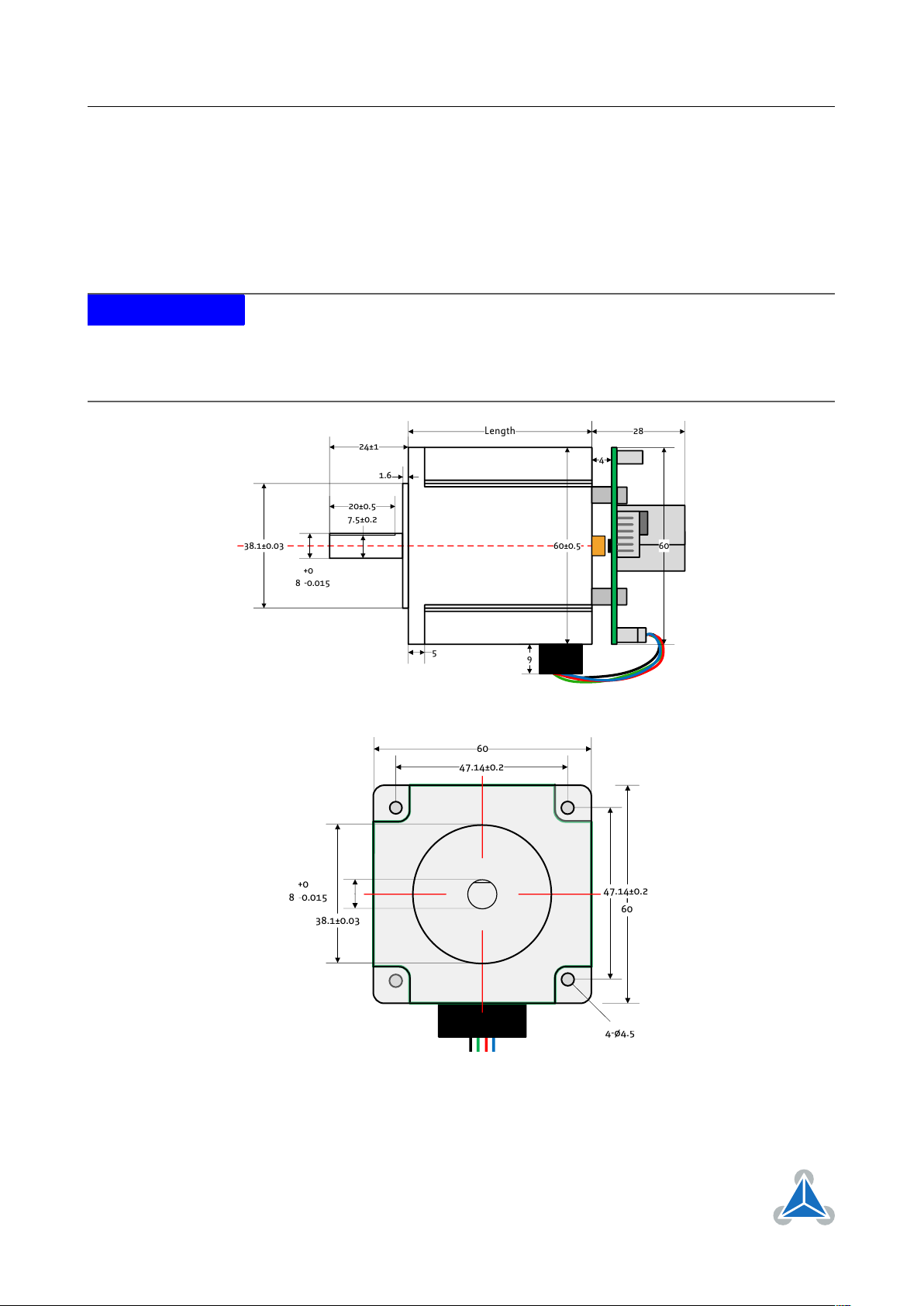
3.2 PD60-3-1260 and PD60-4-2-1260 Dimensions
The PD60-3-1260 and PD60-4-1260 include one NEMA24 / 60mm stepper motors with 2.8A RMS rated coil
current with the same TMCM-1260 controller / driver electronics mounted on its backside and integrated
sensOstep™encoder. The PD60-3-1260 uses the QSH6018-65-28-210 stepper motor with 2.1Nm holding
torque and the PD60-4-1260 uses the QSH6018-86-28-310 stepper motor with 3.1Nm holding torque.
Please see also stepper motor manuals and TMCM-1260 hardware and firmware manuals for more details.
NOTICE
Note:
In order to make proper use of the integrated sensOstep™encoder (the
sensor IC is placed on the bottom of the pcb) the TMCM-1260 electronics should
not be removed/moved relative to the motor. In case the integrated encoder
feature is not used, the electronics may be moved or even removed from the
motor and placed somewhere else according to application requirements.
Length of the stepper motor “body” itsself is 65mm for the PD60-3-1260 and 86mm for the PD60-4-1260.
©2018 TRINAMIC Motion Control GmbH & Co. KG, Hamburg, Germany
Terms of delivery and rights to technical change reserved.
Download newest version at www.trinamic.com
Page 10

PD57/60-x-1260 Hardware Manual • Hardware Version V1.10 | Document Revision V1.00 • 2018-03-29
10 / 38
3.3 Stepper motor
Main characteristics of the four different motors available as part of the PD57-x-1260 and PD60-x-1260
PANdrive™:
Specifications Unit PD57-1-1260 PD57-2-1260 PD60-3-1260 PD60-4-1260
Step angle ° 1.8 1.8 1.8 1.8
Step angle accuracy % +/-5 +/-5 +/-5 +/-5
Ambient temperature °C -20. . . +50 -20. . . +50 -20. . . +50 -20. . . +50
Max. motor temperature °C 80 80 80 80
Shaft radial play (450g load)
mm 0.02 0.02 0.02 0.02
Shaft axial play (450g load) mm 0.08 0.08 0.08 0.08
Max radial force (20mm
N 57 57 57 57
from front flange)
Max axial force N 15 15 15 15
Rated voltage V 2.0 2.3 3.36 4.17
Rated phase current A 2.8 2.8 2.8 2.8
Phase resistance at 20°C Ω 0.7 0.83 1.2 1.5
Phase inductance (typ.) mH 1.4 2.2 4.6 6.8
Holding torque Nm 0.55 1.01 2.1 3.1
Insulation class B B B B
Rotor inertia g cm
2
120 275 570 840
Weight kg 0.45 0.65 1.2 1.4
Table 3: NEMA23 / 57mm and NEMA24 / 60mm stepper motor technical data
©2018 TRINAMIC Motion Control GmbH & Co. KG, Hamburg, Germany
Terms of delivery and rights to technical change reserved.
Download newest version at www.trinamic.com
Page 11

PD57/60-x-1260 Hardware Manual • Hardware Version V1.10 | Document Revision V1.00 • 2018-03-29
11 / 38
3.4 Integrated sensOstep™ encoder
The PD57/60-x-1260 PANdrives offer integrated sensOstep™encoders based on hall sensor technology.
As the name “sensOstep™“ already indicates intended use of this type of compact and highly integrated
encoder is step loss detection of motor movements. As soon as the motor has been moved to a new
location the position may be verified using this encoder feedback. In case the stepper motor has lost one
or multiple steps during movement e.g. due to overload / any obstacle encountered during movement
the motor axes will jump for at least one electrical period / 4 full steps. This can be detected using the
integrated encoder. In addition, step losses may be already detected during motor movements using the
“deviation” setting available as part of the TMCL firmware (see PD57/60-x-1260 / TMCM-1240 firmware
manual for more details).
While the encoder offers 10bit (1024 steps) resolution per motor revolution the absolute position information is less accurate and depends on the displacement of the hall sensor based encoder IC relative to the
magnet and motor axis among other factors. Every PANdrive™has been tested for maximum deviation
of +/- 5 encoder steps (static performance) relative to commanded microstep target position during final
tests after assembly at our factory. This will ensure more than adequate performance of the integrated
sensOstep™ encoder for step loss detection during motor movements.
NOTICE
NOTICE
Do not disassemble PANdrive™ when using integrated encoder
In order to
make proper use of the integrated sensOstep™encoder (the sensor IC is placed
on the bottom center of the pcb) the TMCM-1260 electronics should not be
removed/moved relative to the motor! Otherwise encoder performance might
suffer / not work.
Note: In case the integrated encoder feature is not used, the TMCM-1260
electronics may be moved or even removed from the motor and placed
somewhere else according to application requirements.
Keep the electronics free of (metal) particles!
The integrated sensOstep
encoder uses a magnet at the end of the motor axis in order to monitor position
of the motor axis. The magnet naturally attracts especially tiny metal particles.
These particles might be held on the top side of the PCB and even worse start
moving in accordance with the rotating magnetic field as soon as the motor starts
moving. This might lead to shorts of electronic contacts / wires on the board
and totally erratic behavior of the module! Use compressed air for cleaning the
module if necessary (especially in prototype setups).
In order to prevent shorts and better protect the electronics the TMCM-1260
printed circuit board is coated after assembly of components.
™
©2018 TRINAMIC Motion Control GmbH & Co. KG, Hamburg, Germany
Terms of delivery and rights to technical change reserved.
Download newest version at www.trinamic.com
Page 12

PD57/60-x-1260 Hardware Manual • Hardware Version V1.10 | Document Revision V1.00 • 2018-03-29
I/O
RS485 + CAN
1 5
USB
1
8
Motor
14
1
4
14
12 / 38
4 Connectors
The PD57/60-x-1260 offers six connectors altogehter. There is one power supply connector and two
interface connectors - one with five pins for RS485 and CAN and a dedicated micro-USB connector. All
other inputs and outputs are concentrated on one 8 pin connector. Furthermore, there is one connection
for the stepper motor with four pins with a choice between two connectors with different size, pitch and
current rating. While the smaller one supports motor currents up-to 3A RMS (half the max. current of the
module) the larger supports the full current (6A RMS).
NOTICE
Start with power supply OFF and do not connect or disconnect motor during operation!
Motor cable and motor inductivity might lead to voltage spikes
when the motor is (dis)connected while energized. These voltage spikes might
exceed voltage limits of the driver MOSFETs and might permanently damage
them. Therefore, always switch off / disconnect power supply or at least disable
driver stage before connecting / disconnecting motor.
Figure 1: PD57/60-x-1260 connectors
Connector Types and Mating Connectors
Connector Connector type on-board Mating connector type
Power JST B4P-VH
(JST VH series, 4pins, 3.96mm pitch)
Motor JST JST B4P-VH
(JST VH series, 4pins, 3.96mm pitch)
or
JST JST B4B-EH-A
(JST EH series, 4pins, 2.5mm pitch)
RS485+CAN JST B5B-PH-K-S
(JST PH series, 5pins, 2mm pitch)
©2018 TRINAMIC Motion Control GmbH & Co. KG, Hamburg, Germany
Terms of delivery and rights to technical change reserved.
Download newest version at www.trinamic.com
Connector housing: JST VHR-4N
Contacts: JST SVH-21T-P1.1
Wire: 0.83mm2, AWG 18
Connector housing: JST VHR-4N
Contacts: JST SVH-21T-P1.1
Wire: 0.83mm2, AWG 18
or
Connector housing: JST EHR-4
Contacts: JST SEH-001T-P0.6
Wire: 0.33mm2, AWG 22
Connector housing: JST PHR-5
Contacts: JST SPH-002T-P0.5S
Wire: 0.22mm2, AWG 24
Page 13

PD57/60-x-1260 Hardware Manual • Hardware Version V1.10 | Document Revision V1.00 • 2018-03-29
Connector Connector type on-board Mating connector type
USB USB-micro B female connector USB-micro B male connector
13 / 38
I/O JST B8B-PH-K-S
(JST PH series, 8pins, 2mm pitch)
Connector housing: JST PHR-8
Contacts: JST SPH-002T-P0.5S
Wire: 0.22mm2, AWG 24
Table 4: Connector Types and Mating Connectors of the PD57/60-x-1260
4.1 Power Supply Input Connector
The PD57/60-x-1260 offers one 4pin JST VH series power supply input connector. In addition to main
power supply input and related ground connection this connector offers a separate logic supply input
with the option to keep the on-board logic alive while the driver stage is switched off. It is not necesary to
connect the logic supply input in case separate supplies are not required as the main power supply input
will always supply power to the driver stage and the logic part.
The power supply input connector offers a driver enable input. This input has to be connected to any
voltage above 3.5V up-to max. supply voltage of 54V in order to enable the driver stage. Leaving this pin
unconnected or connected to ground (voltage below 2.4V) will disable the driver stage regardless of any
settings in software. This input may be connected to main power supply input permanently in case an
enable input in hardware is not required.
Power Supply Connector Pin Assigment
Pin Label Direction Description
1 GND Power (GND) Common system supply and signal ground
2 V
MAIN
Power (input) Main power supply input for the driver and on-board logic
3 Enable Digital input
4 V
LOGIC
Power (input) Optional separate power supply input for the on-board logic
Table 5: Power Supply Connector Pin Assignment
NOTICE
Do not connect or disconnect motor during operation!
tor inductivity might lead to voltage spikes when the motor is (dis)connected
while energized. These voltage spikes might exceed voltage limits of the driver
MOSFETs and might permanently damage them. Therefore, always switch off
/ disconnect power supply or at least disable driver stage before connecting /
disconnecting motor.
NOTICE
NOTICE
Take care of polarity, wrong polarity can destroy the board!
Connect Enable pin to voltage >3.5V in order to enable motor movements!
12. . . 54V
Driver enable input. A voltage above 3.5V is required here
in order to enable the on-board stepper motor driver. This
input maybe connected to main power supply input in order
to enable the driver stage.
12. . . 54V
Motor cable and mo-
©2018 TRINAMIC Motion Control GmbH & Co. KG, Hamburg, Germany
Terms of delivery and rights to technical change reserved.
Download newest version at www.trinamic.com
Page 14

PD57/60-x-1260 Hardware Manual • Hardware Version V1.10 | Document Revision V1.00 • 2018-03-29
14 / 38
4.2 Motor Connector
Two four pin motor connectors are available. Either of them can be used for connecting a bipolar stepper
motor. Both connectors are connected to the same driver stage therefore, just one connector should
be used at the same time. While the more compact 4pin JST EH series connector is suitable for motor
currents up-to 3A RMS the larger JST VH series connector is able to support all motor current up-to 6A
RMS (limit of the unit).
Motor Connector Pin Assignment
Pin Label Direction Description
1 B1 out Pin 1 of motor coil B
2 B2 out Pin 2 of motor coil B
3 A1 out Pin 1 of motor coil A
4 A2 out Pin 2 of motor coil A
Table 6: Motor Connector Pin Assignment
NOTICE
NOTICE
NOTICE
Connect just one motor connector at the same time!
connected to the same driver stage.
Do not connect or disconnect motor during operation!
tor inductivity might lead to voltage spikes when the motor is (dis)connected
while energized. These voltage spikes might exceed voltage limits of the driver
MOSFETs and might permanently damage them. Therefore, always switch off
/ disconnect power supply or at least disable driver stage before connecting /
disconnecting motor.
Do not mix-up power supply connector and the larger motor connector!
Both connectors are
Motor cable and mo-
4.3 RS485 + CAN Connector
For serial communication the PD57/60-x-1260 offers selection between RS485, CAN and USB interfaces.
While the USB interface is available for configuration and service of the board, mainly (e.g. parameter
settings, firmware updates) a 5-pin JST PH series connector offers 2-wire RS485 and CAN interfaces for in
system communication.
NOTICE
Due to hardware ressource sharing USB and CAN communication interfaces are
not available at the same time. As soon as USB is physically attached to a host or
hub the CAN interface will be switched off.
RS485 + CAN Connector Pin Assignment
Pin Label Direction Description
1 GND Power (GND) Common system supply and signal ground
2 RS485+ Bidirectional RS485 interface, diff. signal (non-inverting)
3 RS485- Bidirectional RS485 interface, diff. signal (inverting)
©2018 TRINAMIC Motion Control GmbH & Co. KG, Hamburg, Germany
Terms of delivery and rights to technical change reserved.
Download newest version at www.trinamic.com
Page 15

PD57/60-x-1260 Hardware Manual • Hardware Version V1.10 | Document Revision V1.00 • 2018-03-29
15 / 38
Pin Label Direction Description
4 CAN_H Bidirectional CAN interface, diff. signal (non-inverting)
5 CAN_L Bidirectional CAN interface, diff. signal (inverting)
Table 7: RS485 + CAN Connector Pin Assignment
4.4 USB Connector
For serial communication the PD57/60-x-1260 offers selection between RS485, CAN and USB interfaces.
The USB interface via on-board micro-USB connector (type B) is available for configuration and service
of the board, mainly (e.g. parameter settings, firmware updates). The USB device interface supports
full speed (12Mbit/s) communication and supports bus powered and self-powered operation. During
bus-powered operation the low voltage logic part of the board will be powered, only. This includes the
microcontroller and the non-volatile memory and therefore allows parameter settings and firmware
updates of the board using a standard USB cable, only. Of course, for any motor movement main supply
via supply input connector is required.
NOTICE
Due to hardware ressource sharing USB and CAN communication interfaces are
not available at the same time. As soon as USB is physically attached to a host or
hub the CAN interface will be switched off.
USB Connector Pin Assignment
Pin Label Direction Description
1 VBUS Power (+5V) USB +5V nom. power supply input
2 D- Bidirectional USB interface, diff. signal (inverting)
3 D+ Bidirectional USB interface, diff. signal (inverting)
4 ID Input connected to GND (via 100k resistor)
5 GND Power (GND) Common system supply and signal ground
Table 8: USB Connector Pin Assignment
4.5 I/O Connector
The PD57/60-x-1260 offers several inputs (two of them optically isolated) and one digital (open-drain) output. The inputs include support for stop switches (left and right), home switch, step/direction, incremental
A/B channel encoder and analog (0. . . +10V) input. All this functionality is available via one 8pin JST PH
series I/O connector.
USB Connector Pin Assignment
Pin Label Direction Description
1 GND Power (GND) Common system supply and signal ground
2 IN0/HOME Input Analog input (0. . . +10V)
HOME switch input
+24V tolerant, programmable (separate) pull-up to +5V
©2018 TRINAMIC Motion Control GmbH & Co. KG, Hamburg, Germany
Terms of delivery and rights to technical change reserved.
Download newest version at www.trinamic.com
Page 16

PD57/60-x-1260 Hardware Manual • Hardware Version V1.10 | Document Revision V1.00 • 2018-03-29
Green LEDRed LED
Pin Label Direction Description
3 IN1/ENC_A Input General purpose digital input
Incremental encoder input channel A
+24V tolerant, programmable pull-up (for IN1/IN2 together) to +5V
3 IN2/ENC_B Input General purpose digital input
Incremental encoder input channel B
+24V tolerant, programmable pull-up (for IN1/IN2 together) to +5V
5 STOP_L/STEP Input STOP left switch input
STEP pulse input
input optically isolated, +24V compatible
6 STOP_R/DIR Input STOP right switch input
DIR input
input optically isolated, +24V compatible
16 / 38
7 ISO_COM Power
Common positive (+24V_ISO) or negative (GND_ISO) isolated
supply input for optically isolated inputs
8 OUT0 Output (OD)
Open-Drain output. Output will be pulled low when activated.
Voltages up-to logic supply input level (or main supply input in
case separate logic supply is not used) are supported here. Max.
continuous pull-down current: 100mA
Table 9: I/O Connector Pin Assignment
All pins marked light green offer functional isolation towards main supply input. In case this is not required
ISO_COM may be connected to main ground or supply input, of course. The opto-couppler used are AC
types. This way, either high side switches or low side switches for both inputs are supported.
5 On-Board LEDs
The board offers two LEDs in order to indicate board status. The function of both LEDs is dependent on the
firmware version. With standard TMCL firmware the green LED should be flashing slowly during operation
and the red LED should be off. When there is no valid firmware programmed into the board or during
firmware update the red and green LEDs are permanently switched on. During reset to factory default
values the green LED will be flashing fast. With CANopen firmware both LEDs are switched on/off/flashing
according to standard defintion.
Figure 2: PD57/60-x-1260 LEDs
©2018 TRINAMIC Motion Control GmbH & Co. KG, Hamburg, Germany
Terms of delivery and rights to technical change reserved.
Download newest version at www.trinamic.com
Page 17

PD57/60-x-1260 Hardware Manual • Hardware Version V1.10 | Document Revision V1.00 • 2018-03-29
Short these two pads
17 / 38
6 Reset to Factory Defaults
It is possible to reset all settings in firmware for the PD57/60-x-1260 to factory defaults without establishing
a working communication connection. This might be helpful in case communication parameters of the
preferred interface have been set to unknown values or got lost.
For this procedure two pads on the bottom side of the module have to be shorted (electrically connected
with each other) during power-on.
Please perform the following steps:
1. Switch power supply OFF (and disconnect USB cable if applicable)
2. Short CLK and DIO pads of programming pads on bottom of pcb (see figure ??)
3. Switch power supply ON again (or connect USB again if applicable)
4. Wait until the on-board red and green LEDs start flashing fast (this might take a while)
5. Switch power supply OFF again (and disconnect USB cable if applicable)
6. Remove short between pads
7.
After switching power supply ON again (and / or connecting USB cable) all permanent settings have
been restored to factroy defaults
Figure 3: Reset to factory default settings
©2018 TRINAMIC Motion Control GmbH & Co. KG, Hamburg, Germany
Terms of delivery and rights to technical change reserved.
Download newest version at www.trinamic.com
Page 18

PD57/60-x-1260 Hardware Manual • Hardware Version V1.10 | Document Revision V1.00 • 2018-03-29
100nF
10k
22k
2k2
+3V3
microcontroller
microcontroller
IN0
+5V
TMCM-1260
pull-up
disabled
V
18 / 38
7 I/Os
The I/O connector (8pin JST PH series) offers one analog input, two non-isolated digital inputs with
integrated pull-ups (programmable) and two optically isolated inputs. All inputs can be used for different
purposes explained in more detail in the following subsections.
7.1 Analog input IN0
The PD57/60-x-1260 offers one analog input. The analog input voltage range is approx. 0..+10V. For
voltages above +10V saturation takes place but, up-to 30V higher voltages are tolerated without destroying
the input. For analog to digital conversion the integrated ADC of the on-board microcontroller is used.
Resolution of this converter is 12bit (0..4095).
Figure 4: Analog input IN0
The analog input can be used as digital input, also. There is an integrated pull-up to +5V which can be
switched on of off in software. When using this input as anlog input the pull-up should be usually switched
off.
7.2 Digital inputs IN1 and IN2
The PD57/60-x-1260 offers two digital inputs IN1 and IN2 which accept signals between 0 and 30V with
voltages above approx. 2.9V recognized as logical ’1’ and below 1V as logical ’0’. Both inputs offer intergated
pull-ups to +5V which can be switched on or off in software (always together). When using the inputs with
low-side switches (connected to GND), pull-ups usually should be switched on (default). In case high-side
switches are used the pull-ups must be switched off. For push-pull signals the pull-ups may be either
switched on or off.
©2018 TRINAMIC Motion Control GmbH & Co. KG, Hamburg, Germany
Terms of delivery and rights to technical change reserved.
Download newest version at www.trinamic.com
Page 19

PD57/60-x-1260 Hardware Manual • Hardware Version V1.10 | Document Revision V1.00 • 2018-03-29
33pF
22k
10k
2k2
+3V3
microcontroller
microcontroller
IN1
IN2
+5V
TMCM-1260
or
pull-up
enabled
or
pull-up
disabled
+5V...24V
+5V
680
6k8
2k2
+3V3
microcontroller
TMCM-1260
STOP_L,
STOP_R
ISO_COM
+24V_ISO
GND_ISO
or
+24V_ISO
GND_ISO
19 / 38
Figure 5: Digital inputs IN1 and IN2
7.3 HOME/STOP_L/STOP_R switch inputs
The PD57/60-x-1260 offers two optically isolated inputs which can be used as left (STOP_L) and right
(STOP_R) stop switch inputs. When enabled in software the STOP_L switch input will stop motor movement
in negative direction (step counter decreasing) while activated. Likewise the STOP_R switch input will stop
motor movement in positive direction (step counter increasing) while activated.
Figure 6: Stop switch inputs
A separated / isolated supply may be used for the switches - as indicated in the drawing (+24V_ISO and
related GND_ISO) - but, same supply as for the PD57/60-x-1260 can be used, also, of course.
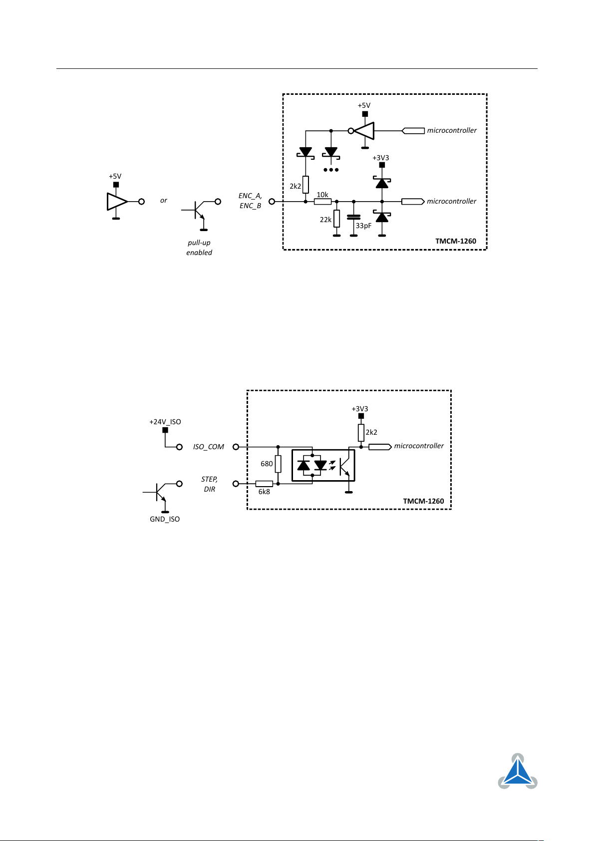
7.4 External incremental encoder input
The PD57/60-x-1260 offers an integrated hall-sensor based magnet encoder. In addition, an external
incremental A/B encoder may be connected to the two digital inputs IN1 and IN2. Encoder with push-pull
signals (e.g. +5V TTL) and open-drain output signals are supported (single-ended). For open-drain outputs
the internal pull-ups should be activated in software (default mode).
©2018 TRINAMIC Motion Control GmbH & Co. KG, Hamburg, Germany
Terms of delivery and rights to technical change reserved.
Download newest version at www.trinamic.com
Page 20
PD57/60-x-1260 Hardware Manual • Hardware Version V1.10 | Document Revision V1.00 • 2018-03-29
33pF
22k
10k
2k2
+3V3
microcontroller
microcontroller
ENC_A,
ENC_B
+5V
TMCM-1260
or
+5V
pull-up
enabled
680
6k8
2k2
+3V3
microcontroller
TMCM-1260
STEP,
DIR
ISO_COM
+24V_ISO
GND_ISO
20 / 38
Figure 7: External encoder input
7.5 Step/Direction inputs
The PD57/60-x-1260 may be used as driver with an external motion controller. In this case the Step/Direction output signals of the external motion controller may be connected to the optically isolated Step/Dir
inputs of the PD57/60-x-1260. Please note that these signals should be 24V signals. For lower voltage
signals a simple small signal transistor maybe inserted as level converter.
Figure 8: Step/Direction input
Due to limitations of the opto-isolators the maximum step frequency of these inputs is limited to around
20kHz. For higher motor speed the step interpolator of the driver stage should be activated or the
microstep resolution reduced (default 256 microsteps per fullstep).
©2018 TRINAMIC Motion Control GmbH & Co. KG, Hamburg, Germany
Terms of delivery and rights to technical change reserved.
Download newest version at www.trinamic.com
Page 21

PD57/60-x-1260 Hardware Manual • Hardware Version V1.10 | Document Revision V1.00 • 2018-03-29
c:>
node
1
node
n
- 1
node
n
Host
Slave Slave Slave
RS485
termination
resistor
(120 Ohm)
termination
resistor
(120 Ohm)
}
keep distance as
short as possible
21 / 38
8 Communication
8.1 RS485
For remote control and communication with a host system the PD57/60-x-1260 provides a two wire RS485
bus interface. For proper operation the following items should be taken into account when setting up an
RS485 network:
1. BUS STRUCTURE:
The network topology should follow a bus structure as closely as possible. That is, the connection
between each node and the bus itself should be as short as possible. Basically, it should be short
compared to the length of the bus.
Figure 9: RS485 bus structure with termination resistors
2. BUS TERMINATION:
Especially for longer busses and/or multiple nodes connected to the bus and/or high communication
speeds, the bus should be properly terminated at both ends. The PD57/60-x-1260 does not integrate
any termination resistor. Therefore, 120 Ohm termination resistors at both ends of the bus have to
be added externally.
3. NUMBER OF NODES:
The RS485 electrical interface stadard (EIA-485) allows up to 32 nodes to be connected to a single
bus. The bus transceiver used on the PD57/60-x-1260 units (SN65HVD1781D) offers a significantly
reduced bus load compared to the standard and allows a maximum of 255 units to be connected
to a single RS485 bus using standard TMCL firmware. Please note: usually it cannot be expected to
get reliable communication with the maximum number of nodes connected to one bus and maximum
supported communication speed at the same time. Instead, a compromise has to be found between bus
cable length, communication speed and number of nodes.
4. COMMUNICATION SPEED:
The maximum RS485 communication speed supported by the PD57/60-x-1260 hardware is 1Mbit/s.
Factory default is 9600 bit/s. Please see separate PD57/60-x-1260 TMCL firmware manual for
information regarding other possible communication speeds below the upper hardware limit.
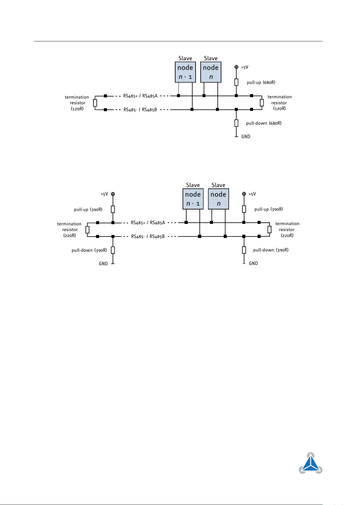
5. NO FLOATING BUS LINES:
Avoid floating bus lines while neither the host/master nor one of the slaves along the bus line
is transmitting data (all bus nodes switched to receive mode). Floating bus lines may lead to
communication errors. In order to ensure valid signals on the bus it is recommended to use a resistor
network connecting both bus lines to well defined logic levels.
There are actually two options which can be recommended: Add resistor (bias) network on one side
of the bus, only (120R termination resistor still at both ends):
©2018 TRINAMIC Motion Control GmbH & Co. KG, Hamburg, Germany
Terms of delivery and rights to technical change reserved.
Download newest version at www.trinamic.com
Page 22
PD57/60-x-1260 Hardware Manual • Hardware Version V1.10 | Document Revision V1.00 • 2018-03-29
node
n - 1
node
n
Slave Slave
termination
resistor
(120R)
+5V
GND
pull-up (680R)
pull-down (680R)
RS485- / RS485B
termination
resistor
(120R)
RS485+ / RS485A
node
n - 1
node
n
Slave Slave
termination
resistor
(220R)
+5V
GND
pull-up (390R)
pull-down (390R)
RS485- / RS485B
RS485+ / RS485A
termination
resistor
(220R)
+5V
GND
pull-up (390R)
pull-down (390R)
Figure 10: RS485 bus lines with resistor (bias) network on one side, only
Or add resistor network at both ends of the bus (like Profibus™ termination):
22 / 38
Figure 11: RS485 bus lines with Profibus™recommended line termination
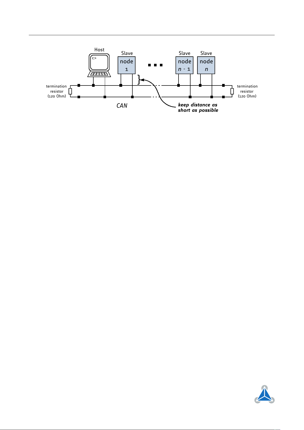
8.2 CAN
For remote control and communication with a host system the PD57/60-x-1260 provides a CAN bus
interface. Please note that the CAN interface is not available in case USB is connected. For proper
operation the following items should be taken into account when setting up a CAN network:
1. BUS STRUCTURE:
The network topology should follow a bus structure as closely as possible. That is, the connection
between each node and the bus itself should be as short as possible. Basically, it should be short
compared to the length of the bus.
©2018 TRINAMIC Motion Control GmbH & Co. KG, Hamburg, Germany
Terms of delivery and rights to technical change reserved.
Download newest version at www.trinamic.com
Page 23
PD57/60-x-1260 Hardware Manual • Hardware Version V1.10 | Document Revision V1.00 • 2018-03-29
c:>
node
1
node
n
- 1
node
n
Host
Slave Slave Slave
CAN
termination
resistor
(120 Ohm)
termination
resistor
(120 Ohm)
}
keep distance as
short as possible
Figure 12: CAN bus structure with termination resistors
2. BUS TERMINATION:
Especially for longer busses and/or multiple nodes connected to the bus and/or high communication
speeds, the bus should be properly terminated at both ends. The PD57/60-x-1260 does not integrate
any termination resistor. Therefore, 120 Ohm termination resistors at both ends of the bus have to
be added externally.
3. BUS TERMINATION:
The bus transceiver used on the PD57/60-x-1260 units (TJA1051T) supports at least 110 nodes under
optimum conditions. Practically achievable number of nodes per CAN bus highly depend on bus
length (longer bus -> less nodes) and communication speed (higher speed -> less nodes).
23 / 38
©2018 TRINAMIC Motion Control GmbH & Co. KG, Hamburg, Germany
Terms of delivery and rights to technical change reserved.
Download newest version at www.trinamic.com
Page 24
PD57/60-x-1260 Hardware Manual • Hardware Version V1.10 | Document Revision V1.00 • 2018-03-29
24 / 38
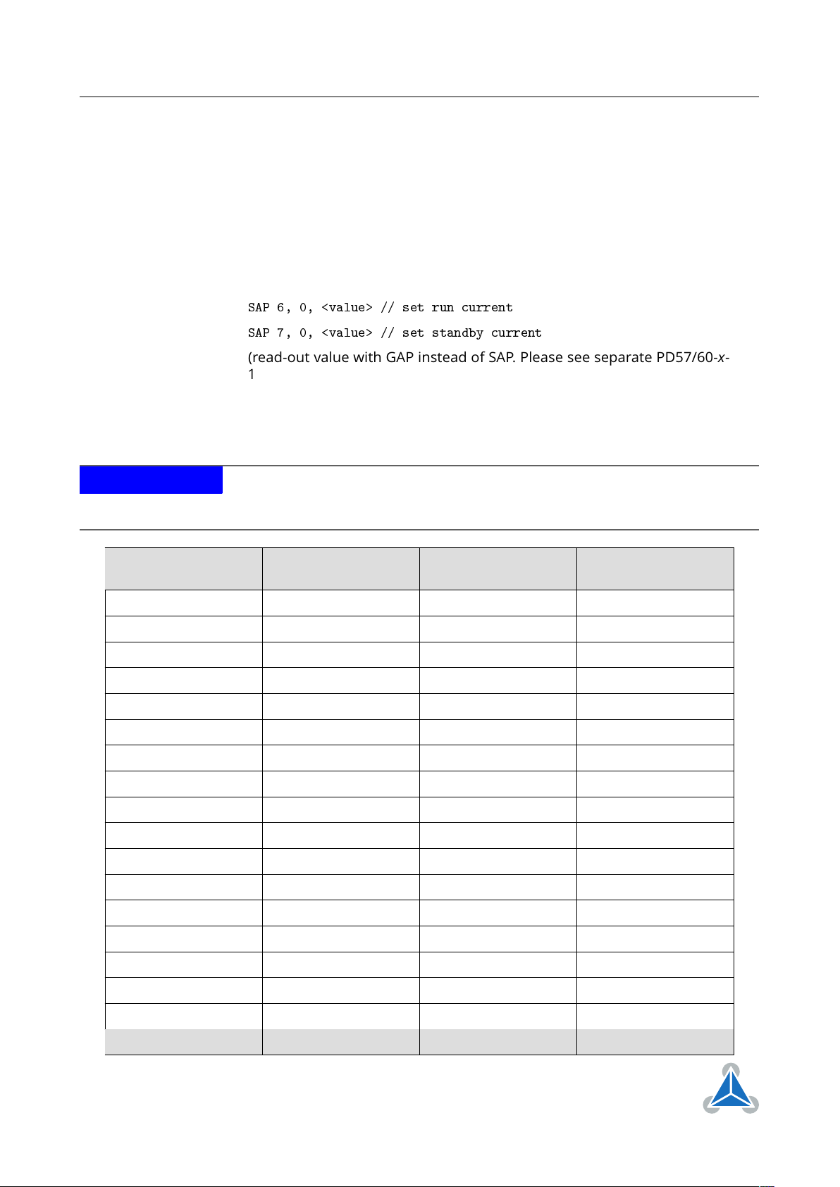
9 Motor driver current
The on-board stepper motor driver operates current controlled. The driver current may be programmed
in software with 32 effective scaling steps in hardware.
Explanation of different columns in table below:
Motor current setting in software
(TMCL)
These are the values for TMCL axis parameter 6 (motor run current) and
7 (motor standby current). They are used to set the run / standby current
using the following TMCL commands:
SAP 6, 0, <value> // set run current
SAP 7, 0, <value> // set standby current
(read-out value with GAP instead of SAP. Please see separate PD57/60-x1260 firmware manual for further information)
Motor current I
Resulting motor current based on motor current setting
RMS
[A]
NOTICE
All motor current settings marked gray in table below will violate motor specification (rated current). Usually, they should not be used - at least not for prolonged
time as the motor might overheat and get damaged permanently!
Motor current setting
in software (TMCL)
Current scaling step
(CS)
Motor current I
peak
COIL
[A]
Motor current I
RMS
0. . . 7 0 0.254 0.180
8. . . 15 1 0.508 0.359
16. . . 23 2 0.762 0.539
COIL
[A]
24. . . 31 3 1.016 0.718
32. . . 39 4 1.270 0.898
40. . . 47 5 1.523 1.077
48. . . 55 6 1.777 1.257
56. . . 63 7 2.031 1.436
64. . . 71 8 2.285 1.616
72. . . 79 9 2.539 1.795
80. . . 87 10 2.793 1.975
88. . . 95 11 3.047 2.154
96. . . 103 12 3.301 2.334
104. . . 111 13 3.555 2.514
112. . . 119 14 3.809 2.693
120. . . 127 15 4.063 2.873
128. . . 135 16 4.316 3.052
136. . . 143 17 4.570 3.232
©2018 TRINAMIC Motion Control GmbH & Co. KG, Hamburg, Germany
Terms of delivery and rights to technical change reserved.
Download newest version at www.trinamic.com
Page 25

PD57/60-x-1260 Hardware Manual • Hardware Version V1.10 | Document Revision V1.00 • 2018-03-29
25 / 38
Motor current setting
in software (TMCL)
Current scaling step
(CS)
Motor current I
peak
COIL
[A]
Motor current I
RMS
144. . . 151 18 4.824 3.411
152. . . 159 19 5.078 3.591
160. . . 167 20 5.332 3.770
168. . . 175 21 5.586 3.950
176. . . 183 22 5.840 4.129
184. . . 191 23 6.094 4.309
192. . . 199 24 6.348 4.488
200. . . 207 25 6.602 4.668
208. . . 215 26 6.855 4.848
216. . . 223 27 7.109 5.027
224. . . 231 28 7.363 5.207
232. . . 239 29 7.617 5.386
240. . . 247 30 7.871 5.566
248. . . 255 31 8.125 5.745
COIL
[A]
Table 11: Available motor current settings
In addition to the settings in the table the motor current may be switched off completely (free-wheeling)
using axis parameter 204 (see PD57/60-x-1260 firmware manual).
©2018 TRINAMIC Motion Control GmbH & Co. KG, Hamburg, Germany
Terms of delivery and rights to technical change reserved.
Download newest version at www.trinamic.com
Page 26

PD57/60-x-1260 Hardware Manual • Hardware Version V1.10 | Document Revision V1.00 • 2018-03-29
10 Torque curves
10.1 PD57-1-1260 Torque Curve
26 / 38
Figure 13: PD57-1-1260 torque vs. velocity 24V / 2.8A, 256µsteps
Figure 14: PD57-1-1260 torque vs. velocity 48V / 2.8A, 256µsteps
©2018 TRINAMIC Motion Control GmbH & Co. KG, Hamburg, Germany
Terms of delivery and rights to technical change reserved.
Download newest version at www.trinamic.com
Page 27

PD57/60-x-1260 Hardware Manual • Hardware Version V1.10 | Document Revision V1.00 • 2018-03-29
10.2 PD57-2-1260 Torque Curve
27 / 38
Figure 15: PD57-2-1260 torque vs. velocity 24V / 2.8A, 256µsteps
Figure 16: PD57-2-1260 torque vs. velocity 48V / 2.8A, 256µsteps
©2018 TRINAMIC Motion Control GmbH & Co. KG, Hamburg, Germany
Terms of delivery and rights to technical change reserved.
Download newest version at www.trinamic.com
Page 28

PD57/60-x-1260 Hardware Manual • Hardware Version V1.10 | Document Revision V1.00 • 2018-03-29
10.3 PD60-3-1260 Torque Curve
Figure 17: PD60-3-1260 torque vs. velocity 24V / 2.8A, 256µsteps
28 / 38
Figure 18: PD60-3-1260 torque vs. velocity 48V / 2.8A, 256µsteps
©2018 TRINAMIC Motion Control GmbH & Co. KG, Hamburg, Germany
Terms of delivery and rights to technical change reserved.
Download newest version at www.trinamic.com
Page 29

PD57/60-x-1260 Hardware Manual • Hardware Version V1.10 | Document Revision V1.00 • 2018-03-29
10.4 PD60-4-1260 Torque Curve
Figure 19: PD60-4-1260 torque vs. velocity 24V / 2.8A, 256µsteps
29 / 38
Figure 20: PD60-4-1260 torque vs. velocity 48V / 2.8A, 256µsteps
©2018 TRINAMIC Motion Control GmbH & Co. KG, Hamburg, Germany
Terms of delivery and rights to technical change reserved.
Download newest version at www.trinamic.com
Page 30

PD57/60-x-1260 Hardware Manual • Hardware Version V1.10 | Document Revision V1.00 • 2018-03-29
…54V DC
ARM
Cortex
M
3
TM
microcontroller
EEPROM
6
I/Os
Step
Motor
RS
485
Driver
Stage
Energy Efficient
Driver
TMC
262
Motion
Controller
SPI
USB
SPI
CAN
/
DC
V
sensOstep™
Encoder
SPI
3V3
_
/
R,S
/
,
PD
1260
2
1260
6031260
PD
6041260
QSH
5718
4128055
QSH
5718
51
28
101
QSH
60186528
210
60188628
310
1260
30 / 38
11 Functional Description
The PD57/60-x-1260 is a full mechatronic solution including a NEMA23 or NEMA24 flange size bipolar
stepper motor. It includes the controller / driver electronics TMCM-1260 and a choice between four
different NEMA 23 / 57mm and NEMA24 / 60mm flange size bipolar hybrid stepper motors with different
length and torque. The PD57/60-x-1260 can be controlled via USB, RS485 or CAN serial interfaces. There
are three general purpose digital inputs which can be used, also as STOP_L / STOP_R / HOME switch inputs
(for reference movements, as end switches etc. depending on firmware, mode and configuration) or for
connecting an additional external encoder (incremental A/B/N). In addition, there is one dedicated analog
input for 0. . . +10V analog signals and two general-purpose outputs (one open-drain and one switchable
+5V supply output).
The PD57/60-x-1260 with TMCL™firmware option is supported by the PC based software development
environment TMCL-IDE for the Trinamic Motion Control Language (TMCL™). Using predefined TMCL™high
level commands like move to position a rapid and fast development of motion control applications is
guaranteed. Please refer to the PD57/60-x-1260 or TMCM-1260 firmware manuals for more information
about TMCL™ commands.
Communication trafic is kept low since all time critical operations, e.g. ramp calculation are performed on
board. Complete stand-alone or full remote control or anything in-between is possible. The firmware of the
module can be updated via the serial interface. As an alternative to TMCL, a CANopen firmware is available.
The PD57/60-x-1260 module contains the following main components:
• Microcontroller (ARM Cortex-M3™), responsible for overall control and communication
•
Highly integrated advanced stepper motor controller supporting linear and unique 6-points ramps in
hardware
•
Advanced stepper motor driver with stallGuard2™and coolStep™with MOSFET driver stage (8x
power N-MOSFETs for bipolar stepper motor)
• RS485, CAN and USB transceivers
• On-board voltage regulators (+5V and +3V3) required for supply of all on-board digital circuits
Figure 21: PD57/60-x-1260 block diagram
©2018 TRINAMIC Motion Control GmbH & Co. KG, Hamburg, Germany
Terms of delivery and rights to technical change reserved.
Download newest version at www.trinamic.com
Page 31

PD57/60-x-1260 Hardware Manual • Hardware Version V1.10 | Document Revision V1.00 • 2018-03-29
12 Operational Ratings and Characteristics
31 / 38
NOTICE
Never Exceed the absolute maximum ratings!
Keep the power supply voltage
below the upper limit of +54V! Otherwise the board electronics will seriously be
damaged! Especially, when the selected operating voltage is near the upper limit
a regulated power supply is highly recommended.
General Operational Ratings
Symbol Parameter Min Typ Max Unit
V
Power
I
Power
V
I
USB
USB
Power supply voltage 12 24. . . 48 54 V
Power supply current <<I
COIL_RMS
1.4 x I
COIL_RMS
Power supply via USB connector 5 V
Current withdrawn from USB supply when USB
43 mA
A
bus powered (no other supply connected)
I
COIL_PEAK
Motor coil current for sine wave
peak (chopper
0 8.4 A
regulated, adjustable via software)
I
COIL_RMS
T
ENV
Continuous motor current (RMS) 0 6 A
Environmental temperature at maximum rated
-30 40 °C
current (no forced cooling reaquired)
Table 12: General operational ratings of the module
Operational Ratings of the I/Os
Symbol Parameter Min Typ Max Unit
V
I
OUT0
OUT0
Voltage at open drain output OUT0 (switched off) 0 +V
Output sink current of open drain output OUT0
Power
100 mA
(switched on)
V
IN0/1/2
V
IN0
V
IN1/2_L
V
IN1/2_H
V
STOP_L/R_ON
Input voltage for IN0. . . IN2 0 0. . . +24 +30 V
Measurement range for analog input IN0 0 +10
1
Low level voltage for IN1 and IN2 (digital inputs) 1 V
High level voltage for IN1 and IN2 (digital inputs) 2.9 V
Switch-On opto-isolated inputs (voltage between
20-24 30 V
input and ISO_COM)
V
STOP_L/R_OFF
Switch-off opto-isolated inputs (voltage between
0 0-16 V
input and ISO_COM)
f
STEP/DIR
Max. frequency for step/direction opto-isolated
20 kHz
inputs
1
approx. 0. . . +10.56V at the analog input IN0 is translated to 0. . . 4095 (12bit ADC, raw values). Above approx. +10.56V the analog
input will saturate but, not being damaged (up-to VDD).
V
V
©2018 TRINAMIC Motion Control GmbH & Co. KG, Hamburg, Germany
Terms of delivery and rights to technical change reserved.
Download newest version at www.trinamic.com
Page 32

PD57/60-x-1260 Hardware Manual • Hardware Version V1.10 | Document Revision V1.00 • 2018-03-29
Operational Ratings of the I/Os
Symbol Parameter Min Typ Max Unit
Table 13: Operational ratings of I/Os
Operational Ratings of the RS485 Interface
Symbol Parameter Min Typ Max Unit
32 / 38
N
f
RS485
RS485
Number of nodes connected to single RS485 network 256
Max. speed for RS485 network 1Mbit/s
Table 14: Operational ratings of the RS485 interface
Operational Ratings of the CAN Interface
Symbol Parameter Min Typ Max Unit
N
f
CAN
CAN
Number of nodes connected to single CAN network >110
Max. speed for CAN network 1Mbit/s
Table 15: Operational ratings of the CAN interface
©2018 TRINAMIC Motion Control GmbH & Co. KG, Hamburg, Germany
Terms of delivery and rights to technical change reserved.
Download newest version at www.trinamic.com
Page 33

PD57/60-x-1260 Hardware Manual • Hardware Version V1.10 | Document Revision V1.00 • 2018-03-29
13 Abbreviations used in this Manual
Abbreviation Description
IDE Integrated Development Environment
LED Light Emmitting Diode
RMS Root Mean Square value
TMCL TRINAMIC Motion Control Language
Table 16: Abbreviations used in this Manual
33 / 38
©2018 TRINAMIC Motion Control GmbH & Co. KG, Hamburg, Germany
Terms of delivery and rights to technical change reserved.
Download newest version at www.trinamic.com
Page 34

PD57/60-x-1260 Hardware Manual • Hardware Version V1.10 | Document Revision V1.00 • 2018-03-29
14 Figures Index
34 / 38
1 PD57/60-x-1260 connectors . . . . . . 12
2 PD57/60-x-1260 LEDs . . . . . . . . . . 16
3 Reset to factory default settings . . . 17
4 Analog input IN0 . . . . . . . . . . . . 18
5 Digital inputs IN1 and IN2 . . . . . . . 19
6 Stop switch inputs . . . . . . . . . . . 19
7 External encoder input . . . . . . . . . 20
8 Step/Direction input . . . . . . . . . . 20
9
RS485 bus structure with termination
resistors . . . . . . . . . . . . . . . . . 21
10
RS485 bus lines with resistor (bias) net-
work on one side, only . . . . . . . . . 22
11
RS485 bus lines with Profibus™recommended
line termination . . . . . . . . . . . . . 22
12
CAN bus structure with termination
resistors . . . . . . . . . . . . . . . . . 23
13
PD57-1-1260 torque vs. velocity 24V /
2.8A, 256µsteps . . . . . . . . . . . . . 26
14
PD57-1-1260 torque vs. velocity 48V /
2.8A, 256µsteps . . . . . . . . . . . . . 26
15
PD57-2-1260 torque vs. velocity 24V /
2.8A, 256µsteps . . . . . . . . . . . . . 27
16
PD57-2-1260 torque vs. velocity 48V /
2.8A, 256µsteps . . . . . . . . . . . . . 27
17
PD60-3-1260 torque vs. velocity 24V /
2.8A, 256µsteps . . . . . . . . . . . . . 28
18
PD60-3-1260 torque vs. velocity 48V /
2.8A, 256µsteps . . . . . . . . . . . . . 28
19
PD60-4-1260 torque vs. velocity 24V /
2.8A, 256µsteps . . . . . . . . . . . . . 29
20
PD60-4-1260 torque vs. velocity 48V /
2.8A, 256µsteps . . . . . . . . . . . . . 29
21 PD57/60-x-1260 block diagram . . . . 30
©2018 TRINAMIC Motion Control GmbH & Co. KG, Hamburg, Germany
Terms of delivery and rights to technical change reserved.
Download newest version at www.trinamic.com
Page 35

PD57/60-x-1260 Hardware Manual • Hardware Version V1.10 | Document Revision V1.00 • 2018-03-29
15 Tables Index
35 / 38
1 TMCM-1260 Order Code . . . . . . . . 7
2 TMCM-1260 Cable Loom . . . . . . . . 7
3
NEMA23 / 57mm and NEMA24 /
60mm stepper motor technical data . 10
4
Connector Types and Mating Connec-
tors of the PD57/60-x-1260 . . . . . . 13
5
Power Supply Connector Pin Assignment
13
6 Motor Connector Pin Assignment . . 14
7
RS485 + CAN Connector Pin Assignment
15
8 USB Connector Pin Assignment . . . . 15
9 I/O Connector Pin Assignment . . . . 16
11 Available motor current settings . . . 25
12
General operational ratings of the
module . . . . . . . . . . . . . . . . . . 31
13 Operational ratings of I/Os . . . . . . 32
14
Operational ratings of the RS485 inter-
face . . . . . . . . . . . . . . . . . . . . 32
15
Operational ratings of the CAN interface
32
16 Abbreviations used in this Manual . . 33
17 Hardware Revision . . . . . . . . . . . 38
18 Document Revision . . . . . . . . . . . 38
©2018 TRINAMIC Motion Control GmbH & Co. KG, Hamburg, Germany
Terms of delivery and rights to technical change reserved.
Download newest version at www.trinamic.com
Page 36

PD57/60-x-1260 Hardware Manual • Hardware Version V1.10 | Document Revision V1.00 • 2018-03-29
36 / 38
16 Supplemental Directives
16.1 Producer Information
16.2 Copyright
TRINAMIC owns the content of this user manual in its entirety, including but not limited to pictures, logos,
trademarks, and resources.©Copyright 2018 TRINAMIC. All rights reserved. Electronically published by
TRINAMIC, Germany.
Redistributions of source or derived format (for example, Portable Document Format or Hypertext Markup
Language) must retain the above copyright notice, and the complete Datasheet User Manual documentation of this product including associated Application Notes; and a reference to other available
product-related documentation.
16.3 Trademark Designations and Symbols
Trademark designations and symbols used in this documentation indicate that a product or feature is
owned and registered as trademark and/or patent either by TRINAMIC or by other manufacturers, whose
products are used or referred to in combination with TRINAMIC’s products and TRINAMIC’s product documentation.
This Hardware Manual is a non-commercial publication that seeks to provide concise scientific and technical
user information to the target user. Thus, trademark designations and symbols are only entered in the
Short Spec of this document that introduces the product at a quick glance. The trademark designation
/symbol is also entered when the product or feature name occurs for the first time in the document. All
trademarks and brand names used are property of their respective owners.
16.4 Target User
The documentation provided here, is for programmers and engineers only, who are equipped with the
necessary skills and have been trained to work with this type of product.
The Target User knows how to responsibly make use of this product without causing harm to himself or
others, and without causing damage to systems or devices, in which the user incorporates the product.
16.5 Disclaimer: Life Support Systems
TRINAMIC Motion Control GmbH & Co. KG does not authorize or warrant any of its products for use in life
support systems, without the specific written consent of TRINAMIC Motion Control GmbH & Co. KG.
Life support systems are equipment intended to support or sustain life, and whose failure to perform,
when properly used in accordance with instructions provided, can be reasonably expected to result in
personal injury or death.
Information given in this document is believed to be accurate and reliable. However, no responsibility
is assumed for the consequences of its use nor for any infringement of patents or other rights of third
parties which may result from its use. Specifications are subject to change without notice.
16.6 Disclaimer: Intended Use
The data specified in this user manual is intended solely for the purpose of product description. No representations or warranties, either express or implied, of merchantability, fitness for a particular purpose
©2018 TRINAMIC Motion Control GmbH & Co. KG, Hamburg, Germany
Terms of delivery and rights to technical change reserved.
Download newest version at www.trinamic.com
Page 37

PD57/60-x-1260 Hardware Manual • Hardware Version V1.10 | Document Revision V1.00 • 2018-03-29
37 / 38
or of any other nature are made hereunder with respect to information/specification or the products to
which information refers and no guarantee with respect to compliance to the intended use is given.
In particular, this also applies to the stated possible applications or areas of applications of the product.
TRINAMIC products are not designed for and must not be used in connection with any applications where
the failure of such products would reasonably be expected to result in significant personal injury or death
(safety-Critical Applications) without TRINAMIC’s specific written consent.
TRINAMIC products are not designed nor intended for use in military or aerospace applications or environments or in automotive applications unless specifically designated for such use by TRINAMIC. TRINAMIC
conveys no patent, copyright, mask work right or other trade mark right to this product. TRINAMIC assumes
no liability for any patent and/or other trade mark rights of a third party resulting from processing or
handling of the product and/or any other use of the product.
16.7 Collateral Documents & Tools
This product documentation is related and/or associated with additional tool kits, firmware and other
items, as provided on the product page at: www.trinamic.com.
©2018 TRINAMIC Motion Control GmbH & Co. KG, Hamburg, Germany
Terms of delivery and rights to technical change reserved.
Download newest version at www.trinamic.com
Page 38

PD57/60-x-1260 Hardware Manual • Hardware Version V1.10 | Document Revision V1.00 • 2018-03-29
17 Revision History
17.1 Hardware Revision
Version Date Author Description
V1.0 2017-OCT-30 GE Initial version
38 / 38
V1.1 2018-FEB-21 GE
Linear pre-regulator for driver supply added for better heat distribution on the pcb
Table 17: Hardware Revision
17.2 Document Revision
Version Date Author Description
1.00 2018-MAR-29 GE Initial version based on TMCM-1260 hardware manual
Table 18: Document Revision
©2018 TRINAMIC Motion Control GmbH & Co. KG, Hamburg, Germany
Terms of delivery and rights to technical change reserved.
Download newest version at www.trinamic.com
 Loading...