

Page 1

PDx-140-42-SE
TMCM-140-42-SE
Hardware Manual
Version: 1.05
2010-SEP-29
Trinamic Motion Control GmbH & Co KG
Sternstraße 67
D - 20 357 Hamburg, Germany
Phone +49-40-51 48 06 - 0
FAX: +49-40-51 48 06 - 60
http://www.trinamic.com
Page 2

PDx-140-42-SE / TMCM-140-42-SE Manual (V1.05 / 2010-SEP-29) 2
Table of contents
1 Life support policy ............................................................................................................................ 3
2 Features ............................................................................................................................................ 4
3 Order codes ....................................................................................................................................... 5
4 Mechanical and electrical interfacing ................................................................................................ 6
4.1 Size of PDx-140-42-SE ................................................................................................................. 6
4.2 Size of electronics (TMCM-140-42-SE) .......................................................................................... 7
4.3 Motor ......................................................................................................................................... 7
4.4 Connectors ................................................................................................................................. 8
4.4.1 Power and serial communication connector ........................................................................ 8
4.4.1.1 Reset the module to factory defaults .......................................................................................... 9
4.4.2 I/O connector ...................................................................................................................... 10
4.4.3 Motor connector ................................................................................................................. 10
4.4.4 USB connector .................................................................................................................... 10
4.5 Input/output circuits ................................................................................................................ 11
4.5.1 Reference switch inputs ...................................................................................................... 11
4.5.2 General purpose inputs ...................................................................................................... 11
4.5.3 General purpose outputs .................................................................................................... 12
5 Functional Description .................................................................................................................... 13
6 Firmware ......................................................................................................................................... 14
7 Torque curves .................................................................................................................................. 15
7.1 PD1-140-42-SE ........................................................................................................................... 15
7.2 PD2-140-42-SE ........................................................................................................................... 16
7.3 PD3-140-42-SE ........................................................................................................................... 16
7.4 PD4-140-42-SE ........................................................................................................................... 17
8 Operational ratings ......................................................................................................................... 18
9 PD-140 operational description ....................................................................................................... 20
9.1 Calculation: Velocity and acceleration vs. microstep and fullstep frequency ........................... 20
10 Revision history .............................................................................................................................. 22
10.1 Document revision ................................................................................................................... 22
10.2 Hardware revision .................................................................................................................... 22
11 References ....................................................................................................................................... 23
Copyright © 2010, TRINAMIC Motion Control GmbH & Co. KG
Page 3

PDx-140-42-SE / TMCM-140-42-SE Manual (V1.05 / 2010-SEP-29) 3
1 Life support policy
TRINAMIC Motion Control GmbH & Co. KG does not
authorize or warrant any of its products for use in life
support systems, without the specific written consent of
TRINAMIC Motion Control GmbH & Co. KG.
Life support systems are equipment intended to support or
sustain life, and whose failure to perform, when properly
used in accordance with instructions provided, can be
reasonably expected to result in personal injury or death.
© TRINAMIC Motion Control GmbH & Co. KG 2010
Information given in this data sheet is believed to be
accurate and reliable. However neither responsibility is
assumed for the consequences of its use nor for any
infringement of patents or other rights of third parties,
which may result from its use.
Specifications are subject to change without notice.
Copyright © 2010, TRINAMIC Motion Control GmbH & Co. KG
Page 4

PDx-140-42-SE / TMCM-140-42-SE Manual (V1.05 / 2010-SEP-29) 4
2 Features
The PDx-140-42-SE is a full mechatronic device consisting of a NEMA 17 (flange size 42mm) stepper motor,
controller/driver electronics and integrated encoder. The electronics itself is also available without the motor
as TMCM-140-42-SE module.
Applications
Very compact single-axis stepper motor solutions
Encoder feedback for high reliability operation
Electrical data
Supply voltage: +24V DC nominal (+7V… +28.5V DC)
Motor current: up to 2.0A RMS (programmable)
Integrated motor (for PDx-140-42-SE only)
Two phase bipolar stepper motor with 2A RMS nom. coil current
Holding torque: 0.22Nm, 0.36Nm, 0.44Nm or 0.7Nm
Integrated encoder
Integrated sensOstep™ magnetic encoder (max. 4096 increments per rotation) e.g. for step-loss detection
under all operating conditions and positioning
Integrated motion controller
Motion profile calculation in real-time (TMC428 motion controller)
On the fly alteration of motor parameters (e.g. position, velocity, acceleration)
High performance ARM7 microcontroller for overall system control and serial communication protocol
handling
Integrated bipolar stepper motor driver
Up to 16 microsteps per full step
High-efficient operation, low power dissipation (TMC249 stepper driver with external MOSFETs)
Dynamic current control
Integrated protection
Integrated stallGuard™ for motor stall detection (e.g. elimination of end switches)
Integrated chopSync™ for high velocity operation
Interfaces
2 inputs for reference switches, 2 general purpose inputs and 2 general purpose outputs
USB and either RS232, RS485 or CAN (2.0B up-to 1Mbit/s) communication interfaces
Software
Available with TMCL™ (all interface options) or CANopen (CAN interface option)
TMCL™: stand-alone operation or remote controlled operation
TMCL™: program memory (non volatile) for up-to 2048 TMCL™ commands
TMCL™: PC-based application development software TMCL-IDE available for free
CANopen: CiA 301 + CiA 402 (homing mode, profile position mode and velocity mode) supported
Please see separate TMCL™ and CANopen firmware manuals for additional information
Copyright © 2010, TRINAMIC Motion Control GmbH & Co. KG
Page 5

PDx-140-42-SE / TMCM-140-42-SE Manual (V1.05 / 2010-SEP-29) 5
Order code
Description
Dimensions [mm3]
PD1-140-42-SE-option
PANdrive with 0.22Nm max./holding torque
42x42x72
PD2-140-42-SE-option
PANdrive with 0.36Nm max./holding torque
42x42x76,5
PD3-140-42-SE-option
PANdrive with 0.44Nm max./holding torque
42x42x85,5
PD4-140-42-SE-option
PANdrive with 0.70Nm max./holding torque
42x42x98,5
Order code
Description
Dimensions [mm3]
TMCM-140-42-SE-option
Single axis bipolar stepper motor controller /
driver electronics with integrated encoder
electronics
board size: 42x42
Option
Communication interface + firmware
232
USB (mini USB connector) and RS232 interface, TMCL™ firmware
485
USB (mini USB connector) and RS485 interface, TMCL™ firmware
CAN
USB (mini USB connector) and CAN interface, TMCL™ firmware
CANopen
USB (mini USB connector) and CAN interface, CANopen firmware
3 Order codes
The PDx-140-42-SE is currently available with four different stepper motors (between 0.22Nm and 0.70Nm
holding torque), three interface options in addition to the standard on-board USB interface (RS232, RS485 or
CAN) and two firmware versions (TMCL™ and CANopen):
Table 3.1: Order codes (PDx-140-42-SE)
The electronic module TMCM-140-42-SE itself is also available with three interface options in addition to the
standard on-board USB interface (RS232, RS485 or CAN) and two firmware versions (TMCL™ and CANopen):
Table 3.2: Order codes (TMCM-140-42-SE)
Both versions offer the following options:
Table 3.3: Options
For cost critical applications and applications with reduced requirements with regard to position feedback
both versions - with and without motor - are also available without sensOstep™ encoder as PDx-140-42 and
TMCM-140-42 on request.
Copyright © 2010, TRINAMIC Motion Control GmbH & Co. KG
Page 6
PDx-140-42-SE / TMCM-140-42-SE Manual (V1.05 / 2010-SEP-29) 6
Length
42.3
2
22-0.05
24±1
20
5
43 max
Connectors
14.5 max
4.5
43 max
20
42 . 3
31
4x M 3
De e p 4.5
43 max
5
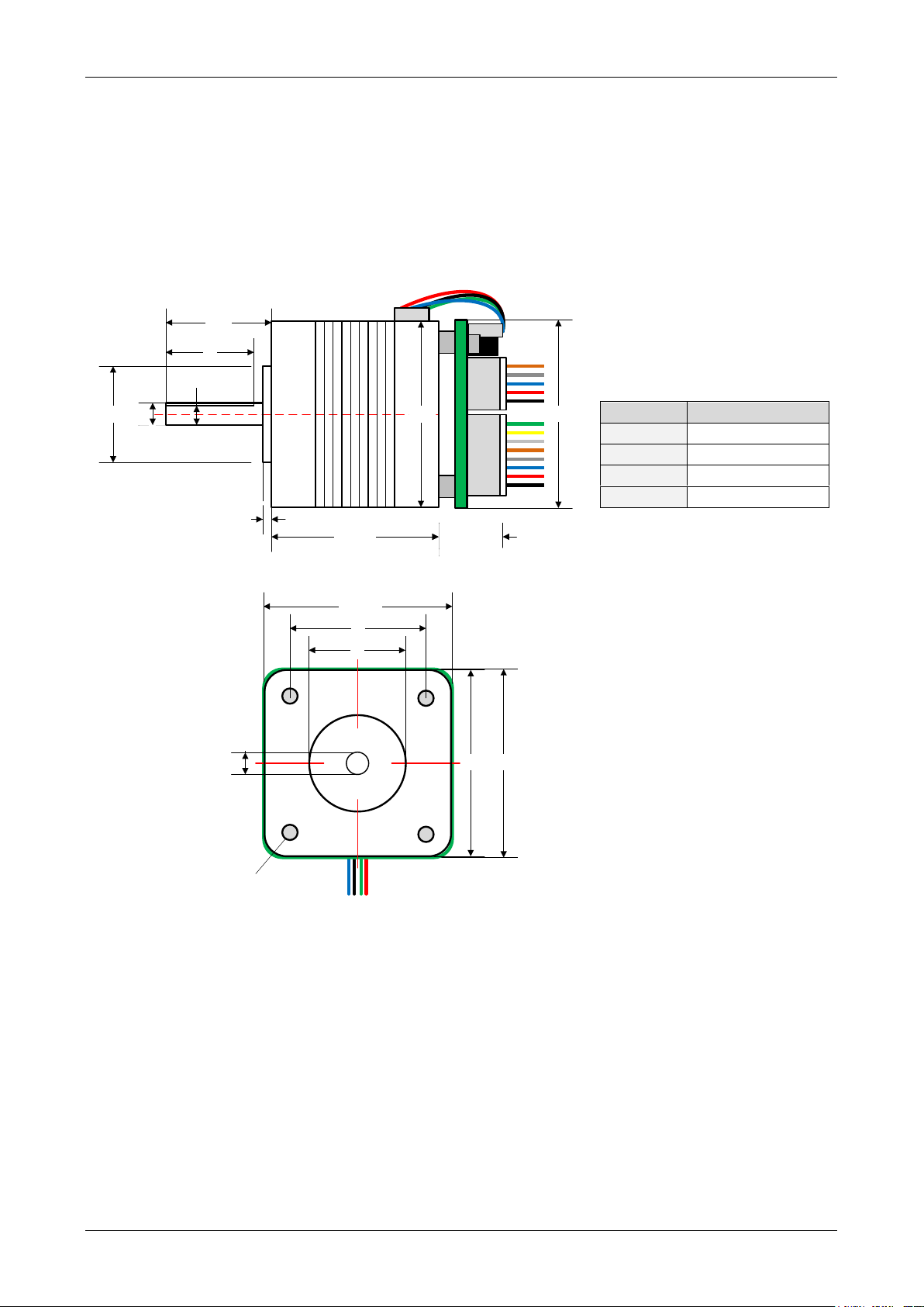
Length of motor
PD1
33.5±1mm
PD2
38±1mm
PD3
47±1mm
PD4
60±1mm
4 Mechanical and electrical interfacing
4.1 Size of PDx-140-42-SE
Currently, there is a choice between four 42mm bipolar stepper motors with different lengths and different
holding torques.
Figure 4.1: Dimensions PDx-140-42-SE (all values in mm)
Copyright © 2010, TRINAMIC Motion Control GmbH & Co. KG
Page 7

PDx-140-42-SE / TMCM-140-42-SE Manual (V1.05 / 2010-SEP-29) 7
Specifications
Parameter
Units
QSH4218
-34-20-022
-38-20-036
-47-20-044
-60-20-070
Step angle
˚ 1.8
1.8
1.8
1.8
Step angle accuracy
% +/-5
+/-5
+/-5
+/-5
Ambient temperature
°C
-20 … +50
-20 … +50
-20 … +50
-20 … +50
Max. motor temperature
°C
80
80
80
80
Shaft radial play (450g load)
mm
0.02
0.02
0.02
0.02
Shaft axial play (450g load)
mm
0.08
0.08
0.08
0.08
Max radial force
(20mm from front flange)
N
28
28
28
28
Max axial force
N 10
10
10
10
Rated voltage
V
RATED
V 2.0
2.4
2.4
4.4
Rated phase current
I
RMS RATED
A 2.0
2.0
2.0
2.0
Phase resistance at 20°C
R
COIL
Ω 1.0
1.2
1.4
2.3
Phase inductance (typ.)
mH
1.6
2.2
2.1
6.0
Holding torque
Nm
0.22
0.36
0.44
0.70
Insulation class
B B B
B
Rotor inertia
g cm2
35
57
68
102
Weight
kg
0.22
0.24
0.35
0.5
4.2 Size of electronics (TMCM-140-42-SE)
The electronic board has been designed in order to fit to a NEMA17 / 42mm size stepper motor with regard
to board size and mounting holes. Board size is 42mm x 42mm and there are two mounting holes (size:
3.2mm) for M3 screws.
Figure 4.2: Dimensions TMCM-140-42-SE (all values in mm)
4.3 Motor
Main characteristics of the four different motors available as part of the PDx-140-42-SE:
Table 4.1: Technical motor data
Copyright © 2010, TRINAMIC Motion Control GmbH & Co. KG
Page 8

PDx-140-42-SE / TMCM-140-42-SE Manual (V1.05 / 2010-SEP-29) 8
Power and serial
communication connector
Status LED
Motor connector
1
5
1
8
1 4
USB connector (mini USB)
I/O connector
1
5
Pin
RS232
RS485
CAN
Description
1
GND
GND
GND
Power and signal ground
2
VDD
VDD
VDD
Supply voltage (+24V DC nom.)
3
GND
GND
GND
Power and signal ground
4
RS232_TxD
RS485A
CAN_L
5 RS232_RxD
RS485B
CAN_H
open: no termination resistor
closed: 120 Ohm termination resistor
4.4 Connectors
The PDx-140-42-SE / TMCM-140-42-SE offers four connectors, a 5-pin power and serial communication
interface connector, an 8-pin input/output connector, a 4-pin motor connector (with PDx-140-42-SE already
connected to the attached motor) and a 5-pin mini-USB connector.
Figure 4.3: PDx-140-42-SE Connectors
4.4.1 Power and serial communication connector
A 5-pin JST PH series connector is used for power supply and serial communication. Three different
communication interface standards are available with this unit (as options): RS232, RS485 and CAN.
Table 4.2: Connector for power and communication
Mating connector from JST: PHR-5 (housing) and SPH-002T-P0.5S (crimp contact for AWG #30 to 24 / 0.05mm2
to 0.22mm2 wires).
For RS485 and CAN interface option the module contains a 120Ohm termination resistor:
For early versions of the unit a zero Ohm resistor is already assembled in order to activate the 120 Ohm line
termination on-board. This has to be removed in case the unit is not connected as last / first node in a
network or there is already proper bus termination installed!
Copyright © 2010, TRINAMIC Motion Control GmbH & Co. KG
Page 9

PDx-140-42-SE / TMCM-140-42-SE Manual (V1.05 / 2010-SEP-29) 9
Interface
Description
RS232
Short RxD and TxD for resetting the module.
RS485
- Demount the board from the motor.
- Short the two pins which are marked on the
figure below. The pins are on the back of the
board.
- Turn power ON and wait. The LED flashes quickly
now.
- Turn power OFF. The module is reset to factory
defaults now.
CAN
- Demount the board from the motor.
- Short the two pins which are marked on the
figure below. The pins are on the back of the
board.
- Turn power ON and wait. The LED flashes quickly
now.
- Turn power OFF. The module is reset to factory
defaults now.
4.4.1.1 Reset the module to factory defaults
Table 4.3: Reset the module to factory defaults
Figure 4.4: Pins for resetting the module
Copyright © 2010, TRINAMIC Motion Control GmbH & Co. KG
Page 10

PDx-140-42-SE / TMCM-140-42-SE Manual (V1.05 / 2010-SEP-29) 10
1
8
Pin
Label
Direction
Description
1
STOP_L
Input
Left stop switch input
(+5V compatible)
2
STOP_R
Input
Right stop switch input
(+5V compatible)
3
GND
Power
(GND)
Power and signal ground
4
VDD
Power
Supply voltage +24V DC nom.
5
OUT_0
Output
General purpose output (open collector)
6
OUT_1
Output
General purpose output (open collector)
7
IN_0
Input
General purpose input
(+5V and +24V compatible)
8
IN_1
Input
General purpose input
(+5V and +24V compatible)
1
4
Pin
Label
Direction
Description
1
OA1
Output
2-phase stepper motor phase A
2
OA2
Output
2-phase stepper motor phase A
3
OB1
Output
2-phase stepper motor phase B
4
OB2
Output
2-phase stepper motor phase B
1
5
Pin
Label
Description
1
VBUS
+5V power
2
D-
Data –
3
D+
Data +
4
ID
Not connected
5
GND
Ground
4.4.2 I/O connector
An 8-pin JST PH series connector is used for input/output signals.
Table 4.4: Connector for power and I/O
Mating connector from JST: PHR-8 (housing) and SPH-002T-P0.5S (crimp contact for AWG #30 to 24 / 0.05mm2
to 0.22mm2 wires).
4.4.3 Motor connector
A 4-pin JST PH series connector is used for connecting the motor.
Table 4.5: Connector for motor
Mating connector from JST: PHR-4 (housing) and SPH-002T-P0.5S (crimp contact for AWG #30 to 24 / 0.05mm2
to 0.22mm2 wires).
4.4.4 USB connector
A 5-pin mini-USB connector is available on board.
Table 4.6: Connector for USB
Copyright © 2010, TRINAMIC Motion Control GmbH & Co. KG
Page 11

PDx-140-42-SE / TMCM-140-42-SE Manual (V1.05 / 2010-SEP-29) 11
STOP_L
1k
10k
+5V
1nF
GND
STOP_R
1k
10k
+5V
1nF
GND
IN_0
10k
4k75
GND
+3V3
GND
IN_1
10k
4k75
GND
+3V3
GND
4.5 Input/output circuits
The module offers 2 stop switch inputs, 2 general purpose inputs and 2 general purpose outputs. The stop
switch inputs STOP_L and STOP_R are +5V tolerant and include 1k pull-up resistors to +5V. The general
purpose inputs IN_0 and IN_1 accept digital (e.g. 5V or 24V compatible) signals or analog signals (0..10V) and
include pull-down resistors.
The general purpose outputs are open-collector outputs with integrated freewheeling diodes. Max. sink
current per output is 100mA and max. voltage at output when output is inactive / output transistor is
switched off is limited to module supply voltage due to the integrated freewheeling diode.
4.5.1 Reference switch inputs
There are 2 reference/stop switch inputs (STOPL / STOPR). Both inputs offer an internal pull-up resistor (1k)
and accept voltages between 0 and +5V.
Figure 4.5: Reference/stop switch inputs STOP_L, STOP_R
4.5.2 General purpose inputs
There are 2 general purpose inputs (IN_0 / IN_1). Both inputs offer internal voltage divider and voltage
limiter and accept input voltages between 0 and +24V as digital inputs and between 0 and +10V as analog
inputs (depending on software settings). The voltage divider resistors act as pull-down resistors, also.
Early version of module (with pcb version 1.0 and 1.1) contained 1k resistor instead of 4k75 resistor as low
side resistor in voltage divider. For these modules full scale analog input range is +36V instead of +10V.
Copyright © 2010, TRINAMIC Motion Control GmbH & Co. KG
Figure 4.6: General purpose inputs IN_o, IN_1
Page 12

PDx-140-42-SE / TMCM-140-42-SE Manual (V1.05 / 2010-SEP-29) 12
1k
GND
VDD
OUT_0
BC847
1k
GND
VDD
OUT_1
BC847
4.5.3 General purpose outputs
There are 2 general purpose outputs (OUT_0 / OUT_1). Both outputs are open collector outputs and can drive
loads up-to 100mA. Especially for inductive loads a freewheeling diode to supply voltage (VDD) has been
included. This is also the reason why the external voltage at the general purpose outputs - when the
outputs are switched off - should not be higher than the supply voltage of the module + approx. 0.5V.
Figure 4.7: General purpose outputs OUT_0, OUT_1
Copyright © 2010, TRINAMIC Motion Control GmbH & Co. KG
Page 13

PDx-140-42-SE / TMCM-140-42-SE Manual (V1.05 / 2010-SEP-29) 13
5V Power Supply
USB
CAN
or
RS232
or
RS485
24V
PD-140-42-SE
progammable
Motion
Controller
with TMC428
High Power
Driver
TMC249
TMCL
Memory
sensOstepTM
Encoder
MOSFET
Driver
Stage
Step
Motor
5 Functional Description
The PANdrive PD-140-42-SE is a mechatronic solution including a 42 mm flange motor, a controller board
and a sensOstep™ encoder. It offers four motor torque options and can be controlled via CAN, RS232, RS485
or USB interface. Power supply, interface and general purpose I/Os can be connected with high density JST
connectors. The chopSync™ feature allows high speed movement avoiding resonances. The PD-140-42-SE
comes with the PC based software development environment TMCL-IDE for the Trinamic Motion Control
Language (TMCL™). Using predefined TMCL™ high level commands like „move to position“ or „constant
rotation“ a rapid and fast development of motion control applications is guaranteed. Communication traffic
is kept very low since all time critical operations, e.g. ramp calculation are performed on board. The TMCL™
program can be stored in the onboard EEPROM for stand-alone operation. In addition to TMCL™ CANopen is
available as firmware option, also.
Figure 5.1: Main parts of the PDx-140-42-SE
Copyright © 2010, TRINAMIC Motion Control GmbH & Co. KG
Page 14

PDx-140-42-SE / TMCM-140-42-SE Manual (V1.05 / 2010-SEP-29) 14
6 Firmware
Currently, there are two different firmware versions available for this unit – TMCL™ and CANopen. TMCL™ is
available for all interface options and is supplied as default firmware. Please refer to the TMCL™ firmware
manual for this unit for more details [TMCL].
With the CAN interface option also CANopen is available as firmware. This firmware supports the CiA 301
and CiA 402 profiles with support for homing mode, profile position mode and velocity mode. For more
details please refer to the CANopen manual [CANopen].
Copyright © 2010, TRINAMIC Motion Control GmbH & Co. KG
Page 15

PDx-140-42-SE / TMCM-140-42-SE Manual (V1.05 / 2010-SEP-29) 15
7 Torque curves
The following torque curves have been measured using the PANdrive PDx-140-42-SE with all four stepper
motors available as part of this unit. The four different stepper motors all offer the same max. coil current
but, differ with respect to holding torque, motor length, coil resistance and inductivity – to name a few. As
rule of thumb, more holding torque means more copper, longer motor, more coil resistance and higher
inductivity which limits the max. reachable velocity at the same supply voltage. All measurements were
taken at +24V driver supply voltage and max. motor current.
The figures below include torque curves for microstep operation and full step operation. With full step
mode it is possible to reach higher velocities whereas resonances normally prevent any smooth operation at
lower speeds (see torque curves below). Therefore, TMCL™ firmware offers programmable automatic switch
over between microstep operation at lower speeds and full-step operation at higher speed in order to take
advantage of both modes (please see TMCL™ firmware manual, axis parameter 211).
7.1 PD1-140-42-SE
The PD1-140-42-SE is the most compact version of this PANdrive series with the shortest stepper motor.
Figure 7.1: PD1-140-42-SE torque curve
Copyright © 2010, TRINAMIC Motion Control GmbH & Co. KG
Page 16

PDx-140-42-SE / TMCM-140-42-SE Manual (V1.05 / 2010-SEP-29) 16
7.2 PD2-140-42-SE
For applications where more torque is required than available with the PD1-140-42-SE, the PD2-140-42-SE
might be an option.
Figure 7.2: PD2-140-42-SE torque curve
7.3 PD3-140-42-SE
For applications where more torque is required than available with the PD2-140-42-SE, the PD3-140-42-SE
might be an option.
Figure 7.3: PD3-140-42-SE torque curve
Copyright © 2010, TRINAMIC Motion Control GmbH & Co. KG
Page 17

PDx-140-42-SE / TMCM-140-42-SE Manual (V1.05 / 2010-SEP-29) 17
7.4 PD4-140-42-SE
For applications where more torque is required than available with the PD3-140-42-SE, the PD4-140-42-SE
might be an option. The PD4-140-42-SE is the version with highest holding torque and the longest stepper
motor available for this PANdrive series.
Figure 7.4: PD4-140-42-SE torque curve
Copyright © 2010, TRINAMIC Motion Control GmbH & Co. KG
Page 18

PDx-140-42-SE / TMCM-140-42-SE Manual (V1.05 / 2010-SEP-29) 18
Symbol
Parameter
Min
Typ
Max
Unit
Vcc
+24 DC input
7
24
28.5
V
I
COIL_peak
Motor coil current for sine wave peak (chopper
regulated, adjustable via software)
0
2.8 *)
A
I
COIL_RMS
Continuous motor current (RMS)
0 2 *)
A
I
SUPPLY
Power supply current
<< I
COIL
1.4 * I
COIL
A
T
ENV
Environment temperature at max. current, 100%
duty cycle
(no forced cooling required)
+40 **)
°C
8 Operational ratings
The operational ratings shown below should be used as design values. In no case should the maximum
values been exceeded during operation.
Table 8.1: General operational ratings of the module
*) Please note: only PDx-140-42-SE and TMCM-140-42-SE with pcb version 1.1 or newer support specified max.
current over full temperature range. Older / pre-series versions may be limited with regard to temperature
range and / or max. motor current.
**) Test set-up / procedure: PANdrive PD4-140-42-SE mounted to a metal base plate in order to keep stepper
motor temperature within limits for the motor during test (table 4.1) / test inside climate chamber with
approx. 53l volume / no forced air convection during test / test duration at least 30min.
Please note: motor temperature should always be kept below upper limit for the motor - that is, motor /
PANdrive should be mounted to an appropriate metal / cooling plate or frame. Especially, the longest
available stepper motor which is part of the PD4-140-42-SE may easily reach 100°C or above when operated
at full current over long time without being mounted to any heat-conducting structure or forced air
convection. In case the TMCM-140-42-SE electronic module is mounted close to the motor as with the
PANdrives, the motor might substantially heat up the electronics and limit the maximum environmental
temperature during operation. The unit may be operated at higher environmental temperatures than
specified when the duty cycle of the motor and / or the motor current is reduced or in case the TMCM-14042-SE electronic module is mounted separately from the motor.
Copyright © 2010, TRINAMIC Motion Control GmbH & Co. KG
Page 19

PDx-140-42-SE / TMCM-140-42-SE Manual (V1.05 / 2010-SEP-29) 19
Symbol
Parameter
Min
Typ
Max
Unit
V
STOP_L/R_L
Low level input voltage for STOP_L/R switch
inputs
0.9
V
V
STOP_L/R_H
High level input voltage for STOP_L/R switch
inputs
1.9 5
V
V
IN_1/2_L
Low level input voltage for general purpose
inputs IN_1/2 (when configured as digital inputs)
1.6
V
V
IN_1/2_H
High level input voltage for general purpose
inputs IN_1/2 (when configured as digital inputs)
4.0 24
V
V
IN_1/2_ANA
Analog voltage full scale input range for general
purpose inputs IN_1/2 (when configured as
analog inputs)
0 10*)
V
V
OUT_1/2
Maximum voltage at general purpose outputs
(open collector output switched off)
VDD + 0.5
**)
V
I
OUT_1/2
Maximum output sink current for general purpose
outputs (open collector)
10
100
mA
Table 8.2: Operational ratings of input and output signals
*) Analog voltage full scale input range is +36V for early version of module
**) limited to module supply voltage + 0.5V due to integrated freewheeling diode between general purpose
output and module supply voltage
Copyright © 2010, TRINAMIC Motion Control GmbH & Co. KG
Page 20

PDx-140-42-SE / TMCM-140-42-SE Manual (V1.05 / 2010-SEP-29) 20
Signal
Description
Range
f
CLK
clock-frequency
0… 16 MHz
velocity
-
0… 2047
a_max
maximum acceleration
0… 2047
pulse_div
divider for the velocity. The higher the value is, the less
is the maximum velocity
default value = 0
0… 13
ramp_div
divider for the acceleration. The higher the value is, the
less is the maximum acceleration
default value = 0
0… 13
Usrs
microstep-resolution (microsteps per fullstep = 2
usrs
)
0… 7 (a value of 7 is
internally mapped to
6 by the TMC428)
3220482
velocity]Hz[f
]Hz[usf
div_pulse
CLK
usrs
2
]Hz[usf
]Hz[fsf
29div_rampdiv_pulse
max
2
CLK
2
af
a
usrs
2
a
af
9 PD-140 operational description
9.1 Calculation: Velocity and acceleration vs. microstep and
fullstep frequency
The values of the parameters sent to the TMC428 do not have typical motor values like rotations per second
as velocity. But these values can be calculated from the TMC428-parameters as shown in this document.
The parameters for the TMC428 are:
Table 9.1: TMC428 velocity parameters
The microstep-frequency of the stepper motor is calculated with
with usf: microstep-frequency
To calculate the fullstep-frequency from the microstep-frequency, the microstep-frequency must be divided
by the number of microsteps per fullstep.
with fsf: fullstep-frequency
The change in the pulse rate per time unit (pulse frequency change per second – the acceleration a) is
given by
This results in acceleration in fullsteps of:
with af: acceleration in fullsteps
Copyright © 2010, TRINAMIC Motion Control GmbH & Co. KG
Page 21
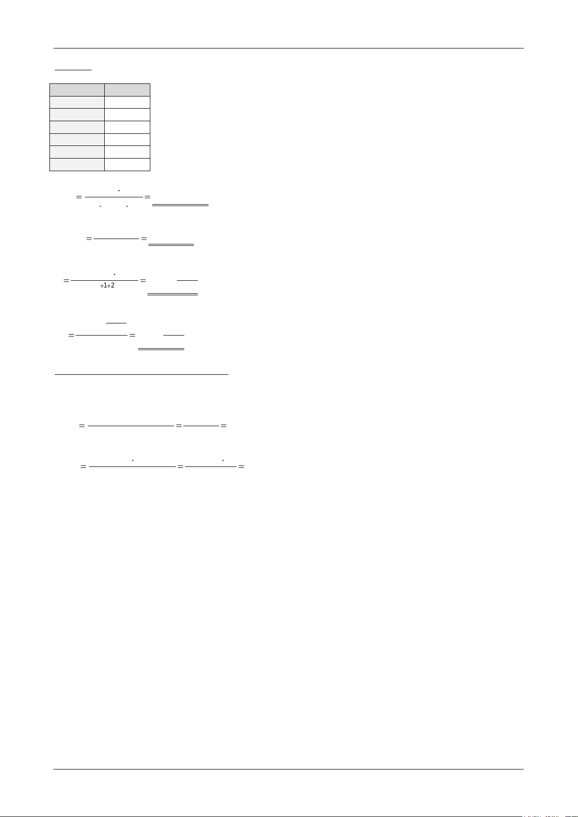
PDx-140-42-SE / TMCM-140-42-SE Manual (V1.05 / 2010-SEP-29) 21
Signal
value
f_CLK
16 MHz
velocity
1000
a_max
1000
pulse_div
1
ramp_div
1
usrs
6
Hz31.122070
3220482
1000MHz16
msf
1
Hz34.1907
2
31.122070
]Hz[fsf
6
s
MHz
21.119
2
1000)Mhz16(
a
2911
2
s
MHz
863.1
2
s
MHz
21.119
af
6
49.26
72
34.1907
rotationperfullsteps
fsf
RPS
46.1589
72
6034.1907
rotationperfullsteps
60fsf
RPM
Example:
Calculation of the number of rotations:
A stepper motor has e.g. 72 fullsteps per rotation.
Copyright © 2010, TRINAMIC Motion Control GmbH & Co. KG
Page 22

PDx-140-42-SE / TMCM-140-42-SE Manual (V1.05 / 2010-SEP-29) 22
Version
Date
Author
Description
1.00
2008-07-23
GE
Initial version
1.01
2008-09-01
GE
Ordering codes added
1.02
2008-10-28
GE
CAN connector pin assignment corrected
1.03
2008-12-17
SD
Size of the unit and functional description added
1.04
2009-10-21
GE
New hardware version + torque curves added
1.05
2010-09-29
SD
Paragraph Reset the module to factory defaults added.
Version
Date
Description
1.00
2008-04-27
First version, reduced motor current
1.10
2009-06-29
Second version, full production (series) version
1.20
2009-12-09
Several minor improvements
10 Revision history
10.1 Document revision
Table 10.1: Document revision
10.2 Hardware revision
Table 10.2: Hardware revision
Copyright © 2010, TRINAMIC Motion Control GmbH & Co. KG
Page 23

PDx-140-42-SE / TMCM-140-42-SE Manual (V1.05 / 2010-SEP-29) 23
11 References
[TMCL] PD-140 TMCL™ Firmware Manual (see http://www.trinamic.com)
[CANopen] CANopen Manual (see http://www.trinamic.com)
Copyright © 2010, TRINAMIC Motion Control GmbH & Co. KG
 Loading...