

Page 1

USER GUIDE
Trimble TX5
3D Laser Scanner
Version 2.00
Revision A
March 2013
1
Page 2

Corporate Office
Trimble Navigation Limited
935 StewartDrive
Sunnyvale, CA 94085
USA
www.trimble.com
Oil, Gas & Chemical
Trimble Navigation Limited
5475 KellenburgerRoad
Dayton,Ohio 45424
USA
Legal Notices
© 2012-2013, TrimbleNavigationLimited. Allrights reserved.
Trimble and the Globe & Trianglelogo are trademarks of Trimble
NavigationLimited,registered in the UnitedStates and inother
countries.
Microsoft,Excel,InternetExplorer,VisualStudio,Windows and Windows
XP are eitherregistered trademarks or trademarks ofMicrosoft
Corporation in the UnitedStates and/orothercountries.
All othertrademarks arethe property of theirrespective owners.
For implementationnotesforthird-party software,see Appendix A:
Implementation Notes, page 119.
For implementationnotesforthird-party software,refertothe Trimble
TX5 SC ENE Software LT User Guide.
Release Notice
This is the March 2013 release (Revision A) ofthe TrimbleTX5 3DLaser
Scanner User Guide.
Notices
For FCCcomplianceinformation,see Appendix B: FCC Compliance,
page 126.
For the assessment of risk ofocular injury from using the laserscanner,
refertothe expertopinionprovidedat the end of this guide.
Product Li mited Warranty Information
For applicable productLimited Warranty information,refer to the
warranty informationprovided at the end ofthis guide.
End User License Agreement
For details of the software EULA, refer to the EULA provided at the end
of this guide.
For details of the software EULA, refer to the Trimble TX5 SCENE
Software LT User Guide.
2 Trimble TX5 3D Laser Scanner User Guide
Page 3

Contents
1 Introduction 6
The Trimble TX5 3D laser scanner 7
How the laser scanner works 8
Equipment 10
Recommended optional equipment 11
2 Safety Precautions and Maintenance 12
Generalsafety information 13
Electricalsafety 14
PowerBlock battery safety 15
PowerDock battery charger safety 16
Laser safety 17
Mechanical security 22
Transport 22
Storage 22
Maintenance 23
General 23
Cleaning instructions for optics 23
3 Parts and their Functions 26
Scanner – right side 27
Scanner – left side 28
Scanner – front 29
Scanner – bottom 30
PowerDock battery charger cradle 31
Normal LEDbehavior 32
LEDbehavior in case of errors 32
4 Getting Started 33
Charging the battery 34
Charging the battery in the laser scanner 34
Tips for using the battery 34
Charging the battery with the PowerDock battery charger 34
Setting up the tripod 36
Mounting the laser scanner 37
Using an SD memory card 38
Preparing an SDmemory card 38
Inserting the SD memory card 39
Ejecting the SD memory card 39
Powering the laser scanner 39
Supplying power with the battery 39
Trimble TX5 3D Laser Scanner User Guide 3
Page 4

Contents
Supplying power with the external power supply unit 40
Powering on the laser scanner 42
Initial scanner settings 43
Setting the interface language 44
Setting the date and time 44
Setting the date format 45
Changing the date and time 45
Setting the unit of length and the temperature scale 46
Entering scanner information 47
Scanning 48
Setting the scan parameters 49
Scanning parameters overview 60
Enhancing the scanning environment with artificial targets 62
Environmental conditions 64
Starting a scan 65
Shutting down the laser scanner 67
Powering off the laser scanner 68
Removing the battery 68
Unplugging the power supply 68
5 TX5 Controller Software 69
Generalelements 70
Status bar 70
Navigation bar 71
Frequently used buttons 71
Onscreen keyboard 73
Home screen 74
Manage screen 75
Managing scan projects 76
Managing scan profiles 80
Factory predefined scan profiles 82
Managing operators 83
Generalsettings 86
Service 93
Sensors 100
View scans 105
Online help 108
6 Troubleshooting and Servicing 109
Available replacement parts 110
Scanner LED behavior 111
File structure of the SD memory card 112
Error messages 113
Trimble TX5 3D Laser Scanner User Guide 4
Page 5

Contents
Mount dimensions 115
Laser scanner dimensions 116
Laser scanner power socket 117
Technicalsupport 118
Appendix A: Implementation Notes 119
Appendix B: FCC Compliance 126
Trimble TX5 3D Laser Scanner User Guide 5
Page 6

In this chapter:
n
The Trimble TX5 3D laser scanner
n
How the laser scanner works
n
Equipment
C H A P T E R
1
1Introduction
Trimble TX5 3D Laser Scanner User Guide 6
Page 7
1 Introduction
The Trimble TX5 3D laser scanner
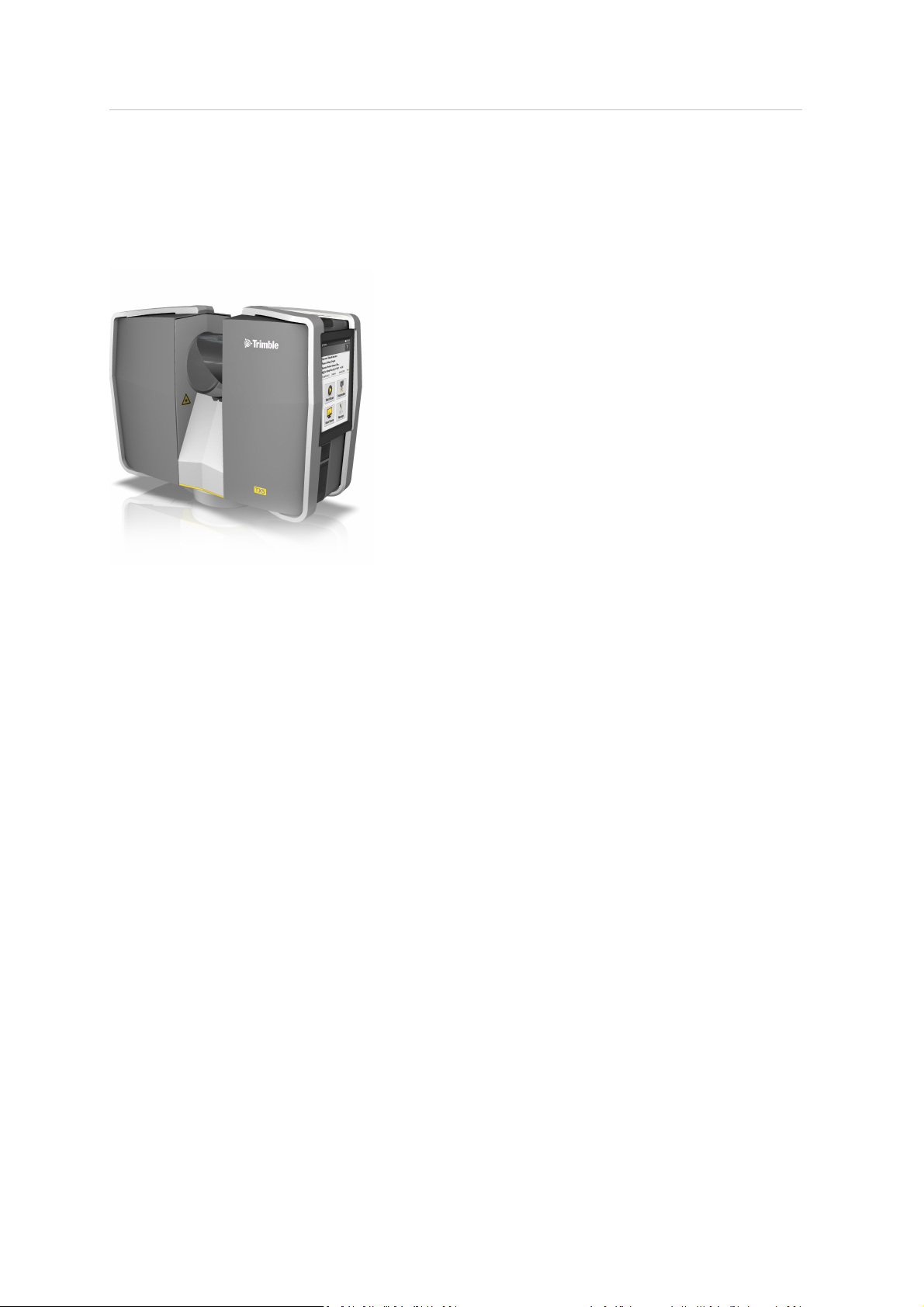
The Trimble®TX5 3D laserscanner is a high-speed three-dimensional laser scanner for detailed
measurement and documentation. The laser scanner uses laser technology to produce exceedingly
detailed three-dimensional images of complexenvironments and geometries in only a few minutes.
The resulting images are an assembly of millions of 3D measurement points.
The main features are:
l
High accuracy.
l
High resolution.
l
High speed.
l
Intuitive control via the built in touchscreen display.
l
High mobility due to its small size, light weight, and the integrated quick charge battery.
l
Photorealistic 3D color scans due to the integrated color camera.
l
Integrated dual axis compensator to automatically levelthe captured scan data.
l
Integrated compass and altimeter to give the scans an orientation and a height information.
l
WLANto remotely control the scanner.
Trimble TX5 3D Laser Scanner User Guide 7
Page 8
1 Introduction
How the laser scanner works
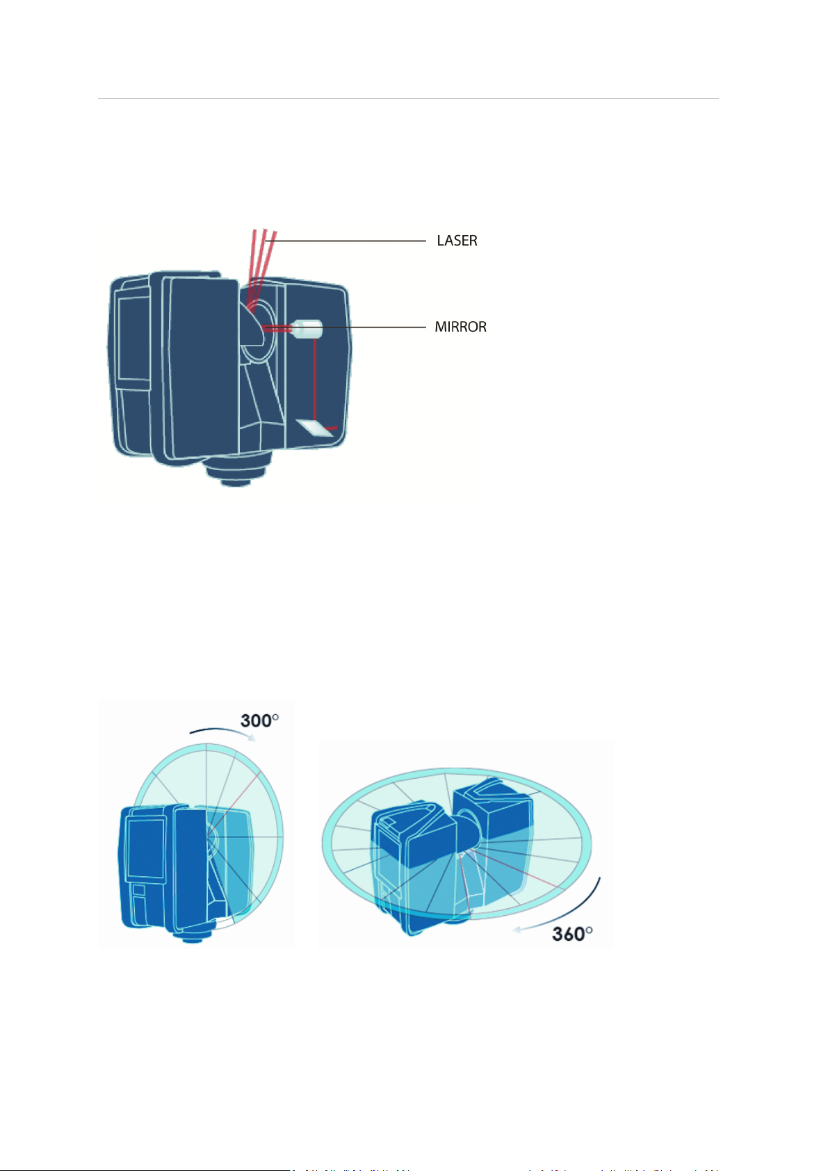
In principle, the TX5 3D laser scanner works by sending an infrared laser beam into the center of its
rotating mirror. The mirror deflects the laser beam on a vertical rotation around the environment
being scanned; scattered light from surrounding objects is then reflected back into the scanner.
To measure the distance, the laser scanner uses phase shift technology, where constant waves of
infrared light of varying length are projected outward from the scanner. Upon contact with an
object, they are reflected back to the scanner. The distance from the scanner to the object is
accurately determined by measuring the phase shifts in the waves of the infrared light.
HYPERMODULATION greatly enhances the signal-to-noise ratio of the modulated signal with the
help of a special modulation technology. The x, y, z coordinates of each point are then calculated by
using angle encoders to measure the mirror rotation and the horizontal rotation of the laser
scanner. These angles are encoded simultaneously with the distance measurement. Distance,
vertical angle and horizontal angle make up a polar coordinate (δ, α, β), which is then transformed
to a Cartesian coordinate (x, y, z). The scanner covers a 360° x 300° field of view.
Trimble TX5 3D Laser Scanner User Guide 8
Page 9

1 Introduction
Additionally, the laser scanner determines the reflectivity of the captured surfaces by measuring the
intensity of the received laser beam. In general, bright surfaces reflect a greater portion of the
emitted light than do dark surfaces. This reflectivity value is used to assign a corresponding grey
value to each single point.
The single point measurements are repeated up to 976,000 times per second. The result is a point
cloud, a three-dimensional dataset of the scanner's environment (hereinafter referred to as the
"laser scan" or "scan"). Depending on the selected resolution (points acquired per rotation) each
point cloud consists of millions of scan points.
The laser scans are recorded to the removable SD memory card, enabling easy and secure transfer
to Trimble TX5 SCENE software.
For a list of the potentialfields of application of the TX5 3D laser scanner, go to www.trimble.com.
This manual provides an introduction to the TX5 3D laser scanner. At a minimum, read Safety
Precautions and Maintenance (page 12)and Getting Started (page 33) beforefirst use.
Trimble TX5 3D Laser Scanner User Guide 9
Page 10
1 Introduction
Equipment
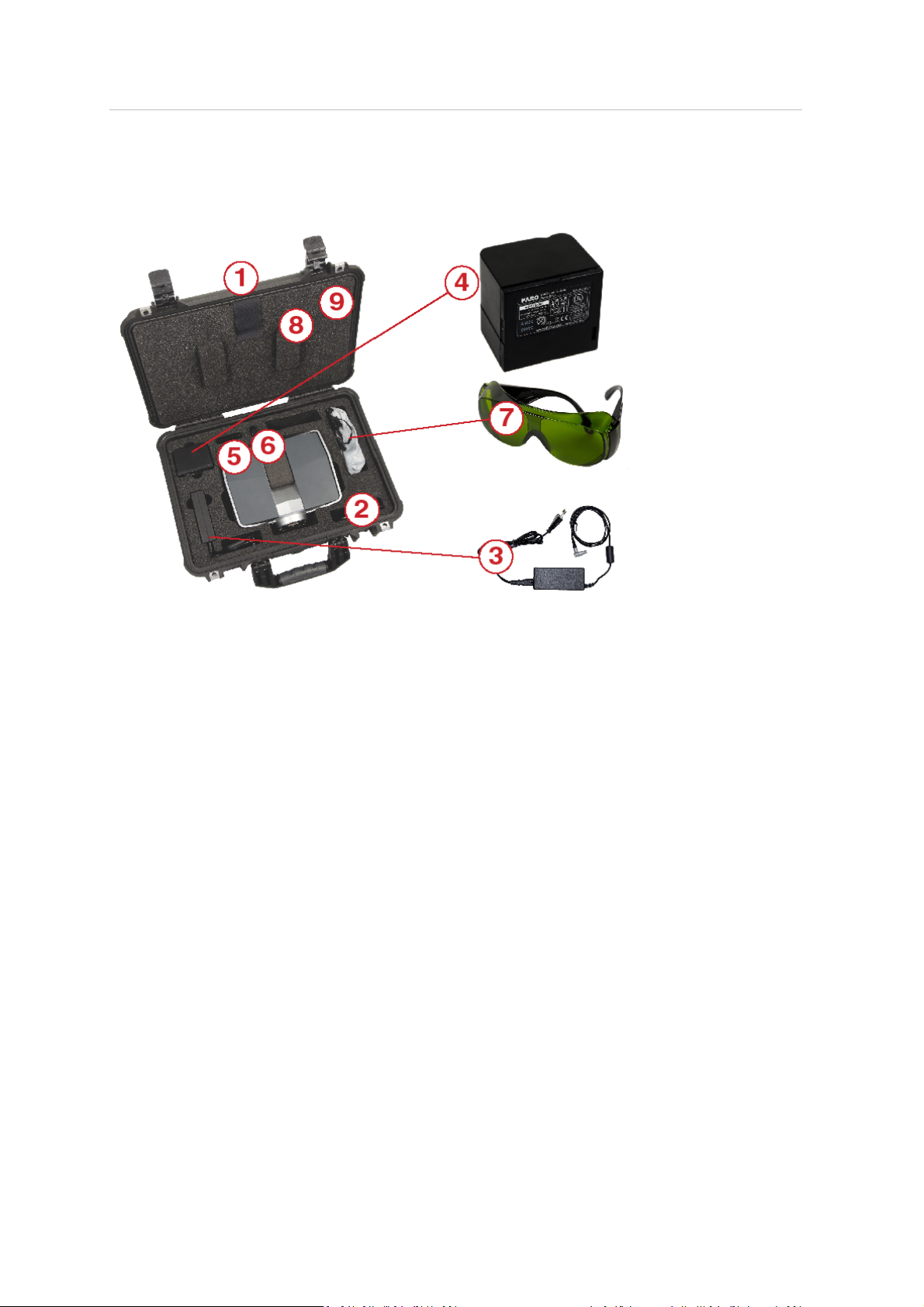
The TX5 3D laser scanner is shipped with the following equipment:
Scanner transport and carry case
❶
AC power cable
❷
Externalpowersupply unit with cable
❸
PowerBlock battery
❹
Memory card case
❺
USB memory card reader
❻
Laser safety goggles
❼
Quick Start Guide, situated in the case lid
❽
CD with TX5 SCENEsoftwareand this user guide, located in the case lid
❾
In addition, an SDmemory card is located inside the scanner.
Trimble TX5 3D Laser Scanner User Guide 10
Page 11

1 Introduction
Recommended optional equipment
l
Tripod
l
Quick Release for convenient mounting of the laser scanner to the tripod
l
Spare battery
l
PowerDock charging cradle
Retain all packing materials as you may need them later.
The SD memory card, a charged PowerBlock battery or the external power supply unit with AC
power cable, and a tripod are the minimum required equipment you need to carry out a scanning
project.
Trimble TX5 3D Laser Scanner User Guide 11
Page 12

Maintenance
In this chapter:
n
Generalsafety information
n
Electricalsafety
n
Laser safety
n
Mechanical security
C H A P T E R
2
2Safety Precautions and
n
Transport
n
Storage
n
Maintenance
Trimble TX5 3D Laser Scanner User Guide 12
Page 13

2 Safety Precautions and Maintenance
General safety information
l
Read this User Guide carefully and referto it. Pay close attention to all warnings and followthe
instructions step by step.
CAUTION – Do not open the housing as this may damage the product, which will affect the product's warranty.
l
Servicing and repair must only be done by qualified service personnel authorized by Trimble.
l
Unplug this product from the power outlet, remove the battery and referservicing to qualified
service personnel under the following conditions:
ll
The power-supply cord or plug is damaged.
l
The product has been exposed to rain, water, or other liquids.
l
The product has been dropped or damaged in any way.
l
Objects have fallen onto the product.
l
The product does not operate normally by following the operating instructions.
l
The product exhibits a distinct change in performance.
l
The required service and calibration date is reached.
l
Only replacement parts authorized by Trimble may be used according to the instructions
obtained from Trimble. For a list of availablereplacement parts, see Available replacement
parts, page 110.
l
Do not expose the product to extreme temperatures. The ambient temperature should not be
loweror higher than given in the specifications. Do not use the laser scanner near heat sources
such as radiators, heat registers, or other products (including amplifiers) that produce heat.
l
Do not immerse the product into water. Liquid in the product's enclosure can lead to damage,
fire, or electricshocks.
l
Do not use the laser scanner in vicinity of strong magnetic or electricalfields.
l
For outdoor use, use the PowerBlock battery as the power supply and ensure that the device is
protected from rain or spray water. The scanner should be used in a non-condensing
environment.
l
When the product is transferred from a cold to a significantly warmer environment, water may
condense on some elements inside the scanner. To avoid this, we recommend placing the
scanner in an airtight plastic bag beforebringing it from a cold to a significantly warmer
environment. This allows the condensation to form on the bag and not inside the scanner. If
you do not have the possibility to pack the scanner airtight, wait until observable condensation
water evaporates from the scanner before switching on the laser scanner.
l
Properly dispose of the product and batteries in accordance to the national regulations. For
more information, see Notices, page 2.
Trimble TX5 3D Laser Scanner User Guide 13
Page 14

2 Safety Precautions and Maintenance
Electrical safety
WARNING – Do not open the housing. Dangerous high voltages are present inside the enclosure. Only qualified
service personnel should open the cabinet. Never push objects of any kind into this product through openings as
they may touch dangerous voltage points or cause short circuits. This could result in a fire, electric shock, and
damage to the product.
This product should be operated only from the powersource or the battery supplied or
recommended by Trimble. Please ensure that the specifications of the AC converter are met by your
line voltage. If you do not know the power line voltage in your area, please consult your local power
company.
To avoid electricalshock, use the power supply unit in dry indoor environments only.
Trimble TX5 3D Laser Scanner User Guide 14
Page 15

2 Safety Precautions and Maintenance
PowerBlock battery safety
The following safety measures must be followed when working with the PowerBlock battery:
l
Only use the charger recommended by Trimble to charge the battery.
l
Do not charge or discharge damaged batteries.
l
Do not charge the battery in the laser scanner when it is stored in the transport case.
l
Do not use wet or dirty batteries in the laser scanner or with the charger.
l
Charge within limits of 0°C (+32°F) and 45°C (113°F) temperature. Recommended charging
temperatures: 10°C (50°F) to 30°C (86°F).
l
Discharge within limits of -20°C (-4°F) and 60°C (140°F)temperature. Recommended operating
temperatures: 5°C (41°F) to 40°C (104°F).
l
Insert or remove batteries from the laser scanner in dry and dust-freeenvironments only.
l
When the laser scanner is not in use for a longer period of time, remove the battery.
l
Store the battery only when it is charged (at least 60% charge state). It is recommended to
charge the battery once a year when it is stored long-term.
l
Storage temperatures: -20°C (-4°F) to 45°C (113°F), storage humidity range: 0% to 80%. Store in
a wellventilated area. Do not store with metal objects. Short circuit can ransom burn.
l
Do not bring metal objects into contact with the batteries' terminals. The terminals may short
circuit and generate heat in this condition.
l
Do not immerse batteries into wateror fire(danger of explosion).
l
Dispose of batteries in accordance with environmental regulations. Contact your local waste
disposal management authority for guidelines concerning lithium ion batteries.
Trimble TX5 3D Laser Scanner User Guide 15
Page 16

2 Safety Precautions and Maintenance
PowerDock battery charger safety
Observe the following safety measures when working with the Trimble PowerDock battery charger.
The charger is available as an optional accessory:
l
Do not charge any batteries other than the Trimble PowerBlock batteries in the PowerDock
battery charger.
l
Regularly check plug, cord and the charger itself. In case of damage contact Trimble Support.
l
Do not bring metal objects into contact with the charger terminals. The terminals may short
circuit and generate heat in this condition.
l
To avoid electricalshock, use the charger and the power supply unit in dry indoor
environments only.
l
Do not operate the charger in an environment allowing exposure to moisture, combustible
fluids or gasses. Danger of explosion!
l
The charger should be kept in a dry room, out of the reach of children.
Trimble TX5 3D Laser Scanner User Guide 16
Page 17
2 Safety Precautions and Maintenance
Laser safety
The TX5 3D laser scanner produces an invisible laser beam with a wavelength of 905nm. The average
laser power maximum is 20mW and the beam divergence is typically 0.19mrad (0.011°).
In accordance to the standard IEC 60825-1:2007, Ed 2.0, the TX5 3D laser scanner is classified as a
Class 3R laser system. According to this standard, direct intrabeam viewing may be hazardous for
the eyes when working within an area around the Class 3R laser system where the defined exposure
limits are exceeded.
However, exceeding the exposure limits does not necessarily mean that an actual risk for injury
exists. An analysis comparing the exposure levels of the eye that can be produced by the TX5
3Dlaser scanner with injury thresholds for the retina in order to assess the risk for ocular injury
when exposure occurs, comes to the conclusion that "exposure of the eye under normal
conditions, as well as for reasonably foreseeable worst-case conditions, should not induce
ocular injury." For more information, refer to the expert opinion included at the end of this guide.
From a biophysical point of view, the TX5 3D laser scanner can thus be considered as eye safe and it
would not be necessary to wear eye protection.
However, depending on national regulation or work placesafety legislation, it might be necessary to
weareye protection and to observe other safety measures when the defined exposure limits are
exceeded and when exposure can occur. To enable the user to identify the laser hazard area
(nominal ocular hazard area – NOHA)around the scanner within which the defined exposure limits
are exceeded, the TX5 Controller softwareshows the actual valid eye safety distance (nominal ocular
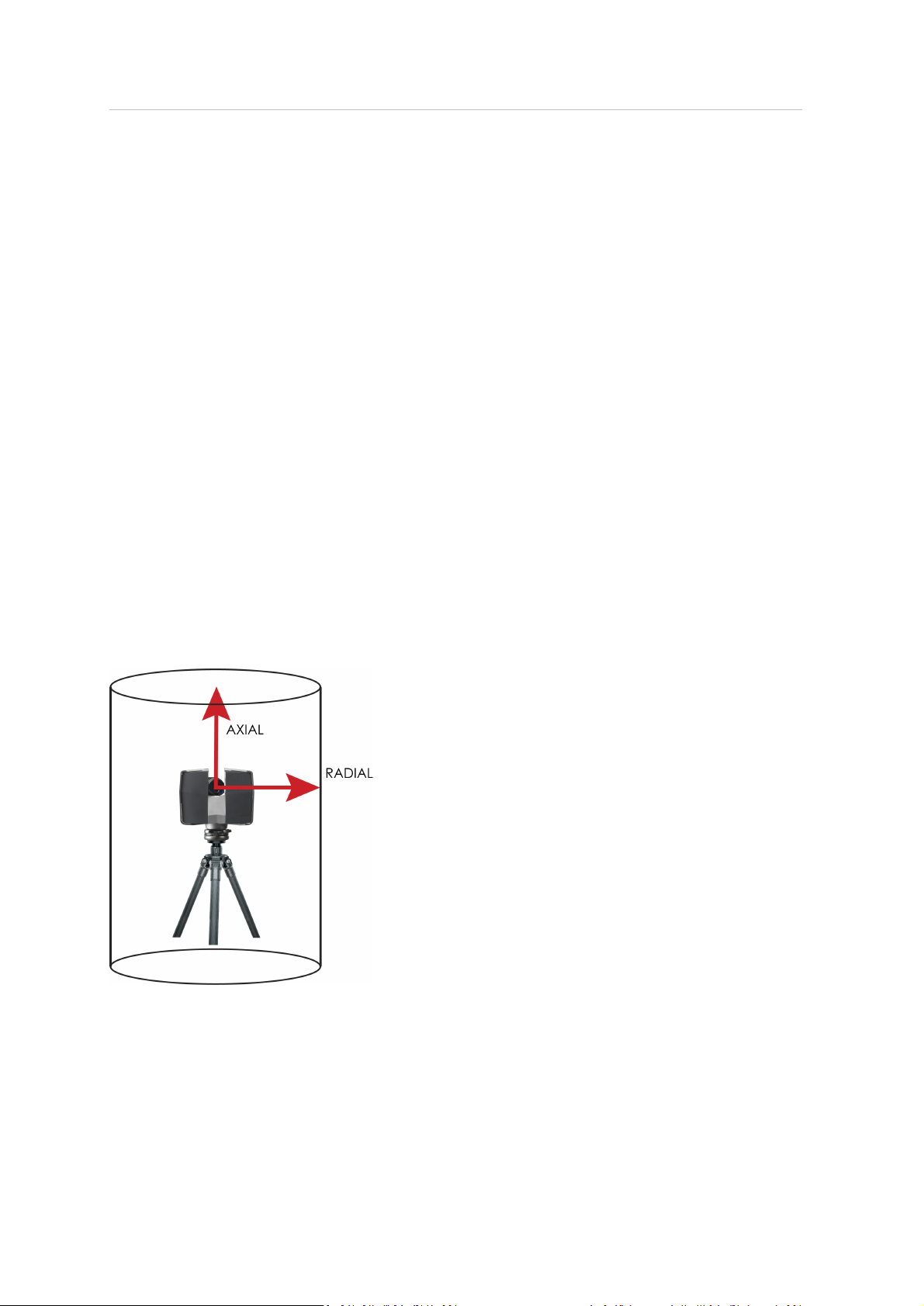
hazard distance – NOHD). We differentiatebetween the axial and the radial NOHD. The resulting
NOHA surrounding the scanner can thus be described as a cylinder along the scanner’s Z axis of
rotation, where the radial NOHD is equivalent to the cylinder’s radius and the axial NOHD is
equivalent to its center line coming from the center of the scanner mirror.
Both, the axial and the radial NOHD are dependent on the requested scanning resolution and
quality (see Setting the scan parameters, page 49). The table below contains the axial and radial
NOHD (in meters), repetition rate and pulse duration for all resolution and quality combinations
that are available.
Trimble TX5 3D Laser Scanner User Guide 17
Page 18

2 Safety Precautions and Maintenance
Resolution Quality Repetition rate
Mio. Pts (full scan) axial radial
(Hz)
Pulse duration (µs) NOHD (m)
710.7 1/1 1x 24 13.081 7.50 3.60
710.7 1/1 2x 12 15.026 12.50 6.30
710.7 1/1 3x 6 17.268 20.30 10.90
710.7 1/1 4x 3 23.155 29.40 16.20
177.7 1/2 1x 48 13.081 4.50 1.80
177.7 1/2 2x 24 15.026 7.50 3.20
177.7 1/2 3x 12 17.260 12.50 5.50
177.7 1/2 4x 6 22.689 20.30 8.30
177.7 1/2 6x 3 23.155 29.40 16.20
44.4 1/4 1x 95 44.083 2.70 0.30
44.4 1/4 2x 48 15.026 4.50 1.60
44.4 1/4 3x 24 17.260 7.50 2.80
44.4 1/4 4x 12 22.686 12.50 4.20
44.4 1/4 6x 6 22.689 20.30 8.30
44.4 1/4 8x 3 23.155 29.40 16.20
28.4 1/5 2x 60 15.026 3.80 1.30
28.4 1/5 3x 30 17.260 6.30 2.20
28.4 1/5 4x 15 22.686
10.60
3.30
28.4 1/5 6x 7.5 22.689 20.30 8.30
11.1 1/8 2x 95 88.072 2.70 0.20
11.1 1/8 3x 48 17.260 4.50 1.40
11.1 1/8 4x 24 22.686 7.50 2.10
11.1 1/8 6x 12 22.686 12.50 4.20
11.1 1/8 8x 6 22.689 20.30 8.30
7.1 1/10 3x 60 186.912 3.80 0.70
7.1 1/10 4x 30 22.686 6.30 1.70
7.1 1/10 6x 15 22.686 10.60 3.30
7.1 1/10 8x 7.5 22.689 20.30 8.30
2.8 1/16 3x 95 116.820 2.70 0.10
2.8 1/16 4x 48 233.640 4.50 0.90
2.8 1/16 6x 24 22.686 7.50 2.10
2.8 1/16 8x 12 22.686 12.50 4.20
1.8 1/20 4x 60 186.912 3.80 0.40
1.8 1/20 6x 30 22.686 6.30 1.70
1.8 1/20 8x 15 22.686 10.60 3.30
0.7 1/32 4x 95 116.820 2.70 0.10
0.7 1/32 6x 48 233.640 4.50 0.90
0.7 1/32 8x 24 22.686 7.50 2.10
Trimble TX5 3D Laser Scanner User Guide 18
Page 19

2 Safety Precautions and Maintenance
When working with the laser scanner you should be aware of the following laser safety measures:
WARNING – This product employs a laser system. To prevent direct exposure to the laser beam, do not attempt
to open the enclosure.
WARNING – Use of controls or adjustments or performance of procedures other than those specified in this
manual may result in hazardous radiation exposure.
l
Avoid looking into the direction of the laser. Avoid direct eye exposure, do not stare into the
laser beam and do not direct it to other people.
l
Do not view the laser beam directly with optical instruments.
l
Do not place mirrors or objects with reflective surface into the beam. The mentioned safety
measures are also valid for the reflected laser beam.
l
The scanner should be operated by trained personnel only.
l
The customer should assess the proper functioning of the delivered laser scanner at regular
intervals. You should immediately stop further use of the laser scanner if any failure is found. It
should be regularly checked and certified by a Trimble serviceprovider. The serviceintervals
should not exceed a maximum period of one year. For more information, contact your Trimble
dealer.
l
Respect the safety precautions and control measures that are specified in IEC 60825-1:2007, Ed
2.0. Also respect differences to the mentioned safety precautions and control measures that
may exist in national or regional publications.
Depending on national regulation or work place safety (health and safety at the workplace)
legislation, further laser safety measures might be necessary, such as:
l
Personnel working in distances shorter than the NOHD must wear laser safety goggles.
l
Prevent people without laser safety goggles from entering the NOHA(for example, by using a
safety fence).
l
The NOHA should be posted with appropriate laser warning signs and should be demarcated.
l
Companies working with Class 3R laser systems have to appoint a laser safety officer.
Note – These mentioned laser safety measures raise no claim to completeness. Rrefer to your
national regulations and legislations for more information on required laser safety measures when
working with Class 3R laser systems.
If working with laser safety goggles, they must be selected for the specific type of laser. For the TX5
3D laser scanner , use goggles which are specified for DI 800-980 L5 or higher. D stands for
continuous wave laser mode, I for pulsed laser mode, 800-980describes the laser wavelength, and
L5 is the L-rating, which is used to indicatethe levelof protection provided for specific wavelength
ranges. Refer to your laser safety commissioner for more information.
Trimble TX5 3D Laser Scanner User Guide 19
Page 20
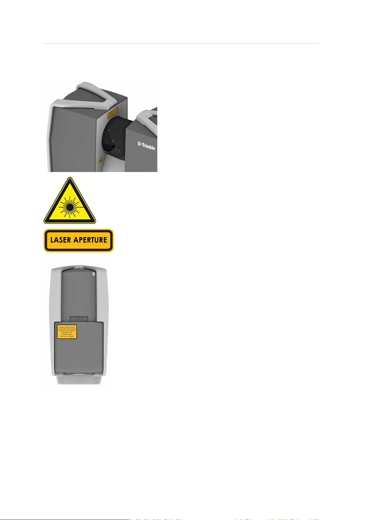
2 Safety Precautions and Maintenance
In accordance with IEC 60825-1:2007, Ed 2.0, the TX5 3Dlaser scanner is equipped with the following
laser signs:
Trimble TX5 3D Laser Scanner User Guide 20
Page 21

2 Safety Precautions and Maintenance
The TX5 3D laser scanner stays within the limits of laser class 1 if allinstructions of this manual are
obeyed, especially if no one is allowed to enter the NOHD without wearing laser safety goggles.
Trimble TX5 3D Laser Scanner User Guide 21
Page 22

2 Safety Precautions and Maintenance
Mechanical security
The laser scanner may only be used when set on a flat and stable surface. Severe injuries may result
if the laser scanner overturns. Only use equipment recommended by Trimble and follow the setup
instructions in this manual or in the manual of the manufacturer of the equipment.
If using a cart, move the setup with special care. Never move the cart by pulling at the power cables.
Pushing or pulling of the cart with too much force, sudden stops, or an uneven surface can cause an
upset of the laser scanner.
The laser scanner willrotate clockwise up to 360 degrees when performing a scan. Ensure that the
case of the laser scanner can rotate freely and will not hit any objects during the scan.
The mirror unit rotates with high speed whilescanning and for a short period after the scan. Do not
touch the rotating mirror unit with your hands or any objects at the risk of personal injury and
damage to the laser scanner.
Transport
When carrying the laser scanner, take care not to drop it. Strong impact may damage the laser
scanner and render it incapable of proper operation. Carry the laser scanner separately from its
equipment or – for best protection – use the original transport case.
When shipping and transporting the laser scanner by rail, sea, air, or in a road vehicle, make sure to
use its originaltransport case and a suitable outer cardboard box for best protection against shock
and vibration.
The PowerBlock batteries are Li-Ion batteries and are thus classified as "dangerous goods". When
transporting or shipping the PowerBlock batteries, ensure that you observe the applicable and
international rules and regulations. For further information, contact your local forwarderbefore
transportation or shipping.
For Li-Ion batteries with less than 100Wh energy content, an exemption is provided that allows you
to carry such a battery without further paperwork. The maximum Li-Ion battery energy a single
person may carry is 200Wh.
Note – Make sure that the total energy content of all Li-Ion batteries that you (as a single person)
carry is less than 200 Wh and that no single battery has more than 100 Wh energy content.
Note – The laser scanner must be turned off during transportation or shipping in a transport case.
Remove the battery from the laser scanner before shipping.
Storage
Prior to storing the laser scanner for a longer time, remove the battery. Pack the scanner and the
battery in its shipping case to protect it from environmental hazards, dust, and dirt. Store all
components in an environment where the humidity level is low, the temperature is relatively stable,
and where they will not be subject to extreme temperatures, environmental conditions, or heavy
vibrations.
Trimble TX5 3D Laser Scanner User Guide 22
Page 23

2 Safety Precautions and Maintenance
Maintenance
General
It is recommended that you check your laser scanner at least once a month. This enables you to
spot trouble before it starts and helps provide you with an efficient measuring system.
The laser scanner is a precision instrument that contains many sensitive components, and it must
be handled with care. Followthese procedures to prevent problems with your system:
l
Check the cables for damage to outside insulation, connectors, and pins.
l
Check the housing of the scanner for damage.
l
Check the housing and the connectors of the battery for damage.
l
Place a dust cover over the laser scanner when it is not in use.
l
Do not lubricate the laser scanner.
To ensure proper functioning of the laser scanner, it should be regularly checked and certified by a
Trimble serviceprovider. The serviceintervals should not exceed a maximum period of one year. For
more information, contact your Trimble dealer.
Cleaning instructions for optics
Note – To avoid unnecessary damage or wear, only clean the optics when the degree of
contamination has an impact on the scan quality (e.g. an increase in range noise or a decrease in
scan range) and requires cleaning for proper function.
Major contamination and improper handling to clean optics may impact the scanning quality. Selfcaused damages can result in a complete replacement of the part at the expense of the
customer.
l
We recommend using latex gloves. If you sufferfrom latex allergies use gloves that are suitable
for you. Lightly rub the gloves after taking them off with laboratory cloths and isopropanol to
remove grease and dirt.
l
Do not touch the opticalsurfaces with bare hands or laboratory gloves if at all possible.
l
Turn the scanner off before cleaning the optics.
Note – Before cleaning the mirror optics, cover the lens with a cap and avoid any contact with
the lens.
l
Only use cleaning fluid WITHOUT alcohol or acetone to clean the optics. We recommend
alcohol-free lens cleaner that can be found in most opticalsupply stores.
l
In the event acetone accidentally comes in contact with the mirror or lens, IMMEDIATELY rinse
with water(distilled, if possible).
Trimble TX5 3D Laser Scanner User Guide 23
Page 24
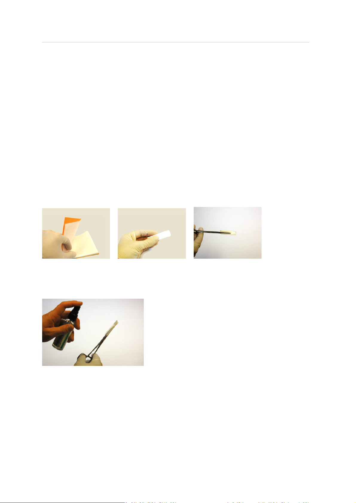
2 Safety Precautions and Maintenance
What's needed:
l
Compressed air spray (oil-free -opticalsupply store)
l
Alcohol free cleaning fluid in spray bottle / dropping bottle
l
1 Package lens tissue (optical supply store)
l
1 Package laboratory cloths (lint-free)
l
1 Pair of tweezers or forceps
l
1 Pair of non-powdered gloves
Additionally for a greatly contaminated mirror:
l
Mild neutral soap (optical supply store)
Slightly contaminated mirror
Handling lens tissue: Fold two or three pieces of lens tissue and clamp them in the tweezers or
forceps.
l
First, use a little compressed air spray (oil-free) to clean the surface of the optics.
l
Mist the clamped lens tissues with the cleaning fluid (do not soak). If necessary, wait a few
seconds until some of the solution has evaporated.
l
Bring the scanner mirror into position and hold it with one hand; do not touch the mirror
surface. Use the other hand to clean the mirror. Starting at the edge of the mirror, apply light
pressure and wipe across the mirror into one direction. Repeat until the mirror surface is clean.
Use a clean area of the lens tissue (fold used lens tissue accordingly) or new lens tissue for each
Trimble TX5 3D Laser Scanner User Guide 24
Page 25

2 Safety Precautions and Maintenance
wipe. Avoid touching the mirror surfacewith gloves. Do not touch the mirror surface and the
receiver lens with the tweezers or forceps.
Greatly contaminated mirror
Folding laboratory cloths: Take several individual laboratory cloths out of the package and fold
twice. Set onto an oil-freesurface.
l
Fold the laboratory cloth and soak the edge in the cleaning fluid. Carefully clean the edge of the
mirror.
l
Completely mist a fresh folded laboratory cloth with mild neutral soap along the edge.
l
Starting at the edge of the mirror, apply light pressure and wipe across the mirror. Repeat
multiple times in linear direction.
l
Then clean with appropriate cleaning fluid. See Cleaning instructions for optics, page 23.
Cleaning the receiver lens
See Cleaning instructions for optics, page 23. Use only alcohol free cleaning fluids. Do not touch
the mirror or the receiver lens with your hands, tweezers or forceps.
l
Even small amounts of acetone on the lens may result in dullness of the lens surface or cracks
in the lens body.
l
ATTENTION: To avoid unnecessary damage or wear, only clean optics when the degree of
contamination requires cleaning for proper function.
l
Major contamination and improper handling to clean optics may impact the scanning quality.
Self-caused damages can result in a complete replacement of the part at the expense of
the customer.
Suppliers
Gloves, lens tissues, laboratory cloths, tweezers, forceps, cleaning fluids: Thorlabs, Inc.
(www.thorlabs.com) or Edmund Optics (www.edmundoptics.com)
Cleaning set: Kugler GmbH (www.kugler-precision.com)
Trimble TX5 3D Laser Scanner User Guide 25
Page 26

In this chapter:
n
Scanner – right side
n
Scanner – left side
n
Scanner – front
n
Scanner – bottom
C H A P T E R
3
3Parts and their Functions
n
PowerDock battery charger cradle
Trimble TX5 3D Laser Scanner User Guide 26
Page 27
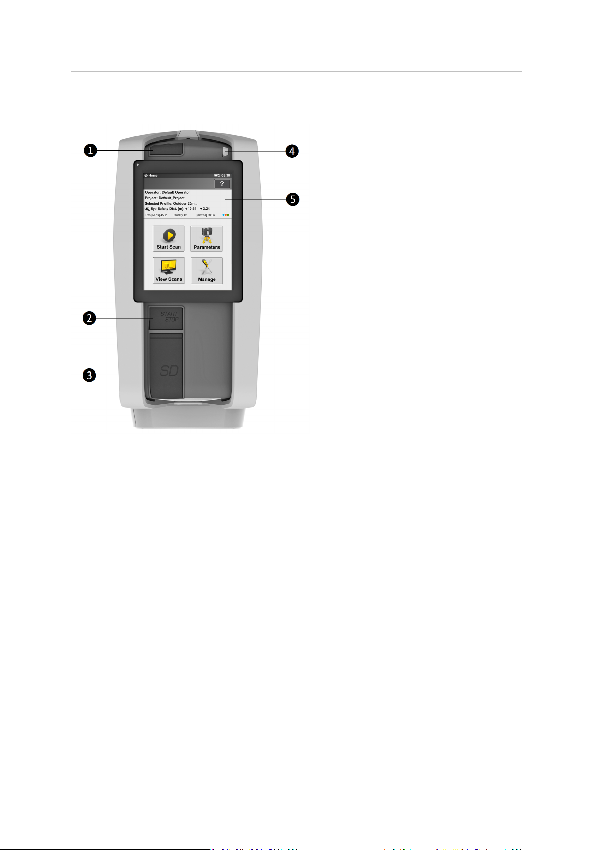
3 Parts and their Functions
Scanner – right side
Power button
❶
Press this button to power on the laser scanner. If the laser scanner is on and
running, press this button to powerdown the laser scanner.
Pressing and holding the button more than 4 seconds will switch offthe laser
scanner without shutting down. Only use this option in exceptional cases; for
example, ifthe shutdown mechanism does not work or the laser scanner is
non-responsive.
START/STOP button
❷
Press this button to start or stop recording a scan.
SD memory slot and cover
❸
Open the cover to insert a card into or release a card from the card slot. For
more information, see Using an SD memory card, page 38.
❹ LEDon mirror side of the scanner
❺ Touch screen display
Trimble TX5 3D Laser Scanner User Guide 27
Page 28
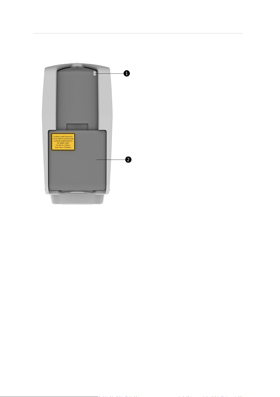
3 Parts and their Functions
Scanner – left side
❶
LED sensor side
❷ Battery compartment
Open the cover and press the fastener to release the battery
Trimble TX5 3D Laser Scanner User Guide 28
Page 29
3 Parts and their Functions
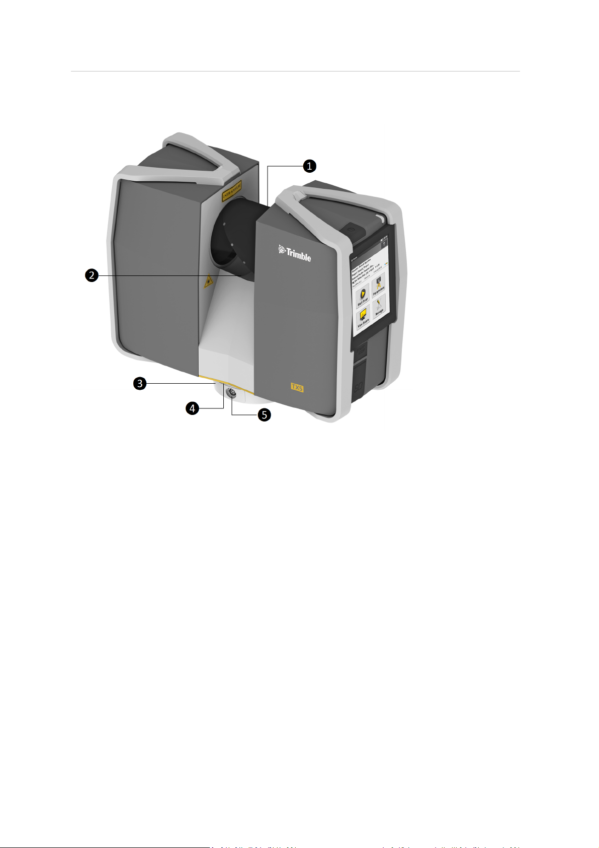
Scanner – front
Scanner mirror
❶
For safety and cleaning instructions see Mechanical security, page 22and
Cleaning instructions for optics, page 23.
Reference area
❷
Used to adjust distance measurements while scanning. Avoid soiling this area
and do not touch it.
Scanner mount
❸
See Scanner – bottom, page 30.
LEDon scanner mount
❹
Power socket
❺
For the pin assignment of the power socket, see Laser scanner power socket,
page 117.
Trimble TX5 3D Laser Scanner User Guide 29
Page 30
3 Parts and their Functions
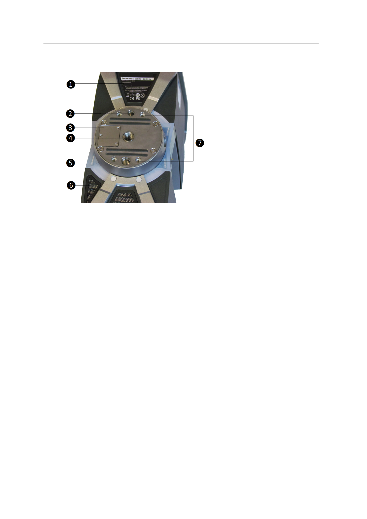
Scanner – bottom
❶ Type label
❷ Pin hole (diameter 6 mm) for scanner adjustment
Cover of the automation interfacefor automated applications
❸
Remove to get access to the automation interface of the laser scanner. For
more information, refer to the Trimble TX5 Automation Interface Guide.
Cover the automation interfaceif it is not needed or not in use.
❹ 3/8” screw thread to mount the scanner to standard photo tripods
❺ Pin hole (diameter 8 mm) for scanner adjustment
Cooling fan openings
❻
Keep these openings uncovered to ensure proper cooling of the scanner
❼ M5 screwthreads to mount the scanner to customer specific fixtures
For a detailed sketch of the scanner mount, see Mount dimensions, page 115.
Trimble TX5 3D Laser Scanner User Guide 30
Page 31
3 Parts and their Functions
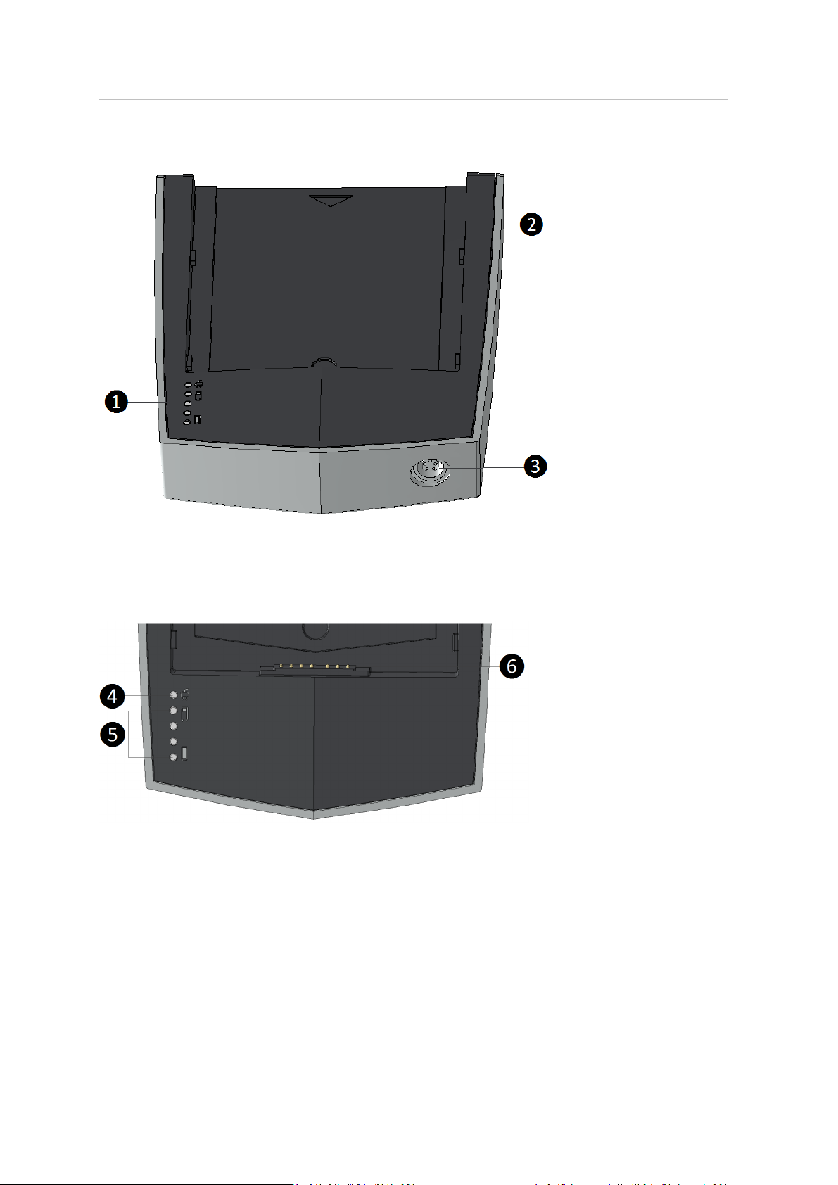
PowerDock battery charger cradle
LEDs (see below)
❶
Bearing area for the battery
❷
Power socket
❸
❹
Power LED (LED 1). Indicates that power is connected to the PowerDock.
❺
LEDs 2–5. Indicate the charging status of the battery.
❻
Connectors
Trimble TX5 3D Laser Scanner User Guide 31
Page 32

3 Parts and their Functions
Normal LEDbehavior
Charge
level
0–25% LED 2 is blinking yellow, others are off
25–50% LED 2 is illuminating yellow, LED 3 is blinking yellow, LEDs 4 & 5
50–75% LEDs 2 & 3 are illuminating yellow, LED 4 is blinking yellow, LED
75–99% LEDs 2 to 4 are illuminating yellow, LED 5 is blinking yellow
Fully
charged
LED behavior
are off
5 is off
LEDs 2 to 5 are illuminating yellow
LEDbehavior in case of errors
Error LED behavior
Temperature too low LED 2 is blinking red
Temperature too high LED 5 is blinking red
Battery is defective LEDs 2 to 5 are blinking red
Power supply has under-or over- voltage LED 1 is blinking red
Trimble TX5 3D Laser Scanner User Guide 32
Page 33

C H A P T E R
4
4Getting Started
In this chapter:
n
Charging the battery
n
Setting up the tripod
n
Mounting the laser scanner
n
Using an SD memory card
n
Powering the laser scanner
n
Powering on the laser scanner
n
Initial scanner settings
n
Scanning
n
Shutting down the laser scanner
n
Powering off the laser scanner
This chapter provides preliminary steps and
basic laser scanner operations and will guide
you step-by-step from setting up the laser
scanner to recording your first scan.
Trimble TX5 3D Laser Scanner User Guide 33
Page 34

4 Getting Started
Charging the battery
The PowerBlock battery can be charged in the laser scanner or in the PowerDock battery charger
which is available as an optional accessory. Carefully read the safety measures described in
PowerBlock battery safety, page 15 and PowerDock battery charger safety, page 16 before using
them.
It is recommended to fully charge the battery before use and that a spare battery is kept on hand
just in case it is needed during your scan project.
Charging the battery in the laser scanner
The laser scanner doesn't need to be switched on in order to charge the battery.
1. Mount the battery into the laser scanner. See Supplying power with the battery, page 39.
2. Connect the AC adaptor to the laser scanner and the wall outlet. See Supplying powerwith the
external power supply unit, page 40.
3. If the laser scanner is turned off, the upper LEDs on both sides of the scanner as well as the
LEDs at the scanner mount willstart blinking slowly yellow while charging. The LEDs will stop
blinking and willilluminate constantly yellow when the battery is fully charged.
4. If the laser scanner is turned on, you can check the exact charge state of the battery in the
scanner's user interface under Manage / General Settings / Power Management.
Note:
l
Take out the laser scanner from the transport case before connecting the power supply to the
scanner.
l
Use the power supply unit indoors only.
l
Before longer storage, remove the power supply unit and the battery from the laser scanner.
Tips for using the battery
Charge the battery the day it is to be used or on the day before. A charged battery unused will
gradually lose power over time.
If the battery becomes exhausted quickly after being fully charged, replaceit with a new one.
For best battery performance, an ambient temperature of 5°C (41°F) to 35°C (95°F)is recommended.
In colder or warmer locations, battery performance and operation time may temporarily decrease.
Charging the battery with the PowerDock battery charger
The charger can be used in foreign countries. It is compatible with a 100V AC to 240V AC 50/60 Hz
power source. Use a plug adapter for other countries.
Trimble TX5 3D Laser Scanner User Guide 34
Page 35
4 Getting Started
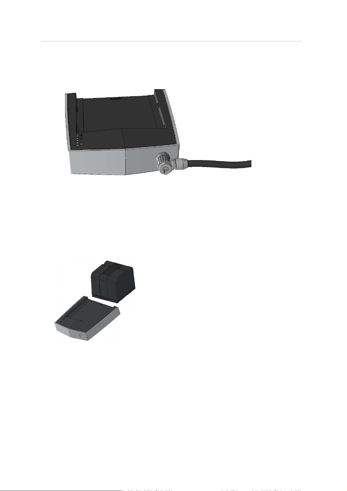
1.
Connect the power supply unit cable to the powersocket of the PowerDock charger. Confirm
the direction of the power supply's plug. If you forcibly insert the plug in a wrong direction, the
plug, the charger's power socket as wellas the charger itself can be damaged.
2.
Connect the AC power cable to the power supply as wellas to a power outlet. Check the input
voltage on the type label beforeconnecting. LED 1 of the PowerDock charger should illuminate
yellow, which means that power is connected to the charger.
Note – The power supply unit and the PowerDock charger are not for outdoor use. To avoid
electrical shock, use them in dry indoor environments only.
3.
Point the battery's contacts to the PowerDock charger and placethe battery flat along the
arrow mark on the charger and slide it carefully into charging position until it snaps into place.
Make sure that the battery's pins are in contact with the charger's terminals.
Charging starts automatically as soon as the battery has been inserted into the charger; LEDs 2
to 5 blink and illuminate according to the current charging state of the battery. For more
information, see PowerDock battery charger cradle, page 31.
4. After charging, carefully slide the battery out of position and remove it.
Trimble TX5 3D Laser Scanner User Guide 35
Page 36

4 Getting Started
Setting up the tripod
Extend and lock all legs of the tripod. Check that the tripod adjustment arrangements have been
locked and that the legs are of even length. Ensure that the surface is stable, that the tripod feet are
secured and that it is firm in its position. The tripod‘s plate should be levelled as horizontally as
possible.
In extreme windy conditions, make sure that the tripod has a stable standing. For this, you should
affix a heavy weight to the tripod or sandbag its feet.
The Gitzo carbon fiber tripod, shown below, is an optional accessory.
Trimble TX5 3D Laser Scanner User Guide 36
Page 37
4 Getting Started
Mounting the laser scanner
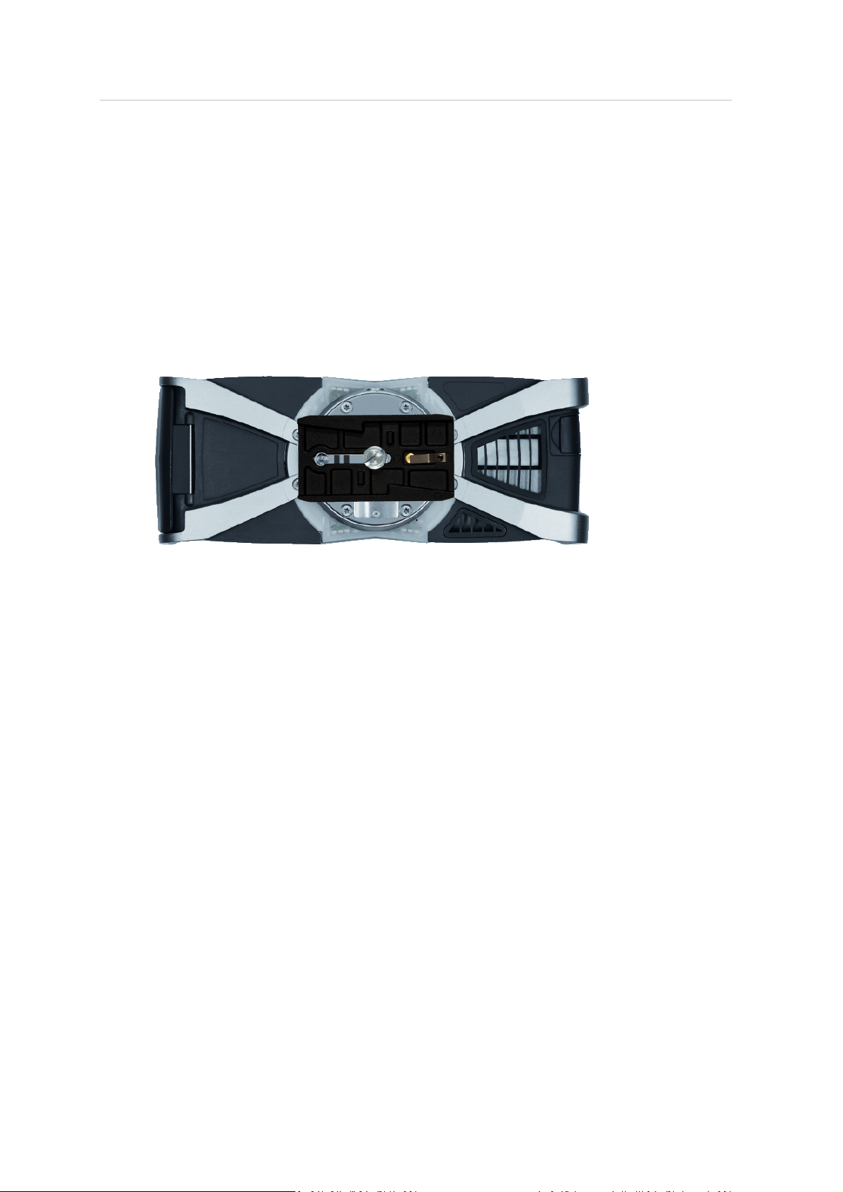
To mount the laser scanner to a tripod we recommend using a standard photo camera quick
release. The quick release's plate must be equipped with a 3/8” screwto fit into the scanner's
mount.
1. Remove the laser scanner from the case, check outer casing for any signs of damage or
distortion. Check mirror for damage due to scratches, cracks, distortion and inspect for
cleanliness.
2.
Attach the quick release's plate with its 3/8” screwto the scanner's mount. Make sure to
tighten the screw.
3. Mount the counter piece of the quick release onto the tripod. Make sure that it is fixed
securely.
4. Carefully mount the laser scanner with the attached quick release plate to its counter piece and
lock its fastener. Test that the scanner is correctly locked in placeby gently attempting to lift it
from the tripod.
5. The scanner should be set up as horizontally as possible. The levelling may be refined using the
integrated dual axis compensator. See Inclinometer (Dual Axis Compensator), page 101.
Refer to the user manual of your quick release for detailed instructions.
Trimble TX5 3D Laser Scanner User Guide 37
Page 38
4 Getting Started
Using an SD memory card
Preparing an SDmemory card
The laser scanner willstore the recorded scans on a removable SD memory card. This memory card
can also be used to create backups of the scanner settings, to import scanner settings and to install
firmware updates.
Before carrying out a scan project you may use TX5 SCENE software to set up an SD card with
project relevant information and settings, like the project structure, scan profiles or scanner
operators. These settings can then be transferred to the scanner. For more information on scan
project preparation with TX5 SCENE software and transferring data to the scanner, see SD Card,
page 95 and also refer to the Trimble TX5 SCENESoftware User Guide.
You can use SD, SDHC or SDXC cards. Memory cards with a size up to 64 GB have been verified to
operate with the scanner. We recommend using memory cards with a capacity of 4 GB or more. The
speed of the card should be Class 6 or better and its temperature range should be from -20°C (-4°F)
to 85°C (185°F).
Note – All used SD cards must be formatted in the FAT32 file system. When using an SD card other
than the supplied one, format it with the scanner‘s format function first. For more information, see
SD Card, page 95.
SD and SDHC cards may also be formatted with Windows as FAT32. SDXC cards with a capacity of
more than 32GB cannot be formatted with the Windows format function as Windows formats those
cards in its own filesystem, which is not supported by the scanner. Freewaretools that allow
formatting such cards with Windows as FAT32 areavailable, but Trimble recommends using the
scanner's format function.
CAUTION – Do not remove the SD card from the scanner while it is busy, otherwise you risk corrupting the data
on the card. A busy SD card is indicated by this icon blinking in the status bar of the operating software. It is safe
to remove the SD card from the scanner when this icon has disappeared from the status bar.
A busy SDcard icon: .
CAUTION – When removing an SD card from your computer, you should always use the Safely Remove Hardware
option from the system tray, otherwise you risk corrupting the data on the SD card.
For information on the folder and file structure of a memory card, see File structure of the SD
memory card, page 112.
Trimble TX5 3D Laser Scanner User Guide 38
Page 39

4 Getting Started
Inserting the SD memory card
1. Open the SD memory card slot cover.
2. Insert the formatted SD card with the notched edge in the direction as illustrated until it clicks.
3. Confirm the direction of the memory card. If you forcibly insert the memory card in a wrong
direction, the SD card, the card slot or data on the card can be damaged.
4. Close the cover.
Ejecting the SD memory card
To remove a SD card from the scanner, open the SD card slot cover and lightly push the memory
card.
l
Do not eject the memory card during scanning or firmware updates.
l
Take care that the memory card does not pop out and drop.
Powering the laser scanner
The laser scanner can be operated with the battery and the external power supply unit.
Supplying power with the battery
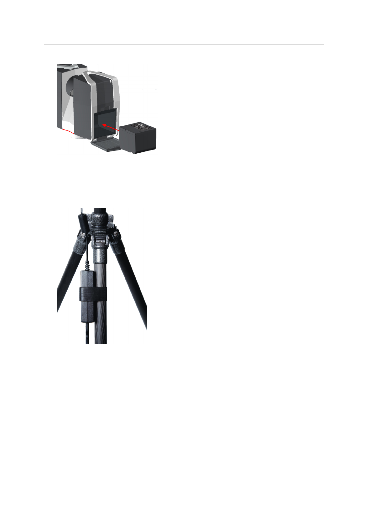
Adhere to the battery safety measures (see PowerBlock battery safety, page 15)and mount a
charged battery into the laser scanner:
1. Open the scanner's battery compartment cover.
2.
Turn the battery so that its type labelis directed upwards, point the battery contacts to the
scanner, push the battery straight in, and slide it downward into the battery compartment
until the fastener clicks into position.
Trimble TX5 3D Laser Scanner User Guide 39
Page 40
4 Getting Started
3. Close the battery cover.
Supplying power with the external power supply unit
1.
Attach the power supply to one of the tripod's legs.
2.
Connect the power supply unit cable to the powersocket of the laser scanner. Confirm the
direction of the power supply's plug. If you forcibly insert the plug in a wrong direction, the
plug, the scanner's power socket, as well as the scanner can be damaged.
Trimble TX5 3D Laser Scanner User Guide 40
Page 41

4 Getting Started
3.
Connect the AC power cable to the power supply as wellas to a power outlet. Check the input
voltage on the type label beforeconnecting. The upper LEDs of the scanner on the mirror and
sensor side as wellas the LED of the scanner mount begin to illuminate yellow.
Note – To avoid electrical shock, outdoor use of the power supply unit is not permitted. Use
the power supply unit in dry indoor environments only.
Trimble TX5 3D Laser Scanner User Guide 41
Page 42
4 Getting Started
Powering on the laser scanner
Pressing the scanner's Power button will start the boot process, which willbe indicated by the
scanner LEDs blinking yellow.
If power is supplied by the battery only and its charge state is too low to start the scanner, the
scanner LEDs will blink orange.
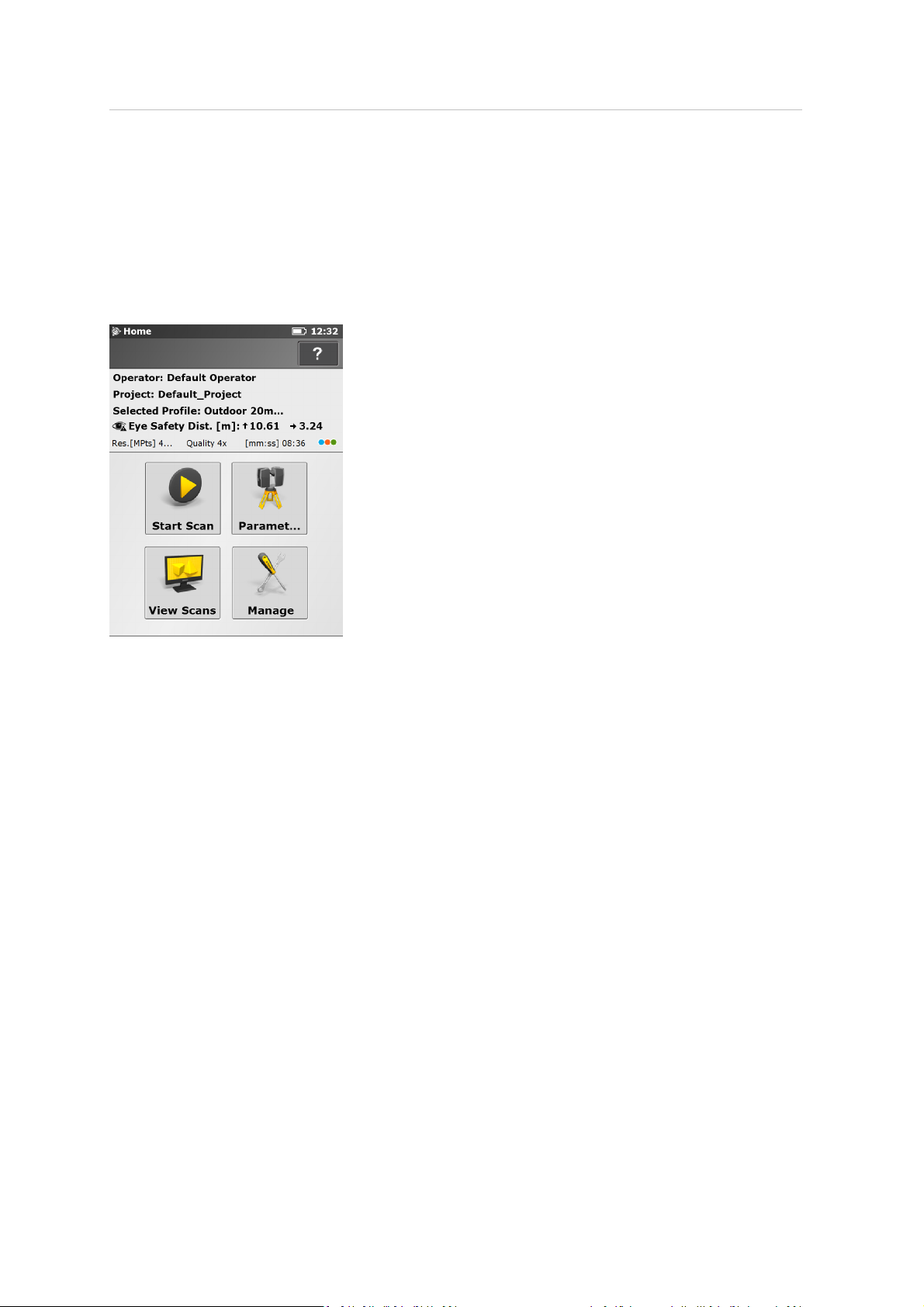
When the laser scanner is ready, the LEDs stop blinking and illuminate yellow and the Home screen
of the scanner's operating software willappear on the integrated touch screen.
The laser scanner can be operated to its full extent by simply touching the elements on the screen
with your fingers. You can also use a stylus, if you prefer.
Trimble TX5 3D Laser Scanner User Guide 42
Page 43

4 Getting Started
Initial scanner settings
This section gives you a brief description on how to set up initialscanner settings using the scanner's
operating software on the integrated touch screen:
l
Setting the interface language, page 44
l
Setting the date and time, page 44
l
Setting the date format, page 45
l
Changing the date and time, page 45
l
Setting the unit of length and the temperature scale, page 46
l
Entering scanner information, page 47
For more information, see TX5 Controller Software, page 69.
Trimble TX5 3D Laser Scanner User Guide 43
Page 44
4 Getting Started
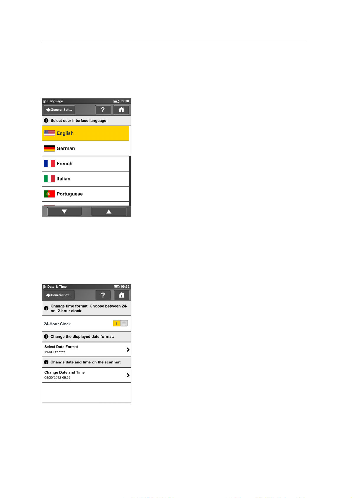
Setting the interface language
Starting from the Home screen, go to Manage / General Settings / Language to change the
language of the operating software.
To set the language, tap the language in the list. The selected language is highlighted.
If the list of available languages exceeds the screen size, scroll the list up or down using the arrow
buttons.
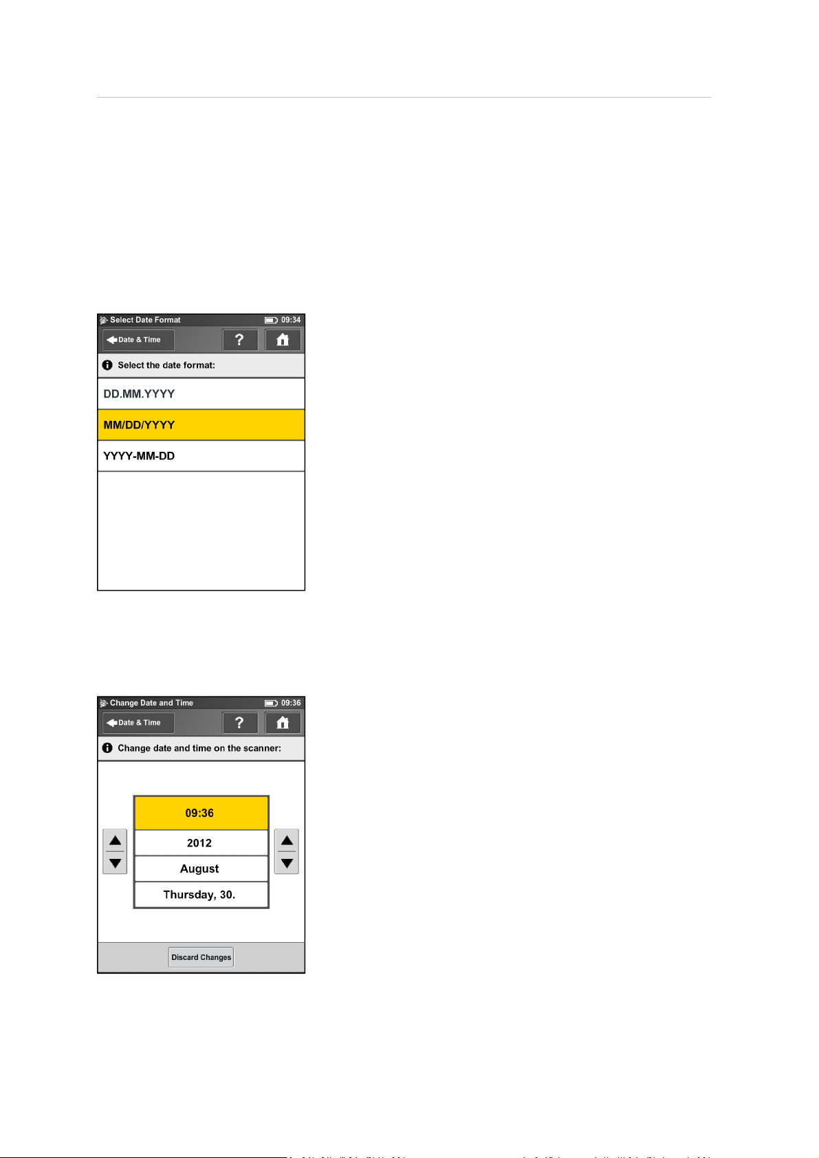
Setting the date and time
To change the date and time settings, go to Manage / General Settings / Date & Time.
Trimble TX5 3D Laser Scanner User Guide 44
Page 45
4 Getting Started
Time Format – Tap to set the time format. The operating softwareshows the time in 24-hour or 12hour format. Switch the button to ON to select the 24-hour clock. Switch the button to OFF to select
the 12-hour clock.
Selected date format – Tap to choose the date format. The currently selected date format is
displayed on the button itself.
Change date and time – Tap to set the internal clock of the laser scanner.
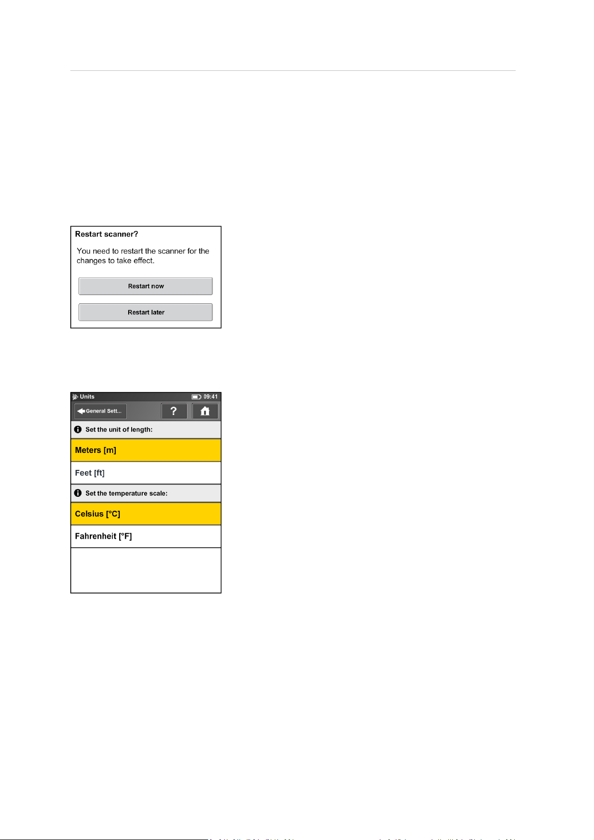
Setting the date format
To select the date format, tap the format in the list. YYYY is the year, DD the day and MM the
month. The selected format is highlighted.
Changing the date and time
Trimble TX5 3D Laser Scanner User Guide 45
Page 46
4 Getting Started
Select the Time button in the list to change the time, then use the buttons on the left to set the
hours, the buttons on the right to set the minutes.
Select the Year button in the list to change the year, then use the buttons on the left or on the right
to set the date.
Proceed accordingly with the Month and the Day buttons.
Click Discard Changes to discard your changes.
To apply your changes, leave the screen using the Back or Home button. A message warns if you
need to restart the scanner for the changes to take effect.
Setting the unit of length and the temperature scale
You can change the units scale under Manage / General Settings / Units.
Lengths are displayed in meters or in feet.Tap a unit of length to select it.
Temperatures are displayed in Celsius or Fahrenheit.Tap a temperature scale to select it.
Trimble TX5 3D Laser Scanner User Guide 46
Page 47
4 Getting Started
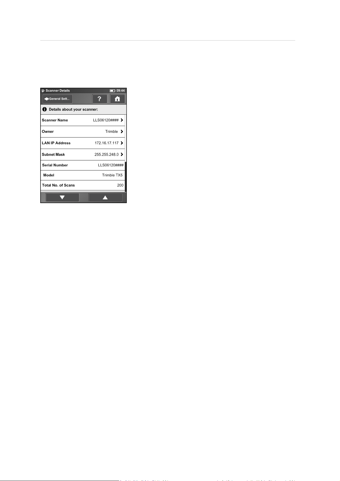
Entering scanner information
To specify a scanner name and the owner, go to Manage / General Settings / Scanner Details.
Scanner name – Tap to change the name of the scanner.
Owner – Tap to enter the name of the company or person who owns the scanner. For more
information, see Scanner Details, page 92.
Trimble TX5 3D Laser Scanner User Guide 47
Page 48

4 Getting Started
Scanning
This section provides a briefdescription on how to change the scanning settings so that you can
capture your first scans.
l
Setting the scan parameters, page 49
l
Scanning parameters overview, page 60
l
Enhancing the scanning environment with artificial targets, page 62
l
Environmental conditions, page 64
l
Starting a scan, page 65
For more information, see TX5 Controller Software, page 69.
Trimble TX5 3D Laser Scanner User Guide 48
Page 49
4 Getting Started
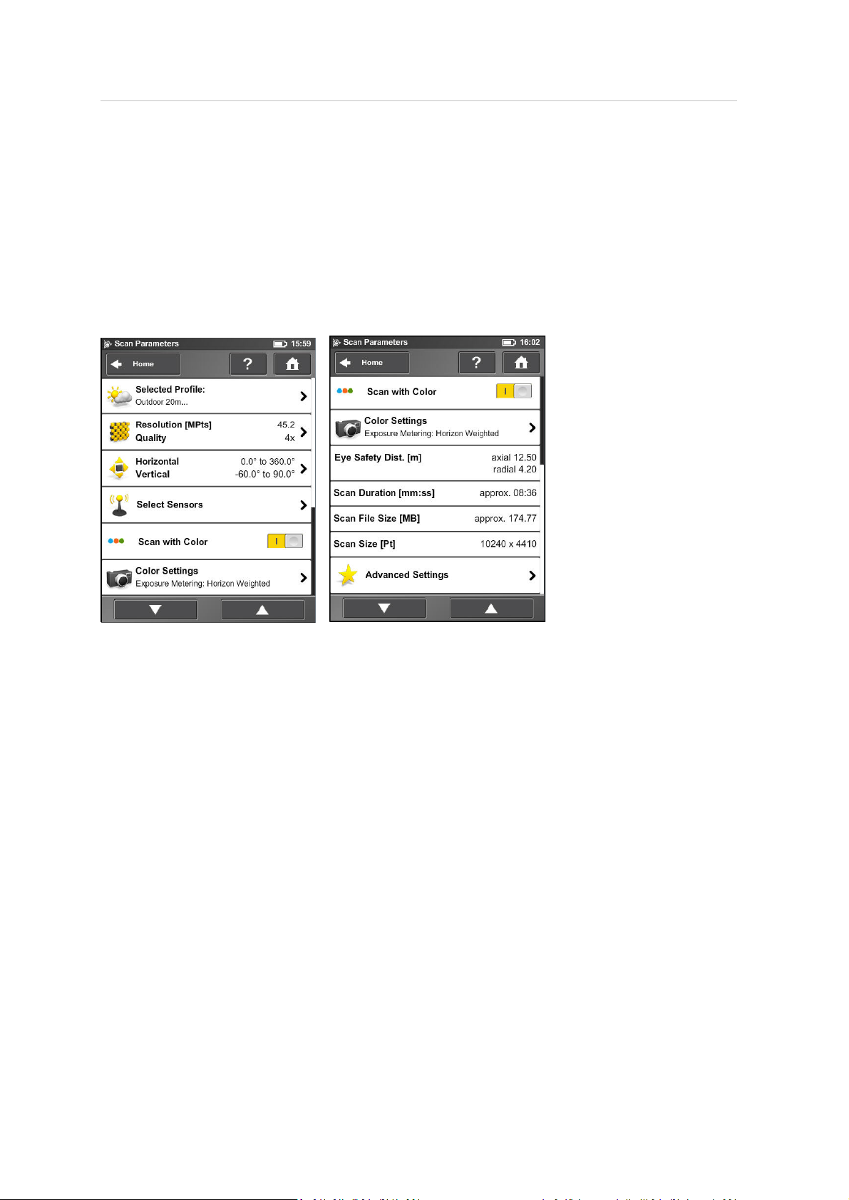
Setting the scan parameters
Scanning parameters like resolution, quality or the scanning angles are the parameters used by the
scanner for recording the scan data. There are two ways to set the scanning parameters: Change
them manually or select a scan profile which is a predefined set of scanning parameters. When
selecting a scan profile, the scanning parameters willbe overwritten by the settings of this scan
profile.
To choose a predefined scan profile or to change the scanning parameters manually tap the
Parameters button on the Home screen.
Selected Profile – Shows the name of the selected scan profile. Tap to select a scan profile. If the
scanning parameters differ from the selected profile, altered is appended to its name. Selecting a
scan profile overwrites the scanning parameters with the settings of this scan profile.
Resolution and Quality – Displays the selected resolution in Mega points and the selected quality.
Tap to change these values.
Horizontal and Vertical Scan Range – Displays the scan range with the horizontal and the vertical
start and end angles in degrees. Tap to adjust them.
Select Sensors – Tap to enable or disablethe automatic use of data from the built-in sensors for scan
registration in TX5 SCENEsoftware.
Note – The available sensors vary depending on the scanner model.
Scan with Color – Switch colored scan recording on or off. If switched on, the scanner also takes
color photos of the scanned environment with the integrated color camera. These photos are taken
right after the laser scan and are used in the SCENEpoint cloud processing softwareto automatically
colorize the recorded scan data.
Color Settings – Shows the current exposure metering mode used for taking the color photos. Click
to change the exposure metering mode. For more information, see Color settings, page 54.
Trimble TX5 3D Laser Scanner User Guide 49
Page 50
4 Getting Started
Eye Safety Distance – The axial and radial eye safety distance (NOHD). Both values depend on the
selected resolution and quality setting. For more information, see Laser safety, page 17.
Scan Duration, Scan File Size – Expected scan time and file size in Megabytes according to the
chosen resolution, quality value, and scan range. The values shown here are approximate values for
scan time and do not take into account the time required to capture color photos.
Scan Size [Pt] – Shows the size of the scan in points horizontally x vertically. The vertical size may
only be changed by setting a new resolution or by changing the scan area angle.
Advanced Settings – Enable or disable the Clear Contour and Clear Sky filters.
Selecting a scan profile
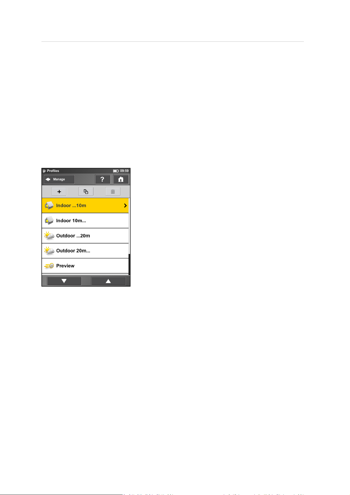
Prior to capturing a scan, you may select a scan profilethat fits the needs of the scene and the
required scan quality.
This view shows a list of all available scan profiles. This list contains factory predefined profiles which
are read-only and custom profiles which can be created and manipulated under Manage Profiles.
For more information, see Creating a scan profile, page 80.
Tap a profile to select it. The selected profile is highlighted. To view the details of the selected profile,
tap it again. For an overviewof the availablefactory predefined scan profiles, see Factory predefined
scan profiles, page 82.
Trimble TX5 3D Laser Scanner User Guide 50
Page 51
4 Getting Started
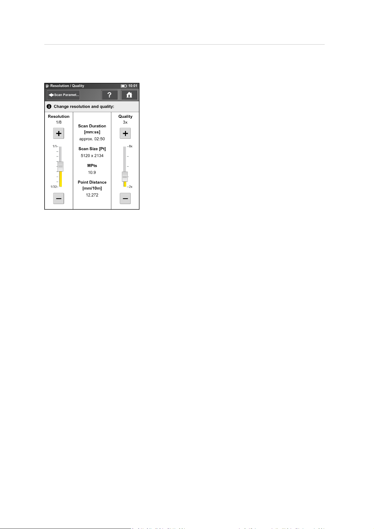
Setting resolution and quality
Resolution – The resulting scan resolution. You can choose among 1/1, 1/2, 1/4, 1/5, 1/8, 1/10,
1/16, 1/20 and 1/32. Use the slider on the left to change the resolution of the next scan.
Quality – Affects the quality of the scan and the scanning time at constant scan resolutions. Move
the slider up to reduce the noise in the scan data and increases the scan quality. This results in a
longer scanning time. Move the slider down to reduce the scanning time and increase the efficiency
of your scan project. The Quality slider sets quality levels either via diverse measurement rates or by
applying additional noise compression. For more information, see Scanning parameters overview,
page 60.
The resulting scan duration, verticaland horizontal scan points (Scan Size [Pt]), as well as the
resulting scan size in Mega points (MPts) are displayed in the middle of the view. Point Distance
[mm/10m] / [in/30ft] is the distance between the captured scan points in mm (in) in a scan distance
of 10 meters (30 ft.).
Depending on the chosen scan resolution only appropriate quality values are selectable (see
Scanning parameters overview, page 60).
If you plan to capture severalscans from the same position (with different resolutions) and if it is
important that these scans have the same horizontal start angle, then you should not switch off the
scanner or change the quality between the recordings of these scans.
Trimble TX5 3D Laser Scanner User Guide 51
Page 52
4 Getting Started
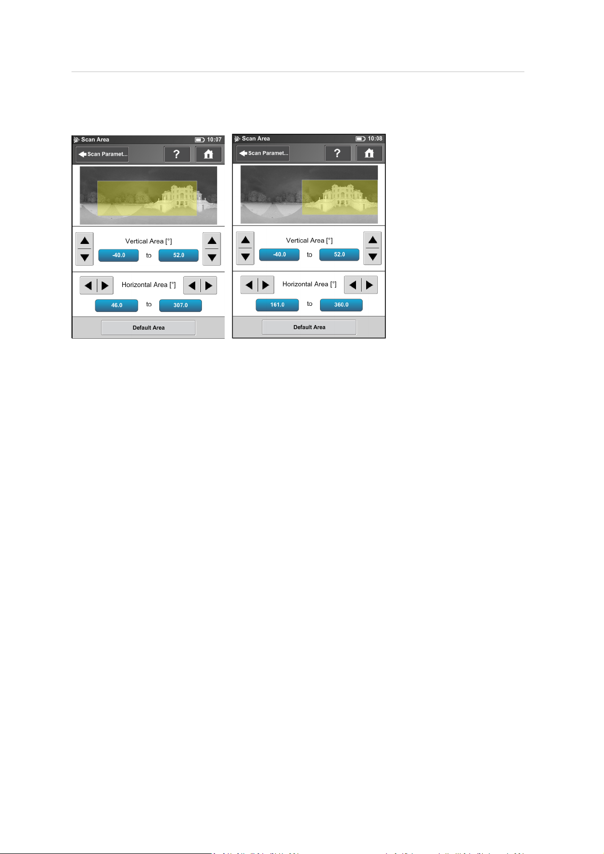
Setting the scan range
Vertical area – The size of the vertical scan area in degrees. Use the left up and down buttons to
change the verticalstart angle. Use the right up and down buttons to adjust the verticalend angles.
Horizontal area – The size of the horizontal scan area in degrees. Use the left buttons to change the
horizontal start angle. Use the right buttons to adjust the horizontal end angles.
Default Area button – Tap to reset the values to the default scan area (vertical from -60° to 90° and
horizontal from 0° to 360°).
The rectangle in this view illustrates the fullscan area. If therearescans on the inserted SD card, the
preview picture of the last recorded scan is displayed. If there is no preview picture available, a grid
is displayed, where the space between the horizontal and verticallines is equivalent to 30°. The
yellow rectangle illustrates the selected scan area.
Trimble TX5 3D Laser Scanner User Guide 52
Page 53
4 Getting Started
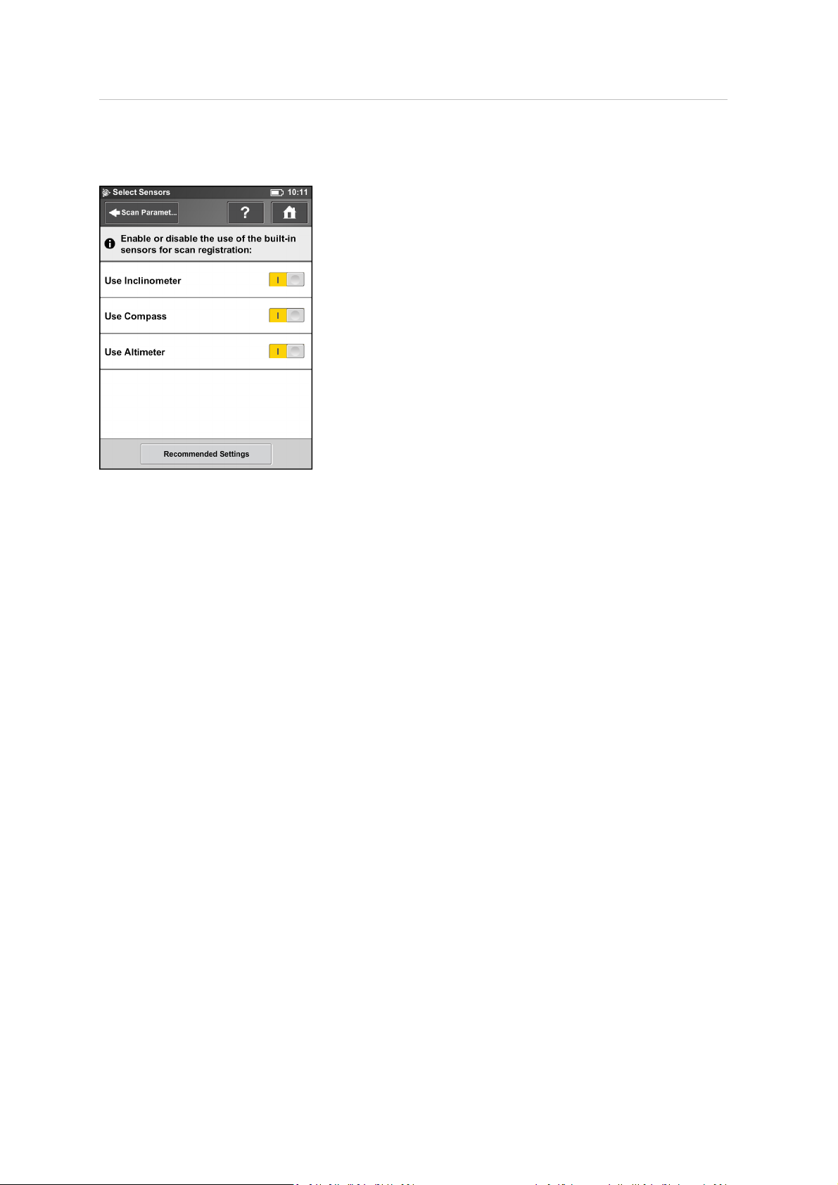
Selecting the sensors
Use Inclinometer – Enable or disable the automatic use of the inclination measurement of the builtin dual axis compensator (inclinometer) for scan registration in TX5 SCENE software. However, the
data of this sensor is always measured and attached to each scan. If the use of the inclinometer data
is switched ON, it is automatically used to register the scans in TX5 SCENE software; ifit is switched
off, the data is ignored. You can change this behavior later in the TX5 SCENE software. For more
information, refer to the Trimble TX5 SCENESoftware User Guide.
Note – To get the most reliable data from the dual axis compensator, make sure that the
scanner‘s inclination is less than 5°. For more information, see Inclinometer (Dual Axis
Compensator), page 101.
Use Compass – Enable or disable the automatic use of data from the built-in compass for scan
registration in TX5 SCENEsoftware. The data of the compass is always measured and attached to
each scan during scanning. If this button is switched to ON the data is automatically used for scan
registration. For more information, see Compass, page 102.
Use Altimeter – Enable or disable the automatic use of altimeter data for scan registration in TX5
SCENE software. The data of the altimeter is always measured and attached to each scan during
scanning. If this button is switched to ON the data is automatically used for scan registration. You
may want to enter a reference height before starting your scan project. This reference height then
acts as basis for all measurements made by the altimeter. Altimetersettings are in Manage /
Sensors / Altimeter. For more information, see Altimeter, page 103.
Click the Recommended Settings button to enable the use of all sensors.
Trimble TX5 3D Laser Scanner User Guide 53
Page 54
4 Getting Started
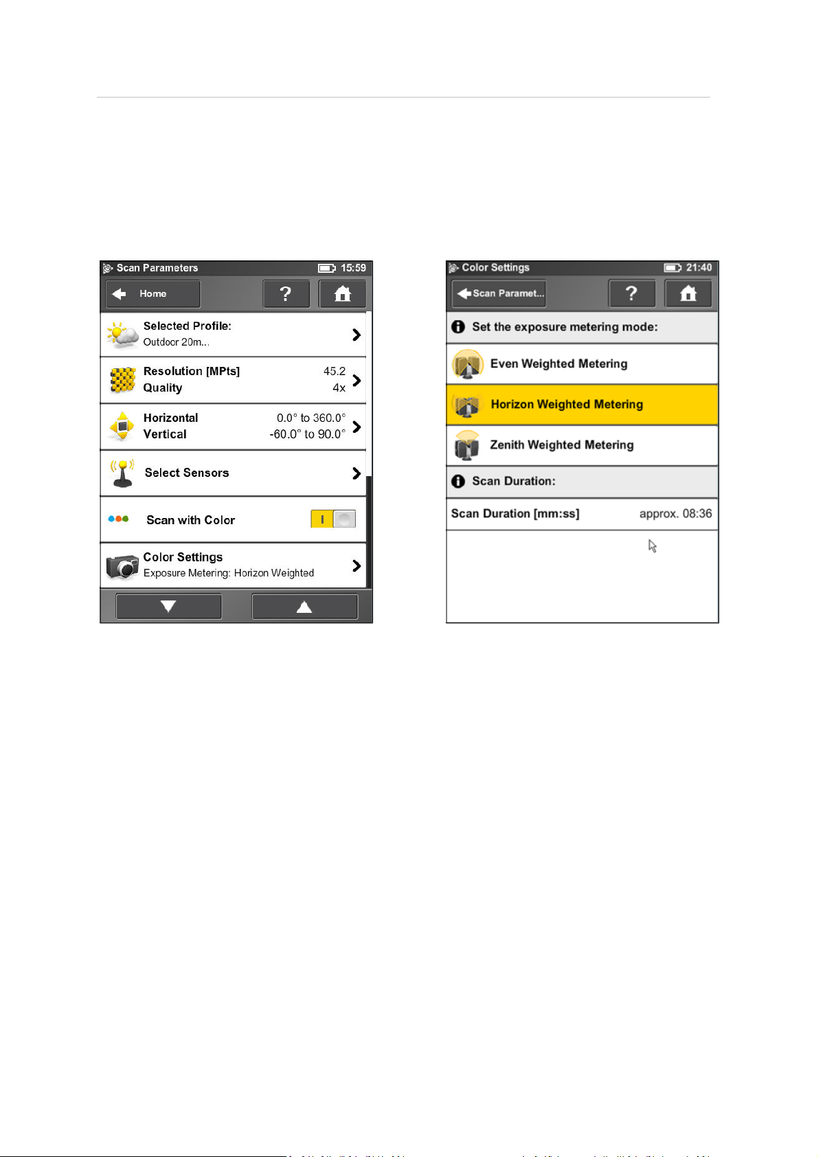
Color settings
Select Parameters / Color Settings to set the way in which the integrated color camera determines
the exposure for taking the color photos if colored scan recording is switched on. To set the
exposure metering mode, select between three modes to meet the requirements of the current
lighting conditions and to get best possible results for the area of interest.
Trimble TX5 3D Laser Scanner User Guide 54
Page 55
4 Getting Started
Even weighted metering
To determine the exposure settings, the camera uses the light information coming from the entire
scene and averages it without giving special weighting to a particular area. Use this setting in
scenarios with even lighting conditions.
Trimble TX5 3D Laser Scanner User Guide 55
Page 56
4 Getting Started
Horizon weighted metering
With horizon weighted metering mode, the camera uses the light information coming from the
horizon to determine its exposure setting. This mode is commonly used in scenarios with bright
light coming from directly above (for example, indoors with bright ceiling lighting or outdoors with
bright sunlight coming from directly above) and enables you to achieve the most correct balance of
light and exposure for objects at the horizon. This mode is the default setting. Compared to the
even weighted metering mode, this mode increases the scan duration by approximately 14 seconds.
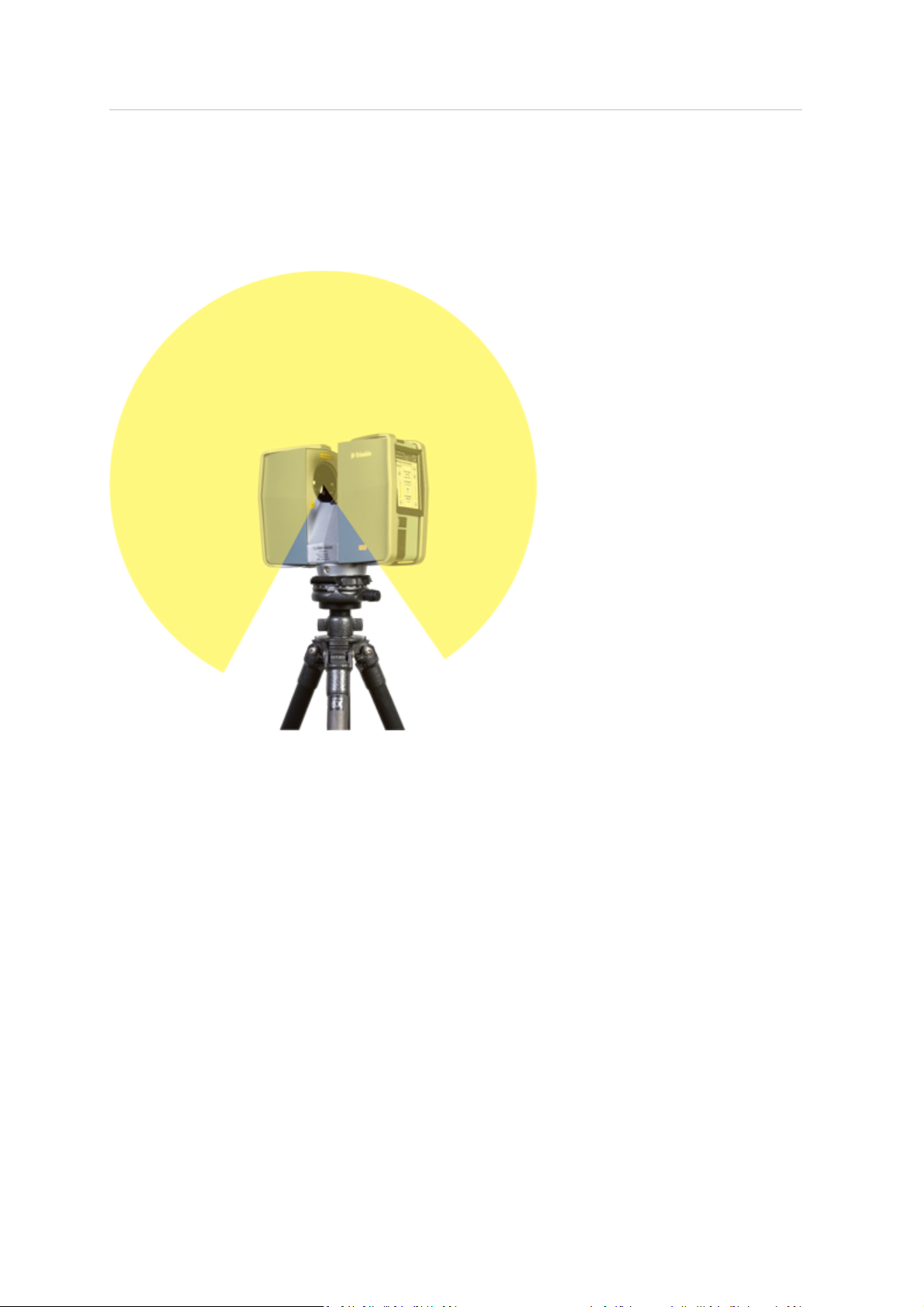
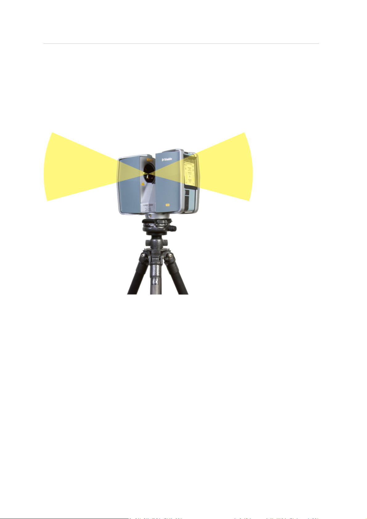
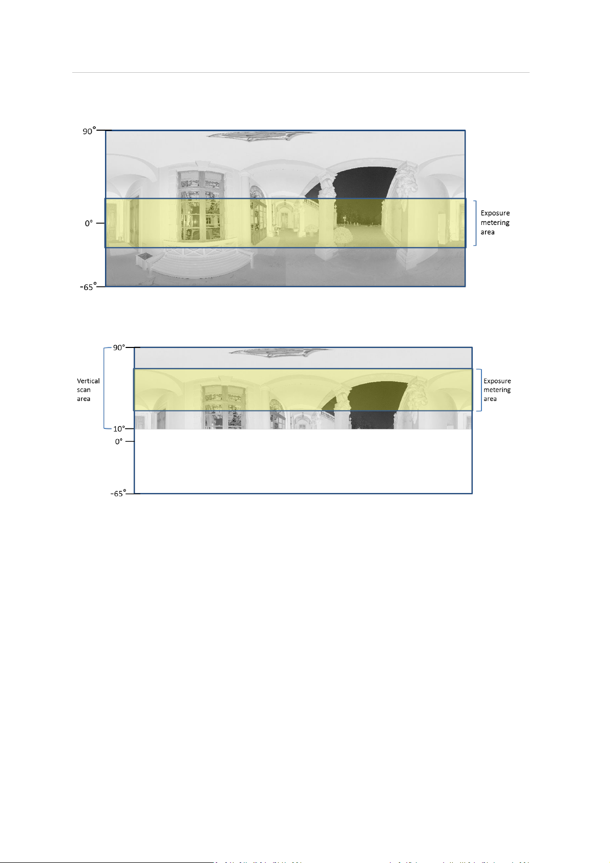
If the vertical scan area is limited, then the area used to determine the exposure (exposure metering
area)might move away from the horizon. This is the case if the vertical start angle is set to a value > 30° or ifthe verticalend angle is set to a value < 30°. The exposure metering area willthen be moved
up or down and set to the center of the remaining verticalscan area. The following images illustrate
this behavior.
Trimble TX5 3D Laser Scanner User Guide 56
Page 57
4 Getting Started
This image shows the exposure metering area (highlighted yellow)for the full vertical scan area:
This image shows the exposure metering area for a limited vertical scan area set to, for example, 10°
to 90°:
Trimble TX5 3D Laser Scanner User Guide 57
Page 58
4 Getting Started
Zenith weighted metering
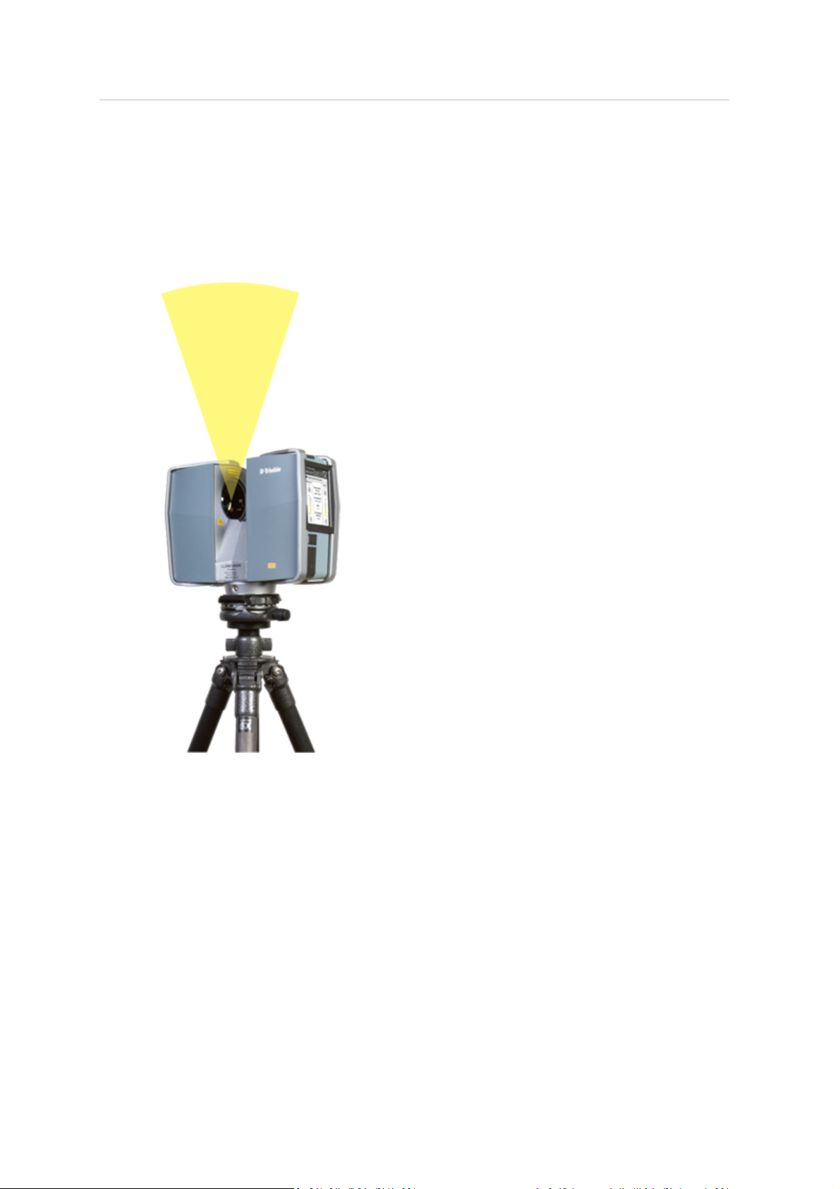
With zenith weighted metering mode, the camera uses the light information coming from above the
scanner to determine its exposure setting. Use this mode if there is very bright light coming from,
for example, windows and if you want to achieve the most correct balance of light and exposure for
objects at the ceiling of building (for example, ceiling paintings in historical buildings). Compared to
even weighted metering mode, this mode increases the scan duration by approximately 14 seconds.
Trimble TX5 3D Laser Scanner User Guide 58
Page 59
4 Getting Started
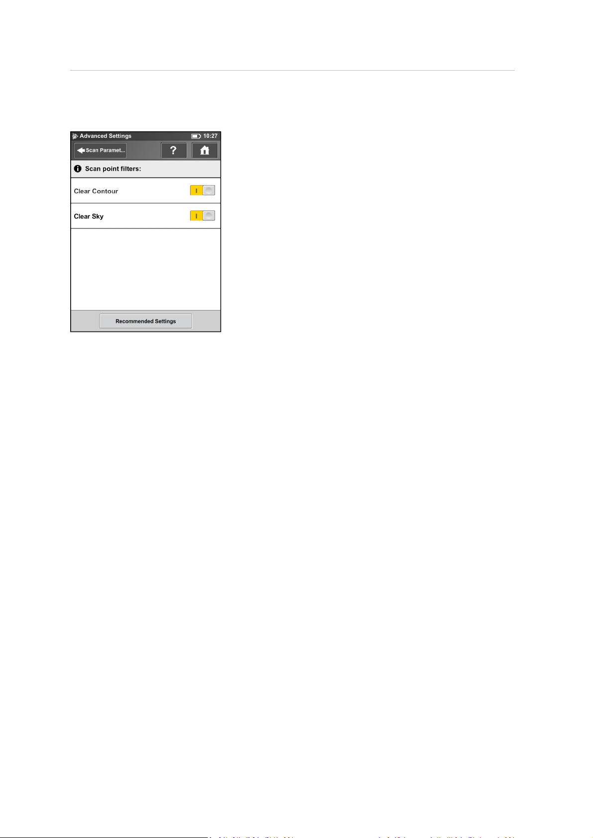
Advanced Settings
Clear Contour – Enables the dynamic contour filter. While scanning, this hardwarefilter removes
incorrect measurements at the edges of objects. It removes scan points resulting from hitting two
objects with the laser spot which mainly happens at the edges of objects.
Clear Sky – Enables the dynamic sky filter. While scanning, this hardwarefilter removes scan points
resulting from hitting no objects at all which mainly happens when scanning the sky.
Recommended Settings button – Enables both filters.
Trimble TX5 3D Laser Scanner User Guide 59
Page 60

4 Getting Started
Scanning parameters overview
The table below shows the measurement speed, noise compression, net scan time, and the axial
and radialNOHD for all the resolution and quality settings that are available.
Note – The scan duration shown in the Scan Parameters screen and the scan duration values
shown below view differ from each other, because the values shown below are pure net values and
the time needed for capturing photos in color mode and pre and post processing time are not
taken into account.
Resolution Quality Speed
Mio. Pts
(full scan)
(kpt/sec)
Noise
compression
Net scan time
(full scan)
pt/360° NOHD [m]
axial radial
710.7 1/1 1x 976 — 0:14:19 40,960 7.50 3.60
710.7 1/1 2x 488 — 0:28:38 40,960 12.50 6.30
710.7 1/1 3x 244 — 0:57:16 40,960 20.30 10.90
710.7 1/1 4x 122 — 1:54:32 40,960 29.40 16.20
177.7 1/2 1x 976 — 0:03:35 20,480 4.50 1.80
177.7 1/2 2x 488 — 0:07:09 20,480 7.50 3.20
177.7 1/2 3x 244 — 0:14:19 20,480 12.50 5.50
177.7 1/2 4x 122 — 0:28:38 20,480 20.30 8.30
177.7 1/2 6x 122 2x 1:54:32 20,480 29.40 16.20
44.4 1/4 1x 976 — 0:00:54 10,240 2.70 0.30
44.4 1/4 2x 488 — 0:01:47 10,240 4.50 1.60
44.4 1/4 3x 244 — 0:03:35 10,240 7.50 2.80
44.4 1/4 4x 122 — 0:07:09 10,240 12.50 4.20
44.4 1/4 6x 122 2x 0:28:38 10,240 20.30 8.30
44.4 1/4 8x 122 4x 1:54:32 10,240 29.40 16.20
28.4 1/5 2x 488 — 0:01:09 8,192 3.80 1.30
28.4 1/5 3x 244 — 0:02:17 8,192 6.30 2.20
28.4 1/5 4x 122 — 0:04:35 8,192
10.60
3.30
28.4 1/5 6x 122 2x 0:18:20 8,192 20.30 8.30
11.1 1/8 2x 488 — 0:00:27 5,120 2.70 0.20
11.1 1/8 3x 244 — 0:00:54 5,120 4.50 1.40
11.1 1/8 4x 122 — 0:01:47 5,120 7.50 2.10
11.1 1/8 6x 122 2x 0:07:09 5,120 12.50 4.20
11.1 1/8 8x 122 4x 0:28:38 5,120 20.30 8.30
7.1 1/10 3x 244 — 0:00:34 4,096 3.80 0.70
7.1 1/10 4x 122 — 0:01:09 4,096 6.30 1.70
7.1 1/10 6x 122 2x 0:04:35 4,096 10.60 3.30
Trimble TX5 3D Laser Scanner User Guide 60
Page 61

4 Getting Started
Resolution Quality Speed
Mio. Pts
(full scan)
(kpt/sec)
Noise
compression
Net scan time
(full scan)
pt/360° NOHD [m]
axial radial
7.1 1/10 8x 122 2x 0:18:20 4,096 20.30 8.30
2.8 1/16 3x 244 — 0:00:13 2,560 2.70 0.10
2.8 1/16 4x 122 — 0:00:27 2,560 4.50 0.90
2.8 1/16 6x 122 2x 0:01:47 2,560 7.50 2.10
2.8 1/16 8x 122 4x 0:07:09 2,560 12.50 4.20
1.8 1/20 4x 122 — 0:00:17 2,048 3.80 0.40
1.8 1/20 6x 122 2x 0:01:09 2,048 6.30 1.70
1.8 1/20 8x 122 4x 0:04:35 2,048 10.60 3.30
0.7 1/32 4x 122 — 0:00:07 1,280 2.70 0.10
0.7 1/32 6x 122 2x 0:00:27 1,280 4.50 0.90
0.7 1/32 8x 122 4x 0:01:47 1,280 7.50 2.10
Trimble TX5 3D Laser Scanner User Guide 61
Page 62
4 Getting Started
Enhancing the scanning environment with artificial targets
Before scanning, you should make sure that there willbe enough referenceobjects in the scans so
that there willbe no problems during the later registration process. References, or targets, are used
to register multiple individual scans that are each on their own coordinate system, onto a single,
aligned coordinate system. Although scan registration using TX5 SCENE software can be done purely
on the basis of natural targets, such as planes, walls, corners etc., we recommend to enhance the
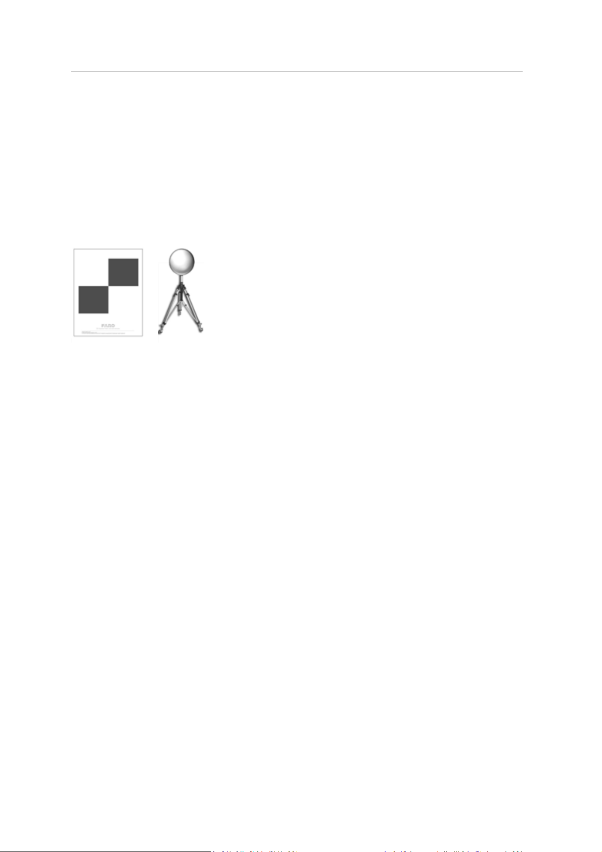
scanned environment with additional artificial referenceobjects, like spheres or checkerboard paper
targets. Spheres and paper targets can be combined within a scan site. Usually you will achieve
more precise registration results when you have manually placed such targets.
The following tips and hints provide an overviewof basic principles which should be obeyed when
working with artificialreferenceobjects like spheres or paper targets.
General
l
Mathematically you need three corresponding references in the two scans which you like to
register to each other. The inclination data captured by the built-in dual axis compensator may
serve wellas one reference, such that only 2 other scanner external references are required. But
a higher number of references per scan may improve the registration results and may make
registration easier and less error prone.
l
As artificialtargets you should use checkerboard targets or referencespheres.
l
Use targets with a non-reflecting surface.
l
Print paper references with laser printers only.
l
The references should be easily and clearly visible in the scans.
l
Targets should not be positioned symmetrically. They should form a polygon around the
scanner and have varying distances to the scanner. Place them in the scanning area at varying
heights, distances and planes. Avoid placing the targets in a straight line.
l
If the references cannot be placed in an adequate distance to the scanner, increase the
scanning resolution or the size of the targets.
l
Do not place targets in close proximity to one another. The distance between targets should
not be smaller than 1m.
l
Make sure you see the targets in more than one scan (ifyou do not have surveyed coordinates
for each targets). A target which is only visible in one scan is useless for registration.
Trimble TX5 3D Laser Scanner User Guide 62
Page 63

4 Getting Started
l
When capturing a chain of scans resulting in a tubular point cloud which is typical for e.g.
tunnel surveying, it is recommended to make use of the inclination sensor and references with
surveyed coordinates. Such references should be used along the entire chain. The scanner has
a certain measuring uncertainty and if you do not use surveyed references when capturing and
registering a chain of scans, this measuring uncertainty may propagate from scan to scan.
Checkerboard Targets
l
The angle of incidence between the laser beam and checkerboard targets should not be smaller
than 45°.
l
Depending on the chosen scanning resolution, the detection of checkerboard references in the
scans by the TX5 SCENEsoftware may be unreliablebeyond a certain distance to the scanner.
For example, when using A4 checkerboard references and scanning with a resolution of 1/4, the
distance to the scanner should not be greater than 15m. Larger distances can easily be
achieved by enlarging the size of the target or scanning with a higher resolution.
l
Checkerboard targets should not be rotated by 45° in relation to the scanner's axis.
l
Have sufficient scan points on the checkerboard targets. They need four or more scan points
per quadrant.
l
Checkerboard targets should not be attached to a curved surface.
Reference Spheres
l
Reference spheres should be completely visiblein the scan. Make sure that they are not partly
covered by other objects.
l
Depending on the chosen scanning resolution, the detection of sphere references by the TX5
SCENEsoftware may be unreliablebeyond a certain distance to the scanner. For example, when
scanning with a resolution of 1/4 and using spheres with a diameterof 145mm, the distance to
the scanner should not be greater than 18m. If you are using larger spheres, for example
spheres with a diameter of 200mm, the distance to the scanner may be extended to 45m.
For more information on registering scans and using references for registration, refer to the Trimble
TX5 SCENESoftware User Guide.
Trimble TX5 3D Laser Scanner User Guide 63
Page 64

4 Getting Started
Environmental conditions
l
When the product is transferred from a cold to a significantly warmer environment, water may
condense on some elements inside the scanner. To avoid this, we recommend placing the
scanner in an airtight plastic bag beforebringing it from a cold to a significantly warmer
environment. This allows the condensation to form on the bag and not inside the scanner. If
you do not have the possibility to pack the scanner airtight, wait until observable condensation
water evaporates from the scanner before switching on the laser scanner.
l
For applications requiring the highest degree of accuracy such as reverse engineering and
starting with the scanner at lower temperatures, it is advised to turn the scanner on and warm
it up until the internal temperature stabilizes.
l
If the temperature of the scanner is above or below the specified range, you willget a warning.
Scanning is still possible but the temperature may have impact on the measuring accuracy. If
an upper or lower temperature limit is exceeded, the scanner will automatically shut down to
avoid damages.
l
Strong dust formation, fog, rain or snowfallmay result in bad measurements. You should avoid
scanning under these conditions.
l
You should avoid scanning objects against direct sunlight. This may result in limited scan data
in this area.
l
Objects or surfaces may have an increased range noise if they are directly illuminated by bright
sunshine.
l
Highly absorbing or highly reflective surfaces increase the range noise and thus the measuring
inaccuracy. If these surfaces are of importance, you should treat them, for example with
developer or anti-glare-spray.
Trimble TX5 3D Laser Scanner User Guide 64
Page 65
4 Getting Started
Starting a scan
If you are in a distance less than the eye safety distance (NOHD), respect the laser safety measures
described in the laser scanner manual and in the appropriate national and regional regulation and
work place safety legislation.
If you are in a distance less than the eye safety distance (NOHD), respect the laser safety measures
described in Laser safety (page 17) and in the appropriate national and regional regulation and work
place safety legislation.
Remember that the scanner is turning and the mirror unit is rotating with high speed. Ensure that
the scanner can move freely and that no objects can touch the mirror unit.
You can start your scan either by clicking on the Start Scan button on the Home screen of the
operating software or by pressing the Start / Stop button on the scanner.
If there is not enough space on the SD memory card, you will be warned and the scanner will refuse
scanning. In this case, remove scan data from the memory card or insert a new card and try again.
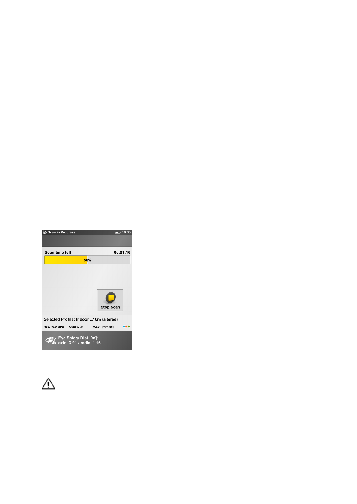
The scan process starts, the laser of the scanner willbe switched ON and the scanning view will be
displayed. The scanner's LEDs are blinking red as long as the laser of the scanner is switched ON.
During scanning, the scanner rotates clockwise by 180°. If you are scanning with color, the scanner
will continue to turn to 360° to take the pictures. The executed processing steps are displayed in the
status bar of the scanning screen, the scan progress is indicated by the progress bar.
To stop a scan touch the Stop Scan button in the scanning viewor press the Start / Stop button on
the scanner. You will then be asked to keep or delete the incomplete scan.
Caution – After having completed scanning and capturing the pictures, depending on environmental conditions,
the scanner may make another full turn to capture inclination data. It is important NOT to move the scanner
while it is capturing the inclination data. Else, the inclination data of the scan may be inaccurate and may not be
usable for the scan registration.
Trimble TX5 3D Laser Scanner User Guide 65
Page 66
4 Getting Started
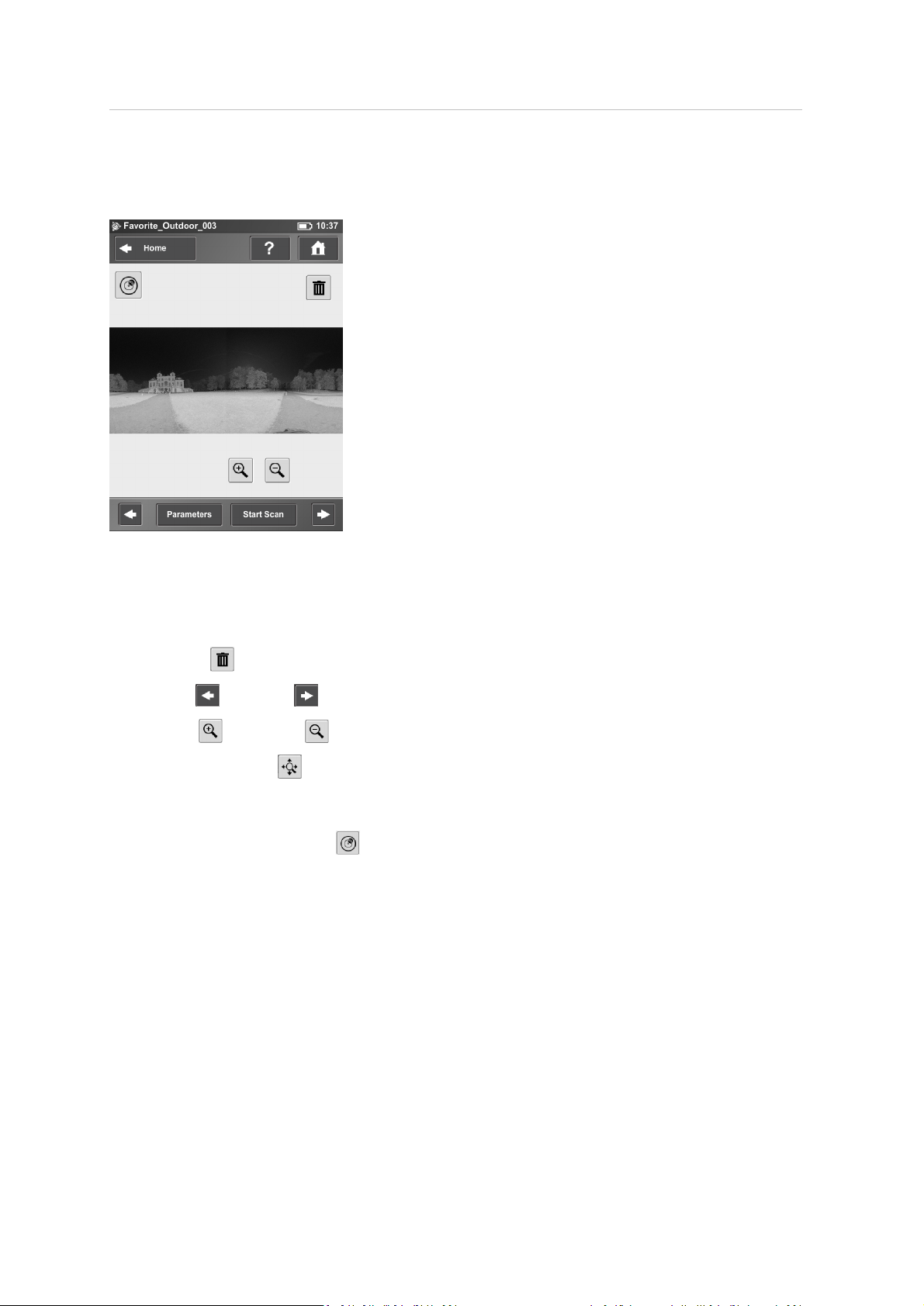
As soon as the entire scanning process is complete, the scanner plays a notification sound (ifnot
turned offin the settings) and a new screen appears with a previewpicture of the captured scan.
Now, you may move the scanner to the next scan position and start a new scan.
The scan previewshows a grayscalepicture of the captured scan to verify the scan itselfand to
check if allobjects (e.g. targets) are clearly visible. This preview does not show color.
Parameters button – Change the scanning parameters for the next scans.
Start Scan button – Starts the next scan.
Delete button – deletes the viewed scan file.
Use the Left and Right arrow buttons to browse through already captured scans.
Use the Plus and Minus buttons to zoom in or out.
The Reset Zoom button is only visible when you zoom into the scan picture. With this button
the scan picture can be zoomed back to its original size. When zoomed in you can move the
zoomed picture by dragging it with your fingers in any direction.
The Inclination Warning button is only visiblewhen the current inclination of the scanner is
above 5°. To get reliablemeasurements from the built-in dual axis compensator you should set up
the scanner with an inclination less than 5° before starting your next scan. For this, you may use
either a bubble inclinometer at the tripod or the inclinometer screen. Click this button to get to the
inclinometer screen. For more information, see Inclinometer (Dual Axis Compensator), page 101.
Trimble TX5 3D Laser Scanner User Guide 66
Page 67

4 Getting Started
Shutting down the laser scanner
To shut down the laser scanner, shortly press the Power button or use the shutdown button in the
operating software under Manage. AllLEDs will start blinking yellow. As soon as the laser scanner
has finished the shutdown process the LEDs will stop blinking and you can safely remove the battery
and the power supply.
DO NOT turn off the power of the laser scanner beforethe shut down cycle is complete. The laser
scanner has a PC with an integrated hard drive. This internal PC must be shut down before turning
off the power supply. If the power supply is disconnected or switched off without the laser scanner
being previously shut down, it may damage the internal PC and might lead to a loss of data.
Pressing and holding the button more than 10 seconds will switch the laser scanner off without
shutting down. Only ifthe laser scanner does not shut down normally because of a malfunction.
Note – If the laser scanner has not been shut down properly, the next boot process could take
more time than usual as the laser scanner checks the hard disk for errors. Some settings, which
were made shortly before shutting down the laser scanner, might also be lost.
Trimble TX5 3D Laser Scanner User Guide 67
Page 68
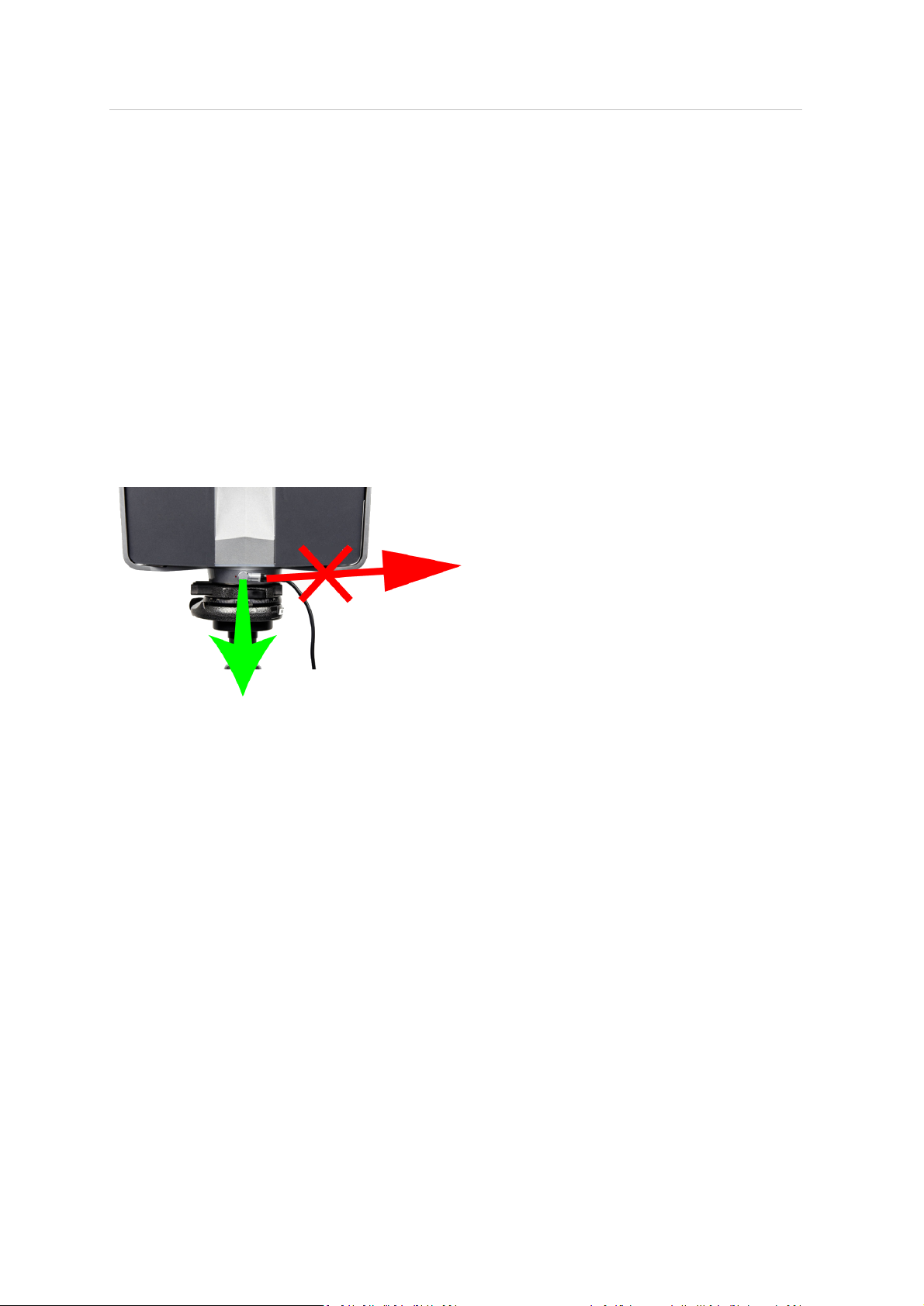
4 Getting Started
Powering off the laser scanner
Once the laser scanner has been completely shut down, disconnect the AC power cable first, then
disconnect the power supply cable from the laser scanner, remove the battery and secure the
equipment in protective cases.
Removing the battery
1. Open the battery cover.
2. Push the fastener to release the battery.
3. Remove the battery.
4. Close the battery cover.
Unplugging the power supply
Take care to unplug the bend connector from the laser scanner by pulling at the connector only! Do
not pull at the cable or you may damage the connector and the laser scanner!
Trimble TX5 3D Laser Scanner User Guide 68
Page 69

C H A P T E R
5
5TX5 Controller Software
In this chapter:
n
Generalelements
n
Home screen
n
Manage screen
n
View scans
n
Online help
This chapter provides information about the
TX5 Controller software, used to operate the
laser scanner.
Trimble TX5 3D Laser Scanner User Guide 69
Page 70
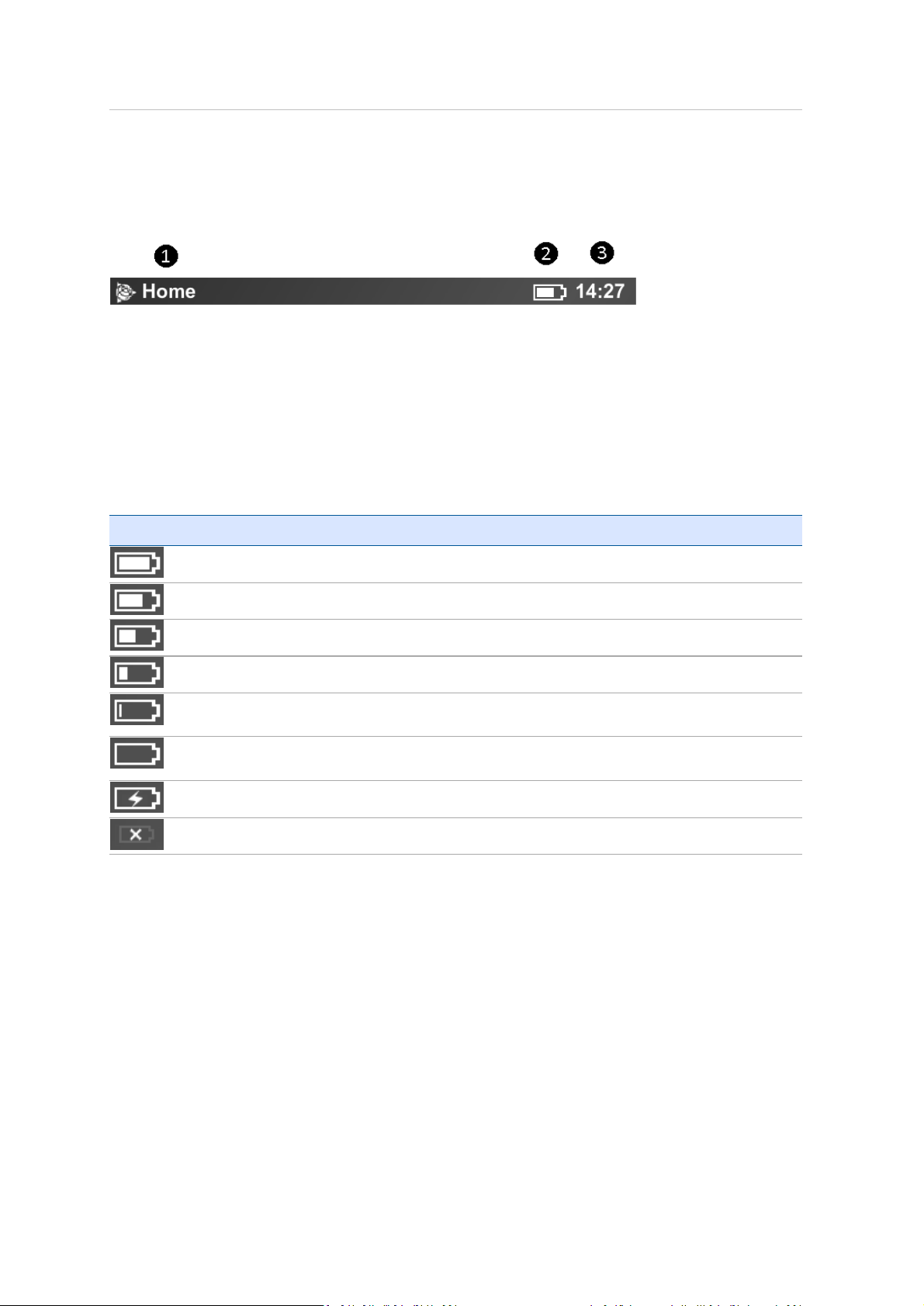
5 TX5 Controller Software
General elements
Status bar
Current view– The name of the currently active and visible screen on the
❶
display.
Battery icon – shows the status and charge state of the internal battery.
❷
Clock – shows the current time of the laser scanner. See
❸
time, page 44
scanner.
Symbols used for the battery status are:
Icon Meaning
for information on how to change the date and time of the
Setting the date and
Battery is fully charged
Charge state between 75 and 100%
Charge state between 50 and 75%
Charge state between 25 and 50%
Charge state between 10%and 25 percent. You should recharge the battery or connect the
power supply.
Battery is almost empty; the laser scanner willautomatically shut down within the next
minutes.
Battery is charging.
No battery in the laser scanner.
The exact charge state of the battery can be viewed under Manage / General Settings / Power
Management (see Power Management, page 88).
If the charge state of the battery is below 25percent you willget a warning. In this case use a spare
battery and/or connect the power supply to the laser scanner. If the charge state of the battery
reaches 10percent the laser scanner will stop scanning and will automatically shut down.
Trimble TX5 3D Laser Scanner User Guide 70
Page 71
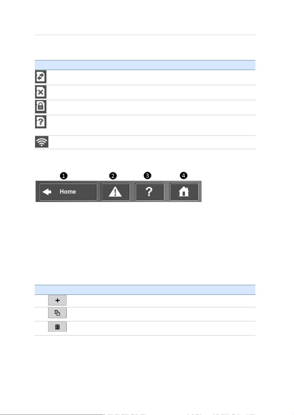
5 TX5 Controller Software
Further situational icons of the status bar:
Icon Meaning
SD Card is busy. Do not remove the card from the scanner whileit is busy, otherwise you
risk corrupting the data on the card.
No SD card inserted.
SD card is write protected. Remove writeprotection to be able to scan.
Unknown SD card inserted. The card cannot be read. This might be due to the SD card
being formatted in an unsupported filesystem.Format the SD card with the built-in format
function. For more information, see
WLANis turned on.
Navigation bar
SD Card, page 95
.
Back
❶
❷
button – returns you to the previous screen.
Errors and Warnings
button – this button only appears if warning or errors
are present. Pressing the button opens a screen that informs about details of
the existent warnings or errors. See
Help
❸
button – opens the online help of the currently active screen and
provides access to the laser scanner video guide. See
Home
❹
button – returns you to the
Errors and Warnings, page 94
Online help, page 108
Home
screen. See
Home screen, page 74
Frequently used buttons
Icon Meaning
Add
button. Adds new scan profiles, projects or operators.
Duplicate
the selected list element.
Delete
operators.
button. Adds new scan profiles, projects or operators by duplicating
button. Deletes selected list elements, like projects, scan profiles or
.
.
.
Trimble TX5 3D Laser Scanner User Guide 71
Page 72
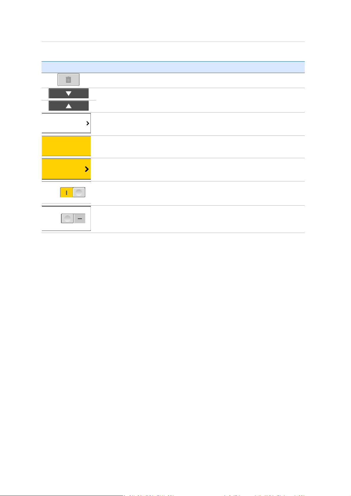
5 TX5 Controller Software
Icon Meaning
Disabled
Delete
button. The selected list element can not be deleted.
Scroll up and down buttons. Appear on the bottom of the screen if the content
of a screen exceeds the screen height. Press the button to scroll the screen up
or down.
An arrow on a list item indicates that you tap it to open a new screen with
further details or settings.
A highlighted field indicates that the list item is currently selected and active.
Highlighted list items indicate that the item is currently selected and that
further details and settings are available by tapping the list item once again
Check box. Used to turn functions on or off. Here, the function is turned on
Check box. Used to turn functions on or off. Here, the function is turned off.
Trimble TX5 3D Laser Scanner User Guide 72
Page 73
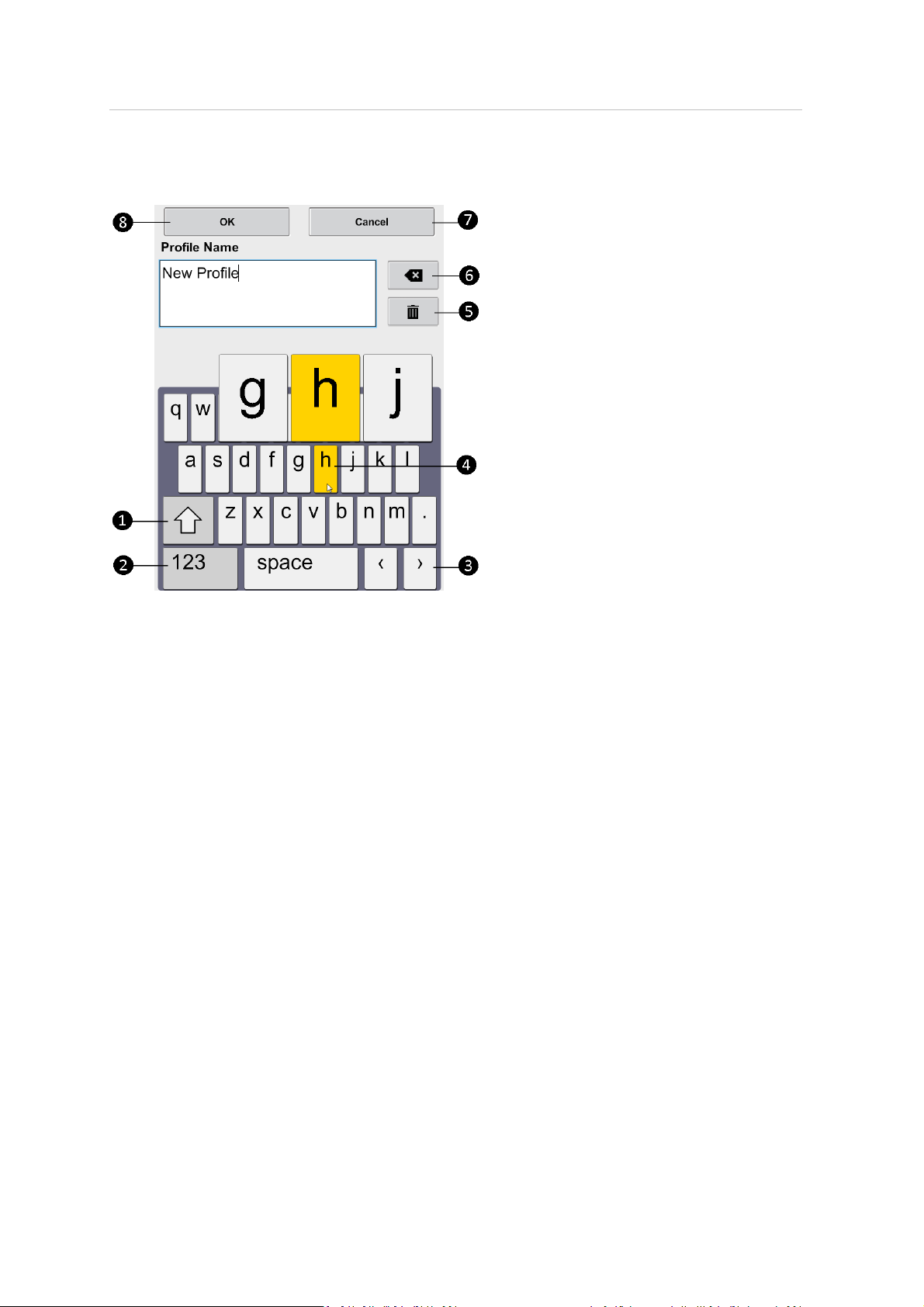
5 TX5 Controller Software
Onscreen keyboard
Shift key to toggle between capital and lower case letters.
❶
Key to toggle keyboard between standard and special characters.
❷
Moves the cursor in the text field right or left.
❸
Tap a key to enlarge it and its neighboring keys. Choose between the enlarged
❹
keys by dragging the finger a bit to the right or to the left. The selected key is
highlighted.
Delete key – deletes the complete text.
❺
Backspace
❻
❼
Cancel
button – returns to the previous screen without applying your
changes.
OK
❽
button – applies your input and returns to the previous screen.
Trimble TX5 3D Laser Scanner User Guide 73
Page 74
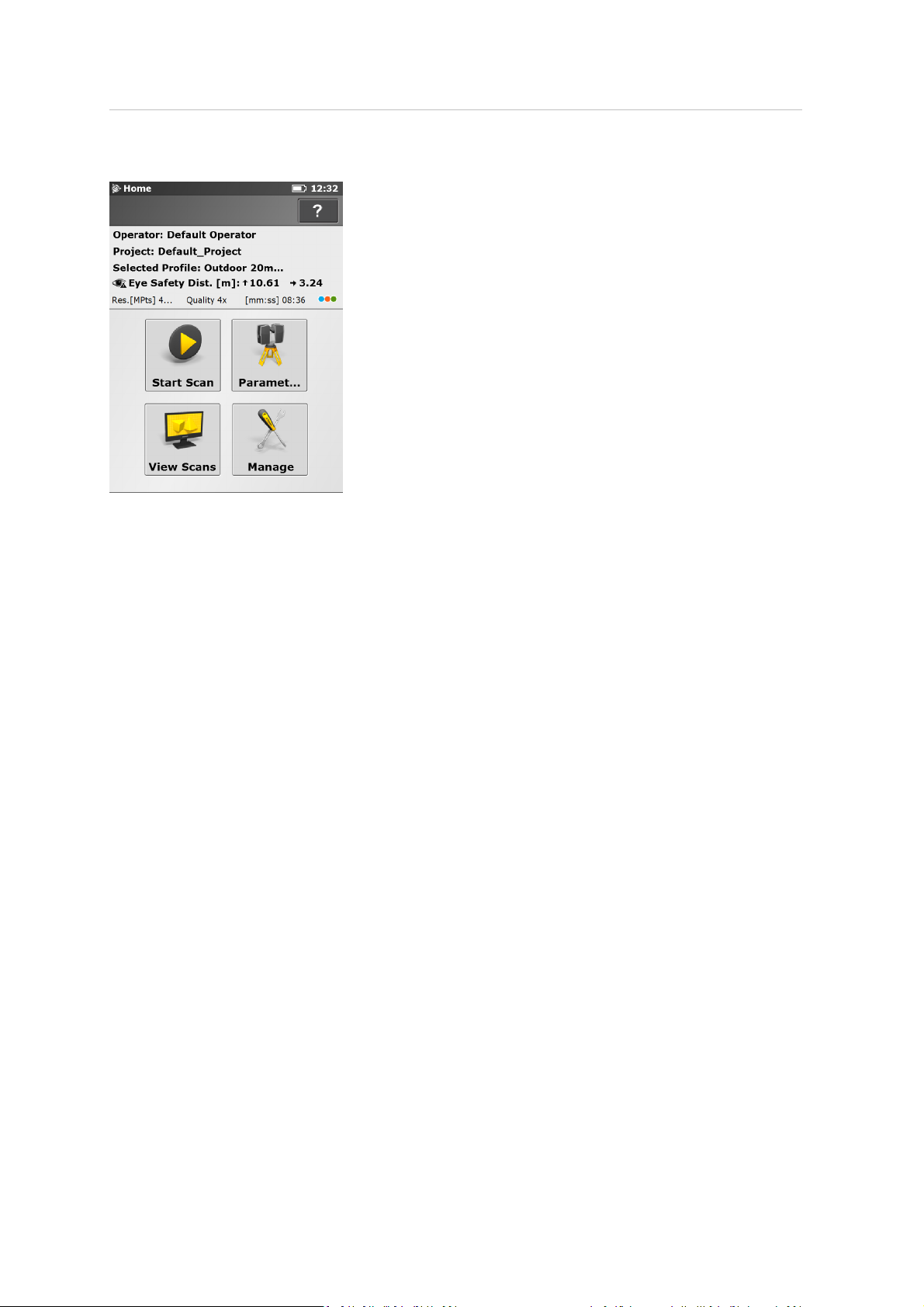
5 TX5 Controller Software
Home screen
Start Scan
Parameters
current scanning parameters. See
View Scans
scans, page 105
Manage
Manage screen, page 75
The information box shows the currently selected operator, project and scan
profile, as well as information about the current scanning parameters (resolution in
mega points, quality, scan duration and color) and the corresponding axial and
radial eye safety distance.
button – Starts a scan. See
button – Opens the dialog to select another scan profile and to edit the
button – Preview the scans that are stored on the SD card. See
.
button – Manage scan profiles, projects, operators and the scanner. See
.
Starting a scan, page 65
Setting the scan parameters, page 49
.
.
View
Trimble TX5 3D Laser Scanner User Guide 74
Page 75
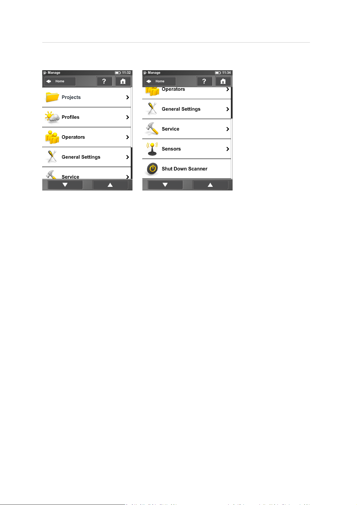
5 TX5 Controller Software
Manage screen
Projects – Select the current scan project, add new or edit existing projects (see Managing scan
projects, page 76). Tap to get a list of all available projects.
Profiles – Select the current scan profile, create new or edit existing scan profiles. See Managing scan
profiles, page 80.
Operators – Select the current scanner operator, create new or edit existing operators. See
Managing operators, page 83.
General Settings – Opens the menu of the general scanner settings. See General settings, page 86.
Service – Opens the menu for scanner services, like firmware updates, backups or viewing errors
and warnings. See Service, page 93.
Sensors – Opens the menu for the scanner sensors administration. See Sensors, page 100.
Shut down Scanner – Tap to shut down the scanner. See Shutting down the laser scanner, page 67.
Trimble TX5 3D Laser Scanner User Guide 75
Page 76
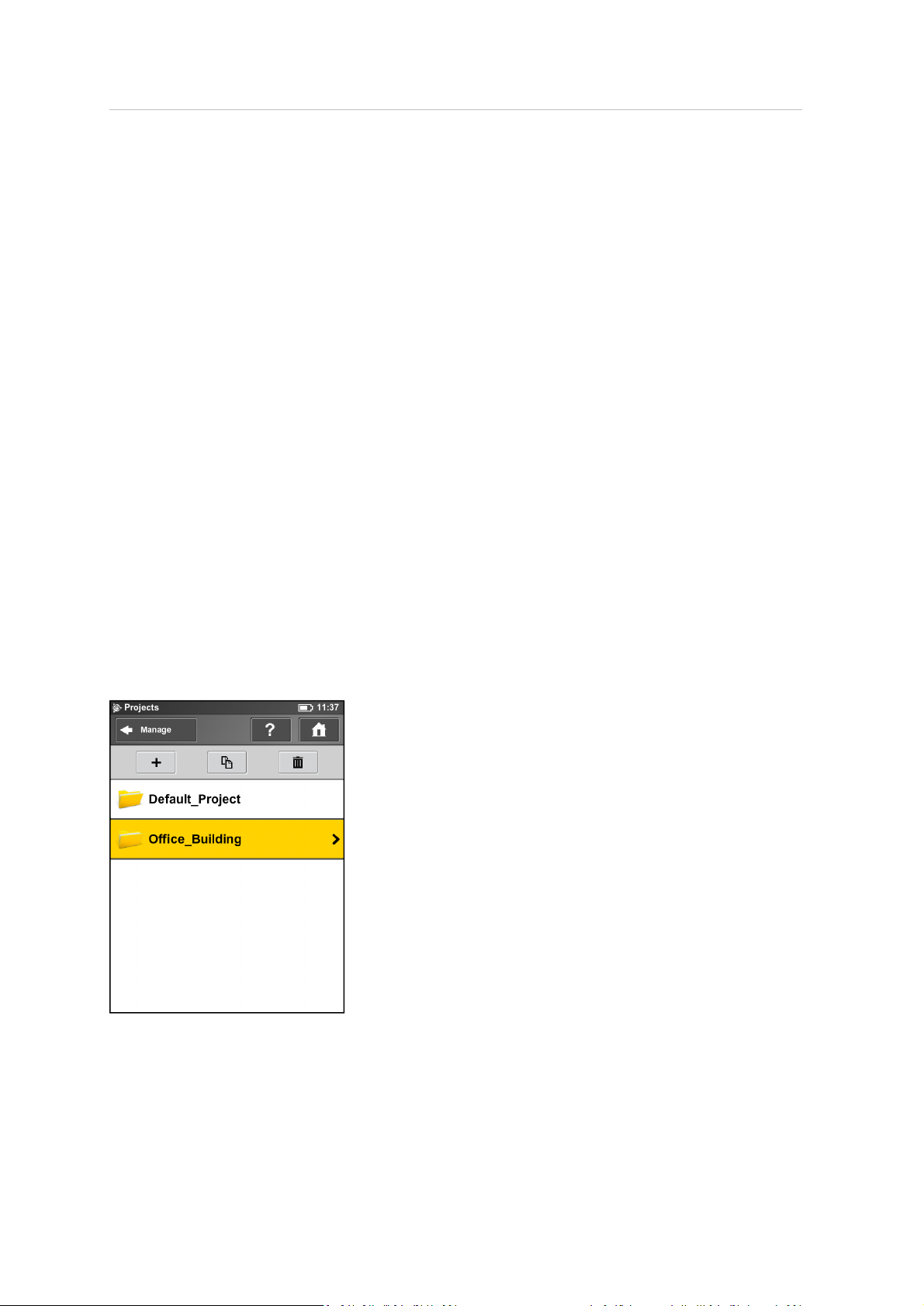
5 TX5 Controller Software
Managing scan projects
Projects in the operating software represent the structure of your real scan projects. A scan project
usually consists of a main project that has several subprojects. For example, if you are scanning a
multi-level building, each floor of this building might represent one subproject and each of these
floors or subprojects might have further subprojects, for example rooms.
Before carrying out a scan project you should map its structure to the scanner‘s operating software.
You can reproduce the complete structure of your scan project within the operating software of the
scanner or, more convenient, with TX5 SCENEsoftwareand then transfer the project to the scanner
via the SD card. For more information, refer to the Trimble TX5 SCENESoftware User Guide.
Before starting a scan, you should select a scan project from the projects list that has been prepared
by you in advance. This project should correspond to the current scan position. The next scan is
then assigned to this project. This information will be attached to each scan, which is very helpfulfor
the later registration of the scans and is used to automatically combine the scans to scan clusters.
Note – Every project and subproject gets a unique internal identification number when it is
created. Combining the scans to scan clusters during postprocessing in TX5 SCENE software is done
according to this identification number and not on the basis of the project name. This is
particularly relevant when working with several scanners on the same scan project. In this case
you should create the project (structure) once as a master and transfer it to all of your scanners.
Avoid creating or editing a project of the same scan project separately on every scanner, because
even if the separately created projects and subprojects are given the same name, they will have
different identification numbers and will be treated as different projects by the TX5 SCENE software.
Creating a scan project
This view shows a list of all available scan projects.
The "Default Project" is a standard project that may be selected when working in no particular scan
project. The "Default Project" cannot be deleted and you cannot change its name or parent project.
Trimble TX5 3D Laser Scanner User Guide 76
Page 77
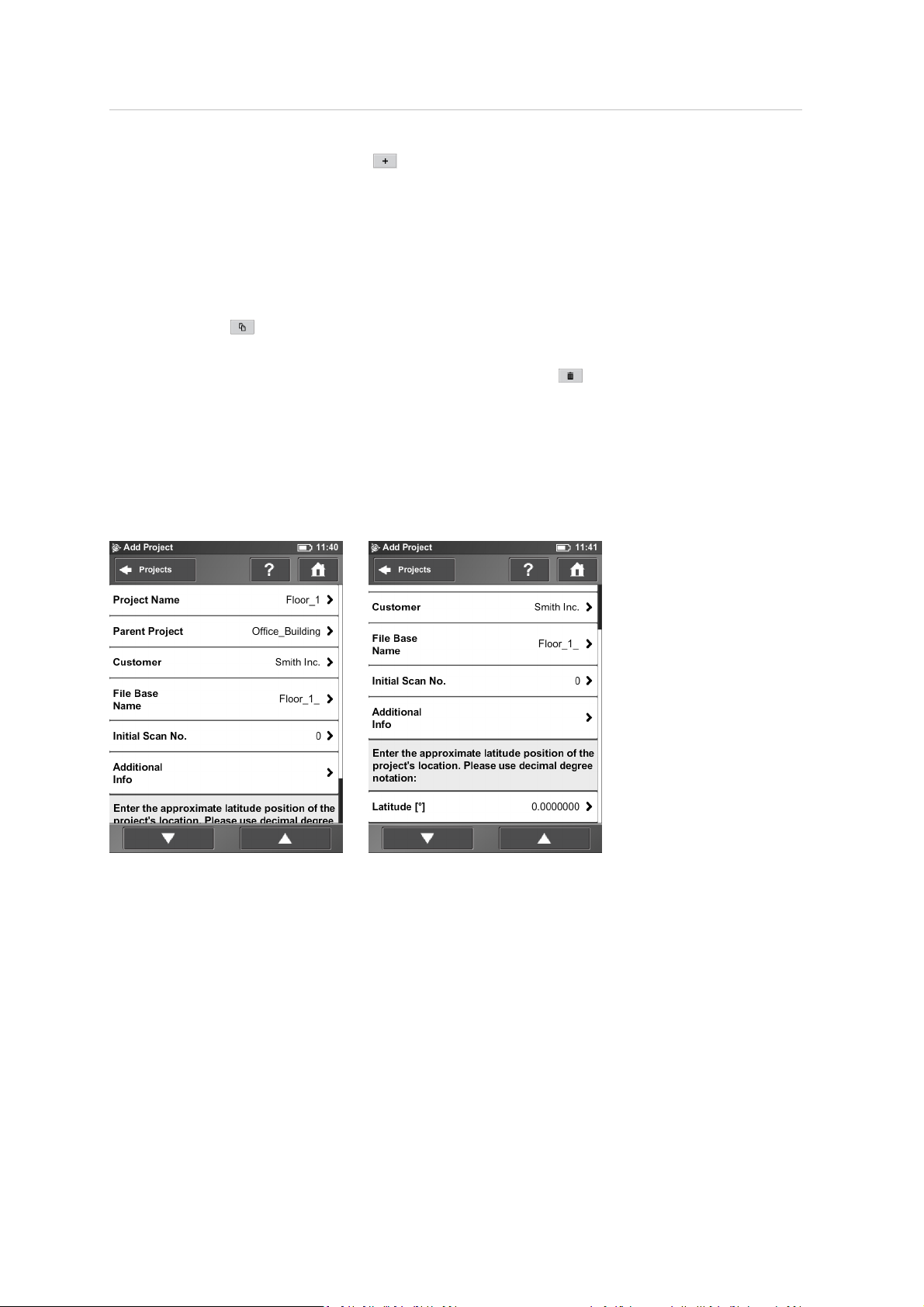
5 TX5 Controller Software
To add a project, click the Add button . A new subproject is added to the selected project and
the View Project screen appears. Here, you can change the name and enter further details of the
new project. If you want the newproject to be a main project without any parent projects, change
its parent project to no parent project (see below for details) or you have to select the Default
Project before adding the newproject. With the Default Project selected, new projects are always
added as a main project without parent projects.
Instead of adding a completely new project or subproject, you can also create new projects by
duplicating existing ones. For this, select the project that you want to duplicate and click the
Duplicate button . The newly created project has the same settings and properties as the original
project.
To delete a project, select it in the list and click the Delete button . If the project has subprojects,
they are also deleted.
Projects are stored on the SD card. If you remove the SD card from the scanner, the entirestructure
of the currently selected project (all of its parent projects and their sub projects) as wellas the
Default Project remain on the scanner. All other projects are removed from the list, but remain on
the SD card. If you insert a new SD card, the selected project, its parent and sub projects that are on
the scanner are saved to the new SD card as soon as you make changes to it or as soon as a scan is
started. If the new SD Card contains projects, they are added to the projects list.
Project Name – The name of the project. Tap to change the name.
Parent Project – The parent project of the displayed project. No Parent Project means that the
current project is a main project and not a subproject. Tap to change the parent project. A new
screen appears with a list of allavailable parent projects. Tap a project to select it. The selected
parent project is highlighted. The currently edited project becomes subproject of this project.
Trimble TX5 3D Laser Scanner User Guide 77
Page 78
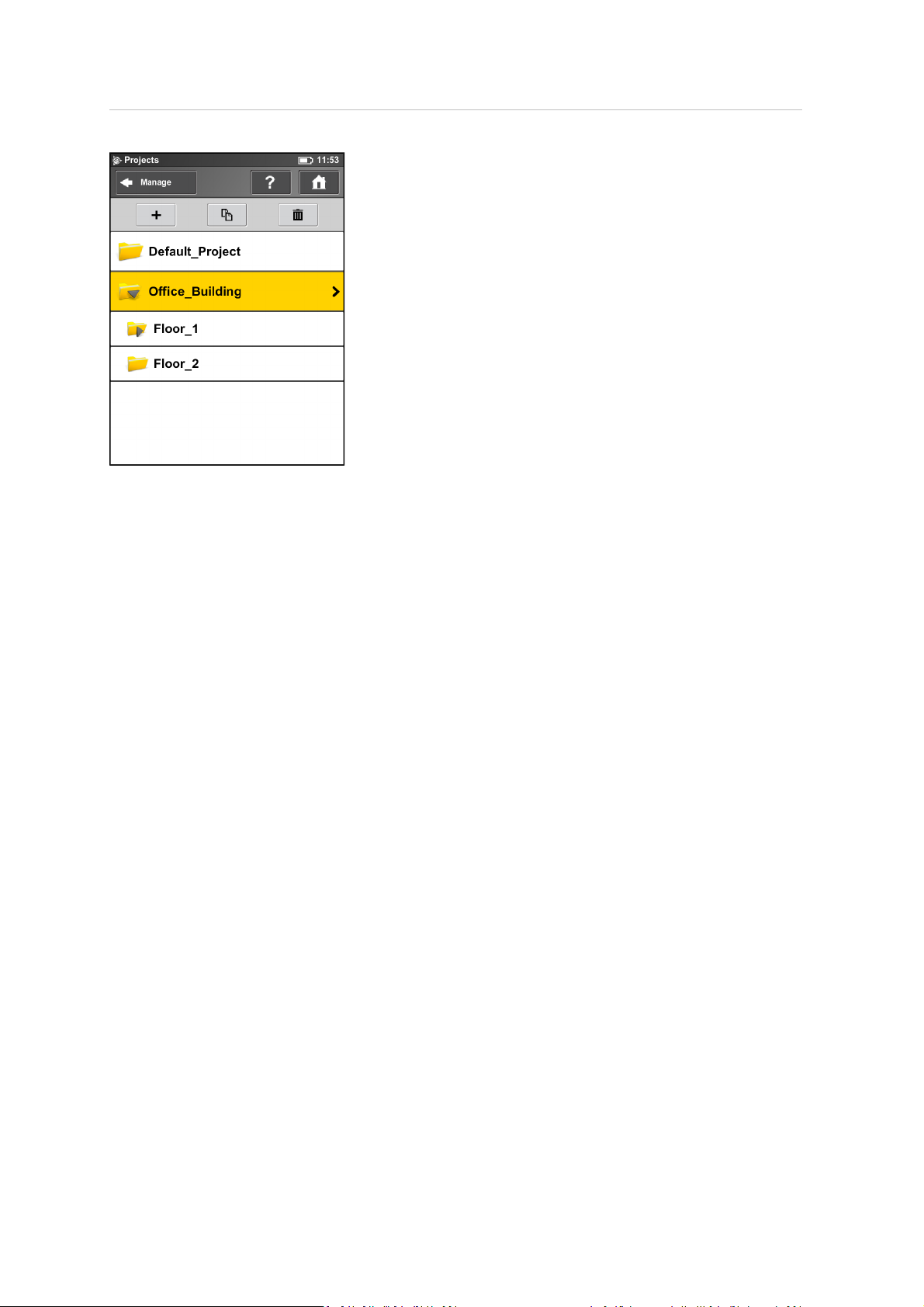
5 TX5 Controller Software
Customer – If you are carrying out the scan project by order of a company, you can enter its name
here.
File Base Name – The scan will be saved with a file name consisting of this base name followed by
the current scan number.
Initial Scan No. – Automatically increments with each successive scan. Can be reset and may be
used to indicate the number of scans per scan session.
Additional Info – Additional project information.
Latitude [°] – If known, enter the approximate (+/- 10° is sufficient) latitude position of the scan
project here. This information helps to improve the calibration of the inclination sensor and leads to
more precise inclination data and thus to better scan registration results. Enter the latitude value in
decimal degreenotation.
Editing a scan project
To edit a scan project, select it in the list and tap it once again to viewthe details screen.
Trimble TX5 3D Laser Scanner User Guide 78
Page 79
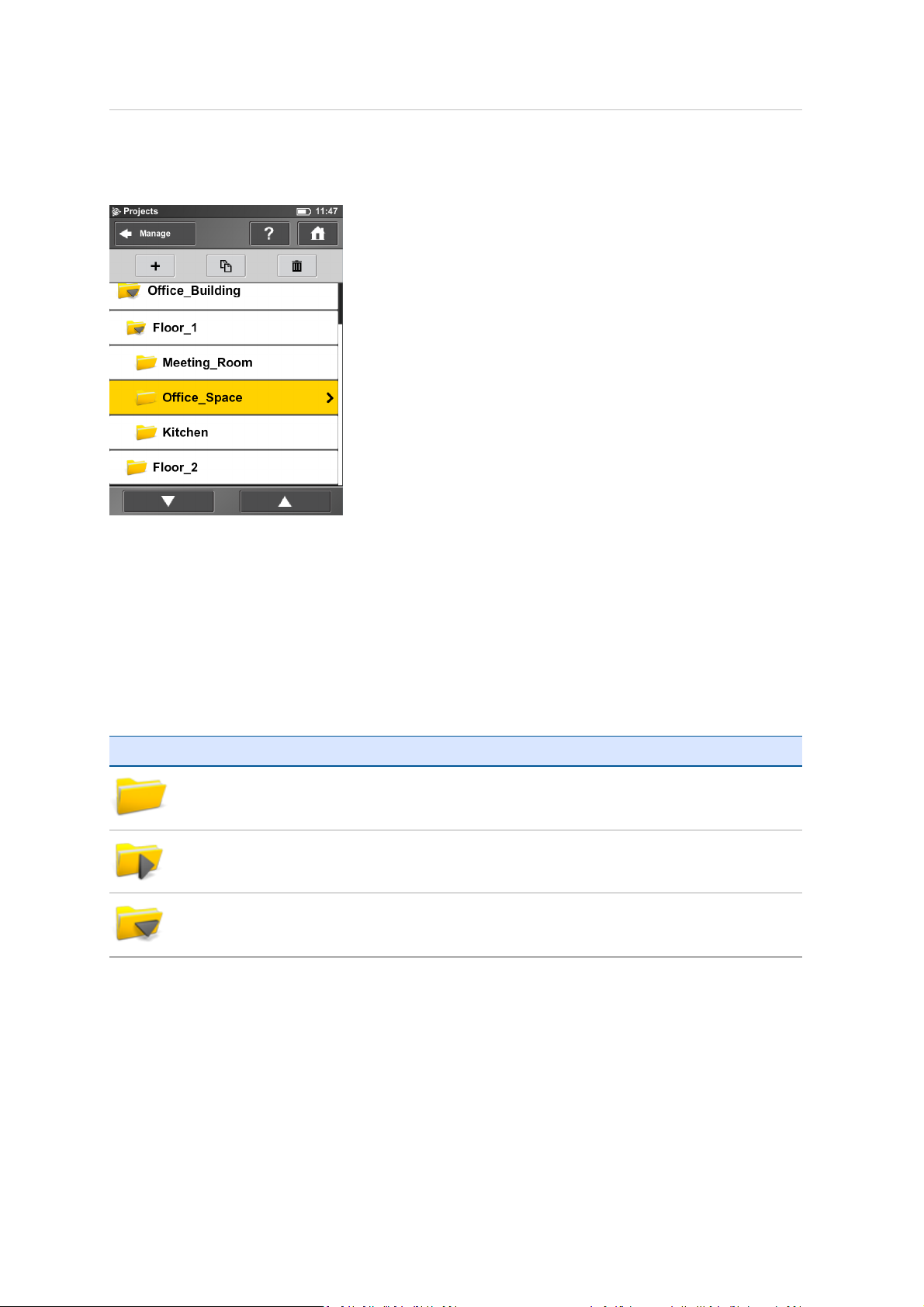
5 TX5 Controller Software
Selecting a scan project
The project list contains the currently selected project and allfurther projects stored on the SD card.
To select a project, tap it in the list. The selected project is highlighted. To view or change details of
the selected project, tap it again.
To display available subprojects of a project, select it and the list will be expanded with its sub
projects. Proceed accordingly with further subprojects.
If the list of projects exceeds the screen size, scroll the list up or down with the buttons on the
bottom.
The icons on the projects are described below:
Icon Description
Project has no subprojects.
Project has sub projects. Click to expand the list to view the sub projects.
Project has sub projects. Its sub projects are currently shown (list is expanded accordingly).
Trimble TX5 3D Laser Scanner User Guide 79
Page 80
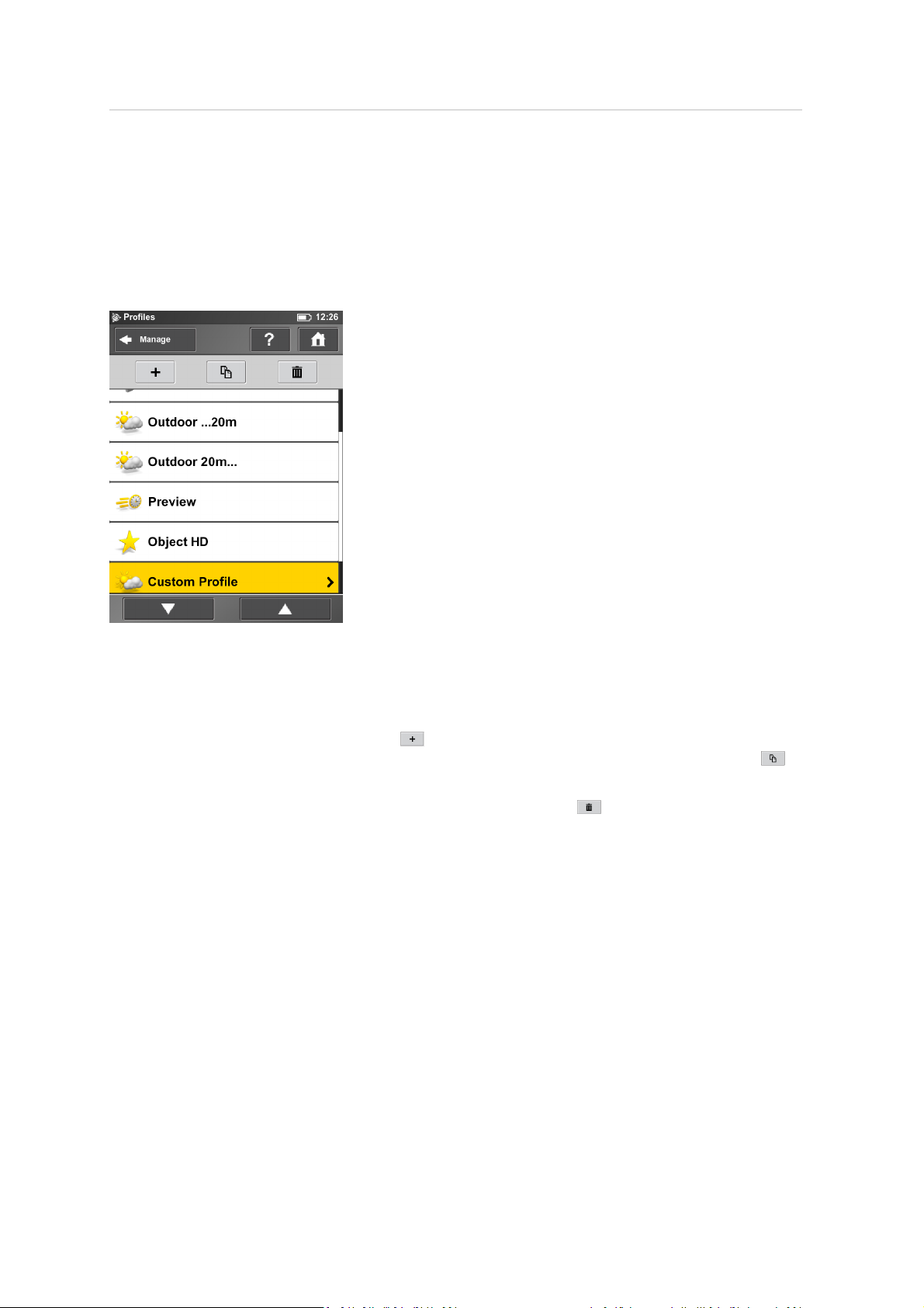
5 TX5 Controller Software
Managing scan profiles
Selecting scan profiles to use theirparameters for the next scan is described in Setting the scan
parameters (page 49). This topic describes how to add new and how to edit existing scan profiles.
Creating a scan profile
The laser scanner comes with predefined scan profiles. See Factory predefined scan profiles, page
82. These scan profiles are read-only and cannot be changed or deleted. But you can add and
manage your own custom scan profiles.
This view shows all scan profiles that are availableon the scanner.
To add a new profile, click the Add button . You can also add new profiles by duplicating existing
profiles. To do this, select the profile that you want to duplicate and click the Duplicatebutton . A
new screen appears to enter the profile name and to adjust its scan parameters.
To delete a custom scan profile, select it and click the Delete button . You cannot delete
predefined profiles.
Trimble TX5 3D Laser Scanner User Guide 80
Page 81
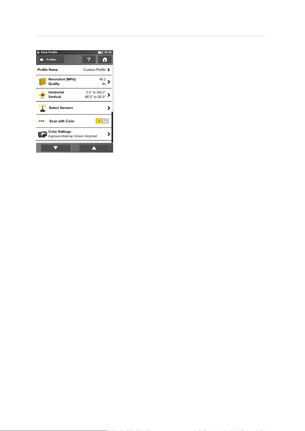
5 TX5 Controller Software
Profile Name – Name of the scan profile. Tap to change it.
The further settings here are similar to the settings of the scanning parameters. For more
information, see Setting the scan parameters, page 49.
Editing a scan profile
To edit a scan profile, select it in the list and tap it again to viewits details. You cannot edit
predefined profiles.
Trimble TX5 3D Laser Scanner User Guide 81
Page 82

5 TX5 Controller Software
Factory predefined scan profiles
The following table provides an overviewof the available factory predefined scan profiles:
Indoor …10m Indoor 10m… Outdoor …20m Outdoor 20m… Preview Object HD
Description
Resolution
Quality
Vertical area
Horz. area
Inclinometer
Compass
Altimeter
Color
Exposure
Metering
Mode
Clear Contour
Clear Sky
Point Distance
(mm/10 m)
NOHD (axial /
radial) (m)
The following values refer to full area scans (360° horizontally / 300° vertically):
Resolution
(MPts)
Net Scan
Duration
(hh:mm:ss)
Scan File Size
(MB)
Scan Size (pt)
Scan indoors
where the
distancesfrom
the scanner to
the main objects
of interests are
less than 10m.
1/8 1/5 1/5 1/4 1/16 1/2
3x 4x 4x 4x 4x 6x
-60° to 90° -60° to 90° -60° to 90° -60° to 90° -60° to 90° -60° to 90°
0° to 360° 0° to 360° 0° to 360° 0° to 360° 0° to 360° 0° to 360°
ON ON ON ON ON ON
ON ON ON ON ON ON
ON ON ON ON ON ON
ON ON ON ON OFF ON
Horizon Weighted Horizon Weighted Horizon Weighted Horizon Weighted Horizon Weighted Horizon Weighted
ON ON ON ON ON ON
ON ON ON ON ON ON
12.272 7.670 7.670 6.136 24.544 3.068
4.50/ 1.40 10.60/ 3.30 10.60 / 3.30 12.50/ 4.20 4.50 / 0.90 29.40/ 16.20
11 28.2 28.2 44 2.8 176.0
00:02:57 00:06:38 00:06:38 00:09:12 00:00:57 01:56:00
68.90 122.08 122.08 171.18 8.53 2216.66
5156x 2134 8248x 3414 8248x 3414 10310x 4268 2578x 1067 20622x 8534
Scan indoors where
the distances from
the scanner to the
main objects of
interests are
greater than 10m.
Scan outdoors
where the
distancesfrom the
scanner to the
main objects of
interests areless
than 20m.
Scan outdoors
where the
distancesfrom the
scanner to the
main objects of
interests are
greater than 20m.
Capture afast and
rough preview scan
of the environment
in low resolution.
Scan certain
objects or areasin
very high
resolution. Limit
the scan areato
the object or area
of interest, else
the scan might
take very long to
complete.
Trimble TX5 3D Laser Scanner User Guide 82
Page 83
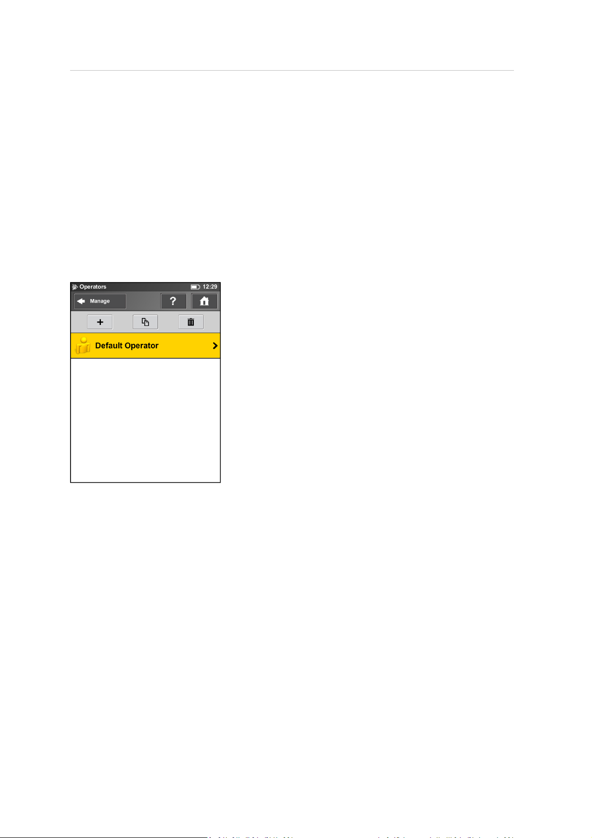
5 TX5 Controller Software
Managing operators
The information about which scanner operator has recorded which scans, can be useful for the
person who is postprocessing the scans, especially when there areseveralscanner operators
working on the same scan project.
You are able to assign scanner operators to the captured scans. To do this, select the operator in
the operators list. You might have to create the operator first ifit does not already exist. The name
of the selected operator willthen be stored in the metadata of the next scans and can be accessed in
the TX5 SCENE software during scan postprocessing.
Creating an operator
Trimble TX5 3D Laser Scanner User Guide 83
Page 84
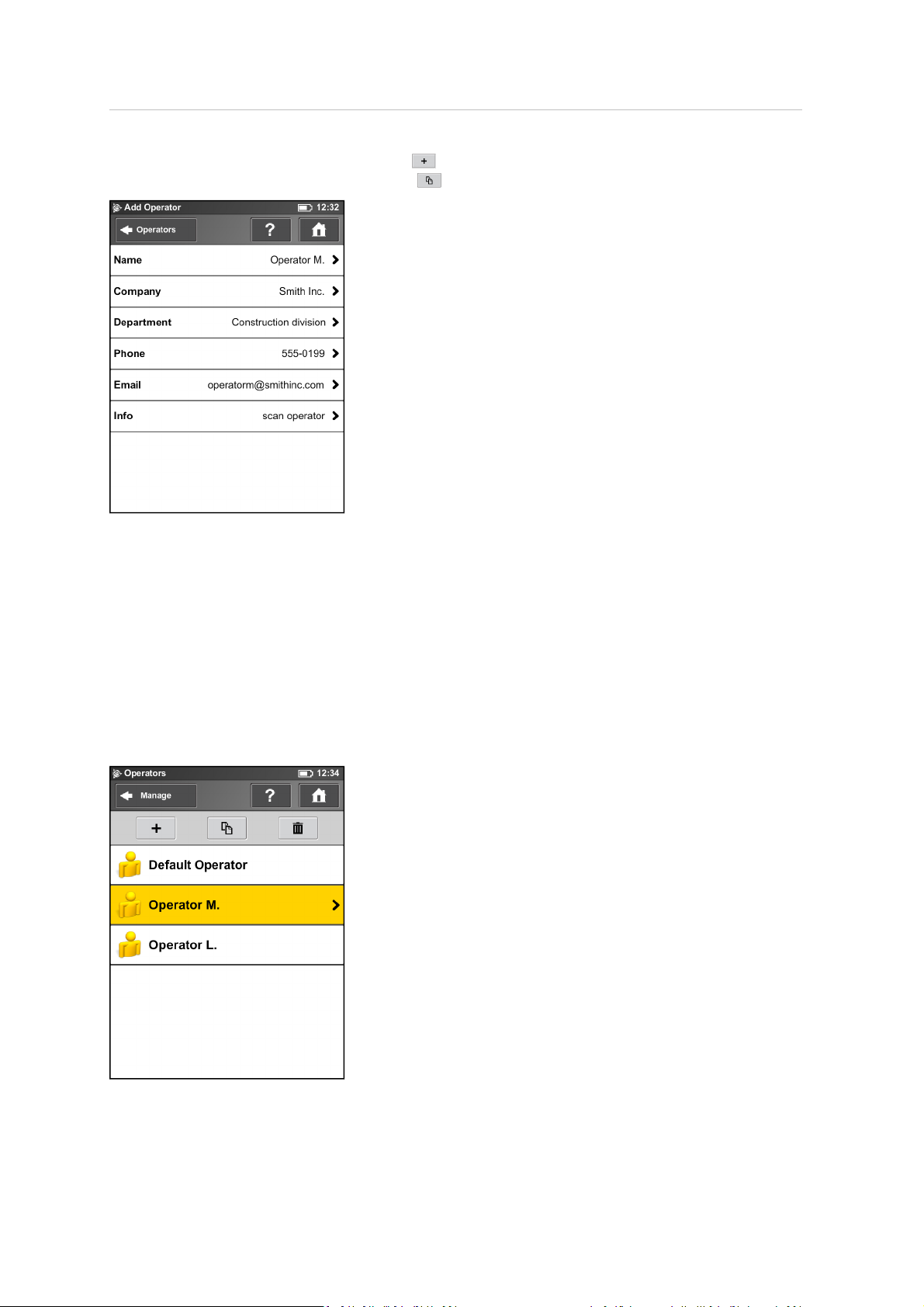
5 TX5 Controller Software
To add a new operator, tap the Add button . Alternatively, tap an operator you want to
duplicate and then tap the Duplicate button . The details screen for the newoperator appears:
Name – The name of the scanner operator.
Company – The name of the company providing the scanning service.
Department – The department the operator works for.
Phone – The operator's phone number.
Email – The operator's email address.
Info – Any additional information required by the service provider. This may be shift leaders, project
managers etc.
Selecting an operator
Trimble TX5 3D Laser Scanner User Guide 84
Page 85

5 TX5 Controller Software
To select an operator, tap it in the list. The selected operator is assigned the next captured scans
until another operator is selected. To viewor edit details of the selected operator, tap it again.
To delete an operator, tap it and then tap the Delete button .
Trimble TX5 3D Laser Scanner User Guide 85
Page 86
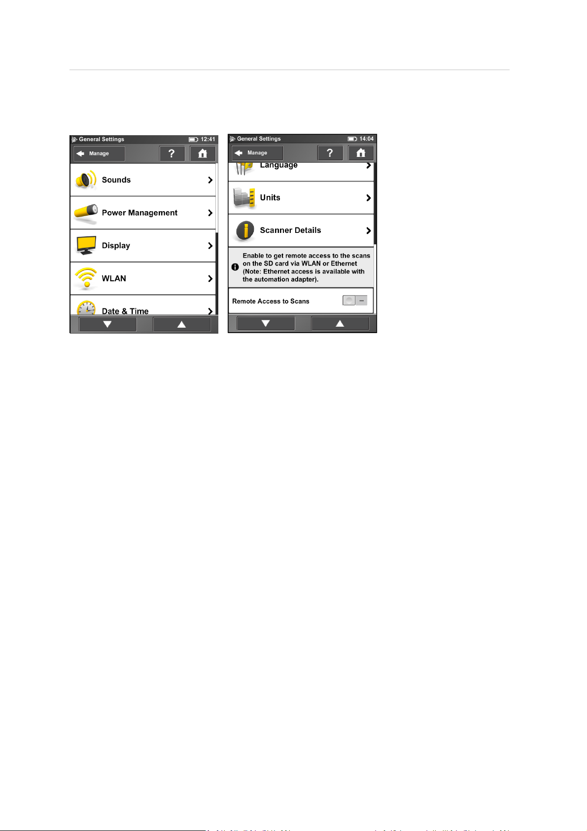
5 TX5 Controller Software
General settings
Sounds – Change the volume of the scanner sounds, enable or disable scanner sounds. See Sounds,
page 87.
Power Management – Set up the screen saver; view the detailed battery charge state, and enable
or disablestart on power which enables the scanner to be turned on by connecting the power
supply. See Power Management, page 88.
Display – Set the brightness of the screen, recalibrate it or change the wallpaper of the Home screen.
See Display, page 88.
Date & Time – Change the displayed time and date format and change the date and time of the
scanner. See Setting the date and time, page 44.
Language – Change the language of the operating software. See Setting the interface language,
page 44.
Units – Change the displayed unit of lengths. See Setting the unit of length and the temperature
scale, page 46.
WLAN – The laser scanner has an integrated WLANantenna that allows to remotely connect to the
scanner and to control it with an external device. Tap to view and change the WLANsettings and to
turn WLAN on or off. See WLAN/ Connecting to the scanner via WLAN, page 89.
Note – WLAN is only officially supported on scanners with the multi-sensor package.
Scanner Details – View and change details of the scanner. See Scanner Details, page 92.
Remote Access to Scans – Enabling this function allows access to the scans on the inserted SD card
from remote devices that are connected to the scanner via WLANor Ethernet. For more
information, see WLAN / Connecting to the scanner via WLAN, page 89.
Note – The status of the SD card is set to busy when this function is enabled. Disable this function
before you remove the SD card from the scanner. Remote access is automatically disabled when
shutting down the scanner. You must enable it again after rebooting the scanner.
Trimble TX5 3D Laser Scanner User Guide 86
Page 87
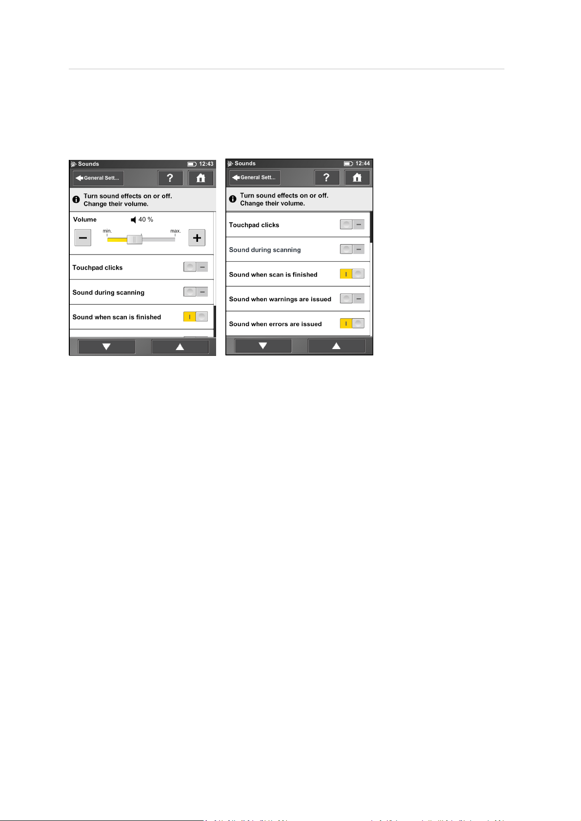
5 TX5 Controller Software
Sounds
The scanner has a built-in loudspeaker and some scanner events are signaled by sounds. You can
switch sounds on or offand change their volume.
Volume – Increase or decrease the volume of the scanner sounds.
Touch pad clicks – Switch on or switch off sound to confirm button clicks.
Sound during scanning – If switched on, the scanner gives a warning signal when the laser is
switched on and the scanner is scanning.
Sound when scan is finished – If switched on, the scanner sounds to confirm scan completion.
Sounds when warnings are issued – If switched on, the scanner sounds when a warning is issued.
Sounds when warnings are issued – If switched on, the scanner sounds when an error is issued.
Trimble TX5 3D Laser Scanner User Guide 87
Page 88
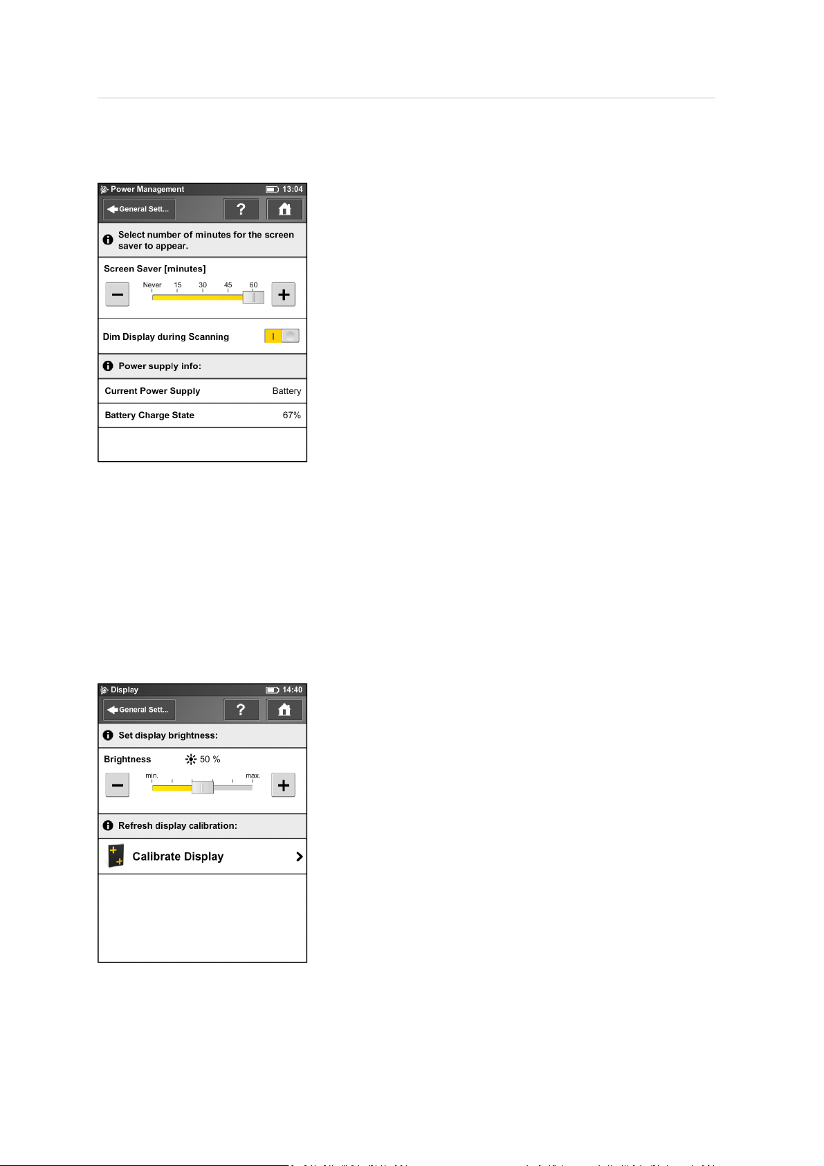
5 TX5 Controller Software
Power Management
Screensaver – If the screen has not been touched for a period of time, a screensaver appears.
Change the length of time before the screensaver appears bytapping the plus or minus buttons. To
deactivate the screensaver, set the time to "Never". When the screensaver is visible, touch the
screen to return it to operation mode.
Dim display during scanning – If switched on, the brightness of the screen decreases during
scanning to save battery power. Switching this option to ON is useful for long lasting scans.
Power supply info – Informs about the current power supply and the exact charge state of the
battery.
Display
Brightness – Set the brightness of the screen.
Trimble TX5 3D Laser Scanner User Guide 88
Page 89
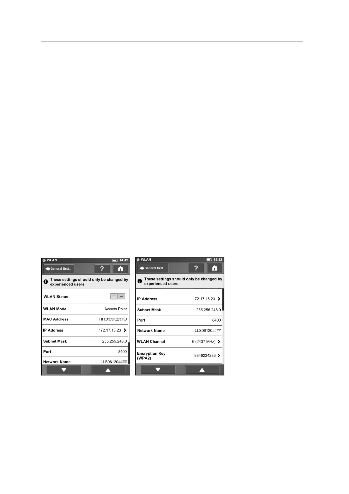
5 TX5 Controller Software
Calibrate the display – If you experiencethe touch screen to be slightly misaligned, you may have to
recalibrate it. Tap this button and followthe instructions on the appearing screen. We recommend
using a stylus to calibrate the display. If the calibration of the touch screen is corrupted so that it is
unusable, you should reset the calibration of the display to its factory settings. To do this, shut
down the scanner using the Power button. Wait untilthe scanner has shut down, then press and
hold down the Power button for at least five seconds until the LED on the sensor side of the scanner
illuminates yellow, then release the button again. The scanner then boots up and resets the
calibration of the touch screen to its factory settings.
Change the wallpaper – Change the wallpaper of the Home screen. Tap to get a list of available
wallpapers, which are stored on the scanner. To import new wallpapers to the scanner, use the
backup option.
Date and Time
See Setting the date and time, page 44.
Language
See Setting the interface language, page 44.
Units
See Setting the unit of length and the temperature scale, page 46.
WLAN / Connecting to the scanner via WLAN
The laser scanner has an integrated WLAN antenna that allows the scanner with to remotely
connect to portabledevices, like notebooks, PDAs or tablet computers. Once you have connected
your remote device to the scanner via WLAN, you are able to remotely access the scanner‘s
Trimble TX5 3D Laser Scanner User Guide 89
Page 90

5 TX5 Controller Software
operating software with a standard web browser. You can also remotely access the scan files on the
inserted SD card.
Note – To run the TX5 Controller software, the web browser must support Adobe Flash.
WLAN Status – Tap to turn WLANon or off. If WLANis not needed Trimble recommends turning it
off.
Note – Changes to WLAN settings are only possible if WLAN is turned off.
WLAN Mode – The scanner‘s WLANnetwork is configured as a wireless ad hoc network.
Note – Depending on the manufacturing date of the scanner, the WLAN might be configured as an
ad hoc network.
WLAN Mode – The scanner‘s WLANnetwork is configured as an access point.
IP address – The WLANIP address of the scanner. If your remote deviceis connected to the scanner,
enter this address into the address field of your web browser followed by port 8400 (e.g.
172.17.16.23:8400)to access the operating software. Tap to change the scanner‘s IP address.
Subnet mask – The subnet mask of the scanner‘s wireless network.
Port – The network port which is used for receiving requests from client hosts. When connecting to
the scanner using a web browser, enter the scanner‘s IP address followed by this port number into
the address field of the browser (seealso IP address).
Network name – The name of the wireless network. Usually it is the scanner‘s serial number. In the
list of wireless connections on your remote device, the TX5 3D laserscanner is listed with this name.
If the scanner is not listed, refresh the network list, after some seconds the remote device should
find the laser scanner and display it in the list.
WLAN channel – The channel used for the WLAN network. Tap to change it. If encountering
interference from other devices, consider changing the channel to avoid it.
Note – All WLAN devices on the network must use the same channel.
Encryption key – The scanner‘s WLAN network is encrypted with this key. The encryption key is a
WPA2 key. Enter this key on your remote device when prompted to establish the connection to the
scanner. If you want to change the encryption key, tap this field and enter your own key. The key
must consist of 10 to 63 arbitrary digits.
Configuring a notebook with Microsoft Windows software
To configure a notebook running a Microsoft®Windows® operating system:
1. Do one of the following:
ll
For the Windows XP operating system, right-click the wireless network icon in the taskbar
and select View Available Wireless Networks.
l
For the Windows 7 operating system, click the WLANicon in the taskbar.
A list with the availablewireless network connections appears, including the serialnumber of
the scanner.
Trimble TX5 3D Laser Scanner User Guide 90
Page 91
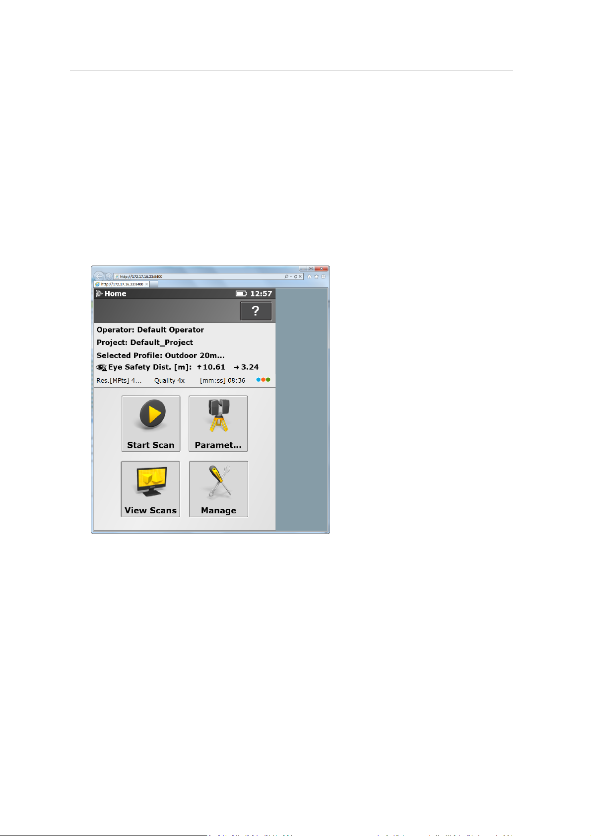
5 TX5 Controller Software
2. Select the wireless network showing the scanner's serial number scanner‘s WLAN network. For
Windows XP you must also click Connect.
3.
When prompted, enter the WLAN encryption key. As soon as the notebook is connected to the
scanner, open your web browser. In the address field of the web browser enter the WLANIP
address of the scanner followed by port 8400 (for example http.//172.17.16.23:8400).
Note – Adobe Flash Player must be installed on your system. Make sure that you do not use a
proxy server for the network connection. With some web browsers, such as Internet Explorer,
it might also be necessary to allow blocked content before you can run the operating
software.
The Home screen of the operating softwareappears in your web browser and you can control
the scanner as usual.
Remotely accessing the scans on the SD card
To access scan files stored on the scanner‘s removable SD card from a connected remote device,
enable the Remote Access to Scans option in the Manage / General Settings screen of the TX5
Controller software first. Then open Windows Exploreron the remote device and enter the following
address into the address bar: \\WLAN_IP_ADDRESS_O F_SCANNER\Scans (for example
\\172.17.16.23\Scans). You should have access to the scans now and can download them to the
remote device.
Note – Copying the files from the scanner via WLAN may take a while, depending on connection
speed and signal strength.
Trimble TX5 3D Laser Scanner User Guide 91
Page 92
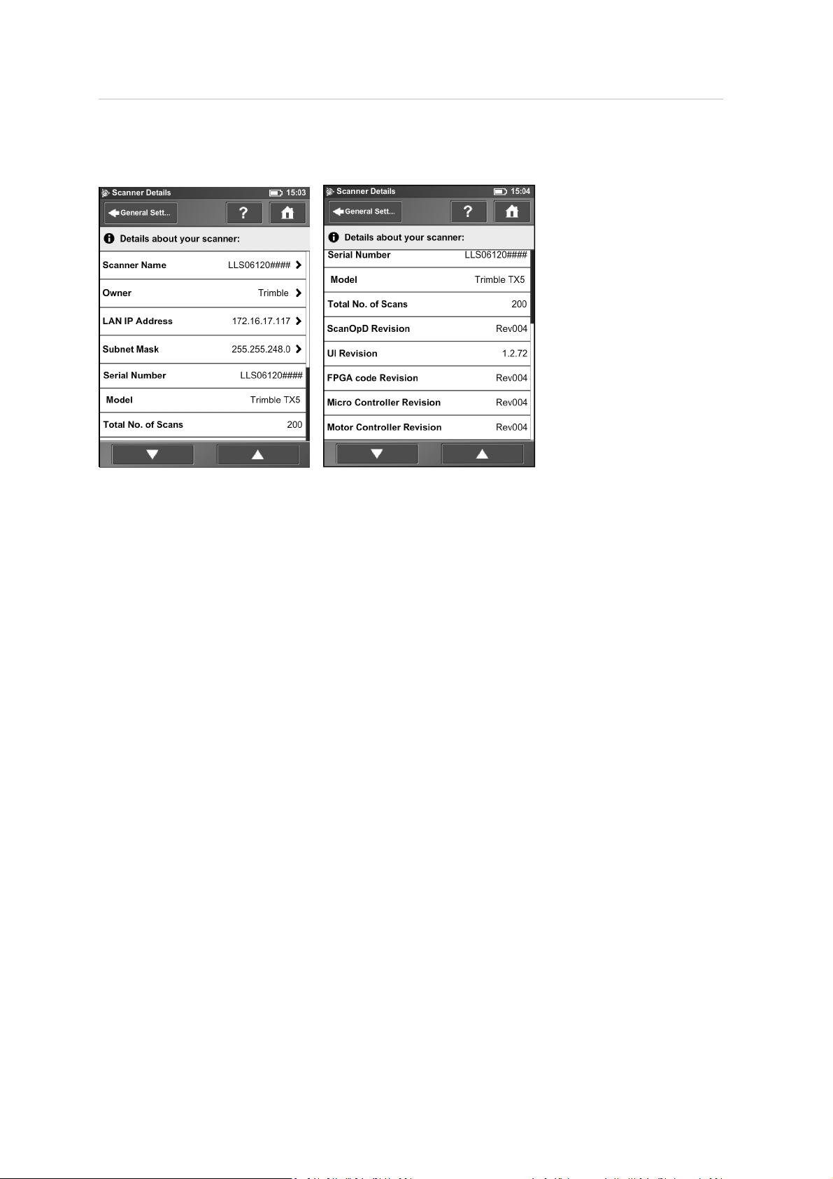
5 TX5 Controller Software
Scanner Details
Scanner Name – Give your scanner a name.
Owner – Enter the owner of the scanner.
LAN IP Address – The Ethernet IP address of the scanner.
Subnet Mask – The Ethernet subnet mask of the scanner.
Serial Number – Serial number of the scanner. This number is individual for each scanner.
Model – The scanner type.
Total No. of Scans – The total number of scans captured with this scanner.
ScanOpD / UI / FPGA code / Micro controller / Motor Controller Revisions – The revision numbers of
the scanner firmware.
Trimble TX5 3D Laser Scanner User Guide 92
Page 93
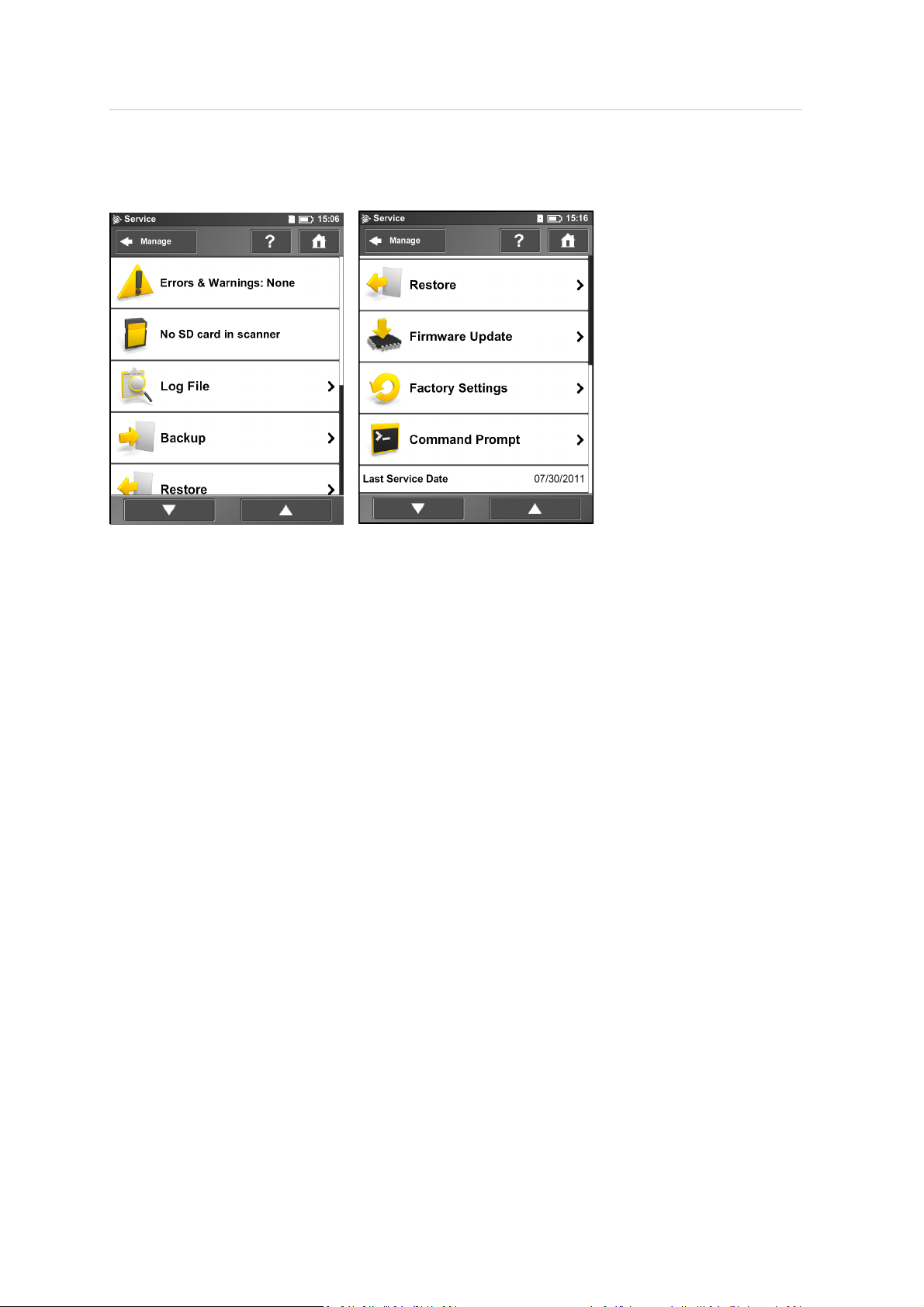
5 TX5 Controller Software
Service
Errors & Warnings – Tap to change to another screen to view details of present warnings and errors.
If there are no warnings or errors, tapping this field has no effect. See Errors and Warnings, page 94.
SD Card – View details about the currently inserted SD card or format the SD card. See SD Card, page
95.
Log file – Export the log file to the SD card. See Log File, page 95.
Backup – Backup scan profiles, operators, wallpapers and scanner parameters as scanner snapshots
to the SD card. See Backup, page 96.
Restore – Restore scan profiles, operators, wallpapers and scanner parameters from scanner
snapshots or restore scanner snapshots that have been created with TX5 SCENE software. See
Restore, page 97.
Firmware update – Update the scanner with new firmware versions. See FirmwareUpdate, page 98.
Factory Settings – Reset the scanner to its factory settings. See Factory Settings, page 99.
Command Prompt – Command prompt to send commands to the scanner. This function is for
Trimble Support purposes only.
Last Service Date – Date of the last scanner maintenance and certification service.
Trimble TX5 3D Laser Scanner User Guide 93
Page 94
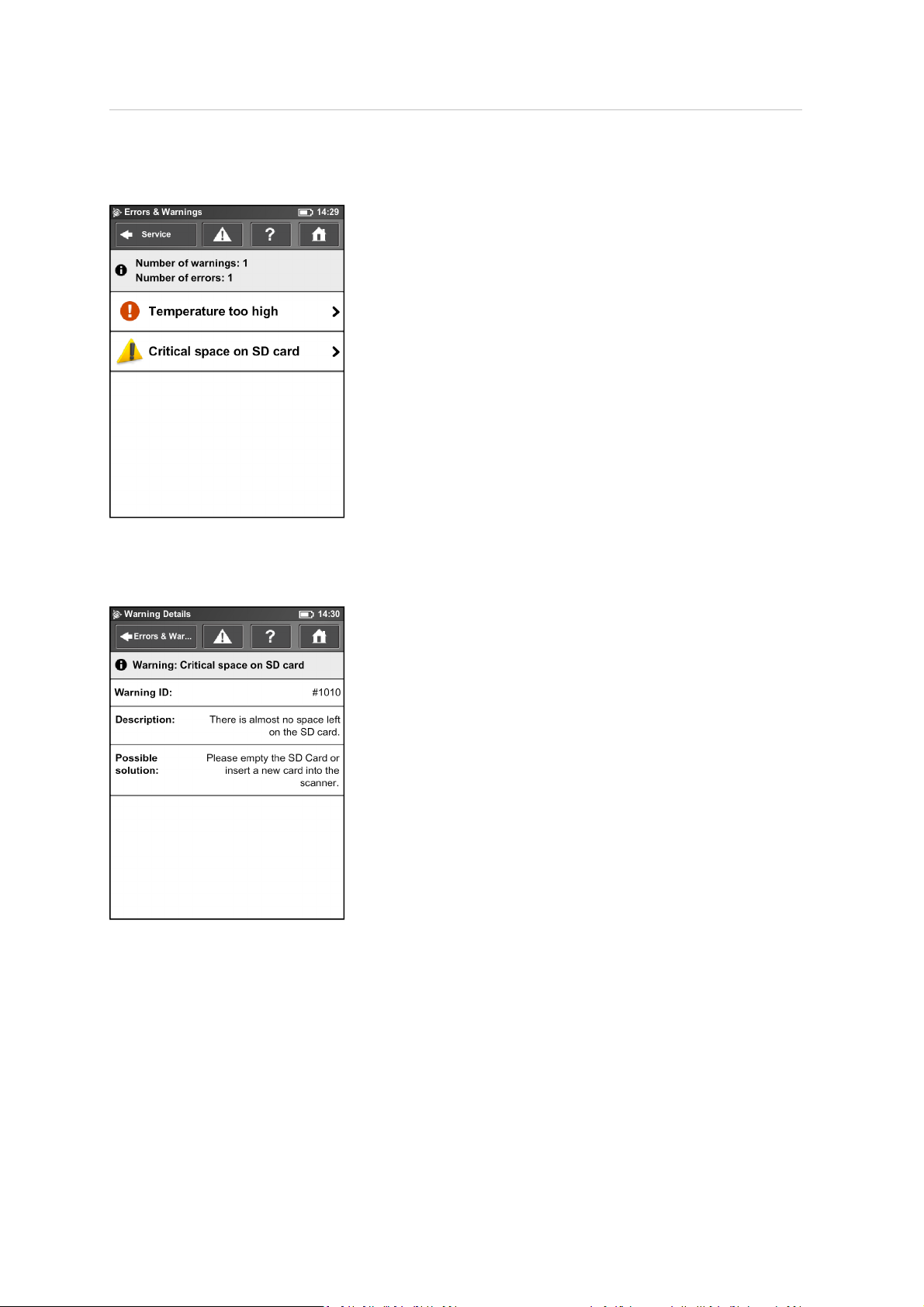
5 TX5 Controller Software
Errors and Warnings
This view provides a list of present warnings and errors. Tap a list item to view details of the
corresponding warning or error.
Warnings and errors disappear from the list when they are fixed.
This screen shows a description of the warning or error and provides a possible solution to solve the
problem.
Warning ID / Error ID – The identification number of the warning or error.
Description – A detailed description of the warning or error.
Possible solution – Possible solution to solve the problem.
Trimble TX5 3D Laser Scanner User Guide 94
Page 95
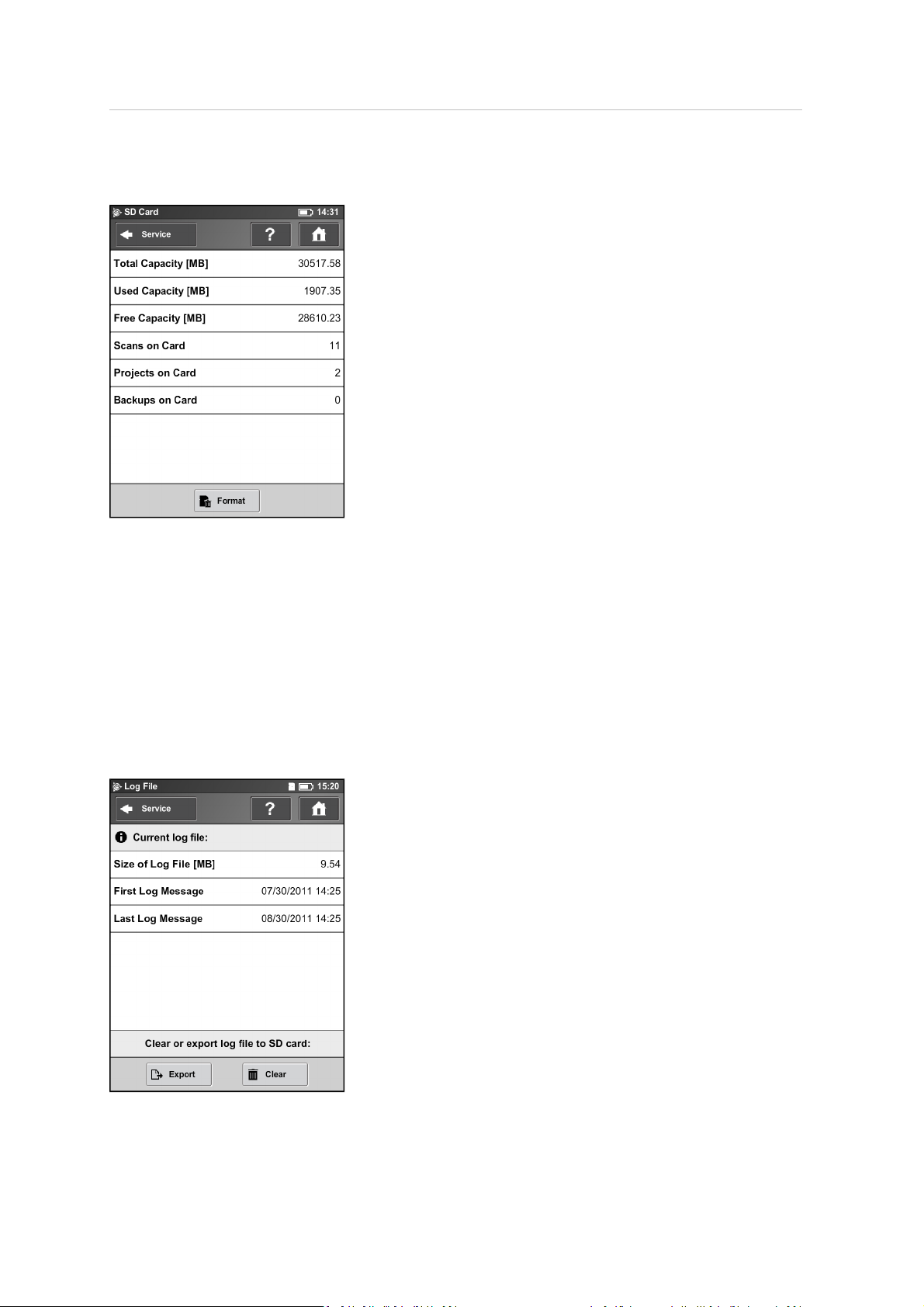
5 TX5 Controller Software
SD Card
This view provides information about the currently inserted SD card and its contents.
Format Card – Format the inserted SD card.
Note – This operation deletes all scans and other data from the SD card. Always use the Format
Card option before you begin using an SDXC card with a capacity of 64GB or more as Windows
formats such cards with their own file system which is not supported by the scanner. For more
information, see Using an SD memory card, page 38.
Log File
Important scanner operations, sensor data as well as warnings and errors are saved to the log file to
identify problems and the cause of possible errors.
Trimble TX5 3D Laser Scanner User Guide 95
Page 96
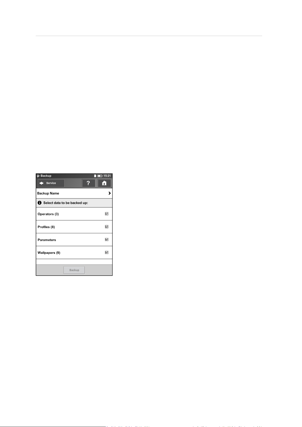
5 TX5 Controller Software
Export – Writes the scanner log file to the SD card. It will be saved to a folder called “Logfile”.
Clear – Clears the contents of the log fileon the scanner.
Backup
The scanner creates an automatic backup of the scanner settings and saves it to the inserted SD
card. This backup is automatically updated with the current scanner settings each time you start a
scan. It includes the current scan profiles, scanning parameters, operators, wallpapers and general
settings.
You can create manual backups of some scanner settings including scanner parameters, operators,
scan profiles, and wallpapers.
The manual backup option creates snapshots of scanner data and helps you to protect it from
accidental loss if your scanner's hardware or storage media fails. It creates a duplicate copy of the
data on your SD card; you can then archive the data on another storage device or modify it with TX5
SCENE software and transfer the modified data back to your scanner.
If you own more than one scanner, you can also transfer operators, scan profiles or wallpapers from
one scanner to another without the need of entering the data individually.
Backup Name – Click to enter the name of the backup package. Data will be saved to the following
directory on your SD card: /Backup/Your_backup_name/.
After having specified the name of the backup folder, select the data you want to backup and then
tap Backup to start the operation.
Note – The number next to each field identifies the number of each item type on the scanner.
Trimble TX5 3D Laser Scanner User Guide 96
Page 97
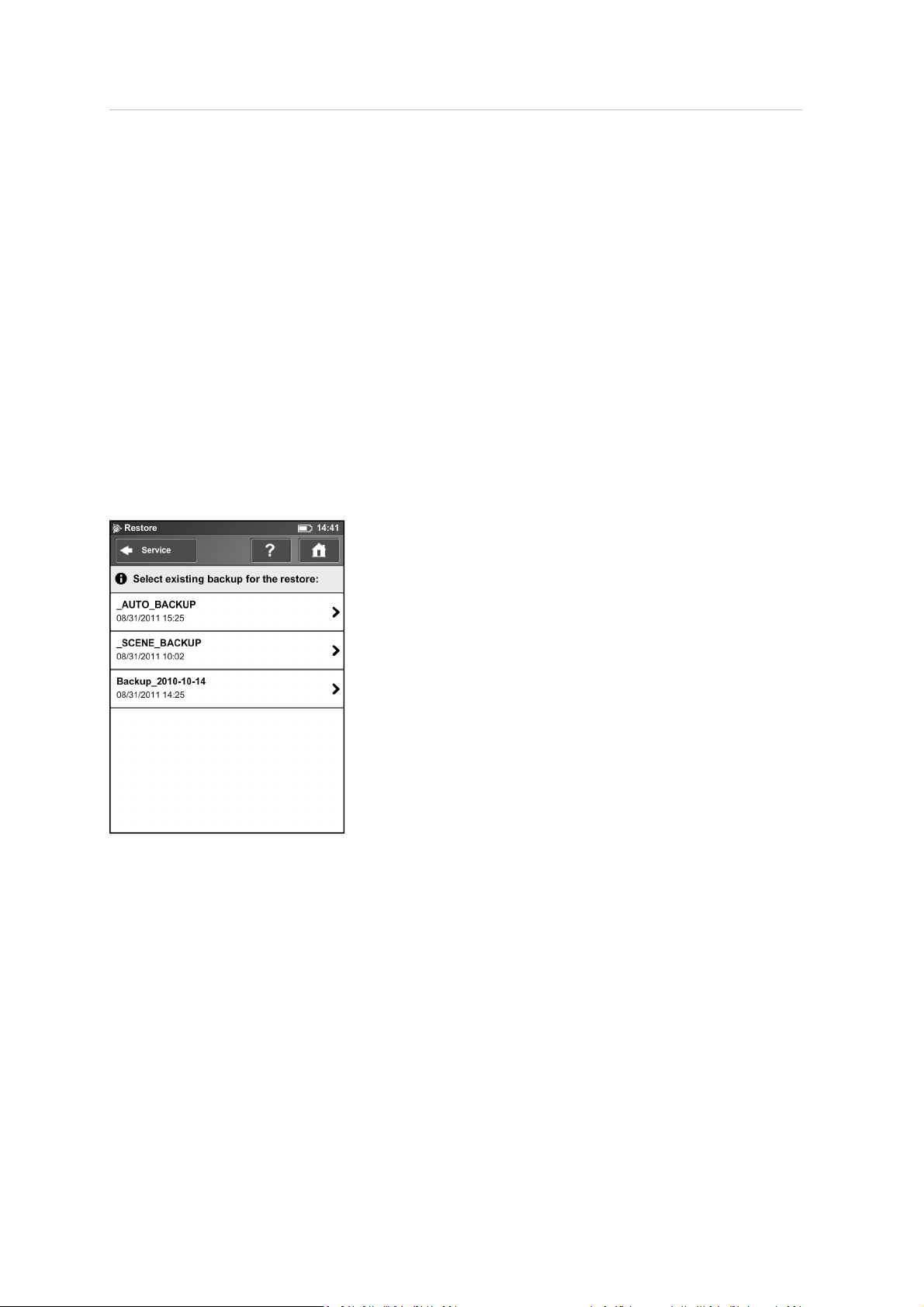
5 TX5 Controller Software
Restore
With this function you can:
l
restore operators, scan profiles, scanner parameters and wallpapers from archived backups or
scanner snapshots.
l
import operators, profiles and wallpapers that were created with TX5 SCENE software.
l
import formerly backed up operators, profiles and wallpapers that were modified with TX5
SCENE software.
l
import operators, profiles, wallpapers and scanner parameters from other scanners.
To restore data, it must be saved to an SD card. For this, create a directory on the SD card named
“Backup”, and then copy the folder with the data you want to restore to this directory. If you use
TX5 SCENE software to create new or modify backed up data, this is automatically done by the
software.
When finished, insert the SD card with the data you want to restore.
This screen shows you a list of all backup packages on the inserted SD card. _AUTO_BACKUP is the
automatically generated scanner snapshot (see Backup, page 96). _SCENE_BACKUP is the scanner
snapshot that has been created or modified with the TX5 SCENEsoftware. Tap the backup package
you want to restore. A new screen appears.
Trimble TX5 3D Laser Scanner User Guide 97
Page 98
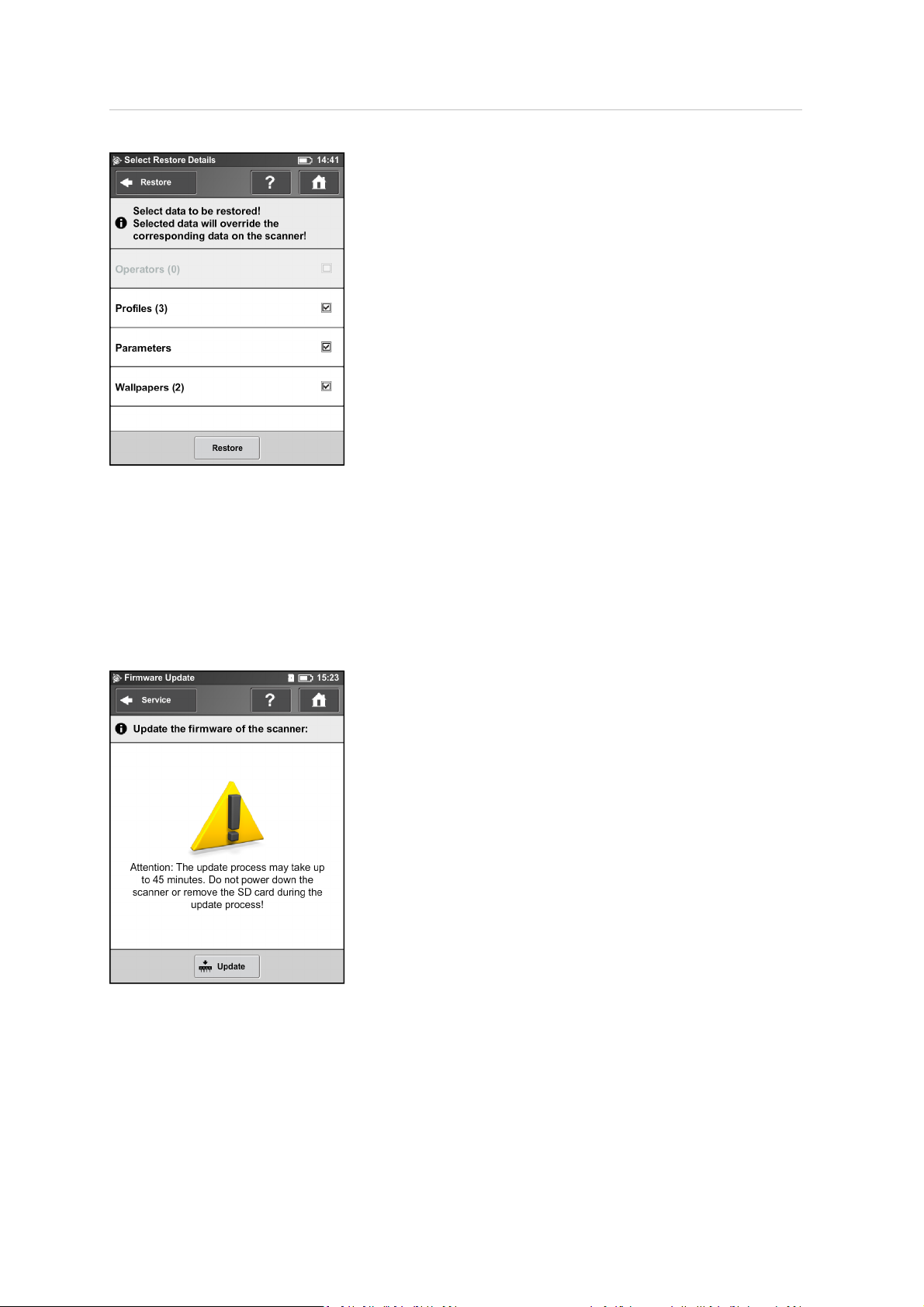
5 TX5 Controller Software
Select the data from the backup package you want to restore and tap Restore to start the restore
operation.
Note – The restored data will override existing data on the scanner. For example, to restore or
import scan profiles, all the existing scan profiles on the scanner are overridden by the new profiles.
The scanner's default profiles remain unaffected from this operation. Trimble recommends backing
up your data before restoring.
Firmware Update
To update the firmwareof your TX5 3D laserscanner you must first copy the update file to the folder
“Updates” on your SD card. If this folder does not exist, create it manually.
Trimble TX5 3D Laser Scanner User Guide 98
Page 99
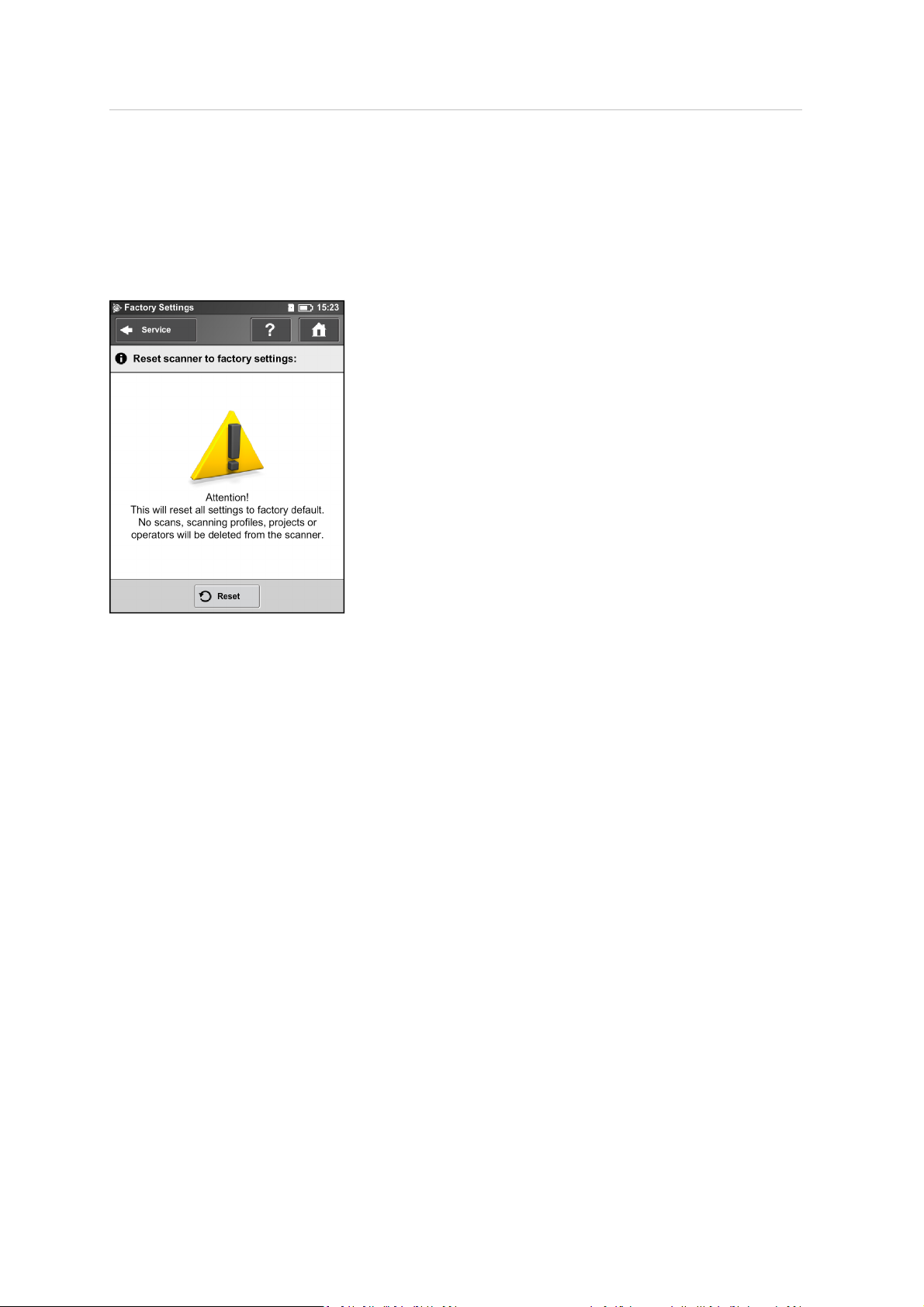
5 TX5 Controller Software
Insert the SD card with a firmware update file, and then tap Update. The update process may take
up to 30 or 40 minutes, depending on the extent of the update. Do not manually shut down or
power off the scanner during the update process.
After the update is completethe scanner might restart automatically.
Factory Settings
This function resets your scanner settings to factory default. Use this option in exceptional cases
only.
Your scans, scan profiles, scan projects or operators that are saved on the scanner remain
unaffected by this operation.
Trimble TX5 3D Laser Scanner User Guide 99
Page 100
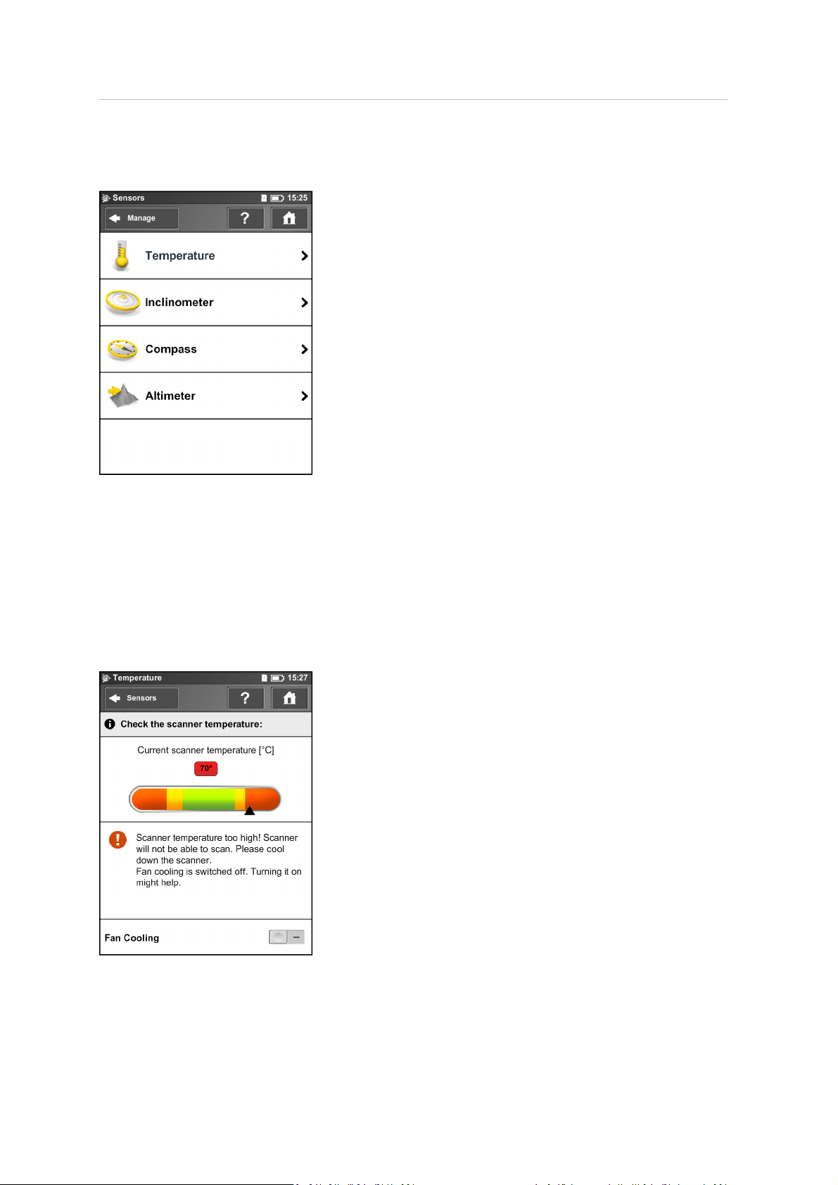
5 TX5 Controller Software
Sensors
Temperature – Tap to viewthe current scanner temperature and to switch the scanner's fan on or
off. See Temperature Sensors, page 100.
Inclinometer – Tap to level the scanner. See Inclinometer (Dual Axis Compensator), page 101.
Compass – Tap to viewthe orientation of the scanner. See Compass, page 102.
Altimeter – Tap to view the currently measured altitude of the scanner‘s position and to sync the
altimeterwith a reference height. See Altimeter, page 103.
Temperature Sensors
Trimble TX5 3D Laser Scanner User Guide 100
 Loading...