

Page 1

TRIMTALK 450S
Operation Manual
Part Number: 28964-00
Revision: B
Date: November 1998
Trimble Navigation Limited
645 North Mary Avenue
P.O. Box 3642
Sunnyvale, CA 94088-3642
U.S.A.
1-800-827-8000 in North America
+1-408-481-8000 International
Fax: +1-408-481-7744
www.trimble.com
Page 2

Trimble Navigation Europe Limited
Trimble House, Meridian Office Park
Osborn Way, Hook
Hampshire RG27 9HX
ENGLAND
+44-1256-760-150
Fax: +44-1256-760-148
Voicemail: +44-1256-761-130
Trimble Navigation Singapore PTE Limited
79 Anson Road
# 05-02
Singapore 079906
SINGAPORE
+65-325-5668
Fax: +65-225-9989
Voicemail: +65-325-5668
Trimble Japan K.K.
Sumitomo Hamamatsu-cho, Building 10F
1-18-16 Hamamatsu-cho Minato-ku
Tokyo 105
JAP AN
+81-3-5472-0880
Fax: +81-3-5472-2326
Trimble Navigation New Zealand Limited
11 Birmingham Dr i ve
P.O. Box 8729 Riccarton
Christchurch
NEW ZEALAND
+64-3-339-1400
Fax: +64-3-339-1417
Copyright
© 1998 Trimble Navigation Limited. All rights reserved. No part of this manual may be
copied, photocopied, reproduced, translated, or reduced to any electronic medium or machinereadable form without prior written consent from Trimble Navigation Limited.
Printed in the United States of America. Printed on recycled paper.
Page 3

Revision Notice
This is the November 1998 release (Revision B) of the
TRIMTALK 450S Operation Manual
,
part number 28964-00.
Trademarks
TRIMTALK 450S, TRIMTALK 900, RTK, OSM2, 4000Si, 4000SSi, 4600LS, 4700, 4800,
7400MSi, and GPS Total Station are trademarks of Trimble Navigation Limited. IBM is a
registered trademark of International Business Machines, Inc. MS-DOS and Windows are
trademarks of Microsoft Corporation. Intel is a trademark of Intel Corporation. All other brand
names are trademarks of their respective holders.
Safety
Exposure to RF energy is an important safety consideration. The Institute of Electrical and
Electronic Engineers (IEEE), the U.S. Department of the Navy, and the American National
Standards Institute (ANSI) created a standard set of guidelines titled
to Human Exposure to Radio Frequency Electromagnetic Fields, 300 kHz to 100 GHz
Safety Levels with Respect
. Based
on a wide variety of tests, the standard excludes from concern, devices that emit less than 7
watts at frequencies between 300 kHz and 1 GHz. The TRIMTALK 450S antenna emits less
than 0.5 watts on average at 430 to 470 MHz and is considered extremely safe. However, due
to the extreme sensitivity of human tissue to heating effects, Trimble recommends maintaining
a distance of at least 0.3 meter (one foot) from a TRIMTALK 450S base or repeater antenna.
The Trimble rover antenna is receive only and is safe at all distances.
Disclaimer of Warranty
E
XCEPT AS INDICATED IN
F
IRMWARE AND DOCUMENTATION IS PROVIDED “AS IS” AND WITHOUT EXPRESS OR LIMITED
WARRANTY OF ANY KIND BY EITHER TRIMBLE NAVIGATION LIMITED OR ANYONE WHO HAS
BEEN INVOLVED IN ITS CREATION, PRODUCTION, OR DISTRIBUTION INCLUDING BUT NOT
LIMITED TO THE IMPLIED WARRANTIES OF MERCHANTABILITY AND FITNESS FOR A PARTICULAR
PURPOSE
H
NOT ALLOW THE EXCLUSION OF IMPLIED WARRANTIES, SO THE ABOVE EXCLUSION MAY NOT
APPLY TO YOU
. THE
ARDWARE
ENTIRE RISK, AS TO THE QUALITY AND PERFORMANCE OF THE TRIMBLE
, S
OFTWARE
.
“L
IMITED WARRANTY” HEREIN
, F
IRMWARE AND DOCUMENTATION, IS WITH YOU
, T
RIMBLE HARDWARE
, S
OFTWARE
. S
OME STATES DO
,
Page 4

Limitation of Liability
I
N NO EVENT WILL TRIMBLE NAVIGATION LIMITED OR ANY PERSON INVOLVED IN THE
CREATION, PRODUCTION, OR DISTRIBUTION OF THE TRIMBLE PRODUCT BE LIABLE TO YOU ON
ACCOUNT OF ANY CLAIM FOR ANY DAMAGES, INCLUDING ANY LOST PROFITS, LOST SAVINGS
OR OTHER SPECIAL, INCIDENTAL, CONSEQUENTIAL, OR EXEMPLARY DAMAGES, INCLUDING BUT
NOT LIMITED TO ANY DAMAGES ASSESSED AGAINST OR PAID BY YOU TO ANY THIRD PARTY
RISING OUT OF THE USE, LIABILITY TO USE, QUALITY OR PERFORMANCE OF SUCH TRIMBLE
P
RODUCT INCLUDING HARDWARE, SOFTWARE, FIRMWARE AND DOCUMENTATION, EVEN IF
T
RIMBLE NAVIGATION LIMITED OR ANY SUCH PERSON OR ENTITY HAS BEEN ADVISED OF THE
POSSIBILITY OF DAMAGES, OR FOR ANY CLAIM BY ANY OTHER PARTY
ALLOW THE LIMITATION OR EXCLUSION OF LIABILITY FOR INCIDENTAL OR CONSEQUENTIAL
DAMAGES SO, THE ABOVE LIMITATIONS MAY NOT APPLY TO YOU
. S
OME STATES DO NOT
.
,
,
Software and Firmware Limited Warranty
Trimble Navigation Limited warrants that Software and Firmware products will substantially
conform to the published specifications provided it is used with the Trimble products,
computer products, and oper ating system for which it was designed. F or a period of ninety (90)
days, commencing thirty (30) days after shipment from Trimble, Trimble also warrants that the
magnetic media on which Software and Firmware are distributed and the documentation are
free from defects in materials and workmanship. During the ninety (90) day warranty period,
Trimble will replace defecti v e media or docu mentation, or corr ect substantial program errors at
no charge. If Trimble is unable to replace defective media or documentation, or correct
program errors, Trimble will refund the price paid for The Software. These are your sole
remedies for any breach in warranty.
Page 5

Hardware Limited Warranty
Trimble Navigation Limited products are warranted against defects in material and
workmanship for a period of one year. The warranty period shall commence thirty (30) days
after shipment from Trimble’s factory. Warranty service will be provided at a designated
Trimble Service Center . T rimble will at its option either repair or replace products that prove to
be defective. The Customer shall pay all shipping charges for products returned to Trimble for
warranty service. Trimble shall pay all shipping charges for the return of products to the
Customer. The above warranty shall not apply to defects resulting from:
1. Improper or inadequate maintenance by the buyer
2. Buyer-supplied software or interfacing
3. Unauthorized modification or misuse
4. Operation outside of the environmental specifications of the product
5. Improper installation, where applicable
6. Lightning or other electrical discharge
7. Fresh or salt water immersion or spray
8. Normal wear and tear on consumable parts (for example, batteries)
No other warranty is expressed or implied. Trimble Navigation Limited specifically disclaims
the implied warranties of fitness for a particular purpose and merchantability.
Page 6

Page 7

Table of Contents
Preface
Scope and Audience . . . . . . . . . . . . . . . . . . . . . . . . .xv
Organization . . . . . . . . . . . . . . . . . . . . . . . . . . . . .xv
Related Information . . . . . . . . . . . . . . . . . . . . . . . . .xvi
Update Notes . . . . . . . . . . . . . . . . . . . . . . .xvi
Technical Assistance. . . . . . . . . . . . . . . . . . . .xvii
Reader Comment Form. . . . . . . . . . . . . . . . . . . . . . . .xviii
Document Conventions. . . . . . . . . . . . . . . . . . . . . . . .xviii
Notes, Tips, Cautions, and Warnings . . . . . . . . . . . . . . . . .xix
1 Overview
1.1 TRIMTALK 450S Network . . . . . . . . . . . . . . . . . . . . .1-1
1.1.1 Radio Link. . . . . . . . . . . . . . . . . . . . . . . . .1-2
1.1.2 Features . . . . . . . . . . . . . . . . . . . . . . . . . .1-3
1.1.3 Standard Equipment Sets . . . . . . . . . . . . . . . . .1-4
1.1.4 Accessories . . . . . . . . . . . . . . . . . . . . . . . .1-5
4800 Receiver Accessories . . . . . . . . . . . . . . . .1-5
Series 4000, 4400, and 4600 Receiver Accessories. . . .1-6
Additional Accessories . . . . . . . . . . . . . . . . . .1-6
1.2 Description . . . . . . . . . . . . . . . . . . . . . . . . . . . . . .1-7
1.2.1 Controls and Indicators . . . . . . . . . . . . . . . . . .1-8
1.2.2 Power and I/O Cables . . . . . . . . . . . . . . . . . . .1-9
1.3 Antenna Description . . . . . . . . . . . . . . . . . . . . . . . . .1-11
TRIMTALK 450S Operation Manual vii
Page 8

Table of Contents
2 Operation
2.1 Configuration. . . . . . . . . . . . . . . . . . . . . . . . . . . . .2-1
2.1.1 Configuring the Serial I/O Port . . . . . . . . . . . . . .2-2
Connecting to a Computer. . . . . . . . . . . . . . . . .2-2
Installing the TRIMTALK Setup Utility . . . . . . . . .2-3
Using the TRIMTALK Setup Utility . . . . . . . . . . .2-3
2.1.2 Configuring the Wireless Data Link. . . . . . . . . . . .2-5
2.1.3 Updating the List of Available Frequencies . . . . . . . .2-7
2.2 Installation . . . . . . . . . . . . . . . . . . . . . . . . . . . . . .2-8
2.2.1 Installation as a Repeater . . . . . . . . . . . . . . . . .2-9
2.3 Antenna Installation . . . . . . . . . . . . . . . . . . . . . . . . .2-10
3 Characteristics and Specifications
3.1 Antenna Gain . . . . . . . . . . . . . . . . . . . . . . . . . . . .3-1
3.1.1 Omnidirectional Antennas. . . . . . . . . . . . . . . . .3-2
3.1.2 Directional Antennas . . . . . . . . . . . . . . . . . . .3-4
3.2 Point-To-Point Link . . . . . . . . . . . . . . . . . . . . . . . . .3-6
3.2.1 Frequency Band and Channel Selection. . . . . . . . . .3-8
3.2.2 Wireless Data Rate. . . . . . . . . . . . . . . . . . . . .3-9
3.2.3 RF Output Power . . . . . . . . . . . . . . . . . . . . .3-9
3.3 Electrical Interface . . . . . . . . . . . . . . . . . . . . . . . . . .3-10
3.3.1 Power Consumption . . . . . . . . . . . . . . . . . . . .3-12
3.4 Specifications. . . . . . . . . . . . . . . . . . . . . . . . . . . . .3-13
A Equipment Sets and Accessories
B Regulations
B.1 Operator’s Permit or License . . . . . . . . . . . . . . . . . . . . .B-1
B.2 Type Approval . . . . . . . . . . . . . . . . . . . . . . . . . . . .B-2
viii TRIMTALK 450S Operation Manual
Page 9

Index
Table of Contents
TRIMTALK 450S Operation Manual ix
Page 10

Table of Contents
x TRIMTALK 450S Operation Manual
Page 11

List of Figures
Figure 1-1 TRIMTALK 450S Front Panel . . . . . . . . . . . . . 1-7
Figure 1-2 TRIMTALK 450S Rear Panel . . . . . . . . . . . . . 1-8
Figure 1-3 Cables. . . . . . . . . . . . . . . . . . . . . . . 1-10
Figure 2-1 TRIMTALK Setup Main Window . . . . . . . . . . . . 2-3
Figure 2-2 TRIMTALK 450S Setup Window . . . . . . . . . . . . 2-5
Figure 2-3 Standard Omnidirectional Antenna . . . . . . . . . . . 2-11
Figure 2-4 Directional Antennas . . . . . . . . . . . . . . . . . 2-12
Figure 3-1 Omnidirectional Antenna Gain Patterns. . . . . . . . . . 3-2
Figure 3-2 Directional Antenna Gain Patterns. . . . . . . . . . . . 3-4
Figure 3-3 Typical Range Limits Without Obstructions . . . . . . . . 3-6
TRIMTALK 450S Operation Manual xi
Page 12

List of Figures
xii TRIMTALK 450S Operation Manual
Page 13

List of Tables
Table 2-1 Determining Network Repeater Quantity . . . . . . . . . 2-9
Table 2-2 Cable Losses . . . . . . . . . . . . . . . . . . . . 2-10
Table 3-1 Wireless Data Rates . . . . . . . . . . . . . . . . . 3-9
Table 3-2 POWER I/O Connector Pinout . . . . . . . . . . . . . 3-10
Table 3-3 AUX I/O Connector Pinout . . . . . . . . . . . . . . 3-11
Table 3-4 Power Consumption Values (Approximate) . . . . . . . . 3-12
Table 3-5 Radio Modem Physical Specifications . . . . . . . . . . 3-13
Table 3-6 Antenna Physical Specifications . . . . . . . . . . . . 3-13
Table 3-7 Performance Specifications (Typical) . . . . . . . . . . 3-14
Table A-1 Equipment Sets . . . . . . . . . . . . . . . . . . . A-1
Table A-2 Accessories. . . . . . . . . . . . . . . . . . . . . A-2
TRIMTALK 450S Operation Manual xiii
Page 14

List of Tables
xiv TRIMTALK 450S Operation Manual
Page 15

Preface
Welcome to the
describes the TRIMTALK 450S radio modem for real-time
differential and real-time kinematic GPS applications. This radio
modem provides a high-speed wireless data link between base and
rover GPS receivers, and optional repeaters.
Scope and Audience
We recommend that you spend some time reading this manual. The
following s ection pr ov ides yo u with a g uid e to th is manua l, as wel l as
to other documentation you have received with this product.
Organization
This manual contains the following chapters and appendices:
•
Chapter 1, Overvie w - provid es a brief o v ervie w and ph ysical
description of the TRIMTALK 450S radio modem.
•
Chapter 2, Operation - contains complete installation and
configuration instructions for the TRIMTALK 450S radio
modem.
TRIMTALK
™
450S Operation Manual
. This manual
•
Chapter 3, Characteristics and Specifications - summarizes
performance characteristics and specifications that can be
expected from a TRIMTALK 450S network.
TRIMTALK 450S Operation Manual xv
Page 16

Preface
•
Appendix A, Equipment Sets and Ac cessories - contains part
numbers of items in standard equipment sets as well as
additional accessories.
•
Appendix B, Regulations an d Safety - contains re gulation and
safety information.
Related Information
This manual contains system-wide, general information on the
TRIMTALK 450S. Other sources of information are discussed in the
following sec tions.
Update Notes
You will find a Warranty Activation Sheet wi th your TRIMTALK
450S. By sending in your Warranty Activation Sheet, you are
automatically sent update notes as they become available. When you
receive these packages, read them. They contain important
information abo ut softw are and ha rdwa re changes. Contact your loca l
Trimble Dealer for more information about support agreement
contracts for s oftware and f irmw are, and e xt ended war ranty programs
for hardware.
xvi TRIMTA LK 450S Op erati on Manual
Page 17

Technical Assistance
If you hav e a prob lem and cannot fi nd the inf ormation you need in the
product documentation,
If you need further assistance, contact the Trimble Technical
Assistance Center (TAC) by phone, fax, or email. A support
technician can help determine the cause of the problem and provide
technical assistance.
To contact TAC:
Phone: +1-800-SOS-4TAC (North America)
+1-408-481-6940 (International)
Phones are answered from 6:00 am to 5.30 pm
Pacific Standard Time.
Fax: +1-408-481-6020
Email: [email protected]
When you contact TAC, provide the following information:
•
The Tri mble product name, any softw ar e or firmware version
number(s), and if appropriate, the serial number.
contact your local dealer
Preface
.
•
Your specific question or problem.
Please detail background information, such as the
configuration of your data logger or receiver, and the exact
type, make, and configuration of your computer. If you have
received error messages, please specify the exact wording.
If you need to send a data file with your inquiry, please compress the
file using PKZIP software by PKWARE, Inc., and name the file with
the extension.ZIP.
Use one of the following methods to send the file:
•
Attach the file to your email inquiry.
•
Put the file on t he Trimble FTP site and incl ude the file name
in your email inquiry.
TRIMTALK 450S Operation Manual xvii
Page 18

Preface
Reader Comment Form
A reader comment form is provided at the end of this guide. If this
form is not available, comments and suggestions can be sent to
Trimble Navigation Limited, 645 North Mary Avenue, Post Office
Box 3642, Sunnyvale, CA 94088-3642. All comments and
suggestions become the property of Trimble Navigation Limited.
Document Conventions
identify software menus, menu commands, dialog boxes, and
Italics
the dialog box fields.
SMALL CAPITALS
and filename extensions.
Courier
the DOS system or program.
Courier Bold
software screen or window.
[Return]
combination that you must press on a PC.
Helvetica Bold
is used to represent what you see printed on the screen by
or
[Ctrl]
identify DOS commands, directories, filenames,
represents information that you must type in a
+
identifies a hardware function key or key
[C]
represents a software command button.
xviii TRIMTALK 450S Operation Manual
Page 19

Notes, Tips, Cautions, and Warnings
Notes, tips, cautions, and warnings are used to emphasize important
information.
Preface
*
F
I
M
Note – Notes give additional significant information about the subject
to increase your knowledge or guide your actions. A note can precede
or follow the text it references.
Tip – Indicates a shortcut or other time or labor-saving hint that can
help you make better use of the TRIMTALK 450S.
Caution – Cautions alert you to situations that could cause hardware
damage or software error. A caution precedes the text it references.
Warning – Warnings alert you to situations that could cause personal
injury or unrecoverable data loss. A warning precedes the text it
references.
TRIMTALK 450S Operation Manual xix
Page 20

Preface
xx TRIMTALK 450S Operation Manual
Page 21

1 Overview
A set of TRIMTALK 450S radio modems form a wireless data
network. The unit is designed primarily for broadcasting low-latency
differential GP S (DGPS) corrections or raw GPS data from a survey
base receiver to one or more roving receivers for real-time differential
or real-time kinematic (RTK) GPS surveying.
1.1 TRIMTALK 450S Network
The base, rove rs, and repea ters in a TRIMTALK 450S netwo rk are all
identical units. The function of a particular unit (base, rover, or
repeater) is determined by its configuration. Units used as a base or
rover can be connected to most Trimble su rvey-grade GPS receivers
through a single cable for both power and serial I/O.
To achieve l ine-o f-sig ht (LOS) co v era ge t o all point s in a s urv e y a rea,
a TRIMTALK 450S network can include up to two repeaters. The
repeaters retransmit data packets according to a simple time-sharing
scheme to avoid mutual interference. The operation of the repeaters is
transparent to the rovers. A rover can move around and pick up data
packets from the base or repeaters, whichever the rover hears first.
Repeaters operate autonomously, they do not require anything
connected to their serial ports. TRIMTALK 450S radio modems also
have an auxiliary I/O connector that can configure the radio.
Whether one or two repeaters can be used in your TRIMTALK 450S
network is determined by the wireless data rate and information
content. To use two repeat ers, the wir eless data ra te mu st be 9600 bps
and the information cont ent must be T rimble CMR2 RTK packets at a
1 Hz rate.
TRIMTALK 450S Operation Manual 1-1
Page 22

Overview
1.1.1 Radio Link
1
The TRIMTALK 450S radio modem operates i n on e of the following
frequency bands:
•
430-440 MHz
•
440-450 MHz
•
450-460 MHz
•
460-470 MHz.
The unit only operates in one of these bands, not across bands. If
multiple band coverage is needed, multiple TRIMTALK 450S radio
modems are required, with each unit covering one of the bands.
The TRIMTALK 450S radio modem stores up to 20 factory preprogrammed frequencies, and operates on one of these frequencies,
depending on which is selected.
*
1-2 TRIMTALK 450S Operation Manual
Note – Each
tuned to the same frequency for the network to operate.
The output power of the TRIMTALK 450S radio modem is slightly
less than 0.5 watt. The channel spacing can be 12.5 kHz or 25 kHz,
dependent on country re gula tions. The wireless data rate can be 1200,
2400, 4800, or 9600 bps for u nits with 2 5 kHz ch annel s pacing . Unit s
with 12.5 kHz channel spacing are limited to a maximum of 4800
bps.
Regulations regarding the use of the TRIMTALK 450S radio modem
vary greatly from country to country. In some countries, the unit can
be used without obt aining an end -user lice nse. Other countries r equire
end-user licensing. Contact your Trimble dealer for regulations and
restrictions on operation in the count ry or area whe re you are go ing to
use the TRIMTALK 450S radio modem.
TRIMTALK 450S
radio modem in a network must be
Page 23

1
1.1.2 Features
Overview
The local interf ace t o a unit i s throu gh an a synchro nous ser ial po rt . In
its normal mode of operation, a base survey receiver passes data to a
TRIMTALK 450S radio modem over its serial port. The units then
transmits this data to all of the rovers on the network.
The following are features of the TRIMTALK 450S radio modem:
•
Up to 20 factory pre-programmed channels
•
Narrowband UHF technology
•
Up to 10 km line-of-sight range under optimal conditions
(3 to 5 km, typical)
•
Selectable wireless data rates of 1200, 2400, 4800, and 9600
bps
•
Compatible with T rimbl e 4700, 4800, and other T r imble GP S
receiv ers
•
Capable of supporting up to two repeaters in a single networ k
•
Rugged, weatherproof construct i on
•
Low power consumption
•
RS-232 interface
TRIMTALK 450S Operation Manual 1-3
Page 24

Overview
1.1.3 Standard Equipment Sets
The basic building bl ocks for a TRIMTALK 450S networ k consist of
the base, rover, and optional repeaters. An equipment set exists for
each of these containing the essential items required for operation.
1
*
*
Note – If a Trimble 4700 or 4800 GPS receiver with an internal radio
modem is used as a rover, an external rover radio modem may not be
needed.
The Base Equipment Set contains a TRIMTALK 450S radio modem,
an antenna with two tips (0 dB and 5 dB), a 50-foot power and I/O
cable, and a tripod mount with an antenna cable.
The Repeater Equipment Set contains a TRIMTALK 450S radio
modem, an antenna with two tips (0 dB and 5 dB), a tripod mount
with an antenna cable, a 6 Amp-Hour battery with cable, and an
adapter cab le.
The Rover Equipment Set contains a TRIMTALK 450S radio
modem, an antenna with tw o ti ps (0 dB and 5 dB), a 3-f oot po wer and
I/O cable, and a backpack mount.
Note – The standard equipment sets are designed for use with GPS
receivers such as the Trimble 4700 and 4800. Please consult the
Accessories, page 1-5 for information on connecting the TRIMTALK
450S radio modem to other GPS receivers.
1-4 TRIMTALK 450S Operation Manual
Page 25

1
1.1.4 Accessories
Descriptions and part numbers for the standard equipment sets and
for the accessories are given in Appendix A, Equipment Sets and
Accessories. The following discussion tells how these items are used.
4800 Receiver Accessories
T o use a 4800 rov er with an exter nal TRIMTALK 450S radio modem,
a cable kit must be purchas ed. Th e cab le kit consists of a Y-cable and
a 3-foot power and I/O cable (1-shell to 1-shell). The kit enables the
user to connect the TRIMTALK 450S radio modem to Port 3 of the
4800 and also to a power source such as a Li-Ion PowerLITE battery
or a camcorder battery.
The following accessories allow the TRIMTALK 450S to be used
with a 4800 receiver used as a rover:
•
•
Overview
Cable kit for use with a 4800 rover and an external radio
modem
Li-Ion PowerLITE battery cable
•
Li-Ion PowerLITE battery
•
Camcorder battery cable
•
Camcorder battery
TRIMTALK 450S Operation Manual 1-5
Page 26

Overview
Series 4000, 4400, and 4600 Receiver Accessories
The data cables pro vided with the standard base and rov e r equipment
sets are not compatible with GPS receivers such as Trimble Series
4000, Site Surveyor 4400 and the 4600LS . The follo wing cable s must
be purchased to use TRIMTALK 450S radio modems with these GPS
receiv ers:
•
50-foot power and I/O cable (1-shell to 1-shell) for base use
•
3-foot power and I/O cable (1-shell to 1-shell) for rover use
Additional Accessories
The following additional accessories are available:
•
Antennas:
•
5 dB omnidirectional antenna (fixed base installation)
•
9 dB directional antenna (base/repeater operation)
•
12 dB directional antenna (base/repeater operation)
•
Cables:
1
•
PC to OSM cable (DB9 to DB9)
•
50-foot power and I/O extension cable
•
Power/Batteries
•
6 AH and 10 AH battery/case/cable
•
Office Support Module II (OSM II)
•
Charger for 6 AH battery
1-6 TRIMTALK 450S Operation Manual
Page 27
1
1.2 Description
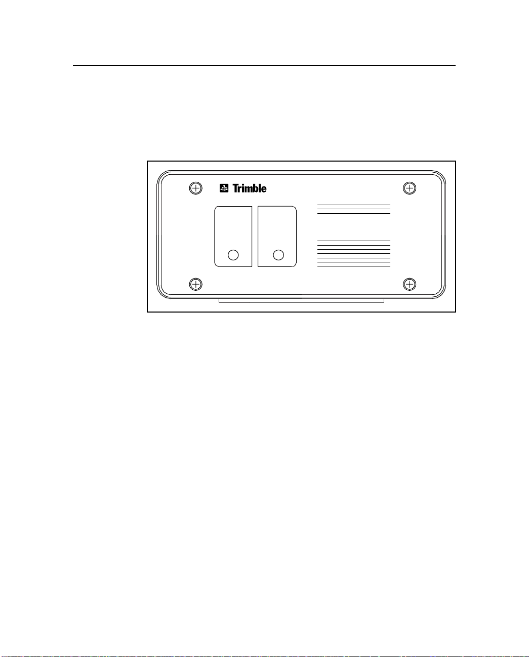
The TRIMTALK 450S radio modem is packaged in a weatherproof,
yellow metal box. The front panel has two indicator lights for power
and data, Figure 1-1.
Figure 1-1 TRIMTALK 450S Front Panel
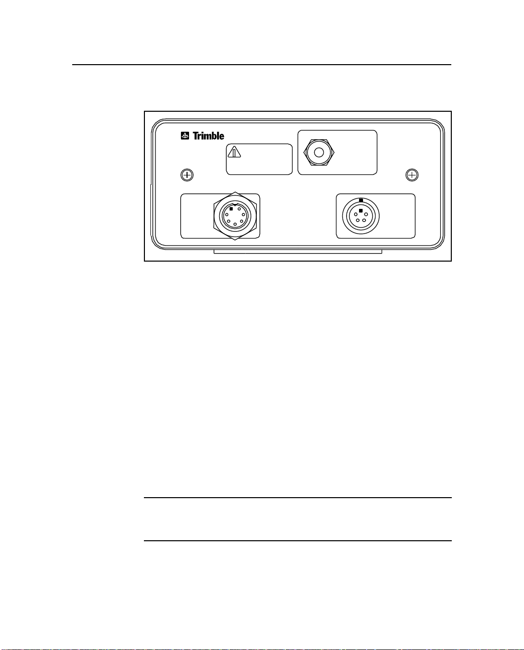
The rear panel has three electrical connectors:
POWER
Overview
TRIMTALK 450S
DATA
•
POWER & I/O connector (five-pin female LEMO)
•
AUX I/O connector (seven-pin male CONXALL)
•
ANTENNA connector (female TNC)
TRIMTALK 450S Operation Manual 1-7
Page 28
Overview
Figure 1-2 shows the rear panel.
WARNING
!
THIS UNIT EMITS
RADIO FREQUENCY ENERGY
SEE MANUAL FOR DETAILS
1
ANTENNA
AUX
I/O
117
SEE OPERATION MANUAL
FOR DETAILED INSTRUCTIONS
& SERVICE INFORMATION
Figure 1-2 TRIMTALK 450S Rear Panel
1.2.1 Controls and Indicators
The TRIMTALK 450S radio modem front panel has two lights. The
DATA light blinks whenever the unit successfully sends or receives a
data packet. The blink is slightly longer when sending a packet than
when receiving one. The POWER light turns on whenever adequate
power is supp li ed t o t he un it . In t he cas e of low power supply vol ta ge
or current, the POWER light may blink or remain off to indicate the
fault condition. Wh en th e POWER light is off, the TRIMTALK 450S
radio modem tries to maintain receiver operation. For example, the
unit may be able to respond to the serial port, or even receive
incoming packets while the POWER light is off due to a partially
discharged battery. However, trying to transmit with a partially
discharged battery results in decreased or zero transmitter power.
5
POWER
& I/O
10-35 VDC
*
Note – Change rechargeable batteries when the POWER light turns
off. Continuing to operate from a discharged battery decreases
battery life.
1-8 TRIMTALK 450S Operation Manual
Page 29

1
1.2.2 Power and I/O Cables
The many possible TRIMTALK 450S configurations use a variety of
cables. In the most common conf igur ation, a TRIMTALK 450S radio
modem receives power and I/O at the POWER & I/O port through a
single LEMO-to-LEMO cable that pl ugs into a Trimble 4700 or 4800
GPS receiver.
To use a Trimble 4800 rover unit with an external TRIMTALK 450S
Rover, use the cable kit available as an accessory. Refer to
Accessories, page 1-5 for more information.
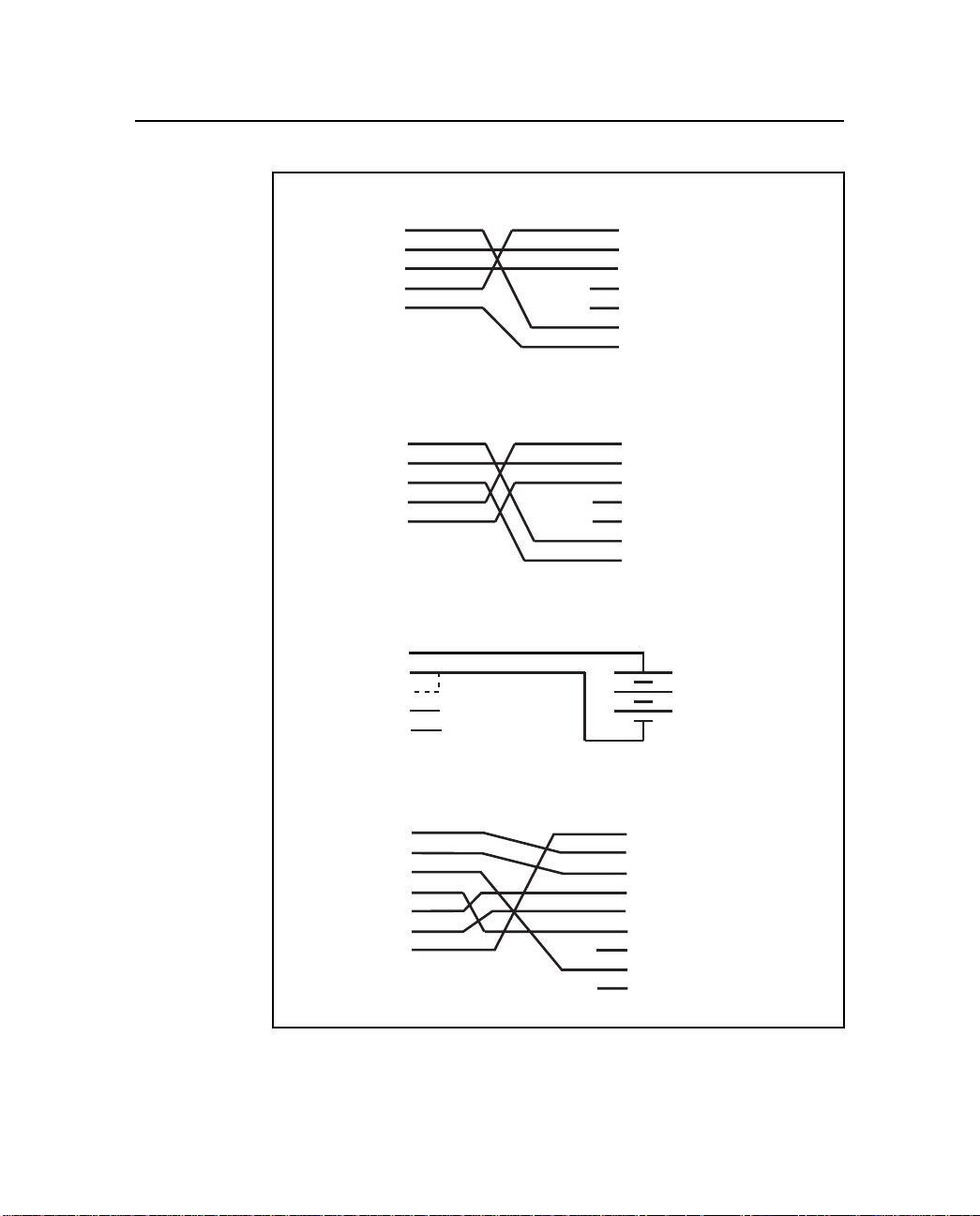
Figure 1-3A shows the wiring for LEMO-to-LEMO cables tha t plug
directly into a Trimble 4700 or 4800 GPS receiver.
Overview
*
*
Note – GPS receivers such as Trimble 4700 and 4800 have a 0-shell
LEMO connector at Port 3. Thus, the data cable used to connect the
radio modem to these receivers must have 1-shell to 0-shell LEMO
connectors.
Figure 1-3B shows the wiring for LEMO-to-LEMO cables tha t plug
directly into a series 4000 GPS receiver. This cable is available as an
accessory. For the 4600 GPS receiver, this cable plugs into the Ycable that comes as part of the 4600 Base as well as Rover Bundles.
Note – Trimble GPS receivers such as Series 4000 and the Site
Surveyor 4400 have a 1-shell LEMO connector at the Power & I/O
port. Thus, the data cable used to connect the radio modems to these
receivers must have 1-shell to 1-shell LEMO connectors.
As an option, the TRIMTALK 450S radio modem can be powered
through the POWER & I/O connector from a battery or other power
supply. The wiring for this configuration is shown in Figure 1-3C.
The dotted line indicates an additional connection that some Trimble
batteries have. This is the us ual way of powering units when they are
used as repeaters.
TRIMTALK 450S Operation Manual 1-9
Page 30
Overview
TRIMTALK
450S
TRIMTALK
450S
LEMO
1
2
3
4
5
LEMO
1
2
3
4
5
P/N 36241-03
P/N 36241-50
A
P/N 21109
P/N 21323
B
N.C.
N.C.
N.C.
N.C.
LEMO
1
2
TRIMBLE 4700 AND 4800
3
GPS RECEIVERS
4
5
6
7
LEMO
1
2
3
GPS RECEIVERS
4
5
6
7
PORT 3
4000, 4400
POWER I/O 2
1
TRIMTALK
450S
LEMO
1
2
3
4
5
P/N 18542
N.C.
N.C.
BATTERY
CLIP
+
BATTERY
C
P/N 21338
N.C.
N.C.
DB9
1
2
3
4
5
6
7
8
9
PC
TRIMTALK
450S
CONXALL
1
2
3
4
5
6
7
D
Figure 1-3 Cables
1-10 TRIMTALK 450S Operation Manual
Page 31

1
If used, the A UX I/ O port on a TRIMTALK 450S can be con nected to
any standard data terminal equipment (DTE), such as a computer,
with a standard 7-pin CONXALL-to-DB9 cable. This cable is
typically used for set up configuration of the unit. The wiring for this
cable is shown in Figure 1-3D. Refer to Chapter 3, Characteristics
and Specifications for connector pinout information.
Overview
M
Warning – Do not use Trimble's dual camcorder battery cable for
connecting power to the radio modem since its 5-pin LEMO pinout is
not compatible with the pinout on the TRIMTALK 450S radio modem.
1.3 Antenna Description
The TRIMTALK 450S radio modem, when purchased as part of the
base, repeater, or rover equipment set, is supplied with an
omnidirectional 5 dB gain antenna, with an interchangeable 0 dB tip.
This antenna can be used with a unit conf igured as a bas e, repeater, or
rover.
The standard 5
in length, nominally, depending on the specific frequency band. With
the interchangeable 0
length, nominally. The antenna attaches to the standard tripod mount
or the frame of Trimble’s kinematic backpack with a 5/8-inch x 11
threads/inch adapter.
Additionally, the TRIMTALK 450S radio modem has three antenna
options to choose from:
•
a 5
repeater operation
dB omnidirectional antenna measur es 99 cm (39 in.)
dB element, the antenna is 47 cm (128.5 in.) in
dB omnidirectional antenna, for permanent base and
•
•
TRIMTALK 450S Operation Manual 1-11
dB directional antenna for base and repeater operation
a 9
dB directional antenna for base and repeater operation
a 12
Page 32

Overview
The optional 5 dB omnidirectional antenna is 127 cm (50 in.) in
length, 2.5
be mounted directly on an antenna mast with the radio modem.
The directional antennas are intended to be bolted to an extended
mast for maximum range at the base or repeater. The 9
antenna is 84
dB directional antenna is 182 .9 cm (72 i n.) in le ngt h and wei ghs 2.25
kg (5.0 lb.). Each antenna comes with an integral antenna cable for
the TRIMTALK 450S radio modem.
cm (1 in.) in diameter, and weighs 1.1 kg (2.4 lbs.). It can
dB directional
cm (33 in.) in length and weighs 0.9 kg (2.0 lb.). T he 12
1
*
Note – Always use the shortest, highest-quality coax cable possible
between the TRIMTALK 450S radio modem and the antenna. Cable
attenuation at the unit’s operating frequency can severely limit the
radio's operational range.
Additional antenna options are possible for special applications. The
major trade-offs are size, weig ht, cost, gain, and country-of-use
regulations. Chapter 3, Characteristics and Specifications describes
the trade-offs involved in selecting antenna types.
1-12 TRIMTALK 450S Operation Manual
Page 33

2 Operation
A TRIMTALK 450S radio modem contains both a data modem and a
radio. It can be used in a variety of configuration s to for m a compl et e
wireless data network. One configuration is as a base radio modem
broadcasting directly to a Trimble 4700 rover or 4800 rover GPS
receiver that contains an internal radio modem. Alternatively, a
TRIMTALK 450S can be used at the base and as a rover. It may also
serve as a repeater in both of the above cases.
Each TRIMTALK 450S radio modem can be used as soon as it is
hooked up. At power-up, the configuration parameters stored in nonvolatile memory initialize the unit for operation. Some of these
parameters must be set to the same values in all the units in use on a
network.
2.1 Configuration
The TRIMTALK 450S radio modem comes from the factory with its
serial I/O port configured for 38400 bps, 8 data bits, odd parity and 1
stop bit. The wireless data link is preconfigured at the factory for
Channel 1, 4800 bps, and Base/Rover mode. These factory default
parameters are stored in nonvolatile memory and serve as the initial
power-up settings for the TRIMTALK 450S radio modem. The unit
retriev es th e parameters stored in non-v ol at ile memor y a t each powerup. The power -up s ettings can be cha nged as of ten as necess ary usi ng
TTSETUP.EXE
the
diskette.
setup utility provided on the TRIMTALK Setup
TRIMTALK 450S Operation Manual 2-1
Page 34

Operation
2
*
Note – Channel 1 refers to the lowest frequency programmed into the
unit. Channel number is used for reference only in TRIMTALK 450S
radio modems. All frequencies in a unit display from lowest to highest
in the
Select a new frequency
2.1.1 Configuring the Serial I/O Port
The TRIMTALK 450S radio modem must be connected to a
computer running Microsoft Windows (3.0 or greater), Windows 95,
or Windows NT to run the TRIMTALK 450S Setup Utility
TTSETUP.EXE
*
(
computer to reconfigure a unit with
help file (
connect the unit to the computer , ins tall the TRIMTALK Setup Utility
under Windows, and set up the serial I/O parameters.
Note – The computer must be able to support a 38400 bps serial port
data rate.
Connecting to a Computer
). Microsoft Windows mus t be installed on the
TTSETUP.HLP
). Perform the following procedures to
list box within the
TTSETUP.EXE
TTSETUP
and its associated
program.
Connect the TRIMTALK 450S radio modem to a COM port on the
computer using one of the following methods:
•
Through a Trimble Office Service Module (OSM)
connect the OSM to the computer with a DB9-DB9 cab le and
connect the OSM cable (LEMO) to the POWER & I/O
connector on the unit.
•
Direct to the Computer
I/O connector with a Conxall -DB9 cable and connect power
to the POWER & I/O connector from an OSM (LEMO) or
battery (LEMO).
2-2 TRIMTALK 450S Operation Manual
- connect the computer to the AUX
-
Page 35
2
Installing the TRIMTALK Setup Utility
See the Microsoft Windows documentation for information on
installing the TRIMTALK 450S Setup Ut ility and an icon for the
program.
Using the TRIMTALK Setup Utility
To use the TRIMTALK Setup Utility:
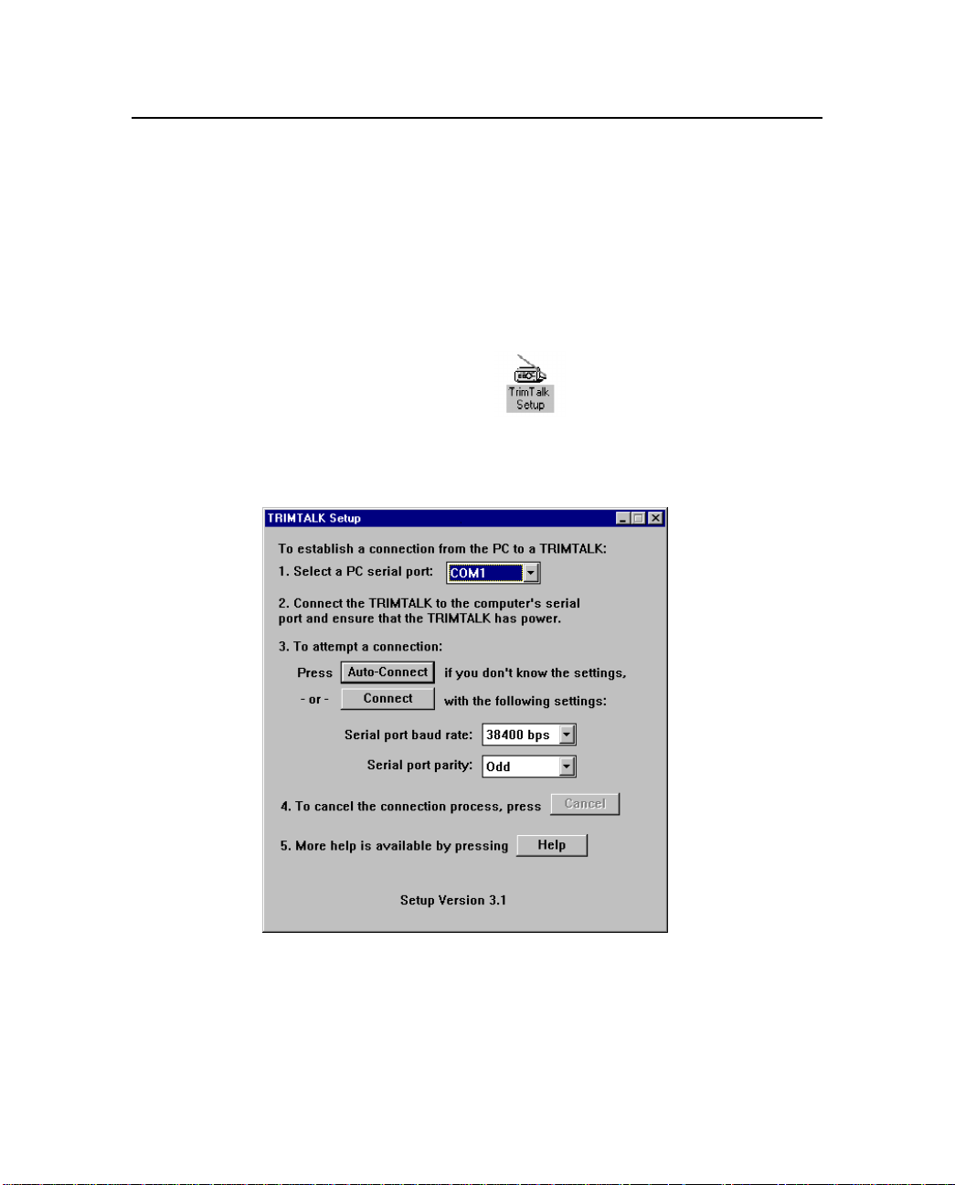
1. Select and open the icon to start the TRIMTALK
Setup Utility. The
Figure 2-1.
TRIMTALK Setup
main window displays,
Operation
Figure 2-1 TRIMTALK Setup Main Window
TRIMTALK 450S Operation Manual 2-3
Page 36

Operation
2
*
Note – Click on HELP to read and print information about the Setup
Utility.
2. Follow the directions in the ma in window to make a logical
connection to the TRIMTALK 450S radio modem.
a. Select the computer serial port (COM port) used in
Step 1.
b. I f you do not know the uni t ’s serial port settings, click on
[Auto-Connect]
c. If you know the serial port baud rate and parity of the
unit, select them in item 3 and click on
.
[Connect]
.
2-4 TRIMTALK 450S Operation Manual
Page 37
2
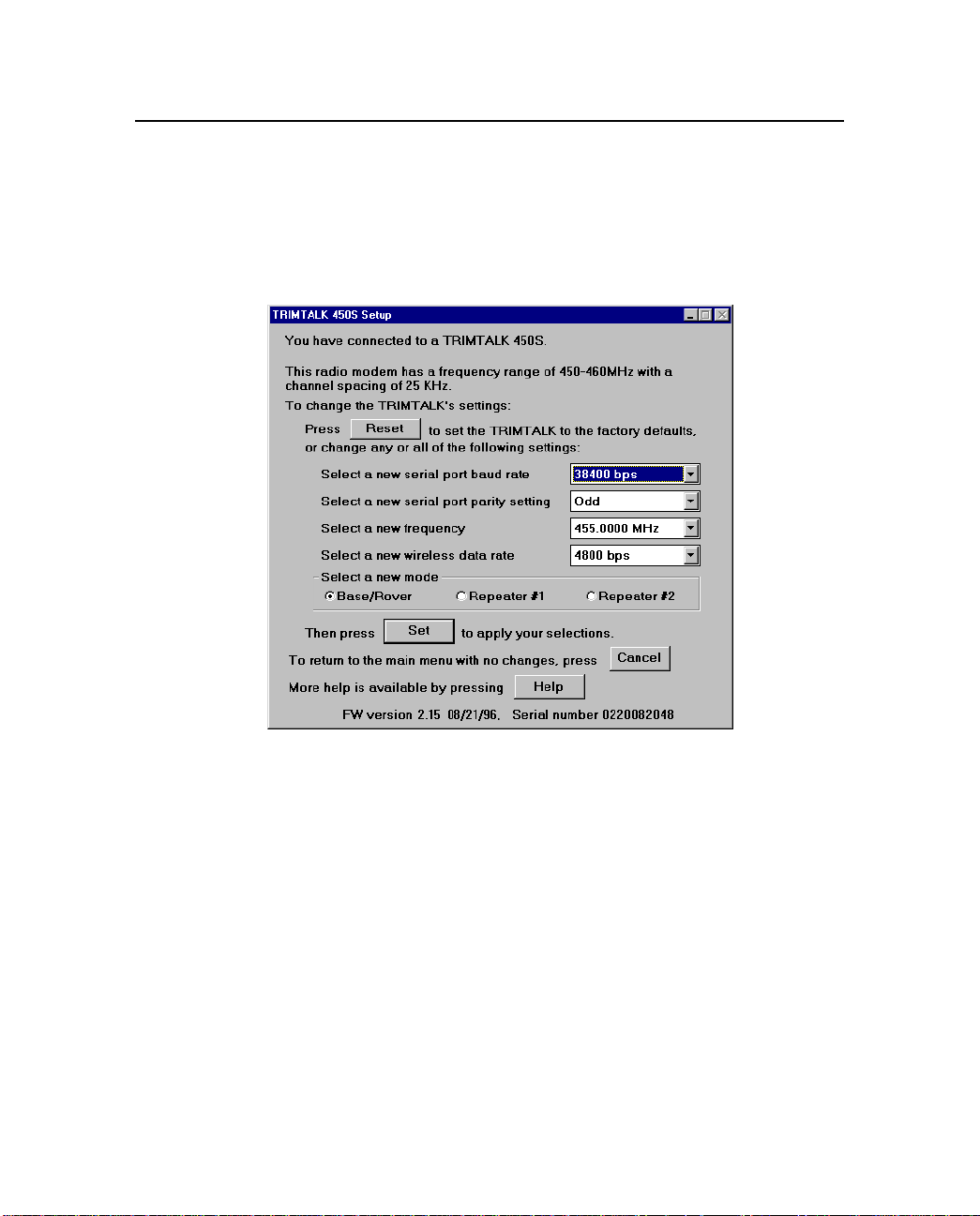
2.1.2 Configuring the Wireless Data Link
Operation
When a successful connection is established, the
window is replaced by the
Figure 2-2.
TRIMTALK 450S Setup
TRIMTALK Setup
window,
Figure 2-2 TRIMTALK 450S Setup Window
Follow the directions in this window to modify the wireless data link
parameters:
•
radio frequency
•
wireless data rate
•
enable the radio modem as a repeater, if required
The serial port baud rate and parity can be changed from this window
if necessary.
TRIMTALK 450S Operation Manual 2-5
Page 38

Operation
2
*
I
*
Note – From the
unit’s operating frequency from the factory pre-programmed list of
available frequencies. See the Updating the List of Available
Frequencies, page 2-7 for inf ormation on reprogramming frequencies.
Perform the following steps to modify the serial port parameters and
wireless data link parameters.
1. Change the serial port baud rate and parity, if necessary.
Caution – Change the unit’s serial port settings only if you plan on
connecting the TRIMT ALK 450S radio modem to a GPS receiver with
serial port settings different than 38400 bps and odd parity.
2. Select the radio fre quency you want from the list of available
frequencies in the
frequencies display fr om lowest to highes t in the list box. The
program cannot accept an invalid setting.
3. Select the wireless data rate from the list i n
wireless dat a rate
invalid setting.
Note – All TRIMT ALK 450S radio modems in a wireless data network
must be configured to the same frequency and wireless data rate.
TRIMTALK 450S Setup
Select a new radio frequency
list windo w. The program canno t acc ept an
window you can select the
list box. All
Select a new
4. Select the radio modem’s mode:
Repeater #2
2-6 TRIMTALK 450S Operation Manual
in the
New Mode
Base/Rover, Repeater #1
list box.
or
Page 39

2
Operation
*
5. Click on
memory. These parameters are retrieved each time the
TRIMTALK 450S radio modem is powered-up.
[Cancel]
window without making any changes.
resets all of the unit's configuration parameters to the
[Reset]
factory defaul ts. The TRIMTALK 450S radio modem’s serial
I/O factory default settings are 38400 bps, 8 data bits, odd
parity and 1 stop bit. The wireless data link factory default
settings are Channel 1, 4800 bps and Base/Rover mode.
Note – If a TRIMTALK 450S radio modem is reset, make sure that its
settings are updated to match the other units in the network before
trying to use it in the network.
to load them into the unit's non-volatile
[Set]
allows you to leave the
TRIMTALK 450S Setup
2.1.3 Updating the List of Available Frequencies
The TRIMTALK 450S radio modem contains a list of up to 20 preprogrammed frequencies stored in non-volatile memory. This list is
preconfigured based on the frequencies requested when the unit was
ordered. All frequencies are sorted from lowest to highest when
viewed in the
Select a new frequency
list box.
Governmental regulations prevent you from programming new
frequencies. Only manufacturers and authorized dealers can update
this frequency list. All frequencies programmed into a TR IMTALK
450S radio modem must comply with the host country regulations.
When you want to change the frequency list (add, delete, or replace
frequencies), t he internal frequency list must be updated. To facilita te
field updates, contact Trimble o r its author ized dealer with the
TRIMTALK 450S radio modem’s serial number and a complete,
updated frequency list to obtain this update. There is a nominal
charge for this service.
TRIMTALK 450S Operation Manual 2-7
Page 40

Operation
2.2 Installation
To use a TRIMTALK 450S radio modem as a base or rover, do the
following:
1. Configure the unit’s serial port and wireless data link
2. Mount the TRIMTALK 450S antenna.
3. Attach the antenna cable to the ANTENNA port on the unit.
4. Connect the POWER & I/O port on the unit to the GPS
5. The TRIMTALK 450S radio modem turns on when the GPS
The TRIMTALK 450S radio modem at the base broadcasts al l dat a it
receives from the base GPS receiver. The TRIMTALK 450S radio
modem used as a rover forwards all data it receives to its rover GPS
receiver. The data is transferre d transparently. Multiple rovers can
receive data from one base.
2
parameters using the TRIMTALK Setup utility.
receiver with the appropriate cable.
receiver is powered up.
2-8 TRIMTALK 450S Operation Manual
Page 41

2
2.2.1 Installation as a Repeater
To increase the range and coverage of the network, data can also be
transmitted from the base to a rover through a repeater. Table 2-1
shows how many repeaters may be used for various wireless data
rates, RTK formats (CMR2, RTCM SC-104 Version 2.1) and RTK
epoch rates (1 Hz, 2 Hz).
Table 2-1 Determining Network Repeater Quantity
Wireless Data
Rate (bps) CMR2 1 Hz CMR2 2 Hz RTCM 2.1 1 Hz
4800 1 0 0
9600 2 1 1
To install a TRIMTALK 450S radio modem as a repeater, do the
following:
1. Configure and enable the unit’s serial port and wireless data
link parameters using the Set Up disk.
2. Mount the TRIMTALK 450S antenna.
Operation
3. Attach the antenna cable to the ANTENNA port on the unit.
4. Connect the POWER & I/O port on the unit to the battery
with the appropriate cable.
TRIMTALK 450S Operation Manual 2-9
Page 42

Operation
2.3 Antenna Installation
Several factors must be considered when installing and locating
TRIMTALK 450S antennas. Place antennas as hi gh as possible abov e
the ground and surrounding obstructions such as trees, trucks,
buildings and hills.
2
*
F
Note – Antenna height is the most important factor in achieving
maximum range with TRIMTALK 450S radio modems. Doubling the
antenna height results in a 40% increase in line-of-sight range.
Objects placed near the antennas, especially metal objects, can
severely limit their efficiency. If an antenna is to be mounted on an
antenna mast, make sure the antenna is mounted so that its radiating
element is completely a bove the top of the mast.
Tip – Keep the radio modem near its antenna. Mount the unit with the
antenna at the top of the mast, rather than running a long length of
coax cable from the unit to an antenna on a mast.
Table 2-2 lists signal losses in dB/100 feet for various types of signal
cable.
Table 2-2 Cable Losses
Cable Type Loss
RG-58 11 dB/100 Feet at 400 MHz
RG-214 5 dB/100 Feet at 400 MHz
*
2-10 TRIMTALK 450S Operation Manual
Note – 3 dB signal loss = 50% power loss = 30% range reduction.
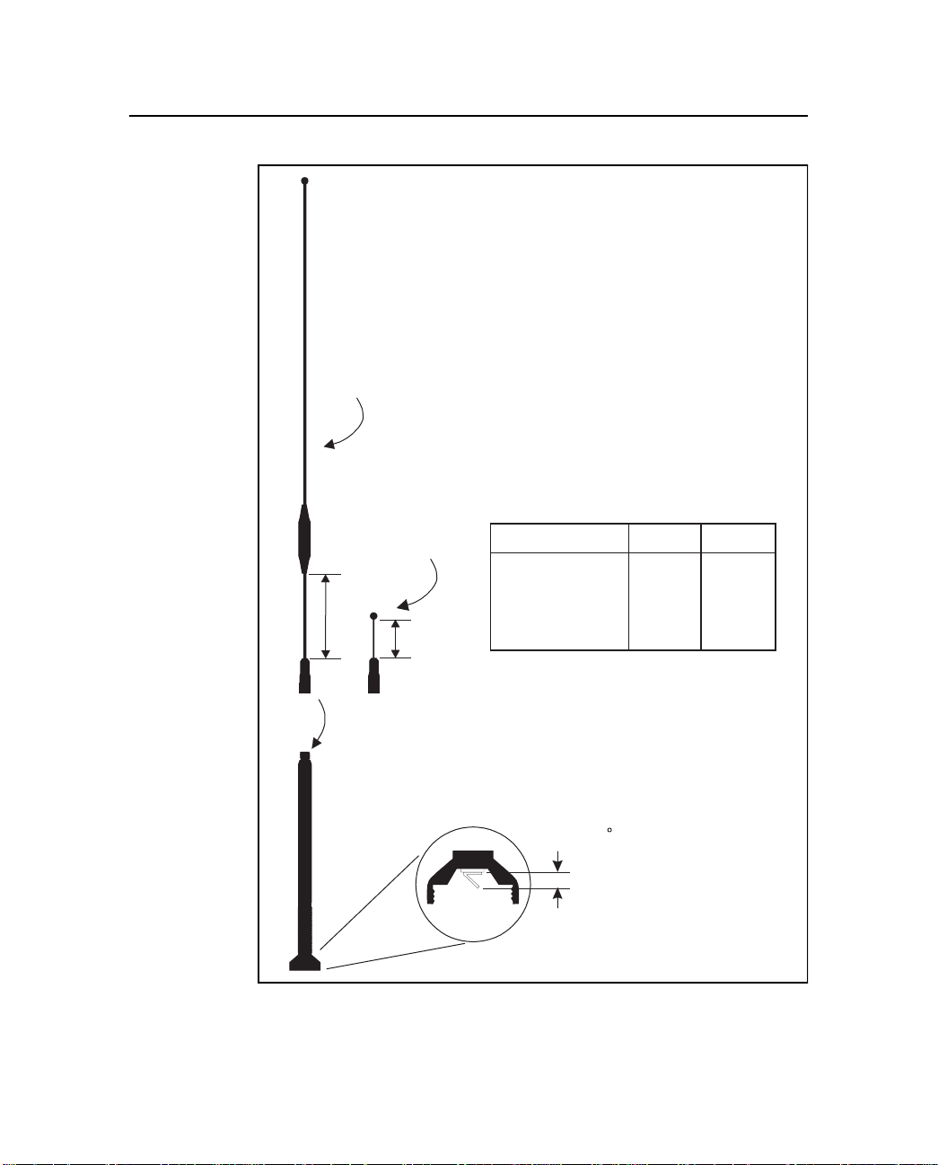
The base of the standard antenna has a spring ta b that must m ake
good contact with the b utton in t he center t op of the an tenna moun t. If
range seems limited to a few hundred feet, check that this tab is
properly aligned and that the gasket has been installed as shown in
Figure 2-3.
Page 43
2
5 dB gain tip
IMPORTANT
Check these lengths and
adjust if necessary by
loosening Allen screw.
Operation
0 dB gain tip
L1
L2
Hand tighten desired antenna
tip onto antenna feed.
Frequency Band L1 L2
430-450 MHz 17.4 cm 12.3 cm
(6.8 in) (4.8 in)
450-470 MHz 16.9 cm 13.3 cm
(6.6 in) (5.2 in)
IMPORTANT:
Check that the contact tab in
the base of the antenna feed
is at a 45 angle.
0.5 to 0.6 cm
(0.2 to 0.25 in.)
Figure 2-3 St andard Omnidirectional Antenna
TRIMTALK 450S Operation Manual 2-11
Page 44
Operation
2
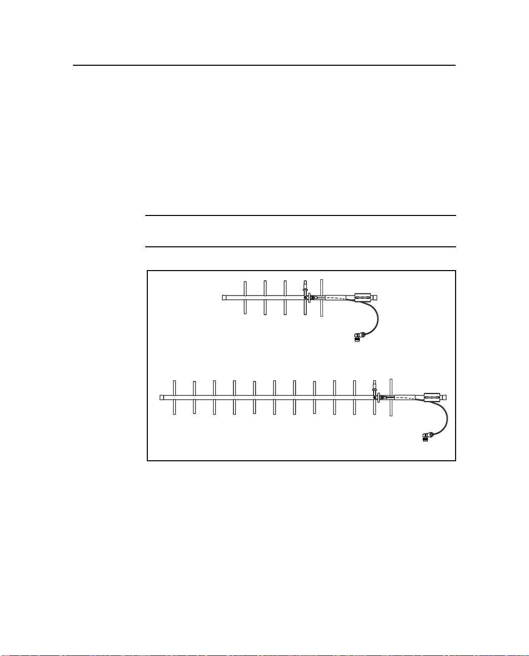
As an option, directional antennas can increase the range in a single
direction, see Figure 2-4. The directional antenna must be pointed in
the direction of the receiving or transmitting antenna to take full
advantage of its antenna design. These antennas are designed to be
mast mounted with the antenna elements vertically oriented. All
directional an tennas in a wir eless data netw or k must be mo unted wit h
their antenna el ement s a ligned in the same orientation. For additional
information refe r to the app lication sh eet supplied wi th the direc tional
antenna.
*
Note – Government regulations may exclude the use of directional
antennas.
9 dB Yagi antenna
12 dB Yagi antenna
Figure 2-4 Di rect ional Antennas
2-12 TRIMTALK 450S Operation Manual
Page 45

3 Characteristics and
Specifications
This appendix briefly summarizes performance characteristics and
specifications that can be expected from a TRIMTALK 450S
network.
3.1 Antenna Gain
TRIMTALK 450S antennas do not increase the energy r adiated by the
radio. They concentrate the energy from the radio in a particular
direction. The degree to which they concentrate radio frequency
energy in an y particul ar directi on is called di recti vi ty and is measu red
in dB, or decibels. The greater the antenna gain in dB, the higher the
directivity and the more the radiated energy from the antenna is
concentrated in some direction.
TRIMTALK 450S Operation Manual 3-1
Page 46
Characteristics and Specifications
3.1.1 Omnidirectional Antennas
An antenna that radiates energy equally in all directions in the
horizontal plane is called omnidirectional. Omnidirectional antennas
radiate an equal amount of energy at every azimuth. However, they
are not omnidirectional in the vertical plane.
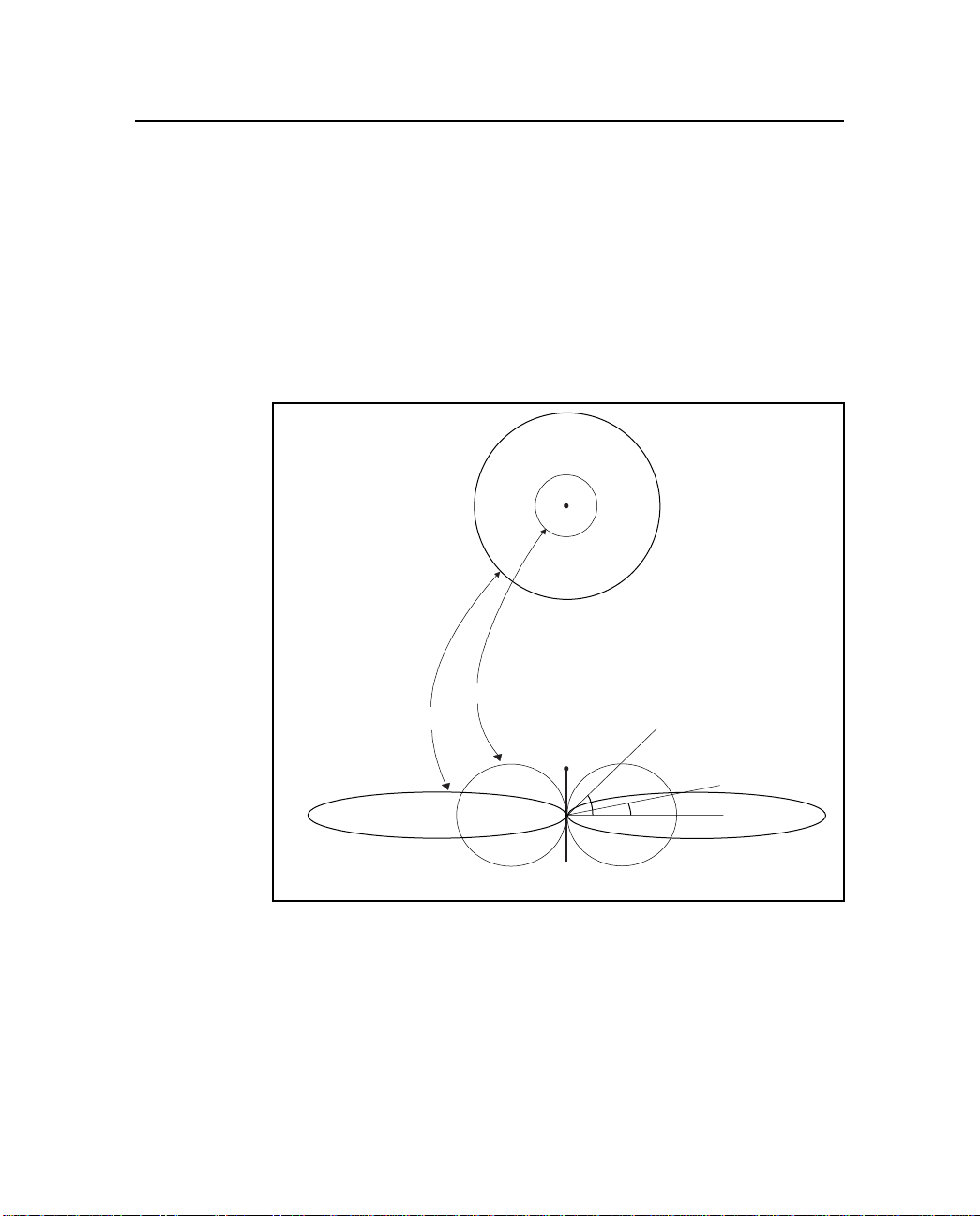
Figure 3-1 shows the radiated energy patterns of the omnidirectional
antennas used with the TRIMTALK 450S radio modem. All
omnidirectional antennas must be oriented vertically when used.
top view
3
Azimuth
0 dB
5 dB
ground level
view
Elevation
45˚
12˚
Figure 3-1 Omnidirectional Antenna Gain Patterns
3-2 TRIMTALK 450S Operation Manual
Page 47

3
The top view shows radiated energy patterns in the horizontal, or
azimuth plane of the antennas, the plane that perpendicularly bisects
the length of the antenna. For omnidirectional antennas, all azimuths
receive equal energy, but the 5 dB antenna radiates almost four times
more power in the horizontal plane than does the 0 dB antenna. In an
open field, four times more power approximately doubles the range.
The bottom view shows radiated energy patterns in the vertical, or
elevation, plane of the antennas. Much of the energy from the 5 dB
antenna is concentrated in elevation to within ±12° of horizontal. A
rover antenna within this sector receives stronger signals from a 5 dB
antenna. However, at angles greater than 12° from horizontal, the 0
dB gain antenna radiates more energy.
Antenna gain has exactly the same effect on signal reception as it
does on signal transmission. A high gain rover antenna can increase
range performance as long as it is oriented correctly with respect to
the transmit antenna. For high gain antennas, this means keeping the
antenna element vertical and at the same elevation as the transmitting
antenna. Otherwise, it may be better to use an antenna with less gain.
Characteristics and Specifications
TRIMTALK 450S Operation Manual 3-3
Page 48
Characteristics and Specifications
3.1.2 Directional Antennas
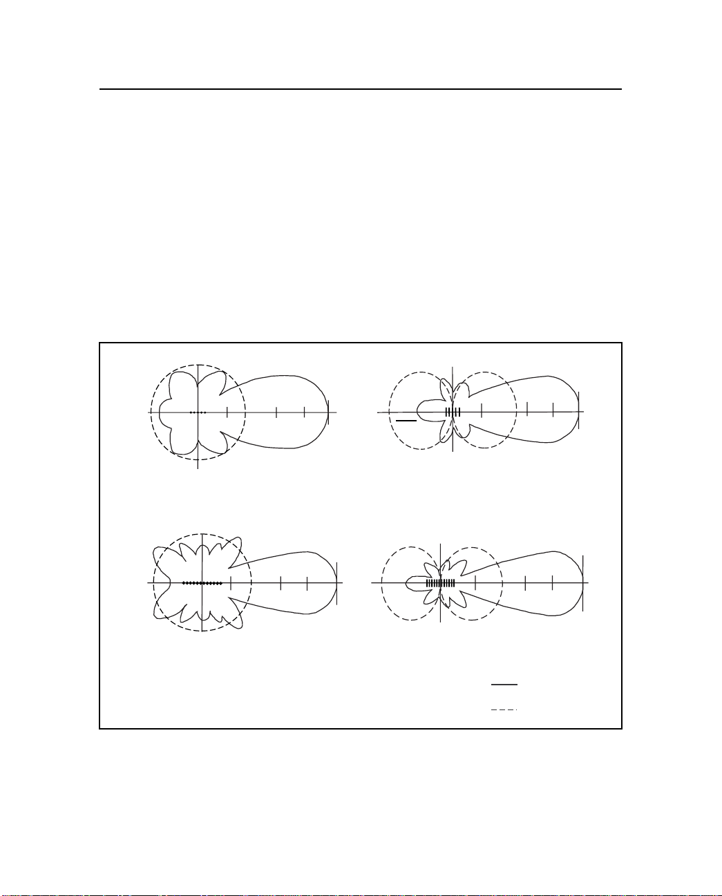
Two directional antennas, a 9 dB Yagi and a 12 dB Yagi antenna, are
available as options, dependent on applicable governmental
regulations. Figure 3-2 shows the radiated energy patterns of the
directional antennas that can be used with the TRIMTALK 450S
radio modem. The solid line depicts the directional antennas as
compared with the dashed lines representing the omnidirectional
antennas. In princi ple, th e direct ional ant enna is sim ilar t o a flashl ight
while an omnidirectional antenna is similar to a light bulb. The
flashlight concentrates light into a narrow beam while a light bulb
illuminates evenly, but usually not as far as the flashlight.
3
90
180
horizontal pattern
-11 dB +1 dB +5 dB +9 dB
270
180
0
vertical pattern
9 dB directional antenna patterns
90
180
180
horizontal pattern
270
-8 dB
+2 dB +8 dB +12 dB
0
270
vertical pattern
12 dB directional antenna patterns
Figure 3-2 Directional Antenna Gain Patterns
90
-11 dB +1 dB +5 dB +9 dB
270
90
-8 dB +2 dB +8 dB +12 dB
directional
Antenna
omnidirectional
Antenna
0
0
3-4 TRIMTALK 450S Operation Manual
Page 49

3
A Yagi antenna focuse s the radiat ed power into a di rectional
transmission used for straight lines (±20° for the 9 dB directional
antenna or ±17° for the 12 dB directional antenna). Since most of the
power is focused in one direction, a Yagi antenna transmits further in
this direction than an omnidirectional antenna.
The line-of-sight range increase for a unit using the 9 dB directional
antenna is about 1.6 times that obtained using the 5 dB
omnidirectional antenna. The line-of-sight range increase for a unit
using the 12 dB dire ctiona l a ntenna is abou t tw ice t hat obt ained usi ng
the 5 dB omnidirectional antenna. TRIMTALK 450S radio modem
range varies depending on line-of-sight visibility, blockage or
absorption by vegetation, antenna pointing errors, antenna height,
terrain anomalies, and local weather conditions.
Characteristics and Specifications
*
Note – Directional antennas are useful for working in a straight line
such as along railroad tracks or roads, or where repeaters are
inconvenient or impossible such as crossing lakes, or between
mountains. Directional antennas have a limited ability to receive radio
signals from any direction other than the direction in which they are
pointed. For omnidirectional situations, the 0
omnidirectional antennas are recommended.
Because of the trade-off between gain and vertical coverage, the
TRIMTALK 450S radio modem is shipped wit h a 0 dB and/or a 5 dB
antenna, dependent on your local government regulations.
dB or 5 dB
TRIMTALK 450S Operation Manual 3-5
Page 50
Characteristics and Specifications
3.2 Point-To-Point Link
The point-to-point link performance is a function of the radio
frequency path from one TRIMTALK 450S radio modem to another.
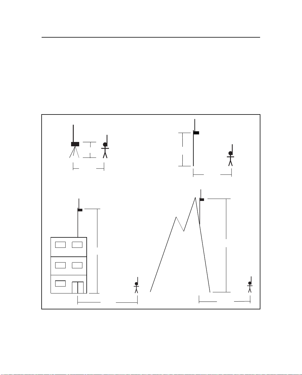
This path includes the coaxial cables and antennas. Figure 3-3 shows
some typical range limits that can be encountered when using
TRIMTALK 450S links in open areas with minimal local radio
interference.
3
2 m
4 km
20 m
15 km
10 m
7 km
Figure 3-3 Typical Range Limits Without Obstructions
100 m
20 km
3-6 TRIMTALK 450S Operation Manual
Page 51

3
Many factors can r educe the ope rationa l range of a TRIMTALK 450S
link: multipath fading, interference, an d shadowing. They are
unpredictable. Empirical testing has yielded performance curves that
can be used to estimate performance in a probabilistic sense, but
performance in specific situations cannot be predicted.
Multipath fading results when multiple reflected copies of the
transmitted waveform destructively interfere at the receive antenna.
This problem can be so intense in an urban environment that the
TRIMTALK 450S link is limited to several hundred feet. However,
this type of fading is usually localized to very small areas. Moving an
antenna a few inches can sometimes overcome this problem.
Interference with the TRIMTALK 450S link can be caused by other
transmitters in the same frequency band. If interference is suspected,
the TRIMTALK 450S radio modems can be set to another frequency
channel if one is available. See Configuration, page 2-1.
Shadowing results when the lin k loses line-of-sight (LOS ) due to an
obstruction such as a building, hill, or trees. A TRIMTALK 450S
radio modem occasionall y recei v es with out LOS becau se radio waves
diffract ar ound some obst ructi ons and tr a v el through ot hers. The only
way to know where a link will wo rk is to try it.
Characteristics and Specifications
*
TRIMTALK 450S Operation Manual 3-7
Note – Antenna height is the single most important factor you can use
to increase link distance. Always place base and repeater antennas
as high as possible above surrounding obstructions. Use hill tops and
antenna masts wherever practical.
Page 52

Characteristics and Specifications
3.2.1 Frequency Band and Channel Selection
The TRIMTALK 450S radio modem operates in one the following
frequency bands:
•
430 to 440 MHz
•
440 to 450 MHz
•
450 to 460 MHz
•
460 to 470 MHz.
The unit only operates in one of these bands, not across bands. If
multiple band coverage is needed, multiple TRIMTALK 450S radio
modems are required, with each unit covering one of the bands.
The TRIMTALK 450S radio modem stores up to 20 factory preprogrammed frequencies, and operates on one of these frequencies,
depending on which is selecte d. All 20 frequencies m ust reside with in
one of the above frequency bands. These freque nci es a re pre set at the
factory.
In addition, TRIMTALK 450S radio modems are available in two
different channel spacing configurations: 12.5 kHz and 25 kHz.
Channel spacing refers to the minimum separation, in Hz, between
two adjacent frequencies and can be viewed as the tuning resolution
of the radio modem. Channel spacing is dependent on local
government regulations.
3
3-8 TRIMTALK 450S Operation Manual
Page 53

3
3.2.2 Wireless Data Rate
The wireless data rate is the speed, in bits per second (bps) , at which
the base unit transmits data to the rover unit. Table 3-1 lists the rates
that are available depending on the channel spacing of the
TRIMTALK 450S radio modem.
Table 3-1 Wireless Data Rates
Channel Spacing Data Link Rate (bps)
12.5 kHz 1200, 2400, 4800
25 kHz 1200, 2400, 4800, 9600
Although a higher wireless data rate transfers data packets faster, it
may make the da ta link more vulnerable to external interference and/
or other signal propagation effects that reduce the operational range
of the link.
3.2.3 RF Output Power
Dependent on governmental regulations, the RF output power of the
transmitter can be increased to higher levels by using an external
power amplifier. A higher RF output power typically yields a longer
operational range. Contact your Trimble dealer regarding
recommended power amplifier models, regulations, and restrictions
on operation in the country or area where you are using the
TRIMTALK 450S radio modem.
Characteristics and Specifications
TRIMTALK 450S Operation Manual 3-9
Page 54

Characteristics and Specifications
3.3 Electrical Interface
The TRIMTALK 450S rear panel has three connectors:
•
POWER & I/O
•
AUX I/O
•
ANTENNA
The POWER & I/O connector is a five-pin female LEMO connector.
Its pinout matches the Port 3 connector on the 4700 and 4800 GPS
receivers. The names of the RXD and TXD pins, as shown in
Table 3-2, have been switched f rom the GPS receiver convention
since the TRIMTALK 450S uses signal naming for data
communication equipment (DCE). See Figure 1-3 for further details.
For office use, a Trimble OSM II can connect directly to this port for
power and I/O.
Table 3-2 POWER I/O Connector Pinout
Pin # Name I/O Description
1 BAT 10-to-35 volt DC source
2 BAT RTN Power ground
3 TXD I RS-232 data from terminal to
4 SGND RS-232 signal ground
5 RXD O RS-232 data from TRIMT ALK 450S to
3
TRIMTALK 450S
terminal
3-10 TRIMTALK 450S Operation Manual
Page 55

3
Characteristics and Specifications
The AUX I/O connector is a 7-pin male CONXALL connector.
Table 3-3 identifies the signals on this port. All signals are RS-232
compatible. RXD on this connector always outputs the same data as
the RXD pin on the POWER I/O connector.
Table 3-3 AUX I/O Connector Pinout
Pin # Name I/O Description
1 RXD O Data from
2 TXD I Data from terminal to TRIMTALK 450S
3 CTS O TRIMTALK 450S is ready to receive data
from terminal
4 DSR O TRIMTALK 450S is on
5 DTR I Terminal is ready to receive data from
TRIMTALK 450S
6 SGND Signal ground
7 DCD O TRIMTALK 450S has established
connection with a remote TRIMTALK
450S
TRIMTALK
450S to terminal
The antenna connector on the TRIMTALK 450S radio modem is a
female TNC. The antenna should be connected to this port with the
shortest, highest-quality coax cable possible.
*
TRIMTALK 450S Operation Manual 3-11
Note – Long antenna cables seriously degrade the range of the
wireless data network.
Page 56

Characteristics and Specifications
3.3.1 Power Consumption
When not transmitting, th e TRIMT ALK 450S radio modem dissipates
less than 1 watt. When transmitting a packet at 4800 bps, the unit
draws less than 4 watts for about 400 msec. Average power
consumption for a unit is given by:
= 1 + (packets per second)*1.2 watts
P
AVG
Table 3-4 lists approximate power consumptio n values for the
TRIMTALK 450S radio modem. Values are listed for base, repeater,
and rover configurations by different wireless data rates, RTK
formats, and RTK epoch rates. As the values in the table indicate,
power consumption v a ries wi th the selec ted wirel ess dat a rat e and t he
broadcast information content. In this case, CMR2 versus
RTCM SC-104 Version 2.1 RTK packets at 1 Hz versus 2 Hz RTK
epoch rates.
Table 3-4 Power Consumption Values (Appr oximate)
3
Configuration Wireless
Data Rate
(bps)
Base 4800 2.2 W 3.4 W 4.0 W
9600 1.6 W 2.2 W 2.8 W
Repeater 4800 2.2 W 3.4W 4.0 W
9600 1.6 W 2.2 W 2.8 W
Rover 4800 1.0 W 1.0 W 1.0 W
9600 1.0 W 1.0 W 1.0 W
3-12 TRIMTALK 450S Operation Manual
CMR2
1 Hz
CMR2
2 Hz
RTCM 2.1
1 Hz
Page 57

3
3.4 Specifications
The following tables contain information on the TRIMTALK 450S
radio modem, antenna, and frequency.
Table 3-5 Radio Modem Physical Specifications
Parameter Specification
Size 14.3 cm (5 5/8 in.) Wide
Weight 0.95 kg (2.1 lbs)
Power Input 10 V to 35 V DC
Connectors Power & I/O 5-pin female LEMO (supports
Indicators Power LED with good, low, and no-power modes
Temperature Operating –20° to +55° C (–4 ° to +131° F)
Humidity 100% sealed; rain and splash proof
Characteristics and Specifications
19.0 cm (7 1/2 in.) Deep
6.7 cm (2 5/8 in.) High
RXD, TXD and SGND)
Auxiliary I/O 7-pin male CONXALL
RS-232C (supports RXD, TXD,
SGND, DTR, DSR,DCD, and
CTS)
Antenna TNC female
Data LED for valid transmit and receive packets
Storage –30 ° to +70° C (–22° to +158° F)
Table 3-6 Antenna Physical Specifications
Type Length (typical) Weight
Standard 0 dB omni 47 cm (18.5 in.) 0.45 kg (1.0 lb.)
Standard 5 dB omni 99 cm (39 in.) 0.45 kg (1.0 lb.)
Optional 5 dB omni 127 cm (50 in.) 1.1 kg (2.5 lb.)
9 dB directional 84 cm (33 in.) 0.9 kg (2.0 lb.)
12 dB directional 183 cm (72 in.) 2.3 kg (5.0 lb.)
TRIMTALK 450S Operation Manual 3-13
Page 58

Characteristics and Specifications
Table 3-7 Performance Specifications (Typical)
Transmit power <0.5 watts
Wireless data
rate
Frequency
bands
Channel spacing 12.5 kHz and 25 kHz
Number of
channels
RF Modulation
format
Range Optimal: 10 km, line-of-sight
Power
consumption
Battery life Transmitting: 12 hours on one 6 AH battery;
Serial port One set of RS-232 signals available on two
1. 9600 bps is not available for units with 12.5 kHz channel spacing.
1200, 2400, 4800, and 9600 bps
1
430-440 MHz, 440-450 MHz, 450-460 MHz,
or 460-470 MHz. Only one band per radio
modem
Up to 20 factory pre-programmed
frequencies, internally stored.
2
Gaussian Minimum Shift Keying (GMSK) at
4800 and 9600 bps. MSK at 1200 and 2400
bps.
Typical: 3 to 5 km
Varies with terrain and operational conditions
Up to 2 repeaters may be used to extend
range
Base/repeater: 3 W, typical
Rover: 1 W, typical
typical at 20°C (70°F)
Receiving: 12 hours on one 2.3 AH
camcorder battery; typical at 20°C (70°F)
connectors. Data is 8 bits with selectable
parity and 1 stop bit. Supported data rates
include 300, 600, 1200, 2400, 9600, 19200
and 38400 bps.
3
2. Select only one freq uency for use a t any ti me. U se the s ame freque ncy
for all radio modems in the same wireless data network.
3-14 TRIMTALK 450S Operation Manual
Page 59

A Equipment Sets and
Accessories
Table lists the items that are supplied with the standard equipment
sets. The Equipment Set column indicates which equipment set
contains the item.
Table A-1 Equipment Sets
Part
Description
TRIMTALK 450S Radio Modem 28876-00 Base, Rover, Repeater
Standard Antenna (0 DB, 5 DB), 430-450
MHz
Standard Antenna (0DB, 5DB), 450-470
MHz
Tripod Mount with Antenna Cable 25945-10 Base, Repeater
Antenna Mount with 5 foot Cable 22720 Rover only
50-foot Po wer and I/O cable (1 shell-0 shell) 36241-50 Base only
3-foot Power and I/O cable (1 shell-0 shell) 36241-03 Rover only
Configuration Cable, 6 foot TRIMTALK - PC 21338 Base, Rover, Repeater
6 AH Battery with Cable 13543-00 Repeater only
Adapter cable (1 Shell Female - 0 Shell
Male)
TRIMTALK Set Up Program V3.1 36321-01 Base, Rover, Repeater
Manual 28964-00 Base, Rover, Repeater
Number E q uipment Set
24253-44 Base, Rover, Repeater
24253-46 Base, Rover, Repeater
32959 Repeater only
TRIMTALK 450S Operation Manual A-1
Page 60

Equipment Sets and Accessories
Table lists the additional accessories as described in Accessories,
page 1-5.
Table A-2 Accessories
Description Part Number
5 dB Omnidirectional Base Antenna, 430-450 MHz 24251-44
5 dB Omnidirectional Base Antenna, 450-470 MHz 24251-46
9 dB Directional Antenna (Base/repeater Operation), 450-470 MHz 30600-46
12 dB Directional Antenna (Base/repeater Operation), 450-470 MHz 30601-46
50-foot Po wer & I/O Cable (1 shell - 1 shell) 21323
3-foot Po wer & I/O Cable (1 shell - 1 shell) 21109
50-foot Power & I/O Extension Cable 21257
Office Supply Module II 23001-00
PC to OSM Cable (DB9 to DB9) 14284
10 AH Battery/Case/Cable 13542-00
Charger for 6AH Battery 32595-00
Adapter Cable 32959
Cable Kit for use with 4800 Rover and External Radio Modem 37745-00
Li-Ion PowerLITE Battery Cable 33914-00
Li-Ion PowerLITE Batteries (3 each) 31030-00
Camcorder Battery Cable (Single Head ) 33928
Camcorder Battery 17466
A
A-2 TRIMTALK 450S Operation Manual
Page 61

B Regulations
This appendix describes the operator’s permit, which is obtained by
the user, and the type approval, which is granted to the manufacturer.
B.1 Operator’s Permit or License
Before operating a TRIMTALK 450S radio modem, authorization or
a license to operate the unit is required in your country. Although the
rules and regulations that apply to this radio modem are different
from country to country, the technical specifications listed in this
manual are standard. Numerous changes to regulations are common,
which is why many users are unaware of the current regulations.
Obtaining an operator’s permit or license for the unit(s) for the
location or country of operation is your responsibility.
*
*
TRIMTALK 450S Operation Manual B-1
Note – For Canadian use, users of this equipment must contact
Industrie Canada and receive a license before operating this unit.
Note – This device complies with Part 15 of the FCC Rules.
Operation is subject to the condition that this device does not cause
harmful interference.
Page 62

Regulations
B.2 Type Approval
Type Approval, or acceptance, covers technical parameters of the
equipment related to emissions that can cause interference. Type
Approval is granted to the manufacturer of the transmission
equipment, independent from the operation or licensing of the units.
(Licensing or application for operation is the responsibility of the
user.) Some countries have unique technical requirements for
operation in the TRIMTALK 450S frequency bands. To comply with
those requirements, Trimble may have modified your equipment in
order to be granted Type Approval. Unauthorized modification to the
units voids the Type Approval, the warranty and the operational
license of the equipment.
B
I
Caution – Changes or modifications to this equipment not approved,
in writing, by Trimble Navigation Limited voids your authority to
operate the equipment.
B-2 TRIMTALK 450S Operation Manual
Page 63

Index
Numerics
1 stop bit 2-1
38400 bps 2-1
8 data bits 2-1
A
accessories 1-4, 1-5
antenna iii, 2-10
0 dB 3-3
5 dB 3-3
description 1-11
installation 2-10
obstructions 2-10
omnidirectional 3-2
antenna gain 3-1
audience xv
B
battery 1-9
C
cable
7-pin CONXALL-to-DB9 1-11
LEMO-to-LEMO 1-9
cautions xix
characteristics 3-1
COM port 2-2
configuration
TRIMTALK 450S 2-1
Configuring the Wireless Data Link 2-5
connector
ANTENNA 1-7
AUX I/O 1-7, 3-11
POWER & I/O 3-10
POWER I/O 1-7
connector pinout
AUX I/O 3-11
POWER I/O 3-10
controls 1-8
copyrights ii
D
DATA li ght 1-8
data modem 2-1
description
antenna 1-11
DGPS 1-1
differential GPS
DGPS 1-1
directional antennas 2-12
disclaimer of warranty iii
TRIMTALK 450S Operation Manual Index-1
Page 64

Index
document conventions xviii
E
electrical interface 3-10
Equipment Sets and Accessories 1-4
F
features 1-3
I
I/O cables 1-9
indicators 1-8
installation
antenna 2-10
repeater 2-9
TRIMTALK 450S 2-8
interference 3-7
L
limitation of liability iv
limited warranty
firmware iv
hardware v
software iv
line-of-sight
LOS 1-1
LOS 1-1, 3-7
M
multipath fading 3-7
N
network
TRIMTALK 450S 1-1
notes xix
O
odd parity 2-1
operator’s permit B-1
options 1-3
organization xv
OSM 2-2, 3-10
overview 1-1
P
PC 2-2
physical specifications
TRIMTALK 450S 3-13
point-to-point li nk 3-6
power cables 1-9
POWER light 1-8
power supply 1-9
preface xv
R
radio 2-1
radio link 1-2
range limits 3-6
reader comment form xviii
real-time kinematic
RTK 1-1
regulations B-1
related information xvi
Index-2 TRIMTALK 450S Operation Manual
Page 65

Index
update notes xvi
repeater 1-1
installation 2-9
revision notice iii
RF energy iii
RS-232 3-11
RTK 1-1
S
safety iii
Safety Levels with Respect to Human
Exposure to Radio Frequency
Electromagnetic Fields, 300 kHz to
100 GHz iii
scope xv
serial port
asynchronous 1-3
Setup Window 2-5
shadowing 3-7
specifications 3-1
TRIMTALK 450S Front Panel 1-7
TRIMTALK S etup main window 2-3
TRIMTALK Setup Utility 2-2
Type Approval B-2
U
update notes xvi
Updating the List of Available
Frequencies 2-7
W
warnings xix
T
TAC xvii
Technical Assistance xvii
Technical Assistance Center
TAC xvii
tips xix
trademarks iii
TRIMTALK 450S
configuration 2-1
description 1-7
installation 2-8
network 1-1, 3-1
operation 2-1
TRIMTALK 450S Operation Manual Index-3
Page 66

Index
Index-4 TRIMTALK 450S Operation Manual
Page 67

Reader Comment Form
TRIMTALK 450S Operation Manual November 1998
P/N: 28964-00 Revision B
We appreciate your comments and suggestions for improving this publication.
Contributors of particularly helpful evaluations will receive a thank-you gift.
I use the following Trimble product________________________________________________
for__________________________________________________________________________
Please circle a response for each of the statements below:
1 = Strongly Agree 2 = Agree 3 = Neutral 4 = Disagree 5 = Strongly Disagree
The manual is well organized. 12345
I can find the information I want. 12345
The information in the manual is accurate. 12345
I can easily understand the instructions. 12345
The manual contains enough examples. 12345
The examples are appropriate and helpful. 12345
The layout and format are attractive and useful. 12345
The illustrations are clear and helpful. 12345
The manual is: too long just right too short
Please answer the following questions:
Which sections do you use the most? ______________________________________________
What do you like best about the manual? ___________________________________________
____________________________________________________________________________
What do you like least about the manual? ___________________________________________
____________________________________________________________________________
Optional
Name _______________________________________________________________________
Company ____________________________________________________________________
Address______________________________________________________________________
____________________________________________________________________________
Telephone____________________________________________________________________
FAX ________________________________________________________________________
Please mail to the local office listed on the back cover, or to Trimble Navigation
Limited, 645 North Mary Avenue, Post Office Box 3642, Sunnyvale, CA 94088-
3642. All comments and suggestions become the property of Trimbl e
Navigation Limited.
Page 68

 Loading...