

Page 1

Revision B
Trimble SPS785
GNSS Receiver
User Guide
TRANSFORMING THE WAY THE WORLD WORKS
Ve
rsion 2
M
ay 2019
Page 2

gal Notices
Le
©2019 Trimble Inc. All rights reserved.
All product and brand names mentioned in this
publication are trademarks of their respective holders.
SPS785 User Guide, Rev. B, May 2019.
Limited Warranty Terms and Conditions
Product Limited Warranty. Subject to the terms and
conditions set forth herein, Trimble Inc. (“Trimble”)
warrants that for a period of (1) year from date of
purchase this product (the “Product”) will substantially conform to our publicly available specifications for the Product and that the hardware and any
storage media components of the Product will be
substantially free from defects in materials and
workmanship.
Product Software. Product software, whether built
into hardware circuitry as firmware, provided as a
standalone computer software product, embedded
in flash memory, or stored on magnetic or other media, is licensed solely for use with or as an integral
part of the Product and is not sold. The terms of the
end user license agreement govern the use of the
Product Software, including any differing limited
warranty terms, exclusions and limitations, which
shall control over the terms and conditions set forth
in the limited Product warranty.
Warranty Remedies. If the product fails during the
warranty period for reasons covered by this limited
warranty and you notify us of such failure during
the warranty period, we will repair OR replace the
nonconforming product with new, equivalent to
new, or reconditioned parts or product, OR refund
the product purchase price paid by you, at our option, upon your return of the product in accordance
with our product return procedures then in effect.
Notices
This device complies with RF radiation exposure requirements set forth for the general population (uncontrolled exposure).
This device must not be collocated or operated in
conjunction with any other antenna or transmitter
and it must be installed to provide the following
separation distances from all persons:
– 45 cm for SPS785 with UHF radio
– 20 cm for SPS785 without UHF radio
USA
Class B Statement - Notice to Users. This equipment has been tested and found to comply with the
limits for a Class B digital device, pursuant to Part
15 of the FCC Rules. These limits are designed to
provide reasonable protection against harmful interference in a residential installation. This equipment generates, uses and can radiate radio
frequency energy and, if not installed and used in
accordance with the instructions, may cause harmful interference to radio communication. However,
there is no guarantee that interference will not occur in a particular installation. If this equipment
does cause harmful interference to radio or television reception, which can be determined by turning
the equipment off and on, the user is encouraged
to try to correct the interference by one or more of
the following measures:
• Reorient or relocate the receiving antenna.
• Increase the separation between the equipment
and the receiver.
• Connect the equipment into an outlet on a circuit different from that to which the receiver is
connected.
• Consult the dealer or an experienced radio/TV
technician for help.
If the SPS785 is used with UHF radio in the US,
the following modules are available:
• 400MHz: Trimble part number 89941-01
• 900MHz: Trimble part number 117243-90
Changes or modifications not expressly approved by
the manufacturer or registrant of this equipment
can void your authority to operate this equipment
under Federal Communications Commission rules.
Supplier’s Declaration of Conformity
declare under sole responsibility that the product:
complies with Part 15 of FCC Rules.
Operation is subject to the following two
(1) this device may not cause harmful interference,
(2) and this device must accept any interference
received, including interference that may cause
Trimble Inc.
10368 Westmoor Dr.
Westminster, CO 80021
Canada
The digital apparatus does not exceed the Class B
limits for radio noise emissions from digital apparatus as set out in the radio interference regulations
of the Canadian Department of Communications.
This device contains licence-exempt transmitter(s)/
receiver(s) that comply with Innovation, Science
and Economic Development Canada’s licence-exempt RSS(s). Operation is subject to the following
two conditions:
(1) This device may not cause interference.
(2) This device must accept any interference, including interference that may cause undesired operation of the device.
Le présent appareil numérique n’émet pas de
bruits radioélectriques dépassant les limites
applicables aux appareils numériques de Classe B
prescrites dans le règlement sur le brouillage
radioélectrique édicté par le Ministère des
Communications du Canada.
Le présent appareil est conforme aux CNR d'Industrie Canada applicables aux appareils radio
exempts de licence. L'exploitation est autorisée aux
deux conditions suivantes:
(1) l'appareil ne doit pas produire de brouillage, et
(2) l'utilisateur de l'appareil doit accepter tout
brouillage radioélectrique subi, même si le brouillage est susceptible d'en compromettre le fonctionnement.
We, Trimb le,
SPS785 GNSS receiver
conditions:
undesired operation.
Page 3
Europe
Hereby, Trimble, declares that the SPS785 GNSS
receiver is in compliance with the following directives:
– RED 2014/53/EU
– RoHS Directive 2011/65/EU.
Information about included radio modules:
– Bluetooth radio: Frequency band 2400-
2483 MHz, max RF radiated output power
+21 dBm.
– UHF radio: Frequency band 403-473 MHz, max
RF radiated output power +40 dBm.
If external UHF antennas are used together with the
product, the following antennas shall be used:
– Whip 1/4 wave, connected directly to the inter-
nal UHF module.
– Trimble part number: 44085-42 for low fre-
quency band: 410-430 MHz.
– Trimble part number: 44085-46 for high fre-
quency band: 430-470MHz.
–
UHF whip antenna Procom half-wave, if connected through a TNC cable to an external antenna:
– Trimble part number: C3310190 for 410-
430MHz
– Trimble part number: C3310196 for 430-
450MHz
– Trimble part number: C3310188 for 450-
470MHz
If the SPS785 is used with UHF radio in Europe,
the following UHF radio module shall be used:
– Trimble part number: 89941-01 (UHF Unit).
The products covered by this guide may be operated in all EU member countries (BE, BG, CZ, DK,
DE, EE, IE, EL, ES, FR, HR, IT, CY, LV, LT, LU, HU,
MT, NL, AT, PL, PT, RO, SI, SK, FI, SE, UK), Norway, and Switzerland.
European Union Customers: WEEE
For product recycling instructions and more information, please go to:
https://www.trimble.com/Corporate/Environmental_Compliance.aspx
Recycling in Europe: To recycle WEEE (Waste Electrical and Electronic Equipment products that run
on electric power), call +31 497 53 24 30 and ask
for the “WEEE Associate”. Or, mail a request for recycling instructions to:
Trimble Europe BV
c/o Menlo Worldwide Logistics
Meerheide 45
5521 DZ Eersel, NL
Rechargeable Lithium-ion Battery
This receiver uses a rechargeable Lithium-ion battery.
WARN ING - Do not damage the rechargeable Lithi-
um-ion battery. A damaged battery can cause an explosion or fire, and can result in personal injury
and/or property damage. To prevent injury or damage:
• Do not use or charge the battery if it appears to
be damaged. Signs of damage include, but are
not limited to, discoloration, warping, and leaking battery fluid.
• Do not expose the battery to fire, high temperature, or direct sunlight.
• Do not immerse the battery in water.
• Do not use or store the battery inside a vehicle
during hot weather.
• Do not drop or puncture the battery.
• Do not open the battery or short-circuit its contacts.
WARN ING - Avoid contact with a rechargeable Lith-
ium-ion battery if it appears to be leaking. Battery
fluid is corrosive, and contact with it can result in
personal injury and/or property damage. To prevent
injury or damage:
• If a battery leaks, avoid contact with the battery
fluid.
• If battery fluid gets into your eyes, immediately
rinse your eyes with clean water and seek medical attention. Do not rub your eyes!
• If battery fluid gets onto your skin or clothing,
immediately use clean water to wash off the battery fluid.
WARN ING - Charge and use the rechargeable Lith-
ium-ion battery only in strict accordance with the
instructions. Charging or using the battery in unauthorized equipment can cause an explosion or fire,
and can result in personal injury or/and equipment
damage. To prevent injury or damage:
• Do not charge a battery if it appears to be damaged or leaking.
• USE EXCLUSIVELY the dual-battery charger (P/
N 109000) with the AC/DC power block (P/N
107000) to charge the SPS785 Lithium-ion battery. See instructions in this guide. These two
devices are part of the SPS785 standard accessories list.
CHARGE THE BATTERY ONLY IN THE TEMPERATURE RANGE 0° to +40°C (32° to 104°F),
at a maximum altitude of 2,000 meters (6,562
feet).
• Discontinue charging a battery that gives off extreme heat or a burning odor.
• Use the battery only in Trimble equipment that is
specified to use it.
• Use the battery only for its intended use and according to the instructions in the product documentation.
Page 4

Disposing of Rechargeable Lithium-ion Battery
Discharge Lithium-ion battery before disposing of it.
When disposing of a battery, be sure to do so in an
environmentally sensitive manner. Adhere to any local and national regulations concerning battery disposal or recycling.
Receiver Use and Care
The receiver can withstand the rough treatment that
typically occurs in the field. However, the receiver is
a high-precision electronic instrument and should be
treated with reasonable care.
CAUTION - Operating or storing the receiver outside
the specified temperature range can damage it. For
more information, see Physical Specifications in this
guide.
High-power signals from a nearby radio or radar
transmitter can overwhelm the receiver circuits. This
does not harm the instrument, but it can prevent the
receiver from functioning correctly. Do not use the receiver within 400 meters (1312 feet) of powerful radar, television or other transmitters. Low-power
transmitters such as those used in cell phones and
two-way radios do not normally interfere with receiver
operations.
For more information, contact your Trimble distributor.
Bluetooth Radio
The radiated output power of the wireless radio is far
below the FCC radio-frequency exposure limits. Nevertheless, the wireless radio shall be used in such a
manner that the Trimble receiver is 20 cm or further
from the human body.
The internal wireless radio operates within guidelines
found in radio-frequency safety standards and recommendations, which reflect the consensus of the
scientific community. Trimble therefore believes the
internal wireless radio is safe for use by consumers.
The level of energy emitted is far less than the electromagnetic energy emitted by wireless devices such
as mobile phones. However, the use of wireless radios may be restricted in some situations or environments, such as on aircraft. If you are unsure of
restrictions, you are encouraged to ask for authorization before turning on the wireless radios.
COCOM Limits
The US Department of Commerce requires that all
exportable GNSS products contain performance limitations so that they cannot be used in a manner that
could threaten the security of the United States.
The following limitation is implemented on the receiver: Immediate access to satellite measurements
and navigation results is disabled when the receiver’s
velocity is computed to be greater than 1000 knots,
or its altitude is computed to be above 17,000 meters (59,055 feet). The receiver continuously resets
until the COCOM situation is cleared.
Technical Assistance
If you have a problem and cannot find the information you need in the product documentation, contact
your local distributor. Alternatively, request technical
support.
UHF Radios
Regulations and Safety. The receiver may be fitted
with an internal radio as an option. It can also be
connected to an external UHF radio.
Regulations regarding the use of Ultra High Frequency (UHF) radio-modems vary greatly from country to
country. In some countries, the UHF kit may be used
without obtaining an end-user license. Other countries require end-user licensing. For licensing information, consult your local Trimble dealer.
Before operating the receiver with the UHF kit, determine if authorization or a license to operate the UHF
kit is required in your country. It is the end-user’s responsibility to obtain an operator’s permit or license
for the location or country of use.
Expos ure to RF en ergy i s an important safety consideration. The FCC has adopted a safety standard for
human exposure to radio-frequency electromagnetic
energy.
Proper use of this radio modem results in exposure
below government limits. The following precautions
are recommended:
• DO NOT operate the transmitter when someone is
within 45 cm (17.7 inches) of the antenna.
• DO NOT collocate (place within 20 cm) the radio
antenna with any other transmitting device.
• DO NOT operate the transmitter unless all RF connectors are secure and any open connectors are
properly terminated.
• DO NOT operate the equipment near electric
blasting caps or in an explosive atmosphere.
• All equipment must be properly grounded according to Trimble installation instructions for safe operation.
• All equipment should be serviced only by a qualified technician.
Page 5
Page 6

Page 7

Table of Contents
About Trimble SPS785 ........................................................................1
SPS785 Packout.................................................................................2
Standard Items......................................................................2
UHF Kit ...............................................................................3
900 MHz Kit ........................................................................3
Installed Firmware Options .....................................................4
Office Power Kit ..................................................................4
Discover Your New Equipment .............................................................5
Front Panel ...........................................................................5
Phase Center Location ...........................................................6
Height Mark..........................................................................7
Buzzer..................................................................................8
Using SPS785 for the First Time ..........................................................9
Charging the Battery ..............................................................9
Inserting the Battery ............................................................10
Setting up the SPS785 ........................................................11
Running a Survey ................................................................11
Ending a Survey ..................................................................11
SPS785 Control Panel Description .....................................................12
Introducing SPS785 as Rover ...........................................................15
Network Rover.....................................................................15
Rover Using Local Base........................................................15
Introducing SPS785 as Local Base ....................................................16
Possible Local Base Configurations .......................................16
Internal vs. External Power Source ........................................16
Using the Radio Kits..........................................................................17
UHF Kit..............................................................................17
900 MHz Kit.......................................................................17
Installing the Radio Module into the Receiver.........................18
Configuring the Radio Module...............................................19
Completing Rover Radio Setup..............................................20
Completing Base Radio Setup With External UHF Antenna ......20
Completing Base Radio Setup With Internal UHF Antenna.......21
Collecting Raw Data Files ..................................................................22
Raw Data Logging in Standalone Mode ..................................22
Downloading Raw Data Files to a USB Key.............................22
Downloading Raw Data Files Directly to a Computer................23
Post-Processing Raw Data Files.............................................23
Appendix .........................................................................................24
Trimble Installation Manager ................................................24
Trimble File Manager Software Utility ...................................24
Installing Trimble File Manager .........................................24
Connecting SPS785 to your Computer ...............................25
Page 8

Getting Started With Trimble File Manager .........................27
Establishing a Connection with the Receiver .......................28
Copying Files to the Office Computer .................................28
Deleting Files from the Receiver ........................................29
Restoring Factory Settings ....................................................29
Technical Specifications.......................................................30
GNSS Characteristics .......................................................30
Real-Time Accuracy (RMS) ...............................................30
Post-Processing Accuracy (RMS) .......................................31
Data Logging Characteristics .............................................31
Physical Characteristics ....................................................31
Standard & Optional System Components...........................32
Data Collectors and Software.............................................32
Page 9

About Trimble SPS785
Challenging environments will no longer be a nightmare for
you or your crew: The Trimble SPS785 is a new generation
GNSS receiver offering a high level of flexibility. It is designed
to cover any survey demand from simple post-processing,
through standard UHF or unique Long-Range Bluetooth base
and rover systems to sophisticated RTK rover solutions.
Utilizing the unique all-signals tracking and processing ZBlade GNSS centric technology, the SPS785 receiver
provides the most reliable measurements and the highest
possible accuracy under any conditions anywhere in the
world.
The key features of the SPS785 are:
• Extended survey capability
• New 240-channel 6G ASIC
• Z-Blade GNSS-centric
• Internal TRx UHF radio (option)
• Long-Range Bluetooth
1
Page 10
SPS785 Packout
NOTE: Trimble reserves the right to make changes to the lists
of items provided below without prior notice.
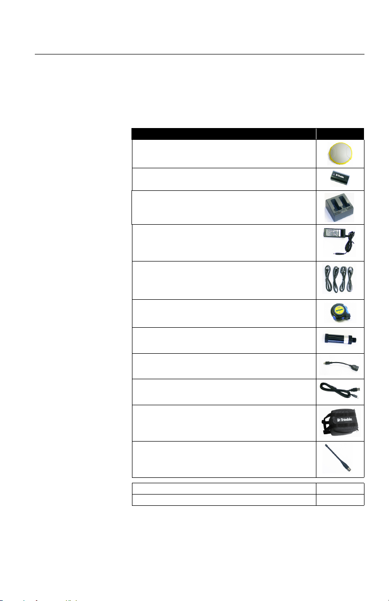
Standard Items The SPS785 L1/L2 GNSS receiver kit includes the following
items.
Item Picture
SPS785 GNSS receiver, with up to 13 pre-installed firmware
options (see page 4)
Li-Ion Battery, 7.4 V, 2800 mAh
Dual Li-Ion Battery Charger
AC/DC Power Block, 65 W, 19 V, 3.43 A, 100-240 VAC, Class
VI
Power Cord Kit (four types) for use with AC/DC Power Block
Tape Measure, 3.6 m (12 feet)
Pole Extension, 7 cm, for use on tripod
USB-to-USB mini OTG Cable
USB data cable
Soft bag, field transport
UHF Whip Antenna, 6 “, rubber duck, 425-475 MHz
UHF Kit (see page 3)-
Office Power Kit (see page 4)-
2
Page 11
UHF Kit
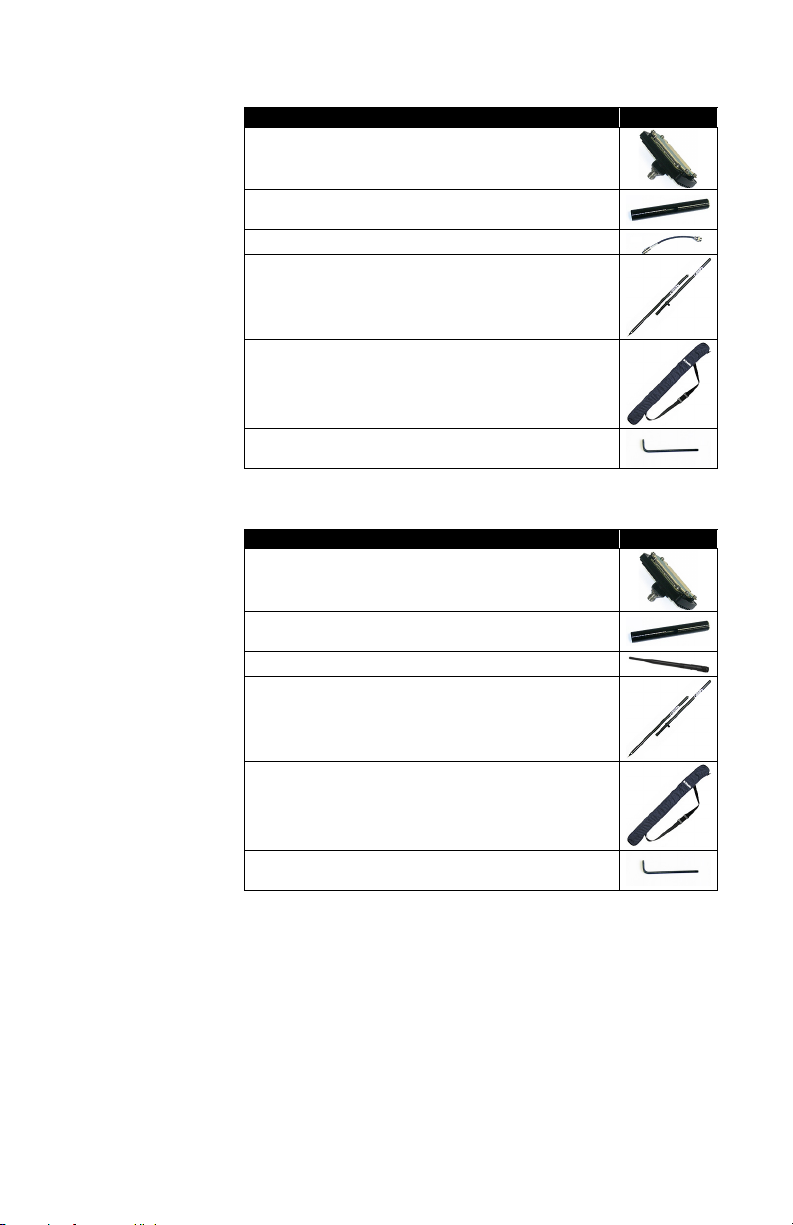
Item Picture
UHF Module (Does not include the UHF antenna)
Pole Extension, 35 cm (1.148 ft) long, with oblong aperture
Coaxial adapter cable (for use with 35 cm Pole Extension)
Rover Range Pole, 1.65 m (5.41 ft) long, carbon fiber, two piece
Soft Bag for Range Pole
T25 Torx Screwdriver, “L” shaped
900 MHz Kit
(Only available within the US and Canada)
Item Picture
900 MHz Module (Does not include the radio antenna)
Pole Extension, 35 cm (1.148 ft) long, with oblong aperture
Radio antenna, 900 MHz reverse polarity, 8”
Rover Range Pole, 1.65 m (5.41 ft) long, carbon fiber, two piece
Soft Bag for Range Pole
T25 Torx Screwdriver, “L” shaped
3
Page 12
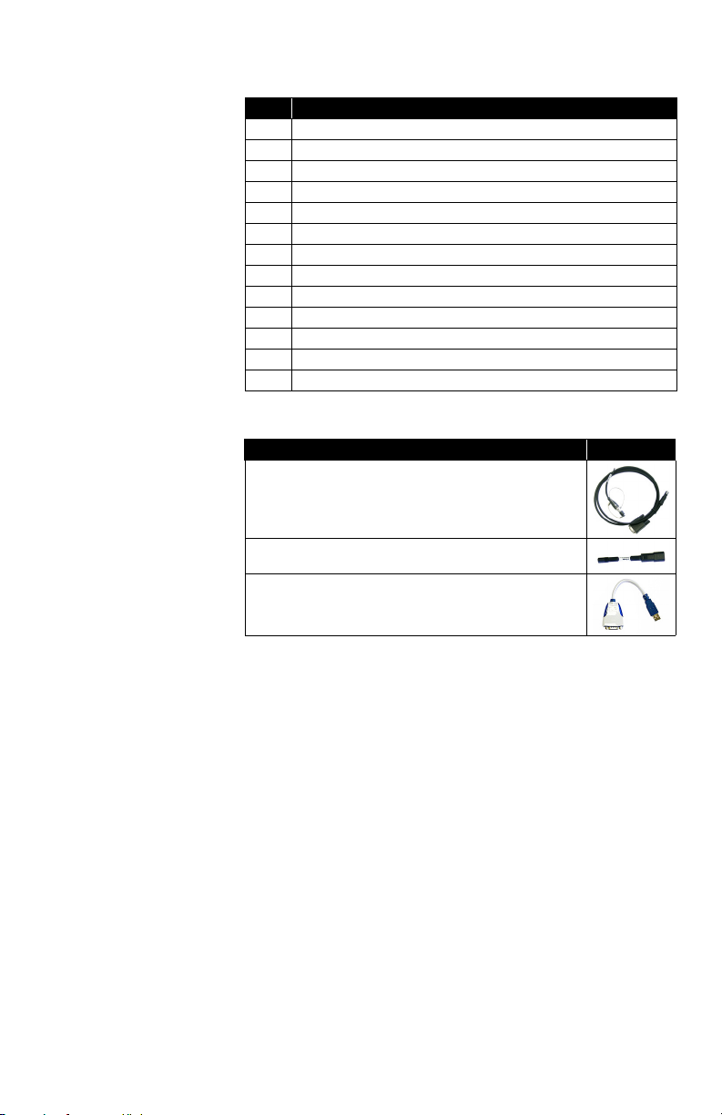
Installed Firmware
Options
Office Power Kit
Label Feature
[@1] NO GEOFENCING
[N] GPS, SBAS, QZSS
[G] GLONASS
[O] GALILEO
[B] BEIDOU
[X] L1 TRACKING
[Y] L2 TRACKING
[S] L3 TRACKING
[L] L-BAND
[6] 10 HZ
[R] RECORD
[J] RTK ROVER
[K] RTK BASE (Upgrade Option)
Item Picture
Power/Data cable, 1.5 m, DB9-f to OS/7P/M to SAE
Adapter cable, 0.15 m, SAE to DC socket (2.1 mm)
RS232-to-USB adapter cable
4
Page 13
Discover Your New Equipment
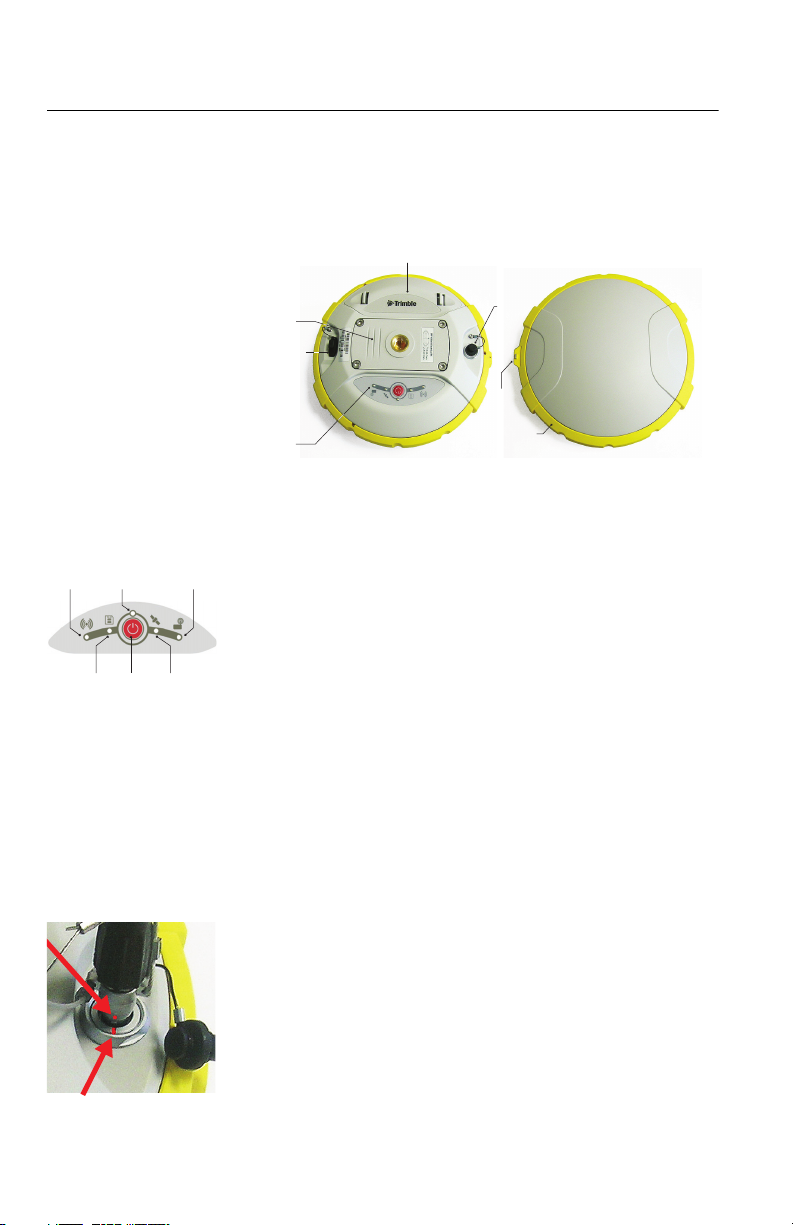
Take a few minutes to discover your new SPS785.
Front Panel
[10]
[2] [4] [7]
[3] [6][5]
[8]
[9]
[11]
[13]
[1]
• [1]: Control panel, consists of the following items, from
left to right (see picture):
– [2]: Bluetooth LED
– [3]: Data recording LED
– [4]: Power LED
– [5]: Power/Configuration button
– [6]: Satellite tracking/Position LED
– [7]: UHF Radio LED
See SPS785 Control Panel Description on page 12 for
more information.
• [8]: 5/8” threaded insert for rod mounting. This part is
securely mounted on a removable plate, thus making up
an assembly that can be replaced with a UHF module
(optional accessory) fitted with its own, specific threaded
hole and central coaxial socket for antenna connection
(see Using the Radio Kits on page 17).
• [9]: Power/data connector (DC input + RS232 serial port
A). The connector socket is protected by a black rubber
cap attached to the receiver case. Always keep the
protection cap on when the connector is not used. This
cap is a non-polarized one.
IMPORTANT: When you connect a cable to that connector,
be sure you align the red markings (a red dot on the plug,
a red line on the socket) before pushing the Lemo plug in.
[12]
5
Page 14
Conversely, when it’s time to disconnect the Lemo plug,
L1 68.7 mm
L2 65.3 mm
please use the attached metal strap to pull the plug out.
• [10]: Battery compartment.
CAUTION - THE TRAPDOOR SHOULD BE REMOVED ONLY
FOR INSERTING OR REPLACING A BATTERY. THE REST
OF THE TIME, PLEASE ALWAYS KEEP FULLY CLOSE
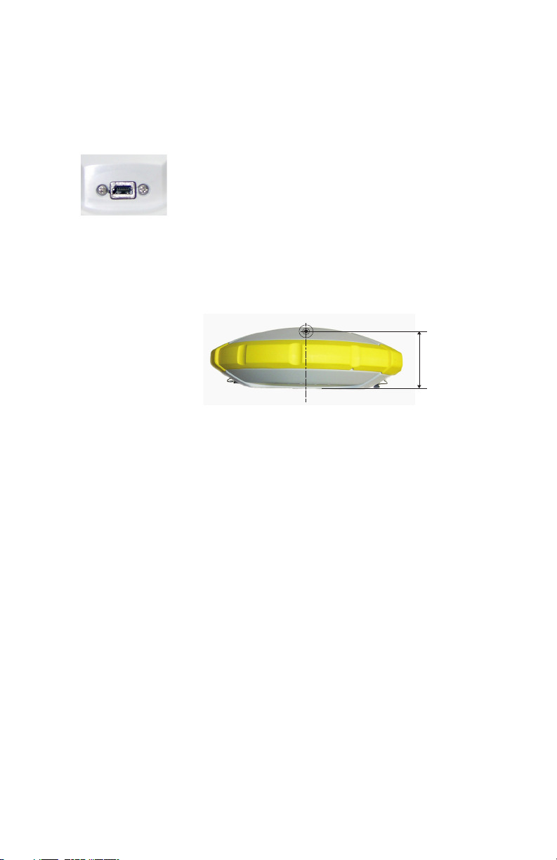
• [11]: Mini-USB connector (standard USB 2.0, up to 12
MHz, OTG (host & device)).
• [12]: Shock absorber making up a robust protection belt
for the receiver against drops to the ground. The height
mark is nested in the shock absorber. See below.
• [13]: Height mark.
.
Phase Center
Location
See diagram below. These are relative measurements.
The field software calculates the real height of the
instrument, based on the location of the L1 phase center.
Whether you provide a vertical or slant measurement of the
antenna base (ARP), the field software you are using will be
able to deduce the real height of the instrument, using the
pre-loaded dimensional parameters (antenna radius, etc.)
specific to the model of GNSS antenna used.
In the case of a slant measurement, the software will also use
the radius of the antenna to determine the instrument height.
6
Page 15
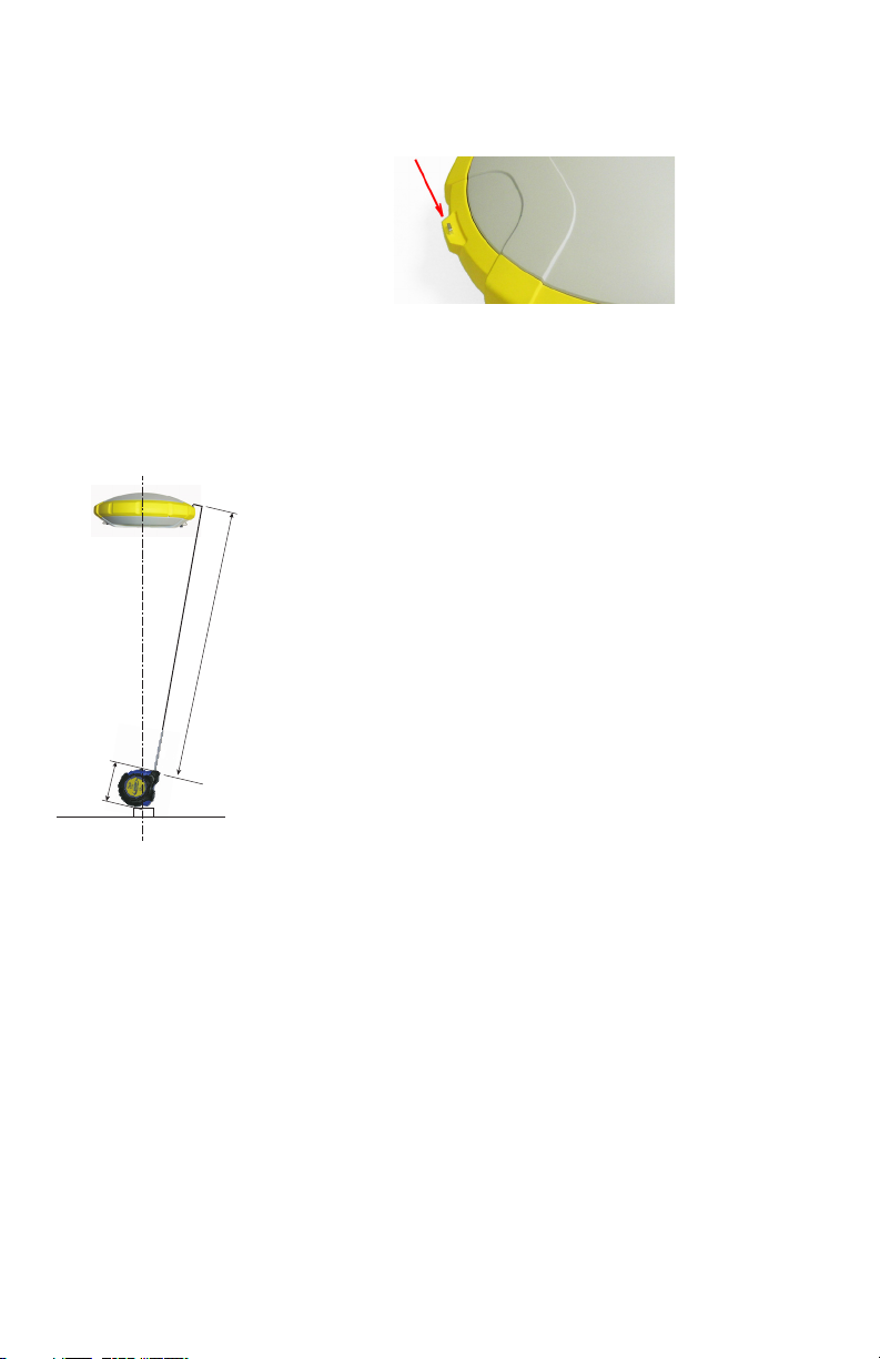
Height Mark The height mark ([8]) is nested in the shock absorber, near
the serial connector.
When the receiver is mounted on a tripod – for use as a base
for example – making a slant measurement to determine the
instrument height is often more convenient than making a
vertical measurement from the ground mark to the antenna
base.
In this case, the height mark can be used to hook the measure
tape (standard accessory) so you can unroll the tape down to
the ground mark and conveniently measure the distance
between these two points. However because the housing of
the measure tape is inserted in the path between the two
points, you should make the following correction to obtain the
real value of slant measurement:
Slant Measurement = Measured Distance + Delta L
Where “Delta L” is the length of the tape measure housing.
Measured distance
Delta L
Delta L= 0.073 m or 0.2396 ft (2 7/8 inches), as mentioned on the housing.
When the field software requests your input to determine the
instrument height, you will then choose to enter the slant
measurement, rather than the vertical one. The software will
then be able to deduce the real height of the instrument from
the known dimensional parameters of the antenna and the
slant measurement you will have entered.
7
Page 16

Buzzer The buzzer can be heard in the following cases:
• Bluetooth:
– When the data collector establishes a Bluetooth
connection with the receiver,
– When this connection gets lost.
• Internal battery: When the internal battery gets low (less
than 20% of nominal charge), the buzzer sounds briefly.
When less than 10% is left, the buzzer sounds
continuously for a few seconds until the receiver safely
shuts down.
• Power button: After a long press (2-3 seconds) on this
button:
– To start or stop data logging (see also below).
– To enter the radio mode
– To power off the receiver.
In all three cases, hearing the buzzer means your request
has been acknowledged and you can release the button.
• When entering the radio mode.
• Enabling/Disabling Data Logging from the Power button:
The buzzer will sound at the end of the 2 or 3 seconds of
holding down the Power button to either start or stop data
logging (see also Raw Data Logging in Standalone Mode
on page 22).
• Downloading Files: After connecting a USB key to the
receiver, the buzzer will first sound when the USB key is
ready for use, and then after you have pressed briefly the
Power button to start downloading files to the USB key.
Another beep will finally be heard when the file transfer is
complete (see Downloading Raw Data Files to a USB Key
on page 22).
8
Page 17
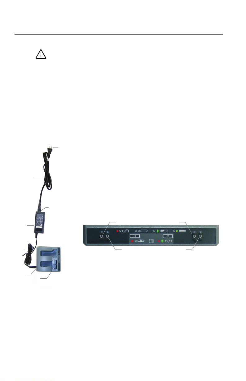
Using SPS785 for the First Time
[1]
[2]
[3]
[4]
[5]
[6]
[7]
[9]
[8][8]
[9]
WARNING - This receiver uses a rechargeable Lithium-ion
battery. To avoid personal injury or equipment damage, make
sure that you read and understand the safety information at
the front of this guide.
The battery is shipped partially charged. Depending on the
time elapsed since then, the remaining charge may be even
less. For this reason, you should first recharge the battery
completely before first use. (See warnings and safety
information at the front of this guide.)
Charging the
Battery
1. Set up the battery charger as follows:
– Connect the output cable ([1]) of the AC/DC power
block ([2]) to the battery charger input ([3]).
– Choose the power cord ([4]) that is suitable for your
country.
– Connect the end of the power cord to the AC/DC block
input ([5]), and the other to a power outlet ([6]). This
powers up the battery charger, causing the two LEDs
[8] to turn solid red.
2. Insert the battery ([7]) into one of the two slots on the
battery charger (give the right orientation to the battery).
When the battery is detected, the corresponding red LED
([8]) will go off and the nearby LED ([9]) will start blinking
green to indicate that the battery is being charged.
3. Charging the battery will take a few hours. When the
battery reaches full charge, the LED ([9]) will turn solid
green (see also printed instructions provided with the
charger).
4. Remove the battery from the charger when fully charged.
NOTE 1: The battery may be left on the charger for an
indefinite period of time without causing any damage to
the charger or the battery.
NOTE 2: If you also have a spare battery, the two batteries
can be inserted onto the charger. The batteries will be
charged simultaneously.
9
Page 18
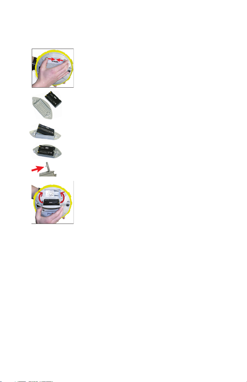
Inserting the
[10]
[11]
[14]
[15]
[12]
[13]
Battery
The battery trapdoor of the SPS785 can entirely be detached
from the receiver case.
As explained below, the battery is first inserted into the inner
side of the trapdoor and then inserted into the receiver case,
together with the trapdoor.
• Open the battery trapdoor: Using your thumb and middle
finger, press on the two locks to free and remove the
trapdoor ([10]).
• Place the trapdoor upside down on a horizontal plane,
curved edge to the right. Place the battery nearby, electric
contacts upward, and as shown ([11])
• Take the battery and insert one of its end into the trapdoor
([12]), then gently push the other end until the battery is
fully inserted ([13]).
The trapdoor is fitted with an auto-locking system ([14])
at both ends of the battery that will keep the battery firmly
in position once fully inserted.
• Hold the receiver case upside down in one hand, take the
battery and trapdoor in the other hand and insert them
into the battery compartment ([15]). A click can be heard
when the trapdoor gets locked into the receiver case.
Note: To remove the battery from the trapdoor, gently push aside one
of the locking legs to free that end of the battery. Then it’s easy taking
the battery out of the trapdoor.
10
Page 19
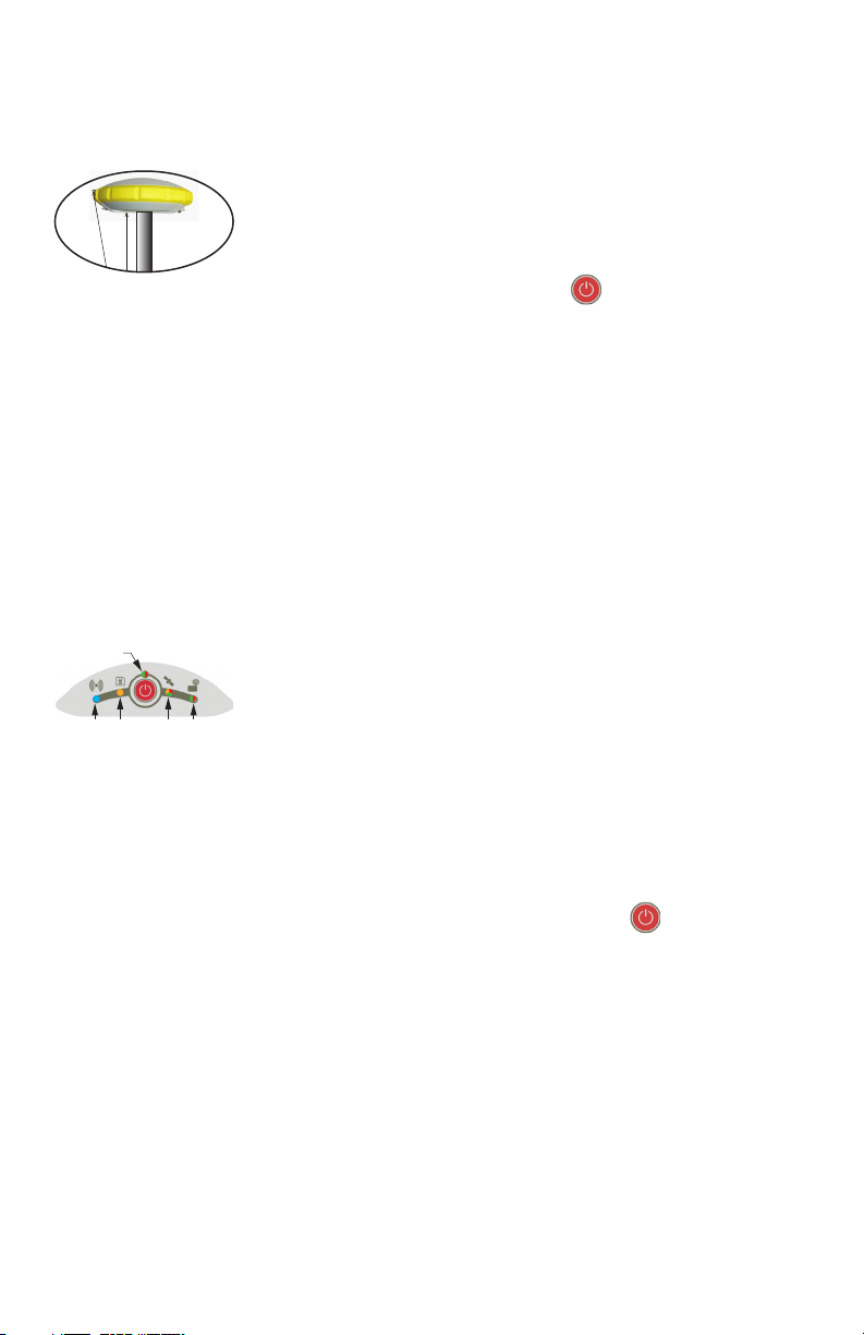
Setting up the
[17]
[18]
(Raw Data
Logging)
[19] [20]
SPS785
1. Mount the receiver and data collector on a range pole
(rover), or a tripod (base).
2. Measure and write down the vertical (Hv) or slant (Hs)
[16]
Hs
Hv
distance from the ground mark to respectively the lower
part of the receiver (ARP) (rover) or to the height mark
(base) (see [16]). This measurement will be required by
your field software in a further step.
3. Turn on the SPS785 by holding depressed for about
3 seconds. The Power LED ([17]) turns solid orange for
about 15 seconds (receiver booting...), then solid green
(with internal battery) or solid red (if an external power
supply is used). The receiver is ready to use.
4. Meanwhile, turn on the data collector and run your field
software.
Running a Survey 1. Follow the instructions provided by your field software to
use the SPS785 as desired (rover or base). The receiver
will beep, and the Bluetooth LED ([18]) will stay solid
blue, when a Bluetooth connection is established with the
data collector.
In a rover, the Satellites/Position LED ([19]) will stay solid
green when a fixed position solution is computed. With a
rover using the internal radio (option), the Radio LED
([20]) will turn green when corrections are being received.
2. Start your survey job when ready.
3. From time to time, take a look at the Power LED ([17]) on
the control panel.
When the Power LED starts blinking green – first at a slow
rate (1 sec), then at a faster rate (5 flashes a second) –
that will mean the battery is too low and the receiver will
soon shut down.
Ending a Survey 1. After your field survey is complete, hold depressed for
about 3 seconds. Release it when the Buzzer emits a
sound. The Satellites/Position LED ([19]) starts blinking
at a fast rate. The receiver will shut down after about
10 seconds.
2. Don’t forget to charge the battery at the end of your day.
The battery will charge overnight.
NOTE: Need to download raw data files from the receiver?
Refer to Collecting Raw Data Files on page 22.
11
Page 20
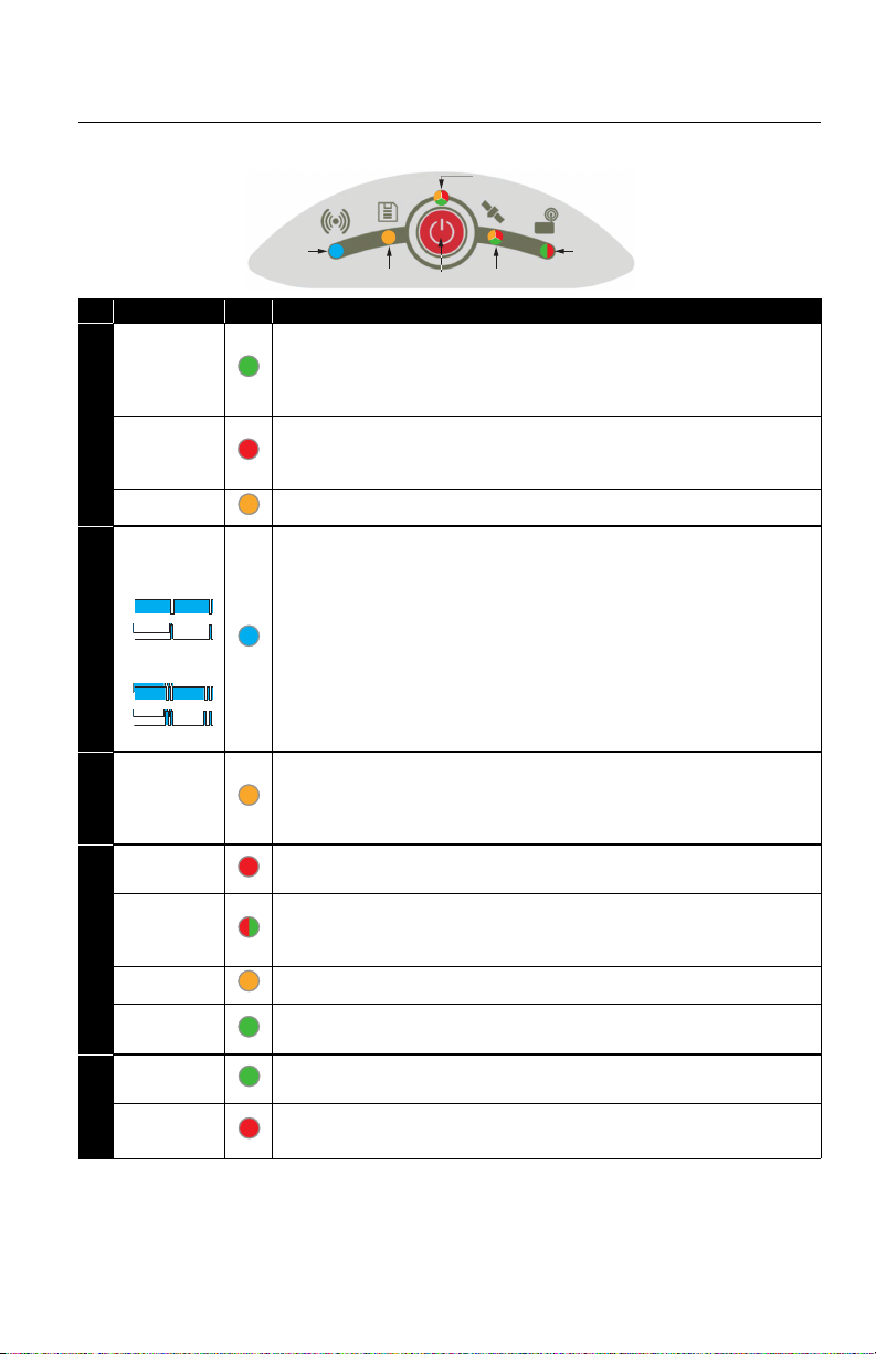
SPS785 Control Panel Description
ON
OFF
ON
OFF
[1]
[2]
[3]
[4]
[6]
[5]
No. Blinking Rate* Color Meaning
•On
•Slow
•Fast
• Internal battery is used. Remaining charge > 20%.
• Internal battery is used. 10% < remaining charge < 20%. Short beep heard at 20%
• Internal battery is used. Remaining charge < 10%. Buzzer emits continuous
sound. Only a few seconds left before SPS785 safely shuts down.
Power LED [1]
•On
•Fast
• External power source is used. Input voltage is within expected range.
• External power source is used. Input voltage is out of range. Please change the
power source immediately.
• On • Power-on sequence in progress.
•Slow
•On
Base***:
•
•
Rover***:
•
Bluetooth LED [2]
•
ON
OFF
ON
OFF
• Bluetooth is on but no connection is active yet.
• Bluetooth connection to communicate with a data collector is active.
Base:
• Two Bluetooth connections are active: Long-range Bluetooth and data collector.
• One Bluetooth connection is active: Long-range Bluetooth (sending corrections to
rover).
Rover:
• Two Bluetooth connections are active: Long-range Bluetooth and data collector.
• One Bluetooth connection is active: Long-range Bluetooth (receiving corrections
from base).
•Off
•On
•Slow
•Fast
Log LED [3]
•Slow
•Fast
• No data logging is in progress.
• Data is being logged to internal memory.
• Space available in internal memory is getting low.
• No more space is available in memory. End of data logging is imminent.
• No satellites are tracked.
• During a power-off sequence, starting when the buzzer emits a sound.
• Mixed • Satellites are tracked but no position is available yet. Green flashes indicate the
number of satellites tracked. 5 green flashes means 5 or more satellites tracked.
Red flash is just a delimiter.
• On • Autonomous, DGPS or SDGPS position solution is available
Sat/Pos LED [4]
•Slow
•On
•Off
• Variable
•Off
• Variable
Radio LED [5]
• Floating position solution is available.
• Fixed position solution is available.
• No corrections data are received.
• Corrections data are being received.**
• No corrections data are sent out.
• Corrections data are being sent out.**
*: All the terms used to describe blinking rates are clarified in the table on the next page.
** LED stays lit from beginning to end of data reception / transmission.
*** Does not necessarily mean corrections are being received or sent.
12
Page 21
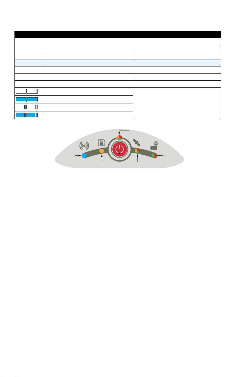
Blinking Rate Description General Meaning
ON
OFF
ON
OFF
[1]
[2]
[3]
[4]
[5]
[6]
Off LED is off Receiver or function turned off
On LED permanently lit (solid color) Normal operation
Slow 0.5 s (equal On/Off times) Normal operation
Very slow 1.5 s (equal On/Off times) Radio configuration mode (see flowchart below)
Fast 0.1 s (equal On/Off times) Alert
Variable LED stays lit for a certain time Refer to radio LED; See previous page.
Mixed Mixed colors: red and green alternate See satellite/position LED on previous page.
Off but with one brief blue flash every 3 sec.
ON
OFF
ON
OFF
Solid blue with one brief “off” time every 3 sec.
Off but with two brief blue flashes every 3 sec.
Solid blue with two brief “off” times every 3 sec.
Specific to Bluetooth LED; See previous page.
Power button [6] is primarily used to control receiver power:
• Turning On the Receiver: Hold the button depressed until the Power LED turns solid
orange (this takes about 2 to 3 seconds). Then release the button. This starts a
power-on sequence. A few seconds later, the Power LED will turn solid green (with
internal battery) or solid red (with external power supply), meaning the receiver is
on and ready for use.
• Turning Off the Receiver: Hold the button depressed for about 2 to 3 seconds, until
the buzzer emits a sound, then release the button. This starts a power-off sequence,
with the Satellites/Position LED blinking red at a fast rate. The LED will go off a few
seconds later, meaning the receiver is off.
Power button [6] is also used to reset the receiver (see Restoring Factory Settings on
page 29) and to download raw data files to a USB key (see Downloading Raw Data Files
to a USB Key on page 22).
Power button [6] is also used to access the two functions below. This is achieved by
combining short and long presses on the button.
• Raw Data Logging: Enabling/disabling raw data logging.
• Radio Configuration: If an internal radio is used, making its port accessible through
receiver port A for radio configuration (later you will need to turn off the SPS785 to
exit this mode).
For more details on these two settings, see flowchart below.
13
Page 22
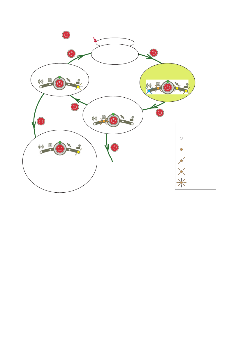
Power Up
Normal
Operating Mode
Set Data
Logging
Set Radio
Press & release
Press briey
Press & release
Press for 2 sec.
Press for 2 sec.
(buzzer then beeps)
Press for 2 sec.
(buzzer then beeps)
Data logging is now on if it
was o, or o if it was on.
Receiver automatically returns
to normal operating mode.
Radio Mode
Radio port now
connected to receiver port A.
Turn o receiver to escape
from this mode.
Conventions used
for LED states:
O
On (solid color)
Very slow blinking
Slow blinking
Fast blinking
Conguration
Mode
Press & release
On the flowchart, each step is identified by a particular combination of LED states.
Whatever the step, normal operating mode is restored after 10 seconds of user
inactivity.
NOTE: Other actions are possible from the control panel. See Downloading Raw Data
Files to a USB Key on page 22 and Restoring Factory Settings on page 29.
14
Page 23
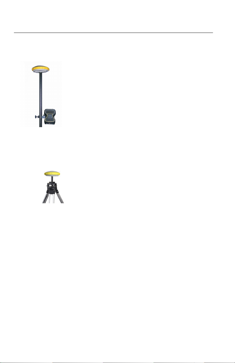
Introducing SPS785 as Rover
Network Rover
The SPS785 has no network connectivity device of its own,
but the data collector, to which it is connected over Bluetooth
to run the field software, may have this capability.
So network corrections received using the data collector
modem will be forwarded to the SPS785 over Bluetooth as
well.
In this case of use, the SPS785 will be able to deliver RTK
positions using one of the following standard network
connection types:
•VRS
•IBSS
Rover Using
Local Base
The expression “local base” refers to a base you own and can
fully control (operating sessions, location, etc.).
The rover can receive RTK corrections from the local base via:
• Long-range Bluetooth
• Radio (internal at the rover, internal or external at the
base). See Using the Radio Kits on page 17.
15
Page 24
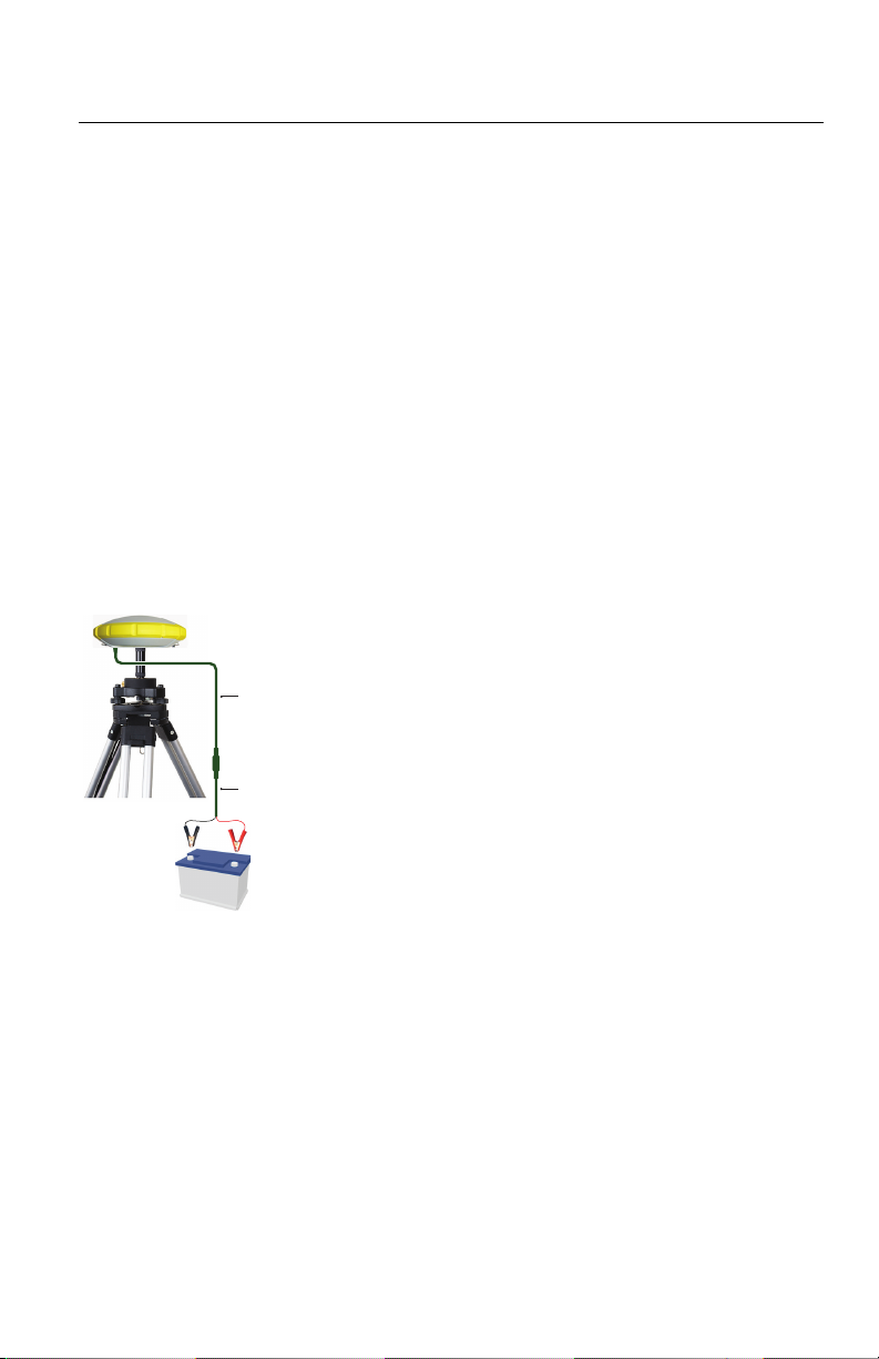
Introducing SPS785 as Local Base
_
+
[1]
[2]
Possible Local Base
Configurations
Internal vs.
External Power
Source
The SPS785 can be used as a local base, delivering its
corrections through one of the following devices:
• Long-Range Bluetooth: For baselines less than 800
meters (0.5 mile), the local base will be able to deliver its
corrections to a rover over a long-range Bluetooth
connection.
• UHF radio (optional accessory): The local base may be
fitted with an internal radio module (internal UHF radio,
2 W TRx), or an external radio delivering more RF power.
For more information on the internal radio module, see
Using the Radio Kits on page 17.
Consider the following before setting up a local base:
• If the base is left unattended for the whole day, you may
want to power it from an external power source that will
provide enough power for your work day.
In this case, you may use specific cables (not provided) to
connect the receiver to an external 12-Volt battery. See
diagram in which [1] is cable P/N 95715 and [2] is cable
P/N 83223-02 (Cable Kit P/N 104024-00).
NOTE: If you need to change the fuse on cable P/N
83223-02, please use the same type of fuse as the one
originally provided (15 A @32 V). This is mandatory.
• If you intend to work close enough to the base, or someone
is in charge of keeping the base running throughout the
day, you may decide to power the base from its internal
battery.
For a day’s work, you may need two batteries: A fresh one
inserted in the base at the beginning of the day, and the
second one may be needed sometime before the end of
the day.
16
Page 25

Using the Radio Kits
The radio kits are used to implement a radio-based,
standalone RTK base/rover system (see page 3 for more
details on all the items provided in these kits).
UHF Kit With this configuration the user has the ability to receive base
observations via the UHF module. Additionally, with the RTK
Base upgrade option, the user can setup and transmit their
own base. For a complete RTK base/rover system you will
need two UHF kits.One kit will be installed on the base side,
the other on rover side. Additional information on using the
SPS785 as a base can be found on page 16.
Configuring your radio modules is required before you can use
them. This procedure is discussed in Configuring the Radio
Module on page 19.
900 MHz Kit (Only available within the US and Canada)
With this configuration the user has the ability to receive
license free base observations via the 900 MHz radio module.
Transmission via 900 MHz is not supported.
Configuration of the radio module is performed within the
field software.
17
Page 26
Installing the
[3]
[1]
[2]
[4]
[5]
Radio Module into
the Receiver
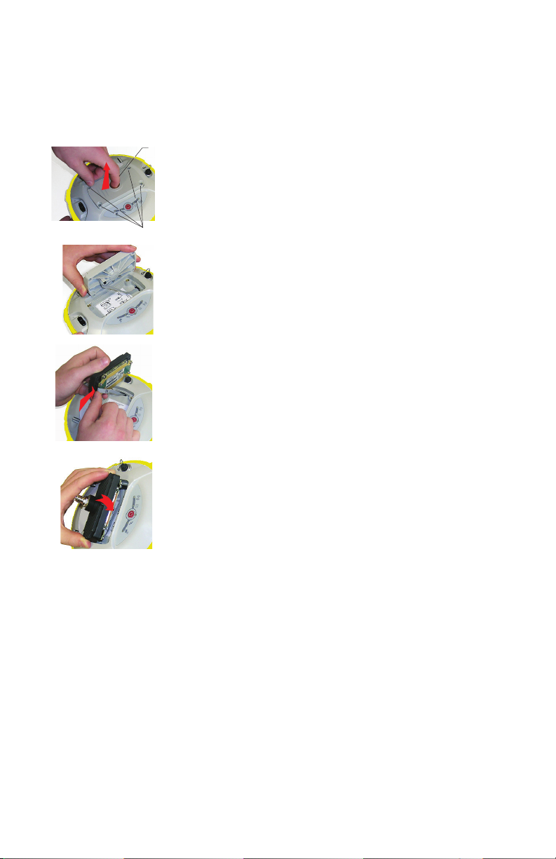
• Power off the SPS785 and turn it upside down.
• Use the L-shaped Torx screwdriver provided in the
SPS785 UHF kit to loosen and remove the four screws
([1]) securing the 5/8” threaded insert plate.
• Insert a finger into the 5/8” threaded hole ([2]), then
gently pull the plate out of the receiver, making sure you
free the ribbon cable anchored to the plate without
damaging it ([3]).
• Put away the 5/8” threaded insert plate in a safe place,
possibly for subsequent use.
• Take a look at the instructions printed on the label located
in the bottom of the recess.
• Connect the end of the ribbon cable (a 12-contact flat
connector) to the UHF module ([4]) as instructed on the
label (point 1).
• Insert the UHF module into the recess ([5]) as instructed
on the label (point 2).
• Re-use the four screws and Torx screwdriver to secure the
UHF module onto the receiver. Tighten the screws to
preserve receiver watertightness (torque meter: 3 N.m).
IMPORTANT: After installing (or removing) the internal
radio, you must reset the receiver (through hard reset, see
page 29, or via field software).
18
NOTE 1: The insertion of the radio module DOES NOT modify
the ARP (Antenna Reference Point) of the GNSS antenna.
NOTE 2: When switching between the UHF and 900 MHz
radio module on the same receiver, you will need to perform
a factory reset. See Restoring Factory Settings on page 29.
Page 27
Configuring the
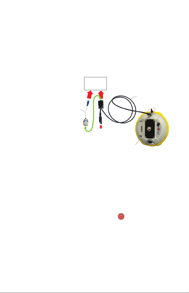
Power/Data Cable *
SPS785
To O c e
Computer
(If required, may be
connected to AC/DC
power block via
SAE/Jack Adapter Cable *)
RS232-to-USB
Adapter Cable *
RS232
Serial Port A
and DC Input
Via USB or DB9
Radio Module
The standard settings of the radio module can easily be
changed from the field software.
For more advanced radio settings, use one of the procedures
below:
• Preferred method - Set UHF frequencies via Virtual
Warehouse and install on the SPS785 using Tri mb l e
Installation Manager. See page 24.
• Other method: Use cable P/N59044-10 from the Office
Power Kit to connect the receiver to the computer (see
diagram below).
*: All these items are part of the Office Power Kit P/N 94336-00 (option).
Use the RS232-to-USB adapter cable if your computer is fitted with USB
connectors (and no DB9 connector).
NOTE: Cable P/N59044-10 is a Y-shaped cable also
allowing you to power the receiver from an AC outlet (via
the AC/DC power block) rather than from the receiver
battery (see also Connecting SPS785 to your Computer on
page 25). When applied to the receiver’s DC input, the
external power source has priority over the internal battery,
which means the battery can be left safely inside the
receiver (it won’t be drained).
• Make three brief presses on ,. The radio LED should
now be flashing quickly. Now press and hold the power
button for about 2 seconds until the buzzer beeps. As a
result, the receiver switches to radio mode, providing
direct access to the UHF module via the receiver’s port A.
•Run Trimble TDLCONF software on the computer and
configure the radio to meet your requirements. Refer to
TDLCONF instructions to complete this step.
• Power down the unit to exit radio mode.
19
Page 28

Completing Rover
[6]
[7]
Radio Setup
Once the radio module has been secured to the receiver (see
Installing the Radio Module into the Receiver on page 18)
and properly configured, do the following:
• Screw the radio whip antenna onto the coaxial connector
of the radio module ([6]). The antenna will therefore be
oriented vertically upside down when used.
NOTE: Being placed in vertical position, the radio antenna
will stay as sensitive as if it were oriented the other way
round.
• Take the top rod of the fiberglass range pole provided in
the radio kit. Insert first its end with special tapping, not
5/8” tapping, around the radio antenna ([7]).
CAUTION - This special tapping uses a thinner thread
compared to the standard 5/8” one. For this reason, be
careful when you start screwing the rod into the radio
module. Make sure the rod fits well in the threaded part
of the radio module.
• Screw the top rod onto the threaded part of the radio
module. Spin the rod, rather than the receiver, when doing
this.
• The receiver + top rod assembly can then be mounted on
top of the other part of the range pole (the bottom rod).
• Complete the setup of your SPS785 + radio rover system
by attaching the data collector onto the range pole. You
are now ready for a survey.
Completing Base
Radio Setup With
External UHF
Antenna
20
Two types of base setups are possible with an external UHF
antenna:
• The UHF antenna may be installed in vertical position on
the same tripod as the base receiver.
For this setup, you may use an external radio kit (sold
separately).
• The UHF antenna may be installed on a separate tripod at
some distance from the base receiver, but still remaining
compatible with the length of the coaxial cable you will be
using. The UHF antenna should be installed at the highest
possible height.
Page 29
On receiver side, after the UHF module has been secured to
[12]
[13]
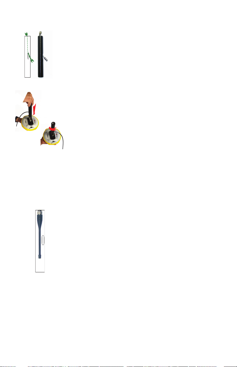
the receiver and properly configured, do the following
whatever your choice of antenna setup:
• Pass the male connector of the coaxial adapter cable
(PN 96845) through the oblong hole of the pole extension
(PN 114090) and make it go out of it at its upper end (see
[12]).
• Connect it to the coaxial output of the UHF module.
• Screw the pole extension to the threaded part on the UHF
module (see [13]). Spin the pole extension, rather than
the receiver, taking care not to jam the coaxial cable
extension when doing this.
• Secure the receiver/pole extension assembly onto the
tripod.
• Connect the other end (female connector) of the coaxial
cable extension to the coaxial cable coming down from the
UHF antenna.
• Set up the base on the chosen reference point.
Completing Base
Radio Setup With
Internal UHF
Antenna
The UHF antenna is connected directly to the UHF module
and is hidden in the pole. The pole is installed on top of a
tripod. Follow the same instructions as with a rover (see
Completing Rover Radio Setup on page 20) to install the
internal UHF antenna, but this time you will be using:
• A quarter-wave antenna.
• The pole extension with the oblong hole (from the UHF
kit). You don’t need to use the coaxial adapter cable.
21
Page 30
Collecting Raw Data Files
Raw Data Logging
in Standalone
Mode
Downloading
Raw Data Files
to a USB Key
You can control raw data logging sessions directly from the
SPS785, without the need for a data collector. After turning
on the receiver, do the following to enable raw data logging:
• Make a brief press on . The receiver enters the
configuration mode (LEDs are all in slow blinking state).
• Make another brief press on . The data logging LED
starts blinking amber at a fast rate.
• Hold depressed for about 2-3 seconds until the
buzzer emits a sound. Data logging is then started and you
will see the data logging LED now solid amber. The
receiver has automatically escaped from the configuration
mode and is now operating in normal mode.
To stop data logging, repeat exactly the previous three steps.
See also flowchart on page 14. This will turn off the data
logging LED.
The first time you connect the USB port to a computer, the
required driver is installed automatically on the computer.
After the driver has been installed, follow the instructions
below.
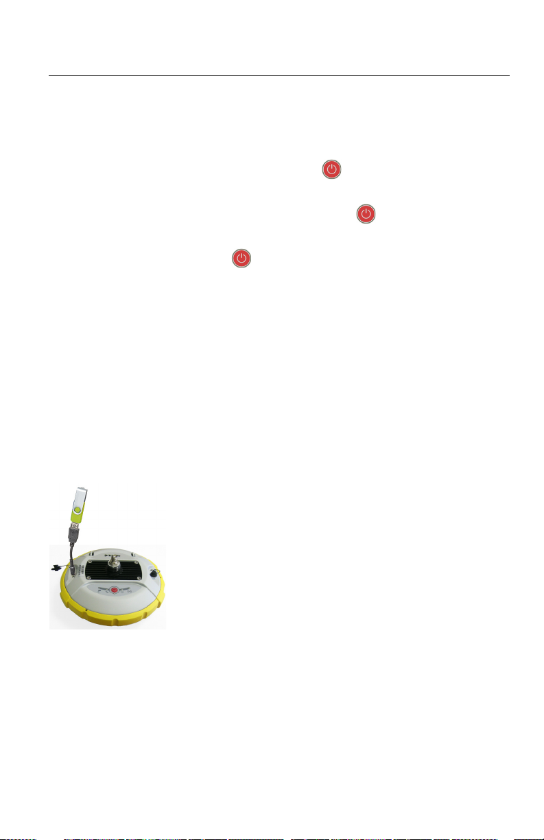
• Connect the USB key to a mini-USB-to-USB adapter (see
picture) (PN EGL-Z2001).
• Connect the other end of the adapter to the SPS785. After
about 2 seconds, the buzzer sounds briefly, meaning the
USB key is ready for use, and the Log LED starts flashing
amber at a fast rate. If you do nothing in the next 4
seconds, the Log LED will turn off and you won’t be able
to start the download sequence.
• So while the Log LED is still flashing, press the Power
button. This causes the buzzer to sound briefly meaning
the receiver is now downloading all its G-files to the USB
key. The buzzer will emit another brief sound when the file
transfer is complete.
• Disconnect the mini-USB-to-USB adapter from the
SPS785.
NOTE: This procedure will not delete the downloaded files
from the receiver.
22
Page 31

Downloading Raw
Data Files Directly
to a Computer
Use Trimble File Manager. See page 24.
Post-Processing
Raw Data Files
This can be done using Trimble Business Center (TBC)
software.
23
Page 32

Appendix
Trimble Installation
Manager
Trimble File
Manager Software
Utility
The Trimble Installation Manager (TIM) allows the user to
download receiver firmware, load UHF frequencies, install
optional receiver upgrades and view receiver information.
TIM can be downloaded from:
https://www.trimble.com/installationmanager/
Once installed, connect your powered-on SPS785 to your PC
using the provided USB data cable.
NOTE: UHF frequencies are programmed by your dealer.
Please contact your dealer for additional information.
Trimble File Manager allows you to copy “log” files and Gfiles directly from the receiver’s internal memory to the
desired folder on your office computer.
Additionally you can delete any G-file or “log” file from the
receiver’s internal memory.
G-files are GNSS raw data files in proprietary format (ATOM).
“Log” files are editable text files listing all the operations
performed by the receiver in one day.
Trimble File Manager is available from the Trimble website as
an exe file (TrimbleFileManagerSetup.exe) through the link
below:
https://construction.trimble.com/SPS785
24
Installing Trimble File Manager
Trimble File Manager is very easy to install:
• Download the exe file from the Trimble website (use above
link).
• Double-click on the exe file to complete the installation.
Page 33
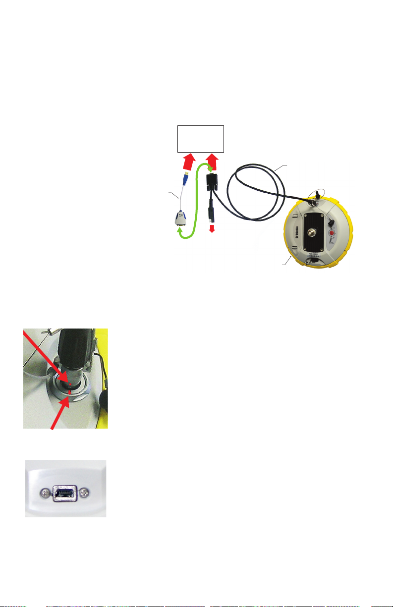
Power/Data Cable *
SPS785
To O c e
Computer
(If required, may be
connected to AC/DC
power block via
SAE/Jack Adapter Cable *)
RS232-to-USB
Adapter Cable *
RS232
Serial Port A
and DC Input
Via USB or DB9
Connecting SPS785 to your Computer
There are different ways of communicating with the receiver:
• Through Bluetooth.
• Through an RS232 line, using port A on the receiver, and
a DB9 or USB socket, on computer side (see illustration
below). The default speed for port A on receiver side is
115200 Bd.
*: All these items are part of the Office Power Kit P/N 94336-00.
The Office Power Kit required for this serial connection is
designed to let you power the receiver from an AC outlet
rather than from the receiver battery (see illustration
above).
When applied to the receiver’s DC input, the external
power source has priority over the internal battery, which
means the battery can be left safely inside the receiver (it
won’t be drained).
IMPORTANT: Be sure you align the red markings (a red dot
on the connector, a red line on the socket) before pushing
the Lemo connector in. Conversely, when it’s time to
disconnect the Lemo connector, please use the attached
metal strap to pull the connector out.
• Through USB (Preferred). Connect the SPS785 to the
computer via the USB-to Mini Universal cable provided.
The first time you make this connection, the required USB
driver will be installed automatically on the computer to
make that connection possible.
When using the receiver’s USB port, you can still use the
previous setup to power the receiver through its DC input
(in this case, you don’t need to connect the DB9
connector of the Power/Data cable to the computer).
25
Page 34
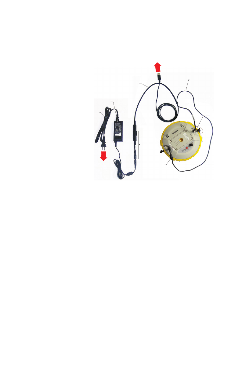
In this setup, you can alternately replace the Power/Data
Power
Cord
AC/DC
Power Block
Power Cable **
USB-to-Mini
Universal
Cable
SPS785
SAE/Jack-f
Adapter
Cable *
To A C
Outlet
To O c e
Computer
DC Input
cable (P/N 59044-10) from the Office Power Kit with
cable P/N 95715 from the Field Power Kit (option, P/N
104024-00). See diagram below.
*: This item is part of the Office Power Kit P/N 94336-00.
**: This item is part of the Field Power Kit P/N 104024-00 (option)
26
IMPORTANT: After removing the USB cable, and before
going back to the field with your receiver, please place the
protection lid back on the USB connector.
Page 35
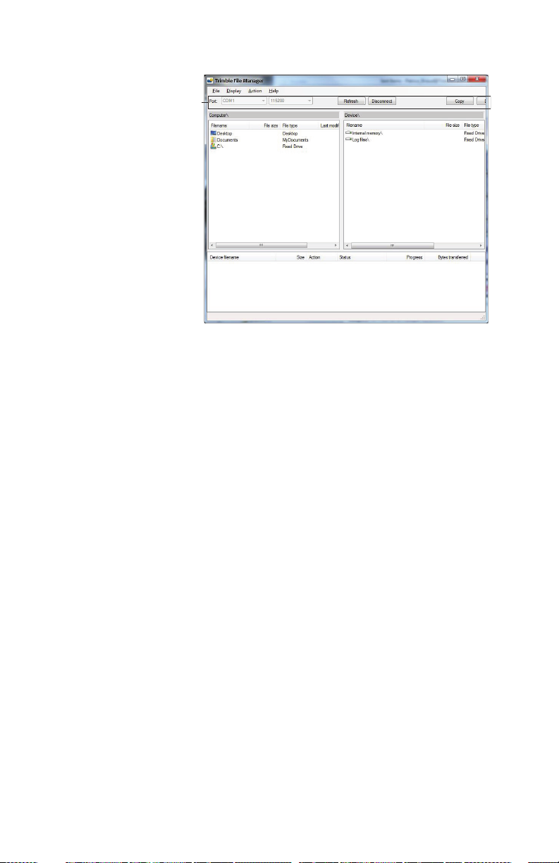
[2]
[1]
[3]
[4]
Getting Started
With Trimble File
Manager
[1]: Trimble File Manager toolbar. This toolbar consists of the
following items:
• Port and baud rate scroll-down lists: Let you choose which
serial port is used on computer side for the connection
with the receiver (baud rate only makes sense when an
RS232 serial line is used). Use 115200 Baud to
communicate with SPS785.
• Connect / Refresh button: Connect allows you to activate the
connection between the computer and the receiver via the
chosen serial line.
When the connection is established, the button is
changed into Refresh, which allows you to update the
content of the two Trimble File Manager panes ([2] and [3]
described below).
• Disconnect button: Allows you to deactivate the connection
currently established between the computer and the
receiver.
• Copy button: Copies the file(s) selected in pane [3] to
pane [2]. In pane [2], you have to open the folder where
to copy to before clicking on the Copy button.
NOTE: Copied files have different creation dates and
times compared to those of their respective original files.
The new dates and times are those corresponding to when
the files were copied.
• Delete button: Deletes the files currently selected in pane
[2] or [3].
27
Page 36

[2]: Pane showing the content of the currently open folder on
computer side.
[3]: Pane showing the content of the currently open folder on
receiver side. The receiver’s root folder contains two or three
sub-folders:
• Internal memory: Lists all G-files recorded by the receiver
in its internal memory
• Log files: Contains log files (one per day). Each log file
lists all the actions performed by the receiver in one day.
• USB key, if one is currently connected to the receiver.
To open a folder, double-click on it. To go back to the parent
folder, click on .
[4]: Pane showing copy/delete operations in progress, and all
those completed since the connection with the receiver was
established. This pane is cleared at the beginning of each
new working session of Trimble File Manager.
Establishing a Connection with the Receiver
• Set up the physical connection (RS232 or USB as
explained in Connecting SPS785 to your Computer on
page 25)
• Turn on the receiver.
• Launch Trimble File Manager on your computer. This
opens the Trimble File Manager window.
• For an RS232 connection, first edit the line settings
(default baud rate for receiver is 115200 Bd) then click
on the Connect button. For a USB connection, select the
right COM port and then click on the Connect button.
As a result, the pane on the right-hand side of the window
lists the two or three folders that can be seen on the
receiver.
28
Copying Files to the Office Computer
• In the right-hand side of the window, double-click on the
sub-folder containing the files you want to copy to the
computer.
(If needed, click on to go back to the parent folder and
open another sub-folder.)
• In the left-hand side of the window, browse your computer
to the folder where to copy the files (recipient folder).
• In the right-hand side of the window, highlight the file(s)
you want to copy.
Page 37

• Click on the Copy button. Files are then copied, as
requested. The lower part of the screen provides reports
information on the copy operations in progress.
Deleting Files from the Receiver
• In the right-hand side of the window, double-click on the
sub-folder containing the files you want to delete from the
receiver.
(If needed, click on to go back to the parent folder and
open another sub-folder.)
• Still in the right-hand side of the window, highlight the
file(s) you want to delete.
• Click on the Delete button. Files are then deleted. The
lower part of the screen provides reports information on
the delete operations in progress.
Restoring Factory
Settings
This can be done starting from a powered-off receiver. Just
hold down the Power button for about 10 seconds. This
causes a reset procedure to be started. At the end of this
procedure, all factory settings are restored, except the
following, which are kept unchanged:
• Bluetooth
– PIN code
– Receiver’s Bluetooth name.
29
Page 38

Technical
Specifications
GNSS Characteristics
• 240 GNSS channels
– GPS L1 C/A, L1P (Y), L2P (Y), L2C
– GLONASS L1 C/A, L2 C/A, L1P, L2P
– QZSS L1 C/A, L2C, L1Z, L1C
– BeiDou B1, B2, B1C
– Galileo E1, E5b
–SBAS L1 C/A
– L-Band MSS
• Patented Z-Blade technology for optimal GNSS
performance:
– Full utilization of signals from all 6 GNSS systems
(GPS, GLONASS, BeiDou, Galileo, QZSS and SBAS)
– Enhanced GNSS-centric algorithm: Fully independent
GNSS signal tracking and optimal data processing,
including GPS-only, GLONASS-only or BeiDou-only
solution (Autonomous to full RTK)
– Fast Search engine for quick acquisition and re-
acquisition of GNSS signals.
• Patented SBAS ranging for using SBAS code & carrier
observations and orbits in RTK processing
• Patented Strobe™ Correlator for reduced GNSS multi-
path
• Up to 10 Hz real-time raw data (code & carrier and
position output)
• Supported data formats: CMR, CMR+, RTCM 2.1, 2.3,
3.1 and 3.2 (including MSM). In rover only: CMRx and
sCMRx.
• NMEA 0183 messages output
30
Real-Time Accuracy (RMS)
(1) (2)
SBAS (WAAS/EGNOS/MSAS/GAGAN):
• Horizontal: < 50 cm (1.64 ft)
• Vertical: < 85 cm (2.79 ft)
Real-Time DGPS Position:
• Horizontal: 25 cm (0.82 ft) + 1 ppm
• Vertical: 50 cm (1.64 ft) + 1 ppm
Page 39

Real-Time Kinematic Position (RTK):
• Horizontal: 8 mm (0.026 ft) + 1 ppm
• Vertical: 15 mm (0.049 ft) + 1 ppm
Post-Processing Accuracy (RMS)
(1) (2)
Static & Fast Static:
• Horizontal: 3 mm (0.118”) + 0.5 ppm
• Vertical: 5 mm (0.196”) + 0.5 ppm
High-precision Static (3):
• Horizontal: 3 mm (0.118”) + 0.1 ppm
• Vertical: 3.5 mm (0.137”) + 0.4 ppm
Data Logging Characteristics
Recording Interval: 0.1 - 999 seconds
Physical Characteristics
• Size: 21 x 21 x 7 cm (8.3 x 8.3 x 2.3”)
• Weight: 0.930 kg (2.08 lb)
• User interface: Five LEDs for power, tracking, Bluetooth,
data logging and radio
• I/O interface:
– RS232 serial link
– USB 2.0/UART and USB OTG
– Bluetooth 2.1 + EDR, long range: class 1 (19 dBm)
• Memory:
– 256 MB internal memory NAND Flash
– Over a month of 15 sec. raw GNSS data from
14 satellites
• Operation:
– RTK rover & base
– RTK network rover: VRS, IBSS
– Post-processing
• Environmental characteristics:
– Operating temperature: -40° to +65°C (-40° to
+149°F) (4) (7)
– Storage temperature: -40° to +85°C (-40° to +185°F)
(5)
– Humidity: 100% condensing
– IP67 waterproof, sealed against sand and dust
31
Page 40

– Drop: 2 m pole drop on concrete
– Shocks MIL STD 810 (fig. 516.5-10)(01/2000) (8)
– Vibrations: MIL-STD-810F (fig 514.5C-17)(01/2000)
(8)
• Power characteristics:
– Li-Ion battery, 7.4 V, 2800 mAh
– Battery life time: 10 hrs (GNSS On, and UHF Rx Off);
or 8 hrs (GNS On, UHF Rx On)
– External DC power: 9-28 V
• Optional system Components:
– 900 MHz Radio Kit (Rx)
– UHF kit (410-470 MHz, 2 W, TRx)
– Field Power Kit
– Office Power Kit
– Data collectors: TSC7, T10, T7, Site Tablet 10
– Field Software: Trimble Siteworks
Standard & Optional System Components
See SPS785 Packout on page 2.
Data Collectors and Software
The following options are available for use with SPS785.
Data collectors:
• TSC7
•T7
•T10
• Site Tablet 10
Field software:
• Trimble Siteworks
32
(1) Accuracy and TTFF specifications may be affected by atmospheric
conditions, signal multipath, satellite geometry and corrections availability and
quality.
(2) Performance values assume minimum of five satellites, following the
procedures recommended in the product manual. High multipath areas, high
PDOP values and periods of severe atmospheric conditions may degrade
performance.
(3) Long baselines, long occupations, precise ephemeris used
(4) At very high temperatures, the UHF module should not be used in the
transmitter mode.
(5) Without battery. Battery can be stored up to +70°C.
Page 41

(6) Receiver convergence time varies, based on GNSS constellation health,
level of multipath, and proximity to obstructions such as large trees and
buildings.
(7) With the UHF module (optional kit), used as a transmitter and radiating 2 W
of RF power, the operating temperature range is limited to -40° to +55°C (-40°
to +131°F)
(8) 3D vibrations & shocks were tested resulting in no mechanical or GNSS
performance issues detected.
33
Page 42

Numerics
900 MHz Kit 3, 17
A
AC/DC power block 2
Adapters 4
ARP 6, 18
B
Battery charger 2
Battery LEDs 11
Battery LEDs Statuses 12
Buzzer 8
C
Control panel 5
D
Data collectors 32
Download data to USB key 22
E
External power for a base 16
F
Field software 32
Flowchart 14
G
Galileo 30
GNSS centric 30
GPS 30
H
Height mark 6, 7
I
IBSS 15
L
Li-Ion battery 2, 9
Local base 16
Long-range Bluetooth 1, 15, 16
P
Phase center location 6, 18
Pole extension, 15 cm 3
Pole extension, 7 cm 2
Power button 11
Power cord kit 2
Power/data cable 4
Q
QZSS 30
R
Radio 13, 15, 16
Radio module (configuring) 19
Radio module (installing) 18
Radio option (rover setup) 20
Range pole, 2 m 3
Raw data logging 13
S
SBAS 30
Screwdriver 3
Service mode 19
Slant measurement 7, 11
Soft bag 2
Soft bag for range pole 3
T
Tape measure 2, 7
TBC 23
TDLCONF 19
Trimble CenterPoint RTX 1
Trimble File Manager 24
Trimble File Manager (copy files) 28
Trimble File Manager (delete files) 29
Trimble Installation Manager 24
Turn on/off receiver 13
U
UHF antenna 20
UHF Kit 17
UHF module 3
USB key 22
USB-to-mini universal cable 2
V
Vertical measurement (instrument height)
11
VRS 15
Z
Z-Blade 1, 30
 Loading...