

Page 1

GETTING STARTED GUIDE
Trimble SPS356 GPS receiver
Version 4.91
Revision A
December 2014
1
Page 2
Corporate Office
Trimble Navigation Limited
935 Stewart Drive
Sunnyvale, CA 94085
USA
www.trimble.com
Heavy Highway business area
Trimble Navigation Limited
5475 Kellenburger Road
USA
800-538-7800 (toll free in USA)
+1-937-245-5600 Phone
+1-937-233-9004 Fax
www.trimble.com
Email: trimble_support@ trimble.com
Legal Notices
© 2006–2014, Trimble Navigation Limited. All rights reserved.
Trimble, the Globe & Triangle logo, and CenterPoint are trademarks of
Trimble Navigation Limited, registered in the United States and in other
countries. AutoBase, CMR, CMR+, Connected Community, EVEREST,
HYDROpro, Maxwell, Micro-Centered, Trimble Geomatics Office,
SiteNet, TRIMMARK, TRIM TALK, TSCe, VRS, Zephyr, and Zephyr
Geodetic are trademarks of Trimble Navigation Limited.
Microsoft, Windows, and Windows Vista are either registered
trademarks or trademarks of Microsoft Corporation in the United States
and/or other countries.
The Bluetooth word mark and logos are owned by the Bluetooth SIG,
Inc. and any use of such marks by Trimble Navigation Limited is under
license.
All other trademarks are the property of their respective owners.
NTP Software Copyright
© David L. Mills 1992-2009. Permission to use, copy, modify, and
distribute this software and its documentation for any purpose with or
without fee is hereby granted, provided that the above copyright notice
appears in all copies and that both the copyright notice and this
permission notice appear in supporting documentation, and that the
name University of Delaware not be used in advertising or publicity
pertaining to distribution of the software without specific, written prior
permission. The University of Delaware makes no representations about
the suitability this software for any purpose. It is provided "as is" without
express or implied warranty.
Release Notice
This is the December 2014 release (Revision A) of the [System Name]
documentation. It applies to version 4.91 of the receiver firmware.
Product Limited Warranty Information
For applicable product Limited Warranty information, please refer to the
Limited Warranty Card included with this Trimble product, or consult your
local Trimble authorized dealer.
COCOM limits
This notice applies to the SPS351, SPS555H,SPSx61, SPS855, and
SPS985/SPS985L receivers.
The U.S. Department of Commerce requires that all exportable GPS
products contain performance limitations so that they cannot be used in
a manner that could threaten the security of the United States. The
following limitations are implemented on this product:
– Immediate access to satellite measurements and navigation results is
disabled when the receiver velocity is computed to be greater than
1,000 knots, or its altitude is computed to be above 18,000 meters. The
receiver GPS subsystem resets until the COCOM situation clears. As a
result, all logging and stream configurations stop until the GPS
subsystem is cleared.
Notices
Class B Statement – Notice to Users. This equipment has been
tested and found to comply with the limits for a Class B digital device
pursuant to Part 15 of the FCC Rules. Some equipment configurations
include an optional 410 MHz to 470 MHz UHF radio transceiver module
compliant with Part 90. These limits are designed to provide reasonable
protection against harmful interference in a residential installation. This
equipment generates, uses, and can radiate radio frequency energy and,
if not installed and used in accordance with the instructions, may cause
harmful interference to radio communication. However, there is no
guarantee that interference will not occur in a particular installation. If
this equipment does cause harmful interference to radio or television
reception, which can be determined by turning the equipment off and
on, the user is encouraged to try to correct the interference by one or
more of the following measures:
– Increase the separation between the equipment and the receiver.
– Connect the equipment into an outlet on a circuit different from that to
which the receiver is connected.
– Consult the dealer or an experienced radio/TV technician for help.
Changes and modifications not expressly approved by the manufacturer
or registrant of this equipment can void your authority to operate this
equipment under Federal Communications Commission rules.
This equipment must be installed and operated in accordance with
provided instructions and the antenna(s) used for this transmitter must
be installed to provide a separation distance of at least 20 cm from all
persons and must not be co-located or operated in conjunction with any
other antenna or transmitters (except in accordance with the FCC multi transmitter product procedures).
The Federal Communications Commission (FCC, USA) has dictated that
on 1 January 2013, all radio users transmitting data between 421 and
512 MHz within the United States of America, must operate within 12.5
kHz channels or transmit using the bits per second (bps) settings of
19200 bps when using a 25 kHz channel. For more information on the
FCC mandate, please view
http://trl.trimble.com/docushare/dsweb/Get/Document618141/Survey_CustomerFAQs_F Cencryption or search the Internet.
Canada
This Class B digital apparatus complies with Canadian ICES-003.
Cet appareil numérique de la classe B est conforme à la norme NMB-003
du Canada.
This apparatus complies with Canadian RSS-GEN, RSS-310, RSS-210, and
RSS-119.
Cet appareil est conforme à la norme CNR-GEN, CNR-310, CNR-210, et
CNR-119 du Canada.
Europe
The product covered by this guide are intended to be
used in all EU member countries, Norway, and
Switzerland. Products been tested and found to
comply with the requirements for a Class B device
pursuant to European Council Directive 89/336/EEC
on EMC, thereby satisfying the requirements for CE Marking and sale
within the European Economic Area (EEA). Contains a Bluetooth radio
module. These requirements are designed to provide reasonable
protection against harmful interference when the equipment is operated
in a residential or commercial environment. The 450 MHZ (PMR) bands
and 2.4 GHz are non-harmonized throughout Europe.
CE Declaration of Conformity
Hereby, Trimble Navigation, declares that the GPS receivers are in
compliance with the essential requirements and other relevant
provisions of Directive 1999/5/EC.
Australia and New Zealand
This product conforms with the regulatory requirements of
the Australian Communications and Media Authority
(ACMA) EMC framework, thus satisfying the
requirements for C-Tick Marking and sale within Australia
and New Zealand.
Restriction of Use of Certain Hazardous Substances in Electrical
and Electronic Equipment (RoHS)
Trimble products in this guide comply in all material respects with
DIRECTIVE 2002/95/EC OF THE EUROPEAN PARLIAMENT AND OF THE
COUNCIL of 27 January 2003 on the restriction of the use of certain
hazardous substances in electrical and electronic equipment (RoHS
Directive) and Amendment 2005/618/EC filed under C(2005) 3143, with
exemptions for lead in solder pursuant to Paragraph 7 of the Annex to
the RoHS Directive applied.
2 SPS356 Modular GNSS Receiver Getting Started Guide
Page 3
Waste Electrical and Electronic Equipment (WEEE)
For product recycling instructions and more information,
please go to www.trimble.com/ev.shtml.
Recycling in Europe: To recycle Trimble WEEE (Waste
Electrical and Electronic Equipment, products that run on
electrical power.), Call +31 497 53 24 30, and ask for the
“WEEE Associate”. Or, mail a request for recycling instructions to:
Trimble Europe BV, c/o Menlo Worldwide Logistics, Meerheide 45, 5521
DZ Eersel, NL
Unlicensed radios in products
This device complies with part 15 of the FCC Rules.
Operation is subject to the following two conditions:
(1) This device may not cause harmful interference, and
(2) This device must accept any interference received, including
interference that may cause undesired operation.
Licensed radi os in products
This device complies with part 15 of the FCC Rules.
Operation is subject to the condition that this device may not cause
harmful interference.
SPS356 Modular GNSS Receiver Getting Started Guide 3
Page 4

Contents
Contents 4
1 Introduction 5
Related information 5
Technical support 5
2 External Power 6
3 Front Panel Guide 8
Keypad and display 8
Button operations 9
Power button operations 9
Home screen 10
Status screens 11
Front Panel Guide 12
SPS356 configuration screens 12
SPS356 mode screens 13
SPS356 status screens 14
4 Configuring System Settings 15
5 Rear Connectors 17
6 Connecting to a Device 18
Using Bluetooth wireless technology 18
Using Wi-Fi 18
7 Upgrading the Receiver 19
8 Signal Tracking 20
9 Managing Application Files 21
9 Default behavior 22
10 Resetting the receiver to factory defaults 23
Glossary 24
SPS356 Modular GNSS Receiver Getting Started Guide 4
Page 5

Introduction
Trimble SPS356 Modular GPS receiver is ideal for the following marine construction applications:
l
Submeter positioning on marine vessels
l
Submeter positioning applications using MSK Beacon corrections
The receiver has a keypad and display, so you can configure the receiver without using a controller
or computer.
All the receivers can optionally record GNSS data to the internal memory, and transfer the data over
a serial, Ethernet, or Wi-Fi connection.
Related information
Sources of related information include the following:
l
Release notes – The release notes describe new features of the product, information not
included in the manuals, and any changes to the manuals. They can be downloaded from the
Trimble website at www.trimble.com/Support/Support_AZ.aspx.
l
Trimble training courses – Consider a training course to help you use your GNSS system to its
fullest potential. For more information, go to the Trimble website at
www.trimble.com/Support/Index_Training.aspx.
Technical support
If you have a problem and cannot find the information you need in the product documentation,
contact your local dealer. Alternatively, go to the Support area of the Trimble website
(www.trimble.com/Support.shtml). Select the product you need information on. Product updates,
documentation, and any support issues are available for download.
SPS356 Modular GNSS Receiver Getting Started Guide 5
Page 6

External Power
Sources of external power include:
l
AC power
l
12 V vehicle battery
l
Trimble custom external battery pack
l
Generator power
l
Solar panel
The receiver uses an external power source in preference to its internal batteries. If the receiver is
not connected to an external power source, or if the external power supply fails, the internal
batteries are used.
While carrying out static measurements for postprocessed computations using the internal
memory, if no external power is supplied and the internal battery is drained, the receiver shuts
down. No data is lost and when power is restored, the receiver restarts in the same status as it was
when power was lost.
Supported power cables
Part
Number
46125-20 7-pin Lemo 'Croc' clips Power from 12 V vehicle
83223-02 Use with 78235-10
59044-HH 7-pin Lemo Cable with
59044-10 7-pin Lemo Cable with
67384 7-pin Lemo Cable with
57167 26-pin Adapter with
57168 26-pin Adapter with
60789-00,
77070-00
65791-00,
78235-00
78235-10 26-pin Cable with
Receiver
Connection
or 59044-10
26-pin Cable with
26-pin Cable with
Power
Connection
'Croc' clips Power from 12 V vehicle
DC plug
SAE
DC plug
DC plug
DC plug
DC plug
DC
SAE
Power Source Other Connectors
battery
battery
Power to host devices
from AC adapter
Power from SAE
connection
Power to host devices
from AC adapter
Power from AC adapter USB(B) socket and Ethernet
Power from AC adapter Serial and Ethernet socket
Power from AC adapter 2 x Serial, Ethernet plug, USB
Power from AC adapter 2 x Serial, Ethernet socket
Power from SAE
connection
None
None
Serial
Serial
Serial-to-serial for Moving
Base applications
socket
(A) plug, 1PPS (BNC)
2 x Serial, Ethernet socket,
1PPS (BNC)
SPS356 Modular GNSS Receiver Getting Started Guide 6
Page 7

Connecting the receiver to a vehicle battery
WARNING – Use caution when connecting battery cable's clip leads to a vehicle battery. Do not allow any metal
object or jewelry to connect (short) the battery's positive (+) terminal to either the negative (-) terminal or the
metal of the vehicle connected to the battery. This could result in high current, arcing, and high temperatures,
exposing the user to possible injury.
WARNING – When connecting an external battery, such as a vehicle battery, to the receiver, be sure to use the
Trimble cable with proper over-current protection intended for this purpose, to avoid a safety hazard to the user
or damage to the product.
SPS356 Modular GNSS Receiver Getting Started Guide 7
Page 8
Front Panel Guide
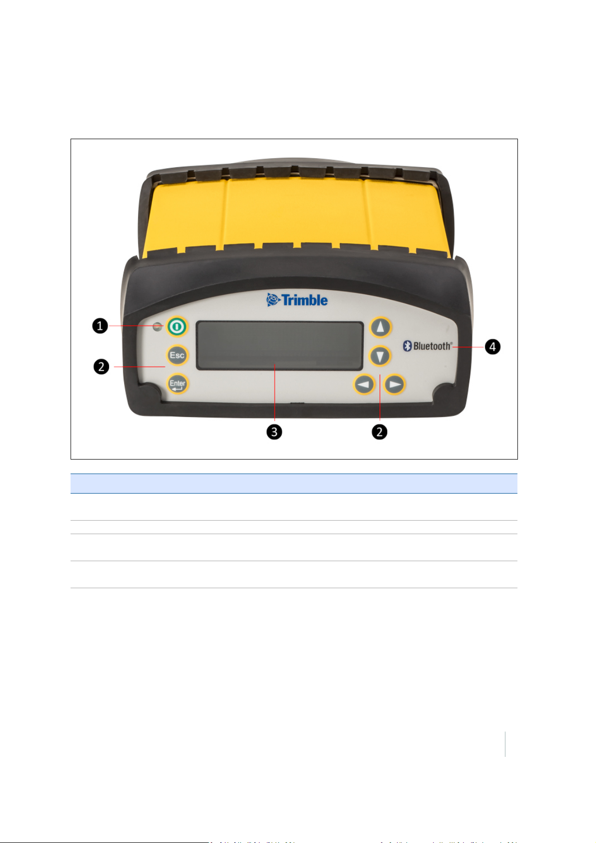
Keypad and display
Item Feature Description
1 Power
LED
2 Buttons Used to turn on and configure the receiver.
3 Display The receiver has a Vacuum Fluorescent Display that enables you to see how the
4 Bluetooth
icon
LED indicates if the receiver is on or off.
receiver is operating and view the configuration settings.
Location of the Bluetooth antenna.
SPS356 Modular GNSS Receiver Getting Started Guide 8
Page 9
Button operations
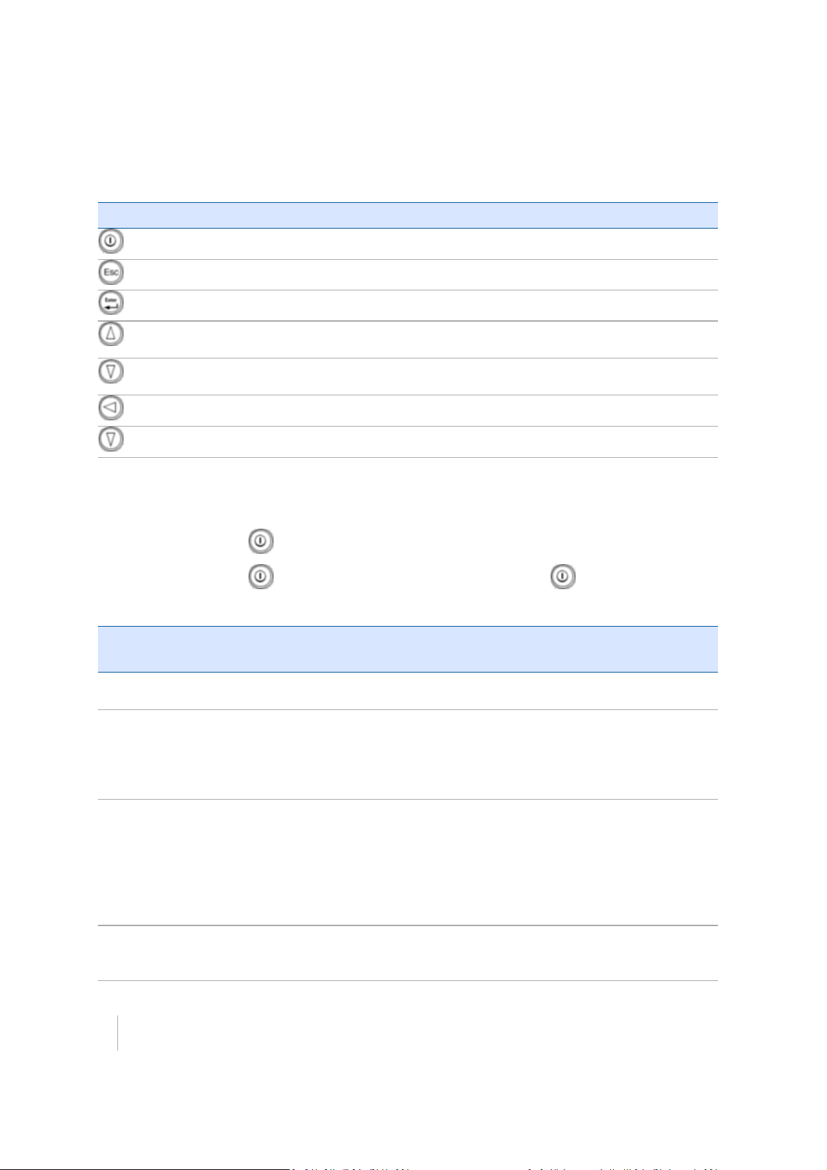
Use the buttons on the front panel to turn the receiver on and off and to check or change the
receiver settings.
Button Name Function
Power
Turns the receiver on and off and performs reset operations.
Escape
Enter
Up
Down
Left
Right
Returns to the previous screen or cancels changes being made on a screen.
Advances to the next screen or accepts changes made on a screen.
Moves the cursor between multiple fields on a screen or makes changes to an
editable field.
Moves the cursor between multiple fields on a screen or makes changes to an
editable field.
Moves the cursor between characters in a field that can be changed.
Moves the cursor between characters in a field that can be changed.
Power button operations
Press the Power button to turn the receiver on and off.
In addition, you can tap to return to the Home screen, or hold down to perform the
following operations:
To... Hold the Power
button for...
turn off the
receiver
clear the
almanac,
ephemeris,
and SV
information
reset the
receiver to
its factory
defaults and
the default
application
file
force the
receiver to
power down
two seconds The display shows a countdown timer. When the display goes
15 seconds The display shows a countdown timer. When the display goes
35 seconds The display shows a countdown timer. When the display goes
at least 60
seconds
Notes
blank, release the Powerbutton.
blank, continue to hold the Power button. The display shows a
countdown time to clear the almanac and ephemeris. When the
counter reaches 0, release the Power button.
blank, continue to hold the Power button. The display show a
countdown to clear the almanac and ephemeris. When the
counter reaches 0, continue to hold the Power button. The display
indicates a countdown to resetting the receiver. When the counter
reaches 0, release the Power button.
If the reset method above does not work, use this method to force
the receiver to turn off. When the Power LED goes off, release the
Power button.
9 SPS356 Modular GNSS Receiver Getting Started Guide
Page 10
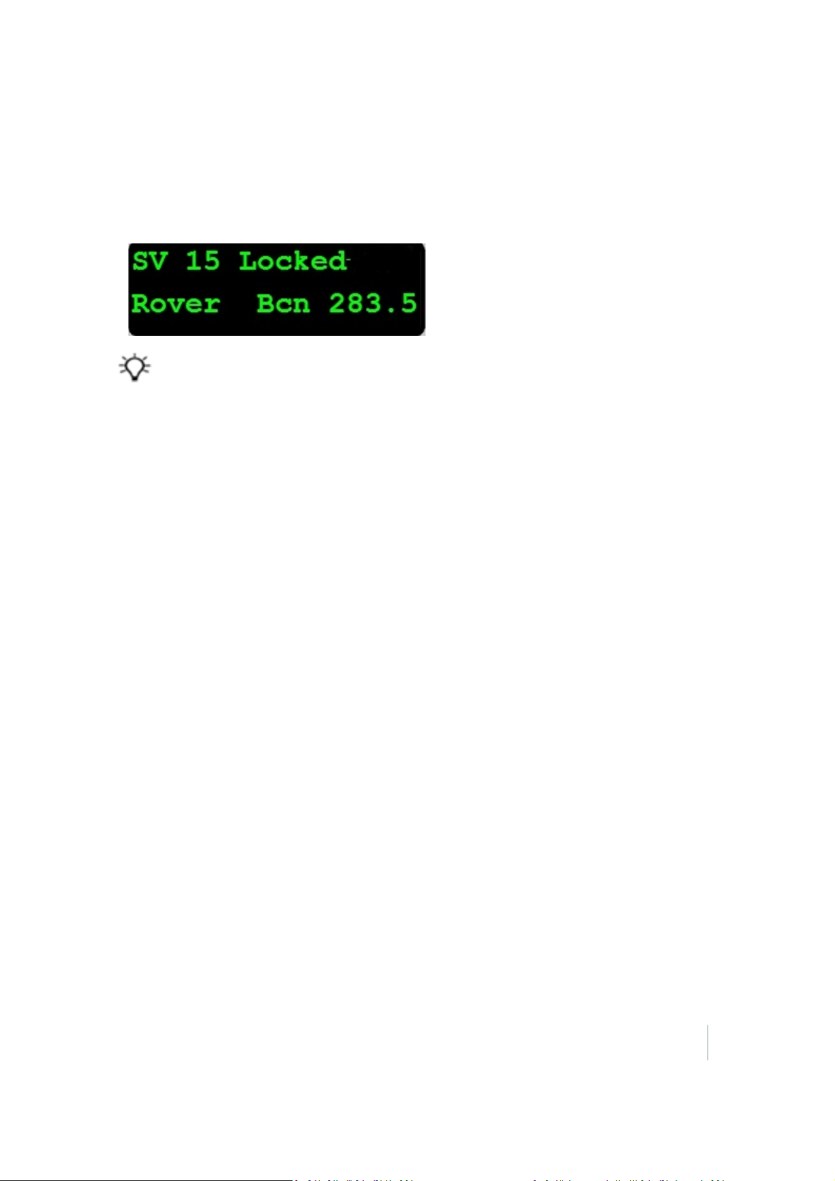
Home screen
The Home screen is the main screen displayed on the receiver. If you briefly press the Power button,
you return to the Home screen. It shows the number of satellites being tracked:
l
When the receiver is in Rover mode, the Home screen displays the number of satellites used to
calculate the position, and the MSK Beacon status (if enabled).
Tip – To view these details using the web interface, select Receiver Status / Position.
SPS356 Modular GNSS Receiver Getting Started Guide 10
Page 11

Status screens
The receiver has several view-only status screens that allow you to review the current settings of the
receiver. The status screens provide the following information:
l
Position solution and 1-sigma precisions
l
CMR and RTCM IDs or OmniSTAR satellite and link status
l
MSK beacon station name, quality and age of corrections
l
Latitude, longitude, and height
l
Antenna height
l
Receiver model, installed precision, and hardware version
l
Receiver firmware version
l
Receiver serial number
l
Receiver IP address
l
Receiver IP address and MAC address for WAN (Wi-Fi client), UAP (Wi-Fi Access point), and ETH
(Wired Ethernet)
To access these screens from the Home screen, press or .
11 SPS356 Modular GNSS Receiver Getting Started Guide
Page 12
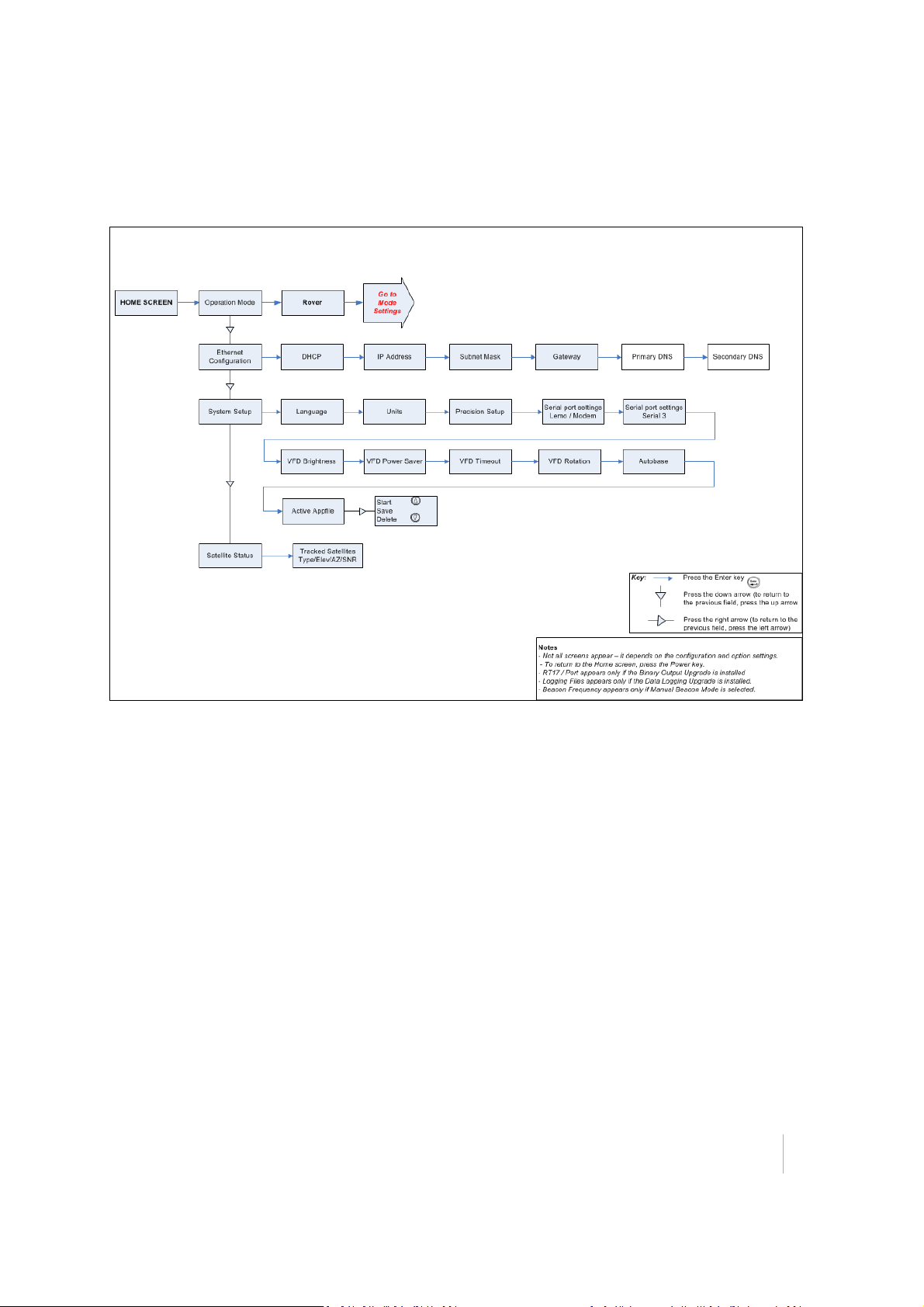
Front Panel Guide
SPS356 configuration screens
SPS356 Modular GNSS Receiver Getting Started Guide 12
Page 13
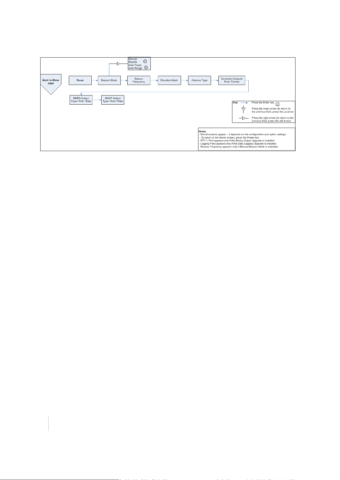
SPS356 mode screens
13 SPS356 Modular GNSS Receiver Getting Started Guide
Page 14
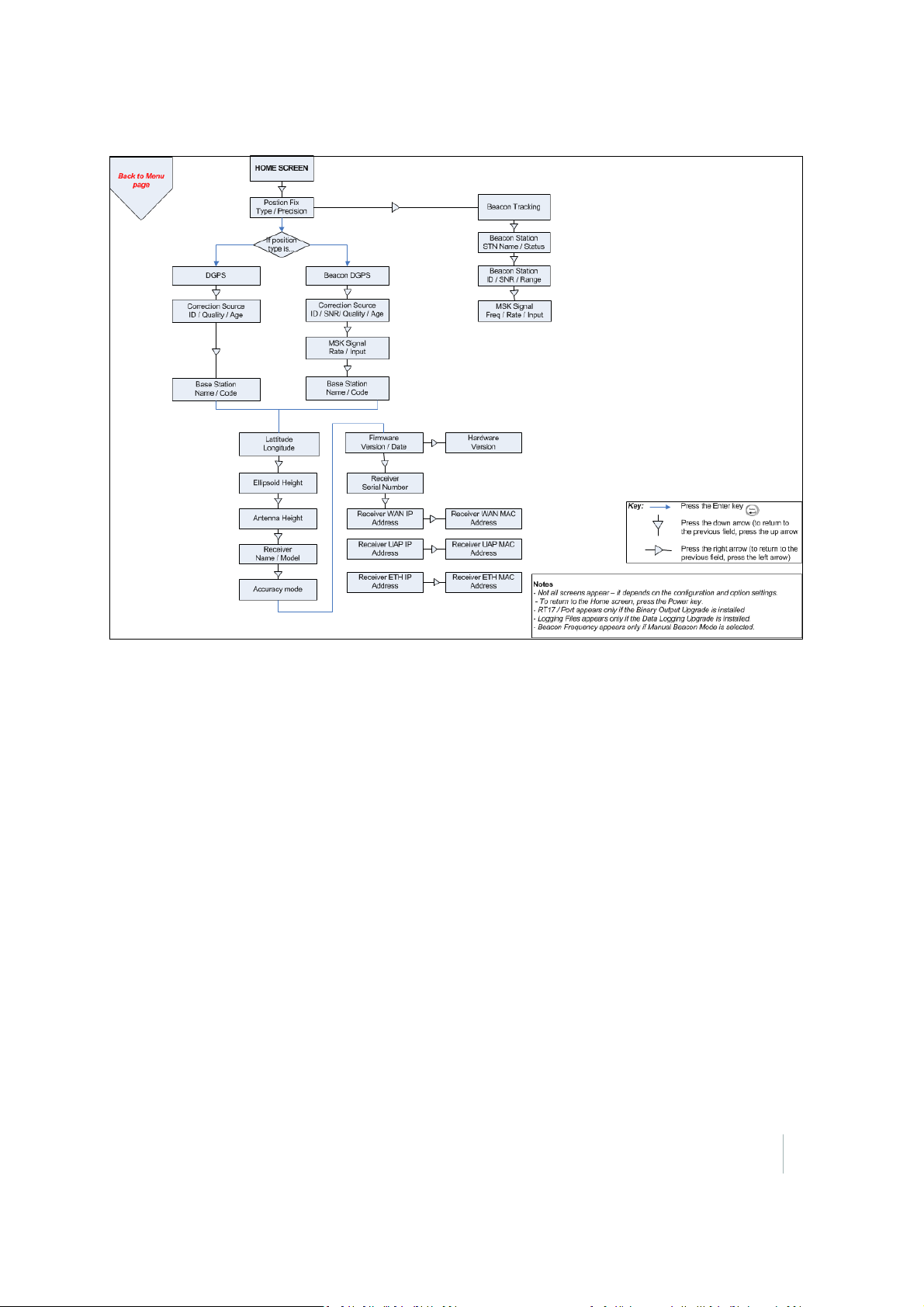
SPS356 status screens
SPS356 Modular GNSS Receiver Getting Started Guide 14
Page 15
Configuring System Settings
You can use the keypad and display of the receiver to configure the following settings:
l
Ethernet configuration
l
Display language
l
Display and input units
l
Baud rate, parity, data bits, and stop bits for serial ports
l
Display power saver, brightness, timeout, and rotation
l
Set position precisions
l
AutoBase and the current application file
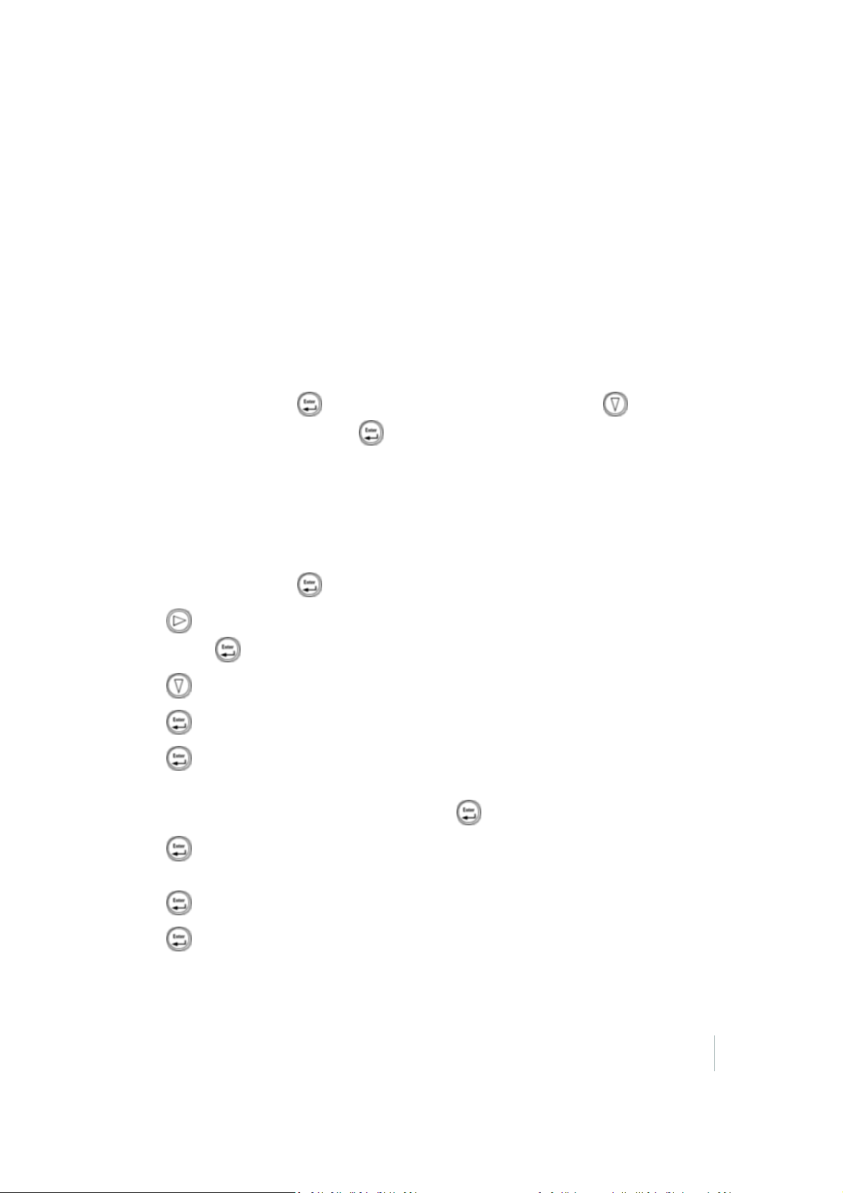
To access the Mode settings:
1.
In the Home screen, press to get to the Operating Mode screen. Press to get to the
appropriate section, and then press to edit:
l l Ethernet Config
l System Setup
l SV Status
To change the system settings:
1.
In the Home screen, press .
2.
Press . When the operation mode begins to flash, the receiver is in Edit mode and you can
change press to change this setting.
3.
Press twice to change to System Setup.
4.
Press to accept the change.
5.
Press again.
6.
Use the Display Language screen, if required, to change the language. Choose English, Finnish,
French, German, Italian, Spanish, or Swedish. Press to accept the change.
7.
Press again. Use the Display and Input Units screen, if required, to change the units to
Meters or US Feet.
8.
Press to accept the change.
9.
Press again. Use the Precision Setup screen, if required, to change the required position
tolerances.
SPS356 Modular GNSS Receiver Getting Started Guide 15
Page 16
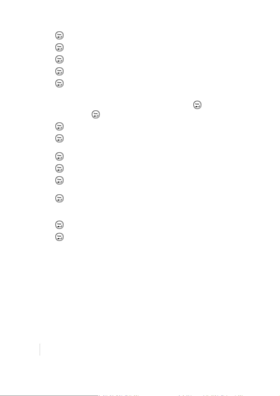
10.
Press to accept the change.
11.
Press again. Use the Port Settings screen, if required, to change the port.
12.
Press to accept the change.
13.
Press again. Use the VFD Brightness screen, if required, to change the display brightness.
14.
Press again. Use the VFD Pwr Savr screen to choose On, Off, or Auto. If you use the Auto
setting, the screen turns off after the timeout period that is set in the next screen. The default
setting is 60 seconds of inactivity. The Power LED remains lit so that you can tell if the receiver is
on or off. If an error message appears, the screen comes back on. Press to accept the
change and then press again to move to the next screen.
15.
Press to accept the change.
16.
Press again. Use the VFD Timeout screen, if required, to set the VFD Power Saver timeout
period.
17.
Press to accept the change.
18.
Press again. Use the VFD Rotation screen, if required, to invert the display.
19.
Press again. By default, the Autobase screen is set to Off as the SPS356 is only a Rover
receiver).
20.
Press again. The Active Appfile screen appears.
To change the application file, press to display START Appfile. Press to show SAVE Appfile.
Press to show DELETE Appfile. Press to show START Appfile.
21.
Press to accept the change.
22.
Press again. When the Home screen appears, the system setup is complete.
16 SPS356 Modular GNSS Receiver Getting Started Guide
Page 17
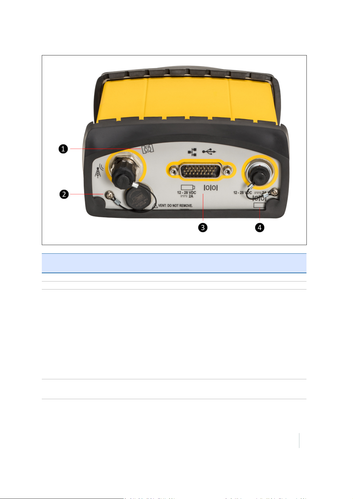
Rear Connectors
Item Connector
Type
1 TNC Connect to the GNSS antenna
2 Vent plug External venting plug for pressure equalization
3 High Density
DB26
4 Lemo
(7-pin/0-shell)
Description
l
Ethernet port 10/100 Base-T network through an RJ45 jack on a multiport
adapter (P/N 57167 or P/N 57168)
l
'Slave' USB port through the USB type B connector on the multiport
adapter (P/N 57167)
l
'Host' USB port through the connector on the 26-pin cable (P/N 58339)
l
Primary power input from an external power supply
l
5-wire RS-232 serial port using various cables
l
1PPS output using breakout cables (P/N 60789-00 or P/N 77070-00)
l
3-wire RS-232 serial port (P/N 65791 or P/N 78235-00)
l
3-wire RS-232 serial port using a 7-pin/ 0 shell Lemo cable
l
Secondary external power input
SPS356 Modular GNSS Receiver Getting Started Guide 17
Page 18

Connecting to a Device
Using Bluetooth wireless technology
By default, the SPS356 Modular GNSS receiver is ‘Discoverable’ and will be listed on your Bluetooth
capable device when you scan for nearby Bluetooth devices. The default Bluetooth device name is in
the format "SPS356 <Serial number>: <System Name>", for example: "SPS356 5436R00074: My
System".
On a Window 7 device, the SPS356 Modular GNSS receiver will appear as a “Network Infrastructure
Device” with an “Access Point” connection. When connected using the “Access Point”, the SPS356
Modular GNSS receiver can be accessed using a web browser on the default IP address of
192.168.143.1.
Using Wi-Fi
By default, the SPS356 Modular GNSS receiver is configured as an Access Point, so you can connect
to it using any Wi-Fi capable device with a standard web browser.
1.
On a Wi-Fi enabled device, search for the SPS356 Modular GNSS receiver SSID which will be in
the format:
“Trimble GNSS 1234” where 1234 are the last 4 digits of the serial number.
2. Connect using the default WEP64 encryption key: abcdeabcde.
3.
Open a web browser on your Wi-Fi enabled device and then type GNSS into the address bar.
Note – With some devices, you may need to enter either http://GNSS or
192.168.142.1 to access the web interface.
4. Log in to the web interface. The default username is admin. The default password is
password.
5. For detailed information on each page, use the Help links in the web interface.
SPS356 Modular GNSS Receiver Getting Started Guide 18
Page 19

Upgrading the Receiver
The SPS356 receiver can be upgraded to track GLONASS, BeiDou, and Galileo single-frequency
satellite signals.
To install an upgrade (option) codes, enter the code supplied by your Trimble Marine dealer into the
Option Code field in the web interface of the receiver.
For more information, refer to the topic "Upgrading the Receiver Firmware" in the Trimble SPS
Modular GNSS Receivers Help.
SPS356 Modular GNSS Receiver Getting Started Guide 19
Page 20
Signal Tracking
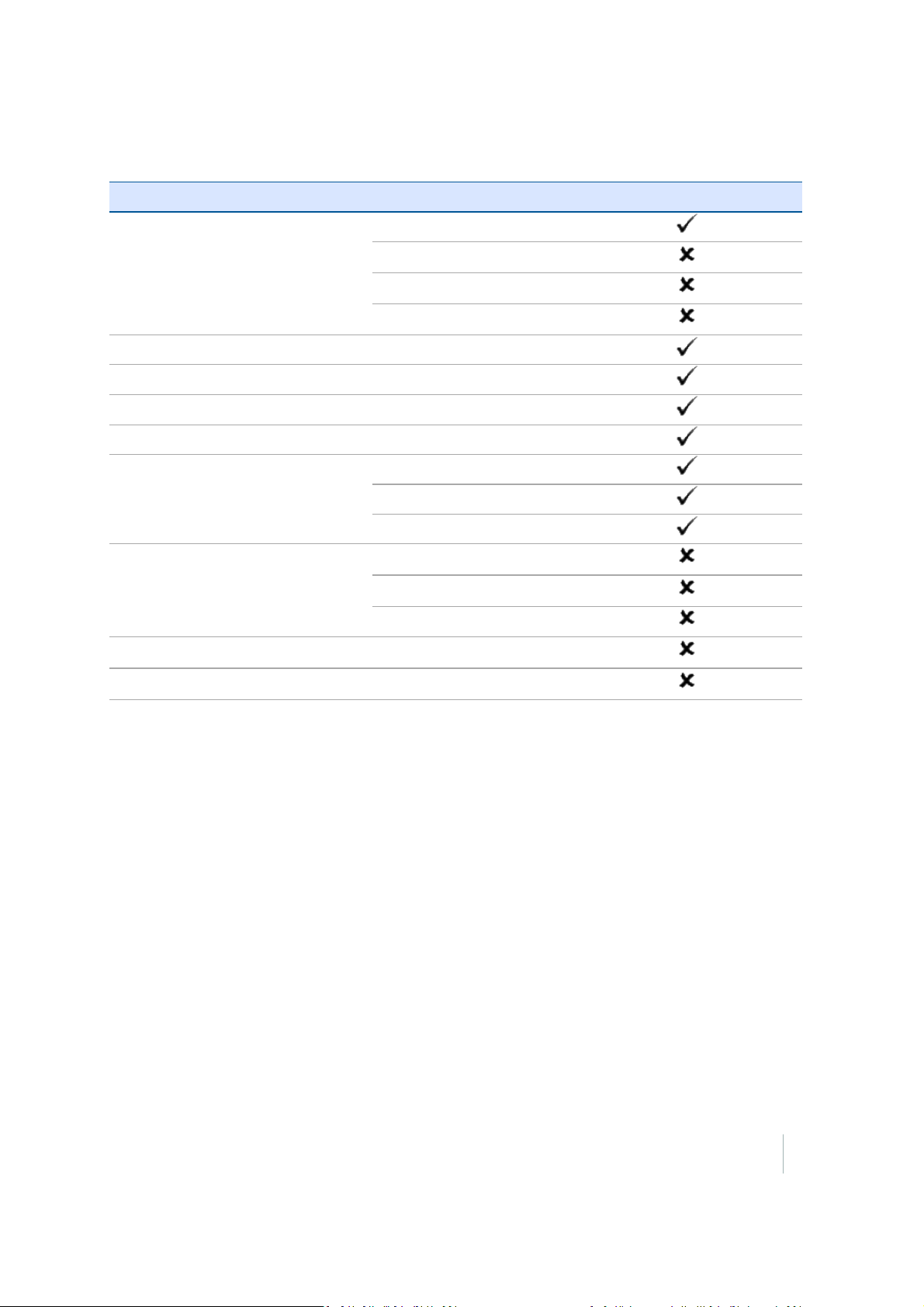
This table shows the signal tracking capability for the receiver:
Signal Type Class SPS356
GPS signals L1
L2
L2C
L5
QZSS L1 C/A, L1C, L1 SAIF
GLONASS signals L1
Galileo L1
BeiDou B1
SBAS corrections WAAS
EGNOS
MSAS
OmniSTAR XP
HP
VBS
RTX CenterPoint
xFill xFill
SPS356 Modular GNSS Receiver Getting Started Guide 20
Page 21
Managing Application Files
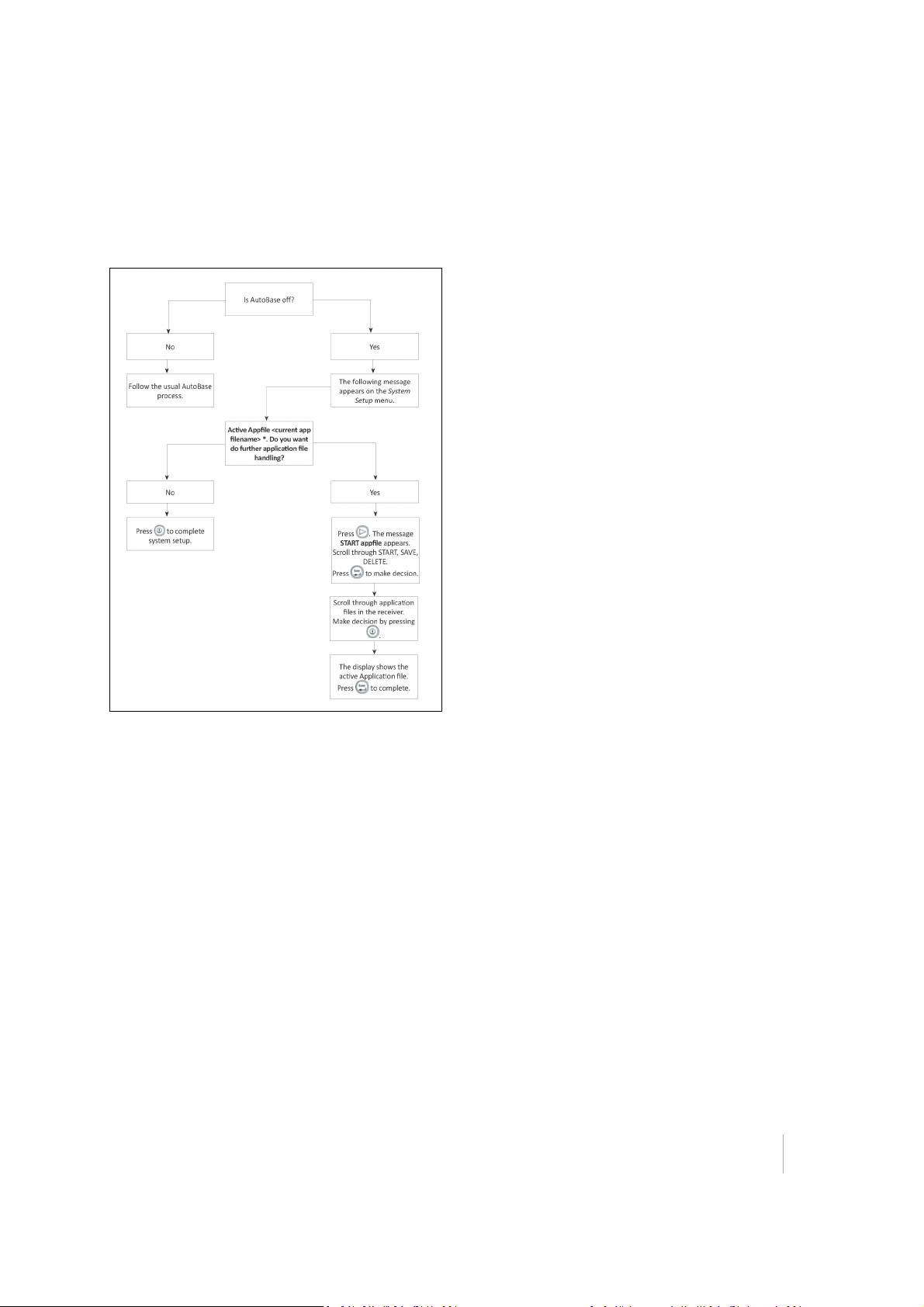
You can use the front panel to manage application files in the receiver. You can see which
application file the receiver is currently using and then choose to make changes to it and save it,
load a different application file, or delete an application file.
To manage the application files, use the System Setup menu (see the figure below).
The following figure shows how application files are handled through the front panel of the receiver:
SPS356 Modular GNSS Receiver Getting Started Guide 21
Page 22

Default behavior
If a power-up application file is present in the receiver, its settings are applied immediately after the
default settings. This means you can use a power-up file to define your own set of defaults. The
factory defaults are also applied when you perform a full reset of the receiver because resetting the
receiver deletes the power-up files.
When starting any of the SPS receivers as rover receiver using the HYDROpro Construction software,
the settings required for those operations are automatically set and configured in that software. To
change the receiver settings for special applications or for use with third-party software, use the web
interface.
The SPS356 web browser interface can be accessed by connecting to its Wi-Fi Access Point using any
Wi-Fi capable device with a web browser.
22 SPS356 Modular GNSS Receiver Getting Started Guide
Page 23

Resetting the receiver to factory defaults
To reset the receiver to its factory defaults, do one of the following:
l
Press for 15 seconds.
l
In the GPS Configurator software, select Connect to Receiver and then click Reset Receiver in
the General tab.
l
In the Configuration Toolbox software, select the General tab and then click Reset Receiver.
For more information on the GPS Configurator and Configuration Toolbox software, refer to the
"Configuring the Receiver Settings" section of the Trimble SPS Series Receiver Help.
SPS356 Modular GNSS Receiver Getting Started Guide 23
Page 24

Glossary
1PPS
almanac
base station
BeiDou
broadcast server
carrier
carrier frequency
carrier phase
cellular modems
CMR/CMR+
CMRx
Pulse-per-second. Used in hardware timing. A pulse is generated in conjunction
with a time stamp. This defines the instant when the time stamp is applicable.
A file that contains orbit information on all the satellites, clock corrections, and
atmospheric delay parameters. The almanac is transmitted by a GNSS satellite to a
GNSS receiver, where it facilitates rapid acquisition of GNSS signals when you start
collecting data, or when you have lost track of satellites and are trying to regain
GNSS signals.
The orbit information is a subset of the ephemeris/ephemerides data.
Also called reference station. In construction, a base station is a receiver placed at a
known point on a jobsite that tracks the same satellites as an RTK rover, and
provides a real-time differential correction message stream through radio to the
rover, to obtain centimeter level positions on a continuous real-time basis. A base
station can also be a part of a virtual reference station network, or a location at
which GNSS observations are collected over a period of time, for subsequent
postprocessing to obtain the most accurate position for the location.
The BeiDou Navigation Satellite System (also known as BDS ) is a Chinese satellite
navigation system.
The first BeiDou system (known as BeiDou-1), consists of four satellites and has
limited coverage and applications. It has been offering navigation services mainly
for customers in China and from neighboring regions since 2000.
The second generation of the system (known as BeiDou-2) consists of satellites in a
combination of geostationary, inclined geosynchronous, and medium earth orbit
configurations. It became operational with coverage of China in December 2011.
However, the complete Interface Control Document (which specifies the satellite
messages) was not released until December 2012. BeiDou-2 is a regional navigation
service which offers services to customers in the Asia-Pacific region.
A third generation of the BeiDou system is planned, which will expand coverage
globally. This generation is currently scheduled to be completed by 2020.
An Internet server that manages authentication and password control for a network
of VRS servers, and relays VRS corrections from the VRS server that you select.
A radio wave having at least one characteristic (such as frequency, amplitude, or
phase) that can be varied from a known reference value by modulation.
The frequency of the unmodulated fundamental output of a radio transmitter. The
GPS L1 carrier frequency is 1575.42 MHz.
Is the cumulative phase count of the GPS or GLONASS carrier signal at a given time.
A wireless adapter that connects a laptop computer to a cellular phone system for
data transfer. Cellular modems, which contain their own antennas, plug into a PC
Card slot or into the USB port of the computer and are available for a variety of
wireless data services such as GPRS.
Compact Measurement Record. A real-time message format developed by Trimble
for broadcasting corrections to other Trimble receivers. CMR is a more efficient
alternative to RTCM.
A real-time message format developed by Trimble for transmitting more satellite
corrections resulting from more satellite signals, more constellations, and more
satellites. Its compactness means more repeaters can be used on a site.
SPS356 Modular GNSS Receiver Getting Started Guide 24
Page 25

covariance
datum
deep discharge
DGPS
differential correction
differential GPS
DOP
dual-frequency GPS
EGNOS
elevation
elevation mask
A statistical measure of the variance of two random variables that are observed or
measured in the same mean time period. This measure is equal to the product of
the deviations of corresponding values of the two variables from their respective
means.
Also called geodetic datum. A mathematical model designed to best fit the geoid,
defined by the relationship between an ellipsoid and, a point on the topographic
surface, established as the origin of the datum. World geodetic datums are typically
defined by the size and shape of an ellipsoid and the relationship between the
center of the ellipsoid and the center of the earth.
Because the earth is not a perfect ellipsoid, any single datum will provide a better
model in some locations than in others. Therefore, various datums have been
established to suit particular regions.
For example, maps in Europe are often based on the European datum of 1950 (ED-
50). Maps in the United States are often based on the North American datum of
1927 (NAD-27) or 1983 (NAD-83).
All GPS coordinates are based on the WGS-84 datum surface.
Withdrawal of all electrical energy to the end-point voltage before the cell or
battery is recharged.
See real-time differential GPS.
Differential correction is the process of correcting GNSS data collected on a rover
with data collected simultaneously at a base station. Because the base station is on a
known location, any errors in data collected at the base station can be measured,
and the necessary corrections applied to the rover data.
Differential correction can be done in real-time, or after the data is collected by
postprocessing.
See real-time differential GPS.
Dilution of Precision. A measure of the quality of GNSS positions, based on the
geometry of the satellites used to compute the positions. When satellites are
widely spaced relative to each other, the DOP value is lower, and position precision
is greater. When satellites are close together in the sky, the DOP is higher and GNSS
positions may contain a greater level of error.
PDOP (Position DOP) indicates the three-dimensional geometry of the satellites.
Other DOP values include HDOP(Horizontal DOP) and VDOP (Vertical DOP), which
indicate the precision of horizontal measurements (latitude and longitude) and
vertical measurements respectively. PDOP is related to HDOP and VDOP as follows:
PDOP² = HDOP² + VDOP².
A type of receiver that uses both L1 and L2 signals from GPS satellites. A dualfrequency receiver can compute more precise position fixes over longer distances
and under more adverse conditions because it compensates for ionospheric delays.
European Geostationary Navigation Overlay Service. A Satellite-Based
Augmentation System (SBAS) that provides a free-to-air differential correction
service for GNSS. EGNOS is the European equivalent of WAAS, which is available in
the United States.
The vertical distance from a geoid such as EGM96 to the antenna phase center. The
geoid is sometimes referred to as Mean Sea Level.
The angle below which the receiver will not track satellites. Normally set to 10
degrees to avoid interference problems caused by buildings and trees, atmospheric
SPS356 Modular GNSS Receiver Getting Started Guide 25
Page 26

ellipsoid
EHT
ephemeris/ephemerides
epoch
feature
firmware
Galileo
geoid
GHT
GLONASS
GNSS
GSOF
HDOP
height
IBSS
L1
L2
issues, and multipath errors.
An ellipsoid is the three-dimensional shape that is used as the basis for
mathematically modeling the earth’s surface. The ellipsoid is defined by the lengths
of the minor and major axes. The earth’s minor axis is the polar axis and the major
axis is the equatorial axis.
Height above ellipsoid.
A list of predicted (accurate) positions or locations of satellites as a function of time.
A set of numerical parameters that can be used to determine a satellite’s position.
Available as broadcast ephemeris or as postprocessed precise ephemeris.
The measurement interval of a GNSS receiver. The epoch varies according to the
measurement type: for real-time measurement it is set at one second; for
postprocessed measurement it can be set to a rate of between one second and
one minute. For example, if data is measured every 15 seconds, loading data using
30-second epochs means loading every alternate measurement.
A feature is a physical object or event that has a location in the real world, which
you want to collect position and/or descriptive information (attributes) about.
Features can be classified as surface or non-surface features, and again as points,
lines/break lines, or boundaries/areas.
The program inside the receiver that controls receiver operations and hardware.
Galileo is a GNSS system built by the European Union and the European Space
Agency. It is complimentary to GPS and GLONASS.
The geoid is the equipotential surface that would coincide with the mean ocean
surface of the Earth. For a small site this can be approximated as an inclined plane
above the Ellipsoid.
Height above geoid.
Global Orbiting Navigation Satellite System. GLONASS is a Soviet space-based
navigation system comparable to the American GPS system. The operational system
consists of 21 operational and 3 non-operational satellites in 3 orbit planes.
Global Navigation Satellite System.
General Serial Output Format. A Trimble proprietary message format.
Horizontal Dilution of Precision. HDOP is a DOP value that indicates the precision of
horizontal measurements. Other DOP values include VDOP (vertical DOP) and
PDOP (Position DOP).
Using a maximum HDOP is ideal for situations where vertical precision is not
particularly important, and your position yield would be decreased by the vertical
component of the PDOP (for example, if you are collecting data under canopy).
The vertical distance above the Ellipsoid. The classic Ellipsoid used in GPS is WGS-
84.
Internet Base Station Service. This Trimble service makes the setup of an Internet-
capable receiver as simple as possible. The base station can be connected to the
Internet (cable or wirelessly). To access the distribution server, the user enters a
password into the receiver. To use the server, the user must have a Trimble
Connected Community site license.
The primary L-band carrier used by GPS and GLONASS satellites to transmit satellite
data.
The secondary L-band carrier used by GPS and GLONASS satellites to transmit
satellite data.
SPS356 Modular GNSS Receiver Getting Started Guide 26
Page 27

L2C
L5
Mountpoint
MSAS
multipath
NMEA
NTrip Protocol
NTripCaster
NTripClient
NTripServer
NTripSource
OmniSTAR
Orthometric elevation
A modernized code that allows significantly better ability to track the L2 frequency.
The third L-band carrier used by GPS satellites to transmit satellite data. L5 will
provide a higher power level than the other carriers. As a result, acquiring and
tracking weak signals will be easier.
Every single NTripSource needs a unique mountpoint on an NTripCaster. Before
transmitting GNSS data to the NTripCaster, the NTripServer sends an assignment of
the mountpoint.
MTSAT Satellite-Based Augmentation System. A Satellite-Based Augmentation
System (SBAS) that provides a free-to-air differential correction service for GNSS.
MSAS is the Japanese equivalent of WAAS, which is available in the United States.
Interference, similar to ghosts on an analog television screen, which occurs when
GNSS signals arrive at an antenna having traversed different paths. The signal
traversing the longer path yields a larger pseudorange estimate and increases the
error. Multiple paths can arise from reflections off the ground or off structures
near the antenna.
National Marine Electronics Association. NMEA 0183 defines the standard for
interfacing marine electronic navigational devices. This standard defines a number
of 'strings' referred to as NMEA strings that contain navigational details such as
positions. Most Trimble GNSS receivers can output positions as NMEA strings.
Networked Transport of RTCM via Internet Protocol (NTrip) is an application-level
protocol that supports streaming Global Navigation Satellite System (GNSS) data
over the Internet. NTrip is a generic, stateless protocol based on the Hypertext
Transfer Protocol (HTTP). The HTTP objects are extended to GNSS data streams.
The NTripCaster is basically an HTTP server supporting a subset of HTTP
request/response messages and adjusted to low-bandwidth streaming data. The
NTripCaster accepts request messages on a single port from either the NTripServer
or the NTripClient. Depending on these messages, the NTripCaster decides whether
there is streaming data to receive or to send.
Trimble NTripCaster integrates the NTripServer and the NTripCaster. This port is
used only to accept requests from NTripClients.
An NTripClient will be accepted by and receive data from an NTripCaster, if the
NTripClient sends the correct request message (TCP/UDP connection to the
specified NTripCaster IP and listening port).
The NTripServer is used to transfer GNSS data of an NTripSource to the NTripCaster.
An NTripServer in its simplest setup is a computer program running on a PC that
sends correction data of an NTripSource (for example, as received through the
serial communication port from a GNSS receiver) to the NTripCaster.
The NTripServer - NTripCaster communication extends HTTP by additional message
formats and status codes.
The NTripSources provide continuous GNSS data (for example, RTCM-104
corrections) as streaming data. A single source represents GNSS data referring to a
specific location. Source description parameters are compiled in the source-table.
The OmniSTAR HP/XP service allows the use of new generation dual-frequency
receivers with the OmniSTAR service. The HP/XP service does not rely on local
reference stations for its signal, but utilizes a global satellite monitoring network.
Additionally, while most current dual-frequency GNSS systems are accurate to
within a meter or so, OmniSTAR with XP is accurate in 3D to better than 30 cm.
The Orthometric Elevation is the height above the geoid (often termed the height
SPS356 Modular GNSS Receiver Getting Started Guide 27
Page 28

PDOP
postprocessing
QZSS
real-time differential
GPS
rover
Roving mode
RTCM
RTK
SBAS
signal-to-noise ratio
skyplot
SNR
Source-table
above the 'Mean Sea Level').
Position Dilution of Precision. PDOP is a DOP value that indicates the precision of
three-dimensional measurements. Other DOP values include VDOP (vertical DOP)
and HDOP (Horizontal Dilution of Precision).
Using a maximum PDOP value is ideal for situations where both vertical and
horizontal precision are important.
Postprocessing is the processing of satellite data after it is collected, in order to
eliminate error. This involves using computer software to compare data from the
rover with data collected at the base station.
Quasi-Zenith Satellite System. A Japanese regional GNSS eventually consisting of
three geosynchronous satellites over Japan.
Also known as real-time differential correction or DGPS. Real-time differential GPS is
the process of correcting GPS data as you collect it. Corrections are calculated at a
base station and then sent to the receiver through a radio link. As the rover
receives the position it applies the corrections to give you a very accurate position
in the field.
Most real-time differential correction methods apply corrections to code phase
positions.
While DGPS is a generic term, its common interpretation is that it entails the use of
single-frequency code phase data sent from a GNSS base station to a rover GNSS
receiver to provide sub-meter position. The rover receiver can be at a long range
(greater than 100 kms (62 miles)) from the base station.
A rover is any mobile GNSS receiver that is used to collect or update data in the
field, typically at an unknown location.
Roving mode applies to the use of a rover receiver to collect data, stakeout, or
control earthmoving machinery in real time using RTK techniques.
Radio Technical Commission for Maritime Services. A commission established to
define a differential data link for the real-time differential correction of roving
GNSS receivers. There are three versions of RTCM correction messages. All Trimble
GNSS receivers use Version 2 protocol for single-frequency DGPS type corrections.
Carrier phase corrections are available on Version 2, or on the newer Version 3
RTCM protocol, which is available on certain Trimble dual-frequency receivers. The
Version 3 RTCM protocol is more compact but is not as widely supported as Version
2.
real-time kinematic. A real-time differential GPS method that uses carrier
phasemeasurements for greater.
Satellite-Based Augmentation System. SBAS is based on differential GPS, but applies
to wide area (WAAS/EGNOS/MSAS) networks of reference stations. Corrections
and additional information are broadcast using geostationary satellites.
SNR. The signal strength of a satellite is a measure of the information content of the
signal, relative to the signal’s noise. The typical SNR of a satellite at 30° elevation is
between 47 and 50 dBHz.
The satellite skyplot confirms reception of a differentially corrected GNSS signal and
displays the number of satellites tracked by the GNSS receiver, as well as their
relative positions.
See signal-to-noise ratio.
The NTripCaster maintains a source-table containing information on available
SPS356 Modular GNSS Receiver Getting Started Guide 28
Page 29

triple frequency GPS
UTC
xFill
VRS
WAAS
WGS-84
NTripSources, networks of NTripSources, and NTripCasters, to be sent to an
NTripClient on request. Source-table records are dedicated to one of the following:
l
data STReams (record type STR)
l
CASters (record type CAS)
l
NETworks of data streams (record type NET)
All NTripClients must be able to decode record type STR. Decoding types CAS and
NET is an optional feature. All data fields in the source-table records are separated
using the semicolon character.
A type of receiver that uses three carrier phase measurements (L1, L2, and L5).
Universal Time Coordinated. A time standard based on local solar mean time at the
Greenwich meridian.
Trimble xFill™ is a new service that extends RTK positioning for several minutes
when the RTK correction stream is temporarily unavailable. The Trimble xFill
service improves field productivity by reducing downtime waiting to re-establish
RTK corrections in black spots. It can even expand productivity by allowing short
excursions into valleys and other locations where continuous correction messages
were not previously possible. Proprietary Trimble xFill corrections are broadcast by
satellite and are generally available on construction sites globally where the GNSS
constellations are also visible. It applies to any positioning task being performed
with a single-base, Trimble Internet Base Station Service (IBSS), or VRS™ RTK
correction source.
Virtual Reference Station. A VRS system consists of GNSS hardware, software, and
communication links. It uses data from a network of base stations to provide
corrections to each rover that are more accurate than corrections from a single
base station.
To start using VRS corrections, the rover sends its position to the VRS server. The
VRS server uses the base station data to model systematic errors (such as
ionospheric noise) at the rover position. It then sends RTCM correction messages
back to the rover.
Wide Area Augmentation System. WAAS was established by the Federal Aviation
Administration (FAA) for flight and approach navigation for civil aviation. WAAS
improves the accuracy and availability of the basic GNSS signals over its coverage
area, which includes the continental United States and outlying parts of Canada and
Mexico.
The WAAS system provides correction data for visible satellites. Corrections are
computed from ground station observations and then uploaded to two
geostationary satellites. This data is then broadcast on the L1 frequency, and is
tracked using a channel on the GNSS receiver, exactly like a GNSS satellite.
Use WAAS when other correction sources are unavailable, to obtain greater
accuracy than autonomous positions. For more information on WAAS, refer to the
FAA website at http://gps.faa.gov.
The EGNOS service is the European equivalent and MSAS is the Japanese equivalent
of WAAS.
World Geodetic System 1984. Since January 1987, WGS-84 has superseded
WGS-72 as the datum used by GPS.
The WGS-84 datum is based on the ellipsoid of the same name.
SPS356 Modular GNSS Receiver Getting Started Guide 29
 Loading...