

Page 1

INSTALLATION GUIDE
Trimble® SNM940 Connected Site® Gateway
For a more detailed description of the installation process, please refer to the Installation Guide. Please visit
partners.trimble.com and select SNM940 Technical Support / SNM940 Connected Site Gateway Documentation.
Version 4.00
Revision A
October 2012
Page 2

Corporate Office
Trimble Navigation Limited
935 Stewart Drive
PO Box 3642
Sunnyvale, CA 94085
USA
www.trimble.com
Heavy Civil Construction
Trimble Navigation Limited
10355 Westmoor Drive, Bldg. 100
Westminster, CO 80021
USA
800-538-7800 (toll free in USA)
+1-937-245-5600 Phone
+1-937-233-9004 Fax
www.trimble.com
Legal Notices
Copyright and Trademarks
© 2012, Trimble Navigation Limited. All rights reserved.
Trimble, the Globe & Triangle logo, and Connected Site are
trademarks of Trimble Navigation Limited, registered in the United
States and in other countries. VisionLink is a trademark of Trimble
Navigation Limited.
Microsoft and Windows are either registered trademarks or
trademarks of Microsoft Corporation in the United States and/or
other countries. All other trademarks are the property of their
respective owners.
Release Notice
This is the October 2012 release (Revision A) of the SNM940
Connected Site Gateway Installation Guide. It applies to version
4.00 of the SNM940 Connected Site Gateway.
Limited Warranty Terms and Conditions
See Limited Warranty Terms and Conditions, page 47.
Software Components Notices
See Software Components, page 48.
Notices
Trimble SNM940 CDMA
FCC Identifier: JUP-WCDCM300C contains FCC ID N7N-MC5728
Trimble DCM300C complies with FCC radiation exposure limits set
forth for an occupational/controlled environment. This equipment
should be operated with a minimum distance of 20cm between
the radiator and your body.
The marketed product name is SNM940. The model name is
DCM300C.
The CDMA variant of the SNM940 is certified for use with the
following Trimble antennas:
– Bulkhead GPS/Cellular - 83154, 84398
– Adhesive-mount GPS/Cellular - 82654-HH
– Bulkhead wireless LAN - 83155, 84277
Trimble SNM940 GSM
FCC Identifier: JUP-WCDCM300G contains FCC ID QIPHC25
Trimble DCM300G complies with FCC radiation exposure limits set
forth for an occupational/controlled environment. This equipment
should be operated with a minimum distance of 20 cm between
the radiator and your body.
The marketed product name is SNM940. The model name is
DCM300G.
The GSM variant of the SNM940 is certified for use with the
following Trimble antennas:
– Bulkhead GPS/Cellular - 83154, 84398
– Adhesive-mount GPS/Cellular - 82654-HH
– Bulkhead wireless LAN - 83155, 84277
For GSM850 and PCS1900 operation, in order to maintain
compliance with FCC RF exposure requirements, antennas with
gains plus cable losses not exceeding 5.0dBi (850 MHz and 4.7 dBi
(1900MHz) must be used.
Additional Regulatory Conformance
This product has successfully completed the PTCRB requirements
governing the release of new GSM 850/900/1800/1900 capable
products into the global market.
Regulatory Installation Guidance
Chassis ground is a required connection to reduce
electromagnetic interference. The preferred chassis grounding is
through the mounting bolts to the vehicle chassis. A chassis
ground strap to the vehicle’s metal frame is the next best
alternative when the immediate mounting surface is nonconductive.
Antenna Electrical Isolation – The antenna housing must not be
connected to chassis ground.
Class B Statement – Notice to Users
This equipment has been tested and found to comply with the
limits for a Class B digital device, pursuant to Part 15 of the FCC
rules. These limits are designed to provide reasonable protection
against harmful interference in a residential installation. This
equipment generates, uses, and can radiate radio frequency
energy and, if not installed and used in accordance with the
instructions, may cause harmful interference to radio
communication. However, there is no guarantee that interference
will not occur in a particular installation. If this equipment does
cause harmful interference to radio or television reception, which
can be determined by turning the equipment off and on, the user
is encouraged to try to correct the interference by one or more of
the following measures:
– Reorient or relocate the receiving antenna.
– Increase the separation between the equipment and the receiver.
– Connect the equipment into an outlet on a circuit different from
that to which the receiver is connected.
– Consult the dealer or an experienced radio/TV technician for help.
Changes and modifications not expressly approved by the
manufacturer or registrant of this equipment can void your
authority to operate this equipment under Federal
Communications Commission rules.
Canada
This Class B digital apparatus complies with Canadian ICES-003.
Cet appareil numérique de la classe B est conforme à la norme
ICES-003 du Canada.
I Pour DCM300G:
Trimble DCM300G conforme à l'exposition de l'industrie
rayonnement Canada limites établies pour un travail /
environnement contrôlé. Cet équipement doit être utilisé avec
une distance minimale de 20 cm entre le radiateur et votre corps.
Trimble DCM300G est certifié pour une utilisation avec les
antennes suivantes:
– Bulkhead GPS/Cellular - 83154, 84398
– Adhesive-mount GPS/Cellular - 82654-HH
– Bulkhead wireless LAN - 83155, 84277
Pour un fonctionnement GSM850 et PCS1900, afin de maintenir la
conformité aux exigences d'exposition aux RF IC, les antennes avec
des gains et des pertes de câble dépassant pas 8.7dBi (850MHz) et
4.4dBi (1900MHz) doit être utilisé.
Types d'antennes sont approuvés:
– Bulkhead GPS/Cellular - 83154, 84398
– Adhesive-mount GPS/Cellular - 82654-HH
– Bulkhead wireless LAN - 83155, 84277
Trimble DCM300G complies with Industry Canada licence-exempt
RSS standard(s). Operation is subject to the following two
conditions: (1) this device may not cause interference, and (2) this
device must accept any interference, including interference that
may cause undesired operation of the device.
Le présent appareil est conforme aux CNR d'Industrie Canada
applicables aux appareils radio exempts de licence. L'exploitation
est autorisée aux deux conditions suivantes : (1) l'appareil ne doit
pas produire de brouillage, et (2) l'utilisateur de l'appareil doit
accepter tout brouillage radioélectrique subi, même si le
brouillage est susceptible d'en compromettre le fonctionnement.
Under Industry Canada regulations, this radio transmitter may
only operate using an antenna of a type and maximum (or lesser)
gain approved for the transmitter by Industry Canada. To reduce
potential radio interference to other users, the antenna type and
its gain should be so chosen that the equivalent isotropically
radiated power (e.i.r.p.) is not more than that necessary for
successful communication.
SNM940 CONNECTED SITE GATEWAY INSTALLATION GUIDE
2
Page 3
Conformément à la réglementation d'Industrie Canada, le présent
Declaration of Conformity
We, Trimble Navigation Limited,
935 Stewart Drive
PO Box 3642
Sunnyvale, CA 94088-3642
United States
+1-408-481-8000
declare under sole responsibility that the product:
DCM300
complies with Part 15 of FCC Rules.
Operation is subject to the following two conditions:
(1) this device may not cause harmful interference, and
(2) this device must accept any interference received, including
interference that may cause undesired operation.
émetteur radio peut fonctionner avec une antenne d'un type et
d'un gain maximal (ou inférieur) approuvé pour l'émetteur par
Industrie Canada. Dans le but de réduire les risques de brouillage
radioélectrique à l'intention des autres utilisateurs, il faut choisir
le type d'antenne et son gain de sorte que la puissance isotrope
rayonnée équivalente (p.i.r.e.) ne dépasse pas l'intensité
nécessaire à l'établissement d'une communication satisfaisante.
This radio transmitter 1756A-DCM300G has been approved by
Industry Canada to operate with the antenna types listed below
with the maximum permissible gain and required antenna
impedance for each antenna type indicated. Antenna types not
included in this list, having a gain greater than the maximum gain
indicated for that type, are strictly prohibited for use with this
device.
Le présent émetteur radio 1756A-DCM300G a été approuvé par
Industrie Canada pour fonctionner avec les types d'antenne
énumérés ci-dessous et ayant un gain admissible maximal et
l'impédance requise pour chaque type d'antenne. Les types
d'antenne non inclus dans cette liste, ou dont le gain est supérieur
au gain maximal indiqué, sont strictement interdits pour
l'exploitation de l'émetteur.
Industry Canada Identifier: 1756A-DCM300G
Europe
The GSM variant of this product is intended to
be used in all EU member countries. This
product has been tested and found to comply
with the requirements for a Class B device
pursuant to
thereby satisfying the requirements for CE Marking and sale
within the European Economic Area (EEA). These requirements
are designed to provide reasonable protection against harmful
interference when the equipment is operated in a residential or
commercial environment.
R&TTE Directive 1999/5/EC
Hereby, Trimble Navigation declares that the DCM300 devices are
in compliance with the essential requirements and other relevant
provisions of R&TTE Directive 1999/5/EC.
European Council Directive 89/336/EEC on EMC,
Notice to Our European Union Customers
For product recycling instructions and more information, please
go to www.trimble.com/ev.shtml.
Recycling in Europe: To recycle Trimble WEEE (Waste
Electrical and Electronic Equipment, products that run on
electrical power.), Call +31 497 53 24 30, and ask for the
"WEEE Associate". Or, mail a request for recycling
instructions to:
Trimble Europe BV
c/o Menlo Worldwide Logistics
Meerheide 45
5521 DZ Eersel, NL
SNM940 CONNECTED SITE GATEWAY INSTALLATION GUIDE
3
Page 4

Contents
Contents. . . . . . . . . . . . . . . . . . . . . . . . . . . . . . . . . . . . . . . . . . . 4
Safety Information . . . . . . . . . . . . . . . . . . . . . . . . . . . . . . . . . . . . . 6
Installing antennas. . . . . . . . . . . . . . . . . . . . . . . . . . . . . . . . . . . . . . . . . . . . . . . . 6
Wiring notices . . . . . . . . . . . . . . . . . . . . . . . . . . . . . . . . . . . . . . . . . . . . . . . . . . 6
Overall wiring configurations . . . . . . . . . . . . . . . . . . . . . . . . . . . . . . . . . . . . . . . . . . 7
Correct wiring for a negative master disconnect . . . . . . . . . . . . . . . . . . . . . . . . . . . . . 7
Correct wiring for a positive master disconnect. . . . . . . . . . . . . . . . . . . . . . . . . . . . . . 7
1 Introduction. . . . . . . . . . . . . . . . . . . . . . . . . . . . . . . . . . . . . . . . . 8
About the SNM940 device . . . . . . . . . . . . . . . . . . . . . . . . . . . . . . . . . . . . . . . . . . . 8
Related information . . . . . . . . . . . . . . . . . . . . . . . . . . . . . . . . . . . . . . . . . . . . . . . 8
Technical support . . . . . . . . . . . . . . . . . . . . . . . . . . . . . . . . . . . . . . . . . . . . . . . . 8
2 Overview . . . . . . . . . . . . . . . . . . . . . . . . . . . . . . . . . . . . . . . . . . 9
Exterior description . . . . . . . . . . . . . . . . . . . . . . . . . . . . . . . . . . . . . . . . . . . . . . .10
Electrical harness connector . . . . . . . . . . . . . . . . . . . . . . . . . . . . . . . . . . . . . . . . . .11
Antenna connectors . . . . . . . . . . . . . . . . . . . . . . . . . . . . . . . . . . . . . . . . . . . . . . .11
Mounting provisions. . . . . . . . . . . . . . . . . . . . . . . . . . . . . . . . . . . . . . . . . . . . . . .13
Use of digital and analog switches . . . . . . . . . . . . . . . . . . . . . . . . . . . . . . . . . . . . . . .14
Electrical harness . . . . . . . . . . . . . . . . . . . . . . . . . . . . . . . . . . . . . . . . . . . . . . . .14
3 Recommended Tools and Supplies . . . . . . . . . . . . . . . . . . . . . . . . . . . 15
Tools . . . . . . . . . . . . . . . . . . . . . . . . . . . . . . . . . . . . . . . . . . . . . . . . . . . . . . . 15
Supplies. . . . . . . . . . . . . . . . . . . . . . . . . . . . . . . . . . . . . . . . . . . . . . . . . . . . . . 16
4 Installation . . . . . . . . . . . . . . . . . . . . . . . . . . . . . . . . . . . . . . . . 17
General installation approach . . . . . . . . . . . . . . . . . . . . . . . . . . . . . . . . . . . . . . . . .17
Further installation notes . . . . . . . . . . . . . . . . . . . . . . . . . . . . . . . . . . . . . . . . . .18
Step 1: Determine the mounting location of the SNM940 device . . . . . . . . . . . . . . . . . . . . . .18
Step 2: Plan the route of the electrical harness . . . . . . . . . . . . . . . . . . . . . . . . . . . . . . . .19
Step 3: Install the fuses . . . . . . . . . . . . . . . . . . . . . . . . . . . . . . . . . . . . . . . . . . . . .19
Step 4: Make the electrical connections . . . . . . . . . . . . . . . . . . . . . . . . . . . . . . . . . . . .19
Step 5: Determine the location of the antenna . . . . . . . . . . . . . . . . . . . . . . . . . . . . . . . . 20
Step 6: Secure the SNM940 device. . . . . . . . . . . . . . . . . . . . . . . . . . . . . . . . . . . . . . .21
Step 7: Complete the device connections . . . . . . . . . . . . . . . . . . . . . . . . . . . . . . . . . . .21
5 Operation Verification . . . . . . . . . . . . . . . . . . . . . . . . . . . . . . . . . . 22
LED indicators . . . . . . . . . . . . . . . . . . . . . . . . . . . . . . . . . . . . . . . . . . . . . . . . . .23
Verifying that the SNM940 device is powered and operating . . . . . . . . . . . . . . . . . . . . . . . .24
Web tool setup and operation . . . . . . . . . . . . . . . . . . . . . . . . . . . . . . . . . . . . . . . . .25
Base setup . . . . . . . . . . . . . . . . . . . . . . . . . . . . . . . . . . . . . . . . . . . . . . . . . . 25
Cellular phone setup . . . . . . . . . . . . . . . . . . . . . . . . . . . . . . . . . . . . . . . . . . . .26
Verifying GPS positioning . . . . . . . . . . . . . . . . . . . . . . . . . . . . . . . . . . . . . . . . . .28
Verifying major inputs. . . . . . . . . . . . . . . . . . . . . . . . . . . . . . . . . . . . . . . . . . . .29
Verifying engine run state sensing . . . . . . . . . . . . . . . . . . . . . . . . . . . . . . . . . . . . .29
Verifying that the SNM940 device is communicating with the VisionLink software . . . . . . . . . .30
SNM940 CONNECTED SITE GATEWAY INSTALLATION GUIDE
4
Page 5

Enabling SNM940 device options . . . . . . . . . . . . . . . . . . . . . . . . . . . . . . . . . . . . .30
6 SNM940 Wiring Harness . . . . . . . . . . . . . . . . . . . . . . . . . . . . . . . . . 32
SNM940 wiring harness . . . . . . . . . . . . . . . . . . . . . . . . . . . . . . . . . . . . . . . . . . . . .33
Trailing wires configuration . . . . . . . . . . . . . . . . . . . . . . . . . . . . . . . . . . . . . . . . . . .35
Brown connector pin outs. . . . . . . . . . . . . . . . . . . . . . . . . . . . . . . . . . . . . . . . . . . . 37
Recommended DC electrical specifications . . . . . . . . . . . . . . . . . . . . . . . . . . . . . . . . . .38
7 Locating the R Terminal . . . . . . . . . . . . . . . . . . . . . . . . . . . . . . . . . 39
Location of the R terminal . . . . . . . . . . . . . . . . . . . . . . . . . . . . . . . . . . . . . . . . . . . 40
Delco-Remy 3T-6352, 5N-5692, and 7G-7889 alternators . . . . . . . . . . . . . . . . . . . . . . . .41
Delco-Remy 3E-7892, 3E-7578, 3E-7655, and 112-5041 alternators. . . . . . . . . . . . . . . . . . .41
Delco-Remy 155-7434 alternator . . . . . . . . . . . . . . . . . . . . . . . . . . . . . . . . . . . . . .42
Bosch 7N-9720, 9G-9538, and 100-5046 alternators . . . . . . . . . . . . . . . . . . . . . . . . . . .42
Delco-Remy 9X-6796, 107-7977, 117-1379, 121-4134, 121-4135, 125-9597, and 132-2156 alternators
43
Denso 9G-4574, 6T-7223, and 100-5045 alternators . . . . . . . . . . . . . . . . . . . . . . . . . . .43
8 Installing the SIM Card . . . . . . . . . . . . . . . . . . . . . . . . . . . . . . . . . . 45
Replacing the SIM card . . . . . . . . . . . . . . . . . . . . . . . . . . . . . . . . . . . . . . . . . . . . .45
Limited Warranty Terms and Conditions . . . . . . . . . . . . . . . . . . . . . . . . 47
Software Components . . . . . . . . . . . . . . . . . . . . . . . . . . . . . . . . . . 48
SNM940 CONNECTED SITE GATEWAY INSTALLATION GUIDE
5
Page 6

Safety Information
Before you use the Trimble® SNM940 Connected Site™ Gateway, ensure that you have read and
understood all safety requirements.
WARNING – This alert warns of a potential hazard which, if not avoided, could result in severe
C
injury or even death.
CAUTION – This alert warns of a potential hazard or unsafe practice that could result in minor
C
injury or property damage or irretrievable data loss.
Note – An absence of specific alerts does not mean that there are no safety risks involved.
Installing antennas
CAUTION – The antenna mount must be electrically isolated from the asset’s chassis ground.
C
CAUTION – For your own safety, and in terms of the RF Exposure requirements of the FCC,
C
always observe these precautions:
– Always maintain a minimum separation distance of 20 cm (7.8 inches) between yourself and
the radiating antenna.
– Do not co-locate the antenna with any other transmitting device.
This device has been designed to operate with the antennas certified by Trimble specifically for use
with this device (see
with this device. The required antenna impedance is 50 ohms.
To reduce potential radio interference to other users, the antenna type and its gain should be so
chosen that the equivalent isotropically radiated power (e.i.r.p.) is not more than that permitted for
successful communication.
CAUTION – The antennas installed for the device must be at least 20 cm away from each other.
C
The antennas must also be at least 1 m away from any other transmitting antennas. WLAN and
cell antennas must be at least 20 cm away from vehicle operator location.
Notices, page 2). Antennas not included in this list are strictly prohibited for use
Wiring notices
CAUTION – Wiring around a master disconnect switch, if installed, may void the warranty of
C
the machine or equipment. Refer to the machine or device user manual and warranty
information. If it is deemed necessary to wire around this switch and directly to battery a 5 A
fuse must be installed on the Battery Negative line of the harness.
CAUTION – Chassis ground is a required connection to reduce electromagnetic interference
C
issues. The preferred chassis grounding is through the mounting bolts to the vehicle chassis. A
chassis ground strap to the vehicle’s metal frame is the next best alternative when the
immediate mounting surface is non-conductive.
SNM940 CONNECTED SITE GATEWAY INSTALLATION GUIDE
6
Page 7
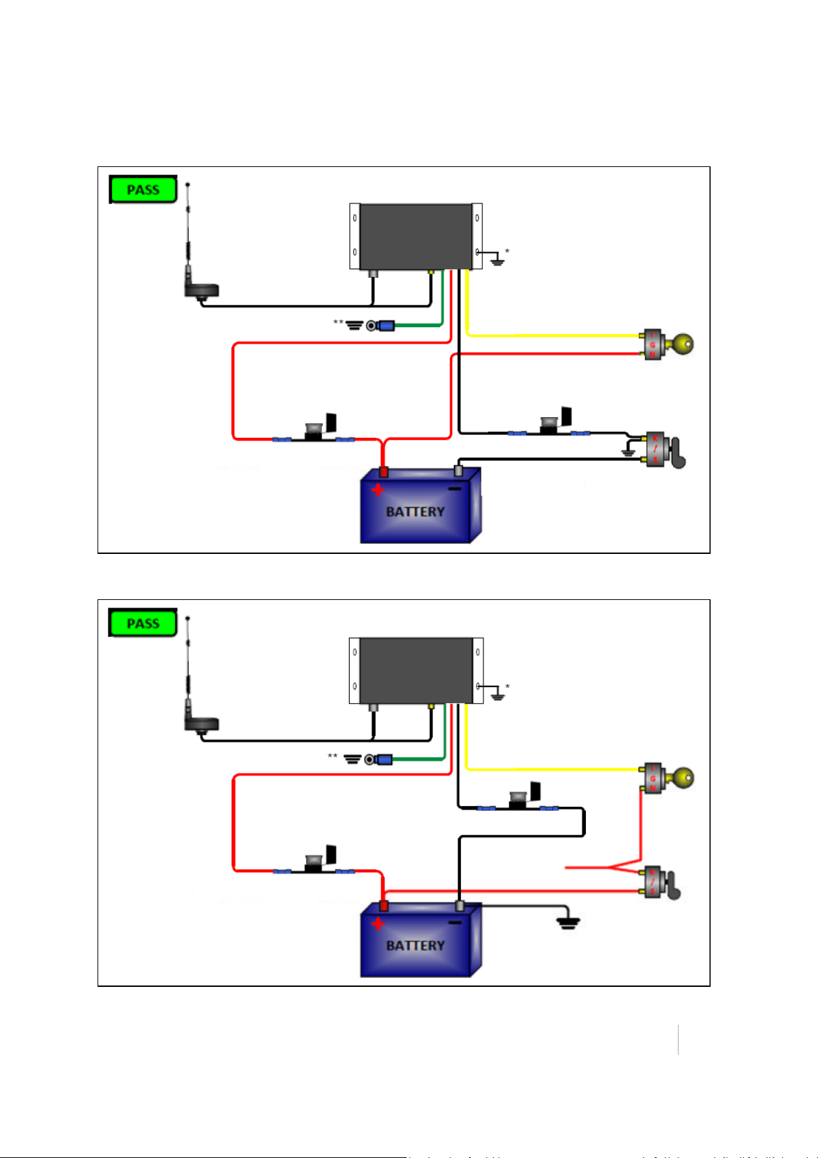
Overall wiring configurations
SNM940
Preferred Chassis Grounding
Alternate Chassis Grounding
To maintain full operational capability,
the device must be connected to
constant power supply and chassis ground.
If the antenna is not
isolated, it will lead to
battery drain or unit
damage.
SNM940
Preferred Chassis Grounding
Alternate Chassis Grounding
To ve h ic l e
constant power
To maintain full operational capability,
the device must be connected to
constant power supply and chassis ground.
If the antenna is not
isolated, it will lead to
battery drain or unit
damage.
Correct wiring for a negative master disconnect
Safety Information
Correct wiring for a positive master disconnect
SNM940 CONNECTED SITE GATEWAY INSTALLATION GUIDE
7
Page 8

CHAPTER
1
Introduction 1
Welcome to the SNM940 Installation Guide. This document describes how to install and verify initial
operation of SNM940.
It is necessary, even for an experienced installer, to review this entire manual in order to become
familiar with the special features that differentiate the SNM940 from any other telematics device. If
you are not familiar with GPS or vehicle telematics, visit the Trimble website (www.trimble.com) for
an interactive look at Trimble and these technologies.
About the SNM940 device
The Trimble SNM940 device comes in two models. The SNM940G supports GSM cellular
communications. The SNM940C supports CDMA cellular communications only through Verizon
Wireless. Both variants offer GPS positioning, cellular communications, wireless LAN
communications, Ignition sense, Engine On sense, three digital inputs, one analog input, and wired
communications using CANbus, RS-232, and Ethernet.
The Trimble SNM940 devices are designed to operate reliably in very harsh installation environments
including all types of heavy construction equipment. These devices can be installed in-cab or out-ofcab. If the host asset has an electronic control module (ECM) installed somewhere, the SNM940 can
be installed in that same location.
Related information
Sources of related information include the following:
• Support Notes – Product support notes describe new features of the product, information not
included in the installation guide, and information on machine model-specific installation. They
are available from Trimble Support (see below) and the Trimble Heavy Civil Construction Sales
team. Support notes are updated as firmware updates are released.
• Trimble training courses – Consider a training course to help you use your GPS telematics system
to its fullest potential. For more information, go to the Trimble website at
www.trimble.com/training.html.
Technical support
If you have a problem and cannot find the information that you need in the product documentation,
contact your local dealer. Else, go to the Support area of the Trimble website
(
www.trimble.com/support.shtml). Select the product you need information on. Product updates,
documentation, and any support issues are available for download.
If you need to contact Trimble technical support, complete the online inquiry form at
(
www.trimble.com/support_form.asp).
SNM940 CONNECTED SITE GATEWAY INSTALLATION GUIDE
8
Page 9

CHAPTER
2
Overview 2
In this chapter:
Exterior description
Electrical harness connector
Antenna connectors
Mounting provisions
Use of digital and analog switches
Electrical harness
This chapter introduces the Trimble SNM940
Connected Site® Gateway. These units make it
easy to receive status information from all types
of construction assets, to effectively manage
them, and to link assets to back office
applications.
The SNM940 device is ideal for the following
applications:
• Heavy earthmoving equipment, such as track
type tractors, scrapers, and motor graders
• On/Off road equipment such as dump trucks,
aggregate haulers, and service trucks
• Portable assets with engines such as
generators, compressors, and pumps
SNM940 CONNECTED SITE GATEWAY INSTALLATION GUIDE
9
Page 10
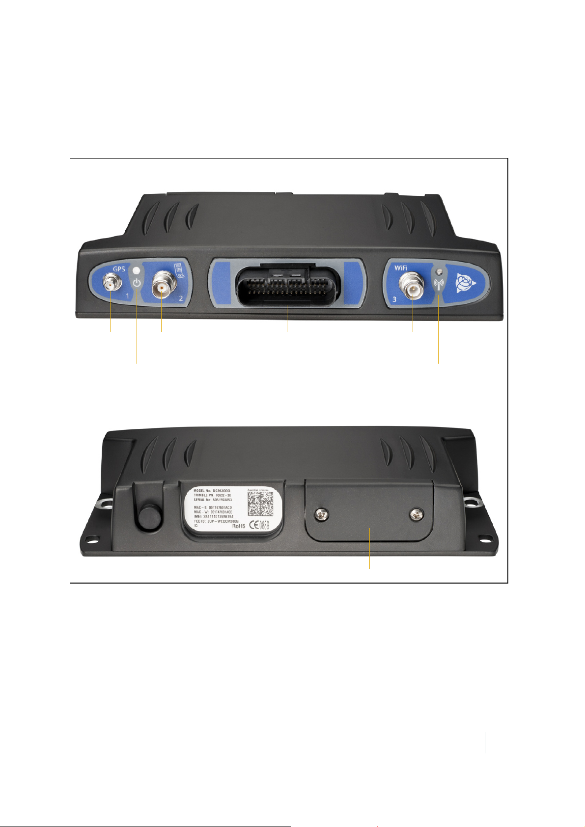
2 – Overview
GPS antenna
Power and GPS
Cellular antenna Electrical harness WLAN antenna
WLAN indicator
FRONT
SIM card access door
BACK
connector
activity indicator
connector connector connector
Exterior description
The Trimble SNM940 device is a rugged telematics and data communications appliance. The device
enclosure is made of heavy duty aluminum. The front of the device contains the electrical harness
connector (see
mounting through-holes (see page 13).
page 14) and antenna ports (see page 11). The bottom of the device includes the four
Figure 2.1 SNM940 exterior
SNM940 CONNECTED SITE GATEWAY INSTALLATION GUIDE
10
Page 11

2 – Overview
Electrical harness connector
The electrical harness connector is a 34-pin weatherproof electrical connector with a mechanical
locking system. For a description of the connector signals and wiring harness configuration, see
Chapter 7, SNM940 Wiring Harness.
Some machine installations may use a specialized wiring harness depending on the telematics
features available on that particular machine. Trimble recommends that you use only harnesses
provided by Trimble or by your machine’s original equipment manufacturer.
For more information, see Chapter 4, Installation.
Note – If adding additional conductors to a factory harness, the conductors must be at least 18 AWG.
Larger conductors are acceptable.
Antenna connectors
The SNM940 device has connectors for three types of external antennas:
• GPS antenna connector – This connector is a SMA jack.
• Cellular modem connector – This connector is a TNC jack.
• Wireless Local Area Network (WLAN or Wi-Fi) antenna connector – This connector is a reverse
polarity TNC jack.
The Trimble-supplied Wi-Fi antenna is a stand-alone component. The Trimble-supplied GPS and
cellular antennas are combined in a single housing.
these connectors.
For more information, see Chapter 4, Installation.
CAUTION – All antennas must be isolated from the chassis ground, or you may run down the
C
machine battery or cause damage to the SNM940.
Figure 2.1 on page 10 shows the locations of
SNM940 CONNECTED SITE GATEWAY INSTALLATION GUIDE
11
Page 12
2 – Overview
SMA type GPS
antenna
TNC type cellular
antenna connector
Antenna
connector
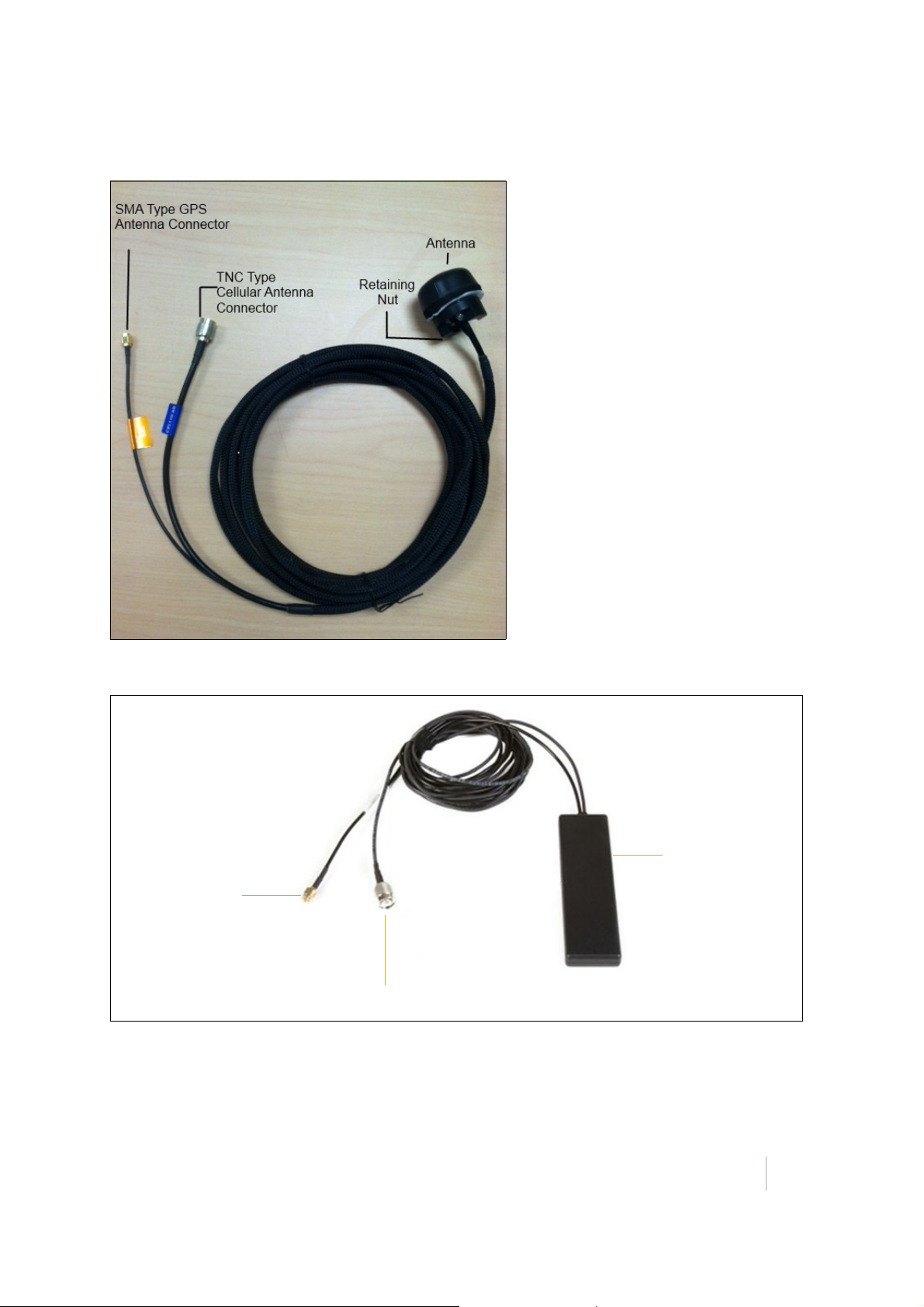
The device requires a combination of GPS/cellular antenna for all installations. There are two major
versions of this antenna; a bulkhead mount and an adhesive mount. The bulkhead mount
(P/N
84398) is the recommended antenna.
Figure 2.2 Bulkhead mount combination GPS/cellular antenna (P/N 84398)
Figure 2.3 Adhesive mount combination GPS/cellular antenna (P/N 82892-30)
SNM940 CONNECTED SITE GATEWAY INSTALLATION GUIDE
12
Page 13
2 – Overview
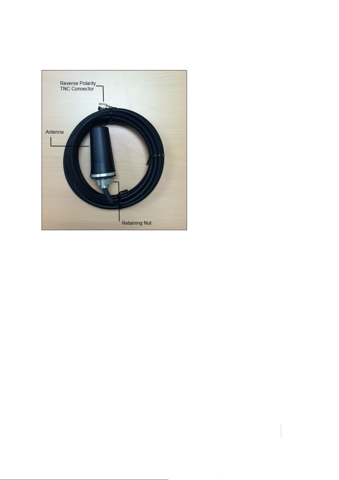
If you require WLAN connectivity, use the Wi-Fi antenna. There is only one model of Wi-Fi antenna
available and it is a bulkhead mount unit.
and an antenna mounting bracket (P/N 84262-10).
A GCS base kit includes a cell/GPS antenna, Wi-Fi antenna,
Figure 2.4 Bulkhead mount Wi-Fi antenna (P/N 84262-10)
Note – Antennas and mounting bracket must be isolated from the machine chassis when installed.
Mounting provisions
The device has four through-hole mounting points, which are located at the four outside corners of
the bottom face. You must use the correct mounting hardware to install these devices. The device is
generally intended to be rigidly mounted to the asset that is being monitored. In the case of
installations where extreme vibration may be encountered, such as directly on the chassis of a
tracked machine, you should use a mechanical shock isolation system. The mounting slots allow the
use of hardware up to 6
For more information, see Chapter 4, Installation.
mm (¼") diameter.
SNM940 CONNECTED SITE GATEWAY INSTALLATION GUIDE
13
Page 14
2 – Overview
Ground
Machine
A switch or connection that is open
A switch or connection that is open
Positive of battery
Machine
OV to battery
Machine
Use of digital and analog switches
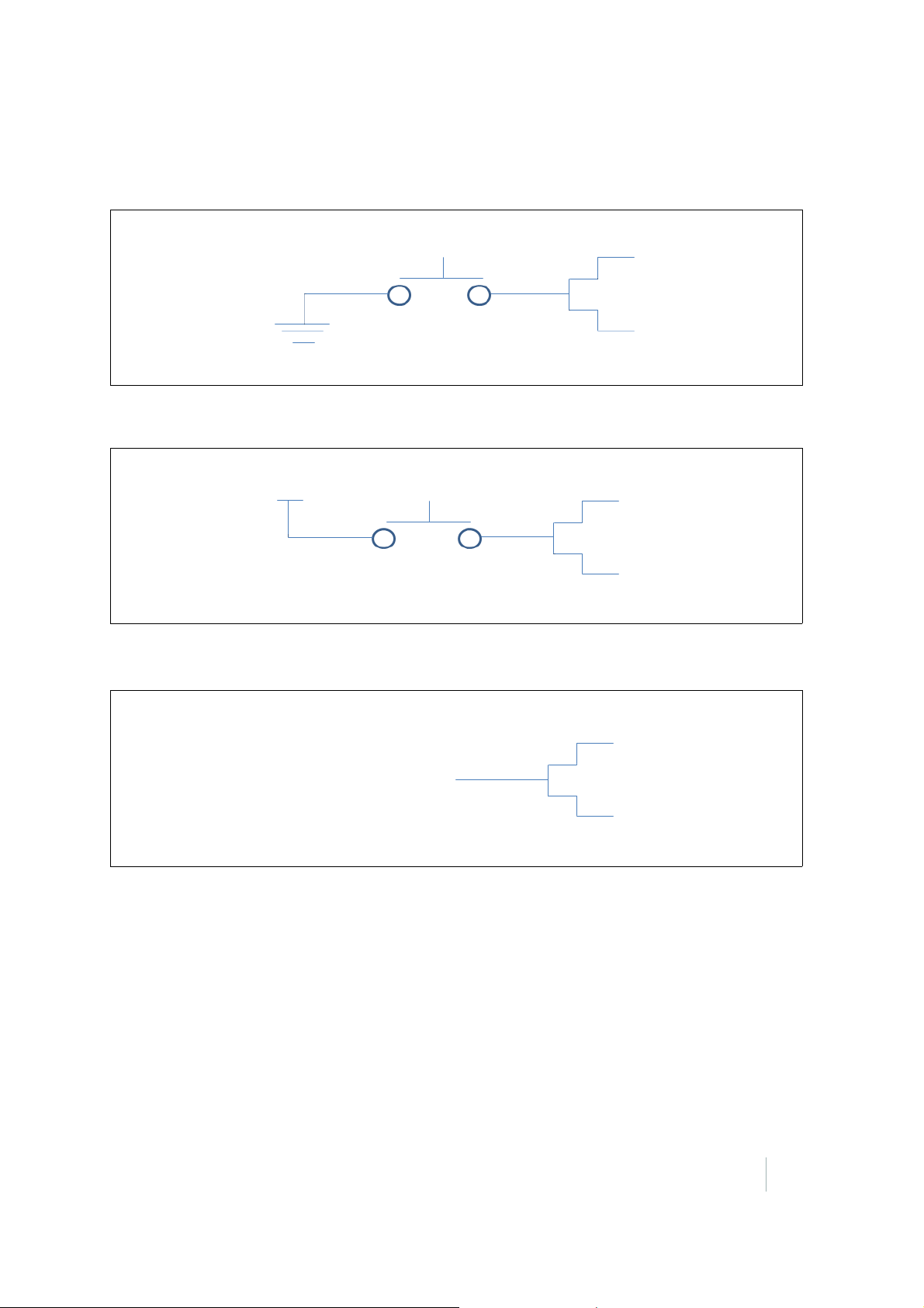
The SNM940 has the digital and analog inputs described above. There are three types of inputs as
shown in the following figures.
Figure 2.5 Digital switches 1 and 2 – Switch to Ground
Figure 2.6 Digital switch 3 – Switch to Battery
Figure 2.7 Analog switch – To positive battery
Electrical harness
The standard electrical harness for the device is Trimble P/N 82892-20.
For details, see Chapter 7, SNM940 Wiring Harness.
SNM940 CONNECTED SITE GATEWAY INSTALLATION GUIDE
14
Page 15

CHAPTER
3
Recommended Tools and Supplies 3
In this chapter:
To ol s
Supplies
Tools
• Wire cutters
• Wire strippers
• Mechanic’s socket set
• Mechanic’s open-end wrench set
• Assorted screw drivers
• Digital multimeter
Every SNM940 installation will vary due to
unique features of the asset being equipped.
The tools and supplies listed below are the
absolute minimum required to complete an
SNM940 installation. A complete mechanic’s
field tool kit is preferred.
Note – Holes will most likely need to be drilled
into the machine for installation purposes.
Ensure that the area drilled will not void
contract or warranty on machine while not
compromising the safety of the operator.
• Crimp tool for insulated barrel type connectors
• Heat source – to shrink tubing
• Drill
• Assorted metal drill bits
SNM940 CONNECTED SITE GATEWAY INSTALLATION GUIDE
15
Page 16

3 – Recommended Tools and Supplies
Supplies
• Soldering supplies (soldering iron, rosin core silver bearing, etc.)
• Solder-less 18-22 AWG barrel type butt connectors
• Solder-less #10-5/16" 18-22 AWG ring terminals
• (4) ¼" or 6 mm fasteners – either nuts and bolts with suitable washers (stainless steel is preferred)
or self-tapping screws
• Tie w raps
• Electrical tape
• Heat shrink tubing in assorted sizes
• 18-gauge wire in multiple colors
• In-line fuse holders
• 5 A fuses
• Cable sheathing such as split loom
Optional additional supplies may include SNM940 mounting brackets, antenna mounting brackets,
and shock mounts.
SNM940 CONNECTED SITE GATEWAY INSTALLATION GUIDE
16
Page 17

CHAPTER
4
Installation 4
In this chapter:
General installation approach
Step 1: Determine the mounting location of
the SNM940 device
Step 2: Plan the route of the electrical
harness
Step 3: Install the fuses
Step 4: Make the electrical connections
Step 5: Determine the location of the
antenna
Step 6: Secure the SNM940 device
Step 7: Complete the device connections
This chapter describes the general procedure to
install an SNM940 device and its necessary
peripheral devices. Trimble assumes you have a
basic knowledge of mechanical and electrical
technical operations.
For a list of recommended tools and supplies for
installation, see
and Supplies.
Note – Before installing any telematics device,
note its serial number for later reference.
Chapter 3, Recommended Tools
General installation approach
In general, the installation is a simple process, however, failure to follow correct installation
guidelines will result in a non-functional or dysfunctional unit. Before starting the installation
process, consider the following guidelines:
• Installation length of components and length of connection wires to main unit. Keep in mind that
it is easier to extend the length of wires from asset terminals rather than change the location of
the antennas or control box.
• Ensure that you are prepared with various installation tools as each installation can be unique to
the machine that it is installed on.
• Ensure that you keep the Quick Installation Guide readily available during the install process; this
guide is shipped with every unit.
The installation can be easily performed by doing the following tasks:
1. Determine the mounting location for the SNM940 device (see page 18).
2. Plan the route of the electrical harness (see page 19).
3. Install the fuses (see page 19).
4. Make the electrical connections (see page 19).
SNM940 CONNECTED SITE GATEWAY INSTALLATION GUIDE
17
Page 18

4 – Installation
5. Determine the mounting location for the antenna (see page 20).
6. Secure the SNM940 device (see page 21).
7. Complete the device connections (see page 21).
Further installation notes
• The SNM940 is designed for use on construction equipment. Attaching to the vehicle chassis or
body is standard procedure and will work well. If possible, avoid attaching the device to a
subcomponent that is prone to extreme shock or vibration, such as the engine block, or
suspension components. On a tracked machine, isolation mounts (P/N 84264-20) may be required
if mounting directly to the chassis.
• Ensure that the chosen mounting location of the SNM940 is in a practical location. If installing for
a specific customer, confirm with the customer that the chosen location is acceptable. For
example, installation in the lunch box compartment may not be an acceptable location.
• Electrical Interference – The SNM940 device operates well in electrically noisy environments, but
installation best practices include avoiding close proximity to alternators, generators, electric
motors, DC to AC converters, switching power supplies, and arc welding equipment. If electrical
interference is suspected, enclose the SNM940 device wiring harness in a grounded shield wrap
or grounded conduit.
• The SNM940 can be connected to the assets CANbus to provide valuable status information made
available through Trimble Cloud software applications. The SNM940 can capture and forward
publicly available data from the CAN, but due to the variety of proprietary messaging and lack of
a clean CANbus standard for machines this advance installation is not covered directly in this
document. Please contact customer support before doing a CANbus installation, as Trimble are
working to constantly improve this functionality and ease of install.
Step 1: Determine the mounting location of the SNM940 device
The SNM940 can be installed in various locations; however the recommended location is in the cab
to allow for:
• ease of access
• increased security
• a minimal distance from the antennas and control box to the main unit.
A mounting surface on the chassis of the machine is preferred to provide a chassis connection to the
SNM940 enclosure.
The SNM940 mounting plate is designed to be fixed in an area with the dimensions of 185 mm x
mm (7.28 in x 9.05 in), to allow adequate space for attachment of the electrical harness, as well
230
as the coaxial antenna connections.
Be sure to avoid mounting the unit in an area with excessive exposure to moisture, dirt, direct heat,
sunlight and chemicals, while still allowing for accessibility, as well as good air flow.
SNM940 CONNECTED SITE GATEWAY INSTALLATION GUIDE
18
Page 19

4 – Installation
Step 2: Plan the route of the electrical harness
Keep in mind the following factors:
• The 34-pin connector on the electrical harness must reach and attach to the SNM940 device. Do
not plug the connector into the SNM940 during this step.
• For use with GCS/AccuGrade systems ensure that the brown connector on the SNM940 harness
can easily reach the corresponding brown connector on the GCS/AccuGrade harness. If there is no
brown connector on the GCS/AccuGrade harness, refer to the SNM940 Ordering Guide (this can
be found online in the Trimble Store help files).
• Locate the chassis conductors that will be attached to the trailing wires of the electrical harness.
• Find a wiring route to reach each of the chassis conductors discussed in Step 4: Make the
electrical connections, page 19. Aim to find an area in which you will easily be able to secure the
wiring once installed.
• Measure out and cut any additional wiring that may be needed to connect the tailing end of the
harness to the machine conductors.
• Wrap as much of the harness and individual conductors as possible in an abrasion-resistant
sheath to reduce the chances of damage. This sheath may be as simple as split loom or as
complex as rigid conduit depending on available materials and the service duty expected on the
particular machine. Make sure that it is possible to mechanically secure all conductors frequently
along their routes.
Step 3: Install the fuses
Plan the location of all inline fuses. These will have to be easily accessible for future maintenance.
The Wiring Harness kit (P/N 82890-20) includes a fuse holder intended to be installed at the Battery
Negative connection. It is standard practice to install a second fuse on the Battery Positive lead at the
positive terminal of the battery, especially if that signal conductor is long and embedded in the asset.
Although not necessary, it is standard practice to install fuses at every connection.
Step 4: Make the electrical connections
The following five connections are crucial connections between the tailing end of the electrical
harness and machine terminals:
• Key Switch Input (Yellow)
• Positive Battery Terminal (Red)
• Negative Battery Terminal (Black)
• Chassis Ground (Green)
• R-Terminal Input (White)
Fuses must be placed at each connection.
SNM940 CONNECTED SITE GATEWAY INSTALLATION GUIDE
19
Page 20

4 – Installation
Each installation may vary in the number of connections made. For more information, see Chapter 7,
SNM940 Wiring Harness.
1. Solder/splice extension wires to harness where needed, and connect wires to respective
locations.
In some machines, the SNM940 continues to stay powered on when connected behind a master
disconnect. To address this, you can use a relay on the Key Switch wire, which interrupts power
that floats across the chassis causing the SNM940 to act as though the machine was running. To
test if this is occurring on your machine, turn off the master disconnect and confirm that after a
few minutes the SNM940 enters low power mode (no LEDs will be lit).
2. After harness and tailing wires have been connected, secure the harness and wires to solid
surroundings with the zip ties.
Note – The brown, purple, orange and blue wires are digital and analog input wires that are not
crucial to the operation of the SNM940.
Step 5: Determine the location of the antenna
The antenna locations will have a significant effect on the performance quality of the SNM940
device.
• Mount antennas in an area that has a clear 360° view of the sky and is at least 20 cm from all
other transmitting antennas, the operator and any other occupant, while still allowing the
antenna cables to easily reach the SNM940.
• The antennas should not be easily sighted, to reduce the chances of tampering or disablement.
• The antennas should be firmly attached to the asset so that they will not come loose due to
shock, vibration, or thermal cycling.
• The bulkhead mount combination GPS/Cellular antenna may be mounted directly to a horizontal
surface near the top of the asset by drilling a hole of at least 19
surface. You can also use a simple “C” shaped bracket to mount the bulkhead antenna as shown
Figure 2.2 on page 12. The wireless LAN (WLAN) antenna shares these mounting requirements.
in
The WLAN antenna mount must be electrically isolated from the asset’s chassis ground.
CAUTION – The antenna mounts must be electrically isolated from the asset’s chassis ground.
C
Failure to do so, may result in battery drain and potential damage to the SNM940.
• The adhesive mount combination GPS/Cellular antenna can be mounted on the inside of a
window within an asset’s cab. This antenna usually gives adequate performance for asset
management-only installations. If more accurate positioning and large file communications are
needed, Trimble recommends that you use the bulkhead mount antenna.
mm (¾") diameter through the
SNM940 CONNECTED SITE GATEWAY INSTALLATION GUIDE
20
Page 21

4 – Installation
Step 6: Secure the SNM940 device
• Trimble recommends that you use the provided mounting bracket for installation of the SNM940.
If the chosen mounting location is outside of the cab on a tracked vehicle, then the shock plate
must be used. If the isolation mount (P/N 84313-20) is used, a braided wire must be installed to
ground the chassis of the SNM940 to the chassis of the machine through one of the mounting
holes on the shock plate. Please note that the shock mount must be bolted to the machine. In
most cases this means that the holes must be drilled to accommodate for this.
• If the mounting bracket is not to be used, drill a rectangular array of 7 mm (¼”) holes with the
dimensions of 215.4 mm x 60 mm (8.48” x 2.36”).
• Secure the SNM940 to the mounting position using four M16 ¼” bolts, nuts, and washers.
• Firmly tighten the bolts.
Step 7: Complete the device connections
• Attach the WLAN and GPS/cellular antenna connectors to the SNM940.
• For use with GCS900 or AccuGrade systems, plug the brown connector from the SNM940 harness
to the corresponding brown connector on the GCS900 or AccuGrade harness.
• Attach the power harness to the SNM940.
• Turn the machine on and observe to see the flashing LEDs (see LED indicators, page 23).
SNM940 CONNECTED SITE GATEWAY INSTALLATION GUIDE
21
Page 22

CHAPTER
5
Operation Verification 5
In this chapter:
LED indicators
Verifying that the SNM940 device is powered
and operating
Web tool setup and operation
This chapter describes how to verify the basic
operation of a newly-installed SNM940 device.
SNM940 CONNECTED SITE GATEWAY INSTALLATION GUIDE
22
Page 23
LED indicators
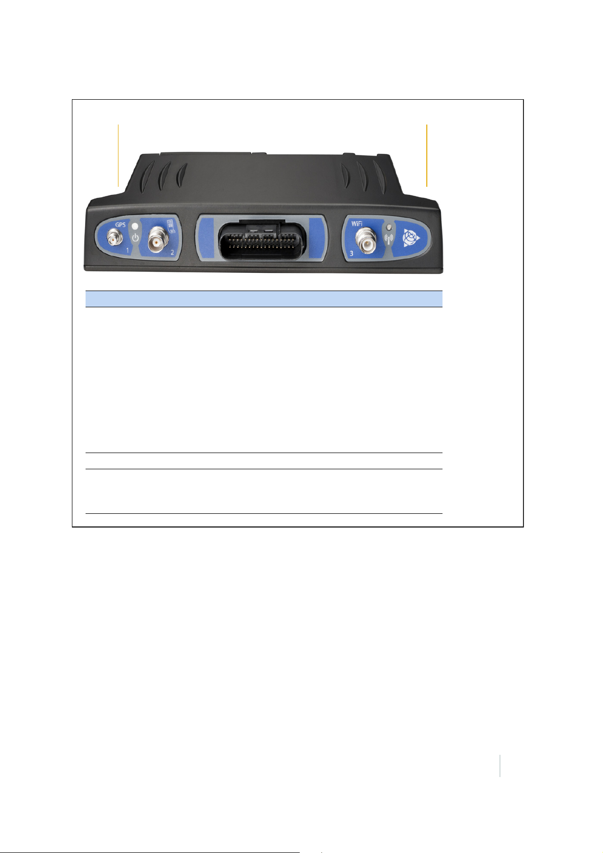
Green LED
Power and GPS
Amber LED
Wireless communications
statusstatus
LED status Green LED Amber LED
Powered and initializing On Solid Off
GPS providing a position Blink N/A
No GPS signal or poor position quality Fast Blink N/A
Cellular data connection N/A On Solid
WLAN data connection N/A Blink
WLAN and cellular connections N/A Slow Blink
Poor or no wireless connection N/A Fast Blink
Low power standby Off Off
Hardware failure On Solid On Solid
Slow blink = 3 seconds on / 3 seconds off
Blink = 1 second on / 1 second off
Fast blink = 200 milliseconds on / 200 milliseconds off
5 – Operation Verification
SNM940 CONNECTED SITE GATEWAY INSTALLATION GUIDE
23
Page 24
5 – Operation Verification
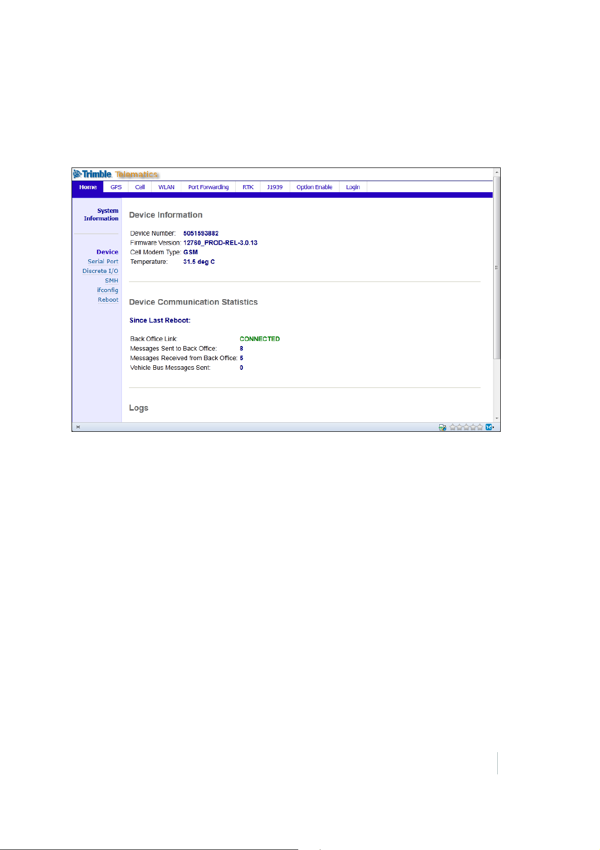
Verifying that the SNM940 device is powered and operating
Along with LED activity, the ability to see the Home page (shown below) indicates that the device is
powered and operating. If this screen does not appear, you may need to send a high signal to the Key
Switch input to initialize the device.
SNM940 CONNECTED SITE GATEWAY INSTALLATION GUIDE
24
Page 25
5 – Operation Verification
Web tool setup and operation
For more advanced web tool usage, refer to the DCM300/SNM940 Web Service Tool User Guide. For
typical installation follow these instructions to enable the described features.
Base setup
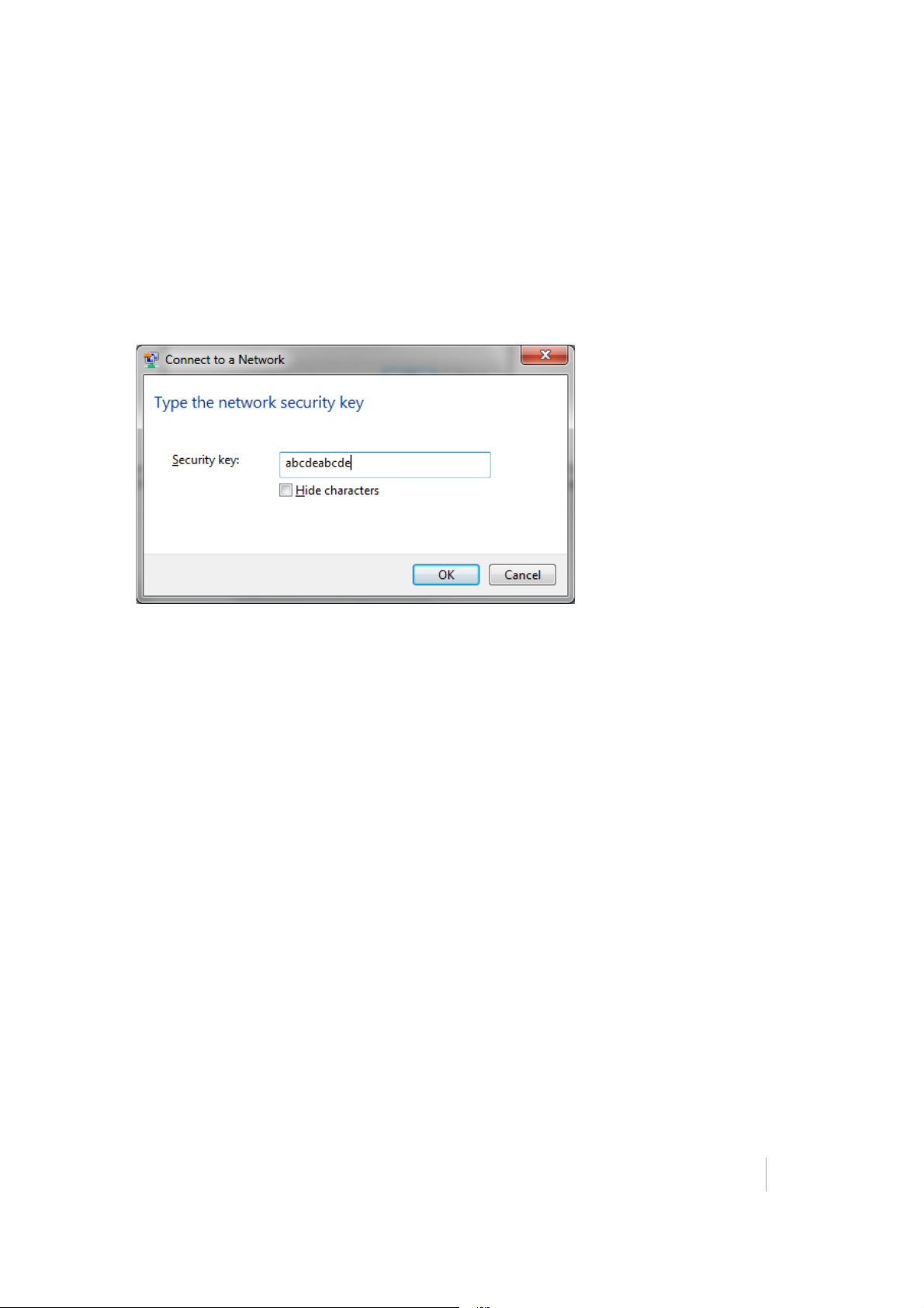
1. When the SNM940 is turned on, it will create a service network on its WLAN radio. Connect to
the Trimble Service (<Serial Number>) network on your computer. Enter the security key to
connect to the network. The security key is abcdeabcde
2. Click OK to connect to the SNM940 WLAN. Allow at less two minutes for the network connection
to be recognized and registered before you access the device.
3. Open an Internet browser and then enter the address 192.168.33.1. The Trimble Telematics
page appears.
For further information regarding the advanced usage of the web service tool please refer to the
DCM300/SNM940 Web Service Tool User Guide.
SNM940 CONNECTED SITE GATEWAY INSTALLATION GUIDE
25
Page 26
5 – Operation Verification
Cellular phone setup
There are two ways to set up the cell service depending on the model of the SNM940 device
purchased.
• Verizon Units: SNM940 Telematic units (P/N 806320-10-HH) ship with an active low data rate
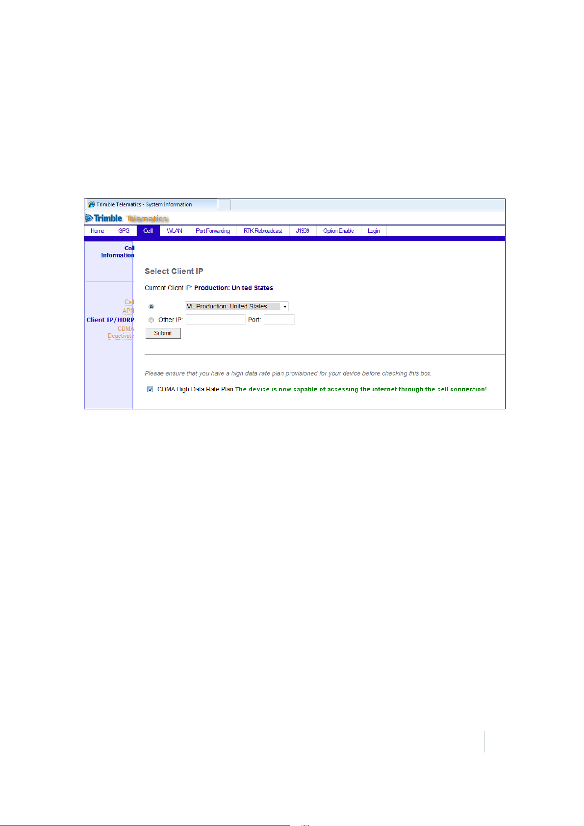
plan. For details on how to update to a high data rate plan, refer to the SNM940 Ordering Guide.
For units with a high data rate plan, you must still enable the connection within the SNM940 Web
Service Tool. In the SNM940 Web Service tool, select the Cell tab, then select Client IP/HDRP.
Ensure that the CDMA High Data Rate Plan check box is selected in the following screen:
SNM940 CONNECTED SITE GATEWAY INSTALLATION GUIDE
26
Page 27
5 – Operation Verification
• GSM Units: To activate cell coverage for an SNM940G unit, a high data rate SIM card must be
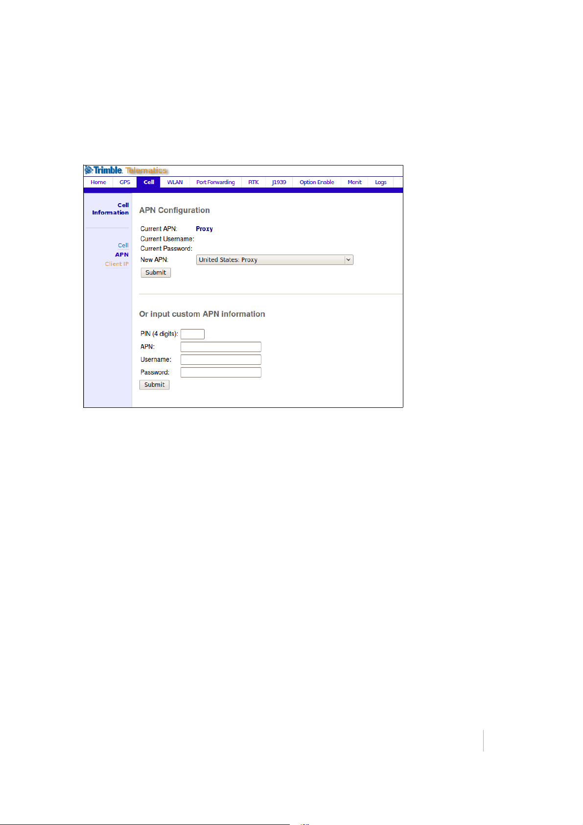
purchased through your local cellular provider. SNM940 Connected Site units (P/N 87940-30) are
shipped with an inactive SIM that must be replaced with an active SIM during installation. Ensure
that the SIM card is active at the time of purchase. If the SIM comes with a corresponding pin
number, enter the pin into the Web Service Tool or CB4x0 before swapping the SIM. After the pin
is entered, the Trimble provided SIM can be replaced with the newly purchased one. For more
information on replacing the SIM, see
Chapter 8, Installing the SIM Card.
SNM940 CONNECTED SITE GATEWAY INSTALLATION GUIDE
27
Page 28
5 – Operation Verification
Verifying GPS positioning
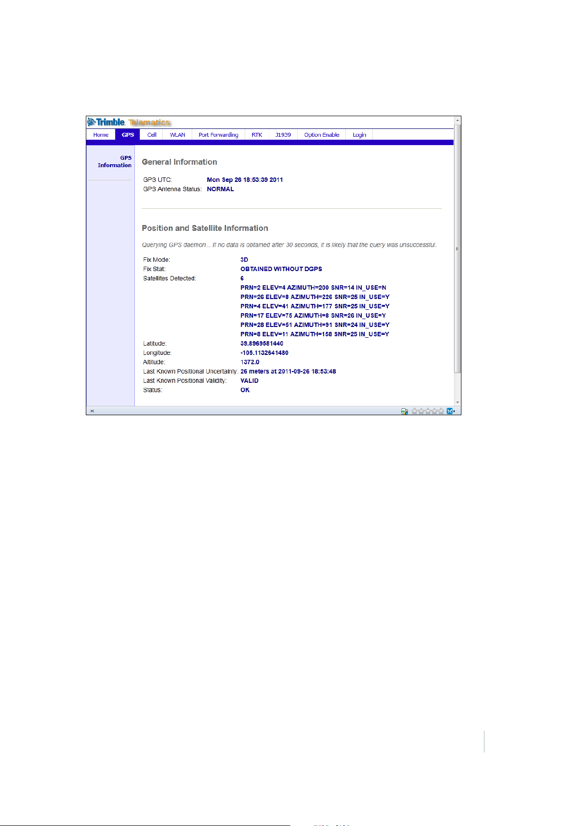
1. In the SNM940 Web Tool page, select the GPS tab. The following page appears:
2. Check that the GPS Antenna Status field shows “NORMAL”, which indicates that the antenna is
attached and capable of tracking satellites.
3. Check that the value in the Satellites Detected field is 1 or higher, which indicates that the GPS
system is capable of functioning. If the antenna currently has a clear sky view, there should be at
least four satellites in view.
4. Check that values are displayed in the Latitude and Longitude fields and that the Status field
shows
OK, which indicates that the GPS receiver is working correctly.
SNM940 CONNECTED SITE GATEWAY INSTALLATION GUIDE
28
Page 29
5 – Operation Verification
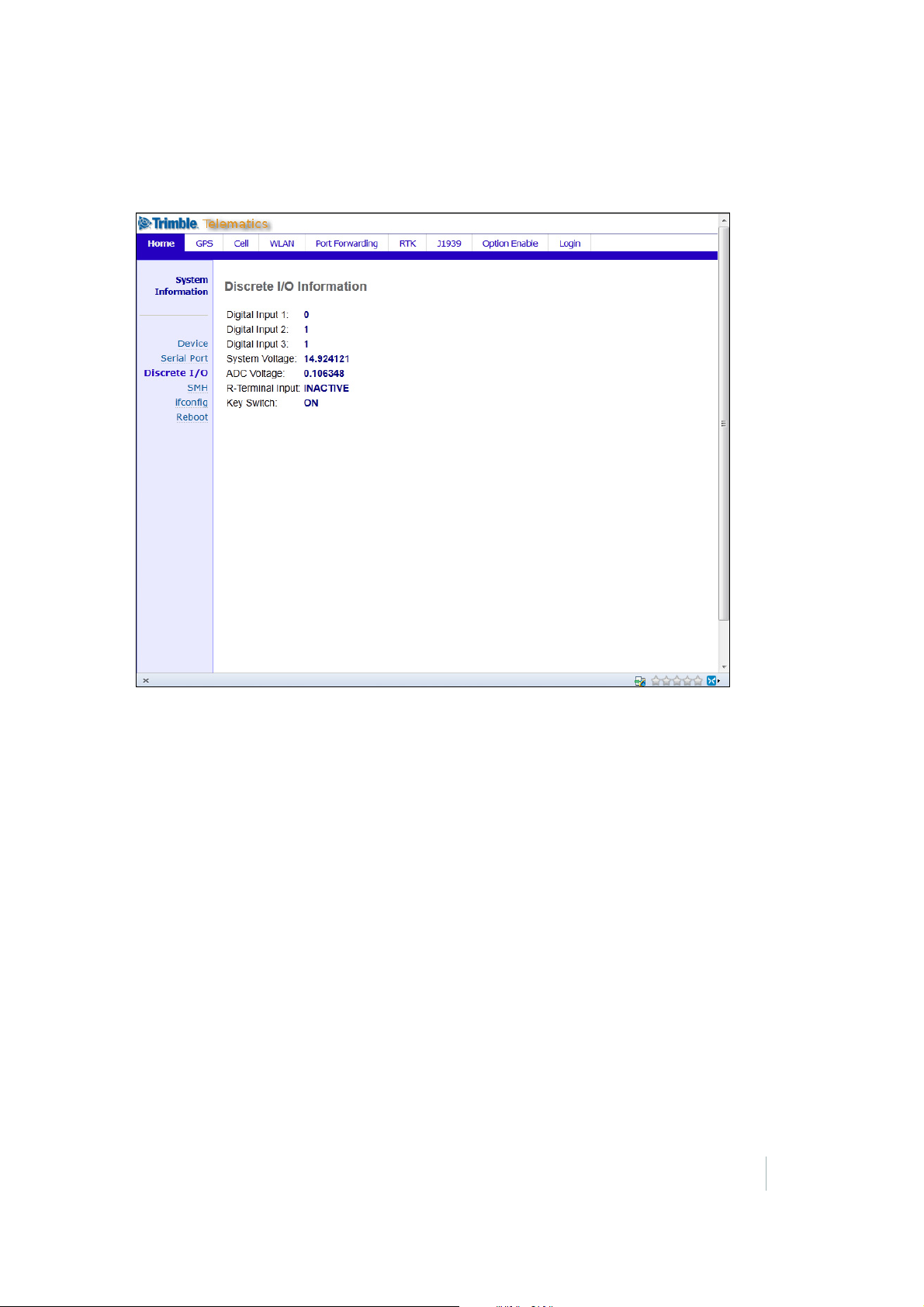
Verifying major inputs
1. Select the Home tab.
2. Select the Discrete I/O menu on the left of the screen. The following page appears:
3. Note the value shown in the Key Switch field. Turn the key switch on the machine to the Off
position.
4. Click Refresh in the web browser to update the page. The Key Switch field indicates OFF when the
page refreshes.
5. Turn the key switch on the machine to the On position. Click Refresh in the browser to update the
page. The Key Switch field changes to ON when the page refreshes to indicate that the device is
correctly sensing the key switch state.
Verifying engine run state sensing
1. Remain in the Discrete I/O page and start the asset’s engine.
2. Click Refresh in the browser. The R-Terminal Input field changes to show Active when the page
refreshes.
3. Turn off the engine and refresh the web page. The R-terminal Input field changes to show
INACTIVE when the page refreshes to indicate that the device is correctly indicating the sensing
of the Engine Run state.
SNM940 CONNECTED SITE GATEWAY INSTALLATION GUIDE
29
Page 30
5 – Operation Verification
In some machines, the SNM940 continues to stay powered on when connected behind a master
disconnect. To address this, you can use a relay on the Key Switch wire, which interrupts power
that floats across the chassis causing the SNM940 to act as though the machine was running. To
test if this is occurring on your machine, turn off the master disconnect and confirm that after a
few minutes the SNM940 enters low power mode (no LEDs will be lit).
Verifying that the SNM940 device is communicating with the VisionLink software
With the Key Switch on, select the Home tab. The screen shows Connected in large green letters to
indicate it is successfully communicating with the VisionLink™ software. Any value of 1 or higher in
the Messages Sent to Back Office and Messages Received from Back Office fields are an additional
positive indicator of two-way communications with the VisionLink software. See the example on
page 24.
Note – If you are testing the SNM940 device, the VisionLink server must be available for the
Connected indicator to appear.
Enabling SNM940 device options
Device options including the Connected Site Link functionality can be enabled in the device by
entering an option code in the Web Service tool. This section describes how to enter an option code
and verify the availability of additional device capabilities.
When a device upgrade is ordered from Trimble, a device option code is provided either directly on
the electronic store or by email. One common code enables the Connected Site Link functionality.
The following example shows how to enter a Connected Site Link option code and how the Web
Service tool display updates to reflect that the option is successfully enabled.
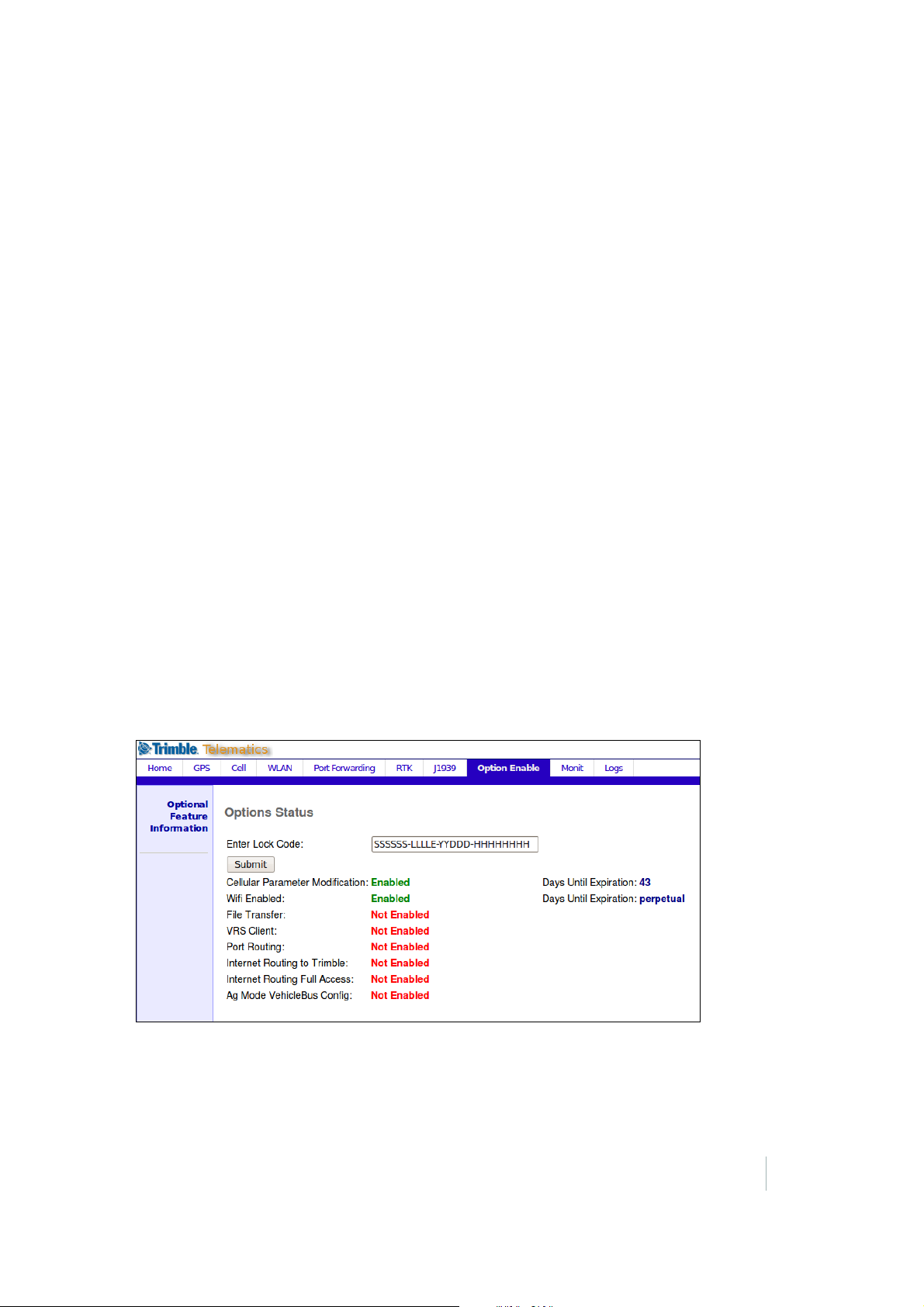
1. Select the Option Enable tab. The following page appears:
Note – Internet Routing Full Access must be enabled for GCS/Accugrade.
2. Copy the Trimble-supplied option code and paste it into the Enter Lock Code field and then click
Submit. The optional features will be enabled and the page shows the feature status in green.
SNM940 CONNECTED SITE GATEWAY INSTALLATION GUIDE
30
Page 31
5 – Operation Verification
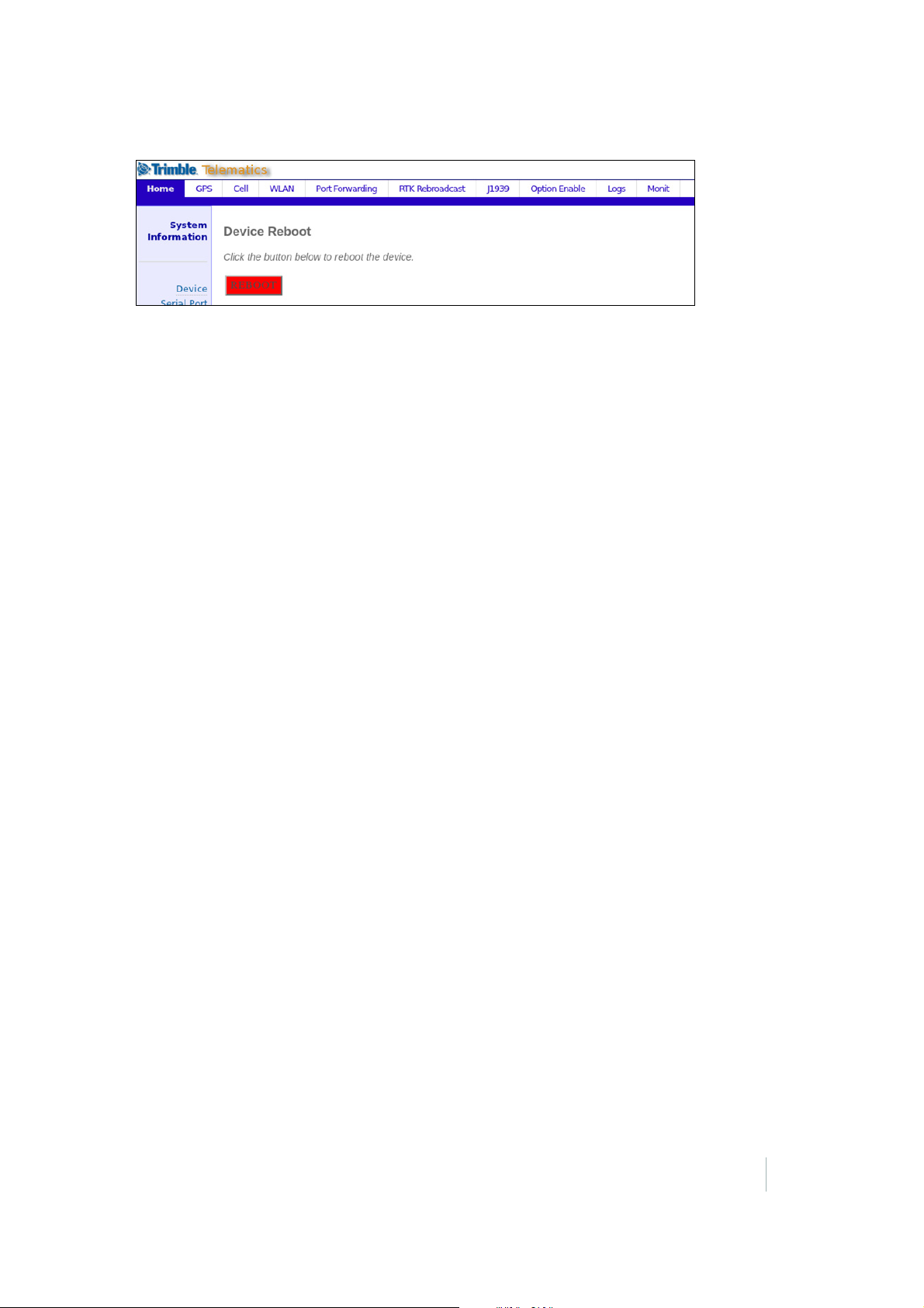
3. After viewing confirmation of the installed option, select the Home tab. Select the Reboot link on
the left side of the screen. Click
Reboot.
4. Allow the device approximately two minutes to restart to save the option settings. Select the
Home tab. When the Home tab refreshes, the restart cycle is complete and the options are
correctly installed. You can then start to use the SNM940 device.
SNM940 CONNECTED SITE GATEWAY INSTALLATION GUIDE
31
Page 32

CHAPTER
6
Locating the R Terminal 6
In this chapter:
Location of the R terminal This chapter describes the location of the
terminal signal on several different alternator
R
designs.
SNM940 CONNECTED SITE GATEWAY INSTALLATION GUIDE
32
Page 33
6 – Locating the R Terminal
Location of the R terminal
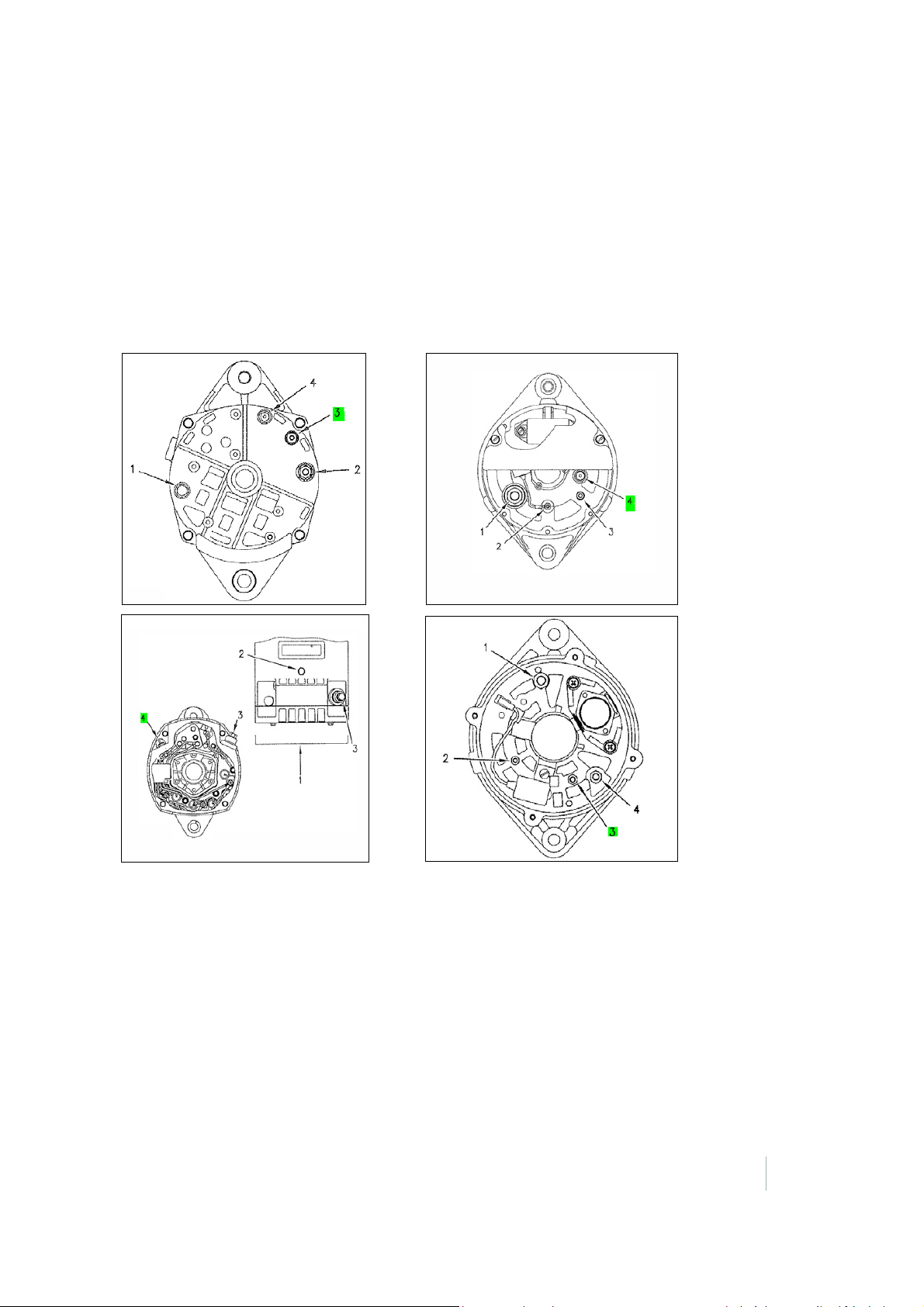
The location of the R terminal differs depending on the alternator used in the machine. If you cannot
locate the alternator’s R terminal, contact a qualified service technician for that machine.
The following are some examples of different alternators used in heavy machines, and the location of
the R terminal.
On machines that do not have an R terminal signal connection or a similar connection that is only
active when the engine is running, connect the R terminal wire directly to the yellow key switch wire.
Both of these inputs can be driven by a key-switched signal source. In this case, engine hours are
accrued when the key switch is on, even if the engine is not running.
SNM940 CONNECTED SITE GATEWAY INSTALLATION GUIDE
33
Page 34
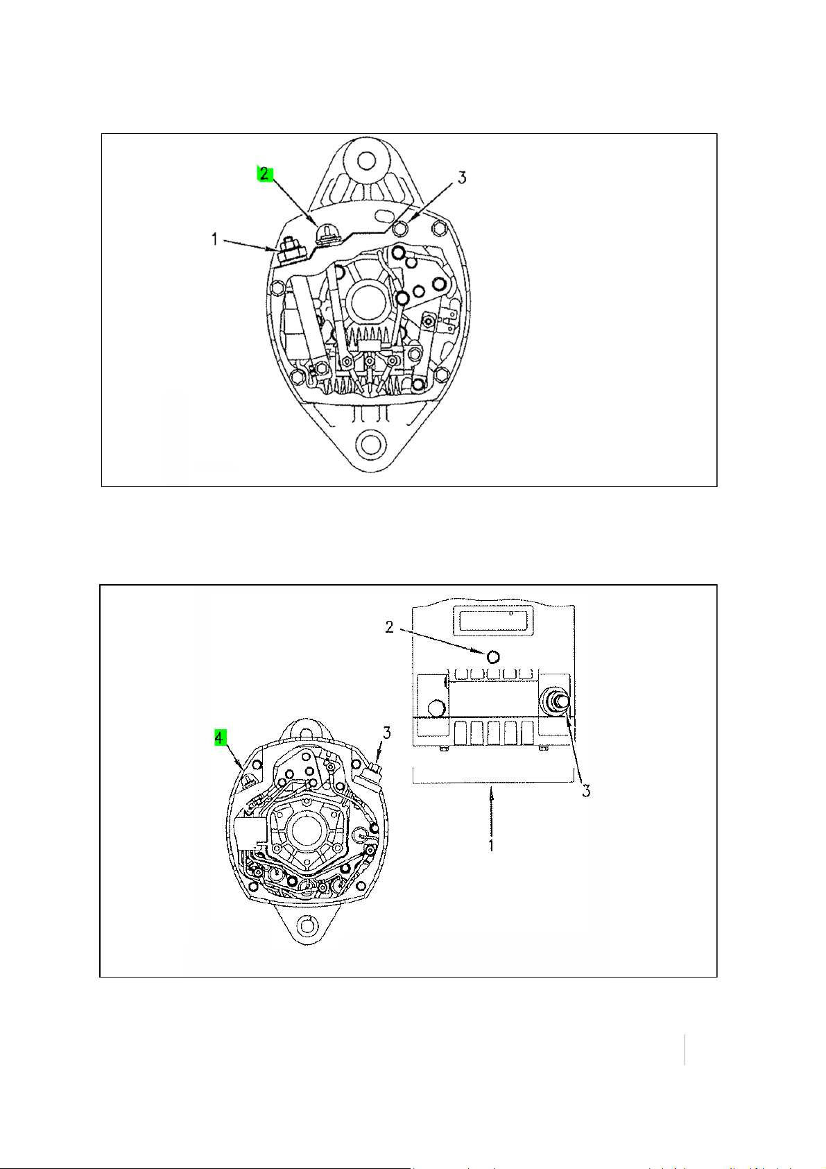
6 – Locating the R Terminal
1 – B+ terminal
2 – terminal
3 – B- terminal
1 – Top view
2 – B- terminal
3 – B+ terminal
4 – R terminal
Delco-Remy 3T-6352, 5N-5692, and 7G-7889 alternators
Delco-Remy 3E-7892, 3E-7578, 3E-7655, and 112-5041 alternators
SNM940 CONNECTED SITE GATEWAY INSTALLATION GUIDE
34
Page 35
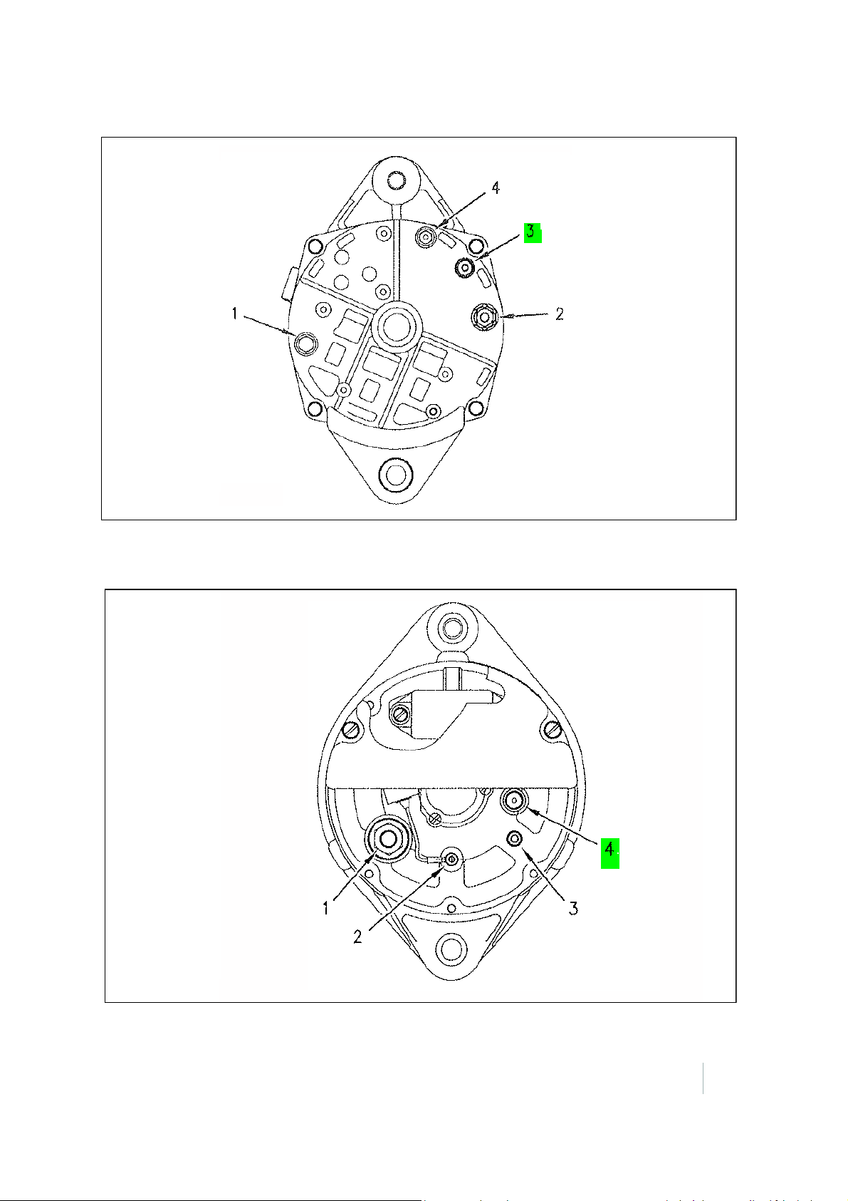
Delco-Remy 155-7434 alternator
1 – B- terminal
2 – B+ terminal
3 – R terminal
4 – Indicator light terminal
1 – B+ terminal
2 – D+ terminal
3 – B- terminal
4 – R terminal
6 – Locating the R Terminal
Bosch 7N-9720, 9G-9538, and 100-5046 alternators
SNM940 CONNECTED SITE GATEWAY INSTALLATION GUIDE
35
Page 36
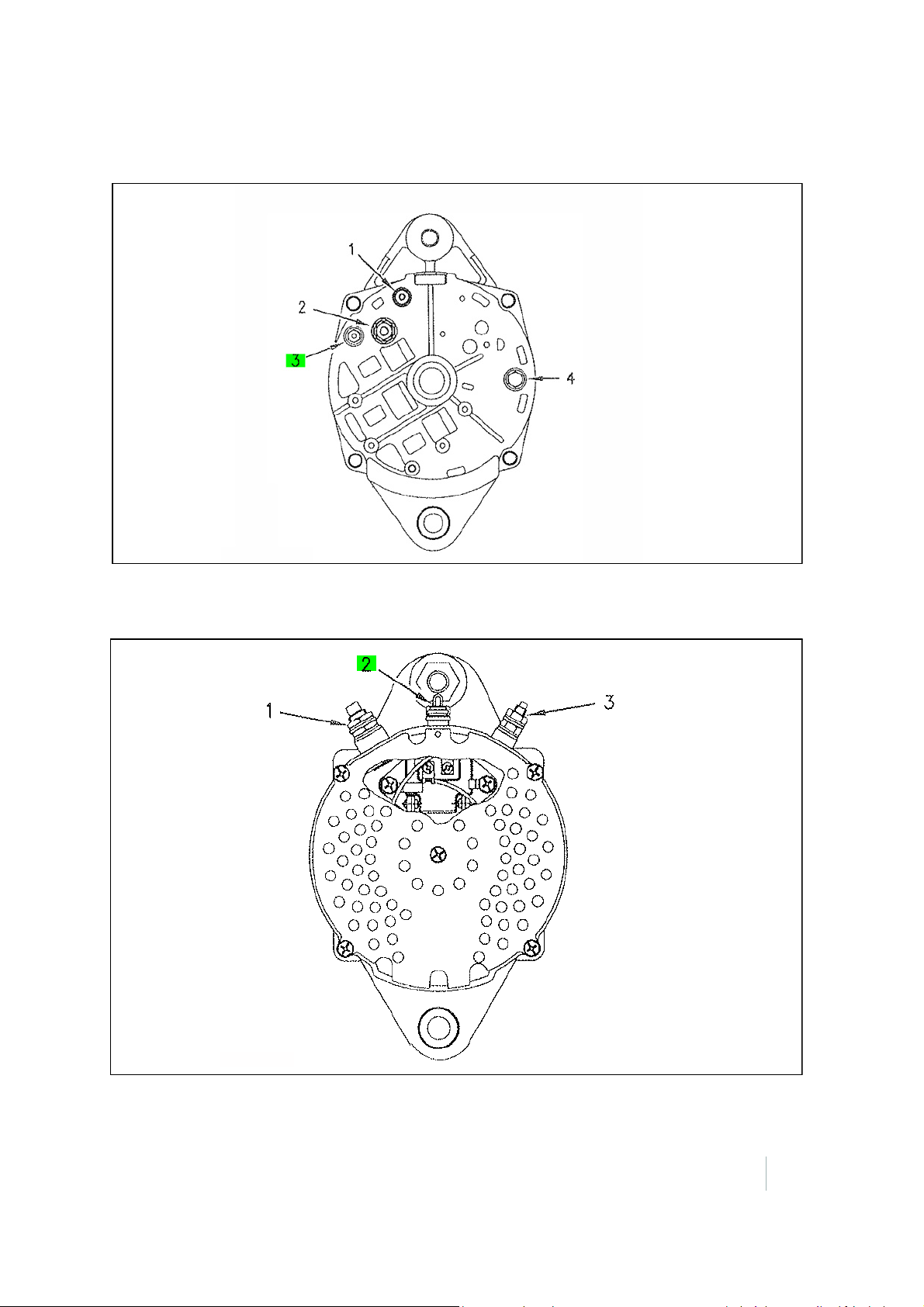
6 – Locating the R Terminal
1 – Optional warning light terminal
2 – B+ terminal
3 – R terminal
4 – B- terminal
1 – B+ terminal
2 – R terminal
3 – B- terminal
Delco-Remy 9X-6796, 107-7977, 117-1379, 121-4134, 1214135, 125-9597, and 132-2156 alternators
Denso 9G-4574, 6T-7223, and 100-5045 alternators
SNM940 CONNECTED SITE GATEWAY INSTALLATION GUIDE
36
Page 37
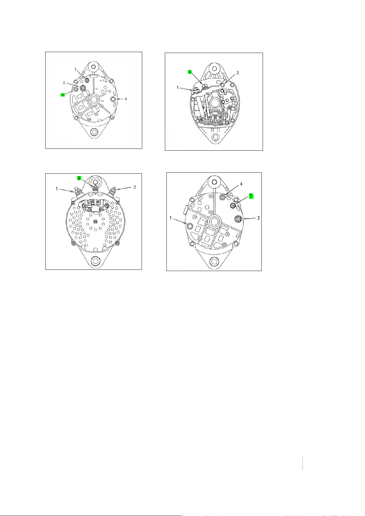
6 – Locating the R Terminal
In situations in which an alternator pictured above is not applicable, R terminal can be determined
by using a voltage meter. Clip the Alternator Wires (be careful to do this far enough from the
alternator to repair the wire and make the final connection).
The alternators typically have 3 outputs. To determine the R-terminal look for a wire that shows all of
the following behavior:
• No voltage when the machine is off.
• No voltage when the machine Key switch is on, but the engine is not running.
• DC voltage equivalent to battery or pulse signal of 50 Hz or greater when the machine engine is
running. For pulse signals it may show half of battery voltage, so confirm that you have your
frequency adjusted to account for pulse signals.
This connection should be made in parallel to the output. After connecting the white R terminal wire
to the identified R terminal, run the machine for a minimum of 10 minutes to confirm in the web
service tool that the correct run time is accruing.
In some cases the alternator may be sending a pulse signal, or be outside the correct supported
frequency to register. If service hours are not reporting correctly, it is possible to connect to the
positive output of the oil pressure gauge, but this should only be done if the R
terminal is not a
workable solution.
SNM940 CONNECTED SITE GATEWAY INSTALLATION GUIDE
37
Page 38

CHAPTER
7
SNM940 Wiring Harness 7
In this chapter:
SNM940 wiring harness
Trailing wires configuration
Brown connector pin outs
Recommended DC electrical specifications
This chapter describes the SNM940 wiring
harness and electrical connections in detail.
SNM940 CONNECTED SITE GATEWAY INSTALLATION GUIDE
38
Page 39
7 – SNM940 Wiring Harness
Tra il ing
wires
Battery and
input fuse
holder
P1 - 34-pin connector
Harness accessories
P5 - Brown connector
P4 - Three
socket
connector
Connect to bulkhead on
the SNM940
Connect t
-1939
(CANbu)
Connect to corresponing
rown connector on
CS or AccuGrade harness
SNM940 wiring harness
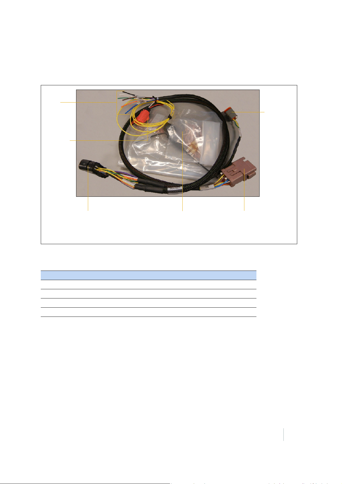
The standalone telematics wiring harness kit (P/N 82892-20) includes accessories to make
installation easier. The following figure shows the kit and the available connections on the wiring
harness. If used with a base kit, the correct harness will be provided.
Tab le 7.1 lists the items in the harness accessories bag.
Table 7.1 Harness accessories
Description Quantity
Fuse holder 1
5 A fuse 2
Ring terminal with heat shrink insulator 4
Butt splice with heat shrink insulator 10
SNM940 CONNECTED SITE GATEWAY INSTALLATION GUIDE
39
Page 40

7 – SNM940 Wiring Harness
Tab le 7.2 describes the conductors in the Wiring Harness kit.
Table 7.2 Conductors
34-pin connector Signal description Wire color Termination
1 Battery - Input Black Trailing Wire
3 Chassis Ground Green Tra i l i n g W ir e
5 Key Switch Input Yellow Trailing W ire
6 Analog Input Purple Trailing Wire
7 Digital Input 1 Brown Trai l ing W i re
9 Ethernet TX- Orange P5 – Brown Connector – Pin 6
10 Ethernet TX+ Yel lo w P5 – Brown Connector – Pin 5
12 RS-232 TX Brown P5 – Brown Connector – Pin 10
13 CAN A Low Green P4 – 3 Socket Connector – Socket B
14 CAN A High Yellow P4 – 3 Socket Connector – Socket A
19 Battery + Input Red Trailing Wire with Fuse Holder
22 Digital Input 3 Orange Tra i l in g W ire
23 R-Terminal Input White Trailing Wire
24 Digital Input 2 Blue Tra i l i n g W ir e
25 Ethernet Shield Silver N/A
26 Ethernet RX- Blue P5 – Brown Connector – Pin 8
27 Ethernet RX+ White P5 – Brown Connector – Pin 7
29 RS-232 RX Red P5 – Brown Connector – Pin 3
32 RS-232 Ground Yel lo w P5 – Brown Connector – Pin 11
Pin numbers not listed above are not connected in the wiring harness. For additional detail on the
nature of the signal connections, see
Tab le 7.3.
Note – All electrical conductors used in the installation of an SNM940 Connected Site Gateway must
be 18 AWG or larger.
SNM940 CONNECTED SITE GATEWAY INSTALLATION GUIDE
40
Page 41
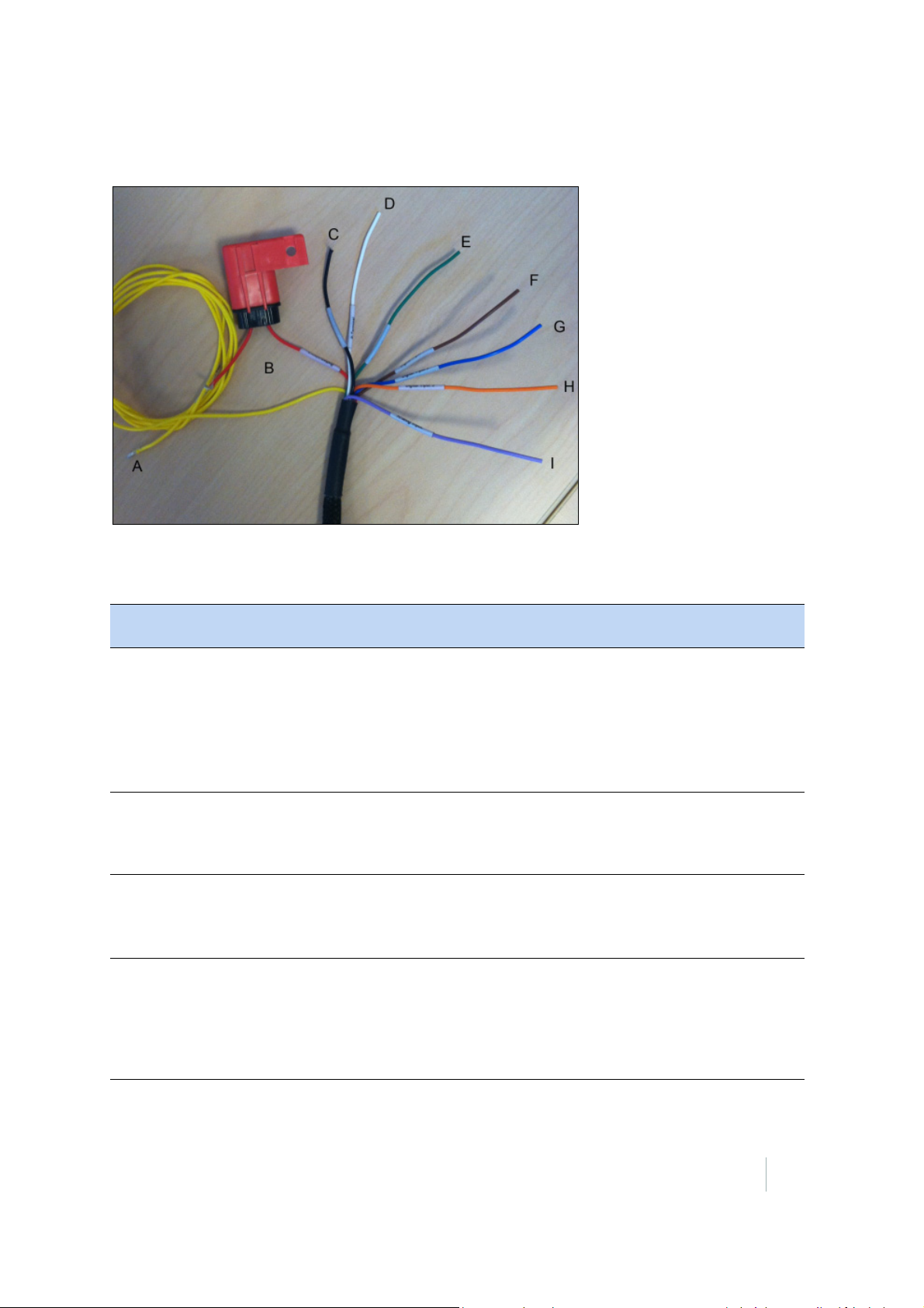
Trailing wires configuration
The following figure shows the trailing wires configuration.
7 – SNM940 Wiring Harness
Tab le 7.3 describes the conductors in the trailing wires of electrical harness:
Table 7.3 Trailing wire conductors
Conductor IDConductor
Pin Number*
A 5 Key Switch
B 19 Battery + Input Red Positive terminal on battery. Terminal with the
C 1 Battery - Input Black Negative terminal on battery. Terminal that connects
D 23 R-Terminal
Signal
description
Input
Input
Wire
color
Yellow An electrical accessory circuit that becomes active
White The relay terminal on the engine’s alternator or a
Connection
when the asset’s key switch is moved to the
“accessory” and “run” positions.
Required to initialize the SNM940 as soon as an
operator activates an asset.
Note – If this connection is not made, the device will
shut off after 10 minutes of run time.
highest voltage in multi-battery configurations.
Required to provide continuous power to the
SNM940.
to chassis ground in multi-battery configurations.
Required to provide continuous power to the
SNM940.
signal such as an oil pressure switch that provides a
signal of 85% of system voltage or greater.
This signal is used to determine runtime hours. If the
R-terminal is not accessible, see
the R Terminal.
Chapter 6, Locating
SNM940 CONNECTED SITE GATEWAY INSTALLATION GUIDE
41
Page 42

Table 7.3 Trailing wire conductors
7 – SNM940 Wiring Harness
Conductor IDConductor
Pin Number*
E 3 Chassis Ground Green Reliable connection to asset’s conductive chassis.
F 7 Digital Input 1 Brown Optional – A sensor that provides a ground signal
G 24 Digital Input 2 Blue Optional – A sensor that provides a ground signal
H 22 Digital Input 3 Orange Optional – A sensor that provides a system voltage
I 6 Analog Input Purple Optional – A sensor with an analog output or an
Signal
description
Wire
color
Connection
Required to detect open negative master disconnect.
Required EMI connection to asset’s conductive
chassis. Failure to make this connection could cause
erratic behavior on the device.
when a monitored situation occurs. If not used
connect to ground or let float. This can be an open
circuit or short circuit to ground, i.e. when the
monitored state occurs, the signal should be ground.
For more information, see Brown connector pin outs,
page 43 or refer to the GCSFlex Installation Guide.
when a monitored situation occurs. If not used
connect to ground or let float. This can be an open
circuit or short circuit to ground, i.e. when the
monitored state occurs the signal should be ground.
signal when a monitored situation occurs. Connect to
system voltage or let float. This will cause the unit to
wake up when the asset is in low power mode.
accessory electrical circuit where voltage monitoring
is required. This sensor must be no greater than
system voltage.
For more information on conductor pin numbers, see Ta bl e 7.2.
SNM940 CONNECTED SITE GATEWAY INSTALLATION GUIDE
42
Page 43
Brown connector pin outs
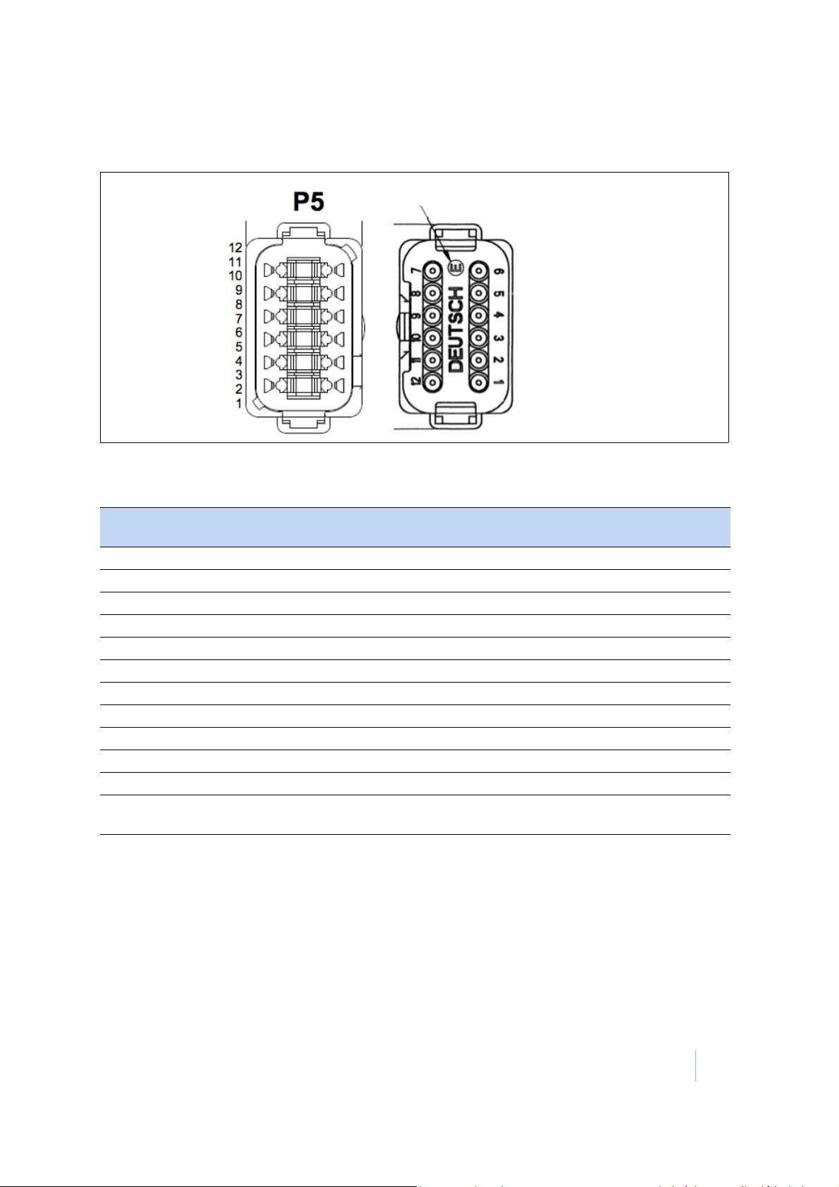
- E - Symbol designates reduced wire seal
The following figure shows the configuration of the brown connector.
Tab le 7.4 describes the configuration of the pinouts.
7 – SNM940 Wiring Harness
Table 7.4 Typical Brown Connector Pinouts
Pin Function GCS SNM940
82892-20
1 Switched Power. Power available only when the 3D system is on. Yes No
2 Power Ground Yes No
3 RS-232 TX Display, RX Radio (AGCS RS-232-0) Yes Ye s
4 CAN Hi (GCS CAN-0) Yes No
5 Ethernet TXD+ Yes Yes
6 Ethernet TXD- Yes Ye s
7 Ethernet RXD+ Yes Ye s
8 Ethernet RXD- Yes Yes
9 CAN Low (GCSCAN0) Yes No
10 RS-232 TX Display, RX Radio (AGCS RS-232-0) Yes Yes
11 RS-232 Ground No No
12 Typically unswitched power. Power is always available (may not be
applicable to all base kits).
Some No
Pin numbers not listed in this table are not connected in the 82892-20 electrical harness. For more
information on the nature of the signal connections, see
Recommended DC electrical specifications,
page 44.
SNM940 CONNECTED SITE GATEWAY INSTALLATION GUIDE
43
Page 44

7 – SNM940 Wiring Harness
Recommended DC electrical specifications
Item Symbol Min. Typ. Max. Unit
Supply Voltage V
Supply Current, Active Mode
Supply Current, Hibernate Mode
Supply Current, Daily Average
Pulse Input Voltage High
1,2
2
2,3
4
Pulse Input Voltage Low V
Ignition High Voltage V
Ignition Low Voltage (including open circuit) V
Ignition Input Pull-down Resistance R
Digital Switch To Ground Input Voltage High V
Digital Switch To Ground Input Voltage V
Digital Switch To Battery Input Voltage High
Digital Switch To Battery Input Voltage Low
5
5,6
Analog Input Voltage V
1
Max tested at Vin = 7 V, cell on and idle, Wi-FiWi-Fi on and Carrier being transmitted, relay driver sourcing 200 mA, Filtered
Power Out sourcing 200mA, USB sourcing 500mA.
2
Typical measurements taken with external voltage of 12.0 V.
3
Measurement calculated based on average current consumption over a 24 hour period multiplied by 24 hours.
4
Typical at 14V, 2 EIA/TIA-232-F Compliant, 3 EIA/TIA-485-B Compliant.
5
This measurement applies only if the PulseIn-2 input is configured as a digital input.
6
This input can also be left floating to represent an input low signal.
BATT
I
BATT
I
BATT
I
BATT
V
RTH
RTL
IGIH
IGIL
IGN
DIH
DIL
V
SBIH
V
SBIL
ANALOG
7 24 32 Volts
190 233 1500 mA
— 5 12 mA
— 600 — mA-h
85 %V
55 %V
80 — — %V
— V
IGIH
-1
V
BATT
BATT
BATT
7 10 kΩ
2.5 V
1.0 V
85 %V
55 %V
0 100 %V
BATT
BATT
BATT
SNM940 CONNECTED SITE GATEWAY INSTALLATION GUIDE
44
Page 45

CHAPTER
8
Installing the SIM Card 8
In this chapter:
Replacing the SIM card The GSM version of the SNM940 device comes
with a Trimble-supplied SIM card. In some
circumstances, such as needing a high data rate
plan for a grade control system, you may need
to replace this standard SIM card with another.
This chapter details how to successfully replace
the SIM card. Before changing the SIM card,
contact your local Trimble SNM940 dealer to
determine if a different SIM is necessary.
Replacing the SIM card
The SIM card door is located at the back of the enclosure, away from the 34-pin connector. Ensure
that the SIM pin number is entered into web interface or CB4x0 before you replace the SIM.
1. When you replace the SIM card, ensure you are working in a dry and clean environment.
2. Do not start the SNM940 device during this procedure.
3. To reduce the chances of electrostatic discharge (ESD) damage, discharge the SNM940 enclosure
to chassis ground before starting work.
4. Remove the two screws from the SIM door and open the SIM door.
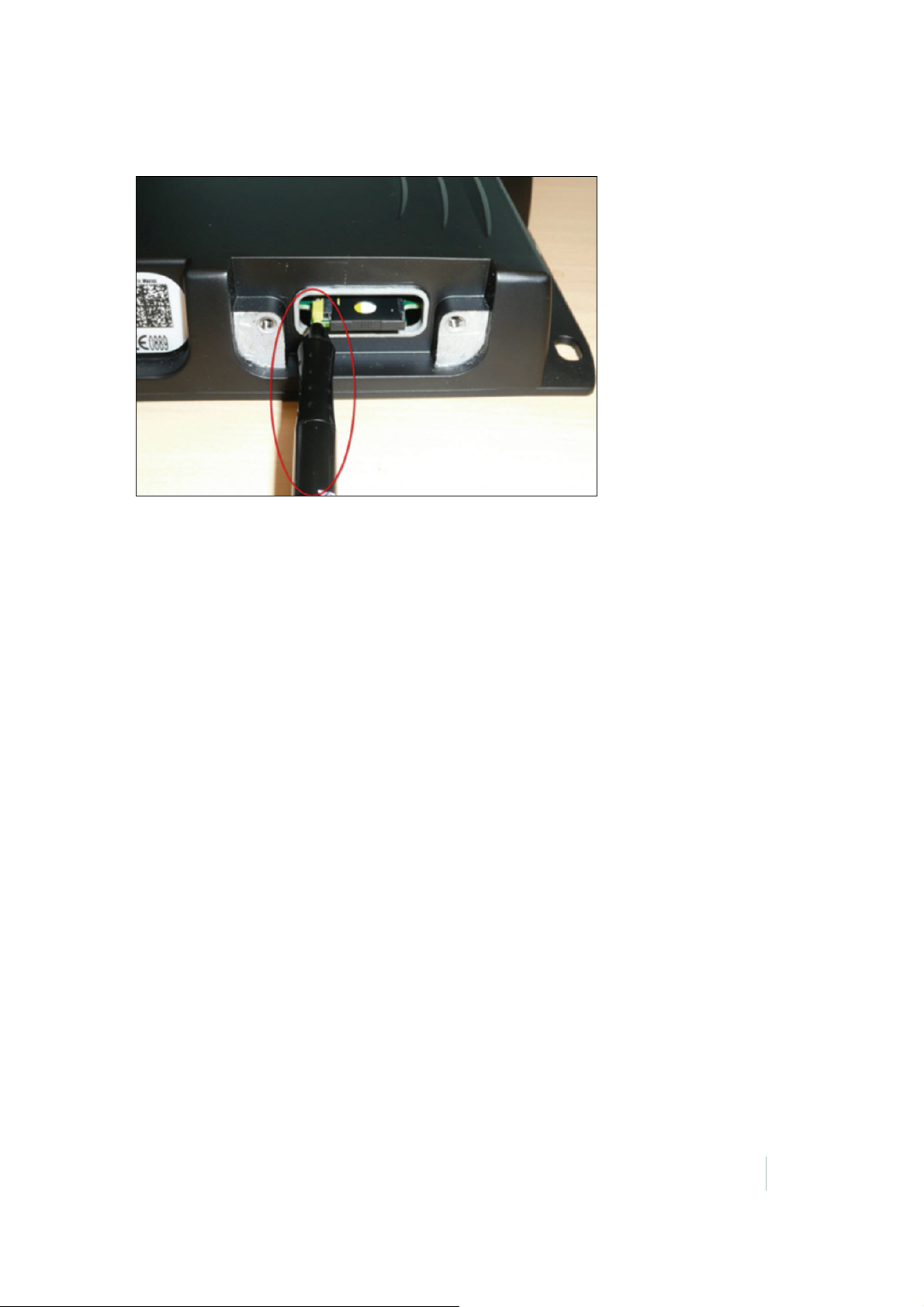
5. The SIM card is held in a removable carrier tray. To release the carrier tray, use a stylus or
ballpoint pen to press the yellow ejection button. Press the ejection button gently until the
carrier tray has moved outward approximately 5
SNM940 CONNECTED SITE GATEWAY INSTALLATION GUIDE
mm.
45
Page 46
8 – Installing the SIM Card
Do not press hard on the SIM ejection button, as it could damage the carrier tray locking
mechanism. If the button does not move easily, grab the carrier tray with needle nose pliers and
pull while gently pressing the ejection button.
SNM940 CONNECTED SITE GATEWAY INSTALLATION GUIDE
46
Page 47

Limited Warranty Terms and Conditions
Product Limited Warranty
Subject to the following terms and conditions, Trimble Navigation
Limited (“Trimble”) warrants that for a period of one (1) year from
date of purchase this Trimble product (the “Product”) will
substantially conform to Trimble's publicly available specifications
for the Product and that the hardware and any storage media
components of the Product will be substantially free from defects
in materials and workmanship.
Product Software
Product software, whether built into hardware circuitry as
firmware, provided as a standalone computer software product,
embedded in flash memory, or stored on magnetic or other
media, is licensed solely for use with or as an integral part of the
Product and is not sold. If accompanied by a separate end user
license agreement (“EULA”), use of any such software will be
subject to the terms of such end user license agreement (including
any differing limited warranty terms, exclusions, and limitations),
which shall control over the terms and conditions set forth in this
limited warranty.
Software Fixes
During the limited warranty period you will be entitled to receive
such Fixes to the Product software that Trimble releases and
makes commercially available and for which it does not charge
separately, subject to the procedures for delivery to purchasers of
Trimble products generally. If you have purchased the Product
from an authorized Trimble dealer rather than from Trimble
directly, Trimble may, at its option, forward the software Fix to the
Trimble dealer for final distribution to you. Minor Updates, Major
Upgrades, new products, or substantially new software releases,
as identified by Trimble, are expressly excluded from this update
process and limited warranty. Receipt of software Fixes or other
enhancements shall not serve to extend the limited warranty
period.
For purposes of this warranty the following definitions shall apply:
(1) “Fix(es)” means an error correction or other update created to
fix a previous software version that does not substantially conform
to its Trimble specifications; (2) “Minor Update” occurs when
enhancements are made to current features in a software
program; and (3) “Major Upgrade” occurs when significant new
features are added to software, or when a new product containing
new features replaces the further development of a current
product line. Trimble reserves the right to determine, in its sole
discretion, what constitutes a Fix, Minor Update, or Major
Upgrade.
Warranty Remedies
If the Trimble Product fails during the warranty period for reasons
covered by this limited warranty and you notify Trimble of such
failure during the warranty period, Trimble will repair OR replace
the nonconforming Product with new, equivalent to new, or
reconditioned parts or Product, OR refund the Product purchase
price paid by you, at Trimble’s option, upon your return of the
Product in accordance with Trimble's product return procedures
then in effect.
How to Obtain Warranty Service
To obtain warranty service for the Product, please contact your
local Trimble authorized dealer. Alternatively, you may contact
Trimble to request warranty service at +1-408-481-6940 (24 hours
a day) or e-mail your request to
Please be prepared to provide:
– your name, address, and telephone numbers
– proof of purchase
– a copy of this Trimble warranty
– a description of the nonconforming Product including the model
number
– an explanation of the problem
The customer service representative may need additional
information from you depending on the nature of the problem.
Warranty Exclusions and Disclaimer
This Product limited warranty shall only apply in the event and to
the extent that (a) the Product is properly and correctly installed,
configured, interfaced, maintained, stored, and operated in
accordance with Trimble's applicable operator's manual and
specifications, and; (b) the Product is not modified or misused.
This Product limited warranty shall not apply to, and Trimble shall
not be responsible for, defects or performance problems resulting
from (i) the combination or utilization of the Product with
hardware or software products, information, data, systems,
interfaces, or devices not made, supplied, or specified by Trimble;
(ii) the operation of the Product under any specification other
than, or in addition to, Trimble's standard specifications for its
products; (iii) the unauthorized installation, modification, or use of
the Product; (iv) damage caused by: accident, lightning or other
electrical discharge, fresh or salt water immersion or spray
(outside of Product specifications); or exposure to environmental
conditions for which the Product is not intended; (v) normal wear
and tear on consumable parts (e.g., batteries); or (vi) cosmetic
damage. Trimble does not warrant or guarantee the results
obtained through the use of the Product, or that software
components will operate error free.
NOTICE REGARDING PRODUCTS EQUIPPED WITH TECHNOLOGY
CAPABLE OF TRACKING SATELLITE SIGNALS FROM SATELLITE BASED
AUGMENTATION SYSTEMS (SBAS) (WAAS/EGNOS, AND MSAS),
OMNISTAR, GPS, MODERNIZED GPS OR GLONASS SATELLITES, OR FROM
IALA BEACON SOURCES: TRIMBLE IS NOT RESPONSIBLE FOR THE
OPERATION OR FAILURE OF OPERATION OF ANY SATELLITE BASED
POSITIONING SYSTEM OR THE AVAILABILITY OF ANY SATELLITE BASED
POSITIONING SIGNALS.
THE FOREGOI NG LIMITED WARRANTY TERMS STATE TRIMBLE’S ENTIRE
LIABILITY, AND YOUR EXCLUSIVE REMEDIES, RELATING TO THE TRIMBLE
PRODUCT. EXCEPT AS OTHERWISE EXPRESSLY PROVIDED HEREIN, THE
PRODUCT, AND ACCOMPANYING DOCUMENTATION AND MATERIALS ARE
PROVIDED “AS-IS” AND WITHOUT EXPRESS OR IMPLIED WARRANTY OF ANY
KIND, BY EITHER TRIMBLE OR ANYONE WHO HAS BEEN INVOLVED IN ITS
CREATION, PRODUCTION, INSTALLATION, OR DISTRIBUTION, INCLUDING, BUT
NOT LIMITED TO, THE IMPLIED WARRANTIES OF MERCHANTABILITY AND
FITNESS FOR A PARTICULAR PURPOSE, TITLE, AND NONINFRINGEMENT. THE
STATED EXPRESS WARRANTIES ARE IN LIEU OF ALL OBLIGATIONS OR
LIABILITIES ON THE PART OF TRIMBLE ARISING OUT OF, OR IN CONNECTION
WITH, ANY PRODUCT. BECAUSE SOME STATES AND JURISDICTIONS DO NOT
ALLOW LIMITATIONS ON DURATION OR THE EXCLUSION OF AN IMPLIED
WARRANTY, THE ABOVE LIMITATION MAY NOT APPLY OR FULLY APPLY TO
YOU.
Limitation of Liability
TRIMBLE'S ENTIRE LIABILITY UNDER ANY PROVISION HEREIN SHALL BE
LIMITED TO THE AMOUNT PAID BY YOU FOR THE PRODUCT. TO THE
MAXIMUM EXTENT PERM ITTED BY APPLICABLE LAW, IN NO EVENT SHALL
TRIMBLE OR ITS SUPPLIERS BE LIABLE FOR ANY INDIRECT, SPECIAL,
INCIDENTAL, OR CONSEQUENTIAL DAMAGE WHATSOEVER UNDER ANY
CIRCUMSTANCE OR LEGAL THEORY RELATING IN ANYWAY TO THE PRODUCTS,
SOFTWARE AND ACCOMPANYING DOCUMENTATION AND MATERIALS,
(INCLUDING, WITHOUT LIMITATION, DAMAGES FOR LOSS OF BUSINESS
PROFITS, BUSINESS INTERRUPTION, LOSS OF DATA, OR ANY OTHER
PECUNIARY LOSS), REGARDLESS OF WHETHER TRIMBLE HAS BEEN ADVISED
OF THE POSSIBILITY OF ANY SUCH LOSS AND REGARD LESS OF THE COURSE OF
DEALING WHICH DEVELOPS OR HAS DEVELOPED BETWEEN YOU AND
TRIMBLE. BECAUSE SOME STATES AND JURISDICTIONS DO NOT ALLOW THE
EXCLUSION OR LIMITATION OF LIABILITY FOR CONSEQUENTIAL OR
INCIDENTAL DAMAGES, THE ABOVE LIMITATION MAY NOT APPLY OR FULLY
APPLY TO YOU.
PLEASE NOTE: THE ABOVE TRIMBLE LIMITED WARRANTY PROVISIONS
WILL NOT APPLY TO PRODUCTS PURCHASED IN THOSE JURISDICTIONS
(E.G., MEMBER STATES OF THE EUROPEAN ECONOMIC AREA) IN
WHICH PRODUCT WARRANTIES ARE THE RESPONSI BILITY OF THE LOCAL
TRIMBLE AUTHORIZED DEALER FROM WHOM THE PRODUCTS ARE
ACQUIRED. IN SUCH A CASE, PLEASE CONTACT YOUR LOCAL TRIMBLE
AUTHORIZED DEALER FOR APPLICABLE WARRANTY INFORMATION.
Official Language
THE OFFICIAL LANGUAGE OF THESE TERMS AND CONDITIONS IS ENGLISH. IN
THE EVENT OF A CONFLICT BETWEEN ENGLISH AND OTHER LANGUAGE
VERSIONS, THE ENGLISH LANGUAGE SHALL CONTROL.
Registration
To receive information regarding updates and new products,
please contact your local Trimble authorized dealer or visit the
Trimble website at www.trimble.com/register. Upon registration
you may select the newsletter, upgrade, or new product
information you desire.
SNM940 CONNECTED SITE GATEWAY INSTALLATION GUIDE
47
Page 48

Software Components
This Trimble software contains Qt 4.5 libraries licensed under the
GNU Lesser General Public License (LGPL).
GNU LESSER GENERAL PUBLIC LICENSE
Version 2.1, February 1999
Copyright c 1991, 1999 Free Software Foundation, Inc.
51 Franklin Street, Fifth Floor, Boston, MA 02110-1301
USA
Everyone is permitted to copy and distribute verbatim copies of
this license document, but changing it is not allowed. [This is the
first released version of the Lesser GPL. It also counts as the
successor of the GNU Library Public License, version 2, hence the
version number 2.1.] Preamble The licenses for most software are
designed to take away your freedom to share and change it. By
contrast, the GNU General Public Licenses are intended to
guarantee your freedom to share and change free software-to
make sure the software is free for all its users. This license, the
Lesser General Public License, applies to some specially
designated software packages-typically libraries-of the Free
Software Foundation and other authors who decide to use it. You
can use it too, but we suggest you first think carefully about
whether this license or the ordinary General Public License is the
better strategy to use in any particular case, based on the
explanations below. When we speak of free software, we are
referring to freedom of use, not price. Our General Public Licenses
are designed to make sure that you have the freedom to distribute
copies of free software (and charge for this service if you wish);
that you receive source code or can get it if you want it; that you
can change the software and use pieces of it in new free
programs; and that you are informed that you can do these things.
To protect your rights, we need to make restrictions that forbid
distributors to deny you these rights or to ask you to surrender
these rights. These restrictions translate to certain responsibilities
for you if you distribute copies of the library or if you modify it.
For example, if you distribute copies of the library, whether gratis
or for a fee, you m ust give the recipients all the rig hts that we gave
you. You must make sure that they, too, receive or can get the
source code. If you link other code with the library, you must
provide complete object files to the recipients, so that they can
relink them with the library after making changes to the library
and recompiling it. And you must show them these terms so they
know their rights. We protect your rights with a two-step method:
(1) we copyright the library, and (2) we offer you this license,
which gives you legal permission to copy, distribute and/ or
modify the library.
To protect each distributor, we want to make it very clear that
there is no warranty for the free library. Also, if the library is
modified by someone else and passed on, the recipients should
know that what they have is not the original version, so that the
original author's reputation will not be affected by problems that
might be introduced by others. Finally, software patents pose a
constant threat to the existence of any free program. We wish to
make sure that a company cannot effectively restrict the users of a
free program by obtaining a restrictive license from a patent
holder. Therefore, we insist that any patent license obtained for a
version of the library must be consistent with the full freedom of
use specified in this license.
Most GNU software, including some libraries, is covered by the
ordinary GNU General Public License. This license, the GNU Lesser
General Public License, applies to certain designated libraries, and
is quite different from the ordinary General Public License. We use
this license for certain libraries in order to permit linking those
libraries into non-free programs. When a program is linked with a
library, whether statically or using a shared library, the
combination of the two is legally speaking a combined work, a
derivative of the original library. The ordinary General Public
License therefore permits such linking only if the entire
combination fits its criteria of freedom. The Lesser General Public
License permits more lax criteria for linking other code with the
library.
We call this license the "Lesser" General Public License because it
does Less to protect the user's freedom than the ordinary General
Public License. It also provides other free software developers Less
of an advantage over competing non-free programs. These
disadvantages are the reason we use the ordinary General Public
License for many libraries. However, the Lesser license provides
advantages in certain special circumstances. For example, on rare
occasions, there may be a special need to encourage the widest
possible use of a certain library, so that it becomes a de-facto
standard. To achieve this, non-free programs must be allowed to
use the library. A more frequent case is that a free library does the
same job as widely used non-free libraries. In this case, there is
little to gain by limiting the free library to free software only, so we
use the Lesser General Public License. In other cases, permission
to use a particular library in nonfree programs enables a greater
number of people to use a large body of free software. For
example, permission to use the GNU C Library in non-free
programs enables many more people to use the whole GNU
operating system, as well as its variant, the GNU/Linux operating
system. Although the Lesser General Public License is Less
protective of the users' freedom, it does ensure that the user of a
program that is linked with the Library has the freedom and the
wherewithal to run that program using a modified version of the
Library. Pay close attention to the difference between a "work
based on the library" and a "work that uses the library". The
former contains code derived from the library, whereas the latter
must be combined with the library in order to run. GNU LESSER
GENERAL PUBLIC LICENSE TERMS AND CONDITIONS FOR
COPYING, DISTRIBUTION AND MODIFICATION. This License
Agreement applies to any software library or other program which
contains a notice placed by the copyright holder or other
authorized party saying it may be distributed under the terms of
this Lesser General Public License (also called "this License"). Each
licensee is addressed as "you". A "library" means a collection of
software functions and/or data prepared so as to be conveniently
linked with application programs (which use some of those
functions and data) to form executables. The "Library", below,
refers to any such software library or work which has been
distributed under these terms. A "work based on the Library"
means either the Library or any derivative work under copyright
law: that is to say, a work containing the Library or a portion of it,
either verbatim or with modifications and/or translated
straightforwardly into another language. (Hereinafter, translation
is included without limitation in the term "modification".) "Source
code" for a work means the preferred form of the work for making
modifications to it. For a library, complete source code means all
the source code for all modules it contains, plus any associated
interface definition files, plus the scripts used to control
compilation and installation of the library. Activities other than
copying, distribution and modification are not covered by this
License; they are outside its scope. The act of running a program
using the Library is not restricted, and output from such a program
is covered only if its contents constitute a work based on the
Library (independent of the use of the Library in a tool for writing
it). Whether that is true depends on what the Library does and
what the program that uses the Library does. 1. You may copy and
distribute verbatim copies of the Library's complete source code
as you receive it, in any medium, provided that you conspicuously
and appropriately publish on each copy an appropriate copyright
notice and disclaimer of warranty; keep intact all the notices that
refer to this License and to the absence of any warranty; and
distribute a copy of this License along with the Library.
You may charge a fee for the physical act of transferring a copy,
and you may at your option offer warranty protection in exchange
for a fee. 2. You may modify your copy or copies of the Library or
any portion of it, thus forming a work based on the Library, and
copy and distribute such modifications or work under the terms of
Section 1 above, provided that you also meet all of these
conditions: a) The modified work must itself be a software library.
b) You must cause the files modified to carry prominent notices
stating that you changed the files and the date of any change. c)
You must cause the whole of the work to be licensed at no charge
to all
third parties under the terms of this License. d) If a facility in the
modified Library refers to a function or a table of data to be
supplied by an application program that uses the facility, other
than as an argument passed when the facility is invoked, then you
must make a good
faith effort to ensure that, in the event an application does not
supply such function or table, the facility still operates, and
performs whatever part of its purpose remains meaningful. (For
example, a function in a library to compute square roots has a
purpose that is entirely well-defined independent of the
application. Therefore, Subsection 2d requires that any
application-supplied function or table used by this function must
be optional: if the application does not supply it, the square root
function must still compute square roots.) These requirements
apply to the modified work as a whole. If identifiable sections of
that work are not derived from the Library, and can be reasonably
considered independent and separate works in themselves, then
this License, and its terms, do not apply to those sections when
you distribute them as separate works. But when you distribute
the same sections as part of a whole which is a work based on the
SNM940 CONNECTED SITE GATEWAY INSTALLATION GUIDE
48
Page 49

Library, the distribution of the whole must be on the terms of this
License, whose permissions for other licensees extend to the
+entire whole, and thus to each and every part regardless of who
wrote it. Thus, it is not the intent of this section to claim rights or
contest your rights to work written entirely by you; rather, the
intent is to exercise the right to control the distribution of
derivative or collective works based on the Library. In addition,
mere aggregation of another work not based on the Library with
the Library (or with a work based on the Library) on a volume of a
storage or distribution medium does not bring the other work
under the scope of this License. 3. You may opt to apply the terms
of the ordinary GNU General Public License instead of this License
to a given copy of the Library. To do this, you must alter all the
notices that refer to this License, so that they refer to the ordinary
GNU General Public License, version 2, instead of to this License.
(If a newer version than version 2 of the ordinary GNU General
Public License has appeared, then you can specify that version
instead if you wish.) Do not make any other change in these
notices. Once this change is made in a given copy, it is irreversible
for that copy, so the ordinary GNU General Public License applies
to all subsequent copies and derivative works made from that
copy.
This option is useful when you wish to copy part of the code of the
Library into a program that is not a library. 4. You may copy and
distribute the Library (or a portion or derivative of it, under
Section 2) in object code or executable form under the terms of
Sections 1 and 2 above provided that you accompany it with the
complete corresponding machine-readable source code, which
must be distributed under the terms of Sections 1 and 2 above on
a medium customarily used for software interchange.
If distribution of object code is made by offering access to copy
from a designated place, then offering equivalent access to copy
the source code from the same place satisfies the requirement to
distribute the source code, even though third parties are not
compelled to copy the source along with the object code. 5. A
program that contains no derivative of any portion of the Library,
but is designed to work with the Library by being compiled or
linked with it, is called a "work that uses the Library". Such a work,
in isolation, is not a derivative work of the Library, and therefore
falls outside the scope of this License. However, linking a "work
that uses the Library" with the Library creates an executable that
is a derivative of the Library (because it contains portions of the
Library), rather than a "work that uses the library". The executable
is therefore covered by this License. Section 6 states terms for
distribution of such executables. When a "work that uses the
Library" uses material from a header file that is part of the Library,
the object code for the work may be a derivative work of the
Library even though the source code is not. Whether this is true is
especially significant if the work can be linked without the Library,
or if the work is itself a library. The threshold for this to be true is
not precisely defined by law. If such an object file uses only
numerical parameters, data structure layouts and accessors, and
small macros and small inline functions (ten lines or less in length),
then the use of the object file is unrestricted, regardless of
whether it is legally a derivative work. (Executables containing this
object code plus portions of the Library will still fall under Section
6.) Otherwise, if the work is a derivative of the Library, you may
distribute the object code for the work under the terms of Section
6. Any executables containing that work also fall under Section 6,
whether or not they are linked directly with the Library itself. 6. As
an exception to the Sections above, you may also combine or link
a "work that uses the Library" with the Library to produce a work
containing portions of the Library, and distribute that work under
terms of your choice, provided that the terms permit modification
of the work for the customer's own use and reverse engineering
for debugging such modifications. You must give prominent notice
with each copy of the work that the Library is used in it and that
the Library and its use are covered by this License. You must
supply a copy of this License. If the work during execution displays
copyright notices, you must include the copyright notice for the
Library among them, as well as a reference directing the user to
the copy of this License. Also, you must do one of these things: a)
Accompany the work with the complete corresponding machinereadable source code for the Library including whatever changes
were used in the work (which must be distributed under Sections
1 and 2 above); and, if the work is an executable linked with the
Library, with the complete machine readable "work that uses the
Library", as object code and/or source code, so that the user can
modify the Library and then relink to produce a modified
executable containing the modified Library. (It is understood that
the user who changes the contents of definitions files in the
Library will not necessarily be able to recompile the application to
use the modified definitions.) b) Use a suitable shared library
mechanism for linking with the Library. A suitable mechanism is
one that (1) uses at run time a copy of the library already present
on the user's computer system, rather than copying library
functions into the executable, and (2) will operate properly with a
modified version of the library, if the user installs one, as long as
the modified version is interface-compatible with the version that
the work was made with. c) Accompany the work with a written
offer, valid for at least three years, to give the same user the
materials specified in Subsection 6a, above, for a charge no more
than the cost of performing this distribution. d) If distribution of
the work is made by offering access to copy from a designated
place, offer equivalent access to copy the above specified
materials from the same place. e) Verify that the user has already
received a copy of these materials or that you have already sent
this user a copy. For an executable, the required form of the "work
that uses the Library" must include any data and utility programs
needed for reproducing the executable from it. However, as a
special exception, the materials to be distributed need not include
anything that is normally distributed (in either source or binary
form) with the major components (compiler, kernel, and so on) of
the operating system on which the executable runs, unless that
component itself accompanies the executable. It may happen that
this requirement contradicts the license restrictions of other
proprietary libraries that do not normally accompany the
operating system. Such a contradiction means you cannot use
both them and the Library together in an executable that you
distribute. 7. You may place library facilities that are a work based
on the Library side-by-side in a single library together with other
library facilities not covered by this License, and distribute such a
combined library, provided that the separate distribution of the
work based on the Library and of the other library facilities is
otherwise permitted, and provided that you do these two things:
a) Accompany the combined library with a copy of the same work
based on the Library, uncombined with any other library facilities.
This must be distributed under the terms of the Sections above. b)
Give prominent notice with the combined library of the fact that
part of it is a work based on the Library, and explaining where to
find the accompanying uncombined form of the same work. 8. You
may not copy, modify, sublicense, link with, or distribute the
Library except as expressly provided under this License. Any
attempt otherwise to copy, modify, sublicense, link with, or
distribute the Library is void, and will automatically terminate
your rights under this License. However, parties who have
received copies, or rights, from you under this License will not
have their licenses terminated so long as such parties remain in
full compliance. 9. You are not required to accept this License,
since you have not signed it. However, nothing else grants you
permission to modify or distribute the Library or its derivative
works. These actions are prohibited by law if you do not accept
this License. Therefore, by modifying or distributing the Library (or
any work based on the Library), you indicate your acceptance of
this License to do so, and all its terms and conditions for copying,
distributing or modifying the Library or works based on it.
10. Each time you redistribute the Library (or any work based on
the Library), the recipient automatically receives a license from
the original licensor to copy, distribute, link with or modify the
Library subject to these terms and conditions. You may not impose
any further restrictions on the recipients' exercise of the rights
granted herein. You are not responsible for enforcing compliance
by third parties with this License.
SNM940 CONNECTED SITE GATEWAY INSTALLATION GUIDE
49
 Loading...