

Page 1

TOTAL STATION USER GUIDE
Trimble® SCS900 Site Controller
Software
Page 2

NORTH AMERICA
Trimble Construction Division
5475 Kellenburger Road
Dayton, Ohio 45424
USA
800-538-7800 (Toll Free)
+1-937-245-5600 Phone
+1-937-233-9004 Fax
EUROPE
Trimble GmbH
Am Prime Parc 11
65479 Raunheim
GERMANY
+49-6142-2100-0 Phone
+49-6142-2100-550 Fax
ASIA - PACIFIC
Trimble Navigation Australia
PTY Limited
Level 1/120 Wickham Street
Fortitude Valley, QLD 4006
AUSTRALIA
+61-7-3216-0044 Phone
+61-7-3216-0088 Fax
www.trimble.com
Page 3

TOTAL STATION USER GUIDE
Trimble® SCS900 Site Controller Software
Version 2.50
Revision A
February 2009
F
Page 4

Contact Information
Trimble Navigation Limited
Engineering & Construction Group
5475 Kellenburger Road
Dayton, Ohio 45424-1099
USA
800-538-7800 (toll free in USA)
+1-937-245-5600 Phone
+1-937-233-9004 Fax
www.trimble.com
Support Offices
For registered product users:
1 800 SOS 4 TAC (USA-based support)
Legal Notices
Copyright and Trademarks
© 2007–2009, Trimble Navigation Limited. All rights reserved.
Trimble, the Globe & Triangle logo, Autolock, BladePro, SiteVision,
Terramodel, Tracklight, and TSC2 are trademarks of Trimble Navigation
Limited, registered in the United States and in other countries. VRS and
SiteNet are trademarks of Trimble Navigation Limited.
The Bluetooth word mark and logos are owned by the Bluetooth SIG,
Inc. and any use of such marks by Trimble Navigation Limited is under
license.
Microsoft, Windows, and Windows Mobile are either registered
trademarks or trademarks of Microsoft Corporation in the United States
and/or other countries.
All other trademarks are the property of their respective owners.
The Trimble SCS900 Site Controller software is covered by the following
U.S. patents: 6021376, 6016118, 5986604, 5614913 and other patents
pending.
Release Notice
This is the February 2009 release (Revision A) of the SCS900 Site
Controller Software Total Station User Guide. It applies to version 2.50 of
the SCS900 Site Controller software.
Product Limited Warranty Information
For applicable product Limited Warranty information, please refer to
Legal Notices in the Release Notes, or consult your local Trimble
authorized dealer.
2 SCS900 Site Controller Software Total Station User Guide
Page 5
Safety Information
Before you use the Trimble® Site Controller software, make sure that you have read
and understood all safety requirements, as well as all equipment and job site safety
requirements.
Warnings
C
WARNING – This alert warns of a potential hazard which, if not avoided, can cause severe
injury.
Cautions
Always observe safety instructions that are presented in the following format:
C
CAUTION – A Caution alerts you to a possible risk of damage to the equipment and/or
loss of data. A Caution describes how to protect the equipment and/or data from this risk.
Vehicle safety
C
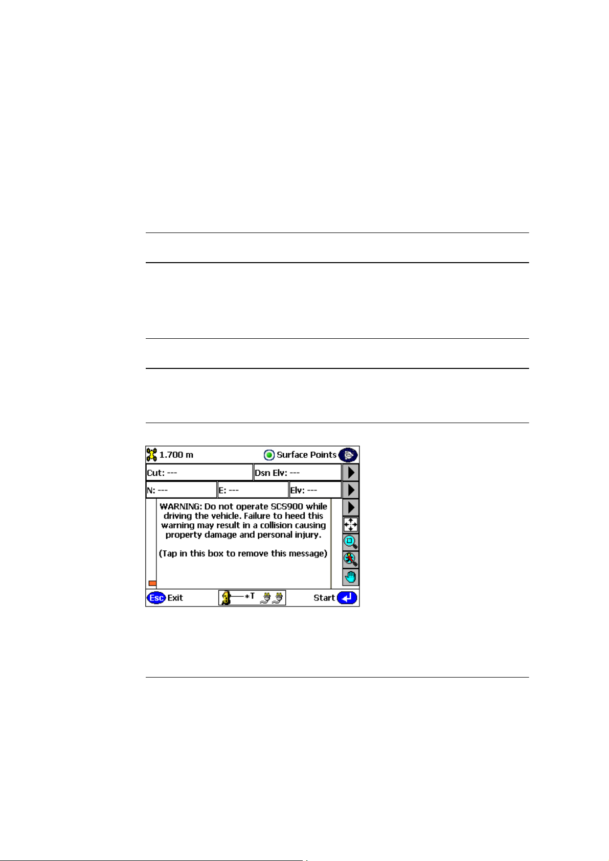
WARNING – When you select the Vehicle mode, the following warning message appears:
Do not interact with the touch screen, keyboard, or software in any way while the vehicle
is moving. While the vehicle is moving, the software provides a continuous display of
position and data that can be seen at a glance. Operating the device or interacting with
the software while the vehicle is moving can be a distraction for the operator, and may
result in collision causing property damage or personal injury.
SCS900 Site Controller Software Total Station User Guide 3
Page 6

Safety Information
Servicing
Do not attempt to repair a Trimble ACU, TSC2®, or Trimble CU controller. There are no
user-serviceable parts inside. To arrange for a controller to be serviced, please contact
your Trimble dealer.
Accessories
C
CAUTION – Use only approved accessories with this equipment. In general, all cables must
be high quality, shielded, correctly terminated, and normally restricted to two meters
(6.56 feet) in length. AC adaptors approved for this product employ special provisions to
avoid radio interference and should not be altered or substituted. Unapproved
modifications or operations beyond or in conflict with these instructions for use may void
authorization by the authorities to operate the equipment.
4 SCS900 Site Controller Software Total Station User Guide
Page 7

Contents 1
Safety Information . . . . . . . . . . . . . . . . . . . . . . . . . . . . . . . . 3
Warnings . . . . . . . . . . . . . . . . . . . . . . . . . . . . . . . . . . . . . . . . . . . . . . . . . . . . . . . 3
Cautions. . . . . . . . . . . . . . . . . . . . . . . . . . . . . . . . . . . . . . . . . . . . . . . . . . . . . . . . 3
Vehicle safety. . . . . . . . . . . . . . . . . . . . . . . . . . . . . . . . . . . . . . . . . . . . . . . . . . . . . 3
Servicing . . . . . . . . . . . . . . . . . . . . . . . . . . . . . . . . . . . . . . . . . . . . . . . . . . . . . . . 4
Accessories . . . . . . . . . . . . . . . . . . . . . . . . . . . . . . . . . . . . . . . . . . . . . . . . . . . . . . 4
1 Introduction . . . . . . . . . . . . . . . . . . . . . . . . . . . . . . . . . . . . 9
About the SCS900 Site Controller Software. . . . . . . . . . . . . . . . . . . . . . . . . . . . . . . . . . 9
Related information . . . . . . . . . . . . . . . . . . . . . . . . . . . . . . . . . . . . . . . . . . . . . . . 10
Technical assistance . . . . . . . . . . . . . . . . . . . . . . . . . . . . . . . . . . . . . . . . . . . . . . . 10
Your comments . . . . . . . . . . . . . . . . . . . . . . . . . . . . . . . . . . . . . . . . . . . . . . . . . . 10
2 Connecting to a Total Station and Setting up the Controller . . . . . . . . 11
Starting the SCS900 software. . . . . . . . . . . . . . . . . . . . . . . . . . . . . . . . . . . . . . . . . . 12
Connecting to a total station . . . . . . . . . . . . . . . . . . . . . . . . . . . . . . . . . . . . . . . . . . 12
Leveling the total station . . . . . . . . . . . . . . . . . . . . . . . . . . . . . . . . . . . . . . . . 13
Correcting for atmospheric conditions . . . . . . . . . . . . . . . . . . . . . . . . . . . . . . . 14
Selecting the external battery type . . . . . . . . . . . . . . . . . . . . . . . . . . . . . . . . . . 15
Setting up the controller. . . . . . . . . . . . . . . . . . . . . . . . . . . . . . . . . . . . . . . . . . . . . 15
Units and Formats option . . . . . . . . . . . . . . . . . . . . . . . . . . . . . . . . . . . . . . . 16
Instrument Setup Tolerances option. . . . . . . . . . . . . . . . . . . . . . . . . . . . . . . . . 17
Data Output Options . . . . . . . . . . . . . . . . . . . . . . . . . . . . . . . . . . . . . . . . . . 18
3 Creating a Site and a Work Order . . . . . . . . . . . . . . . . . . . . . . . 21
Organizing data . . . . . . . . . . . . . . . . . . . . . . . . . . . . . . . . . . . . . . . . . . . . . . . . . . 22
Sites . . . . . . . . . . . . . . . . . . . . . . . . . . . . . . . . . . . . . . . . . . . . . . . . . . . . . 22
Designs . . . . . . . . . . . . . . . . . . . . . . . . . . . . . . . . . . . . . . . . . . . . . . . . . . . 22
Work orders . . . . . . . . . . . . . . . . . . . . . . . . . . . . . . . . . . . . . . . . . . . . . . . . 23
Global data. . . . . . . . . . . . . . . . . . . . . . . . . . . . . . . . . . . . . . . . . . . . . . . . . 24
Creating a new work order and a new site . . . . . . . . . . . . . . . . . . . . . . . . . . . . . . . . . 24
Opening an existing work order . . . . . . . . . . . . . . . . . . . . . . . . . . . . . . . . . . . . . . . . 28
Completing a work order . . . . . . . . . . . . . . . . . . . . . . . . . . . . . . . . . . . . . . . . . . . . 28
4 Main Menu Structure . . . . . . . . . . . . . . . . . . . . . . . . . . . . . . 29
Work Orders menu . . . . . . . . . . . . . . . . . . . . . . . . . . . . . . . . . . . . . . . . . . . . . . . . 30
Measurement menu . . . . . . . . . . . . . . . . . . . . . . . . . . . . . . . . . . . . . . . . . . . . . . . 31
Stakeout menu. . . . . . . . . . . . . . . . . . . . . . . . . . . . . . . . . . . . . . . . . . . . . . . . . . . 32
Settings menu . . . . . . . . . . . . . . . . . . . . . . . . . . . . . . . . . . . . . . . . . . . . . . . . . . . 33
Volume & COGO menu . . . . . . . . . . . . . . . . . . . . . . . . . . . . . . . . . . . . . . . . . . . . . 34
System Setup menu . . . . . . . . . . . . . . . . . . . . . . . . . . . . . . . . . . . . . . . . . . . . . . . 35
5 Setting up Control Points . . . . . . . . . . . . . . . . . . . . . . . . . . . . 37
Types of control points . . . . . . . . . . . . . . . . . . . . . . . . . . . . . . . . . . . . . . . . . . . . . 38
SCS900 Site Controller Software Total Station User Guide 5
Page 8

Contents
Entering control point coordinates . . . . . . . . . . . . . . . . . . . . . . . . . . . . . . . . . . . . . . 38
6 Establishing the Position and Orientation of the Total Station
on the Jobsite (Station Establishment)41
Setting up at an arbitrary location . . . . . . . . . . . . . . . . . . . . . . . . . . . . . . . . . . . . . . 43
Setting up on a known point . . . . . . . . . . . . . . . . . . . . . . . . . . . . . . . . . . . . . . . . . . 48
Reading station setup data from the total station. . . . . . . . . . . . . . . . . . . . . . . . . . . . . 53
Completing a station establishment where the height of the setup point has not been
determined . . . . . . . . . . . . . . . . . . . . . . . . . . . . . . . . . . . . . . . . . . . . . . . . . . . 54
7 Setting Up an ATS or SPSx30 Total Station for Machine Control . . . . . . 57
Using the ATS or SPSx30 UTS for machine control applications . . . . . . . . . . . . . . . . . . . 58
8 Using Basic Mode. . . . . . . . . . . . . . . . . . . . . . . . . . . . . . . . . 63
Icon panel. . . . . . . . . . . . . . . . . . . . . . . . . . . . . . . . . . . . . . . . . . . . . . . . . . . . . . 64
Total Station Basic mode . . . . . . . . . . . . . . . . . . . . . . . . . . . . . . . . . . . . . . . . . . . . 65
DR . . . . . . . . . . . . . . . . . . . . . . . . . . . . . . . . . . . . . . . . . . . . . . . . . . . . . . 66
EDM mode . . . . . . . . . . . . . . . . . . . . . . . . . . . . . . . . . . . . . . . . . . . . . . . . . 66
Tracklight. . . . . . . . . . . . . . . . . . . . . . . . . . . . . . . . . . . . . . . . . . . . . . . . . . 66
Level . . . . . . . . . . . . . . . . . . . . . . . . . . . . . . . . . . . . . . . . . . . . . . . . . . . . . 67
Turn-to . . . . . . . . . . . . . . . . . . . . . . . . . . . . . . . . . . . . . . . . . . . . . . . . . . . 67
Autolock mode . . . . . . . . . . . . . . . . . . . . . . . . . . . . . . . . . . . . . . . . . . . . . . 68
Search . . . . . . . . . . . . . . . . . . . . . . . . . . . . . . . . . . . . . . . . . . . . . . . . . . . . 69
Laser. . . . . . . . . . . . . . . . . . . . . . . . . . . . . . . . . . . . . . . . . . . . . . . . . . . . . 70
Joystick . . . . . . . . . . . . . . . . . . . . . . . . . . . . . . . . . . . . . . . . . . . . . . . . . . . 71
Set HA . . . . . . . . . . . . . . . . . . . . . . . . . . . . . . . . . . . . . . . . . . . . . . . . . . . . 71
HD/VD or VA/SD mode. . . . . . . . . . . . . . . . . . . . . . . . . . . . . . . . . . . . . . . . . 72
9 Advanced Features. . . . . . . . . . . . . . . . . . . . . . . . . . . . . . . . 73
Stockpile scan . . . . . . . . . . . . . . . . . . . . . . . . . . . . . . . . . . . . . . . . . . . . . . . . . . . 74
Profile scan . . . . . . . . . . . . . . . . . . . . . . . . . . . . . . . . . . . . . . . . . . . . . . . . . . . . . 80
Automated measurement. . . . . . . . . . . . . . . . . . . . . . . . . . . . . . . . . . . . . . . . . . . . 87
10 Setting up the Total Station for Robotic Operation . . . . . . . . . . . . . 97
Starting with the controller connected directly to the total station. . . . . . . . . . . . . . . . . . 98
Starting with the controller connected over the radio to the total station . . . . . . . . . . . . .102
11 Rechecking the System Setup . . . . . . . . . . . . . . . . . . . . . . . . 105
Checking a control point using a prism . . . . . . . . . . . . . . . . . . . . . . . . . . . . . . . . . . .107
Checking a control point without a prism . . . . . . . . . . . . . . . . . . . . . . . . . . . . . . . . . 110
12 Measuring a Control Point . . . . . . . . . . . . . . . . . . . . . . . . . . 113
Measuring a new point . . . . . . . . . . . . . . . . . . . . . . . . . . . . . . . . . . . . . . . . . . . . .114
Measuring an existing control point . . . . . . . . . . . . . . . . . . . . . . . . . . . . . . . . . . . . . 116
13 Measuring Modes . . . . . . . . . . . . . . . . . . . . . . . . . . . . . . . 119
Measuring modes . . . . . . . . . . . . . . . . . . . . . . . . . . . . . . . . . . . . . . . . . . . . . . . . . 120
Standing mode . . . . . . . . . . . . . . . . . . . . . . . . . . . . . . . . . . . . . . . . . . . . . .120
6 SCS900 Site Controller Software Total Station User Guide
Page 9

Contents
Walking mode . . . . . . . . . . . . . . . . . . . . . . . . . . . . . . . . . . . . . . . . . . . . . . . 120
Vehicle mode . . . . . . . . . . . . . . . . . . . . . . . . . . . . . . . . . . . . . . . . . . . . . . .121
Averaging mode. . . . . . . . . . . . . . . . . . . . . . . . . . . . . . . . . . . . . . . . . . . . . .124
DR Single Point mode . . . . . . . . . . . . . . . . . . . . . . . . . . . . . . . . . . . . . . . . . .124
DR Scanning mode . . . . . . . . . . . . . . . . . . . . . . . . . . . . . . . . . . . . . . . . . . . .124
Changing the measuring mode . . . . . . . . . . . . . . . . . . . . . . . . . . . . . . . . . . . . . . . .124
14 Other Total Station Settings and Functions. . . . . . . . . . . . . . . . . 127
Target height and target type settings from the map view . . . . . . . . . . . . . . . . . . . . . . . 128
DR Target Settings dialog . . . . . . . . . . . . . . . . . . . . . . . . . . . . . . . . . . . . . . . . . . . . 129
Stakeout Settings menu . . . . . . . . . . . . . . . . . . . . . . . . . . . . . . . . . . . . . . . . . . . . . 130
General Stake Placement & Marking . . . . . . . . . . . . . . . . . . . . . . . . . . . . . . . .130
Auto Aim Option . . . . . . . . . . . . . . . . . . . . . . . . . . . . . . . . . . . . . . . . . . . . .131
COM Port Data Output Option . . . . . . . . . . . . . . . . . . . . . . . . . . . . . . . . . . . . . . . .132
Instrument Functions menu . . . . . . . . . . . . . . . . . . . . . . . . . . . . . . . . . . . . . . . . . .133
External Battery Type Settings option. . . . . . . . . . . . . . . . . . . . . . . . . . . . . . . .134
Atmospheric Corrections option . . . . . . . . . . . . . . . . . . . . . . . . . . . . . . . . . . . 135
Instrument Settings option. . . . . . . . . . . . . . . . . . . . . . . . . . . . . . . . . . . . . . .135
DR/IR target settings option. . . . . . . . . . . . . . . . . . . . . . . . . . . . . . . . . . . . . .136
Radio Settings option . . . . . . . . . . . . . . . . . . . . . . . . . . . . . . . . . . . . . . . . . . 137
15 Adjusting the Total Station . . . . . . . . . . . . . . . . . . . . . . . . . . 139
Types of checks . . . . . . . . . . . . . . . . . . . . . . . . . . . . . . . . . . . . . . . . . . . . . . . . . .140
Mechanical checks . . . . . . . . . . . . . . . . . . . . . . . . . . . . . . . . . . . . . . . . . . . .140
Electronic system checks . . . . . . . . . . . . . . . . . . . . . . . . . . . . . . . . . . . . . . . .140
Electronic/software driven checks . . . . . . . . . . . . . . . . . . . . . . . . . . . . . . . . . . 140
Compensator Calibration . . . . . . . . . . . . . . . . . . . . . . . . . . . . . . . . . . . . . . . . . . . . 141
HA VA Collimation test . . . . . . . . . . . . . . . . . . . . . . . . . . . . . . . . . . . . . . . . . . . . . 142
Trunnion Axis Tilt test . . . . . . . . . . . . . . . . . . . . . . . . . . . . . . . . . . . . . . . . . . . . . . 143
Tracker Collimation test. . . . . . . . . . . . . . . . . . . . . . . . . . . . . . . . . . . . . . . . . . . . . 144
SCS900 Site Controller Software Total Station User Guide 7
Page 10

Contents
8 SCS900 Site Controller Software Total Station User Guide
Page 11

Introduction 1
This SCS900 Site Controller Software Total Station
User Guide covers all aspects of the SCS900
software that relate to total station operation.
For measurement and stakeout operational
guidelines that are common to both total station
and GPS systems, please refer to the other
SCS900 guides that are available (see Related
information).
About the SCS900 Site Controller Software
The SCS900 software can be used with the
following systems:
• Total stations – The software can be used
either with a total station using Servo,
Autolock
technology.
• Precision GPS – Covers centimeter GPS
positioning techniques including Real-Time
Kinematic (RTK) using a site base station
(over radio), local base station (off-site over
the Internet, cell phone, or rebroadcast
radio), or a VRS
Internet, cell phone, or rebroadcast radio).
For more information, refer to the SCS900
Site Controller Software Precision GPS User
Guide.
®
, Robotic, or Reflectorless
™
network (VRS over the
CHAPTER
1
and MSAS), DGPS (reference station and
rover operations), OmniSTAR VBS, XP, or HP
services, and Location RTK (decimeter-level
RTK positioning). In addition, it includes
moving baseline operations to determine
both position and heading of a moving
vessel providing the ability to rapidly
position objects such as piling rigs, marine
dredgers, or bridge sections in real time. For
more information, refer to the SCS900 Site
Controller Software Location GPS User Guide.
The software is operated using a tablet PC ( for
the SCS900 Tablet Edition software), a Trimble
ACU, TSC2, or Trimble CU controller.
The SCS900 software supports the following total
stations:
• Trimble 5600 Total Station
• ATS Total Station
• SPS610 Total Station
• SPS700 Total Station
• SPS710 Total Station
• SPS630 Universal Total Station
• SPS730 Universal Total Station
• SPS930 Universal Total Station
• Location GPS – Covers decimeter to
submeter GPS positioning techniques
including Satellite Based Augmentation
Systems (SBAS) (such as WAAS, EGNOS,
SCS900 Site Controller Software Total Station User Guide 9
Page 12

1 Introduction
Related information
The following documents are available from the
SCS900 Documentation folder on
www.trimble.com:
• SCS900 Site Controller Software Office Guide
• SCS900 Site Controller Software Location GPS
User Guide
• SCS900 Site Controller Software Measurement
User Guide
• SCS900 Site Controller Software Precision GPS
User Guide
• SCS900 Site Controller Software Road and
Side Slope Stakeout User Guide
• SCS900 Site Controller Software Stakeout User
Guide
• SCS900 Site Controller Software Total Station
User Guide
• SCS900 Site Controller Software Release Notes
Technical assistance
If you have a problem and cannot find the
information you need in the product
documentation, contact your local Trimble
dealer.
Your comments
Feedback about the documentation helps us to
improve it with each revision. Please email your
comments to [email protected].
• SCS900 Site Controller Software Product
Registration Form
Tip – For convenience, Trimble recommends
B
that you install all documentation from the
website to the hard drive of the office
computer.
Each total station system has its own user guide
containing instrument specific information. Use
this manual with the material contained in those
guides.
10 SCS900 Site Controller Software Total Station User Guide
Page 13

CHAPTER
2
Connecting to a Total Station and Setting up the Controller
In this chapter:
Starting the SCS900 software
Connecting to a total station
Setting up the controller
This chapter guides you through the following
actions you must do before you start working in
the field:
1. Start the SCS900 software.
2. Check that the controller is connected to
the total station.
3. Level the total station. If you enable the
compensator inside the total station, it
automatically corrects for instrument
mislevel.
4. Correct the total station for atmospheric
conditions.
5. Select the type of external battery that the
total station is using, so that the battery
can be characterized (SPSx10, SPS700, or
SPSx30 only).
6. Select your preferred choice of units and
formats.
2
7. Specify the instrument setup tolerances.
8. Select options for how you want data to be
output.
SCS900 Site Controller Software Total Station User Guide 11
Page 14
2 Connecting to a Total Station and Setting up the Controller
Starting the SCS900 software
To start the SCS900 software on your controller, do one of the following:
• Select Start / Programs and then select SCS900 from the icons that appear.
• Double-tap the SCS900 software icon on the desktop.
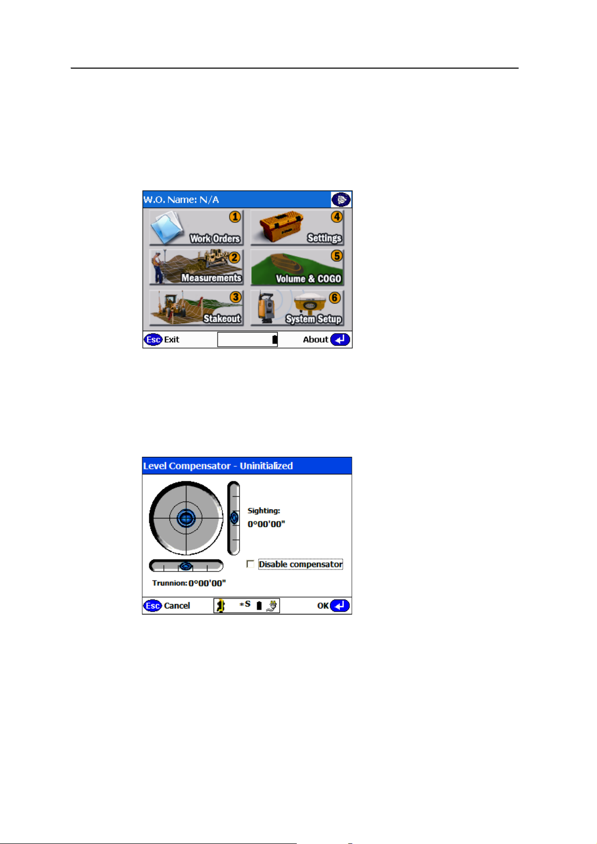
The SCS900 software starts and the main menu appears:
Connecting to a total station
When you start the SCS900 software, it automatically looks for a connection to the
total station through a cable connection (TSC2) or through a direct connection
(Trimble CU). When the connection is made, the Level Compensator dialog appears:
Note – If you use a Trimble CU controller in GPS mode and then attach it to a total station,
the controller will not automatically connect to the total station unless you are in Total
Station mode (select
controller in GPS mode, it cannot find the connection even if it is connected directly to a
total station.
System Setup / Switch to Total Station Setup). If you leave the
12 SCS900 Site Controller Software Total Station User Guide
Page 15

Connecting to a Total Station and Setting up the Controller 2
If you are using Bluetooth® wireless technology to connect to the total station (SPSx10,
SPS700, or SPSx30 only), you must first turn on the total station and enable Bluetooth
(using the face 2 display menu), and then manually force the connection to it.
If you are using a radio to connect to the total station, you need to manually force the
connection to it. For more information, see Chapter 10, Setting up the Total Station for
Robotic Operation.
To force either a radio or Bluetooth wireless connection:
1. Select
2. Select
3. Select either
System Setup. The System Setup Menu – Instrument appears.
Connect Instrument. The Connect Instrument menu appears.
Connect via radio or Connect via Bluetooth.
4. Follow the instructions that appear on the screen.
Leveling the total station
The compensator inside the total station provides dual-axis correction for any mislevel
of the instrument during operation, for a working range of up to 6' of arc. The display
enables you to level the total station accurately using the foot-screws on the tribrach.
To level the total station:
1. Align the front face of the total station with two tribrach foot-screws.
2. Adjust the horizontal bubble in the display using those same two foot screws.
3. Adjust the vertical bubble using the third foot screw.
4. Once level, tap
Note – You can disable the compensator, however, only do this in extreme working
conditions such as when working:
• in close proximity to a piling rig, vibratory compactor, or other source of extreme
ground vibration which would continuously affect the compensation effect on the
total station
OK.
• on a mobile platform where the level is continuously changing, but where all
measurements are needed in the reference frame of the platform itself, for example
on a marine vessel or oil platform
• in extremely windy conditions where wind buffet on the total station is significant,
and again would continuously affect the compensation of the total station.
If the compensator is switched off, the total station stops correcting for instrument
mislevel. In these situations, watch and adjust the level on a regular basis.
At this point, Trimble assumes that the total station is set up accurately over a known
point or that you have set it up in a convenient location, and will establish its position
using the arbitrary location method (also known as free station or resection). For more
information, see Setting up at an arbitrary location, page 43.
SCS900 Site Controller Software Total Station User Guide 13
Page 16
2 Connecting to a Total Station and Setting up the Controller
Correcting for atmospheric conditions
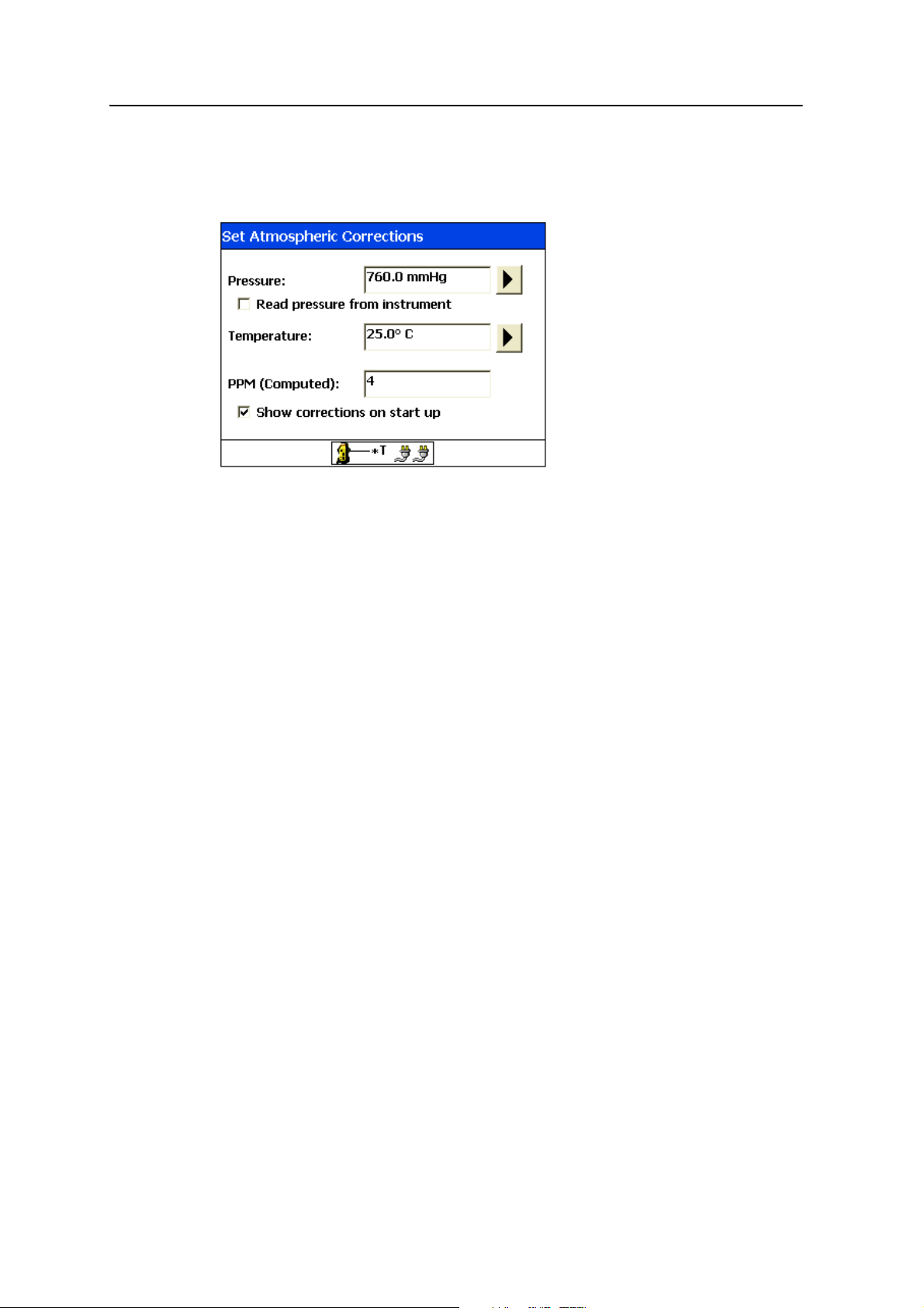
The following dialog appears, if the Show corrections on start up check box was left
selected during a previous operation:
B
Tip – Alternatively, open this dialog from the Instrument Functions menu (see page 133).
When measuring distances, the total station’s Electronic Distance Meter (EDM) is
affected by the temperature and pressure at which the instrument is being operated.
Accurate entry of the ambient air temperature and barometric pressure correctly
adjusts the EDM measurements for the PPM (parts per million) error associated with
this effect.
The Trimble SPS610, SPS700, SPS710, SPS730, and SPS930 total stations automatically
detect the pressure, but you have to enter the temperature. For high accuracy work or
long range measurements, you should measure the temperature using a thermometer.
For normal site work, estimating temperature or getting it from a weather forecast is
normally sufficient. You must also enter the pressure on the Trimble 5600 total station
and the Trimble ATS total station; it can be taken from a weather forecast or measured
with a barometer.
Note – When working at high altitudes, your barometric pressures will be considerably
lower than if you are operating at sea level, which can have a significant effect on the PPM
errors. Average daily changes in temperature have a far less impact on the PPM error and
if estimated to within a few degrees are adequate for the normal operating ranges of the
total station (<500 m, <1500 ft). When working at the maximum ranges of the total station
(5,000 m, 15,000 ft), use more accurate values, as the errors become more significant with
extended range of operation.
14 SCS900 Site Controller Software Total Station User Guide
Page 17
Connecting to a Total Station and Setting up the Controller 2
Selecting the external battery type
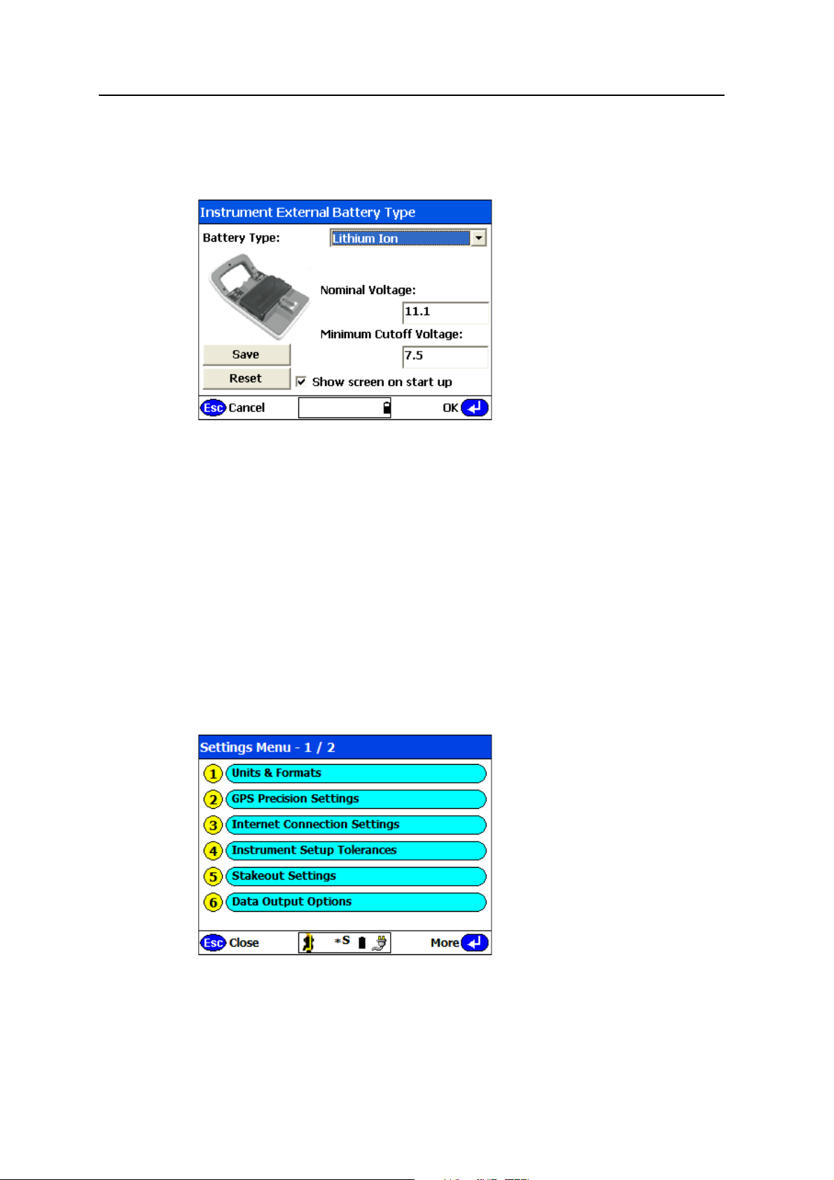
The Instrument External Battery Type dialog appears, if the Show screen on start up
check box was left selected during a previous operation:
B
Tip – Alternatively, open this dialog from the Instrument Functions menu (see page 133).
Select the type of external battery that is to be used by the SPSx10, SPS700, or SPSx30
total station. Enter its specifications to characterize the battery. Characterizing the
battery does two things:
• It protects the battery from the total station taking its voltage too low thereby
prohibiting damage
• It ensures that the total station can maximize the use of the battery assuring the
longest operational time from the battery
For more information, see page 134.
Setting up the controller
From the main menu, select Settings:
SCS900 Site Controller Software Total Station User Guide 15
Page 18
2 Connecting to a Total Station and Setting up the Controller
The settings that you should set up now are:
• Units & Formats
• Instrument Setup Tolerances
• Data Output Options
These settings will then be used in every site and every work order created and opened.
Units and Formats option
The first time that you use the SCS900 software, you need to set the units and data
formats correctly before you take a measurement or associate a design with a site. It is
important that you do this before you take a measurement or associate a design with
the site. All files that relate to a single site must be stored and operated with the same
units. Once a measurement has been taken, or a design has been selected, you cannot
change the units.
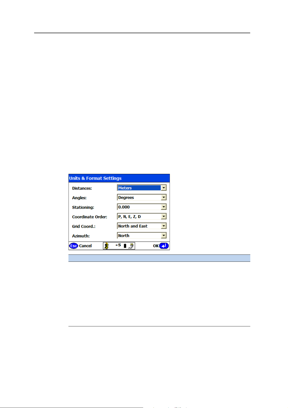
Set up the SCS900 software to operate in your units and formats of choice and to
operate in the correct coordinate system.
From the Settings menu, select
Field Description
Distances Distance units supported include Meters, US Survey Feet, and International
Feet. The distance units are applied to all imported data, computed
information, and measured positions.
Select the setting appropriate to your region of operation.
Angles Angle units can be measured in Degrees or Gons. The specified angle units
are applied to all computed and displayed angular information.
Select the setting appropriate to your region of operation.
Stationing Stationing (also known as chainage) formats currently supported include
0.000, 0+00.000, and 0+000.000. The selected stationing format is applied
to all measured, computed, and displayed station (chainage) values.
Select the setting appropriate to your region of operation.
Units & Formats:
16 SCS900 Site Controller Software Total Station User Guide
Page 19
Connecting to a Total Station and Setting up the Controller 2
Field Description
Coordinate
Order
Grid Coord Supported grid (Cartesian) coordinate systems include that where the axes
Azimuth Azimuth direction options currently include north or south. Azimuth
The order in which coordinate values will be interpreted within control
point and stakeout point files can be either P,N,E,Z,D or P,E,N,Z,D where:
P = Point Name or Number
N = Northing
E = Easting
Z = Elevation
D = Description or Point Code
The selected coordinate order dictates the way that those point files will be
read and used, and how coordinates will be entered, displayed, and
recorded by the software.
Note – Reading a control points or stakeout point file where the data items
are actually in a different order to that defined by this setting causes the
software to incorrectly use the values in the file.
of increasing positive coordinates extend north and east, and that where
they extend south and west. The Grid Coord field dictates the direction of
increasing coordinate values. In most regions, coordinates typically increase
to the north and east direction. However, in a few countries the coordinates
increase in a different direction, for example in South Africa, the
coordinates increase to the south and west.
Select the setting appropriate to your region of operation.
direction in most regions has its zero origin direction as true north.
However, in some countries the origin or zero direction is set to a different
direction, for example in South Africa, a zero azimuth is in the direction of
the south axis.
Select the setting appropriate to your region of operation.
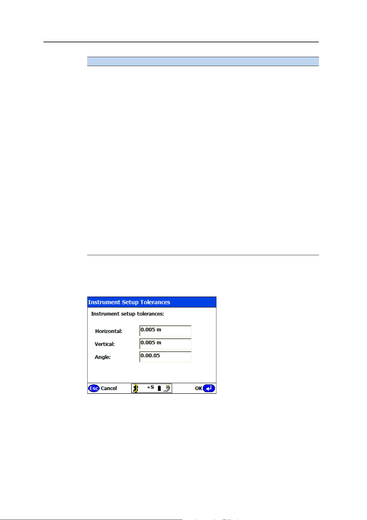
Instrument Setup Tolerances option
From the Settings menu, select Instrument Setup Tolerances:
When setting up the total station, and while measuring or staking points, the total
station checks the values measured against a set of entered tolerances for operation,
and notifies you if the measurements are in or out of tolerance.
SCS900 Site Controller Software Total Station User Guide 17
Page 20
2 Connecting to a Total Station and Setting up the Controller
Setting tolerances too low results in failure to generate appropriate warnings; setting
tolerances too high results in frequent warnings. You should ensure that the values
that you enter for the tolerances are:
• accurate enough for the work being carried out
• within the capabilities of the total station
For example, if stakeout has to be achieved to an accuracy of better than 5 mm (.016 ft),
do not set the stakeout or instrument setup tolerance to 15 mm (.049 ft). If the total
station in use has a horizontal angle accuracy of 5" arc, do not set the instrument setup
tolerance to 1" arc as this will never be achieved.
The following table shows the specified accuracy of the supported total stations:
Total station Horizontal angle Vertical angle Distance
5605 DR200+ 5” 5” 3 mm +/- 2 ppm
ATS 1” 1” 2 mm +/- 2 ppm
SPS610 5” 5” 2 mm +/- 2 ppm
SPS700 5” 2” 3 mm +/- 2 ppm
SPS710 3” 2” 3 mm +/- 2 ppm
SPS730 3” 2” 3 mm +/- 2 ppm
SPS930 1” 1” 3 mm +/- 2 ppm
Data Output Options
The last settings to consider are what data you want to store during operation and
then output on completion of a work order.
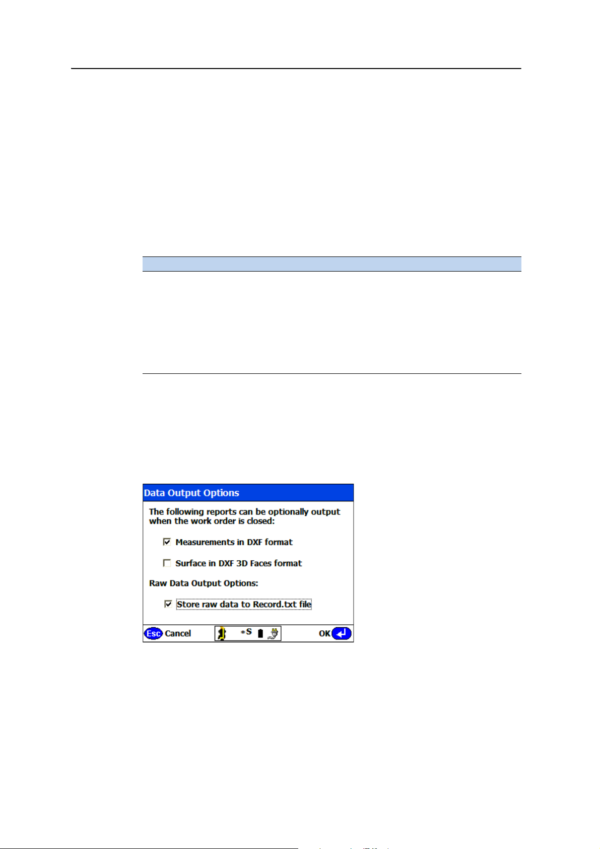
From the Settings menu, select
Data Output Options:
To record raw measurement data (HA VA SD) along with all computed positions etc,
select the Store raw data to Record.txt file check box. Raw data will be stored with each
measured or staked location.
18 SCS900 Site Controller Software Total Station User Guide
Page 21

Connecting to a Total Station and Setting up the Controller 2
To add a 3D Triangulated Irregular Network (TIN) surface model to the DXF CAD file
output, select the Surface in DXF 3D Faces format check box.
On completion of a work order, the software optionally creates a CAD compatible DXF
file of all the measurements and stakeout records taken during execution of the work
order. The Measurements in DXF format and the Surface in DXF 3D Faces format options
enable you to add the following output to the DXF file:
• measurements only (points, lines, areas, boundaries measured, and staked
locations)
• surface only (that is, the triangulated model of the surface)
• measurements and the surface
The resulting DXF file comprises a number of layers, depending on the options
selected. It includes the following:
• Surface-Data (measurements)
• Surface-Faces (3D TIN surface model)
• Surface-Boundary (outer boundary of the model)
• Survey-Data (site features i.e., non surface data)
• COGO (computed points)
• Staked-Points (as-staked locations)
SCS900 Site Controller Software Total Station User Guide 19
Page 22

2 Connecting to a Total Station and Setting up the Controller
20 SCS900 Site Controller Software Total Station User Guide
Page 23

CHAPTER
3
Creating a Site and a Work Order 3
In this chapter:
Organizing data
Creating a new work order and a
new site
Opening an existing work order
Completing a work order
All SCS900 operations are carried out on a
specific site. Work orders are associated with that
same site. Before you can begin work, you need to
create a work order or open an existing work
order.
A work order contains a record of every
measurement or stakeout operation completed.
Work orders also allow tasks to be monitored in
terms of progress towards completion, and allow
different types of tasks to have different settings
and tolerances. Work orders also record every
setting and change of setting made while you
work.
Many tasks such as setting up a new site, design,
or work order, and the settings or operational
parameters for those operations can be
established using the SCS900 software or the
SCS900 support utilities ( for example, the SCS
Data Manager, the Trimble Business Center
software, or the Terramodel
and then transferred to the controller.
Establishing these tasks and settings in the office
enables the supervisor to control and manage the
quality of all the operations.
®
Field Data Module)
SCS900 Site Controller Software Total Station User Guide 21
Page 24

3 Creating a Site and a Work Order
Organizing data
Data is organized by site. Within each site, data is further divided into designs and
work orders.
Sites
An SCS900 site is a project that contains records of all activities that a crew does on a
jobsite. The site contains the following:
• all settings and information that would be considered a requirement for the
execution of any type of task (known as a work order)
• a background map
• a control points file
• the GPS site calibration information
• a geoid model for GPS operations
• all software settings that would be considered applicable as the default settings
for any task executed on the project
Site information is available to all work orders carried out on the site.
Storage of sites
SCS900 sites are stored in the Trimble SCS900 Data folder or root folder.
• If you are using a controller that runs Windows
®
CE .NET (for example, the
TCU), then the root folder is \Disk\Trimble SCS900 Data.
• If you are using a controller that runs Windows Mobile
®
Pocket PC, ( for
example, the TSC2), then the root folder is \<StorageCard>\Trimble SCS900
Data.
• If you are running the SCS900 Tablet Edition on a laptop or tablet PC, then the
root folder is \Trimble Synchronizer Data\PC\Trimble SCS900 Data.
In this way, if you synchronize other SCS900 controllers with the tablet PC using
Trimble Office Synchronizer, they will be added as additional devices beneath the
\Trimble Synchronizer Data folder so their information can easily be seen and
reviewed using the SCS Data Manager.
Designs
A site can contain one or more designs. Each design contains all the information
relating to a specific aspect of the construction of the project, for example, original
ground, finished grade, utilities such as sewers, electrical, gas, water, pads, roads, and
other similar groupings. A single SCS900 design for example, can comprise a CAD
drawing, one or two surfaces or roadway models, and a stakeout point list.
22 SCS900 Site Controller Software Total Station User Guide
Page 25

Creating a Site and a Work Order 3
Information stored at this level includes foreground maps, stakeout data, and a design
surface or road model.
Work orders
A work order is a job or task (or a set of tasks) that needs to be carried out on a
particular site. The following are typical tasks:
• checking grade on a completed surface
• staking out a parking lot
• measuring a stockpile volume
• measuring a progress volume
The Trimble SCS900 Site Controller software is task-oriented. When you open a work
order, the software automatically retrieves the data that you need to complete that
work order.
A work order defines the site. It can also, but does not have to, reference:
• a design, which has the data needed to carry out the task
• an underlying surface design, which has any previously-measured, saved
surfaces that can be used for material thickness checking
For a material thickness check, only an underlying surface design is required.
For a grade check and material thickness check, a design and an underlying
surface design are required.
Two surfaces can be used to display cut/fill when using Location GPS with a poor
vertical precision. The cut/fill values are the difference between a recent topo survey of
the surface and the desired design surface.
A work order can also include basic written instructions to the operator that outline
the requirements for the task.
Tasks such as setting up the base station, carrying out a station establishment with a
total station, carrying out a measurement of the original ground levels for a site, and so
forth, do not require the work order to have a referenced design.
Tasks such as carrying out a grade check of a finished surface, carrying out any
stakeout operation, or displaying real-time cut and fill around the site require the work
order to have a referenced design.
There can be many work order subfolders within the main work orders folder. Each
work order subfolder contains:
• An initialization file called <Work Order Name>.ini that references the relevant
design files and define the settings for the work order.
• An Output folder that contains all data stored or output during the execution of
the work order. This includes the data collected in the field, computed by the
SCS900 software, or generated during field operations.
SCS900 Site Controller Software Total Station User Guide 23
Page 26

3 Creating a Site and a Work Order
The following files are continually updated and stored in the Output folder:
– <Work Order Name>-Record.txt – Contains a record of every point
measured or staked out, and includes station establishment and control
point measurement records.
– <Work Order Name>-Report.txt – Contains a record of every function
used and every result reported on-screen during the execution of a work
order. This is effectively a log file of activities and the results generated.
The following file is created when you complete a work order:
– <Work Order Name>-Measure.dxf
• An optional work order instruction file called <Work Order Name>.txt.
Global data
The following data is used by all sites:
• Lists of feature codes
• Lists of operator names
• Geoid files
Creating a new work order and a new site
Before you can set up the SCS900 software to use with a conventional system and
collect site measurements, you must create or open a work order. Every SCS900 field
operation requires a work order, or task-related folder, into which field results are
written.
You can create work orders in the following ways:
• In the office – Using the SCS Data Manager or the Terramodel Field Data
Module, you can assign it to a field crew and then use the Trimble Office
Synchronizer utility to transfer the work order to a controller. For information
about these utilities, refer to the SCS900 Site Controller Software Office Guide.
• In the field – Directly on the controller by the crew in the field, as and when
required, for example, to carry out a site measurement task.
24 SCS900 Site Controller Software Total Station User Guide
Page 27
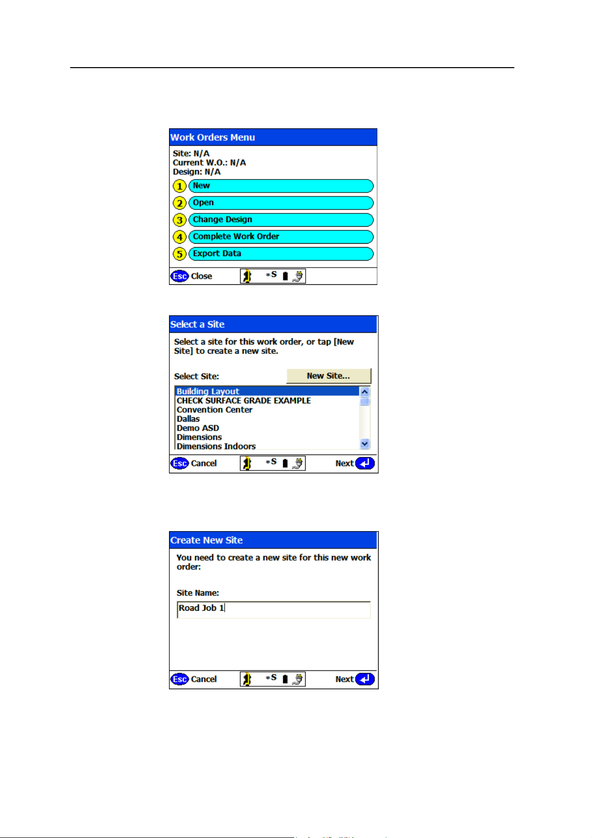
To create or open a work order in the field:
Creating a Site and a Work Order 3
1. From the main menu, select
2. To start a new work order on a new site, select
Work Orders:
New:
B
Tip – If you are working on a site that already exists, select the site from the list and then
tap Next. Then go to Step 7.
3. Tap New Site:
SCS900 Site Controller Software Total Station User Guide 25
Page 28
3 Creating a Site and a Work Order
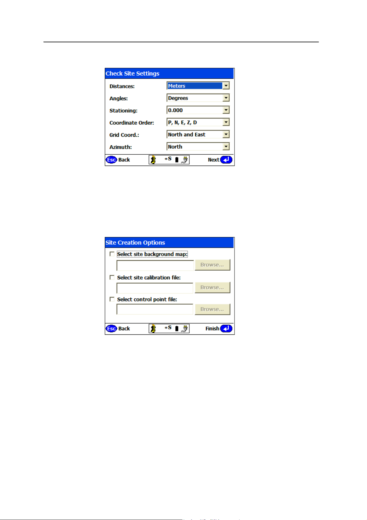
4. Enter the name of the site (for example, Road Job 2) and then tap Next:
5. Confirm or change the unit settings for the new site. These values default to the
ones that you have already set up (see page 16).
Note – Always set the distance units correctly before taking a measurement or associating
a design with the site. All files that relate to a single site must be stored and operated with
the same units. Once a measurement is taken, or a design is selected, you cannot change
the units.
6. Tap
Next:
For this example, the following items are not available: a site background map
(provides a reference map for the site in all work orders), a site calibration file
(used for GPS operations), or a control points file (needed to set up the total
station when known control points exist).
26 SCS900 Site Controller Software Total Station User Guide
Page 29
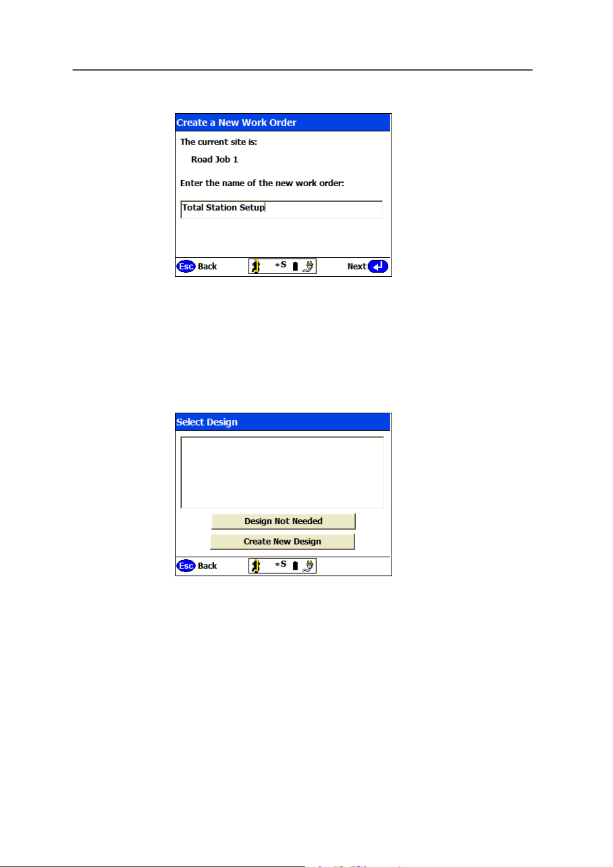
7. Tap Finish:
Creating a Site and a Work Order 3
B
8. Enter a name for the work order and then tap
Tip – Give work orders a meaningful name to make it easy to identify them when
multiple work orders are created for a particular project. If you are using the total station
only for machine control work, that is, no site measurement or stakeout operations, then
name the work order something like Daily Total Station Setups. If you are staking, for
example, a sewer line, then name the work order Stake Sewer Line. If relevant, you can
also add the date to the name of the work order so you know when the task was started,
for example Stake Sewer Line 120606.
The following dialog appears:
Next.
B
9. The dialog lists all designs associated with the opened site. At this stage, you
only want to establish the total station position and carry out a site calibration;
you do not have a design requirement (typically needed for stakeout or grade
checking operations). Select <No design needed> and then tap
software enables you to select a maximum of two design surfaces. Use the
Primary tab to select the main design surface and use the Underlying tab to
select the secondary design surface.
Tip – If you require only one design surface, select <No design needed> on the
Underlying tab.
SCS900 Site Controller Software Total Station User Guide 27
Finish. The
Page 30

3 Creating a Site and a Work Order
Note – With every task, the operator’s name is stored with the task as a part of the recorded
information.
The work order is now open on the new site.
Opening an existing work order
To open a work order that was created in the office, or previously created in the field:
1. From the main menu, tap
The Select a Work Order dialog appears. It lists all the work orders for the current
site. To choose a work order from a different site, tap
2. Select the work order from the list and then tap
=.
3. Review the information that appears on the screen. Check the site name, the
work order name, and any design(s) associated with the work order. Tap
Confirm or press = to continue.
Completing a work order
On completion, the work order contains the following:
• Reference to the site that it was carried out on.
• Reference to the design data that was used in completing the task (surface, CAD
drawings, road models, or stakeout point data).
• A record of all the settings and tolerances that were used in the execution of the
task.
• A record of all measurements made, all in-field reports generated, and a log of all
activities carried out to complete the task.
Work Orders / Open.
Change Site.
Next or press the Enter key
• Optionally, an output CAD (.dxf ) file containing all of the measured, COGO, and
as-staked information. It may also contain a 3D faces model for the surface
created from the measurements made.
On completion, the results from a work order can be reviewed and analyzed using the
SCS Report Utility, viewed in the SCS Data Manager, or imported into the Trimble
Business Center software – HCE software, the Terramodel software or the SiteVision
Office software for more in-depth analysis.
28 SCS900 Site Controller Software Total Station User Guide
®
Page 31
CHAPTER
4
Main Menu Structure 4
In this chapter:
Work Orders menu
Measurement menu
Stakeout menu
Settings menu
Volume & COGO menu
System Setup menu
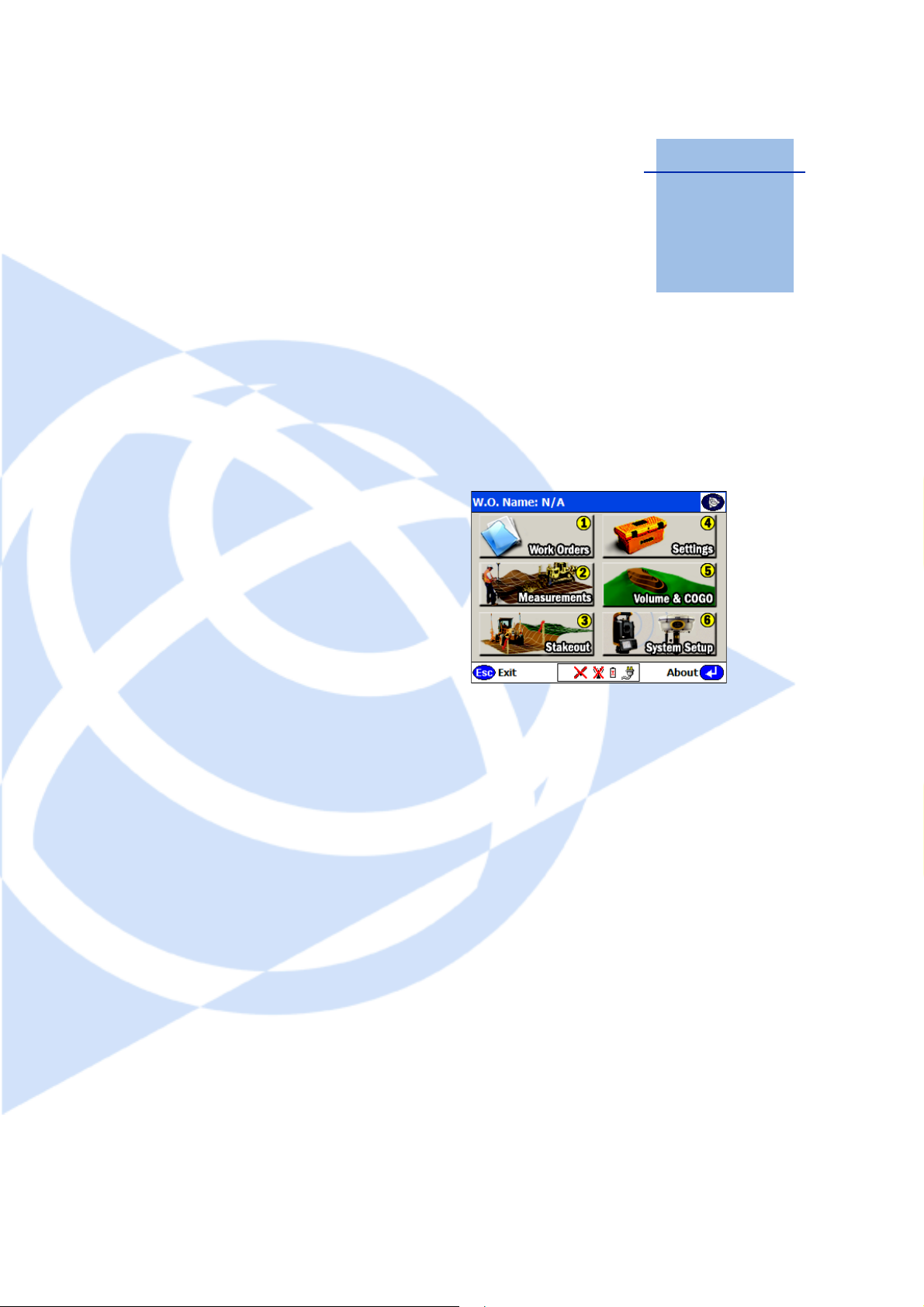
The SCS900 software is a menu-driven system,
for ease of use and learning. When you open the
software, the main menu appears, providing
access to six submenus:
Once set up, whether being used by GPS or by a
total station, there are two main functions:
1. Measurements – This function enables you
to measure and record the location, or
as-built location, of features or surfaces or
objects on a project, or to collect
information that allows you to create a
surface model, from which you can make
volume computations, and grade or material
thickness checks.
2. Stakeout – This function enables you to
stake or relocate any aspect of the site
including point features (such as manholes),
line features (such as curbs, foundations, and
footings), planar surface features (such as
pads), or surfaces (such as site terrain
models, side slopes and catch points, or road
surface models).
SCS900 Site Controller Software Total Station User Guide 29
Page 32
4 Main Menu Structure
Work Orders menu
The Work Orders menu contains the tools to create, open, and complete work orders.
The menu also provides the capability to change the design referenced by the current
work order, and output new design data from the current work order, for example, the
original ground topographic measurements.
This menu also provides the ability to export measured information or selected design
information to a CompactFlash card for use in the GCS900 Grade Control System or
the SiteVision
Command Description
New Create a new work order in the field as required for a
Open Open an existing work order. This can be:
Change Design Select a different design, which provides different information
Complete Work Order Complete the currently open work order and write the
Export/Import Data (TCU
and TSC2 controllers)
Save surface as design Write the surface data that was measured in the field, to a new
®
machine control systems.
requested task, for which no work order has been provided.
The SCS900 software creates a new work order that references
a specific site and design.
• a new work order, created by the supervisor, which you are
to carry out
• an in-progress work order, which you need to retrieve data
from or add data to
• a previously completed work order, which you need to
reopen to retrieve information or to add information to
to that currently loaded, as a result of a change in the design
for the project, or a request to do something within the
current work order that requires different design data.
Work-Order Measure.dxf file.
Write the surface data that was measured in the field to a new
design surface; export the site calibration file to a
CompactFlash card; export a design to a CompactFlash card for
use with the GCS900 Grade Control System, save site
calibration data to a memory card; and send or receive files
from “intelligent” emails.
design surface.
30 SCS900 Site Controller Software Total Station User Guide
Page 33

Measurement menu
The Measurement menu contains all site measurement functions. With the dedicated
functions, you can check grades and material thickness, take topographic
measurements to create surface models ( for example, volume computations), take site
feature measurements to record the location of non-surface features, and provide
real-time cut/fill information against a selected design model.
Before you enter this menu, set up the system using the System Setup menu. If you do
not, when you select an option in this menu, the software automatically puts you
through either the station establishment process (for a total station) or the rover setup
(for GPS).
Command Description
Check Surface Grade Check the grade of a surface against a selected design.This
Check Grade of Roadway
Check Material Thickness Check the thickness of laid materials against the specified
Measure Surface Measure a surface: points, break-lines, volume boundaries, and
Measure Site Features Measure site features not used in the creation of a surface.
Display Real-Time Cut/Fill Check current cut and fill at any location on the project against
Intelligent Scanning Scanning options for use with total stations, specifically for
Main Menu Structure 4
option is available only when the current design is not a road.
Specify a high or low tolerance for the finished grade and
check whether or not the grading operations have achieved
tolerance.
This option is available only when the current design is a road.
thickness.
the site boundary.
the original ground, finished design, or any other surface.
scanning stockpiles or recording profile lines of objects like
quarry walls or high walls.
For information about how to use the site measurement functions, refer to the SCS900
Site Controller Software Measurements User Guide.
SCS900 Site Controller Software Total Station User Guide 31
Page 34
4 Main Menu Structure
Stakeout menu
The Stakeout menu contains all SCS900 stakeout functions including staking points,
lines and alignments, planes, surfaces, side slopes, catch points, and road features.
Before you enter this menu, set up the system using the System Setup menu. If you do
not, when you select an option in this menu, the software automatically puts you
through either the station establishment process (for a total station) or the rover setup
(for GPS).
Command Description
Point Stake individual point data. The software guides you directly to
Line Stake lines and alignments or offsets to lines using station and
Side Slope & Catch Point Stake an earthwork operation that involves a tie to the current
Plane Create and stake out a level plane, a sloping plane, or a 3-point
Surface Stake out from a design surface. The software guides you
Road Stake roadway features, sideslopes, and catch points or any
Enter/Edit Stakeout Points Add, edit, or delete any stakeout points that are in the current
the point.
offset methods. The software guides you directly to the line.
ground surface.
plane. The software guides you directly to points on the plane.
directly to points on the surface.
This option is available only when the SCS900 road module is
not installed.
point on the surface.
This option is available only when the SCS900 road module is
installed.
design.
For information about how to use the site stakeout functions, refer to the SCS900 Site
Controller Software Stakeout Guide, or if you have the Road module installed, refer to
the SCS900 Site Controller Software Road and Side Slope Stakeout User Guide.
32 SCS900 Site Controller Software Total Station User Guide
Page 35
Settings menu
The Settings menu contains all the SCS900 system settings that control the units of
measurement, how the software operates, and what tolerances the software will use for
different functions during operation.
The settings provide control over Internet connectivity for VRS or remote base station
GPS operations.
The settings also control what data is recorded during operation and then exported
when a work order is complete.
Command Description
Page 1 of 2:
Units & Formats Specify the measurement units and the order of coordinates.
GPS Precision Settings Specify GPS measurement and site calibration tolerances.
Internet & VRS Settings Configure your Internet connection for use with “intelligent”
Instrument Setup &
Adjustment
Stakeout Settings Specify stakeout methods to be used, stake writing
Data Output Options Specify .dxf file output options (surface measurements and/or
Page 2 of 2:
COM Port Data Output
Option
Radio Baud Rate Change the receiver to radio baud rate for third-party and
Main Menu Structure 4
email functions, a VRS system, or create a new connection with
the New Connection wizard.
Specify horizontal, vertical, and angle setup tolerances and the
type of corrections to apply to the measured distance.
information, stakeout tolerances, and auto-aim controls for use
with a total station. Select map view options.
3D faces). Specify whether or not raw data will be output with
each record.
Enable the controller to output the instrument measurement
data through a COM port.
Trimble PDL 450 radios.
SCS900 Site Controller Software Total Station User Guide 33
Page 36
4 Main Menu Structure
Volume & COGO menu
The Volume & COGO menu contains a number of calculation (area, distance, bearing,
slope) and point generation functions (free point, offset points, radius point) that can
be used to generate points for stakeout operation from CAD data in the currently
loaded design.
The menu provides access to the contour generation function, which you can use to
review a measured surface before you use the Compute Volume option, to determine
stockpile or progress volumes. The menu also provides access to review and edit
functions for editing breaklines and deleting points or lines to resolve surface
modelling problems.
Command Description
Review & Edit Surface View or delete point and lines, add breaklines and boundaries,
Review Design Features Calculate volumes based on the design data, and calculate
Compute Distance & Area Compute areas, distances, and angles from measured or
Create Stakeout Points Create points by a variety of methods including free point,
Create/Edit Road Data Enter a roadway and perform COGO functions based on a road.
contour surface and calculate surface volumes (stockpiles) or
periodic progress volumes.
distances and areas.
stakeout data.
radius, and offset to a line. Free points can be created by
tapping the screen or entering coordinates.
This option is available only when the SCS900 road module is
installed.
34 SCS900 Site Controller Software Total Station User Guide
Page 37
System Setup menu
The System Setup menu contains the control and system setup functions for GPS or
total station operation:
• For total stations, use the menu to connect the instrument and carry out station
establishment to establish the position and orientation of the instrument. The
menu provides access to all total station control functions and calibration
procedures.
• For GPS, use the menu to start the base station, start the rover receiver, and then
carry out the site calibration process.
General functions include being able to enter and edit control point information,
measure new control points for the project, and recheck the system setup on a control
point.
The menu also provides the ability to switch between GPS and total station operations.
Main Menu Structure 4
Command Description
GPS
Set up Base Set up and start a Precision GPS base station.
Set up Rover Set up and start a GPS rover.
Calibrate Site Perform or resume a single-point, two-point, or multi-point
site calibration.
Recheck System Setup Check an existing site calibration on a known control point.
Enter/Measure Control
Points
Edit and enter control point coordinates.
Switch to Total Station Setup Access the Total Station System Setup menu.
Total Station
Connect Instrument Connect to the total station using a radio for robotic
operation or using Bluetooth
Servo, Autolock, or Reflectorless operation.
®
wireless technology for
Set up Total Station Position Set up the total station and establish its position and
orientation on the site using the known point or arbitrary
location (also known as free station or resection)
methods.
Instrument Functions Menu Provides access to all total station specific functions and
settings in addition to calibration procedures for angle
collimation, tilt axis, and tracker collimation errors.
Recheck System Setup Check the current instrument setup on a known point
location.
Enter/Measure Control Points Edit and enter control point coordinates; measure new
control points.
Switch to GPS System Setup Access the GPS System Setup menu.
SCS900 Site Controller Software Total Station User Guide 35
Page 38

4 Main Menu Structure
36 SCS900 Site Controller Software Total Station User Guide
Page 39

CHAPTER
5
Setting up Control Points 5
In this chapter:
Types of control points
Entering control point
coordinates
A control point is a location on site that is clearly
and permanently marked with a peg, nail, target,
or other permanent feature. Typically, it is in a
location that is unlikely to be disturbed or
destroyed. A qualified surveyor should establish
the known coordinates of a control point.
Each day when you set up the total station, you
will do one of the following:
• Set up over a known control point and
observe to one or more known control
points to establish the position, elevation,
and orientation of the instrument in
relation to the site coordinate system.
• Set up in a convenient but arbitrary
location and observe to two or more
known control points to establish the
position, elevation, and orientation of the
instrument in relation to the site
coordinate system.
Before you establish the total station’s position
and orientation on the project in order to carry
out a site calibration, you first need some control
points and their coordinate values stored in the
control points file for the site.
Control points are also required when you
recheck the system setup. For more information,
see Chapter 11, Rechecking the System Setup.
SCS900 Site Controller Software Total Station User Guide 37
Page 40
5 Setting up Control Points
Types of control points
The control point file is available every time you open any work order on a site. Control
points can be one of the following:
• 1D – Elevation only ( for example, a benchmark)
• 2D – Horizontal position only
• 3D – Horizontal position and elevation
Note – A 1D point appears only in the control point list and is not shown in the graphics of
the map view because its position is not known. A 2D or 3D point appears in the control
point list and in the graphics of the map view. A control point is marked with a black
triangle and you can control its visibility in the map by using the Map Display options.
Entering control point coordinates
After you create a new site, add the control point coordinates to a control points file.
To do t h is:
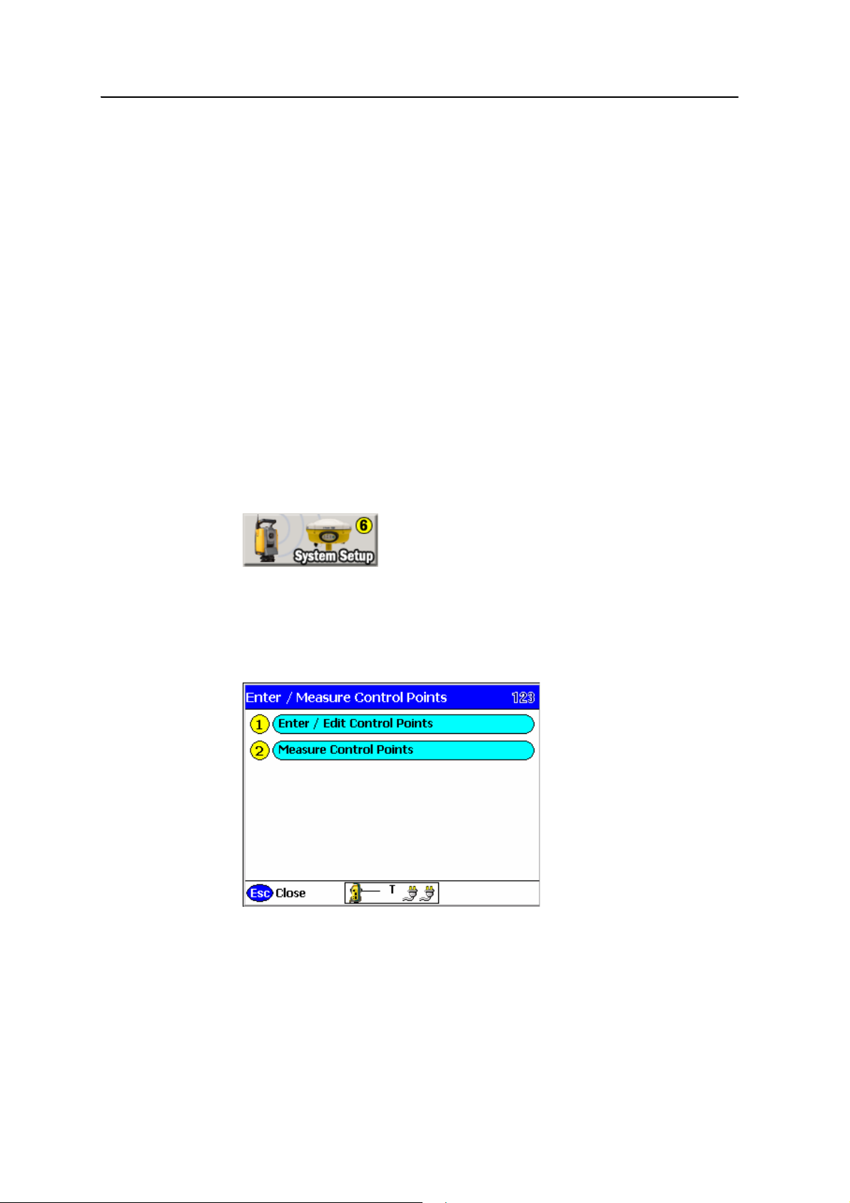
1. From the main menu, select
System Setup:
Note – If your System Setup Menu does not look the same as that shown above, you are
currently in GPS mode. To change to Total Station mode, select
Switch to Total Station
Setup.
Select Enter / Measure Control Points:
2.
At this stage, you should have a list of control points for the project. Control
points are normally marked on the plans or provided as a list by the project
surveyor.
38 SCS900 Site Controller Software Total Station User Guide
Page 41
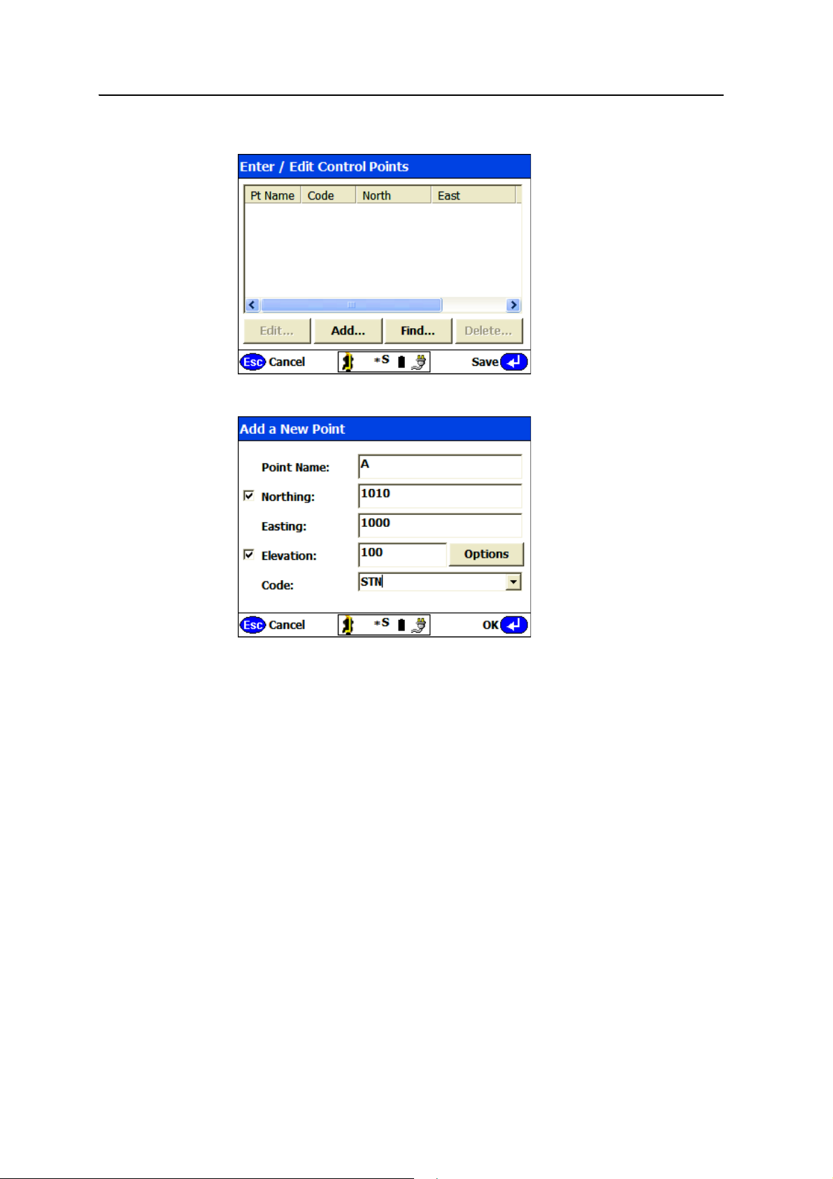
3. Select Enter / Edit Control Points:
Setting up Control Points 5
4. Tap
Add:
5. In the Add a New Point dialog, do the following:
a. Enter the control point name (which might commonly be a point number):
– For 1D points, select the Elevation check box and then enter the
elevation for the point.
– For 2D points, select the Northing check box and then enter the
northing and easting for the point.
– For 3D points, select both check boxes and then enter the northing,
easting, and elevation for the point.
b. Enter a code to identify what type of point it is, for example, Nail, Peg,
Ta rg e t .
c. Once you finish entering the data, tap
OK.
6. Repeat this process for all the control points provided. Once all points are
entered, tap
Save.
SCS900 Site Controller Software Total Station User Guide 39
Page 42

5 Setting up Control Points
The control points that you entered are added to a file called Control.csv, which is
stored in your Site folder. These coordinate points are always available on this site. You
can add more control points at any time, or measure new control points (see ) as
required.
You can also create the control point file in the office and then transfer it to the
controller.
40 SCS900 Site Controller Software Total Station User Guide
Page 43

CHAPTER
6
Establishing the Position and Orientation of the Total Station on the Jobsite (Station Establishment)
In this chapter:
Setting up at an arbitrary location
Setting up on a known point
Reading station setup data from
the total station
Completing a station
establishment where the height
of the setup point has not been
determined
The total station position and orientation is
necessary if the instrument is to be used for site
measurement, stakeout, or machine control
operations where the positions computed are
related to a site coordinate system.
There are two methods of establishing the
position and orientation of the total station:
• Arbitrary location (also known as free
station or resection)
• Known point
Once the station has been established, the total
station can be used for measurement, stakeout,
or machine control operations.
6
SCS900 Site Controller Software Total Station User Guide 41
Page 44
6 Establishing the Position and Orientation of the Total Station on the Jobsite (Station Establishment)
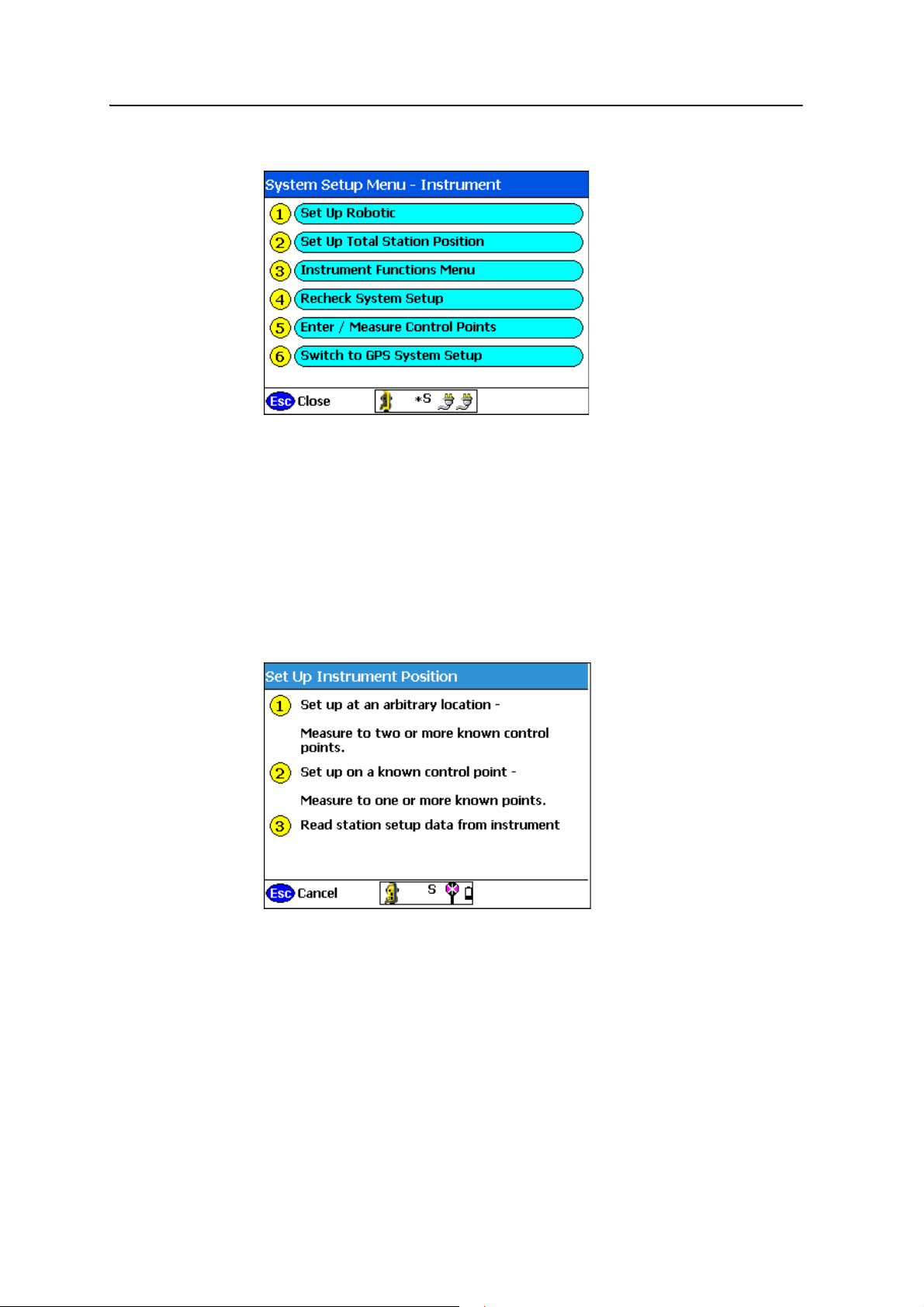
1. From the main menu, select System Setup. The following menu appears:
Note – If you have not established the position of the total station and you select a
measurement or stakeout function, the software automatically forces you into this process
when connected to a total station.
Note – If you have not entered any control point data for the site, the station establishment
process will only allow you to set up at a manually entered coordinate location and
orientation of the angle system to 0.0000 in a chosen direction. This method is acceptable
only if you are measuring a new site that has not been measured before and provided that
you are not trying to measure or stake anything from a loaded design. In most cases, you
should have control points available.
2. Select
Set Up Total Station Position. The following menu appears:
42 SCS900 Site Controller Software Total Station User Guide
Page 45
Establishing the Position and Orientation of the Total Station on the Jobsite (Station Establishment) 6
Setting up at an arbitrary location
The arbitrary location setup allows you to set up the total station at a location that is
convenient for the operation to be carried out (and not over a known point). It
measures the angle and distance to two or more known points to determine the total
station’s position and orientation.
To set up a total station at an arbitrary location:
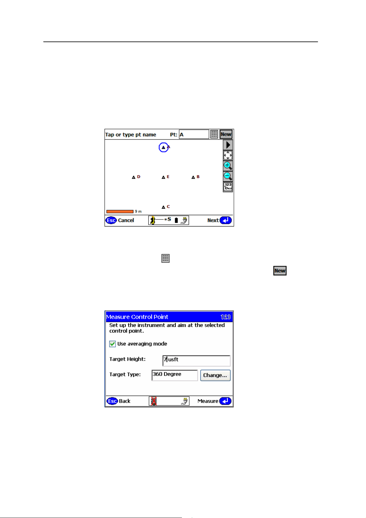
1. Select
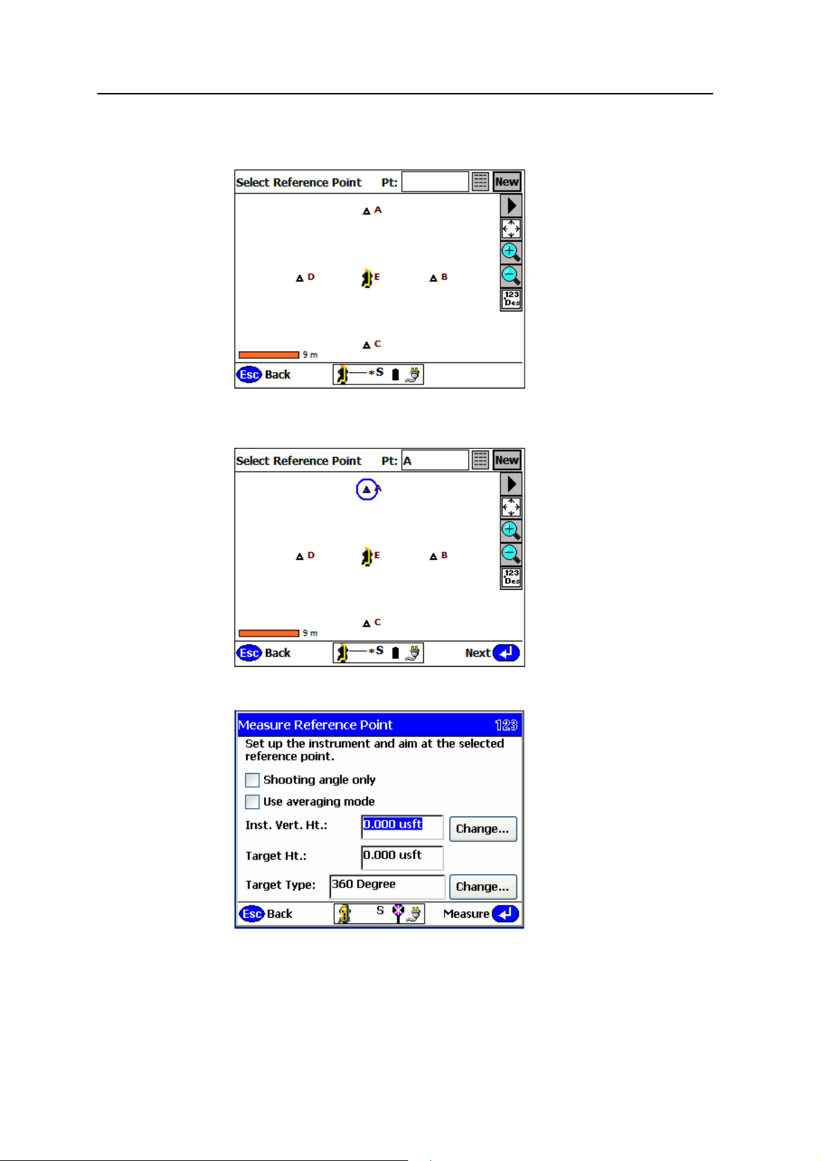
Set up at an arbitrary location. The map view appears:
2. Pick the first point using one of the following methods:
– tap the point (marked with a triangle)
– tap the list icon and then select the point from the list that appears
– if you need to add or edit a control point at this stage, tap and then
enter or edit the control point (see Step 2 on page 39)
When you select the point, it is highlighted with a blue circle as shown.
3. Tap
Next. The Measure Control Point dialog appears:
SCS900 Site Controller Software Total Station User Guide 43
Page 46
6 Establishing the Position and Orientation of the Total Station on the Jobsite (Station Establishment)
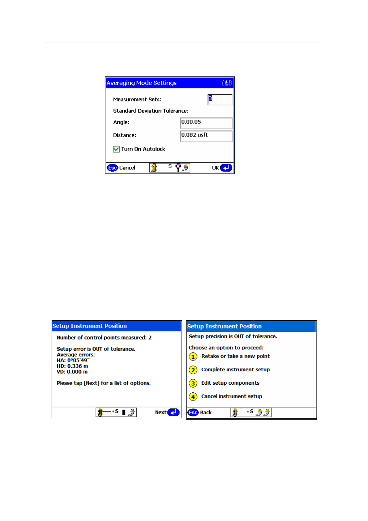
4. Select the Use averaging mode check box to make multiple observations to the
target in face 1 and face 2 and then tap
Measure:
5. In the Measurement Sets field, enter a value for how many measurement sets you
want to make. For example, entering
3 results in three measurements in face 1
and three measurements in face 2. Set the standard deviation tolerance for the
Angle and Distance fields. Select the Turn On Autolock check box to use the
Tracker for measurements in both faces. Leaving this box unselected means you
need to manually sight the instrument for all rounds in both faces. Tap
OK.
6. Enter the target height and target type for the point being measured. Point the
total station at the target.
7. Tap
Measure to measure the first control point. On completion of the
measurement, the software shows you that one point has been measured and
the precisions of that measurement. The blue circle changes to a green circle.
8. Repeat Step 2 through Step 7 to select and measure a second control point.
Once you have measured two points, you have a solution and at least some
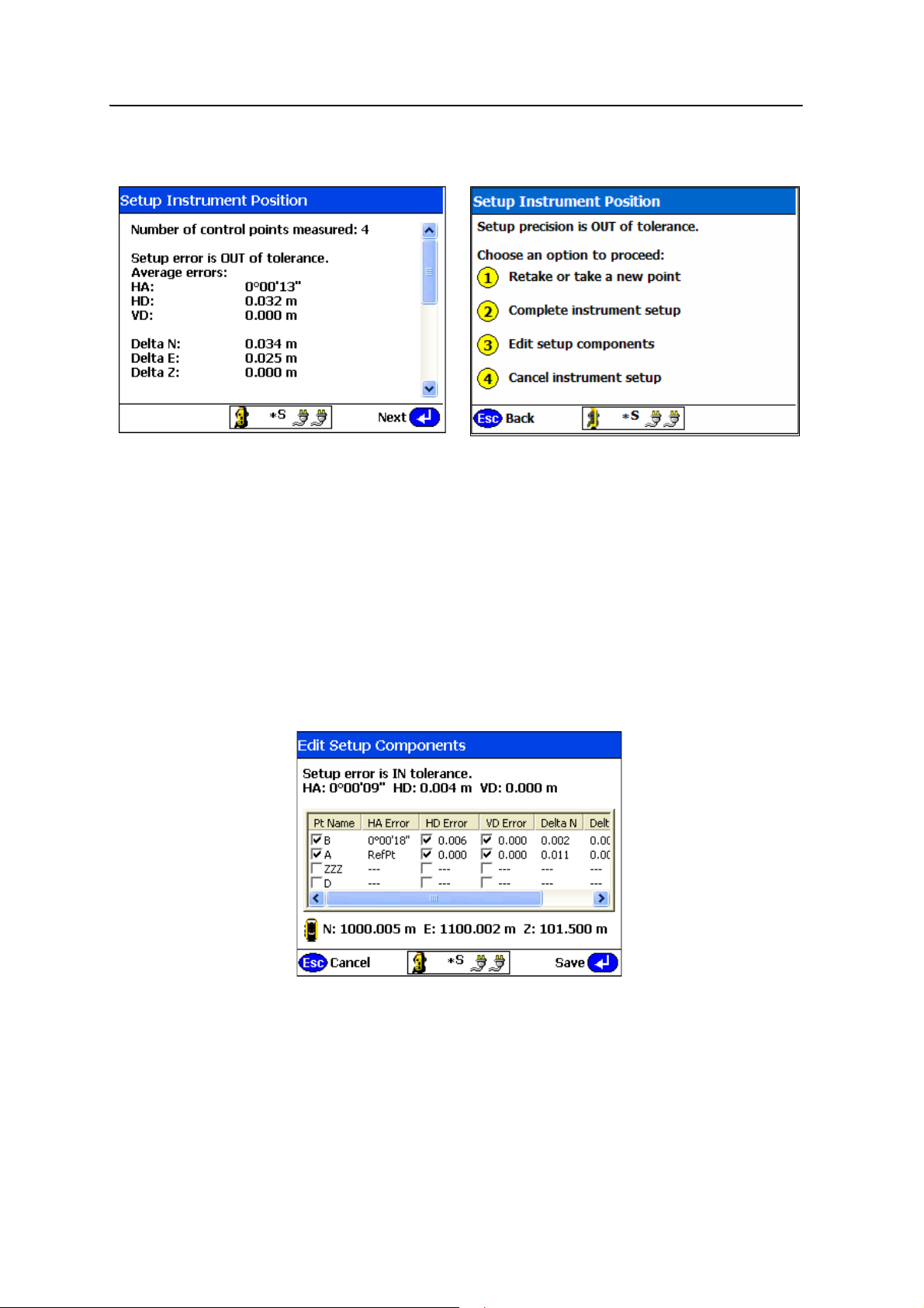
redundancy of information. At this point, you are informed if you are in or out of
tolerance, based on the settings entered earlier for total station instrument use:
44 SCS900 Site Controller Software Total Station User Guide
Page 47

Establishing the Position and Orientation of the Total Station on the Jobsite (Station Establishment) 6
9. Select from one of the following options:
Option Description
If the setup is OUT of tolerance
Retake or take a new point Allows you to measure another point or remeasure a
point, if for example, the measurements to date are
out of tolerance and you suspect that you have
measured the wrong point or measured incorrectly.
Complete instrument setup Allows you to accept a failed tolerance if it is "close
enough" for what you are doing. This overrides the
tolerance setting for the system for this specific setup.
Edit setup components Allows you to view all the measured points, and to
review the errors in horizontal and vertical
components for each point. The most suspect
observation is highlighted, and allows you to select,
deselect, or reselect components for use in the
position computation.
Cancel instrument setup You can cancel the total station setup and restart the
station establishment process or move to another
location and try again.
If the setup is IN tolerance
Retake or take a new point Allows you to measure another point or remeasure a
point, if for example, the setup is within the tolerance
specified, however you think the precision could be
improved by eliminating or remeasuring a point or
point component.
Complete instrument setup You can complete the station establishment process
and store the computed station position and
orientation, and then move on with measurement or
staking operations.
Edit the setup components Allows you to view all the measured points, and to
review the errors in horizontal and vertical
components for each point. The most suspect
observation is highlighted, and allows you to select,
deselect, or reselect components for use in the
position computation.
Cancel instrument setup You can cancel the total station setup and restart the
station establishment process or move to another
location and try again.
SCS900 Site Controller Software Total Station User Guide 45
Page 48
6 Establishing the Position and Orientation of the Total Station on the Jobsite (Station Establishment)
As each point is measured, the software recomputes and displays the error
analysis, providing the same options:
Unless there has been a gross error, for example, observing the wrong point,
Trimble recommends that you measure as many points as you can before you
try to resolve any out of tolerance issues. The only exception is if you are moving
long distances between points, and you believe that you should remeasure a
point before moving to the next one because it may be suspect.
10. If the computed position is in tolerance on completion of all point
measurements, then you have achieved the set instrument setup tolerance (see
page 17). Do one of the following:
– Select Complete instrument setup
– If you feel that you can improve the accuracy of the computed location by
manipulating some of the measured points, select
Edit Setup
Components. The following dialog appears:
This screen shows all the measured control points and the computed
errors associated with each point.
46 SCS900 Site Controller Software Total Station User Guide
Page 49
Establishing the Position and Orientation of the Total Station on the Jobsite (Station Establishment) 6
a. Enable or disable a complete point, or just the horizontal distance or
the vertical distance component to see what effect it has on the
solution.
b. When you are satisfied with the solution, tap
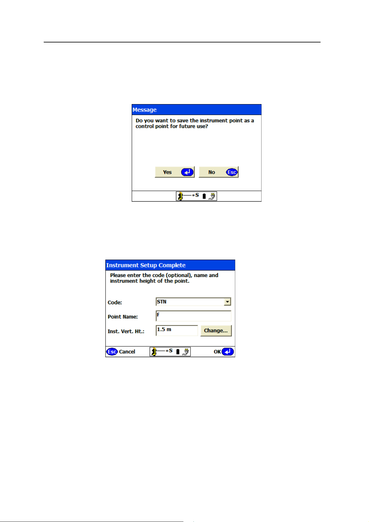
message appears:
11. Tap
Yes to save the computed position as a new control point in the control
point file.
Note – If you tap
No, the point is not stored in the control point file, and is not available to
you for later use.
The following dialog appears:
Save. The following
B
12. Enter the code, point name, and the instrument height, so that the software can
compute the true ground elevation of the point before storing it in the control
point file.
Tip – When using an SPSx10, SPS700, or SPSx30 total station, enter the instrument height
either as a vertical height to the upper marking (at the telescope height) or as a slope
height to the lower marking near the base of the total station on the side cover (easier to
measure). To change how the total station height is measured, click Change. The
software then computes the vertical height.
13. Tap OK. You are returned to the System Setup menu.
SCS900 Site Controller Software Total Station User Guide 47
Page 50
6 Establishing the Position and Orientation of the Total Station on the Jobsite (Station Establishment)
If you are using an ATS or SPSx30 total station, you can proceed with site
measurements or continue the setup for machine control (see Chapter 7, Setting Up an
ATS or SPSx30 Total Station for Machine Control).
Setting up on a known point
This allows you to set up the total station over a known control point location and
then measure to one or more reference control points to establish its position and
orientation on the jobsite. In most cases, a single reference control point may be all
that is required. In other cases, where the accuracy of the work is higher, measuring
more than one reference control point can provide better control over the orientation
of the total station and a further check that the control point at the total station
position or any of the measured reference control point locations has not moved.
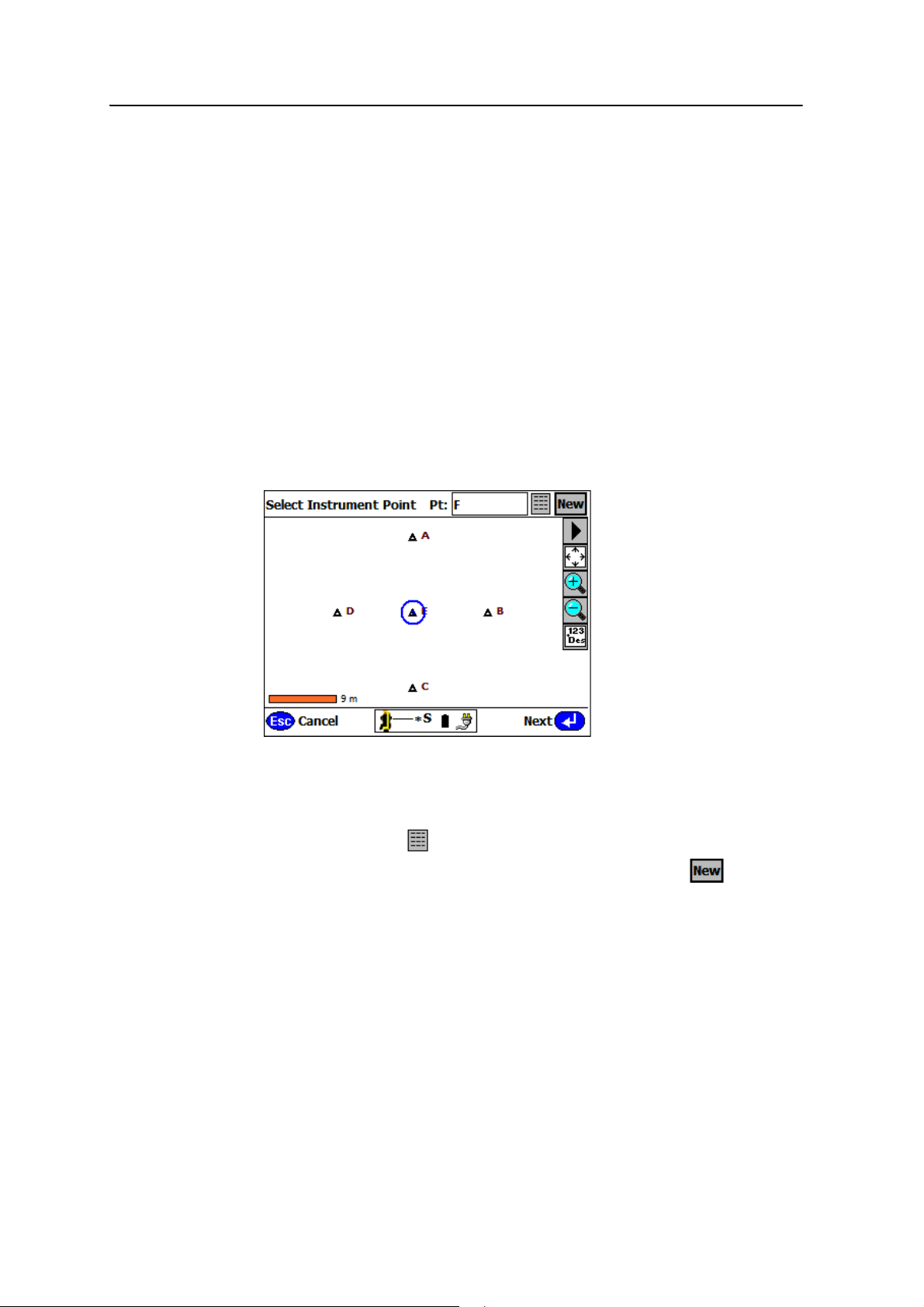
To set up a total station on a known point:
1. Select
Set up on a known control point. The map view appears:
2. From the map view, select the control point over which you are set up. Pick the
point using one of the following methods:
– tap the point (marked with a triangle)
– tap the list icon and then select the point from the list that appears
– if you need to add or edit a control point at this stage, tap and then
enter or edit the control point (see Step 2 on page 39)
When you select the point, it is highlighted with a blue circle as shown above.
48 SCS900 Site Controller Software Total Station User Guide
Page 51
Establishing the Position and Orientation of the Total Station on the Jobsite (Station Establishment) 6
3. Tap Next. The instrument icon appears at the selected location in the map,
indicating that it is the instrument setup point:
4. Select the first reference control point to be measured in the same way. The
reference control point is now highlighted with a blue circle:
5. Tap
Next. The following dialog appears:
6. Select the Use averaging mode check box to make multiple observations of the
reference point in face 1 and face 2.
SCS900 Site Controller Software Total Station User Guide 49
Page 52
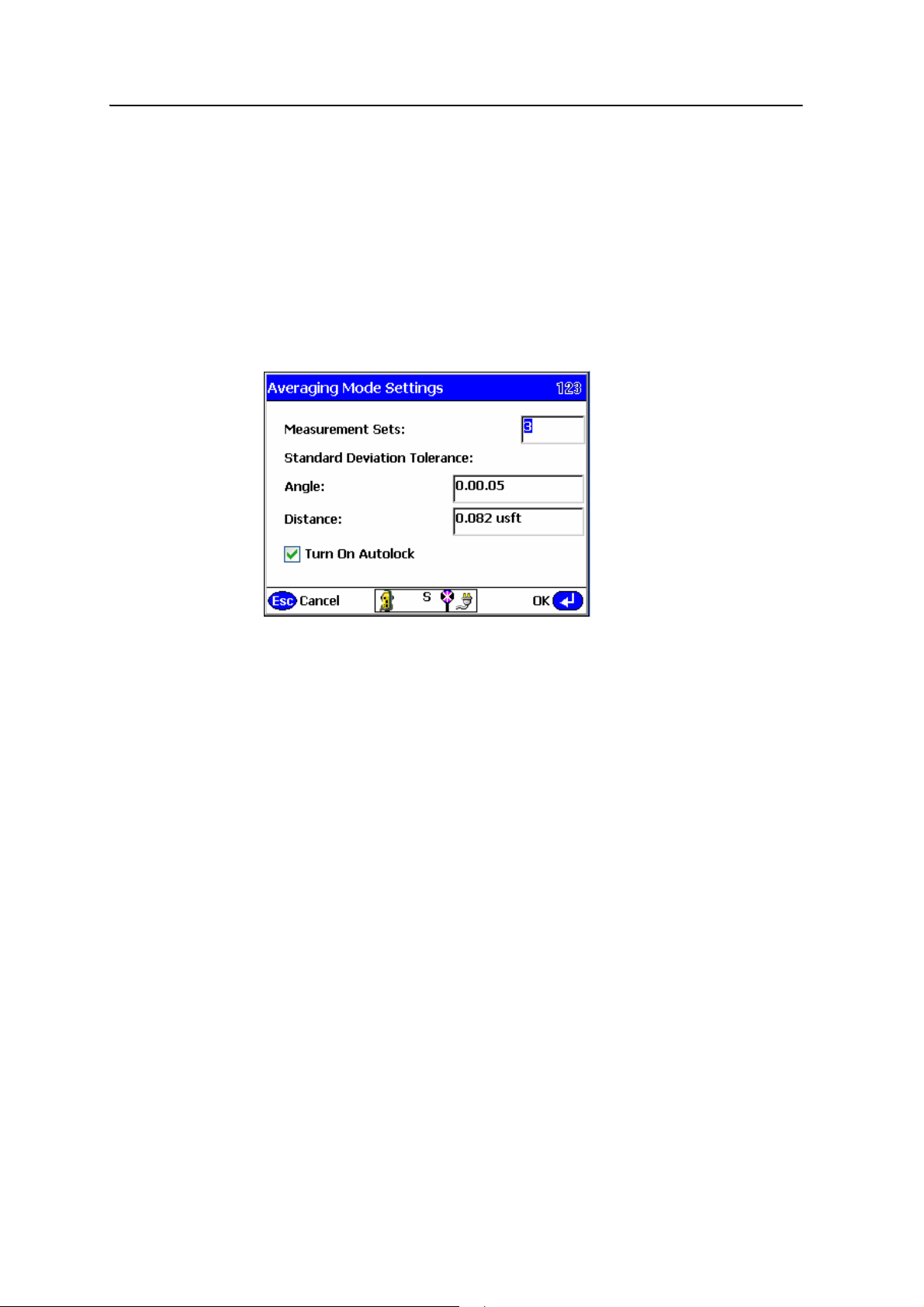
6 Establishing the Position and Orientation of the Total Station on the Jobsite (Station Establishment)
7. Enter the instrument height and the target height and then select the type of
target that will be used at the reference control point location.
If you intend to measure more than one reference control point, you should
measure all points (but you are not forced to) using a complete angle and
distance. If you only want to orientate the total station to any of the reference
control points and not measure the distance to it, before you take the
measurement select the Shooting angle only check box. The shooting angle only
function measures a horizontal and vertical angle to the reference point only.
8. Tap
Measure. If the Use averaging mode check box is selected, the following
dialog appears:
9. In the Measurement Sets field, enter a value for how many measurement sets you
want to make. For example, entering
3 results in three measurements in face 1
and three measurements in face 2. Set the standard deviation tolerance for the
Angle and Distance fields. Select the Turn On Autolock check box to use the
Tracker for measurements in both faces. Leaving this box unselected means you
need to manually sight the instrument for all rounds in both faces. Tap
OK.
Unlike the arbitrary location method, once you measure a single reference
control point, the information shown below appears on the screen. You can
follow similar steps to those used in the arbitrary location method of station
establishment.
B
Tip – To set the instrument’s angle measurement system orientation to a value other than
0.0000, add two control points to the control point file that will generate the required
orientation when used for a known point establishment. When using the known point
method, select the Shooting angle only check box since you will not have a real control
point to use as a reference. For example, to set a reference angle of 45.0000 (50.0000 gon)
enter two coordinate points, the first one (point A) at, for example, 1000 N, 1000 E,
100 Elv, and the second one (point B) at 1100 N, 1100 E, 100 Elv. In the known point setup
process, set up at point A and use point B as your reference. The computed orientation
along the reference line used will then be 45.0000 degrees (50.0000 gon).
10. Tap Measure to measure the reference control point. On completion of the
measurement, the software shows that one point has been measured and the
precisions of that measurement.
50 SCS900 Site Controller Software Total Station User Guide
Page 53
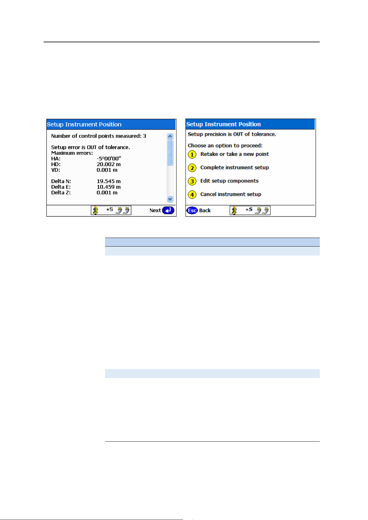
Establishing the Position and Orientation of the Total Station on the Jobsite (Station Establishment) 6
11. Tap Next. The Set Up Instrument Position dialog appears, which shows that you
have measured one control point. Click
Next. To add extra points, select
Retake or take a new point and then repeat Step 4 through Step 10.
B
Tip – When the map view appears, the first measured point is highlighted with a green
circle, which indicates that it has already been measured.
On completion of the reference control point measurements, the following
screens appear if the measurement is out of tolerance:
12. Select from one of the following options:
Option Description
If the setup is OUT of tolerance
Retake or take a new point Allows you to measure another point or remeasure a
point, if for example, the measurements to date are
out of tolerance and you suspect that you have
measured the wrong point or measured incorrectly.
Complete instrument setup Allows you to accept a failed tolerance if it is "close
enough" for what you are doing. This overrides the
tolerance setting for the system for this specific setup.
Edit setup components Allows you to view all the measured points, and to
review the errors in horizontal and vertical
components for each point. The most suspect
observation is highlighted, and allows you to select,
deselect, or reselect components for use in the
position computation.
Cancel instrument setup You can cancel the total station setup and restart the
station establishment process or move to another
location and try again.
If the setup is IN tolerance
Retake or take a new point Allows you to measure another point or remeasure a
point, if for example, the setup is within the tolerance
specified, however you think the precision could be
improved by eliminating or remeasuring a point or
point component.
Complete instrument setup You can complete the station establishment process
and store the computed station position and
orientation, and then move on with measurement or
staking operations.
SCS900 Site Controller Software Total Station User Guide 51
Page 54
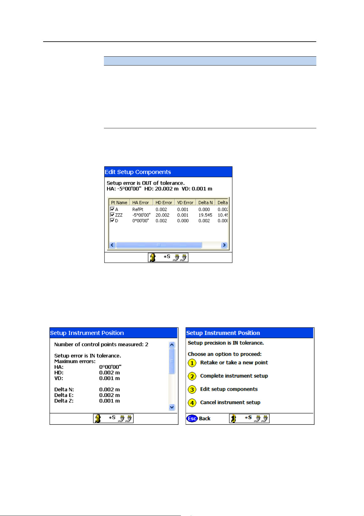
6 Establishing the Position and Orientation of the Total Station on the Jobsite (Station Establishment)
Option Description
Edit the setup components Allows you to view all the measured points, and to
review the errors in horizontal and vertical
components for each point. The most suspect
observation is highlighted, and allows you to select,
deselect, or reselect components for use in the
position computation.
Cancel instrument setup You can cancel the total station setup and restart the
station establishment process or move to another
location and try again.
13. If you feel that you can improve the accuracy of the computed location by
manipulating some of the measured points, select
Edit Setup Components. The
following dialog appears:
This screen shows all the measured control points and the computed errors
associated with each point.
14. Enable or disable points that contribute to the solution, and see what effect it
has on the solution.
15. When you are satisfied with the solution, tap
Save. The following screen
appears:
52 SCS900 Site Controller Software Total Station User Guide
Page 55
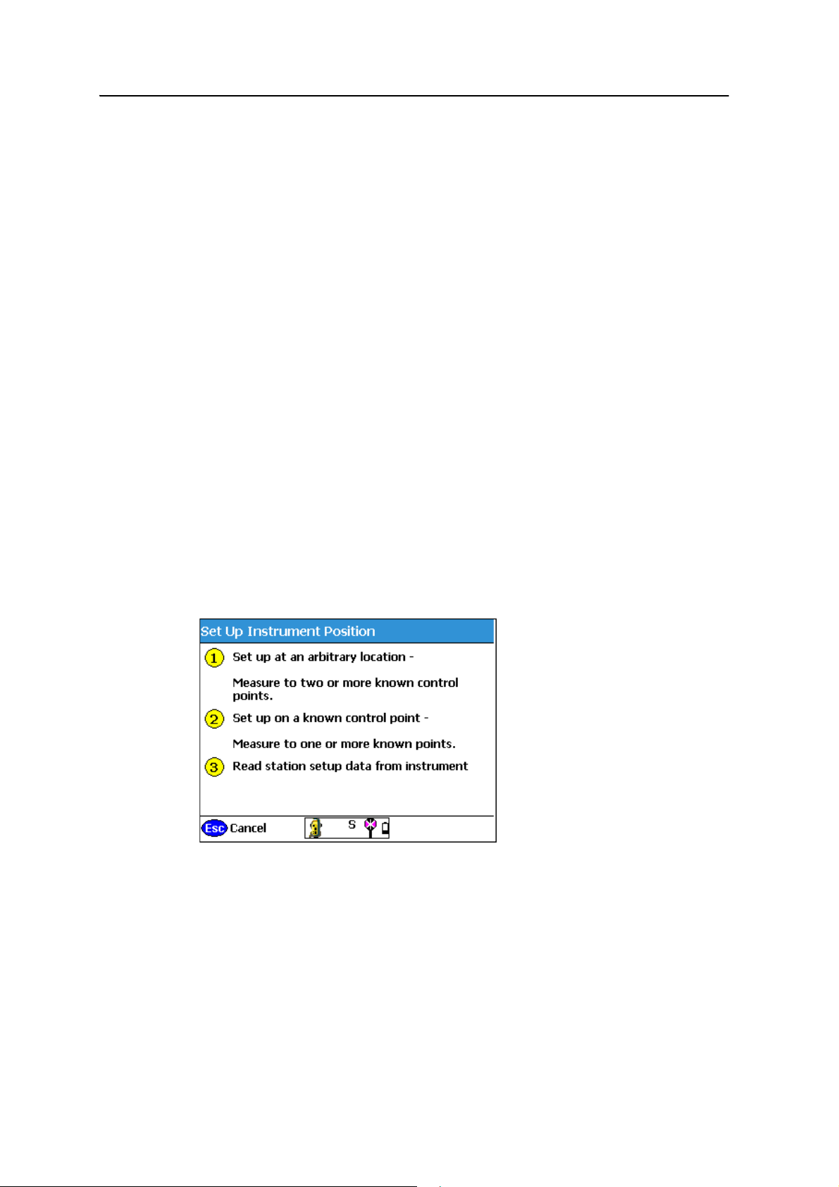
Establishing the Position and Orientation of the Total Station on the Jobsite (Station Establishment) 6
16. Select Complete instrument setup to set the correct orientation of the total
station. You can either proceed with site measurements or set up the total
station for use with machine control (ATS, or SPSx30 only) (see Chapter 7,
Setting Up an ATS or SPSx30 Total Station for Machine Control).
B
B
Tip – If you do not know the name of the reference point being selected when carrying
out either station establishment process, simply move the target to the point that you
want to measure, or point the total station at an already established target. The target
indicator moves in the map to that location, making it easy to identify and select the
correct point from the map view.
Tip – When selecting the third or subsequent point in either station establishment
process, an Aim button appears in the display. To turn the total station to the selected
point location, tap Aim. The total station turns directly to the selected point.
Reading station setup data from the total station
After you have performed a station establishment, the total station stores the
information in its memory, so that other controllers running the SCS900 software can
access it. Subsequent users can save time by simply retrieving the station setup
information from the total station’s memory without setting up at an arbitrary location
or on a known control point again.
A machine control system can also retrieve the position and orientation of the total
station, so that the machine can be correctly positioned.
To use the total station’s position and orientation as established from the last
performed total station establishment, select
instrument:
Read station setup data from
SCS900 Site Controller Software Total Station User Guide 53
Page 56
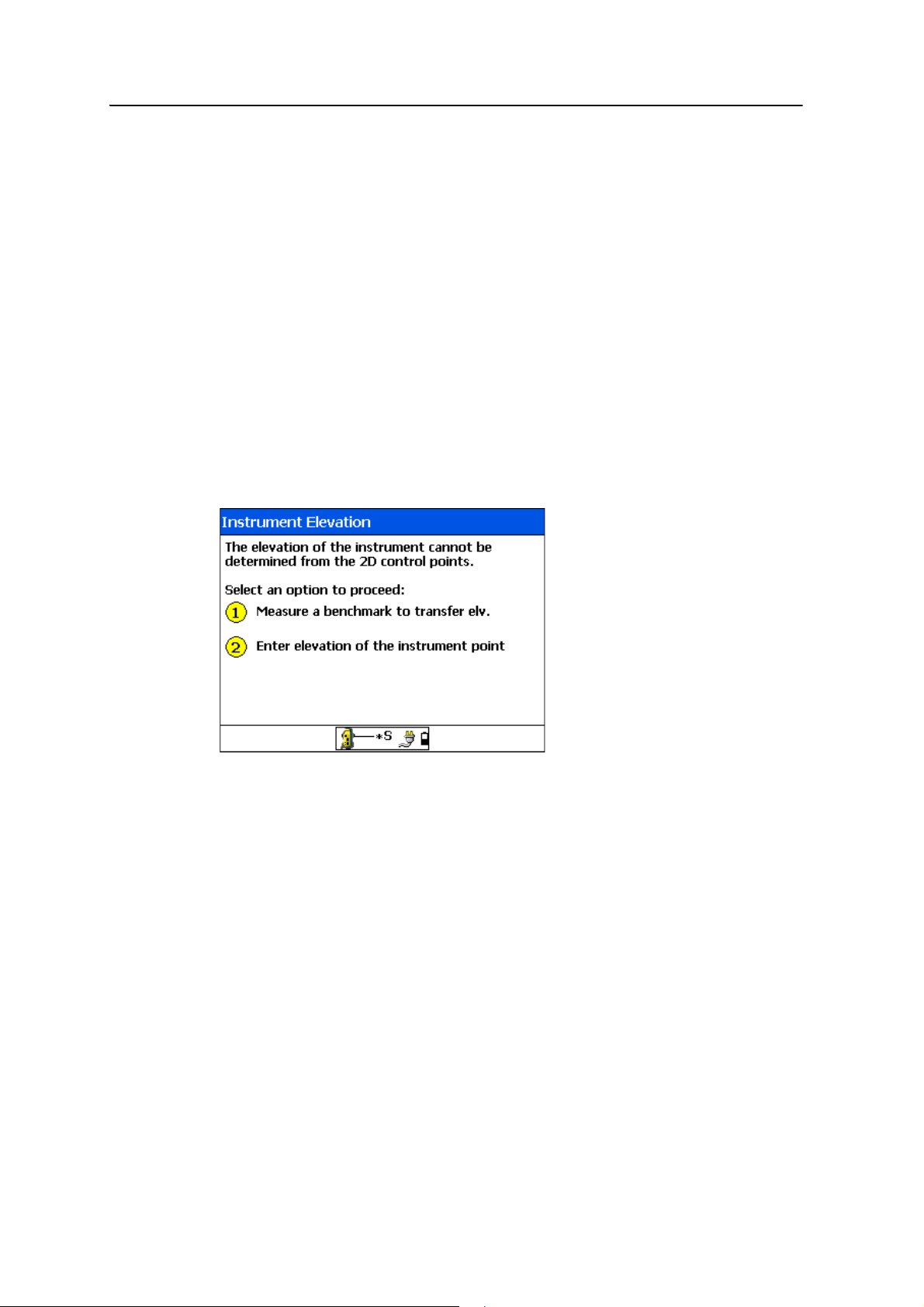
6 Establishing the Position and Orientation of the Total Station on the Jobsite (Station Establishment)
Completing a station establishment where the height of the setup point has not been determined
If the height of the total station has not been established at the end of the station
establishment process, the software prompts you to either enter a known height for
the setup point or to height from a known benchmark location defined as a 1D or 3D
point. This occurs when:
• setting up at an arbitrary location, the reference control points measured were
all 2D points
• setting up a known point, the known point and reference control points selected
were all defined as 2D points
The benchmark point is measured in the same way as any other control point. It is
used in combination with the target height and instrument height to determine the
setup point elevation.
When you tap
determined, the following dialog appears:
Complete instrument setup where Height has not been
54 SCS900 Site Controller Software Total Station User Guide
Page 57
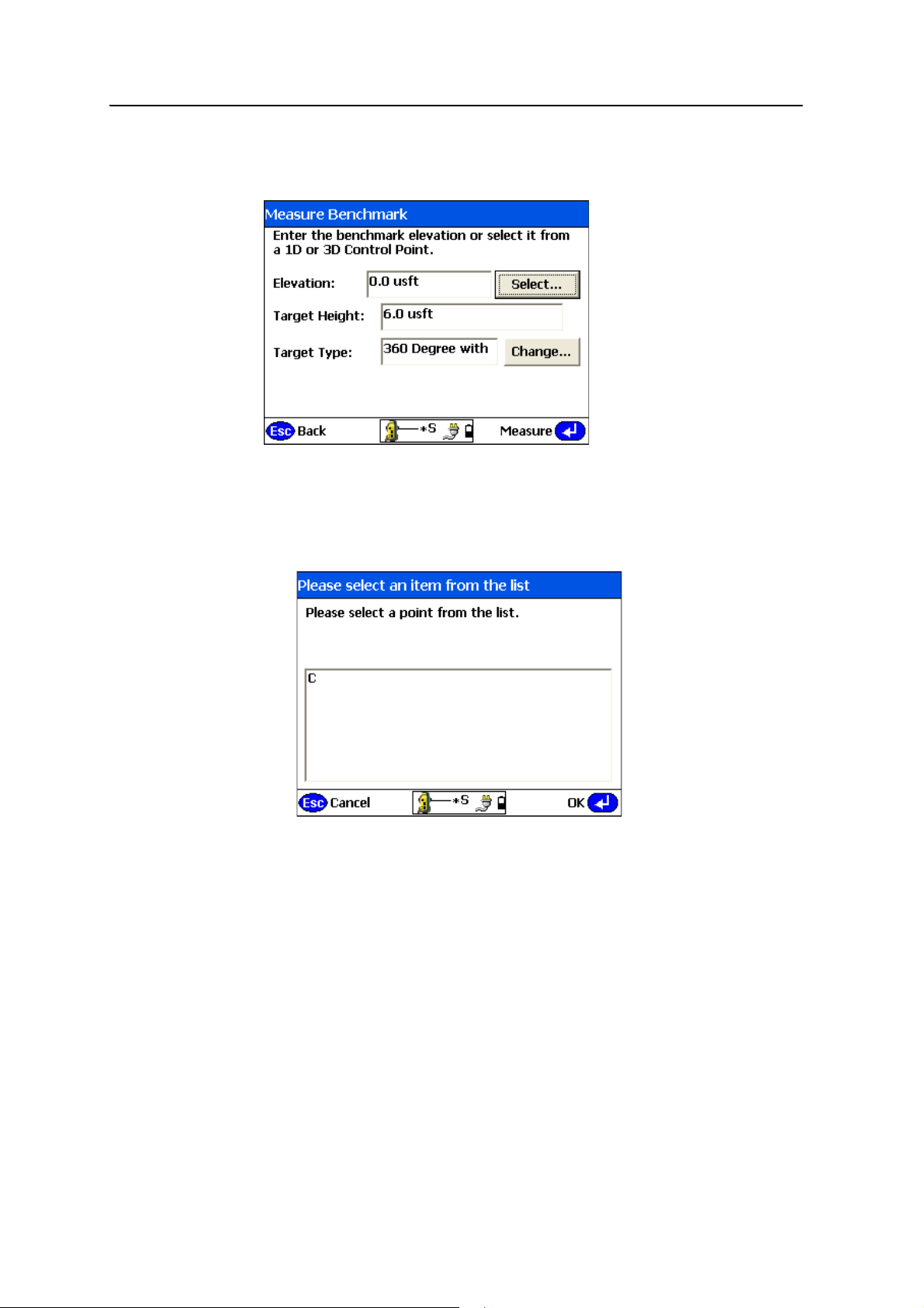
Establishing the Position and Orientation of the Total Station on the Jobsite (Station Establishment) 6
To measure a 1D or 3D control point to transfer the elevation to the setup point:
1. Select
Measure a benchmark to transfer elev.:
2. If the control point does not exist in the control point file, enter the elevation of
the benchmark elevation and the target height to be used. Go to Step 4.
3. If the control point is in the control point file:
a. Tap
Select:
The control point list shows all 1D and 3D points. 2D points are excluded.
b. Select the point from the control point list and tap
SCS900 Site Controller Software Total Station User Guide 55
OK.
Page 58
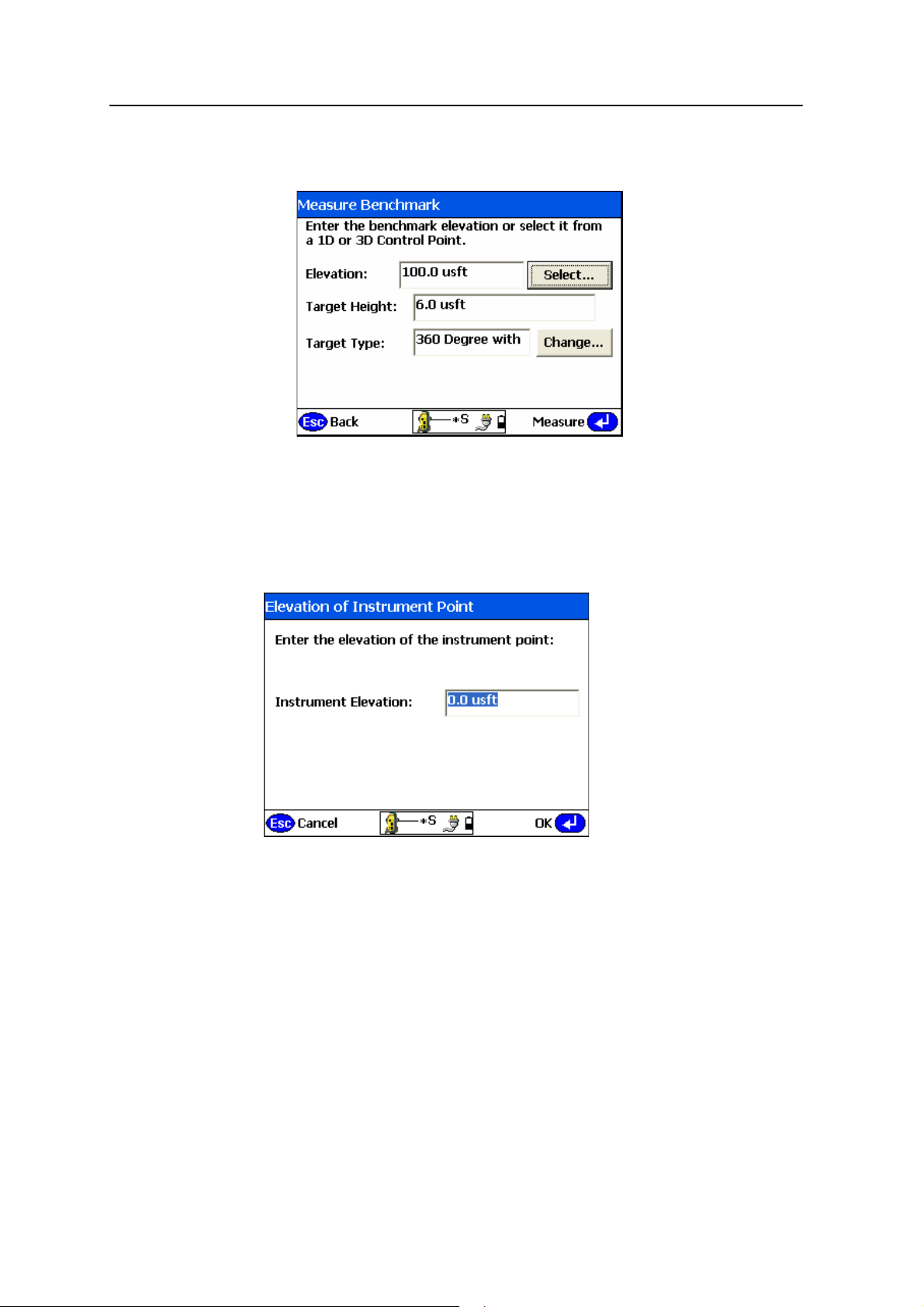
6 Establishing the Position and Orientation of the Total Station on the Jobsite (Station Establishment)
The Measure Benchmark dialog now shows the elevation of the selected
control point:
c. Enter or accept the target height and the type of target.
4. Tap
Measure to take the measurement.
To enter the elevation of the instrument setup point to provide elevation to the
instrument setup:
1. Select
2. Enter the elevation of the total station and then tap
Enter elevation of the instrument point:
OK.
The instrument 3D setup is complete.
56 SCS900 Site Controller Software Total Station User Guide
Page 59

CHAPTER
7
Setting Up an ATS or SPSx30 Total Station for Machine Control
In this chapter:
Using the ATS or SPSx30 UTS for
machine control applications
This chapter describes how to set up the Trimble
ATS (Advanced Tracking Sensor), or SPSx30 total
stations with the SCS900 Site Controller software
for use with a Trimble machine control system.
7
SCS900 Site Controller Software Total Station User Guide 57
Page 60
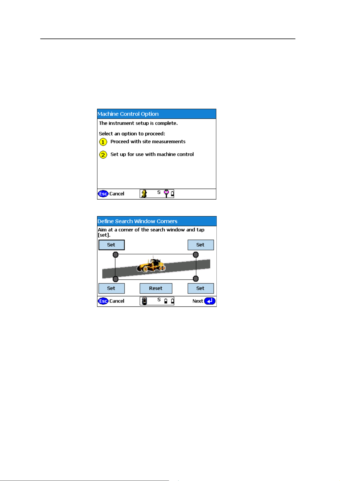
7 Setting Up an ATS or SPSx30 Total Station for Machine Control
Using the ATS or SPSx30 UTS for machine control applications
Having completed the ATS or SPSx30 total station setup, you can now complete
additional steps to prepare the instrument to work with machine control (Trimble
BladePro
SiteVision
®
3D grade control system, GCS900 Grade Control System, and the
®
software).
1. From the following screen, select
The following dialog appears:
Setup for use with machine control.
If you are tracking a machine and the target becomes lost for any reason, the
total station continues to turn at a constant horizontal and vertical speed for a
short period, in the expectation that the target will appear on the same
trajectory when it clears the obstruction. A line-of-sight obstruction, a passing
vehicle, or simply losing the target because of movement speed (for example,
speed that is too high at short range) can cause the total station to lose the
58 SCS900 Site Controller Software Total Station User Guide
Page 61

Setting Up an ATS or SPSx30 Total Station for Machine Control 7
target. When the target is ‘lost’, that is, the above method failed to reacquire the
target, the total station searches for the target. The total station has two search
modes:
Mode Description
Quick Search Initiated as soon as the target is ‘lost’.
This search is centered on the last known location, and inside a window
defined by a horizontal angle width (e.g., 15°) and a vertical angle
width (e.g., 15°). The machine control software sets the values for the
search window.
Full Search This search looks inside a larger window, defined by the dialog shown
previously. When the Quick Search mode fails to locate the target, the
Full Search mode is initiated.
2. Set the window for the Full Search mode; do the following:
– Accommodate the fact that the prism can be mounted on an electric mast,
and that the window of operation at close range will be higher or lower
than at longer ranges.
– Ensure that you set the window of operation to cover the extents of all
grading operations to be completed from that location (instrument setup).
B
– Ensure that if the machine is taken outside that window, to turn around or
to bench on a known height point, those locations are also included in the
search window.
3. You can define either the upper left/lower right extents of your search window
or the upper right/lower left extents of your search window. Ensure that you
take a good look at any high or low points in the area where you will be working
and then define your search window to what most closely resembles the actual
working area in front of you. Do one of the following:
– Point the total station to an upper left location and then to a lower right
location; tap the appropriate
– Point the total station to an upper right location and then to a lower left
location, tapping the appropriate
Tip – As soon as the first corner is defined, the only option available in the software is to
define the opposite corner. For example, if you define the upper right extent first, the
lower left corner is only made available to define. If the lower right corner is set first, then
the upper left corner is only made available to define.
Set button at each pointing.
Set button at each pointing.
SCS900 Site Controller Software Total Station User Guide 59
Page 62
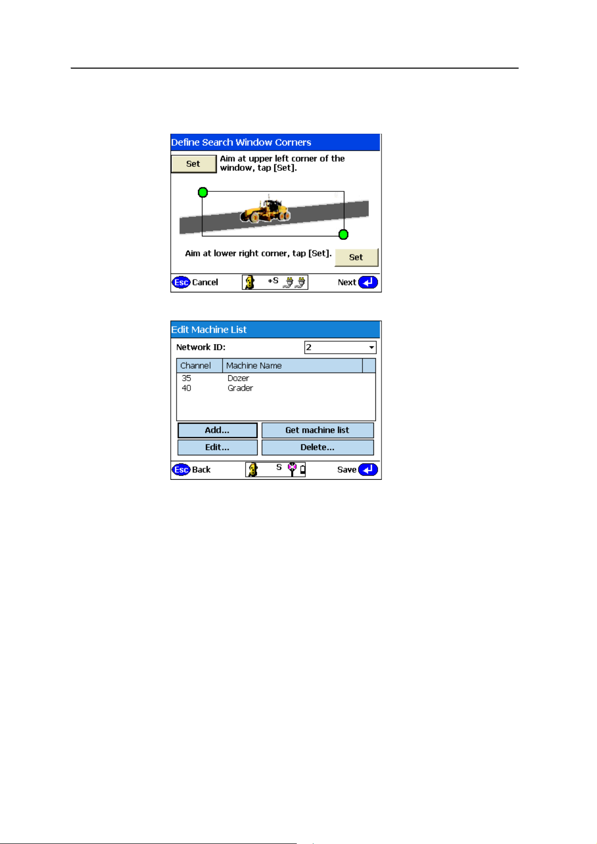
7 Setting Up an ATS or SPSx30 Total Station for Machine Control
The total station measures the horizontal and vertical angles to those locations
using its angle sensors, and the gray circle changes to green to indicate that the
location has been accepted:
4. Tap
Next:
A single SPSx30 total station can be shared by multiple machines and a single
SPS robotic rover pole at, for example, at a bridge structure. Only one user can
use the total station at a time, but when not in use, it continually scans a
predefined list of radio channels assigned to different machines and the last
used site positioning system channel in sequence, looking to see if anyone needs
access to the total station. When a machine or site positioning system calls the
total station, it connects and provides a positioning service. When completed,
the total station returns to standby mode and becomes available to the radio
channels previously loaded to the instrument. To facilitate this process, in the
set up for machine control process, you can create a list of machines, each with a
name and a specified radio channel, for example:
– CAT 140H Grader 1 33
60 SCS900 Site Controller Software Total Station User Guide
Page 63
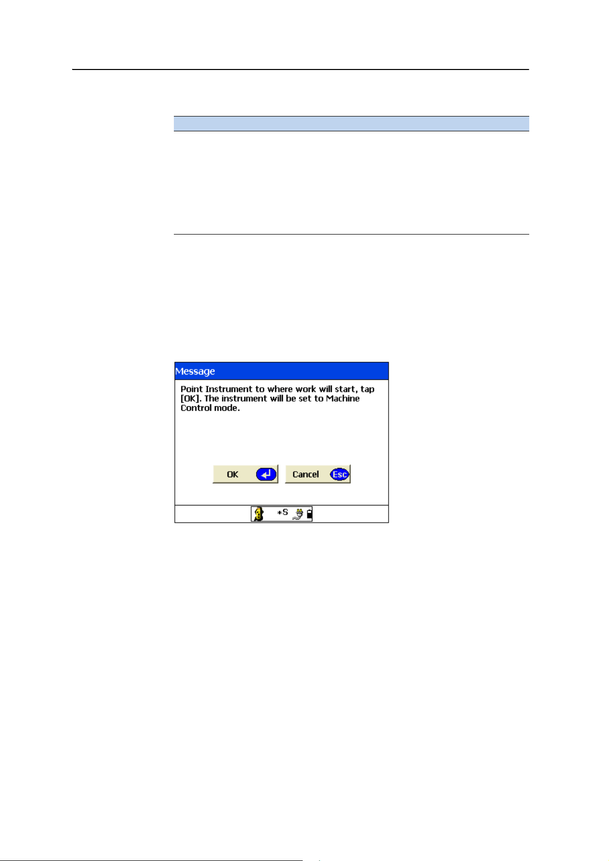
– CAT D6 Dozer 1 34
Tap … to …
Add
Edit machine list
Delete
Get machine list
create a new radio channel/machine name pair entry to the
machine list. The machine list can contain a maximum of 10
entries. Each radio channel can be used only once in the machine
list.
change the entry that is currently highlighted.
delete the entry that is currently highlighted.
get the current machine list from the total station’s memory to
review and edit it.
Setting Up an ATS or SPSx30 Total Station for Machine Control 7
B
B
Tip – Ensure that all assets in the machine list have the same network ID.
Tip – The machine list is scanned sequentially whenever the total station is placed in
standby for machine control. The more entries in the list, the longer the scan takes to
complete a full cycle and therefore the slower the initial connection will be with the total
station. If you are not continually using the entries in the list in earthmoving operations,
delete the entries from the list to speed up initial connection times.
5. Enter the name of the total station and then tap Finish. The following dialog
appears:
6. If you are operating at the total station, point it at the MT900 target on the
machine. When the machine connects to the total station, this speeds up the
initial search and lock-on process for the total station as it instantly “sees” the
target and locks to it.
The total station goes into standby mode for machine control and then it scans
the machine list in chronological order until a machine is found calling the
instrument on one of the channels.
7. Tap
OK. The SCS900 software now disconnects from the total station.
SCS900 Site Controller Software Total Station User Guide 61
Page 64
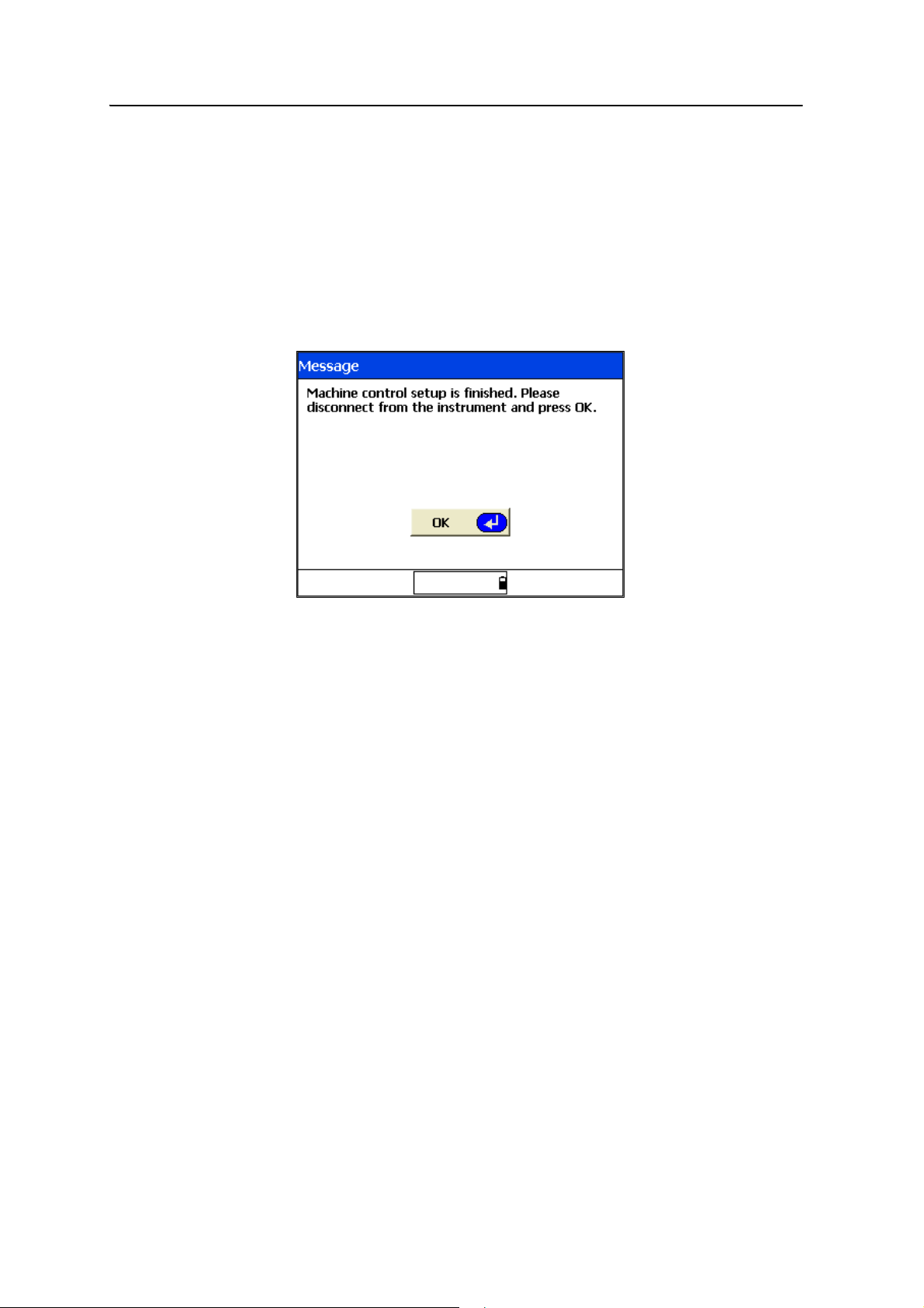
7 Setting Up an ATS or SPSx30 Total Station for Machine Control
8. Move to the machine and initiate connection to the total station. Do one of the
following:
– If you are operating the ATS with an external SNB900 radio for
compatibility with the on-machine radio system (SiteNet
™
900 radio or
SNR900 radio-modem), detach the controller from the total station and
then connect the SNB900 radio-modem.
– If you are using an ACU controller, the radio can be connected at all times.
For details of how to configure and set up the system for use with the
SNB900 radio, refer to the SNB900 User Guide, version 1.20 or later.
9. Tap
OK.
62 SCS900 Site Controller Software Total Station User Guide
Page 65

CHAPTER
8
Using Basic Mode 8
In this chapter:
Icon panel
Total Station Basic mode
When connected to a total station, an icon panel
appears at the bottom of the screen. To access
frequently used total station functions, tap the
icons. The icons in the panel change based on the
current operation mode and the status of the
total station.
The Basic mode is available from all menus and
all map screens during measurement or stakeout.
The Basic mode enables you to make simple
measurements and to quickly access frequently
used functions. Some items may be unavailable
or disabled because of the current settings.
Trimble recommends that you use the measuring
mode to control the operational characteristics
of the total station and that you use Basic mode
only when necessary.
SCS900 Site Controller Software Total Station User Guide 63
Page 66
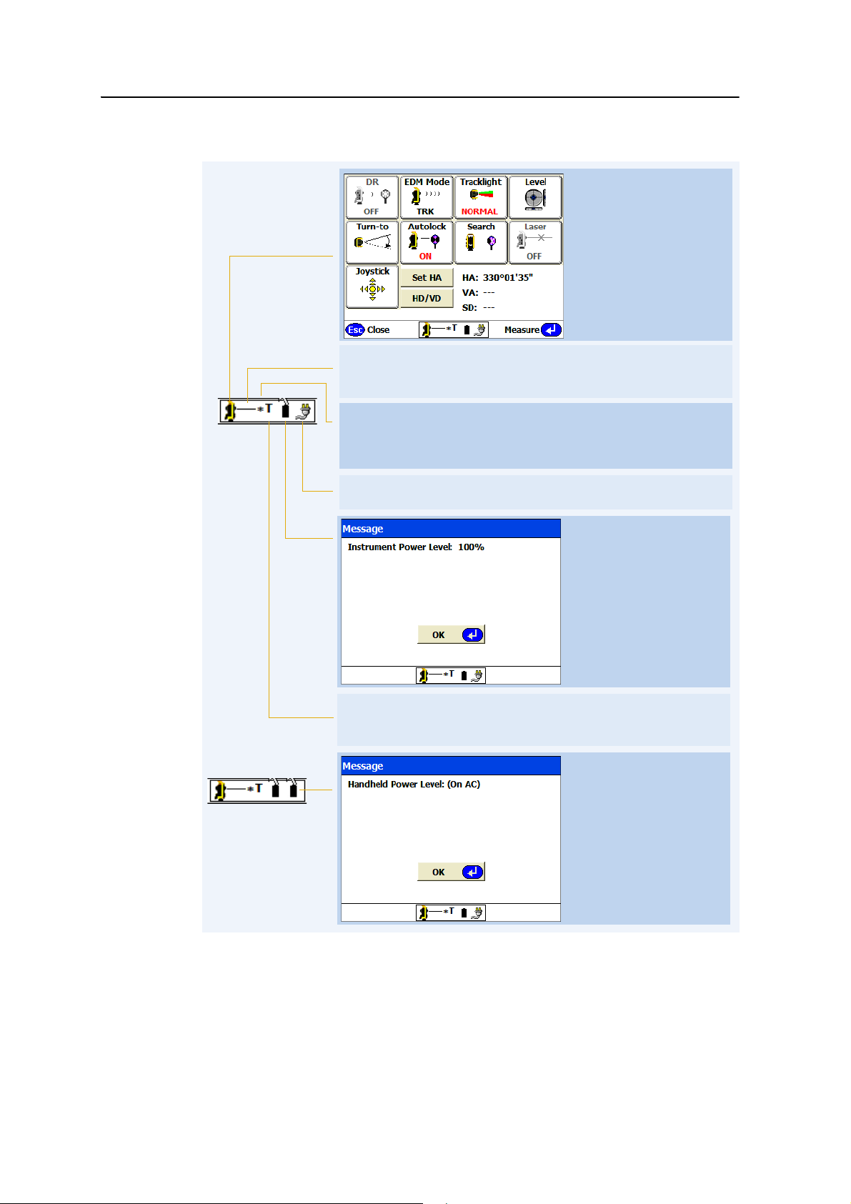
8 Using Basic Mode
Basic mode. For more
information, see page 65.
Internal power level of the
total station.
Note – When working in
Robotic mode, the panel
shows the total station
battery level while working
at the rod.
shows the current battery
level of the handheld
controller (TSC2)
The black line indicates that Autolock
technology (the tracker) is
switched on and is locked to the target. A red line indicates that the
laser pointer is switched on.
The current total station measurement mode:
• T for Tracking (TRK) mode
• S for Standard (STD or Single shot) mode
* indicates that the total station can see the prism or target and can
measure a distance.
No * means that the total station is not getting a return signal from
the prism or target and cannot measure a distance.
External power source when using the Trimble CU controller on the
total station.
Battery strength of the
controller when working
robotically.
Side view of the total
station – the total station is
locked to the target.
Front view of the total
station – the total station is
not locked to the target.
Icon panel
Note – The laser pointer and Autolock functions are mutually exclusive. The Autolock and
DR Reflectorless modes are also mutually exclusive. Turning on Autolock automatically
turns off DR mode and the laser pointer. Turning on DR mode automatically turns off the
Autolock function.
64 SCS900 Site Controller Software Total Station User Guide
Page 67
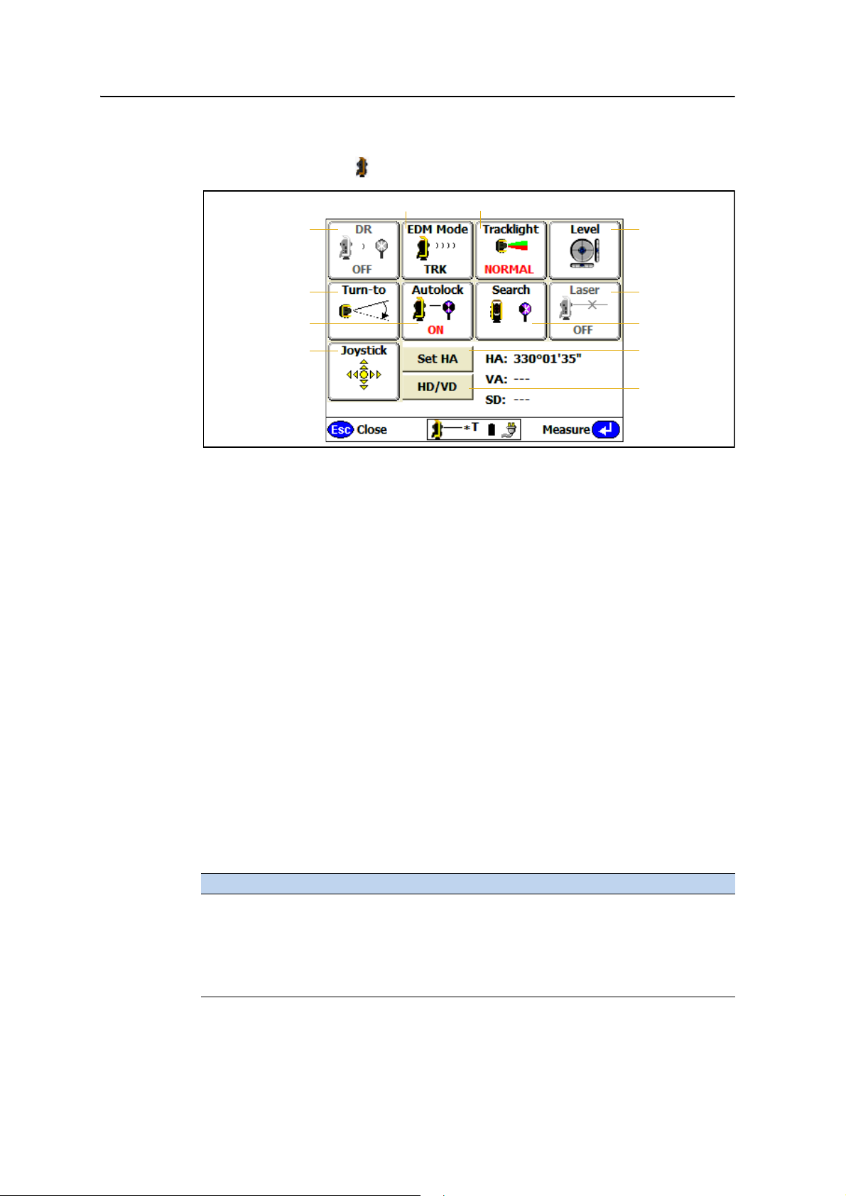
Total Station Basic mode
See page 66
See page 67
See page 71
See page 67
See page 70
See page 69
See page 68
See page 71
See page 72
See page 66 See page 66
Tap the instrument icon to open the Basic mode.
Figure 8.1 Basic mode functions
The following functions enable you to change the default behavior of the total station
or access specific tools:
Using Basic Mode 8
• EDM mode
• Tra ckl ight
• Level – Electronic level and dual axis compensator
• Turn-to – Turn the total station to a specified location
• Joystick – Use to reacquire the target after a loss of lock when working in
®
Robotic mode
For example, when staking a point, the default EDM mode is TRK. For more accurate
work, you may want to change the default mode to STD. Using Basic mode allows you
to change the default behavior of the total station. However, changing the EDM mode
does not change the EDM mode for navigating to and locating a point; it only changes
the behavior when you tap
Record to record a shot or tap Stake to stake a point. While
moving around the jobsite between points, the total station is always in TRK mode so
it can provide a real-time map update of your position.
The measuring modes described in Chapter 13, Measuring Modes are how the
performance settings of the total station are typically selected ( for example, Standing,
Walking, Vehicle, DR, or DR Scanning modes). These modes directly control the use of
the DR mode, Laser Pointer, Autolock, and EDM mode as shown below:
Action EDM mode Autolock mode Laser pointer DR mode
Standing STD or TRK On (if available) Off only Off only
Walking TRK only On only Off only Off only
Vehicle TRK only On only Off only Off only
DR STD or TRK Off only On or Off On only
DR Scanning TRK only Off only On or Off On only
SCS900 Site Controller Software Total Station User Guide 65
Page 68
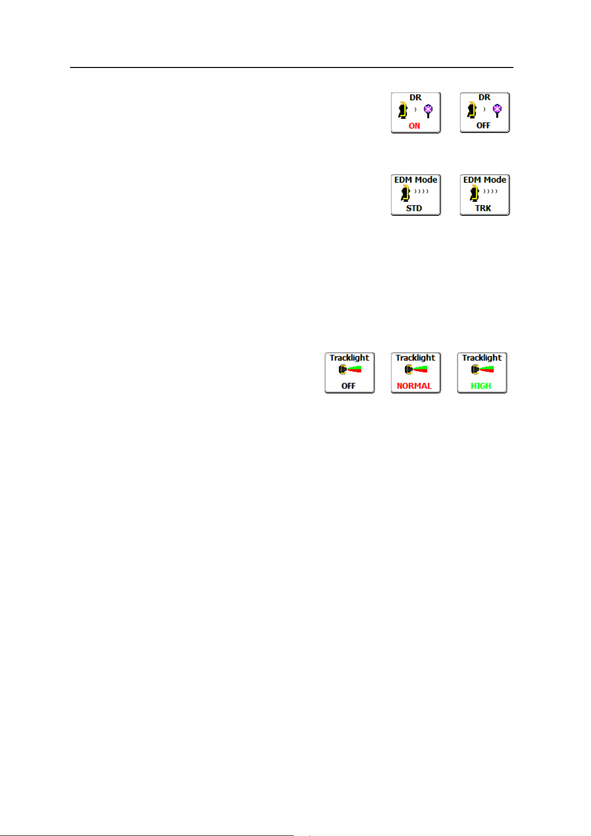
8 Using Basic Mode
DR
EDM mode
Controls whether or not the total station can measure
without a reflector to a target using the system’s DR
Reflectorless capability.
The options are:
• STD (Standard – also known as Single Shot mode)
• TRK (Tracking – also known as Continuous Measurement mode). This is the
default mode.
In STD mode while working with Autolock or in Robotic mode, the total station
averages the HA and VA angle readings for a period of time before measuring the
distance. A complete measurement takes approximately three seconds. The averaging
of the HA and VA allows for more accurate measurements to be achieved to a
handheld pole. Distance accuracy in STD mode is higher than in TRK mode.
Tracklight
Use the Tracklight mode to provide a
visible guide light for stakeout and
robotic operations. The next time the
total station is turned on, the last used setting becomes the default setting.
The light is a split-field red and green light. You will see a red or green light depending
on where you are standing referenced to the instrument’s pointing.
When operating at longer ranges or in very bright sunlight, select the High intensity
option to increase the visibility of the tracklight.
While working at the rod, a glance to the total station indicates whether or not it is
tracking you. If the total station is turned towards the desired location while staking,
you can navigate into the correct line using the tracklight.
66 SCS900 Site Controller Software Total Station User Guide
Page 69
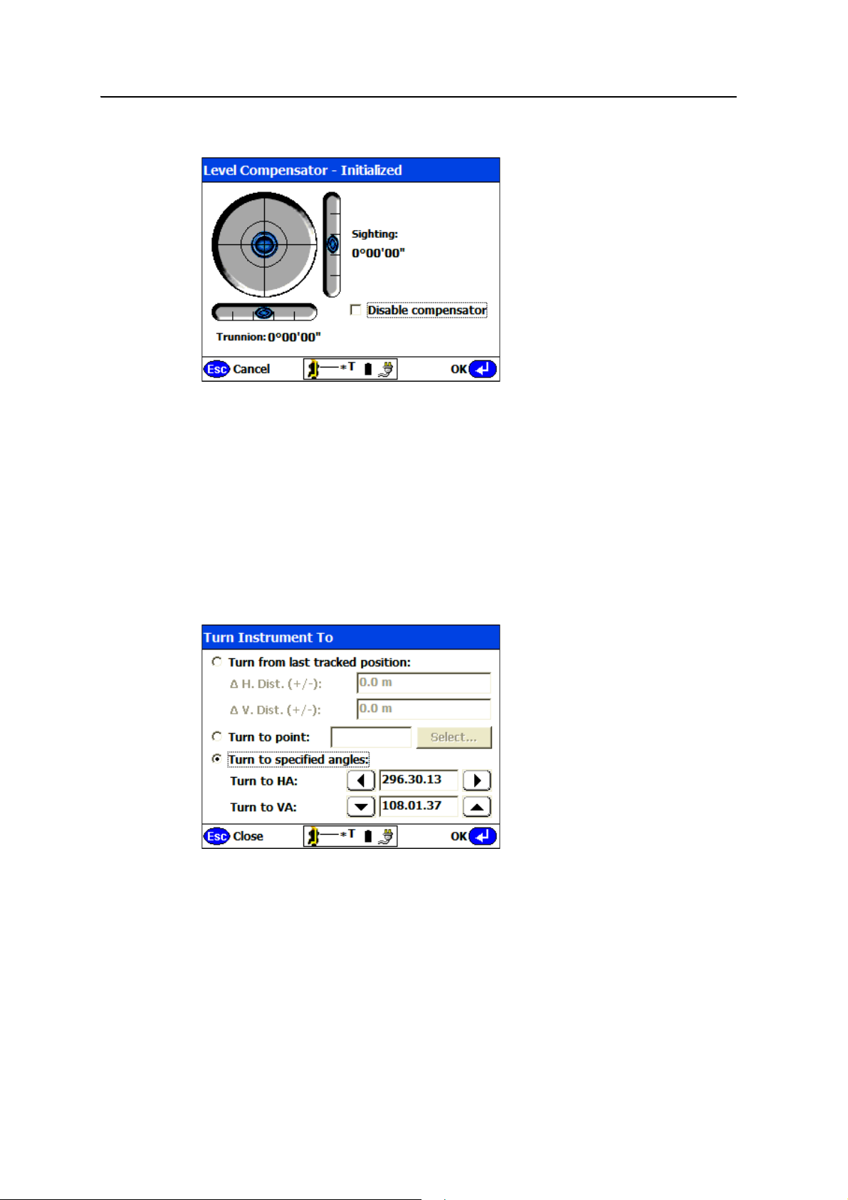
Using Basic Mode 8
Level
The electronic level appears when you start the total station (see page 12).
Use the electronic level to check and relevel the total station, and to change the status
of the compensator.
In most scenarios, the compensator should always be enabled. However, where the
total station is used on a platform that is moving, or if it is set up near a source of heavy
vibration ( for example, near compaction, piling, or drilling equipment), you may need
to turn off the compensator. By default, the compensator is turned on each time you
start the system.
Turn-to
Use the Turn-to function to automatically aim at a specified location. There are three
ways to specify the location:
• Turn from last tracked position
Enables you to pace out the distance while moving past an obstruction such as a
parked vehicle, and then turn the total station to an estimated location based on
the estimated horizontal and vertical distances moved and in the last known
SCS900 Site Controller Software Total Station User Guide 67
Page 70
8 Using Basic Mode
direction of movement. The distances entered are used to compute the angle
change based on the last known measured position to bypass the obstruction.
• Turn to point
Enables you to select a previously measured or staked out point in the map view
and then turn the total station to that location. This can be used to send the
total station to a point that can easily be located on the ground such as a curb
corner, and then quickly navigate to that position to continue operation.
• Turn to specified angles
Enables you to enter a horizontal and vertical angle, or to step the current
angles by an even increment from the last known location to bypass an object,
beyond which work can continue. Step the last measured angle reading using
the arrow keys beside the angle values, or simply enter new values to which to
turn the total station.
Ta p
OK. The total station turns to the selected location. When working in Robotic
mode or with Autolock technology, walking into the total station’s line-of-sight causes
it to automatically lock to the target. Use the tracklight to define the current
line-of-sight to make it easier for the total station to reacquire the target.
Autolock mode
Autolock technology enables the total station to lock
onto the target and track it while moving about the
jobsite.
For total stations equipped with Autolock technology, the default mode is on when not
using the system’s DR reflectorless capability. For Walking and Vehicle modes, the total
station must be equipped with the Autolock technology and Autolock will always be
switched on.
68 SCS900 Site Controller Software Total Station User Guide
Page 71
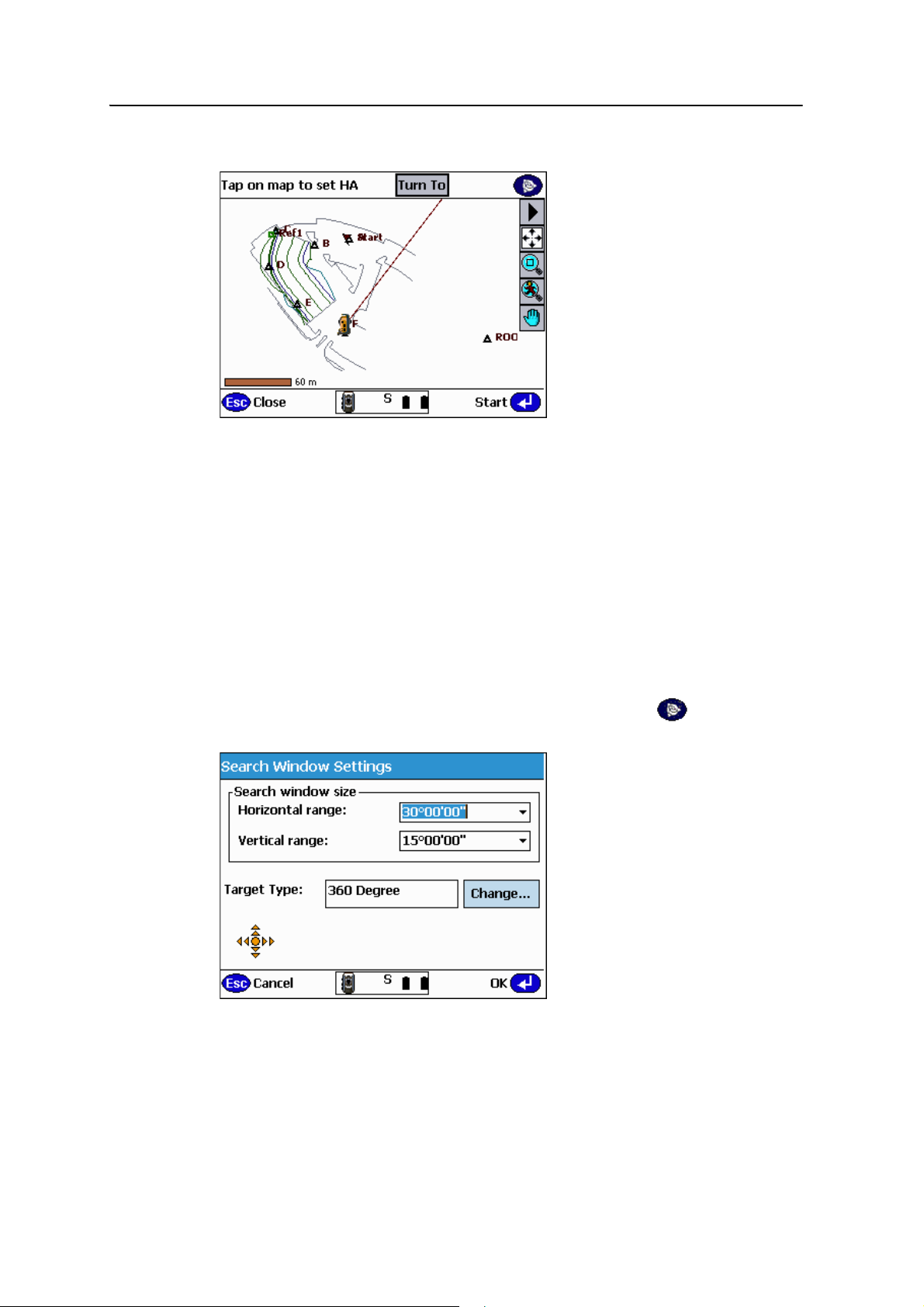
Using Basic Mode 8
Search
When the target is ‘lost’ (the total station cannot see the selected target type), the total
station search functions are automatically initiated during all operations.
In the search view, tap anywhere on the map to automatically turn the total station
horizontally to point at that location. The current pointing direction for the total
station is displayed as a red line connected to the instrument location icon (as shown
above).
When using a TSC2 or Trimble CU as your field controller, the spider key is active
when the software is in the Search view:
• To turn the total station using the spider key, you must deselect the pan and
zoom keys. The spider key will work in joystick function.
• To pan the map view using the spider key, select the pan or zoom keys.
Access the search control settings through the Trimble Key icon in the top right
of the search view:
Use the settings in this screen to define the default search window. Define the
horizontal range and vertical range of your search window. The total station then uses
the search window whenever it initates an automated search. This happens when loss
SCS900 Site Controller Software Total Station User Guide 69
Page 72
8 Using Basic Mode
of lock occurs while working. The joystick is available from the search window, so that
you can manually steer the total station to your location if, for example, the total
station has not yet been oriented and a standard automated search would not work.
Tap to open the Turn-to dialog (see page 67). Use this dialog to turn the total
station to a location defined by a horizontal and vertical distance moved, to a
measured or defined stakeout point, or to a specified horizontal and vertical angle.
Ta p
Start to initiate the search function based on the current pointing of the total
station. The search function is executed within the currently defined search window.
B
Laser
Tip – The best way to use the search function is to turn the total station horizontally to
your current location using estimated screen taps to get the total station close, then use
the vertical movement arrows to get the total station pointing close in 3D (you typically
know that you are now above or below the last measured location, so moving the total
station up or down accordingly is relatively easy to do). Once you are close, walk and
place the target in the total station’s line-of-sight, or tap Start to initiate the search
process at the current total station pointing location.
Use the laser pointer to provide a visible red spot at the
current pointing location of the total station.
The laser pointer should be coaxial with the cross-hair of the telescope; adjust it if
necessary. For more information, refer to your instrument manual.
Typically, the laser pointer is used in combination with DR reflectorless mode to
highlight the point to be measured, so that viewing the point through the telescope is
not always necessary. The laser pointer allows heads up pointing of the total station
without needing to look through or to focus the telescope on the point.
The icon changes to show either Laser ON or Laser OFF. The default is Laser ON when
DR (see page 66) is on.
70 SCS900 Site Controller Software Total Station User Guide
Page 73
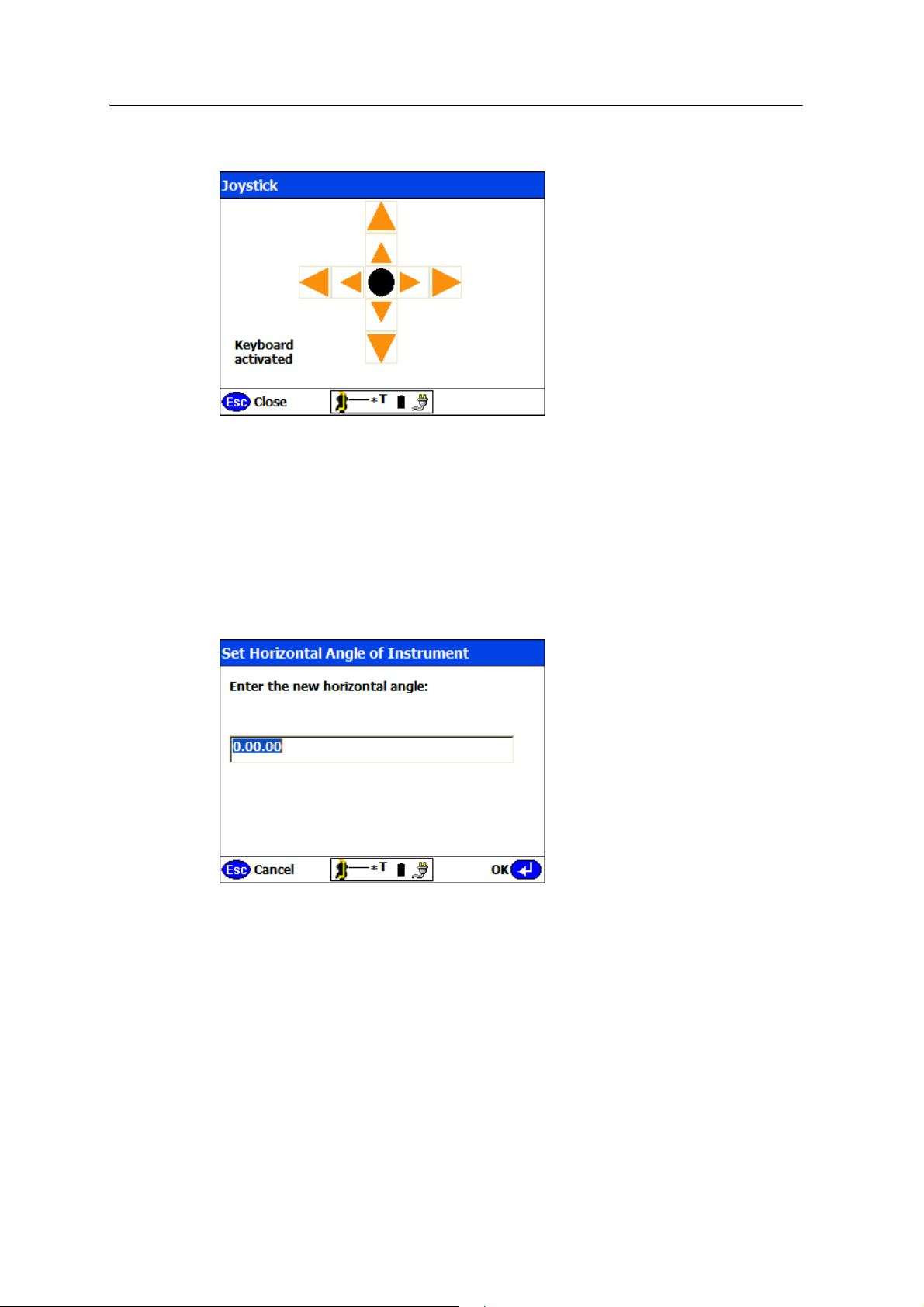
Using Basic Mode 8
Joystick
Use the joystick to quickly steer the total station to the current location, for example,
after loss of lock.
Tap the outer arrows for fast movement or tap the inner arrows for slower or finer
adjustment of the total station pointing.
The arrow keys are also mapped to the arrow keys on the Trimble CU controller or to
the spider key on the TSC2 controller.
Set HA
Use the Set HA function to set the angle reading to a temporary value. This function is
available only in Basic Mode.
For example, you can point along a specific line, set the horizontal angle to 0.0000 and
then use the Turn to function to turn out a right angle.
Setting the HA in Basic mode does not affect the orientation of the total station for
main measurement or stakeout operations.
SCS900 Site Controller Software Total Station User Guide 71
Page 74
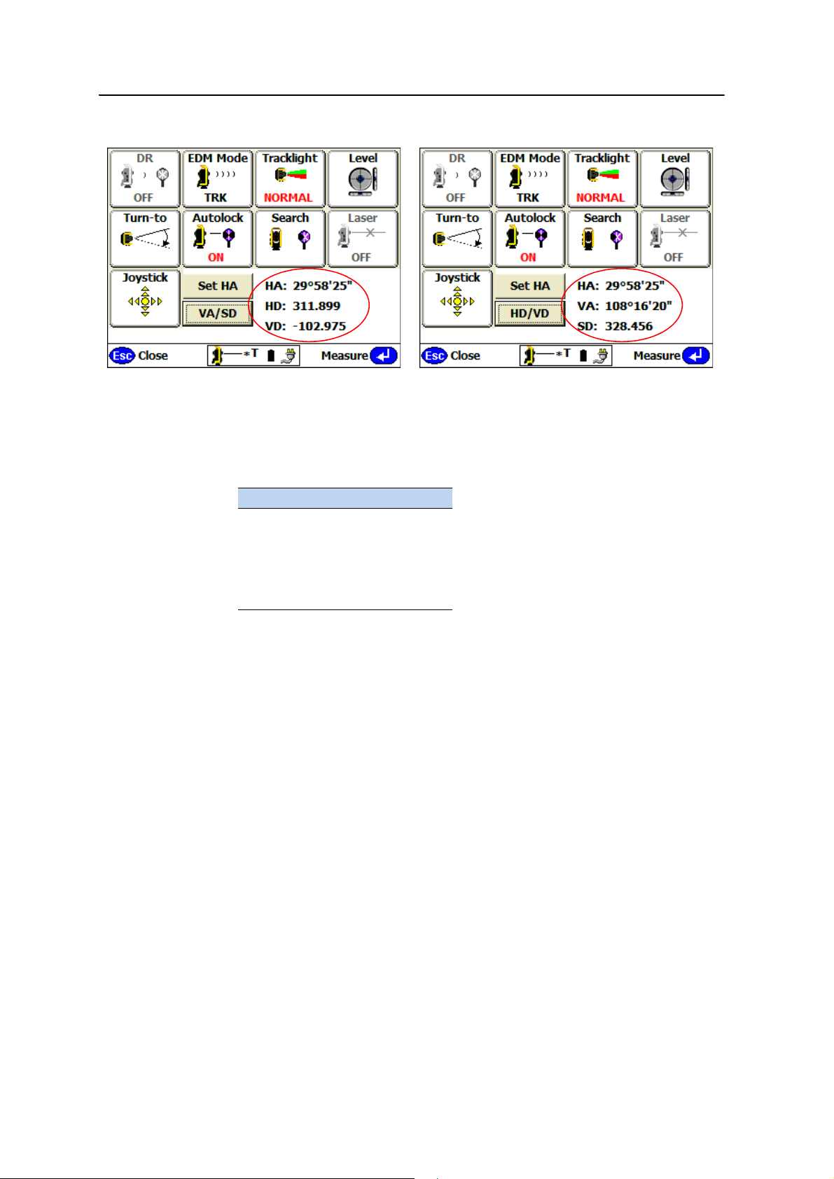
8 Using Basic Mode
HD/VD or VA/SD mode
The HD/VD and VA/SD functions simply change the displayed data values after
measurement in Basic mode only.
• HD/VD mode – Displays HA/HD/VD (shown above left)
• VA/SD mode – Displays HA/VA/SD information (shown above right)
Abbreviation Definition
HA Horizontal Angle
VA Vertical Angle
SD Slope Distance
HD Horizontal Distance
VD Vertical Distance
In TRK mode, the total station automatically measures and updates the above values.
In STD mode, tap
Measure to trigger a distance measurement.
Measurement can be made using a target or using the total station DR reflectorless
mode to measure to any surface in range.
72 SCS900 Site Controller Software Total Station User Guide
Page 75

CHAPTER
9
Advanced Features 9
In this chapter:
Stockpile scan
Profile scan
Automated measurement
Direct reflex (DR) technology is included in your
5600, SPSx10, SPS700, and SPSx30 total stations.
This technology offers many advantages such as:
• Stockpile scanning for accurate volume
calculations.
• Creation of profile lines for applications,
like monitoring quarrying walls for
movement, as-builts of deep cuts such as
side slopes along highways, as well as
monitoring high walls.
The range varies depending on the total station
you are using:
• The SPS610 total station offers DR
Standard technology, which allows you to
measure reflectorlessly, to a maximum
distance of 150 m (492 feet).
• The 5600 total station features DR200+
technology, allowing reflectorless
measuring up to 200 meters (656 feet)
from the instrument.
• The SPS700, SPS710, and SPSx30 total
stations offer DR300+ technology,
allowing reflectorless measurement of
objects up to 300 meters (984 feet) from
the instrument.
SCS900 Site Controller Software Total Station User Guide 73
Page 76
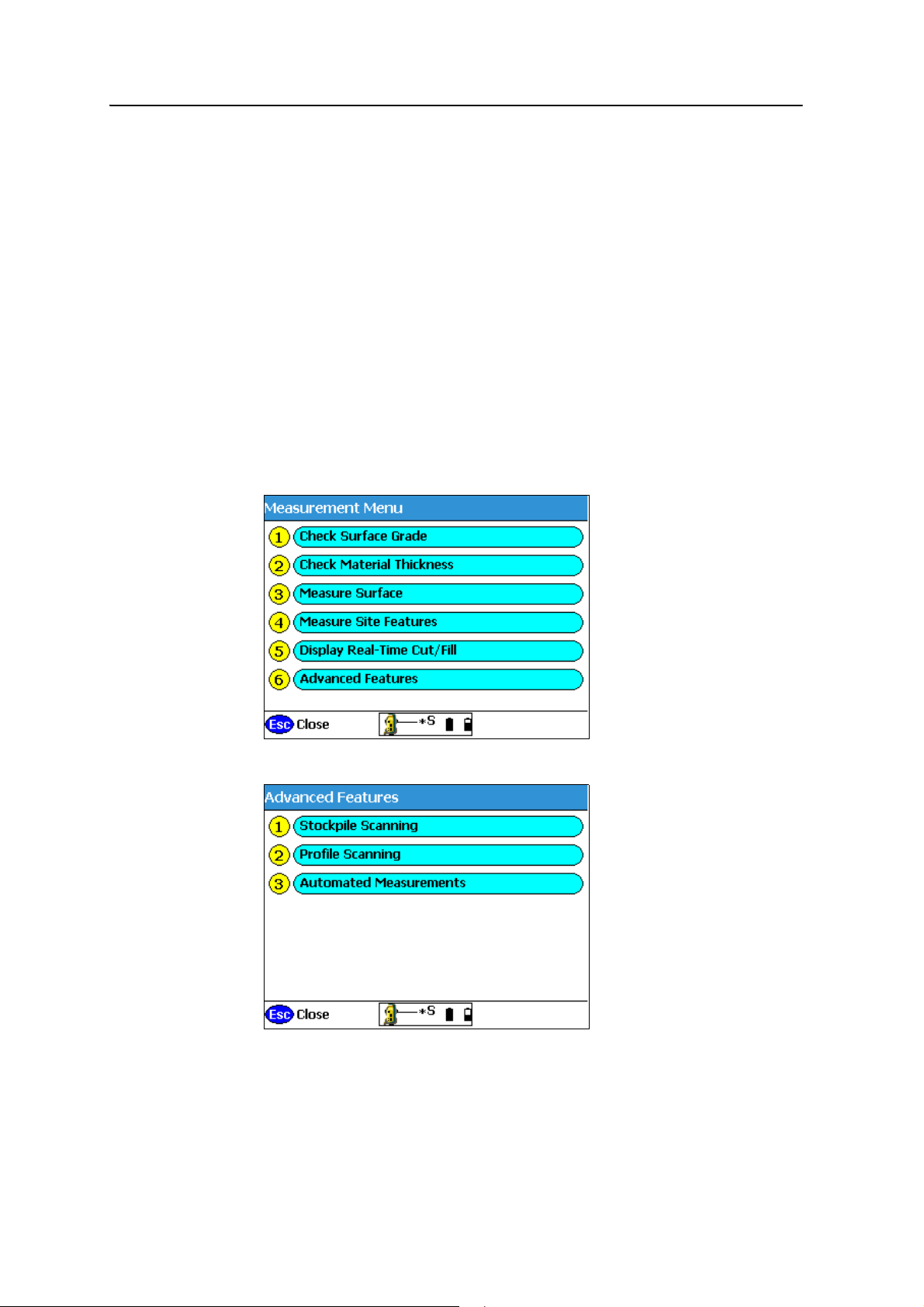
9 Advanced Features
Stockpile scan
The Stockpile scan is designed to collect very accurate data for reporting on the
volume of material that you have or that you have excavated. By scanning the stockpile
or excavation, the need to place a worker in potentially unsafe conditions is
eliminated. Reflectorless measurement technology enables you to set up the total
station and measure to surfaces without using a target or prism.
B
Tip – Given the line of sight restrictions when using a total station, you need to perform a
minimum of two station setups to collect all sides of the stockpile. From your first setup,
measure new control points around the stockpile in locations that will give you the fewest
setups and the best vantage points to scan the largest surface area of the stockpile. This
enables you to collect all sides of the stockpile and have the surface points correctly
related to each other. Once the whole stockpile has been scanned, define a volume
boundary in the Volume & Cogo menu by tapping the points to be used to define the
boundary, and then perform a volume calculation in the field.
To set up stockpile scanning:
1. From the main menu, select
Measurements:
2. Select
74 SCS900 Site Controller Software Total Station User Guide
Advanced Features:
Page 77
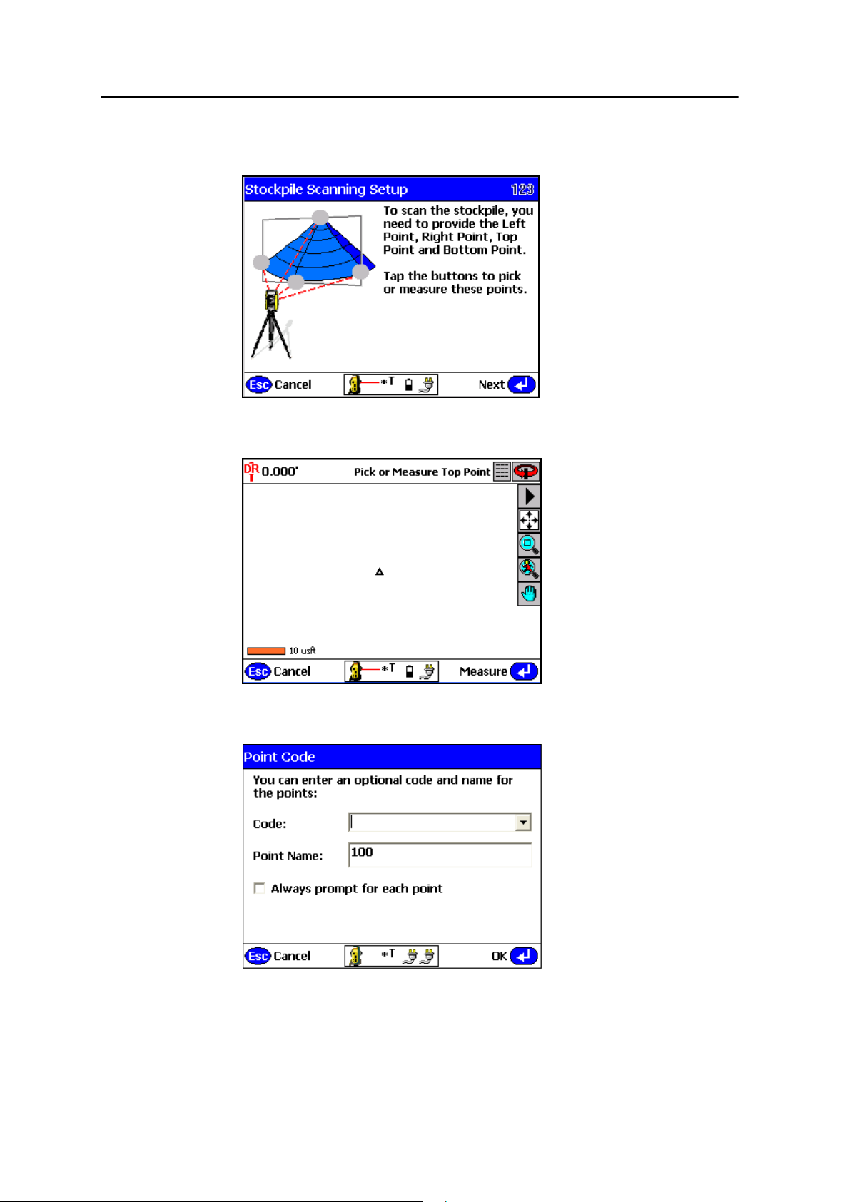
Advanced Features 9
3. Select Stockpile Scanning. The SCS900 software sets the instrument to DR
Mode, and opens the following dialog:
4. Define the shape of your stockpile. Start by tapping the gray dot at the highest
point of the stockpile image on the screen. The map view appears:
5. Manually sight your instrument to the highest point of the stockpile and then
tap
Measure. The following dialog appears:
6. You are then asked for an optional point code and point name. Enter values at
this screen and then tap
OK. The Stockpile Scanning Setup screen reappears.
SCS900 Site Controller Software Total Station User Guide 75
Page 78
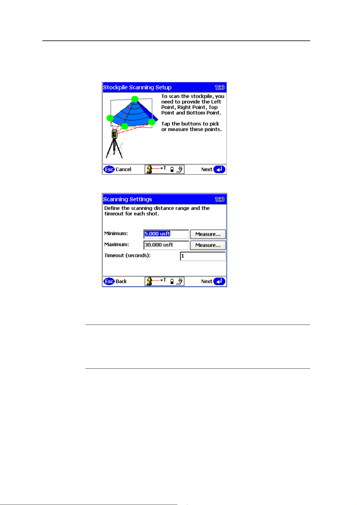
9 Advanced Features
7. Repeat Step 4 through Step 6 to define the bottom left, bottom right, and bottom
most points of your stockpile. Once successfully measured the points appear
green:
C
8. Tap
Next:
9. Define your minimum and maximum distances. Proper use of these settings
helps you collect only relevant points in the field. The software will default to the
recommended Timeout value depending on which instrument is being used.
CAUTION – The values stored in Step 9 are overwritten by the min/max values set in the
DR Target Settings dialog (Chapter 14, Other Total Station Settings and Functions). Ensure
that you check the values set in the DR Target Settings dialog to eliminate confusion by
another operator when they are setting the Stockpile Scan settings. Setting the minimum
distance to 2 meters (6.56 feet) and maximum distance to 300 meters (984 feet) in the DR
Target Settings dialog will eliminate any errors when setting the Stockpile Scan settings.
76 SCS900 Site Controller Software Total Station User Guide
Page 79
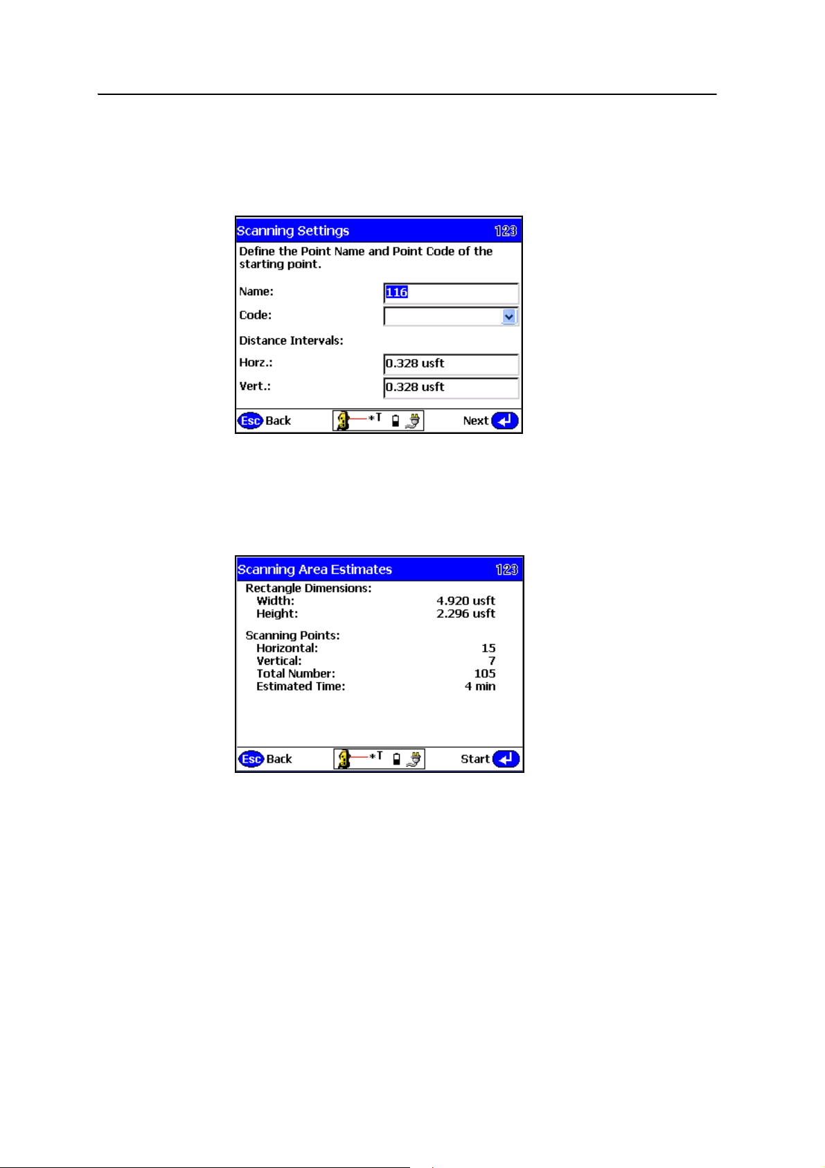
Advanced Features 9
B
B
Tip – When working at the maximum ranges of the DR technology, the Timeout Setting
should be increased. When adjusting the timeout settings, be aware the material being
measured affects the strength of the response signal. Also, the instrument's technology
affects the time it takes to record each individual point. Tap Next. The following dialog
appears:
10. Enter a point name and code and set the distance intervals.
Tip – Setting the distance intervals low results in more measured points; setting the
distance intervals high results in fewer measured points. Keep the size and shape of the
stockpile in mind when entering these values.
11. Tap Next:
The Scanning Area Estimates screen displays the total number of points to be
collected as a result of the dimension and distance intervals previously entered
and an estimation of the time it will take to record the points. This time is an
estimate only and the reflectivity of the material, distances involved, and type of
instrument used will alter the total time once the scan has started.
SCS900 Site Controller Software Total Station User Guide 77
Page 80
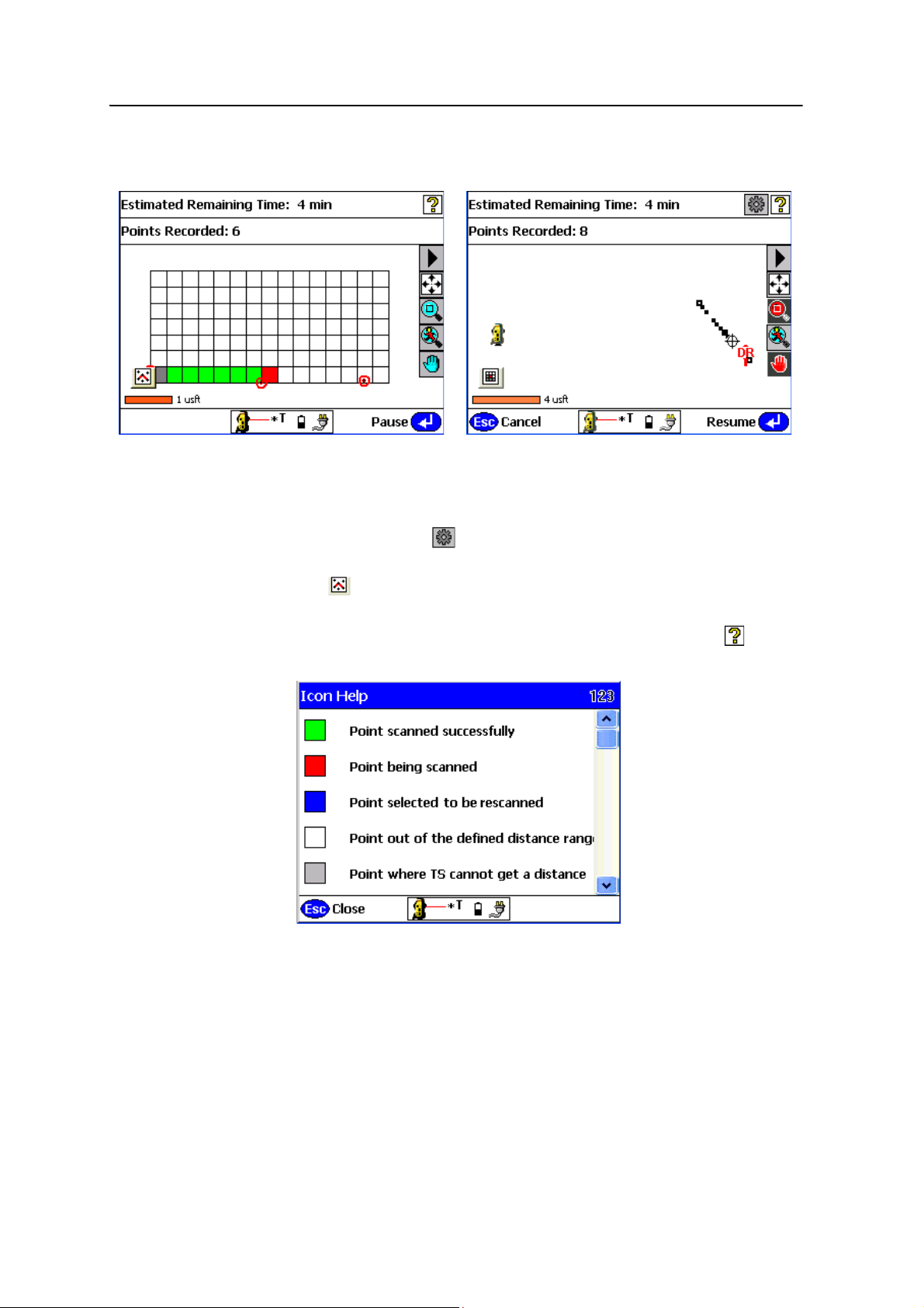
9 Advanced Features
12. Either tap Esc to go back and change any settings before starting the scan or tap
Start to start the scan.
A grid is displayed as the scan proceeds:
– Scan time remaining is displayed in the Estimated Time Remaining field.
– If you need to change the minimum and maximum distance settings tap
Pause and then tap . Change the minimum and maximum settings and
then tap
Next. The scan will resume.
– Tap in the lower left to display the map view so you can see the points
being collected.
– To obtain an explanation of the different grid sector colors, tap in the
upper right of the screen:
78 SCS900 Site Controller Software Total Station User Guide
Page 81
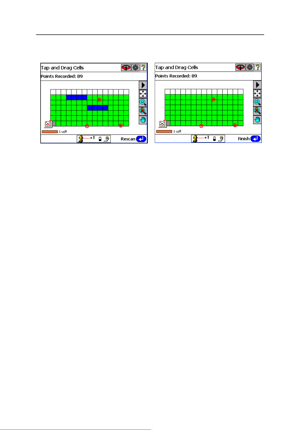
Advanced Features 9
13. Once scanning is complete, the Points Recorded field reports how many points
were collected:
14. To rescan any cells tap
OK to return to the measured cells display. Tap the
associated grid sectors with your stylus. Selected sectors turn blue. Once the
selection is made, tap
satisfactory and then tap
Rescan. Repeat the rescan function until results are
Finish.
SCS900 Site Controller Software Total Station User Guide 79
Page 82
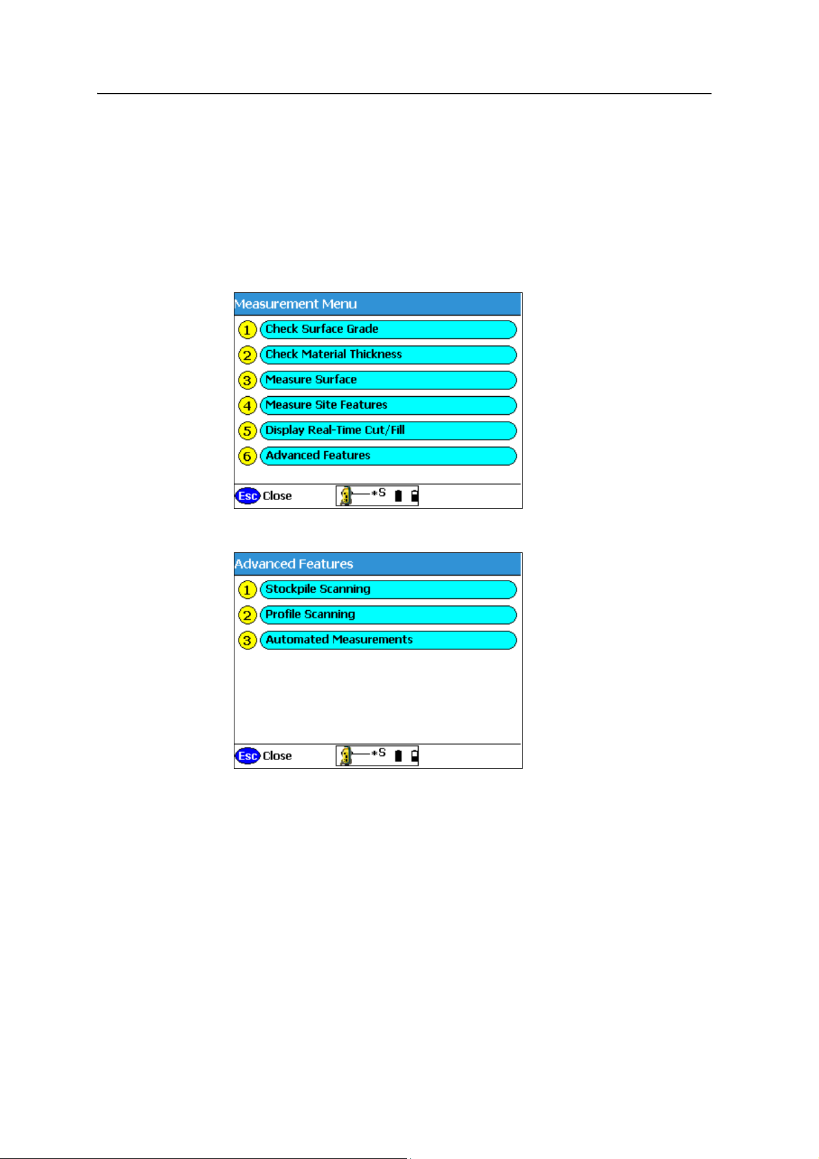
9 Advanced Features
Profile scan
The Profile Scan collects very accurate profile lines of features like quarry walls, high
walls, and steep side slopes where deep cuts are designed in highway construction.
Using reflectorless technology the areas can be measured without sending staff to a
location that could be unstable or impossible to access.
To set up profile scanning:
1. From the main menu, select
2. Select
Advanced Features:
Measurements:
80 SCS900 Site Controller Software Total Station User Guide
Page 83
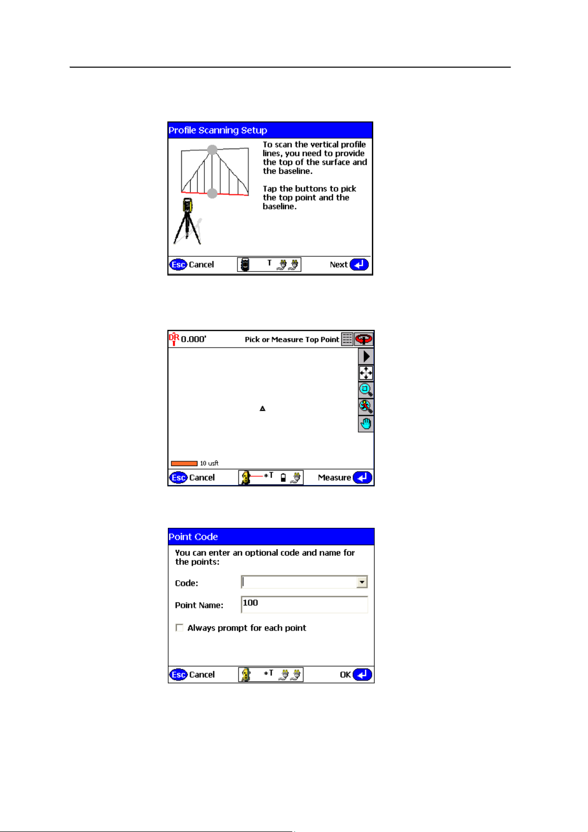
Advanced Features 9
3. Select Profile Scanning. The SCS900 software sets the instrument to DR Mode,
and then opens the following dialog:
4. Define the high point and the baseline of the wall or steep slope. Start by
tapping the gray dot at the highest point of the image on the screen. The map
view appears:
Manually sight your instrument to the highest point of the object being
measured and then tap
Measure. The following dialog appears:
SCS900 Site Controller Software Total Station User Guide 81
Page 84
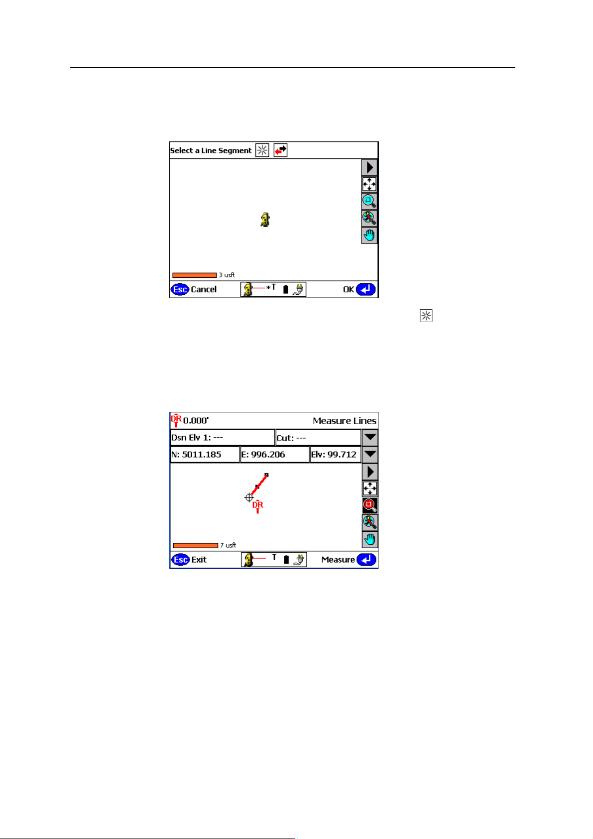
9 Advanced Features
5. You are then asked for an optional point code and point name. Enter values at
this screen and then tap
OK. The Profile Scanning Setup screen reappears.
6. Tap the bottom dot to define the baseline:
7. From the map view create a new line segment by tapping . At the prompt
enter a name for the line and then tap
OK. To define the baseline of the wall you
want to measure, point the instrument at any point of tangency on the base of
the wall so that the wall's base is accurately represented in the software. The
baseline can be defined by an irregular line made up of multiple points.
The line appears on the screen and you will hear a tone to indicate the line was
created succesfully:
82 SCS900 Site Controller Software Total Station User Guide
Page 85
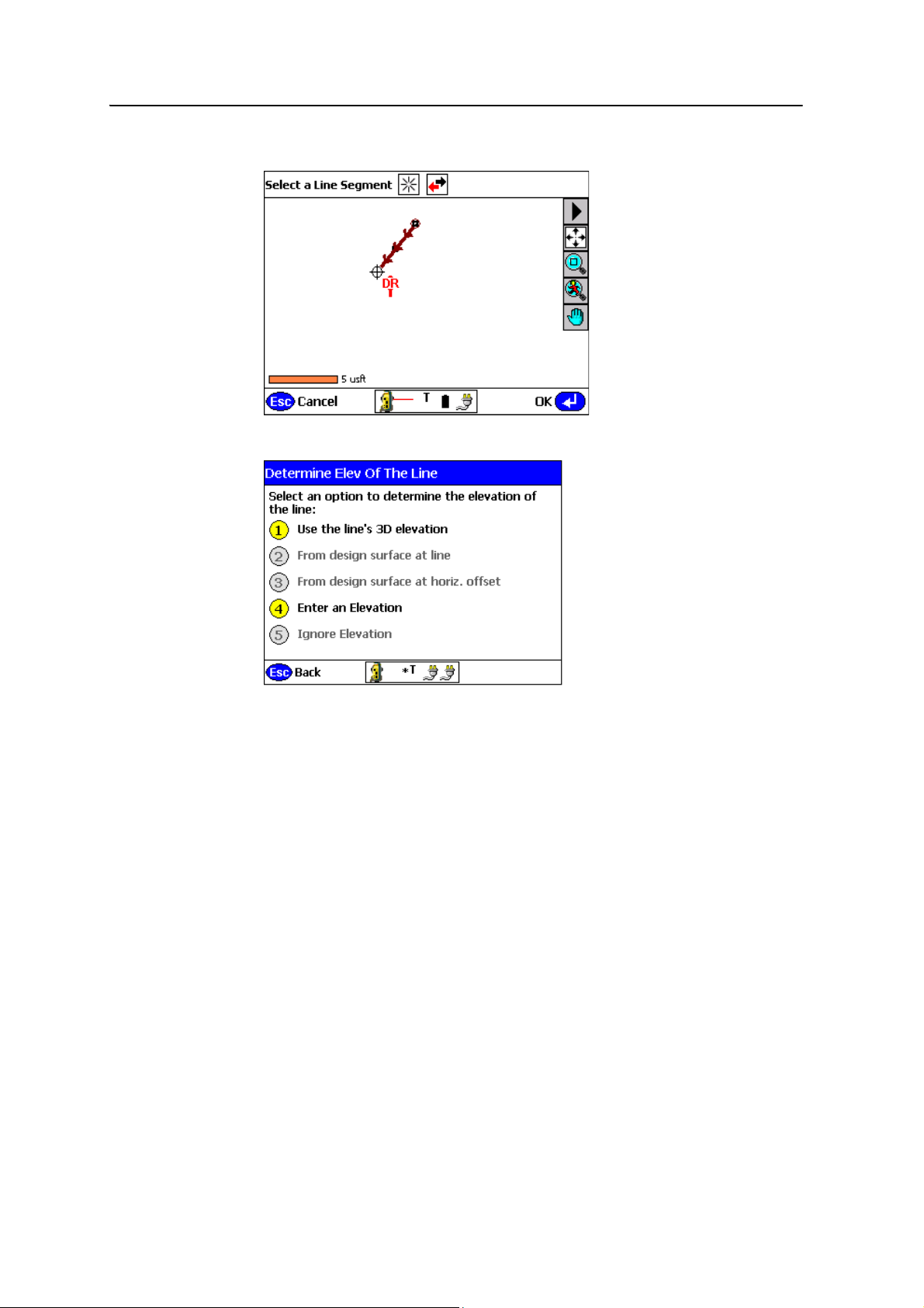
8. Tap Esc to go back to the profile scan:
Advanced Features 9
9. The line you just defined is already selected. Tap
OK:
10. Decide how to determine the 3D elevation of the line. Either:
– Select Use the line’s 3D elevation to use the lines current elevation.
– Select Enter an elevation to manually enter an elevation and then tap OK.
SCS900 Site Controller Software Total Station User Guide 83
Page 86
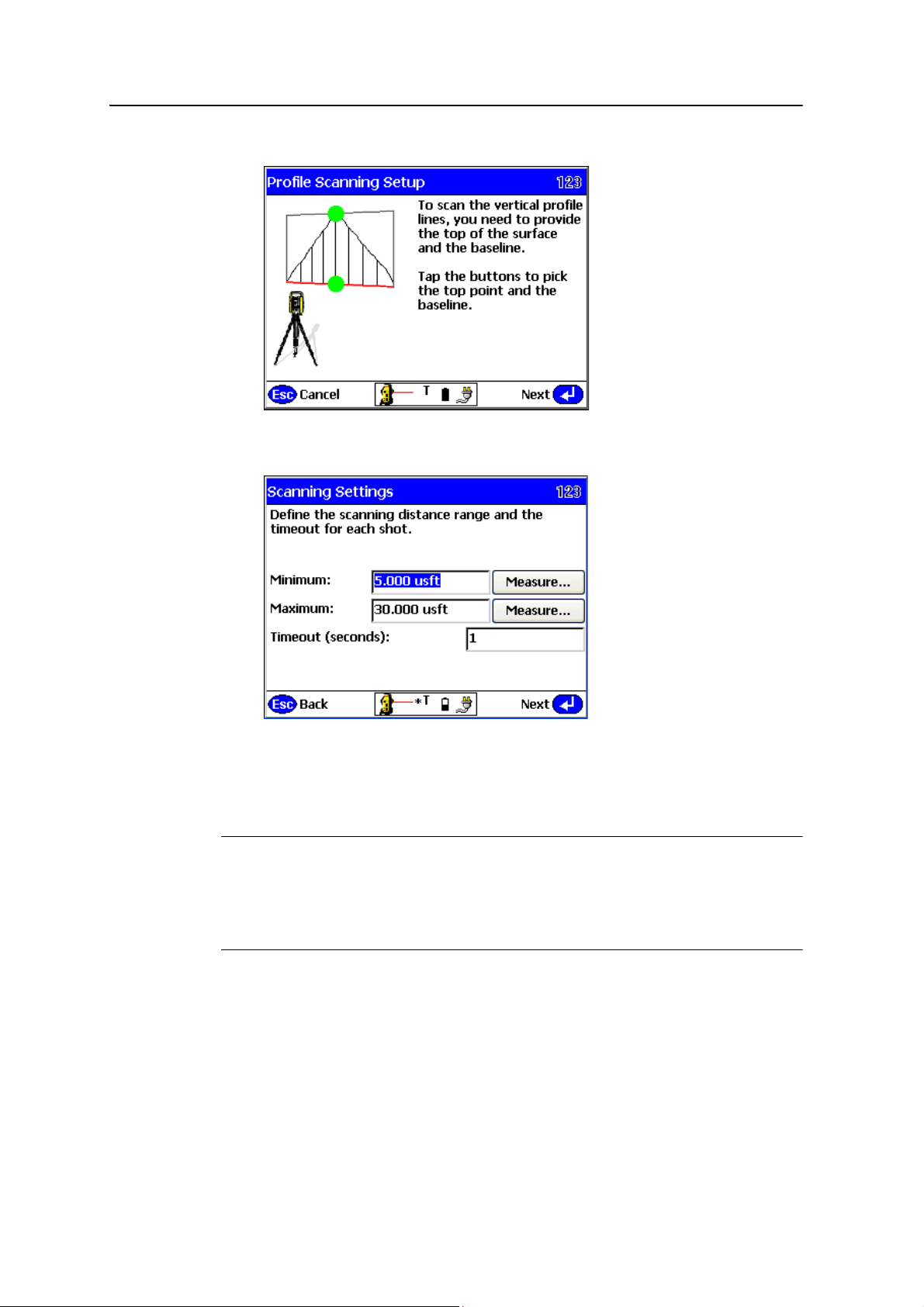
9 Advanced Features
11. The shape of the object you are scanning is now defined. The color of the dots
marking the top and bottom are now green. Tap
Next:
12. Define your minimum and maximum distances and then tap
of these settings will help you collect only relevant points in the field. The
software will default to the recommended Timeout value depending on which
instrument is being used.
C
B
84 SCS900 Site Controller Software Total Station User Guide
CAUTION – The values stored in Step 9 are overwritten by the min/max values set in the
DR Target Settings dialog (Chapter 14, Other Total Station Settings and Functions). Ensure
that you check the values set in the DR Target Settings dialog to eliminate confusion by
another operator when they are setting the Profile Scan settings. Setting the minimum
distance to 2 meters (6.56 feet) and maximum distance to 300 meters (984 feet) in the DR
Target Settings dialog will eliminate any errors when setting the Profile Scan settings.
Tip – When working at the maximum ranges of the DR technology the Timeout Setting
should be increased. When adjusting the timeout settings, be aware the material being
measured affects the strength of the response signal. Also, the instrument's technology
will affect the time it takes to record each individual point.
Next. Proper use
Page 87
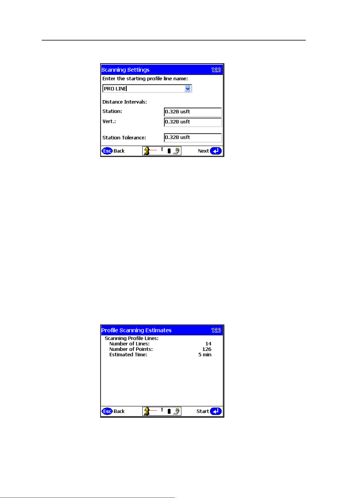
Advanced Features 9
13. Enter a profile line name and set the distance intervals:
– Defining the Station value determines how many profile lines you have
once the scan is complete. For example, if your baseline length is 10 meters
(~33 feet) and the Station Interval is set at 1 meter, you will have 10 profile
lines when the scan is finished. A shorter station interval results in more
profile lines, and the scan will take more time to complete.
B
– The Verti cal value determines how many points vertically you record along
each profile line. A flat surface requires fewer vertical points, an uneven
surface requires more. Enter a larger variable for flat surfaces, a smaller
variable for uneven surfaces.
– The Station Tolerance field defines how close to the projected profile line
each point is recorded. With the Station Tolerance set to .1 meter the
instrument continually adjusts as it scans each profile line until every point
collected is within ± .1 meter of the line.
14. Tap
Tip – The Profile Scan routine can be used for performing as-builts of side slopes. Defining
the high point and baseline of the side slope, and then setting the station tolerance to a
very loose value will create profile lines that are not true vertical and will give a very good
representation of a side slope.
Next.
SCS900 Site Controller Software Total Station User Guide 85
Page 88
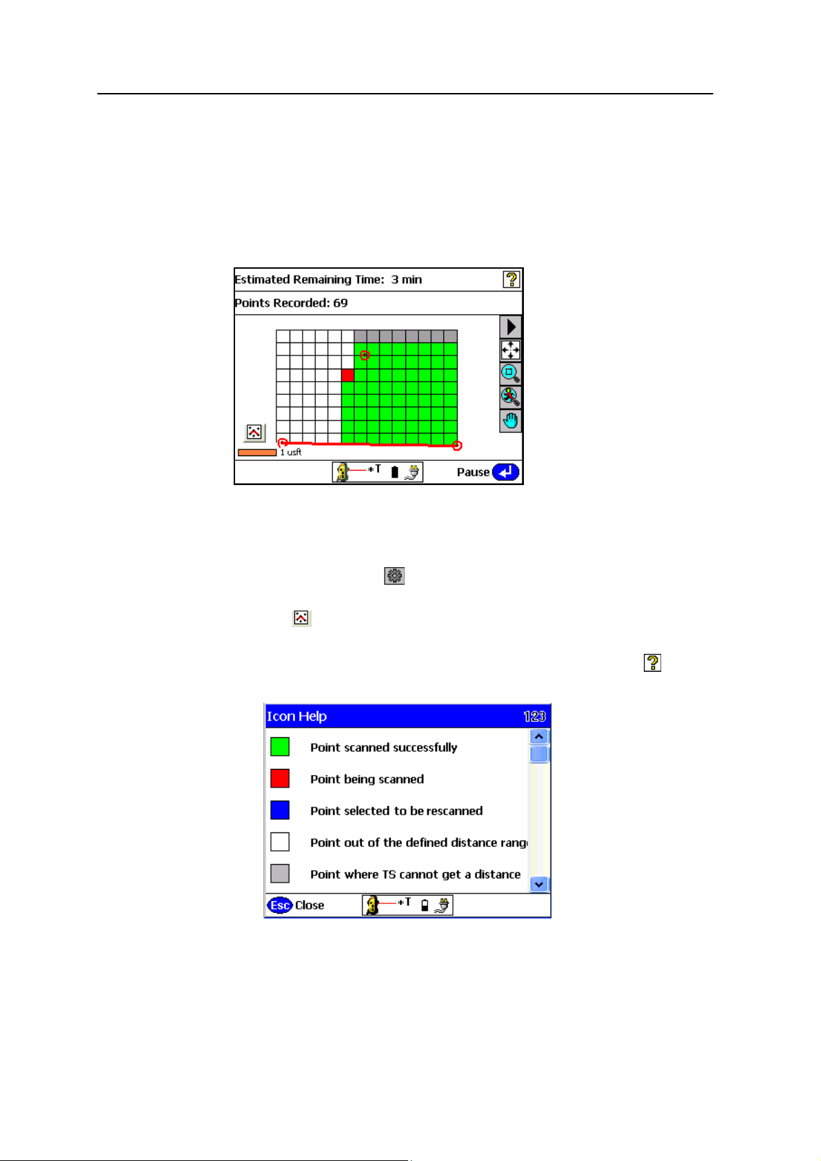
9 Advanced Features
15. The Profile Scanning Estimates screen displays the total number of lines and
points to be collected as a result of the dimensions and distance intervals
previously entered and the time it will take to record the points. This time is an
estimate only and the reflectivity of the material, distances involved, and type of
instrument used will alter the total time once the scan has started.
16. Either tap
Start to start the scan.
Esc to go back and alter any settings before starting the scan or tap
17. A grid is displayed as the scan proceeds:
– Scan time remaining is displayed in the Estimated Time Remaining field.
– If you need to change the minimum and maximum distance settings tap
Pause and then tap . Change the minimum and maximum settings and
then tap
– Tap in the lower left to display the map view so you can see the points
Next.
being collected.
– To obtain an explanation of the different grid sector colors, tap in the
upper right of the screen:
86 SCS900 Site Controller Software Total Station User Guide
Page 89
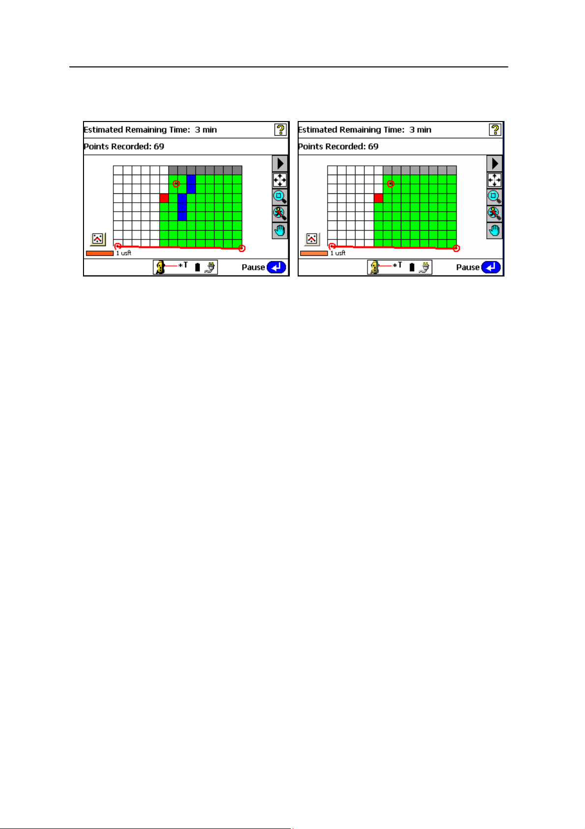
Advanced Features 9
18. Once scanning is complete the Points Recorded field reports how many points
were collected.
19. To rescan any cells tap
associated grid sectors with your stylus. Selected sectors will turn blue. Once the
selection is made tap
satisfactory and then tap
20. Once the scan results are satisfactory, tap
Automated measurement
Automated measurement with total stations is a useful tool for many applications
where the specifications of the project require that certain objects such as retaining
walls, bridge sections, or fly walls are continually measured over a defined period of
time to make sure that they do not move. This enables you to set up a total station, set
out some targets on the object you want to watch for movement, and then leave the
system to observe the object.
If you also use the built-in email capabilities, the system emails you if pre-defined
tolerances are exceeded. You can also enable other notifications such as a low battery
warning.
This frees you to work on other site tasks, and eliminates the need for you to manually
sight the instrument at each target you want to measure.
To setup Advanced Measurement:
OK to return to the measured cells display. Tap the
Rescan. Repeat the rescan function until results are
Finish.
Finish.
1. Establish the total station establishment as normal—either Known Station or
Arbitrary Location. See Chapter 6, Establishing the Position and Orientation of
the Total Station on the Jobsite (Station Establishment).
2. From the main menu, select (2) Measurements
SCS900 Site Controller Software Total Station User Guide 87
Page 90
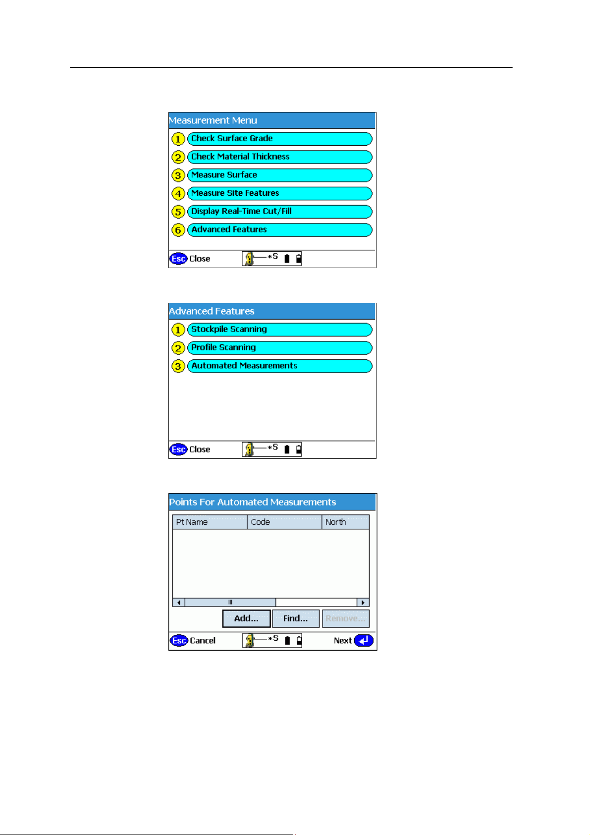
9 Advanced Features
3. Select (6) Advanced Features:
4. Select (3) Automated Measurements:
5. When prompted, select the points to measure and then tap
B
88 SCS900 Site Controller Software Total Station User Guide
Tip – At this time, set up the targets or prisms used to measure object movement. This
reduces the time needed to measure the prisms locations the first time, as you can remain
at the instrument and then simply turn it to each target and record its location.
Add:
Page 91
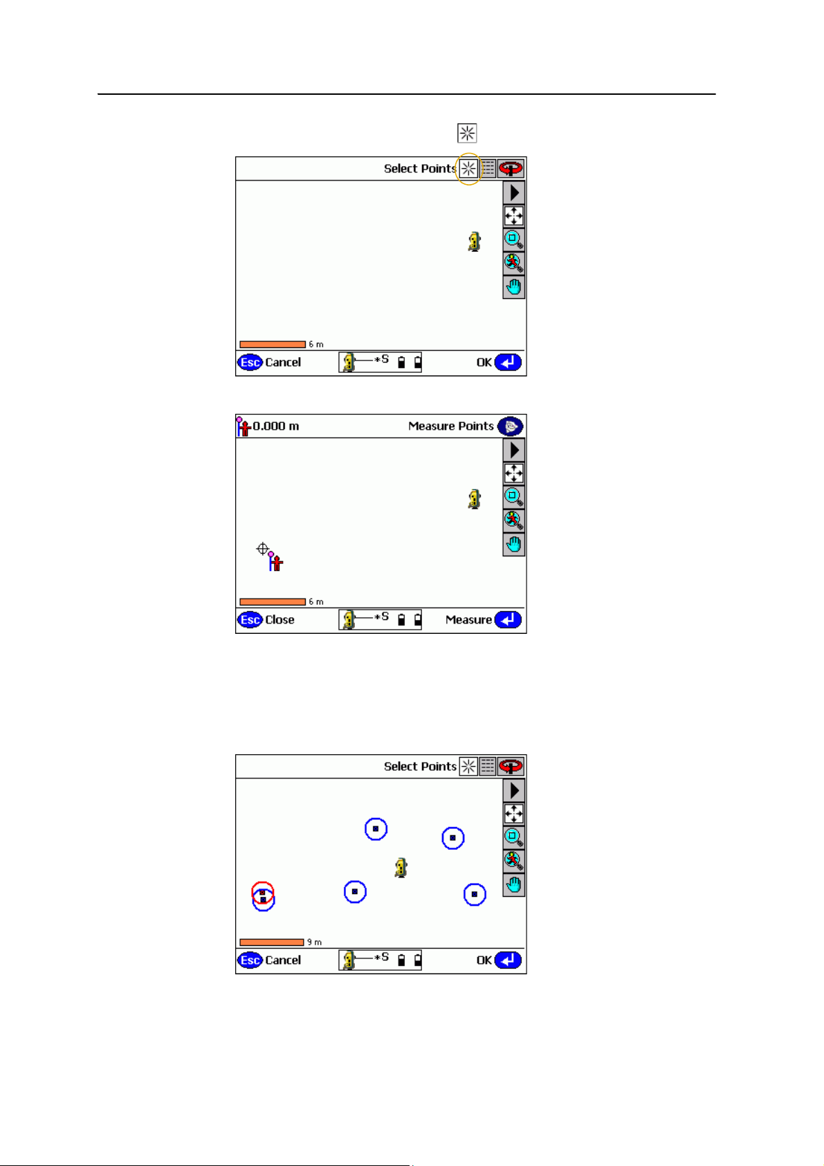
6. At the map screen, tap the New icon :
Advanced Features 9
7. Once the total station is locked to the target, tap
Measure:
8. Code the point and name it according to your company's conventions. Tap
9. Repeat step 7 and step 8 until you record all the required targets.
10. Once finished, tap
Esc from the Measure Points screen. The screen that appears
shows the measured points:
OK.
SCS900 Site Controller Software Total Station User Guide 89
Page 92
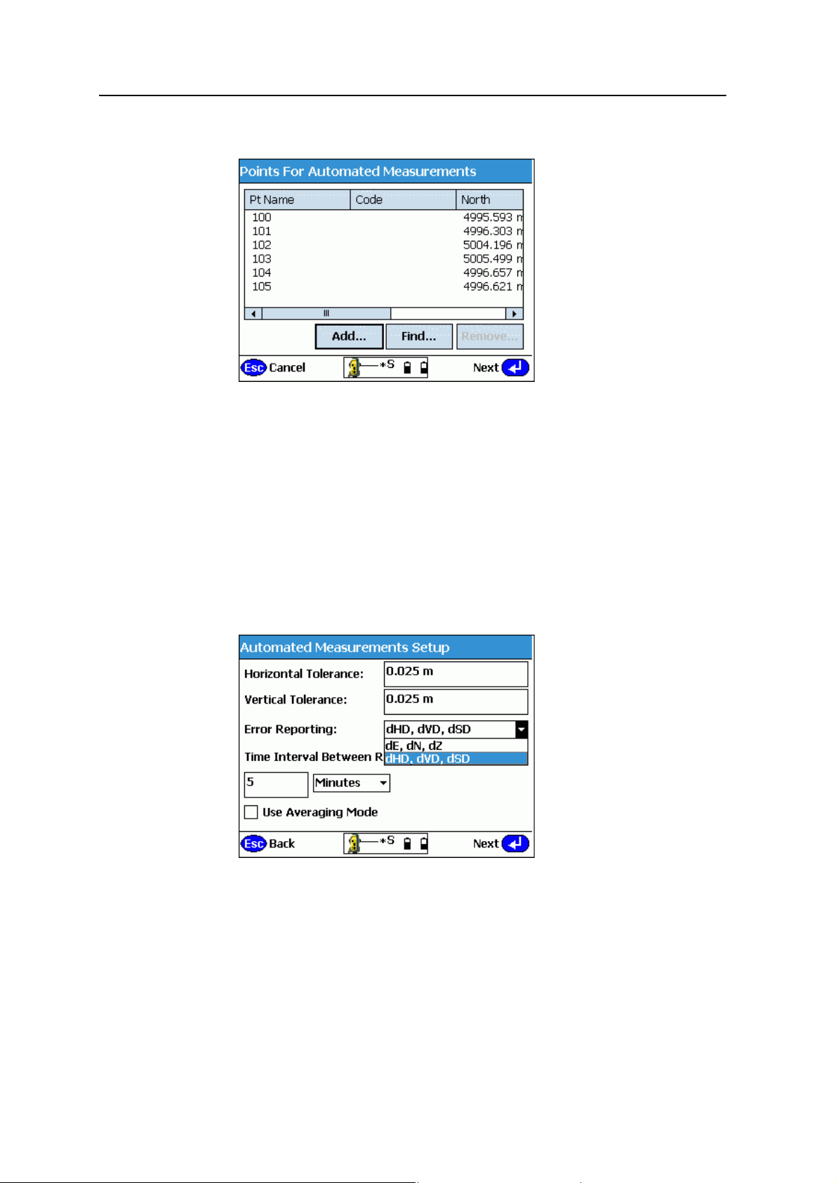
9 Advanced Features
11. Tap OK and then tap Next in the dialog that appears:
12. In the dialog that appears, do the following:
a. Set the tolerances. The Horizontal Tolerance and Vertical Tolerance relate
to the allowable threshold before the software reports that a point is out of
tolerance.
b. Set error reporting as ΔHD, ΔVD, ΔSD or as ΔE, ΔN, ΔZ.
c. To set the time between rounds of measurement, enter a number and then
select either minutes or hours from the drop-down list.
d. If required, select the Averaging Mode check box, which results in a more
accurate point measurement. See Averaging mode, page 124.
e. Tap
Next:
13. In the dialog that appears, do the following:
a. Enter your email address.
b. Select to be emailed when there is an error (a measured point lies outside
tolerances), or for a general progress report.
c. Set the frequency for receiving a progress report.
90 SCS900 Site Controller Software Total Station User Guide
Page 93
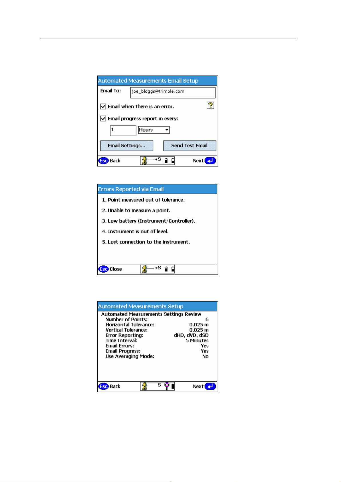
d. If not already done so, configure the email settings.
Advanced Features 9
B
e. Tap
Tip – For an explanation of the error reports you will receive, tap the question mark:
Next:
The Internet connection is tested for you; once verified, the summary screen
appears. Tap
Next:
SCS900 Site Controller Software Total Station User Guide 91
Page 94
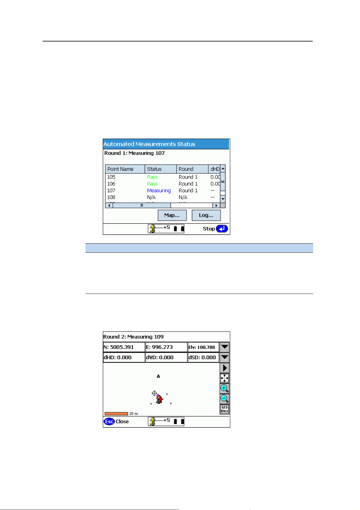
9 Advanced Features
Note – The default target type for standing mode is where you define the target type you
used for the targets you mounted to the object to be monitored. You must use the same
target type for each point. Otherwise, the prism constant applied to some points will not be
correct and the resulting data is unreliable.
14. When prompted in the dialog that appears, select the default target height and
type for standing mode and then tap
Next.
The total station now starts to automatically measure to each point you
recorded earlier, at the time interval and with the tolerances you set up. A status
screen shows the following information:
Column Information
1 Point name
2 Point status
3 Number of the last round completed
4-6 Changes from the original measured value in HD, VD, and SD (as
specified during the setup)
15. Tap
Map to open a screen that shows a plan view of the points and the total
station position, as well as changes from the originally stored values for the
point at which the instrument is currently aimed:
92 SCS900 Site Controller Software Total Station User Guide
Page 95
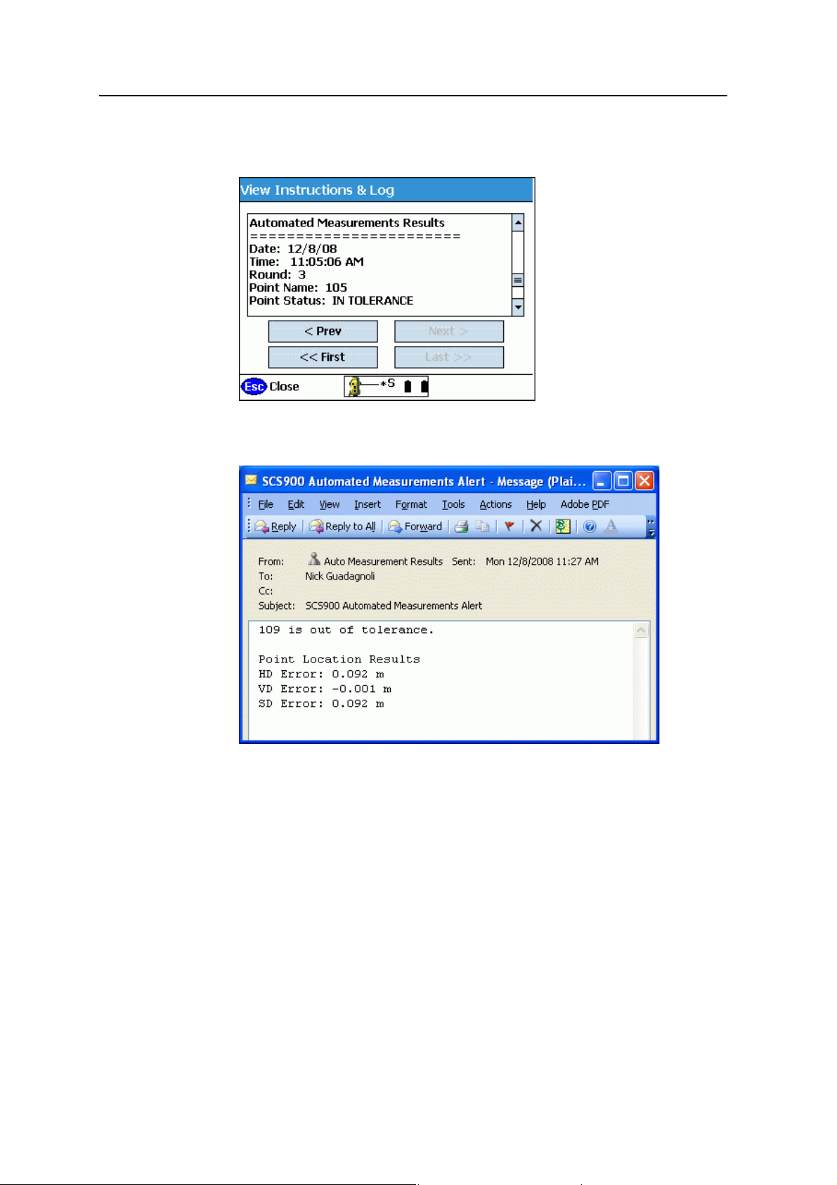
Advanced Features 9
16. Tap Log to open a screen that shows a list of actions that occurred on that data
collector, as well as results of each round of automated measurements:
If a measured point does not meet the specified tolerances, the system notifies
you by email that the point has moved:
SCS900 Site Controller Software Total Station User Guide 93
Page 96
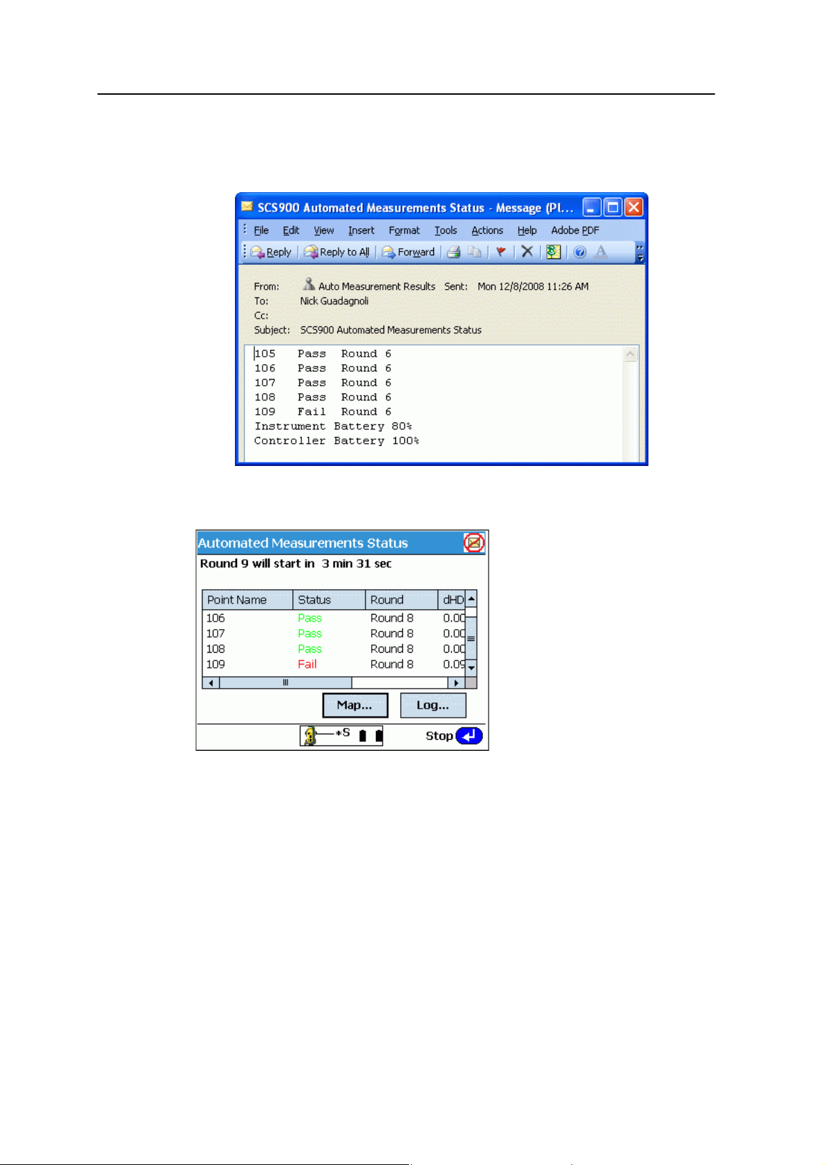
9 Advanced Features
If you chose to receive a progress report, that is also emailed at the selected
interval, and includes the battery life of the data collector and the instrument.
This assists you to plan when to change the batteries:
Note – If the system failed to send an email, the progress screen shows an icon in the upper
right of the screen. Once an email is successfully sent, this icon disappears:
94 SCS900 Site Controller Software Total Station User Guide
Page 97
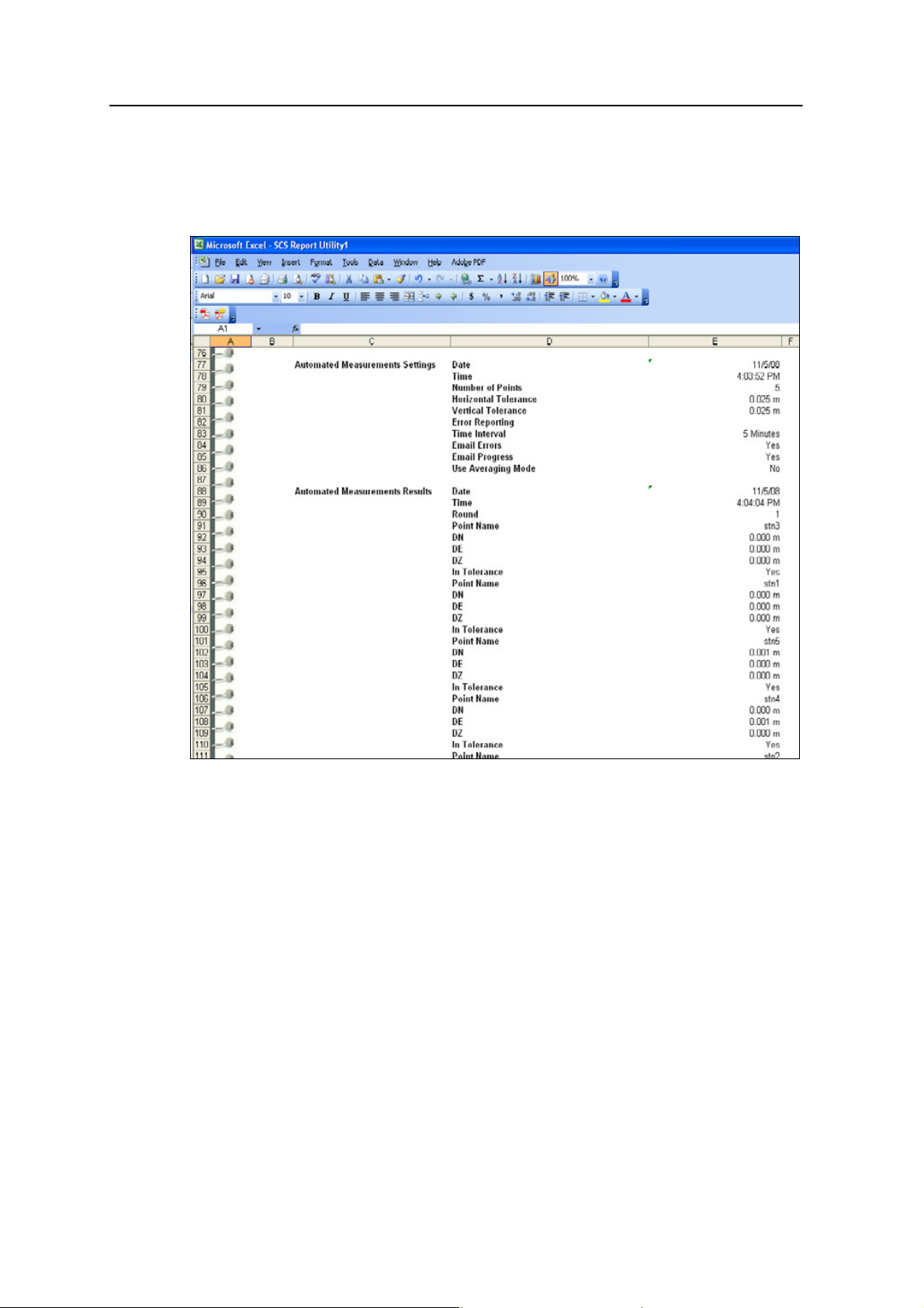
Advanced Features 9
Once you finish watching the points for the intended time period, you can synchronize
your data collector with your laptop and then view the Report.txt file in the SCS
Report utility. You can save this concise record of the measured points as an Excel
spreadsheet file for delivery to the project authority:
SCS900 Site Controller Software Total Station User Guide 95
Page 98

9 Advanced Features
96 SCS900 Site Controller Software Total Station User Guide
Page 99

CHAPTER
10
Setting up the Total Station for Robotic Operation
In this chapter:
Starting with the controller
connected directly to the total
station
Starting with the controller
connected over the radio to the
total station
10
When working in Robotic mode, the total station
is connected to the controller using the
integrated radio.
You can start the system in Robotic mode in two
ways:
• with the controller connected directly to
the total station
• with the controller connected over the
radio to the total station
SCS900 Site Controller Software Total Station User Guide 97
Page 100

10 Setting up the Total Station for Robotic Operation
Starting with the controller connected directly to the total station
In this method, you first connect the controller to the total station, follow the
procedure outlined below, then move the controller to the rod and reconnect to the
total station over the radio. This method is typically used at one of the following times:
• When the station position and orientation needs establishing first, while at the
total station position using the total station as a Servo, Autolock, or
Reflectorless system, before starting robotic operation
• When the instrument station is used for machine control operation (ATS and
SPSx30 only)
You can carry out station establishment for robotic operation either while at the total
station, or after the total station has been put into Robotic mode from the rod. In
either case, the station establishment process described in Chapter 6, Establishing the
Position and Orientation of the Total Station on the Jobsite (Station Establishment) is
the same.
This method of operation involves the following basic steps:
1. Set up and level the total station.
B
2. Switch on the total station and the controller.
Tip – When a Trimble CU controller is connected directly to the total station, it will also
power on when the total station is turned on.
Note – If the SCS900 software was last used in GPS mode, it will not automatically detect
the total station. Select
System Setup / Switch to Total Station Setup to automatically
dectect it.
3. Start the SCS900 software and allow the controller to make the connection with
the total station:
– For the ATS and 5600 total stations, the controller is connected through a
cable (TSC2) or through the keyboard attachment plate (ACU).
– For an SPSx10, SPS700, or SPSx30 total station, when connected through a
cable (TSC2) or the keyboard attachment plate (Trimble CU), the controller
automatically connects to the total station. However, if you use Bluetooth
wireless technology (TSC2) to connect to the total station, you will need to
force the connection to the total station (select
Instrument /
Connect via Bluetooth).
System Setup / Connect
Note – If the SCS900 software was last used in GPS mode, it will not automatically detect
the total station. Select
System Setup / Switch to Total Station Setup to automatically
dectect it.
4. Once connected, fine level the total station. See page 13.
5. Initiate the compensator (ATS and 5605 total stations only). See page 12.
6. Set the atmospheric corrections. See page 14.
98 SCS900 Site Controller Software Total Station User Guide
 Loading...