

Page 1

USER GUIDE
Trimble R8s GNSS Receiver
Version 1.00
Revision C
February 2016
1
Page 2
Corporate Office
Trimble Navigation Limited
Engineering and Construction group
5475 Kellenburger Road
Dayton, Ohio 45424-1099
USA
800-538-7800 (toll free in USA)
+1-937-245-5600 Phone
+1-937-233-9004 Fax
Geospatial Division
Trimble Navigation Limited
Geospatial Division
10368 Westmoor Drive
Westminster, CO 80021
USA
www.trimble.com
Email: trimble_support@trimble.com
Legal Notices
© 2016, Trimble Navigation Limited. All rights reserved.Trimble, the
Globe & Triangle logo, BlueCap, GPS Total Station, Recon, and TSC2 are
trademarks of Trimble Navigation Limited, registered in the United
States and in other countries. Access, CMR+, Digital Fieldbook, Maxwell,
Trimble Geomatics Office, Trimble Survey Controller, TRIMMARK,
TRIMTALK, and TSCe are trademarks of Trimble Navigation Limited. The
Bluetooth word mark and logos are owned by the Bluetooth SIG, Inc.
and any use of such marks by Trimble Navigation Limited is under
license. Microsoft, Windows, and Windows NT are either registered
trademarks or trademarks of Microsoft Corporation in the United States
and/or other countries. All other trademarks are the property of their
respective owners.
Release Notice
This is the February 2016 release (Revision C) of the Trimble R8s GNSS
receiver documentation.
Product Limited Warranty Information
For applicable product Limited Warranty information, please refer to the
Limited Warranty Card included with this Trimble product, or consult your
local Trimble authorized dealer.
Notices
Class B Statement – Notice to Users. This equipment has been
tested and found to comply with the limits for a Class B digital device,
pursuant to Part 15 of the FCC rules and Part 90. These limits are
designed to provide reasonable protection against harmful interference
in a residential installation. This equipment generates, uses, and can
radiate radio frequency energy and, if not installed and used in
accordance with the instructions, may cause harmful interference to
radio communication. However, there is no guarantee that interference
will not occur in a particular installation. If this equipment does cause
harmful interference to radio or television reception, which can be
determined by turning the equipment off and on, the user is encouraged
to try to correct the interference by one or more of the following
measures:
– Reorient or relocate the receiving antenna.
– Increase the separation between the equipment and the receiver.
– Connect the equipment into an outlet on a circuit different from that to
which the receiver is connected.
– Consult the dealer or an experienced radio/TV technician for help.
Changes and modifications not expressly approved by the manufacturer
or registrant of this equipment can void your authority to operate this
equipment under Federal Communications Commission rules.
Canada
This digital apparatus does not exceed the Class B limits for radio noise
emissions from digital apparatus as set out in the radio interference
regulations of the Canadian Department of Communications. This
Category II radiocommunication device complies with Industry Canada
Standard RSS-310.
Le présent appareil numérique n’émet pas de bruits radioélectriques
dépassant les limites applicables aux appareils numériques de Classe B
prescrites dans le règlement sur le brouillage radioélectrique édicté par
le Ministère des Communications du Canada. Ce dispositif de
radiocommunication de catégorie II respecte la norme CNR-310
d’Industrie Canada.
Europe
This product has been tested and found
to comply with the essential
requirements for a Class B device
pursuant to European Council Directive
1999/5/EC on R&TTE on EMC, thereby satisfying the requirements for
CE Marking and sale within the European Economic Area (EEA). These
requirements are designed to provide reasonable protection against
harmful interference when the equipment is operated in a residential or
commercial environment. The 450 MHz band is not harmonised across
the European Community..
Australia and New Zealand
This product conforms with the regulatory
requirements of the Australian Communications
and Media Authority (ACMA) EMC framework,
thus satisfying the requirements for RCM
marking and sale within Australia and New
Zealand.
Taiwan – Battery Recycling Requirements
The product contains a removable Lithium-ion battery. Taiwanese
regulations require that waste batteries are recycled.
廢電池 請 回 收
Brazil
Este produto está homologado pela ANATEL, de acordo com
os procedimentos regulamentados pela Resolução 242/2000,
e atende aos requisitos técnicos aplicados.
Este equipamento opera em caráter secundário, isto é, não
tem direito a proteção contra interferências prejudicial,
mesmo de estações do mesmo tipo, e não pode causar
interferência a sistemas operando em caráter primário.
Para maiores informações, consulte o site da ANATEL
www.anatel.gov.br.
Modelo CBSMA-110A
0757-13-6140
Waste Electrical and Electronic Equipment (WEEE)
For product recycling instructions and more information,
please go to www.trimble.com/ev.shtml.
Recycling in Europe: To recycle Trimble WEEE (Waste
Electrical and Electronic Equipment, products that run on
electrical power.), Call +31 497 53 24 30, and ask for the
“WEEE Associate”. Or, mail a request for recycling instructions to:
Trimble Europe BV
c/o Menlo Worldwide Logistics
Meerheide 45
5521 DZ Eersel, NL
Trimble R8s GNSS Receiver User Guide 2
Page 3

FCC Declaration of Conformity
We, Trimble Navigation Limited.
935 Stewart Drive
PO Box 3642
Sunnyvale, CA 94088-3642
United States
+1-408-481-8000
Declare under sole responsibility that DoC products comply
with Part 15 of FCC Rules.
Operation is subject to the following two conditions:
(1) This device may not cause harmful interference, and
(2) This device must accept any interference received,
including interference that may cause undesired operation
RTTE Compliance statements
Czech Trimble Navigation Limited tímto prohlašuje, že
tento (Trimble R8s Model 1 GNSS) je ve shodě se
základními požadavky a dalšími příslušnými
ustanoveními směrnice 1999/5/ES.
Danish Undertegnede Trimble Navigation Limited erklærer
herved, at følgende udstyr (Trimble R8s Model 1
GNSS) overholder de væsentlige krav og øvrige
relevante krav i direktiv 1999/5/EF.
Dutch Hierbij verklaart Trimble Navigation Limited dat het
toestel (Trimble R8s Model 1 GNSS) in
overeenstemming is met de essentiële eisen en de
andere relevante bepalingen van richtlijn
1999/5/EG.
English Hereby, Trimble Navigation Limited, declares that
this equipment (Trimble R8s Model 1 GNSS) is in
compliance with the essential requirements and
other relevant provisions of Directive 1999/5/EC.
Estonian Käesolevaga kinnitab Trimble Navigation Limited
seadme (Trimble R8s Model 1 GNSS) vastavust
direktiivi 1999/5/EÜ põhinõuetele ja nimetatud
direktiivist tulenevatele teistele asjakohastele
sätetele.
German Hiermit erklärt Trimble Navigation Limited, dass
sich das Gerät (Trimble R8s Model 1 GNSS) in
Übereinstimmung mit den grundlegenden
Anforderungen und den übrigen einschlägigen
Bestimmungen der Richtlinie 1999/5/EG befindet.
Greek ΜΕ ΤΗΝ ΠΑΡΟΥΣΑ Trimble Navigation Limited
ΔΗΛΩΝΕΙ ΟΤΙ (Trimble R8s Model 1 GNSS)
ΣΥΜΜΟΡΦΩΝΕΤΑΙ ΠΡΟΣ ΤΙΣ ΟΥΣΙΩΔΕΙΣ
ΑΠΑΙΤΗΣΕΙΣ ΚΑΙ ΤΙΣ ΛΟΙΠΕΣ ΣΧΕΤΙΚΕΣ ΔΙΑΤΑΞΕΙΣ
ΤΗΣ ΟΔΗΓΙΑΣ 1999/5/ΕΚ.
Hungarian Alulírott, Trimble Navigation Limited nyilatkozom,
hogy a (Trimble R8s Model 1 GNSS) megfelel a
vonatkozó alapvetõ követelményeknek és az
1999/5/EC irányelv egyéb elõírásainak.
Finnish Trimble Navigation Limited vakuuttaa täten että
(Trimble R8s Model 1 GNSS) tyyppinen laite on
direktiivin 1999/5/EY oleellisten vaatimusten ja sitä
koskevien direktiivin muiden ehtojen mukainen.
Icelandic Hér með lýsir Trimble Navigation Limited yfir því að
(Trimble R8s Model 1 GNSS) er í samræmi við
grunnkröfur og aðrar kröfur, sem gerðar eru í
tilskipun 1999/5/EC.
Italian Con la presente Trimble Navigation Limited dichiara
che questo (Trimble R8s Model 1 GNSS) è conforme
ai requisiti essenziali ed alle altre disposizioni
pertinenti stabilite dalla direttiva 1999/5/CE.
Latvian Ar šo Trimble Navigation Limited deklarē, ka
(Trimble R8s Model 1 GNSS) atbilst Direktīvas
1999/5/EK būtiskajām prasībām un citiem ar to
saistītajiem noteikumiem.
Lithuanian Šiuo Trimble Navigation Limited deklaruoja, kad šis
(Trimble R8s Model 1 GNSS) atitinka esminius
reikalavimus ir kitas 1999/5/EB Direktyvos
nuostatas.
Maltese Hawnhekk, Trimble Navigation Limited, jiddikjara li
dan (Trimble R8s Model 1 GNSS) jikkonforma malħtiġijiet essenzjali u ma provvedimenti oħrajn
relevanti li hemm fid-Dirrettiva 1999/5/EC.
Norwegian Trimble Navigation Limited erklærer herved at
utstyret (Trimble R8s Model 1 GNSS) i samsvar
med de grunnleggende krav og øvrige relevante
krav i direktiv 1999/5/EF.
Polish Niniejszym Trimble Navigation Limited oświadcza,
że (Trimble R8s Model 1 GNSS) jest zgodny z
zasadniczymi wymogami oraz pozostałymi
stosownymi postanowieniami Dyrektywy
1999/5/EC.
Portuguese Trimble Navigation Limited declara que este
(Trimble R8s Model 1 GNSS) está conforme com os
requisitos essenciais e outras disposições da
Directiva 1999/5/CE.
Slovak Trimble Navigation Limited týmto vyhlasuje, že
(Trimble R8s Model 1 GNSS) spĺňa základné
požiadavky a všetky príslušné ustanovenia
Smernice 1999/5/ES.
Slovenian Trimble Navigation Limited izjavlja, da je ta (Trimble
R8s Model 1 GNSS) skladu z bistvenimi zahtevami
in ostalimi relevantnimi določili direktive
1999/5/ES.
Spanish Por medio de la presente Trimble Navigation
Limited declara que el (Trimble R8s Model 1 GNSS)
cumple con los requisitos esenciales y cualesquiera
otras disposiciones aplicables o exigibles de la
Directiva 1999/5/CE.
Swedish Härmed intygar Trimble Navigation Limited att
denna (Trimble R8s Model 1 GNSS) står I
överensstämmelse med de väsentliga
egenskapskrav och övriga relevanta bestämmelser
som framgår av direktiv 1999/5/EG.
French Par la présente Trimble Navigation Limited déclare
que l'appareil (Trimble R8s Model 1 GNSS) est
conforme aux exigences essentielles et aux autres
dispositions pertinentes de la directive 1999/5/CE.
Trimble R8s GNSS Receiver User Guide 3
Page 4
Safety Information
Before you use your Trimble product, make sure that you have read and understood all safety
requirements.
WARNING – This alert warns of a potential hazard which, if not avoided, could result in severe injury or even
death.
CAUTION – This alert warns of a potential hazard or unsafe practice that could result in minor injury or
property damage or irretrievable data loss.
Note – An absence of specific alerts does not mean that there are no safety risks involved.
Regulations and safety
The receivers contain integral Bluetooth® wireless technology, and may also send radio signals
through the antenna of an internal radio-modem, or through an externally-connected data
communications radio. Regulations regarding the use of the 450 MHz radio-modems vary greatly
from country to country. In some countries, the unit can be used without obtaining an end-user
license. Other countries require end-user licensing. For licensing information, consult your local
Trimble distribution partner. Bluetooth operates in license-free bands.
Use and Care
This product is designed to withstand the rough treatment and tough environment that typically
occurs in construction applications. However, the receiver is a high-precision electronic instrument
and should be treated with reasonable care.
CAUTION – Operating or storing the receiver outside the specified temperature range can damage it.
Type approval
Type approval, or acceptance, covers technical parameters of the equipment related to emissions
that can cause interference. Type approval is granted to the manufacturer of the transmission
equipment, independent from the operation or licensing of the units. Some countries have unique
technical requirements for operation in particular radio-modem frequency bands. To comply with
those requirements, Trimble may have modified your equipment to be granted type approval.
Unauthorized modification of the units voids the type approval, the warranty, and the operational
license of the equipment.
Trimble R8s GNSS Receiver User Guide 4
Page 5

Safety Information
Operation near other radio equipment
When operating the receiver in member states of the European Union and in other counties which
adhere to the EU R&TTE requirements, while in the vicinity of aeronautical radionavigation
equipment operating between 2700 and 2900 MHz, or Fixed, Fixed Satellite (space to Earth), or
Mobile systems operating at 4170 MHz, a minimum separation of 5 meters must be maintained
between the receiver and such radio equipment.
Exposure to radio frequency radiation
For 450 MHz radio
Safety. Exposure to RF energy is an important safety consideration. The FCC has adopted a safety
standard for human exposure to radio frequency electromagnetic energy emitted by FCC regulated
equipment as a result of its actions in General Docket 79-144 on March 13, 1986.
Proper use of this radio modem results in exposure below government limits. The following
precautions are recommended:
l
DO NOT operate the transmitter when someone is within 20 cm (7.8 inches) of the antenna.
l
DO NOT co-locate (place within 20 cm (7.8 inches)) the radio antenna with any other
transmitting antenna.
l
DO NOT operate the transmitter unless all RF connectors are secure and any open connectors
are properly terminated.
l
DO NOT operate the equipment near electrical blasting caps or in an explosive atmosphere.
l
All equipment must be properly grounded according to Trimble installation instructions for safe
operation.
l
All equipment should be serviced only by a qualified technician.
For GSM radio
For your own safety, and in terms of the RF Exposure requirements of the FCC, always observe the
precautions listed here.
l Always maintain a minimum separation distance of 20 cm (7.8 inches) between yourself and the
radiating antenna on the receiver radio modem.
l Do not collocate (place within 20 cm) the radio antenna with any other transmitting antenna
Note – The optional GSM radio cannot legally be operated in Brazil.
Trimble R8s GNSS Receiver User Guide 5
Page 6

Safety Information
For Bluetooth radio
The radiated output power of the internal Bluetooth wireless radio and the Wi-Fi radio included in
some Trimble receivers is far below the FCC radio frequency exposure limits. Nevertheless, the
wireless radio(s) shall be used in such a manner that the Trimble receiver is 20 cm or further from the
human body. The internal wireless radio(s) operate within guidelines found in radio frequency safety
standards and recommendations, which reflect the consensus of the scientific community. Trimble
therefore believes that the internal wireless radio(s) are safe for use by consumers. The level of
energy emitted is far less than the electromagnetic energy emitted by wireless devices such as
mobile phones. However, the use of wireless radios may be restricted in some situations or
environments, such as on aircraft. If you are unsure of restrictions, you are encouraged to ask for
authorization before turning on the wireless radio.
Installing antennas
CAUTION – For your own safety, and in terms of the RF exposure requirements of the FCC, always observe
these precautions:
– Always maintain a minimum separation distance of cm ( inches) between yourself and the radiating antenna.
– Do not co-locate the antenna with any other transmitting device.
This device has been designed to operate with the antennas listed below.
UHF antennas not included in this list, or that have a gain greater than 5 dBi, are strictly prohibited
for use with this device. The required antenna impedance is 50 W..
The antennas that can be used (country dependent) with the 450 MHz radio are 0 dBi and 5 dBi whip
antennas.
The antenna that can be used with the GSM radio is the 0 dBi whip antenna.
To reduce potential radio interference to other users, the antenna type and its gain should be so
chosen that the equivalent isotropically radiated power (e.i.r.p.) is not more than that permitted for
successful communication.
Trimble R8s GNSS Receiver User Guide 6
Page 7
Safety Information
Lithium-ion Battery safety
WARNING – Charge and use the rechargeable Lithium-ion battery only in strict accordance with the
instructions. Charging or using the battery in unauthorized equipment can cause an explosion or fire, and can
result in personal injury and/or equipment damage.
To prevent injury or damage:
– Do not charge or use the battery if it appears to be damaged or leaking.
–Charge the Lithium-ion batteries only in a Trimble battery charger, such as the dual battery charger P/N 6111600 (black) or P/N 53018010 (grey), or the five-battery system charger P/N 49499-00 (yellow/grey) or another
charger specified for this battery. Be sure to follow all instructions that are provided with the battery charger.
– Discontinue charging a battery that gives off extreme heat or a burning odor.
– Use the battery only in Trimble equipment that is specified to use it.
– Use the battery only for its intended use and according to the instructions in the product documentation.
WARNING – Do not damage the rechargeable Lithium-ion battery. A damaged battery can cause an
explosion or fire, and can result in personal injury and/or property damage.
To prevent injury or damage:
– Do not use or charge the battery if it appears to be damaged. Signs of damage include, but are not limited to,
discoloration, warping, and leaking battery fluid.
– Do not expose the battery to fire, high temperature, or direct sunlight.
– Do not immerse the battery in water.
– Do not use or store the battery inside a vehicle during hot weather.
– Do not drop or puncture the battery.
– Do not open the battery or short-circuit its contacts.
WARNING – Avoid contact with the rechargeable Lithium-ion battery if it appears to be leaking. Battery fluid
is corrosive, and contact with it can result in personal injury and/or property damage.
To prevent injury or damage:
– If the battery leaks, avoid contact with the battery fluid.
– If battery fluid gets into your eyes, immediately rinse your eyes with clean water and seek medical attention.
Do not rub your eyes!
– If battery fluid gets onto your skin or clothing, immediately use clean water to wash off the battery fluid.
Trimble R8s GNSS Receiver User Guide 7
Page 8

Contents
Safety Information 4
Regulations and safety 4
Use and Care 4
Type approval 4
Operation near other radio equipment 5
Exposure to radio frequency radiation 5
Installing antennas 6
Lithium-ion Battery safety 7
Contents 8
1 Introduction 10
Overview 11
Use and care 11
COCOM limits 11
Related information 12
Technical support 12
2 Setting up the Receiver 13
Parts of the R8s receiver 14
External UHF or GSM antenna 16
Setup guidelines 16
Setting up the receiver on a range pole 17
Other system components 18
3 General Operation 21
Front panel controls 22
Button functions 22
LED behavior 23
Charging the receiver's battery 24
Logging data 26
4 Configuring the receiver 28
Configuring the receiver in real time 29
Configuring the receiver using application files 29
5 Default Settings 30
Default receiver settings 31
Resetting the receiver to factory defaults 32
Trimble R8s GNSS Receiver User Guide 8
Page 9

Contents
6 Cables and Connectors 33
Port 1 and 2 connectors 34
Power/serial data cables 36
7 NMEA Output Messages 37
NMEA-0183 messages: Overview 38
NMEA-0183 messages: Common message elements 40
Message values 40
List of supported NMEA messages 41
8 RTCM Output 65
Generated messages 66
Message scheduling 66
9 Troubleshooting 68
Troubleshooting LED conditions 69
Troubleshooting receiver issues 69
Trimble R8s GNSS Receiver User Guide 9
Page 10

Introduction
n Overview
n Use and care
n COCOM limits
n Related information
n Technical support
This manual describes how to set up and use a Trimble® R8s GNSS receiver.
CHAPTER
1
Even if you have used other Global Navigation Satellite System (GNSS) products before, Trimble
recommends that you spend some time reading this manual to learn about the special features of your
receiver.
If you are not familiar with GNSS, visit our website for an interactive look at Trimble and GNSS at
www.trimble.com.
Trimble R8s GNSS Receiver User Guide 10
Page 11

1 Introduction
Overview
The receiver incorporates a GNSS antenna, receiver, internal radio with a transmit option or an
internal GSM module, and a battery in a rugged light-weight unit that is ideally suited as an all-onthe-pole RTK rover. Three LEDs allow you to monitor the satellite tracking, radio reception, data
logging status, and power. Bluetooth wireless technology provides cable-free communications
between receiver and controller.
The circuitry in the Trimble R8s GNSS receiver provides up to 440 channels for satellite tracking, and
supports logging raw GNSS observables to the internal receiver memory or to a handheld controller
for postprocessed applications.
The receiver is available in a number of configurations that match the needs of your workflow. This
includes configurations for post-processing workflows, for use as a base station or rover, or for total
flexibility as both a base station and RTK / VRS rover.
Use and care
The receiver can withstand the rough treatment that typically occurs in the field. However, it is a
high-precision electronic instrument and should be treated with reasonable care.
WARNING – Operating or storing the receiver outside the specified temperature range can damage it.
High-power signals from a nearby radio or radar transmitter can overwhelm the receiver circuits.
This does not harm the instrument, but it can prevent the receiver electronics from functioning
correctly. Avoid using the receiver within 400 meters of powerful radar, television, or other
transmitters. Low-power transmitters such as those used in cellphones and two-way radios
normally do not interfere with receiver operations.
For more information, contact your local Trimble distributor.
COCOM limits
The U.S. Department of Commerce requires that all exportable GPS products contain performance
limitations so that they cannot be used in a manner that could threaten the security of the United
States. The following limitations are implemented on the receiver.
Immediate access to satellite measurements and navigation results is disabled when the receiver’s
velocity is computed to be greater than 1000 knots, or its altitude is computed to be above 18,000
meters. The receiver continuously resets until the COCOM situation is cleared.
Trimble R8s GNSS Receiver User Guide 11
Page 12

1 Introduction
Related information
An electronic copy of this manual is available in portable document format (PDF) at
www.trimble.com. Use Adobe Reader to view the contents of this file.
Sources of related information include the following:
l
Release notes – the release notes describe new features of the product, information not
included in the manual, and any changes to the manual. They are provided as a PDF at
www.trimble.com. Use Adobe Reader to view the contents of the release notes.
l
Registration – register your receiver to automatically receive e-mail notifications of receiver
firmware upgrades and new functionality. To register, go to www.trimble.com.
Contact your local Trimble distribution partner for more information about the support
agreement contracts for software and firmware, and an extended warranty program for
hardware.
l
Trimble training courses – consider a training course to help you use your GNSS system to its
fullest potential. For more information, visit the Trimble website at
www.trimble.com/training.html.
Technical support
If you have a problem and cannot find the information you need in the product documentation,
contact your local dealer. Alternatively, go to the Support area of the Trimble website
(www.trimble.com/Support.shtml). Select the product you need information on. Product updates,
documentation, and any support issues are available for download.
Trimble R8s GNSS Receiver User Guide 12
Page 13

Setting up the Receiver
n Parts of the R8s receiver
n Setup guidelines
n Setting up the receiver on a range pole
CHAPTER
2
Trimble R8s GNSS Receiver User Guide 13
Page 14
2 Setting up the Receiver
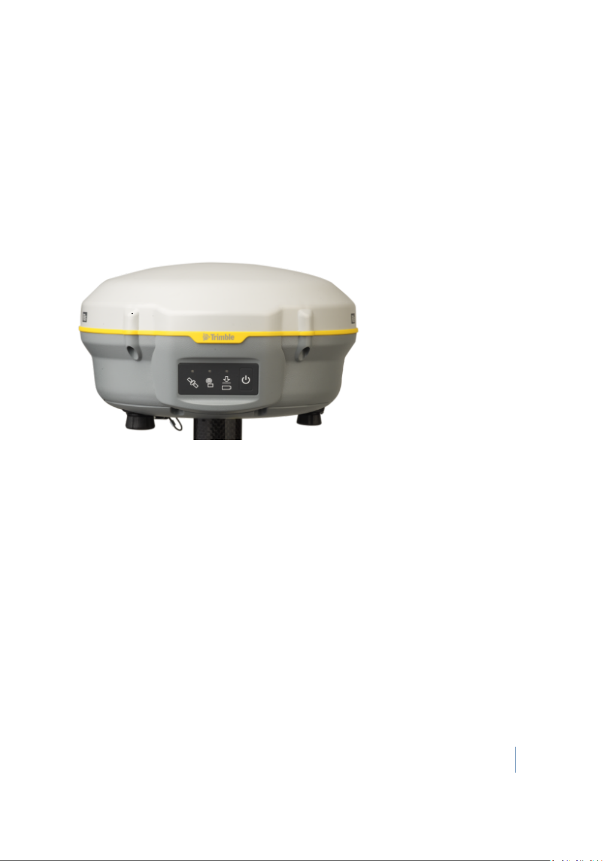
Parts of the R8s receiver
All operating controls on the receiver are located on the front panel. Serial ports and connectors are
located on the bottom of the unit.
Front panel
The following image shows the receiver front panel, which contains the three indicator light emitting
diodes (LEDs), and the Power button.
The Power button controls the receiver’s power on or off functions.
The indicator LEDs show the status of power, satellite tracking, and radio reception. For more
information, see LED behavior, page 23.
Lower housing
The following image shows the receiver lower housing, which contains the two serial ports, one TNC
radio antenna or GSM antenna connector (depending on the internal communication module
ordered), the removable battery compartment and the ⅝-11 threaded insert.
Trimble R8s GNSS Receiver User Guide 14
Page 15
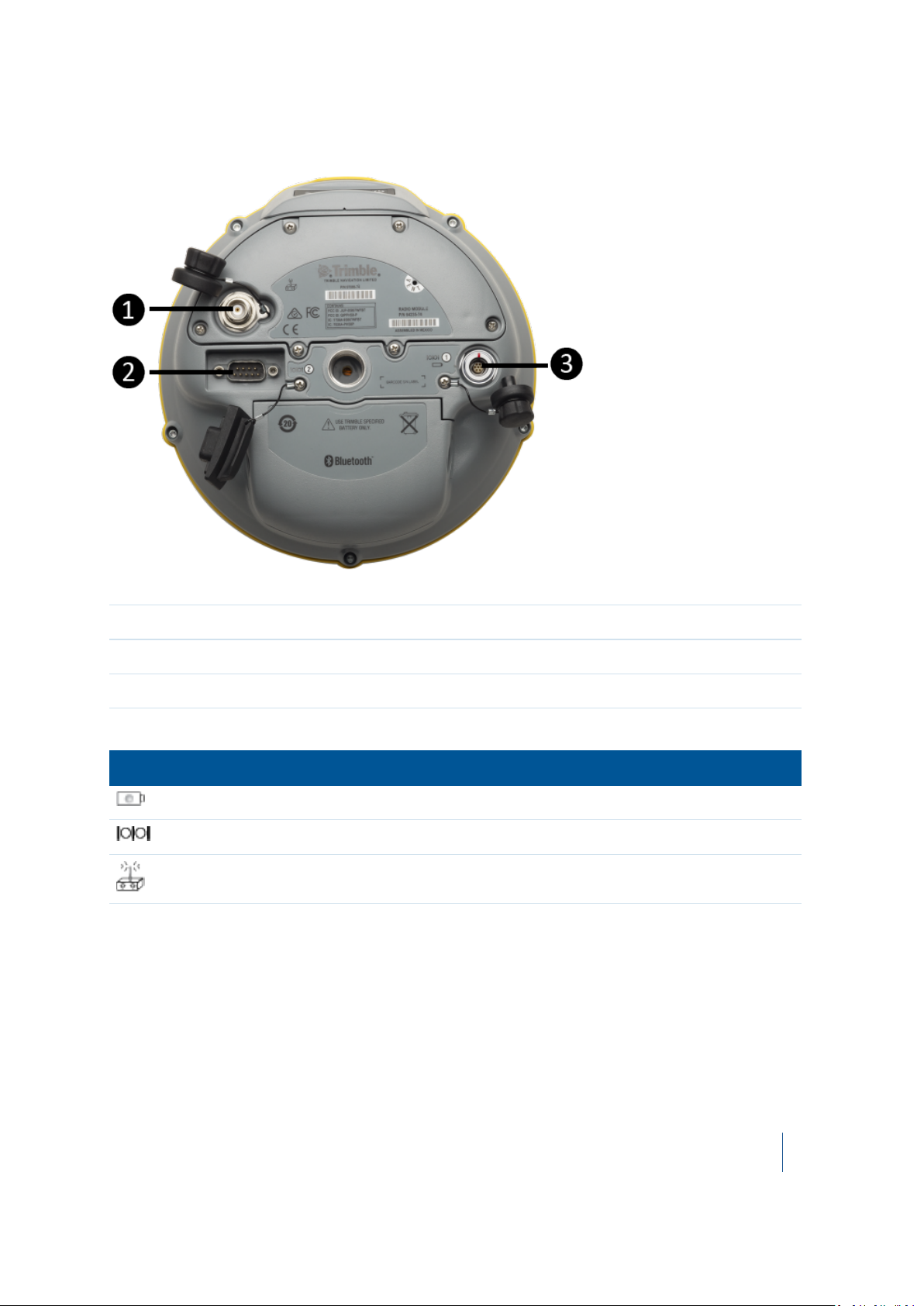
2 Setting up the Receiver
❶ Radio antenna connection
❷ Port 2
❸ Port 1
Each port or connector on the receiver is marked with an icon to indicate its main function:
Icon Name Connection
Port 1 Device, computer, external radio, power in
Port 2 Device, computer, external radio
Radio Radio communications antenna
Port 1 is a 7-pin 0-shell Lemo connector that supports RS-232 comms and external power input.
Port 1 has no power outputs.
Port 2 is a DB-9 male connector that allows for full 9-pin RS-232 comms. Port 2 does not support
power in or out. For more information, see Cables and Connectors, page 33 and Cables and
Connectors, page 33.
The TNC connector is for connecting a radio antenna to the receiver internal radio. A whip “rubber
duck” antenna is supplied with the system for units with internal UHF radios. This connector is not
used if you are using an external UHF radio or GSM.
Trimble R8s GNSS Receiver User Guide 15
Page 16

2 Setting up the Receiver
External UHF or GSM antenna
Depending on which module you have purchased, use this TNC connection for an external antenna
for the UHF or GSM antenna.
For more information on connecting the receiver, see the following sections in this chapter.
Setup guidelines
Consider the following guidelines when setting up the receiver.
CAUTION – To satisfy the RF Exposure requirements of the FCC, you must maintain a minimum separation
distance of 20 cm (approximately 8 in.) between yourself and the radiating UHF antenna for this device. For
mobile operation, the maximum gain of the UHF antenna must not exceed 0 dBi.
Operation near other radio equipment
When operating the receiver in member states of the European Union and in other counties which
adhere to the EU R&TTE requirements, while in the vicinity of aeronautical radionavigation
equipment operating between 2700 and 2900 MHz, or Fixed, Fixed Satellite (space to Earth) or
Mobile systems operating at 4170 MHz, a minimum separation of 5 meters must be maintained
between the receiver and such radio equipment.
Environmental conditions
Although the receiver has a waterproof housing, take reasonable care to protect the unit. Avoid
exposure to extreme environmental conditions, including:
l Water
l Heat greater than 65 °C (149 °F)
l Cold less than –40 °C (–40 °F)
l Corrosive fluids and gases
Sources of electrical interference
Avoid the following sources of electrical and magnetic noise:
l Gasoline engines (spark plugs)
l Televisions and PC monitors
l Alternators and generators
Trimble R8s GNSS Receiver User Guide 16
Page 17

2 Setting up the Receiver
l Electric motors
l Equipment with DC-to-AC converters
l Fluorescent lights
l Switching power supplies
General guidelines
WARNING – These receivers use a rechargeable Lithium-ion battery. To avoid personal injury or equipment
damage, ensure that you read and understand the Safety Information at the front of this manual.
The following guidelines apply whenever you set up the receiver for operation:
l When plugging in a Lemo cable, make sure that the red dots on the receiver port and the cable
connector line up. Do not use force to plug cables in, as this may damage the connector pins.
l When disconnecting a Lemo cable, grasp the cable by the sliding collar or lanyard and then pull
the cable connector straight out of the port. Do not twist the connector or pull on the cable
itself.
l To securely connect a TNC cable, align the cable connector with the receiver receptacle and
then thread the cable connector onto the receptacle until it is snug.
l To insert the internal battery, place the battery in the battery compartment, ensuring that the
contact points are in the correct position to align with the contacts in the receiver. Slide the
battery and compartment as a unit upward into the receiver until the battery compartment
latches are locked into position.
Setting up the receiver on a range pole
To mount the receiver on a range pole:
1. Thread the receiver onto the range pole.
2.
Attach the controller bracket to the pole.
3.
Insert the controller into the controller bracket:
Note – When using a Trimble TSC3, Trimble TSC2,® Trimble TCU, Trimble Tablet Rugged PC, or Trimble Slate
controller, no cabling is required, as shown below.
Trimble R8s GNSS Receiver User Guide 17
Page 18

2 Setting up the Receiver
Other system components
This section describes optional components that you can use with the receiver.
Radios
Radios are the most common data link for Real-Time Kinematic (RTK) surveying. The receiver is
available with an optional internal radio in the 450 MHz UHF band, or with an internal GSM module.
You can also connect an external radio to either receiver port, whether or not the internal radio is
installed.
Trimble R8s GNSS Receiver User Guide 18
Page 19

2 Setting up the Receiver
The receiver supports the following Trimble base radios with the internal 450 MHz radio:
l Trimble TDL 450H
l Trimble TDL 450L
l Trimble HPB450
l Trimble PDL450
l Receiver internal 450 MHz transmitter
l TRIMMARK™ 3 radio
l SiteNet™ 450 radio
Internal GSM setup
You can configure the optional internal GSM Module using the Trimble Access™ software. For more
information, refer to the field software documentation.
Internal radio setup
To configure the optional internal radio, use the Trimble Access software.
For more information, refer to the Trimble Access Help.
By default, the internal radio has only a few “test” frequencies installed at the factory. If you
purchased the transmit option, the broadcast frequencies must be programmed by the Trimble
distribution partner. You can program the receive frequencies using the Trimble Access software.
Refer to the Trimble Access Help.
Cellular modems and external radios
For a data communications link, you can use an internal or external radio, or an internal or external
cellular modem.
To connect an external cellular modem to the receiver, you need the following:
l A Trimble R8s GNSS receiver.
l A cellular modem, or a cellphone that can transmit and receive data.
l Serial (cellphone to DB9) cable (supplied with the cellular modem or phone).
l Port 2 of the receiver supports full RS-232 protocol, and should function properly with most
cellular phone cables. Some cellular units may require custom cabling.
Alternatively, the receiver also supports a cable-free Bluetooth connection with Bluetooth-
enabled cell phones.
For more information on using an external cellular modem as a data link, refer to the Trimble Access
or Trimble Survey Controller documentation.
Trimble R8s GNSS Receiver User Guide 19
Page 20

2 Setting up the Receiver
To connect an external radio modem to a receiver, you need the following:
l A receiver.
l An external radio capable of receiving and decoding Trimble data packets.
l Serial cable for either Port 1 or Port 2 of the receiver, as supplied by the radio manufacturer.
l Radio mount for the range pole.
Trimble R8s GNSS Receiver User Guide 20
Page 21

CHAPTER
General Operation
n Front panel controls
n Button functions
n LED behavior
n Logging data
All the controls that you need for general receiver operation are on the front panel.
For more information about other receiver panels, see Parts of the R8s receiver, page 14.
3
Trimble R8s GNSS Receiver User Guide 21
Page 22
3 General Operation
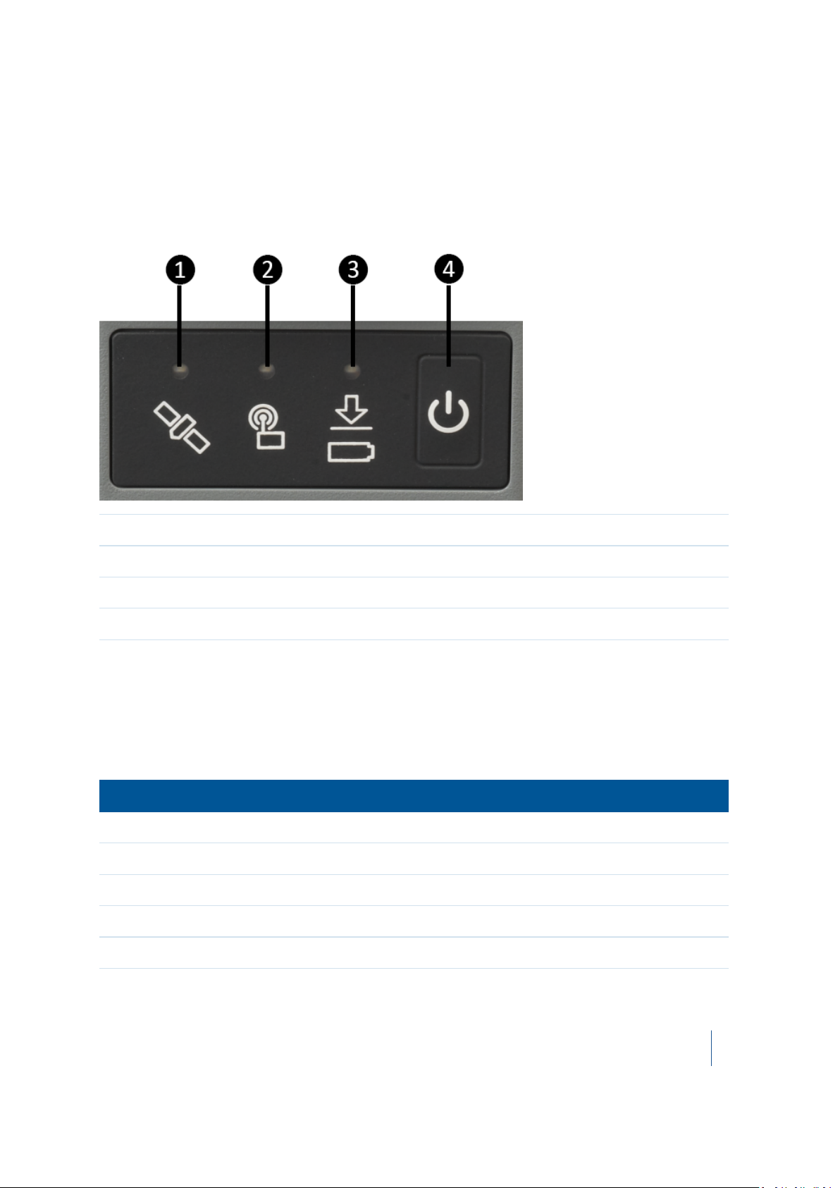
Front panel controls
The following image shows the receiver front panel controls for the power on/off functions, or
receiver reset. The LEDs provide power, radio, data logging, and SV tracking status information.
❶ Satellite tracking LED
❷ Radio LED
❸ Power / Data status LED
❹ Power button
Button functions
The receiver has only one button, the Power button. Press the Power button to turn on or turn
off the receiver, and to perform other functions, as described below.
To... Power button
turn on the receiver Press
turn off the receiver Hold for 2 seconds
delete the ephemeris file Hold for 15 seconds
reset the receiver to factory defaults Hold for 15 seconds
delete application files Hold for 30 seconds
Trimble R8s GNSS Receiver User Guide 22
Page 23

3 General Operation
Note – The term “press” means to press the button and release it immediately. The term “hold” means to
press the button and hold it down for the given time.
LED behavior
The three LEDs on the front panel of the receiver indicate various operating conditions. Generally, a
lit or slowly flashing LED indicates normal operation, a LED that is flashing quickly indicates a
condition that may require attention, and an unlit LED indicates that no operation is occurring.
The LED flash rates are:
l SLOW FLASH = LED is on and off equally for 0.5 seconds.
l FAST FLASH = LED is on and off equally for 0.1 seconds.
Receiver mode Power LED
Green
Receiver OFF OFF OFF OFF
Receiver ON:
Healthy power
Low power
Tracking <4 SVs
Tracking >4 SVs
Logging data internally
Transmitting internally
Receiving valid data
packets
No data packets ON OFF N/A
ON N/A N/A
Fast flash
ON
ON
Flashes off every 3
seconds
N/A
ON
Radio LED
Green
N/A N/A
N/A Fast flash
N/A Slow flash
N/A N/A
Flashes off when
transmitting
Slow flash N/A
Satellite
LED
Amber
N/A
Receiver in monitor ON Slow flash ON
Note – If a column shows “N/A”, that specific LED may or may not be on, but it is not relevant to that
particular mode.
Trimble R8s GNSS Receiver User Guide 23
Page 24

3 General Operation
Charging the receiver's battery
WARNING – Charge and use the rechargeable Lithium-ion battery only in strict accordance with the
instructions. Charging or using the battery in unauthorized equipment can cause an explosion or fire, and can
result in personal injury and/or equipment damage.
To prevent injury or damage:
– Do not charge or use the battery if it appears to be damaged or leaking.
–Charge the Lithium-ion batteries only in a Trimble battery charger, such as the dual battery charger P/N 6111600 (black) or P/N 53018010 (grey), or the five-battery system charger P/N 49499-00 (yellow/grey) or another
charger specified for this battery. Be sure to follow all instructions that are provided with the battery charger.
– Discontinue charging a battery that gives off extreme heat or a burning odor.
– Use the battery only in Trimble equipment that is specified to use it.
– Use the battery only for its intended use and according to the instructions in the product documentation.
WARNING – Do not damage the rechargeable Lithium-ion battery. A damaged battery can cause an
explosion or fire, and can result in personal injury and/or property damage.
To prevent injury or damage:
– Do not use or charge the battery if it appears to be damaged. Signs of damage include, but are not limited to,
discoloration, warping, and leaking battery fluid.
– Do not expose the battery to fire, high temperature, or direct sunlight.
– Do not immerse the battery in water.
– Do not use or store the battery inside a vehicle during hot weather.
– Do not drop or puncture the battery.
– Do not open the battery or short-circuit its contacts.
WARNING – Avoid contact with the rechargeable Lithium-ion battery if it appears to be leaking. Battery fluid
is corrosive, and contact with it can result in personal injury and/or property damage.
To prevent injury or damage:
– If the battery leaks, avoid contact with the battery fluid.
– If battery fluid gets into your eyes, immediately rinse your eyes with clean water and seek medical attention.
Do not rub your eyes!
– If battery fluid gets onto your skin or clothing, immediately use clean water to wash off the battery fluid.
The receiver can be powered by its internal battery or by an external power source connected to
Port 1.
If an external power source is connected to Port 1, it is used in preference to the internal battery.
When there is no external power source connected, or if the external power supply fails, the internal
battery is used.
The receiver is supplied with two rechargeable Lithium-ion batteries, and a dual battery charger.
Charge the Lithium-ion batteries only in a Trimble battery charger, such as the dual battery charger
P/N 61116-00 (black) or P/N 53018010 (grey), or the five-battery system charger P/N 49499-00
(yellow/grey) or another charger specified for this battery. The two batteries charge sequentially and
take approximately four hours each to fully charge.
Trimble R8s GNSS Receiver User Guide 24
Page 25

3 General Operation
To protect the battery from deep discharge (5 V or less), the receiver is designed to switch batteries
or cease drawing power when the battery pack discharges to 5.9 V.
A battery that has reached the deep discharge level cannot be recharged and must be replaced. The
following recommendations provide optimal performance and extend the life of your batteries:
l Fully charge all new batteries before use.
l Do not allow the batteries to discharge below 5 V.
l Keep all batteries on continuous charge when not in use. Batteries may be kept on charge
indefinitely without damage to the receiver or batteries.
l Do not store batteries in the receiver or external charger unless power is applied.
l If you must store the batteries, fully charge them before storing and then recharge them at
least every three months.
Charging the battery
The rechargeable Lithium-ion battery is supplied partially charged. Charge the battery completely
before using it for the first time. If the battery has been stored for longer than six months, charge it
before use.
To protect the battery from deep discharge (5 V or less), the receiver is designed to switch batteries
or cease drawing power when the battery pack discharges to 5.9 V.
A battery that has reached the deep discharge level cannot be recharged and must be replaced. The
following recommendations provide optimal performance and extend the life of your batteries:
l Fully charge all new batteries prior to use.
l Do not allow the batteries to discharge below 5 V.
l Keep all batteries on continuous charge when not in use. Batteries may be kept on charge
indefinitely without damage to the receiver or batteries.
l Do not store batteries in the receiver or external charger unless power is applied.
l If you must store the batteries, fully charge them before storing and then recharge them at
least every three months.
Storing the Lithium-ion battery
All battery types discharge over time when they are not being used. Batteries also discharge faster in
colder temperatures. If a Lithium-ion battery is to be stored for long periods of time, make sure it is
fully charged before storing and re-charged at least every three months.
Disposing of the rechargeable Lithium-ion battery
Discharge the Lithium-ion battery before disposing of it. When disposing of the battery, ensure that
you do so in an environmentally sensitive manner. Adhere to any local and national regulations
concerning battery disposal or recycling.
Trimble R8s GNSS Receiver User Guide 25
Page 26

3 General Operation
Power output
The receiver does not supply power from either of its two ports.
Firmware
A receiver’s firmware is the program inside the receiver that controls receiver operations and
hardware. You can upgrade the firmware for the receiver using the Trimble Installation Manager
software that you can download from www.trimble.com.
For more information, refer to the Trimble Installation Manger Help.
CAUTION – Downgrading the firmware deletes all application files on the receiver.
Logging data
You can log data internally or to a Trimble controller.
Logging internally
The receiver logs raw data on internal memory.
You can then use the Trimble Data Transfer utility or Trimble Business Center software to transfer
logged data files to the office computer.
Note – If you use the Data Transfer utility to download the internally-logged files, a DAT (*.dat) file is
automatically created after the download. DAT files do not contain GLONASS data. If you have Trimble
Business Center software, the T0x (T01 or T02) file that is stored on the receiver can be directly downloaded.
The T0x files contain any collected GLONASS data. Trimble Business Center software can process GLONASS
data, if you purchased that option.
CAUTION – The receiver allows for a maximum of 200 files on the internal memory. The filenames must be
in 8.3 format, otherwise, files copied to the internal memory may cause data corruption or loss of data
when logging.
Data is logged using the current logging settings configured in the receiver. Data files logged internally are
named automatically.
The receiver allows for a maximum of 200 files on the internal memory. The filenames must be in 8.3
format, otherwise, files copied to the internal memory may cause data corruption or loss of data
when logging.
Data is logged using the current logging settings configured in the receiver. Data files logged
internally are named automatically.
Trimble R8s GNSS Receiver User Guide 26
Page 27

3 General Operation
To begin internal logging, you must use a Trimble controller running the Trimble Access software.
The receiver does not have a continuously running internal clock when it is turned off, so you can
conduct timed survey sessions only if the receiver is turned on and connected to a power source.
When the internal memory is full, the receiver stops logging data, and the Power LED stops flashing
and remains on continuously. Existing data files are not overwritten. You can use the Auto-delete
option to override this action and automatically delete the oldest files when the receiver memory is
full. However, you should use this option with caution because it can result in loss of data.
Approximate storage requirements for different logging rates are shown below. The values shown
are for a one-hour logging session with six satellites visible.
Logging rate Memory required
10 Hz 2,588 KB
1 Hz
5 seconds 87 KB
15 seconds 37 KB
335 KB
Logging to a Trimble controller
When the receiver is connected to a Trimble controller running the Trimble Access software, you can
log GNSS data from the receiver to the controller, or to a data card inserted in the controller. When
you use a Trimble controller, you do not use the receiver’s controls. Instead, you use the controller
functions to set logging options, specify filenames, and control when logging occurs.
Controller software job files and the corresponding raw data files can be transferred to an office
computer using the Trimble Data Transfer utility.
For more information on logging data from a receiver using a Trimble controller, refer to the user
guide for your particular controller.
Trimble R8s GNSS Receiver User Guide 27
Page 28

CHAPTER
4
Configuring the receiver
n Configuring the receiver in real time
n Configuring the receiver using application files
The receiver has no controls to change settings. To configure the receiver, do one of the following:
l Configure the receiver in real time using the Trimble Access software.
l Apply the settings in an application file.
This chapter provides a brief overview of each of these methods and describes the contents and use of
application files.
Trimble R8s GNSS Receiver User Guide 28
Page 29

4 Configuring the receiver
Configuring the receiver in real time
The Trimble Access software supports real-time configuration of the receiver.
When you configure the receiver in real time, use the software to specify which settings you want to
change. When you apply the changes, the receiver settings change immediately.
Any changes that you apply to the receiver are reflected in the current application file, which is
always present in the receiver. The current application file always records the most recent
configuration, so if you apply further changes (either in real time or using an application file) the
current file is updated and there is no record of the changes that you applied originally.
Configuring the receiver using application files
The receiver Web Interface can be used to create and apply application files. Refer to the receiver
Web Interface help for more information.
Trimble R8s GNSS Receiver User Guide 29
Page 30

CHAPTER
5
Default Settings
n Default receiver settings
n Resetting the receiver to factory defaults
All receiver settings are stored in application files. The default application file is stored permanently in the
receiver, and contains the factory default settings for the receiver. Whenever the receiver is reset to its
factory defaults, the current settings (stored in the current application file, current.cfg) are reset to the
values in the default application file.
For more information, see Configuring the receiver using application files, page 29.
Trimble R8s GNSS Receiver User Guide 30
Page 31

5 Default Settings
Default receiver settings
These settings are defined in the default application file.
Function Settings Factory default
SV Enable - All SVs enabled
General Controls Elevation mask 13°
PDOP mask 7
RTK positioning mode Low Latency
Motion Kinematic
Serial Port 1: Baud rate 38400
Format 8-None-1
Flow control None
Serial Port 2: Baud rate 38400
Format 8-None-1
Flow control None
Input Setup Station Any
NMEA/ASCII (all
supported messages)
Streamed Output All types Off
RT17/Binary
Reference Position Latitude 0°
Antenna Type Trimble R8s Model 1 internal
All ports Off
Offset=00
Longitude 0°
Altitude 0.00 m HAE
All ports Off
Height (true vertical) 0.00 m
Group All
Measurement method Bottom of mount
Trimble R8s GNSS Receiver User Guide 31
Page 32

5 Default Settings
Resetting the receiver to factory defaults
To reset the receiver to its factory defaults, press and hold down the receiver’s Power button for 15
seconds.
Default behavior
The factory defaults specified above are applied whenever you start the receiver. If a power up file is
present in the receiver, its settings are applied immediately after the default settings, so you can use
a power up file to define your own set of defaults.
When you turn the receiver on
and …
it is the first time that the
receiver has been used
you have reset the receiver to
its factory defaults
you have performed a full reset the factory defaults, because resetting
then logging settings are … and logging …
the factory defaults does not begin
automatically
the factory defaults, or those in the power
up file
deletes any power up file
does not begin
automatically
does not begin
automatically
Power up settings
When you turn off the receiver, any changes that you have made to logging settings are lost and
these settings are returned to the factory defaults. Other settings remain as defined in the current
file. The next time you turn on the receiver, the receiver checks for a power up file and, if one is
present, applies the settings in this file.
When you use the Power button to turn off and then
turn on the receiver and …
you changed the receiver settings by applying an
application file
then logging
settings are …
the factory
defaults
and all other
settings are …
the last settings
used
you changed the receiver settings using configuration
software
the factory
defaults
Trimble R8s GNSS Receiver User Guide 32
the last settings
used
Page 33

CHAPTER
6
Cables and Connectors
n Port 1 and 2 connectors
n Power/serial data cables
This chapter describes the pinouts for the receiver standard and optional cables. This information can be
used to prepare special cables for connecting the receiver to devices and instruments not supported by
the standard and optional cables.
Trimble R8s GNSS Receiver User Guide 33
Page 34

6 Cables and Connectors
Port 1 and 2 connectors
The following figures show the receiver serial ports and pinout connections.
Port 1:
Trimble R8s GNSS Receiver User Guide 34
Page 35

6 Cables and Connectors
Port 2:
Pin Pinout function
Port 1 – 7-pin Lemo
Port 2 – DB-9
1 Signal ground DCD
2 Power ground RXD
3 TXD TXD
4 N/C DTR
5 N/C Signal ground
6 + Power in DSR
7 TRXD RTS
8 N/A CTS
9 N/A Ring indicator
Trimble R8s GNSS Receiver User Guide 35
Page 36

6 Cables and Connectors
Power/serial data cables
The data-I/O cable is supplied with the receiver.
The table below assumes that the cable is attached to the connector labeled Port 2:
DB-9 Female 9-pin
DB-9 Female 9-pin
Pin Function Pin Function
1-6 DCD5_232 4 DTR5_232
2 RX5_232 3 TX5_232
3 TX5_232 2 RX5_232
4 DTR5_232 1-6 DCD5_232
5 GND 5 GND
7 RTS5_232 8 CTS5_232
8 CTS5_232 7 RTS5_232
9
no connection RI5_232 9
9
This data cable may be used for firmware upgrades and other computer functions with the receiver.
Power must be supplied to the receiver through Port 1, or from the internal battery.
Note – This pinout information also applies to the power/serial data cable, which is optional for use with the
receiver. This cable can be used for firmware upgrades through Port 1, while also supplying external power.
The table below assumes that the cable is attached to the connector labeled Port 1:
Lemo 0-shell connector 7-pin
Pin Function Pin Color Function Color Function
1 GND <--> 5
2 GND --> Black V-OUT
3 TX3_232 --> 2 Orange TXD
4 RTS/TXD --> 8 Blue RTS
5 CTS/RXD <-- 7 Green CTS
6 PWR_IN <-- Red Power IN (+)
7 RX3_232 <-- 3 Yellow TXD
Direction
DE9-F connector 7 Cond Power lead 2 Cond
Brown
Signal ground
Trimble R8s GNSS Receiver User Guide 36
Page 37

CHAPTER
7
NMEA Output Messages
n NMEA-0183 messages: Overview
n NMEA-0183 messages: Common message elements
n List of supported NMEA messages
This appendix describes the formats of the subset of NMEA-0183 messages that are available for output
by the receiver. For a copy of the NMEA-0183 Standard, go to the National Marine Electronics Association
website at www.nmea.org.
Trimble R8s GNSS Receiver User Guide 37
Page 38

7 NMEA Output Messages
NMEA-0183 messages: Overview
When NMEA-0183 output is enabled, a subset of NMEA-0183 messages can be output to external
instruments and equipment connected to the receiver serial ports. These NMEA-0183 messages let
external devices use selected data collected or computed by the GNSS receiver.
All messages conform to the NMEA-0183 version 3.01 format. All begin with $ and end with a
carriage return and a line feed. Data fields follow comma (,) delimiters and are variable in length. Null
fields still follow comma (,) delimiters, but contain no information.
An asterisk (*) delimiter and checksum value follow the last field of data contained in an NMEA-0183
message. The checksum is the 8-bit exclusive of all characters in the message, including the commas
between fields, but not including the $ and asterisk delimiters. The hexadecimal result is converted
to two ASCII characters (0–9, A–F). The most significant character appears first.
The following table summarizes the set of NMEA messages supported by the receiver.
Message Function
DP Dynamic positioning (proprietary Fugro message)
DTM Datum reference information
GBS GNSS satellite fault detection (RAIM support)
GGA Time, position, and fix related data
GGK Time, position, position type, DOP
GLL Position data: position fix, time of position fix, and status
GNS GNS Fix data
GRS GRS range residuals
GSA GPS DOP and active satellites
GST Position error statistics
GSV Number of SVs in view, PRN, elevation, azimuth, and SNR
HDT Heading from True North
LLQ Leica local position and quality
PJK Local coordinate position output
PJT Projection type
PTNL,AVR Time, yaw, tilt, range, mode, PDOP, and number of SVs for Moving Baseline RTK
Trimble R8s GNSS Receiver User Guide 38
Page 39

7 NMEA Output Messages
Message Function
PTNL,BPQ Base station position and position quality indicator
PTNL,DG L-band corrections and beacon signal strength and related information
PTNL,GGK Time, position, position type, and DOP values
PTNL,PJK Time, position, position type, and DOP values
PTNL,VGK Time, locator vector, type, and DOP values
PTNL,VHD Heading Information
RMC Position, Velocity, and Time
ROT Rate of turn
VTG Actual track made good and speed over ground
ZDA UTC day, month, and year, and local time zone offset
For a copy of the NMEA-0183 Standard, go to the National Marine Electronics Association website at
www.nmea.org.
Trimble R8s GNSS Receiver User Guide 39
Page 40

7 NMEA Output Messages
NMEA-0183 messages: Common message elements
Each message contains:
l
a message ID consisting of $GP followed by the message type. For example, the message ID of
the GGA message is $GPGGA.
l
a comma.
l
a number of fields, depending on the message type, separated by commas.
l
an asterisk.
l
a checksum value.
The following example shows a simple message with a message ID ($GPGGA), followed by 13 fields
and a checksum value:
$GPGGA,172814.0,3723.46587704,N,12202.26957864,W,2,6,1.2,18.893,M,-25.669,M,2.0,0031*4F
Message values
NMEA messages that the receiver generates contains the following values:
Value Description
Latitude and
Longitude
Direction Direction (north, south, east, or west) is represented by a single character: N ,
Time Time values are presented in Universal Time Coordinated (UTC) and are
Latitude is represented as ddmm.mmmm and longitude is represented as
dddmm.mmmm, where:
l
dd or ddd is degrees
l
mm.mmmm is minutes and decimal fractions of minutes
S , E , or W.
represented as hhmmss.ss, where:
l
hh is hours, from 00 through 23
l
mm is minutes
l
ss.ss is seconds with variable length decimal-fraction of seconds
Trimble R8s GNSS Receiver User Guide 40
Page 41

7 NMEA Output Messages
List of supported NMEA messages
NMEA-0183 message: DP (Dynamic Positioning)
Proprietary Fugro message
The resulting message is shorter than the maximum defined message length of 82 characters, even
with mm level resolution in Latitude/Longitude.
$PFUGDP,GG,hhmmss.ss, ddmm.mmmmm,N, dddmm.mmmmm,E, NN,Q,DD,aa.a,bb.b,ddd,rr.r
An example of the DP message string is:
$PFUGDP,GN,033615.00,3953.88002,N,10506.75324,W,13,9,FF,0.1,0.1,149,0.1*13
DP message fields
Field Meaning
0 Message ID $PFUGDP
1 Two-character code for GPS (GP), GLONASS (GL) or GNSS (GN) data
2 UTC time (hhmmss.ss)
3-4 Latitude, in degrees and decimal minutes (ddmm.mmmmm) and Latitude sign (N/S)
5-6 Longitude, in degrees and decimal minutes (dddmm.mmmmm) and Longitude sign
(E/W)
7 Total number of satellites (GPS + GLONASS)
8 DPVOA (UK00A) quality indicator
9 DGNSS mode indicator (as NMEA standard for $ GNS)
10 Error ellipse standard deviation semi-major axis, in meters (aa.a)
11 Error ellipse standard deviation semi-minor axis, in meters (bb.b)
12 Direction of the error ellipse, in degrees
13 RMS value of the standard deviation of the range inputs to the navigation process
1
This quality indicator is defined in Guidelines on the use of DGPS in as a positioning reference in
DP Control Systems IMCA M141, dated Oct 1997 www.imcaint.com/publications/marine/imca.html.
1
1
Trimble R8s GNSS Receiver User Guide 41
Page 42

7 NMEA Output Messages
NMEA-0183 message: DTM
The DTM message identifies the local geodetic datum and datum offsets from a reference datum.
This sentence is used to define the datum to which a position location, and geographic locations in
subsequent sentences, is referenced.
An example of the DTM message string is:
$GPDTM,W84,,0.0,N,0.0,W,0.0,W84*7D
DTM message fields
Field Meaning
0 Message ID $GPDTM
1 Local datum code (CCC):
W84 – WGS-84
W72 – WGS-72
S85 – SGS85
P90 – PE90
999 – User-defined
IHO datum code
2 Local datum subdivision code (x)
3 Latitude offset, in minutes (x.x)
4 N/S (x)
5 Longitude offset, in minutes (x.x)
6 E/W (x)
7 Altitude offset, in meters (x.x)
8 Reference datum code (CCC):
W84 – WGS-84
W72 – WGS-72
S85 – SGS85
P90 – PE90
NMEA-0183 message: GBS
GNSS satellite fault detection (RAIM support)
An example of the GBS message string is:
Trimble R8s GNSS Receiver User Guide 42
Page 43

7 NMEA Output Messages
$GPGBS,015509.00,-0.031,-0.186,0.219,19,0.000,-0.354,6.972*4D
GBS message fields
Field Meaning
0 Message ID $--GBS.
Talker ID can be:
GA: Galileo
GB: Beidou
GP: GPS. To provide information specific to the GPS constellation when more than one
constellation is used for the differential position fix.
GL: GLONASS. To provide information specific to the GLONASS constellation when more
than one constellation is used for the differential position fix.
GN: Combined GNSS position. GNSS position fix from more than one constellation, for
example, GPS and GLONASS.
GQ: QZSS
1 UTC of position fix
2 Expected error in latitude, in meters, due to bias, with noise = 0
3 Expected error in longitude, in meters, due to bias, with noise = 0
4 Expected error in altitude, in meters, due to bias, with noise = 0
5 ID number of most likely failed satellite
6 Probability of missed detection of most likely failed satellite
7 Estimate of bias, in meters, on the most likely failed satellite
8 Standard deviation of bias estimate
9 The checksum data, always begins with *
If NMEA-0183 version 4.10 is selected, the 9th, 10th, and 11th fields become:
Trimble R8s GNSS Receiver User Guide 43
Page 44

7 NMEA Output Messages
Field Meaning
9
10
11 The checksum data, always begins with *
System ID based on:
GPS 1
GLONASS
Galileo
Beidou
QZSS
Signal ID based on:
GPS 1
GLONASS
Galileo
Beidou
QZSS
2
3
4
0
1
7
Null
Null
NMEA-0183 message: GGA
Time, position, and fix related data
An example of the GBS message string is:
$GPGGA,172814.0,3723.46587704,N,12202.26957864,W,2,6,1.2,18.893,M,-25.669,M,2.0 0031*4F
Note – The data string exceeds the NMEA standard length.
GGA message fields
Field Meaning
0 Message ID $GPGGA
1 UTC of position fix
2 Latitude
3 Direction of latitude:
N: North
Trimble R8s GNSS Receiver User Guide 44
Page 45

7 NMEA Output Messages
Field Meaning
S: South
4 Longitude
5 Direction of longitude:
E: East
W: West
6 GPS Quality indicator:
0: Fix not valid
1: GPS fix
2: Differential GPS fix (DGNSS), SBAS, OmniSTAR VBS, Beacon, RTX in GVBS mode
3: Not applicable
4: RTK Fixed, xFill
5: RTK Float, OmniSTAR XP/HP, Location RTK, RTX
6: INS Dead reckoning
7 Number of SVs in use, range from 00 through to 24+
8 HDOP
9 Orthometric height (MSL reference)
10 M: unit of measure for orthometric height is meters
11 Geoid separation
12 M: geoid separation measured in meters
13 Age of differential GPS data record, Type 1 or Type 9. Null field when DGPS is not used.
14 Reference station ID, range 0000-4095. A null field when any reference station ID is
selected and no corrections are received1.
15 The checksum data, always begins with *
Note – If a user-defined geoid model, or an inclined plane is loaded into the receiver, then the height output in
the NMEA GGA string is always the orthometric height (height above a geoid). The orthometric height is
output even if no user-defined geoid is loaded (there is a simplified default geoid in the receiver), or if a userdefined geoid is loaded, or if an inclined plane is used.
1
When using OmniSTAR services, the Reference Station ID indicates the following services:
VBS 100=VBS; 1000=HP; 1001 = HP/XP (Orbits) ; 1002 = HP/G2 (Orbits); 1008 = XP (GPS); 1012 = G2
(GPS); 1013 = G2 (GPS/GLONASS); 1014 = G2 (GLONASS); 1016 = HP/XP (GPS); 1020 = HP/G2 (GPS) ;
1021 = HP/G2 (GPS/GLONASS).
Trimble R8s GNSS Receiver User Guide 45
Page 46

7 NMEA Output Messages
NMEA-0183 message: GLL
Position data: position fix, time of position fix, and status
An example of the GLL message string is:
$GPGLL,3953.88008971,N,10506.75318910,W,034138.00,A,D*7A
GLL message fields
Field Meaning
0 Message ID $GPGLL
1 Latitude in dd mm,mmmm format (0-7 decimal places)
2 Direction of latitude N: North S: South
3 Longitude in ddd mm,mmmm format (0-7 decimal places)
4 Direction of longitude E: East W: West
5 UTC of position in hhmmss.ss format
6 Status indicator:
A: Data valid
V: Data not valid
This value is set to V (Data not valid) for all Mode Indicator values except A
(Autonomous) and D (Differential)
7 The checksum data, always begins with *
Mode indicator:
A: Autonomous mode
D: Differential mode
E: Estimated (dead reckoning) mode
M: Manual input mode
S: Simulator mode
N: Data not valid
NMEA-0183 message: GNS
GNSS fix data
GNSS capable receivers will always output this message with the GN talker ID
Trimble R8s GNSS Receiver User Guide 46
Page 47

7 NMEA Output Messages
GNSS capable receivers will also output this message with the GP and/or GL talker ID when using
more than one constellation for the position fix
An example of the GNS message output from a GNSS capable receiver is:
$GNGNS,014035.00,4332.69262,S,17235.48549,E,RR,13,0.9,25.63,11.24,,*70<CR><LF>
$GPGNS,014035.00,,,,,,8,,,,1.0,23*76<CR><LF>
$GLGNS,014035.00,,,,,,5,,,,1.0,23*67<CR><LF>
GNS message fields
Field Meaning
0 Message ID $--GNS
Talker ID can be:
GA: Galileo
GB: Beidou
GP: GPS. When more than one constellation is used.
GL: GLONASS. When more than one constellation is used.
GN: Combined GNSS position, for example, GPS and GLONASS.
GQ: QZSS
1 UTC of position fix
2 Latitude
3 Direction of latitude:
N: North
S: South
4 Longitude
5 Direction of longitude:
E: East
W: West
6 Mode indicator:
l
Variable character field with one character for each supported constellation.
l
First character is for GPS.
l
Second character is for GLONASS.
l Third character is Galileo.
l
Subsequent characters will be added for new constellation.
Each character will be one of the following:
N = No fix. Satellite system not used in position fix, or fix not valid
Trimble R8s GNSS Receiver User Guide 47
Page 48

7 NMEA Output Messages
Field Meaning
A = Autonomous. Satellite system used in non-differential mode in position fix
D = Differential (including all OmniSTAR services). Satellite system used in differential
mode in position fix
P = Precise. Satellite system used in precision mode. Precision mode is defined as: no
deliberate degradation (such as Selective Availability) and higher resolution code (Pcode) is used to compute position fix
R = Real Time Kinematic. Satellite system used in RTK mode with fixed integers
F = Float RTK. Satellite system used in real-time kinematic mode with floating integers
E = Estimated (dead reckoning) Mode
M = Manual Input Mode
S = Simulator Mode
7 Number of SVs in use, range 00–99
8 HDOP calculated using all the satellites (GPS, GLONASS, and any future satellites) used in
computing the solution reported in each GNS sentence.
9 Orthometric height in meters (MSL reference)
10 Geoidal separation in meters – The difference between the earth ellipsoid surface and
mean-sea-level (geoid) surface defined by the reference datum used in the position
solution.
“-” = mean-sea-level surface below ellipsoid.
11 Age of differential data – Null if talker ID is GN, additional GNS messages follow with GP
and/or GL Age of differential data.
12 Reference station ID1, range 0000-4095
– Null if Talker ID is GN. Additional GNS messages follow with GP and/or GL Reference
station ID.
13 The checksum data, always begins with *
Note – If a user-defined geoid model, or an inclined plane is loaded into the receiver, then the height output in
the NMEA GNS string is always the orthometric height (height above a geoid). The orthometric height is
output even if no user-defined geoid is loaded (there is a simplified default geoid in the receiver), or if a userdefined geoid is loaded, or if an inclined plane is used.
1
When using OmniSTAR services, the Reference Station ID indicates the following services:
VBS 100=VBS; 1000=HP; 1001 = HP/XP (Orbits) ; 1002 = HP/G2 (Orbits); 1008 = XP (GPS); 1012 = G2
(GPS); 1013 = G2 (GPS/GLONASS); 1014 = G2 (GLONASS); 1016 = HP/XP (GPS); 1020 = HP/G2 (GPS) ;
1021 = HP/G2 (GPS/GLONASS).
Trimble R8s GNSS Receiver User Guide 48
Page 49

7 NMEA Output Messages
NMEA-0183 message: GRS
GRS range residuals
The GRS message is used to support the Receiver Autonomous Integrity Monitoring (RAIM).
Note – Because the contents of this NMEA message do not change significantly during a one-second interval,
the receiver outputs this message at a maximum rate of 1 Hz.
An example of the GRS message string is:
$GPGRS,220320.0,0,-0.8,-0.2,-0.1, -0.2,0.8,0.6,,,,,,1,*55
GRS message fields
Field Meaning
0 Message ID $GPGRS
Talker ID can be:
GA: Galileo
GB: Beidou
GP: GPS. To provide information specific to the GPS constellation when more than one
constellation is used for the differential position fix.
GL: GLONASS. To provide information specific to the GLONASS constellation when more
than one constellation is used for the differential position fix.
GN: Combined GNSS position. GNSS position fix from more than one constellation, for
example, GPS and GLONASS.
GQ: QZSS
1 UTC of GGA position fix
2 Residuals
0: Residuals used to calculate position given in the matching GGA line
1: Residuals recomputed after the GGA position was computed
3–14 Range residuals for satellites used in the navigation solution, in meters
15 Satellite System ID: GP(1), GL(2), GA(3), GB(4), GQ(0)
NMEA-0183 message: GSA
GPS DOP and active satellites
An example of the GSA message string is:
$GNGSA,A,3,21,5,29,25,12,10,26,2,,,,,1.2,0.7,1.0*27
Trimble R8s GNSS Receiver User Guide 49
Page 50

7 NMEA Output Messages
$GNGSA,A,3,65,67,80,81,82,88,66,,,,,,1.2,0.7,1.0*20
GSA message fields
Field Meaning
0 Message ID $GNGSA
1 Mode 1, M = manual, A = automatic
2 Mode 2, Fix type, 1 = not available, 2 = 2D, 3 = 3D
3 PRN number, 01 through 32 for GPS, 33 through 64 for SBAS, 64+ for GLONASS
4 PDOP: 0.5 through 99.9
5 HDOP: 0.5 through 99.9
6 VDOP: 0.5 through 99.9
7 The checksum data, always begins with *
If NMEA-0183 version 4.10 is selected, the 7th and 8th fields become:
Field Meaning
7
8 The checksum data, always begins with *
System ID based on:
GPS 1
GLONASS
Galileo
Beidou
QZSS
2
3
4
0
NMEA-0183 message: GST
Position error statistics
An example of the GST message string is:
$GPGST,172814.0,0.006,0.023,0.020,273.6,0.023,0.020,0.031*6A
The Talker ID ($--) will vary depending on the satellite system used for the position solution:
Trimble R8s GNSS Receiver User Guide 50
Page 51

7 NMEA Output Messages
l
$GP - GPS only
l
$GL - GLONASS only
l
$GN - Combined
GST message fields
Field Meaning
0 Message ID $GPGST
1 UTC of position fix
2 RMS value of the pseudorange residuals; includes carrier phase residuals during
periods of RTK (float) and RTK (fixed) processing
3 Error ellipse semi-major axis 1 sigma error, in meters
4 Error ellipse semi-minor axis 1 sigma error, in meters
5 Error ellipse orientation, degrees from true north
6 Latitude 1 sigma error, in meters
7 Longitude 1 sigma error, in meters
8 Height 1 sigma error, in meters
9 The checksum data, always begins with *
NMEA-0183 message: GSV
Satellite information
The GSV message string identifies the number of SVs in view, the PRN numbers, elevations,
azimuths, and SNR values. Example GSV message strings are:
$GPGSV,8,1,25,21,44,141,47,15,14,049,44,6,31,255,46,3,25,280,44*75
$GPGSV,8,2,25,18,61,057,48,22,68,320,52,27,34,268,47,24,32,076,45*76
$GPGSV,8,3,25,14,51,214,49,19,23,308,46*7E
$GPGSV,8,4,25,51,44,183,49,46,41,169,43,48,36,220,45*47
$GLGSV,8,5,25,82,49,219,52,76,22,051,41,83,37,316,51,67,57,010,51*6C
$GLGSV,8,6,25,77,24,108,44,81,10,181,46,78,1,152,34,66,18,060,45*50
$GLGSV,8,7,25,68,37,284,50*5C
$GBGSV,8,8,25,111,35,221,47,112,4,179,39,114,48,290,48*11
Trimble R8s GNSS Receiver User Guide 51
Page 52

7 NMEA Output Messages
GSV message fields
Field Meaning
0 Message ID
1 Total number of messages of this type in this cycle
2 Message number
3 Total number of SVs visible
4 SV PRN number
5 Elevation, in degrees, 90° maximum
6 Azimuth, degrees from True North, 000° through 359°
7 SNR, 00 through 99 dB (null when not tracking)
8–11 Information about second SV, same format as fields 4 through 7
12–15 Information about third SV, same format as fields 4 through 7
16–19 Information about fourth SV, same format as fields 4 through 7
20 The checksum data, always begins with *
Note –
$GPGSV indicates GPS and SBAS satellites. If the PRN is greater than 32, this indicates an SBAS PRN,
87 should be added to the GSV PRN number to determine the SBAS PRN number.
$GLGSV indicates GLONASS satellites. 64 should be subtracted from the GSV PRN number to
determine the GLONASS PRN number.
$GBGSV indicates BeiDou satellites. 100 should be subtracted from the GSV PRN number to
determine the BeiDou PRN number.
$GAGSVindicates Galileo satellites.
$GQGSVindicates QZSS satellites.
NMEA-0183 message: HDT
Heading from True North
Note – The heading computation in this message is computed from the moving baseline vector, which
requires a two-antenna system.
An example of the HDT string is:
$GPHDT,123.456,T*00
Trimble R8s GNSS Receiver User Guide 52
Page 53

7 NMEA Output Messages
Heading from true north message fields
Field Meaning
0 Message ID $GPHDT
1 Heading in degrees
2 T: Indicates heading relative to True North
3 The checksum data, always begins with *
NMEA-0183 message: LLQ
Leica local position and quality
An example of the LLQ message string is:
$GPLLQ,034137.00,210712,,M,,M,3,15,0.011,,M*15
Field Meaning
0 Message ID $GPLLQ
1 hhmmss.ss – UTC time of position
2 ddmmyy – UTC date
3 xxx.xxx – Grid easting (meters)
4 M – Meter, fixed text
5 xxxx.xxxx – Grid northing (meters)
6 M – Meter, fixed text
7 x – GPS quality. 0 = not valid. 1 = GPS Nav Fix. 2 = DGPS Fix. 3 = RTK Fix.
8 x – Number of satellites used in computation
9 xx.xx – Position quality (meters)
10 xxxx.xxxx – Height (meters)
11 M – Meter, fixed text
*hh – checksum
<CR> – carriage return
<LF> – Line feed
Trimble R8s GNSS Receiver User Guide 53
Page 54

7 NMEA Output Messages
NMEA-0183 message: PTNL,AVR
Time, yaw, tilt/roll, range for moving baseline RTK
Note – The heading computation in this message is computed from the moving baseline vector, which
requires a two-antenna system.
An example of the PTNL,AVR message string is:
$PTNL,AVR,212405.20,+52.1531,Yaw,-0.0806,Tilt,,,12.575,3,1.4,16*39
$PTNL,AVR,212604.30,+52.1800,Yaw,,,-0.0807,Roll,12.579,3,1.4,16*21
AVR message fields
Field Meaning
0 Message ID $PTNL,AVR
1 UTC of vector fix
2 Yaw angle, in degrees
3 Yaw
4 Tilt angle, in degrees
5 Tilt
6 Reserved
7
8
9 GPS quality indicator:
10 PDOP
11 Number of satellites used in solution
Reserved
Range, in meters
0: Fix not available or invalid
1: Autonomous GPS fix
2: Differential carrier phase solution RTK (Float)
3: Differential carrier phase solution RTK (Fix)
4: Differential code-based solution, DGPS
12 The checksum data, always begins with *
Trimble R8s GNSS Receiver User Guide 54
Page 55

7 NMEA Output Messages
NMEA-0183 message: PTNL,BPQ
Base station position and quality indicator
This message describes the base station position and its quality. It is used when the moving base
antenna position and quality are required on one serial port (along with a heading message) from a
receiver in heading mode.
An example of the PTNL,BPQ message string is:
$PTNL,BPQ,224445.06,021207,3723.09383914,N,12200.32620132,W,EHT-5.923,M,5*
BPQ message fields
Field Meaning
0 Talker ID
1 BPQ
2 UTC time of position fix, in hhmmss.ss format. Hours must be two numbers, so may be
padded, for example, 7 is shown as 07.
3 UTC date of position fix, in ddmmyy format. Day must be two numbers, so may be
padded, for example, 8 is shown as 08.
4 Latitude, in degrees and decimal minutes (ddmm.mmmmmmm)
5 Direction of latitude:
N: North
S: South
6 Longitude, in degrees and decimal minutes (dddmm.mmmmmmm). Should contain 3
digits of ddd.
7 Direction of longitude:
E: East
W: West
8 Height Ellipsoidal height of fix (antenna height above ellipsoid). Must start with EHT.
9 M: ellipsoidal height is measured in meters
10 GPS quality indicator:
0: Fix not available or invalid
1: Autonomous GPS fix
2: Differential SBAS, or OmniSTAR VBS
4: RTK Fixed
Trimble R8s GNSS Receiver User Guide 55
Page 56

7 NMEA Output Messages
Field Meaning
5: OmniSTAR XP, OmniSTAR HP, CenterPoint RTX, Float RTK, or Location RTK
11 The checksum data, always begins with *
NMEA-0183 message: PTNL,GGK
Time, position, position type, DOP
An example of the PTNL,GGK message string is:
$PTNL,GGK,102939.00,051910,5000.97323841,N,00827.62010742,E,5,09,1.9,EHT150.790,M*73
PTNL,GGK message fields
Field Meaning
0 Talker ID $PTNL
1 Message ID GGK
2 UTC time of position fix, in hhmmmss.ss format. Hours must be two numbers, so may
be padded. For example, 7 is shown as 07.
3 UTC date of position fix, in ddmmyy format. Day must be two numbers, so may be
padded. For example, 8 is shown as 08.
4 Latitude, in degrees and decimal minutes (dddmm.mmmmmmm)
5 Direction of latitude:
N: North
S: South
6 Longitude, in degrees and decimal minutes (dddmm.mmmmmmm). Should contain
three digits of ddd.
7 Direction of longitude:
E: East
W: West
8 GPS Quality indicator:
0: Fix not available or invalid
1: Autonomous GPS fix
2: RTK float solution
3: RTK fix solution
4: Differential, code phase only solution (DGPS)
Trimble R8s GNSS Receiver User Guide 56
Page 57

7 NMEA Output Messages
Field Meaning
5: SBAS solution – WAAS/EGNOS/MSAS
6: RTK float or RTK location 3D Network solution
7: RTK fixed 3D Network solution
8: RTK float or RTK location 2D in a Network solution
9: RTK fixed 2D Network solution
10: OmniSTAR HP/XP solution
11: OmniSTAR VBS solution
12: Location RTK solution
13: Beacon DGPS
14: CenterPoint RTX
15: xFill
9 Number of satellites in fix
10 Dilution of Precision of fix (DOP)
11 Ellipsoidal height of fix (antenna height above ellipsoid). Must start with EHT.
12 M: ellipsoidal height is measured in meters
13 The checksum data, always begins with *
Note – The PTNL,GGK message is longer than the NMEA-0183 standard of 80 characters.
Note – Even if a user-defined geoid model, or an inclined plane is loaded into the receiver, then the height
output in the NMEA GGK string is always an ellipsoid height, for example, EHT24.123.
NMEA-0183 message: PTNL,PJK
Local coordinate position output
Some examples of the PTNL,PJK message string are:
$PTNL,PJK,202831.50,011112,+805083.350,N,+388997.346,E,10,09,1.5,GHT+25.478,M*77
$PTNL,PJK,010717.00,081796,+732646.511,N,+1731051.091,E,1,05,2.7,EHT+28.345,M*7C
PTNL,PJK message fields
Field Meaning
0 Message ID $PTNL,PJK
1 UTC of position fix
Trimble R8s GNSS Receiver User Guide 57
Page 58

7 NMEA Output Messages
Field Meaning
2 Date
3 Northing, in meters
4 Direction of Northing will always be N (North)
5 Easting, in meters
6 Direction of Easting will always be E (East)
7 GPS Quality indicator:
0: Fix not available or invalid
1: Autonomous GPS fix
2: RTK float solution
3: RTK fix solution
4: Differential, code phase only solution (DGPS)
5: SBAS solution – WAAS/EGNOS/MSAS
6: RTK Float 3D network solution
7: RTK Fixed 3D network solution
8: RTK Float 2D network solution
9: RTK Fixed 2D network solution
10: OmniSTAR HP/XP solution
11: OmniSTAR VBS solution
12: Location RTK
13: Beacon DGPS
14: CenterPoint RTX
15: xFill
8 Number of satellites in fix
9 DOP of fix
10 Height of Antenna Phase Center (see Note below)
11 M: height is measured in meters
12 The checksum data, always begins with *
Note – The PTNL,PJK message is longer than the NMEA-0183 standard of 80 characters.
Note – If a user-defined geoid model, or an inclined plane is loaded into the receiver, then the NMEA PJK
string will always report the orthometric height (the field starts with the letters GHT). If the latitude/longitude
of the receiver is outside the user-defined geoid model bounds, then the height is shown as ellipsoidal height
(the field starts with the letters EHT).
Note – If the receiver does not have an application file, this string returns nothing in fields 3, 4, 5, 6, or 10.
Trimble R8s GNSS Receiver User Guide 58
Page 59

7 NMEA Output Messages
NMEA-0183 message: PTNL,PJT
Projection type
An example of the PTNL,PJT message string is:
$PTNL,PJT,NAD83(Conus),California Zone 4 0404,*51
PTNL,PJT message fields
Field Meaning
0 Message ID $PTNL,PJT
1 Coordinate system name (can include multiple words)
2 Project name (can include multiple words)
3 The checksum data, always begins with *
NMEA-0183 message: PTNL,VGK
Vector information
An example of the PTNL,VGK message string is:
$PTNL,VGK,160159.00,010997,-0000.161,00009.985,-0000.002,3,07,1,4,M*0B
PTNL,VGK message fields
Field Meaning
0 Message ID $PTNL,VGK
1 UTC of vector in hhmmss.ss format
2 Date in mmddyy format
3 East component of vector, in meters
4 North component of vector, in meters
5 Up component of vector, in meters
6 GPS Quality indicator:
0: Fix not available or invalid
1: Autonomous GPS fix
Trimble R8s GNSS Receiver User Guide 59
Page 60

7 NMEA Output Messages
Field Meaning
2: RTK float solution
3: RTK fix solution
4: Differential, code phase only solution (DGPS)
5: SBAS solution – WAAS/EGNOS/MSAS
6: RTK Float 3D network solution
7: RTK Fixed 3D network solution
8: RTK Float 2D network solution
9: RTK Fixed 2D network solution
10: OmniSTAR HP/XP solution
11: OmniSTAR VBS solution
12: Location RTK
13: Beacon DGPS
14: CenterPoint RTX
15: xFill
7 Number of satellites if fix solution
8 DOP of fix
9 M: Vector components are in meters
10 The checksum data, always begins with *
NMEA-0183 message: PTNL,VHD
Heading information
Note – The heading computation in this message is computed from the moving baseline vector, which
requires a two-antenna system.
An example of the PTNL,VHD message string is:
$PTNL,VHD,030556.00,093098,187.718,-22.138,-76.929,-5.015,0.033,0.006,3,07,2.4,M*22
PTNL,VHD message fields
Field Meaning
0 Message ID $PTNL,VHD
1 UTC of position in hhmmss.ss format
2 Date in mmddyy format
Trimble R8s GNSS Receiver User Guide 60
Page 61

7 NMEA Output Messages
Field Meaning
3 Azimuth
4 Azimuth/Time
5 Vertical Angle
6 Vertical/Time
7 Range
8 Range/Time
9 GPS Quality indicator:
0: Fix not available or invalid
1: Autonomous GPS fix
2: RTK float solution
3: RTK fix solution
4: Differential, code phase only solution (DGPS)
5: SBAS solution – WAAS/EGNOS/MSAS
6: RTK Float 3D network solution
7: RTK Fixed 3D network solution
8: RTK Float 2D network solution
9: RTK Fixed 2D network solution
10: OmniSTAR HP/XP solution
11: OmniSTAR VBS solution
12: Location RTK
13: Beacon DGPS
14: CenterPoint RTX
15: xFill
10 Number of satellites used in solution
11 PDOP
12 The checksum data, always begins with *
NMEA-0183 message: RMC
Position, velocity, and time
Note – The heading computation in this message is derived from consecutive positions. For heading using a
moving baseline system, see NMEA-0183 message: PTNL,AVR, page 54.
The RMC string is:
Trimble R8s GNSS Receiver User Guide 61
Page 62

7 NMEA Output Messages
$GPRMC,123519,A,4807.038,N,01131.000,E,022.4,084.4,230394,003.1,W*6A
GPRMC message fields
Field Meaning
0 Message ID $GPRMC
1 UTC of position fix
2 Status A=active or V=void
3 Latitude
4 Longitude
5 Speed over the ground in knots
6 Track angle in degrees (True)
7 Date
8 Magnetic variation, in degrees
9 The checksum data, always begins with *
NMEA-0183 message: ROT
Rate and direction of turn
Note – The heading computation in this message is derived from consecutive positions. For heading using a
moving baseline system, see NMEA-0183 message: PTNL,AVR, page 54.
An example of the ROT string is:
$GPROT,35.6,A*4E
ROT message fields
Field Meaning
0 Message ID $GPROT
1 Rate of turn, degrees/minutes, “–” indicates bow turns to port
2 A: Valid data
V: Invalid data
3 The checksum data, always begins with *
Trimble R8s GNSS Receiver User Guide 62
Page 63

7 NMEA Output Messages
NMEA-0183 message: VTG
Track made good and speed over ground
Note – The heading computation in this message is derived from consecutive positions. For heading using a
moving baseline system, see NMEA-0183 message: PTNL,AVR, page 54.
An example of the VTG message string is:
$GPVTG,140.88,T,,M,8.04,N,14.89,K,D*05
VTG message fields
Field Meaning
0 Message ID $GPVTG
1 Track made good (degrees true)
2 T: track made good is relative to true north
3 Track made good (degrees magnetic)
4 M: track made good is relative to magnetic nort
5 Speed, in knots
6 N: speed is measured in knots
7 Speed over ground in kilometers/hour (kph)
8 K: speed over ground is measured in kph
9 Mode indicator:
A: Autonomous mode
D: Differential mode
E: Estimated (dead reckoning) mode
M: Manual Input mode
S: Simulator mode
N: Data not valid
10 The checksum data, always begins with *
NMEA-0183 message: ZDA
UTC day, month, and year, and local time zone offset
An example of the ZDA message string is:
Trimble R8s GNSS Receiver User Guide 63
Page 64

7 NMEA Output Messages
$GPZDA,172809.456,12,07,1996,00,00*45
ZDA message fields
Field Meaning
0 Message ID $GPZDA
1 UTC
2 Day, ranging between 01 and 31
3 Month, ranging between 01 and 12
4 Year
5 Local time zone offset from GMT, ranging from 00 through ±13 hours
6 Local time zone offset from GMT, ranging from 00 through 59 minutes
7 The checksum data, always begins with *
Fields 5 and 6 together yield the total offset. For example, if field 5 is -5 and field 6 is +15, local time is
5 hours and 15 minutes earlier than GMT.
1
This is the same as the definition in the GST message in the NMEA 183 Standard For Interfacing Marine Electronic Devices from version 2.20, dated January
1 1997 www.nmea.org/0183.htm.
Trimble R8s GNSS Receiver User Guide 64
Page 65

RTCM Output
n Generated messages
n Message scheduling
CHAPTER
8
Trimble R8s GNSS Receiver User Guide 65
Page 66

8 RTCM Output
Generated messages
Messages that are generated when you select a specific RTCM version are shown in the following
table. For details of the individual messages, refer to the RTCM documentation at www.rtcm.org.
Selection Message
Version 2 1 3 22 59
USCG, 9-3 3 9-3
RTCM/RTK, 2.2+2.3 1 3 18 19 22 23 24 59
RTK Only, 2.2+2.3 3 18 19 22 23 24 59
RTCM/RTK, 2.3 18 19 23 24
RTK Only, 2.3 18 19 22
RTCM/RTK, 2.2 1 3 18 19 22 59
RTK Only, 2.2 3 18 19 22 59
RTCM/RTK, 2.1 1 3 18 19 22 59
RTK Only, 2.1 3 18 19 22 59
RTCM/RTK, 3.x 1004 1006 1008 1012 1013 1033
Message scheduling
The following table shows the frequency at which messages are generated when they are enabled in
a base receiver:
Type Frequency
1 Every second
3 The tenth second after the first measurement, then every ten seconds after that
9-3 Every second
18 Every second
19 Every second
22 The fifth second after the first measurement, then every ten seconds after that
Trimble R8s GNSS Receiver User Guide 66
Page 67

8 RTCM Output
Type Frequency
23 The fourth second after the first measurement, then every ten seconds after that
24 The fourth second after the first measurement, then every ten seconds after that
59-sub, 13 The fifth second after the first measurement, then every ten seconds after that
1004 Every second
1006 Every ten seconds, offset by two seconds
1008 Every ten seconds, offset by one second
1012 Every second
1013 Every ten seconds, offset by three seconds
1033 Every ten seconds
Trimble R8s GNSS Receiver User Guide 67
Page 68

CHAPTER
9
Troubleshooting
n Troubleshooting LED conditions
n Troubleshooting receiver issues
This chapter provides a brief overview problems and causes. Please read this section before you contact
Technical support, page 12.
Trimble R8s GNSS Receiver User Guide 68
Page 69

9 Troubleshooting
Troubleshooting LED conditions
An LED that is flashing quickly indicates a condition that may require attention, and an unlit LED
indicates that no operation is occurring. The following table describes some LED conditions, possible
causes, and how to solve them.
The SV Tracking LED is lit solidly and the Logging/Memory LED is flashing
slowly
Possible cause Solution
The receiver is in
Monitor mode, ready
for new firmware to
be loaded or new
options to be added.
Turn on or turn off the receiver. If that does not fix the problem, load the
latest version of the firmware, which you can download from the Trimble
website (www.trimble.com/support.shtml / <product> / Downloads).
The SV Tracking LED is flashing rapidly
Possible cause Solution
The receiver is tracking fewer
than four satellites.
Wait until the SV Tracking LED is flashing slowly.
Troubleshooting receiver issues
This section describes some possible receiver issues, possible causes, and how to solve them.
The receiver does not turn on
Possible cause Solution
External power is
too low.
Internal power is
too low.
Check the charge on the external power supply, and check the fuse if
applicable. If required, replace the battery.
Do the following:
l
Check the charge on the internal batteries and replace if required.
l
Ensure battery contacts are clean.
Trimble R8s GNSS Receiver User Guide 69
Page 70

9 Troubleshooting
Possible cause Solution
External power is
not properly
connected.
Faulty external
power cable.
Check that the Lemo connection is seated properly.
Check for broken or bent pins in the connector.
Try a different cable.
Check pinouts with multimeter to ensure internal wiring is intact.
The receiver does not log data
Possible cause Solution
Insufficient
internal memory.
The receiver is
tracking fewer
than four
satellites.
Delete old files using the Trimble Access software, or by holding down the
Power button for 30 seconds. For more information, see Button functions,
page 22.
Wait until the SV Tracking LED is flashing slowly.
The receiver is not responding
Possible cause Solution
The receiver needs
a soft reset.
The receiver needs
a full reset.
Turn off the receiver and then turn it back on again. For more information,
see Button functions, page 22.
Press the Power button for 30 seconds. For more information, see Button
functions, page 22.
Reference receiver is not broadcasting
Possible cause Solution
Port settings between reference
receiver and radio are incorrect.
Faulty cable between receiver
and radio.
Use the Trimble Access software to connect directly to the
radio and change the port settings. Try to connect to the radio
through the receiver to ensure that they are communicating.
Try a different cable.
Examine the ports for missing pins.
Use a multimeter to check pinouts.
Trimble R8s GNSS Receiver User Guide 70
Page 71

9 Troubleshooting
Possible cause Solution
No power to radio. If the radio has its own power supply, check the charge and
connections.
The rover receiver is not receiving radio
Possible cause Solution
Reference receiver is not
broadcasting.
Incorrect over air baud rates
between reference and rover.
Incorrect port settings between
roving external radio and
receiver.
The cellular modem does not
have hardware flow control
enabled.
Ensure the reference base GNSS receiver is set up, powered,
and transmitting GNSS corrections.
Connect to the roving receiver’s radio and check to ensure it
has the same setting as the reference receiver.
If the radio is receiving data (the Power LED is flashing) and the
receiver is not getting radio communications, use the Trimble
Access software to check that the port settings are correct.
Disable flow control on the modem.
Use a special cable. For more information, refer to the
document Using Cellular and CDPD Modems for RTK, which is
available from your Trimble Reseller.
Trimble R8s GNSS Receiver User Guide 71
 Loading...