

Page 1
SERVICE MANUAL
F
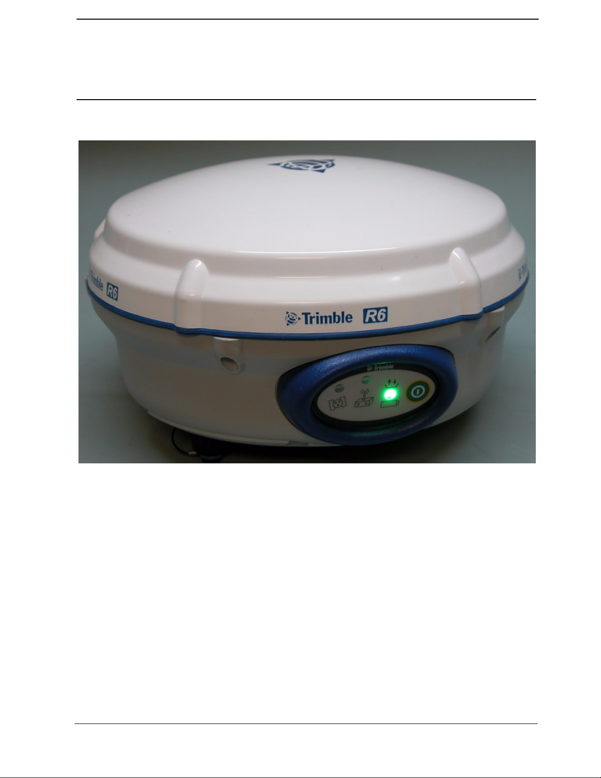
Trimble R6 / R6 (RoHS)
GPS Receivers
P/N 60775-SVC, Revision B Jan 2008
Page 2
SERVICE MANUAL
F
Release notice
This is the January 2008 release (Revision B) of the Trimble Trimble
R6 / R6 (RoHS) GPS Receivers Service Manual, part number 60775-
SVC. It applies to the Trimble R6 and R6 RoHS receivers.
Contacting Trimble Support
If you cannot find the information you need in this manual or in the
Trimble Service Provider Reference Manual (P/N 022480-068),
submit an inquiry to Trimble Support.
1. Go to www.trimble.com.
2. Click
3. Scroll to the bottom of the page that appears, and click the
4. Complete the Request Technical Support form that appears.
5. Click the
Legal Notices
© 2004–2007, Trimble Navigation Limited. All rights reserved.
Trimble, the Globe & Triangle logo, BlueCap, GPS Total Station,
and SiteVision are trademarks of Trimble Navigation Limited,
registered in the United States and in other countries.
AutoBase, CMR+, Maxwell, SiteNet, Survey Pro, Trimble Survey
Controller, TRIMCOMM, TRIMMARK, TRIMTALK, TSC1,
TSC2, TSCe, Zephyr, and Zephyr Geodetic are trademarks of
Trimble Navigation Limited.
The Bluetooth word mark and logos are owned by the Bluetooth
SIG, Inc. and any use of such marks by Trimble Navigation Limited
is under license.
Microsoft, Windows, and ActiveSync are either registered
trademarks or trademarks of Microsoft Corporation in the United
States and/or other countries.
All other trademarks are the property of their respective owners.
Disclaimer
Trimble Navigation Limited reserves the right to alter the
specification of this product and/or the content of this manual
without advance notification.
Notices
Class B Statement – Notice to Users. This equipment has been tested
and found to comply with the limits for a Class B digital device,
pursuant to Part 15 of the FCC rules. These limits are designed to
provide reasonable protection against harmful interference in a
residential installation. This equipment generates, uses, and can
radiate radio frequency energy and, if not installed and used in
accordance with the instructions, may cause harmful interference to
radio communication. However, there is no guarantee that
interference will not occur in a particular installation. If this
equipment does cause harmful interference to radio or television
reception, which can be determined by turning the equipment off and
on, the user is encouraged to try to correct the interference by one or
more of the following measures:
– Reorient or relocate the receiving antenna.
– Increase the separation between the equipment and the receiver.
– Connect the equipment into an outlet on a circuit different from
– Consult the dealer or an experienced radio/TV technician for help.
Changes and modifications not expressly approved by the
manufacturer or registrant of this equipment can void your authority
to operate this equipment under Federal Communications
Commission rules.
Support at the top of the screen.
submit an inquiry link.
Send button.
that to which the receiver is connected.
Trimble R6 / R6 (RoHS)
GPS Receivers
Europe
This product has been tested and found to comply with the
requirements for a Class B device pursuant to European
Council Directive 89/336/EEC on EMC, thereby
satisfying the requirements for CE Marking and sale
within the European Economic Area (EEA). Contains Infineon radio
module ROK 104001. These requirements are designed to provide
reasonable protection against harmful interference when the
equipment is operated in a residential or commercial environment.
Canada
This digital apparatus does not exceed the Class B limits for radio
noise emissions from digital apparatus as set out in the radio
interference regulations of the Canadian Department of
Communications.
Le présent appareil numérique n’émet pas de bruits radioélectriques
dépassant les limites applicables aux appareils numériques de Classe
B prescrites dans le règlement sur le brouillage radioélectrique édicté
par le Ministère des Communications du Canada.
Australia and New Zealand
This product conforms with the regulatory requirements of
the Australian Communications Authority (ACA) EMC
framework, thus satisfying the requirements for C-Tick
Marking and sale within Australia and New Zealand.
Taiwan – Battery Recycling Requirements
The product contains a removable Lithium-ion battery.
Taiwanese regulations require that waste batteries are
recycled.
Notice to Our European Union Customers
For product recycling instructions and more information,
please go to www.trimble.com/ev.shtml.
Recycling in Europe:
To recycle Trimble WEEE (Waste Electrical and Electronic
Equipment, products that run on electrical power.), Call +31
497 53 24 30, and ask for the “WEEE Associate”.
Or, mail a request for recycling instructions to:
Trimble Europe BV
c/o Menlo Worldwide Logistics
Meerheide 45
5521 DZ Eersel, NL
Declaration of Conformity
To view the Declaration of Conformity for this product:
1. Log in to the Partners website at http://partners.trimble.com.
2. In the panel on the left, click
3. Select the relevant file. It is in Adobe Portable Document Format
(PDF).
Restriction of Use of Certain Hazardous Substances in
Electrical and Electronic Equipment (RoHS)
This Trimble product complies in all material respects with
DIRECTIVE 2002/95/EC OF THE EUROPEAN PARLIAMENT
AND OF THE COUNCIL of 27 January 2003 on the restriction of
the use of certain hazardous substances in electrical and electronic
equipment (RoHS Directive) and Amendment 2005/618/EC filed
under C(2005) 3143, with exemptions for lead in solder pursuant
to Paragraph 7 of the Annex to the RoHS Directive applied.
Service.
P/N 60775-SVC, Revision B Jan 2008
Page 3

Contents
F
1 General Information and Safety . . . . . . . . . . . . . . . . . . . . . . . 8
Introduction. . . . . . . . . . . . . . . . . . . . . . . . . . . . . . . . . . . . . . . . . . . .8
Assumptions . . . . . . . . . . . . . . . . . . . . . . . . . . . . . . . . . . . . . . . . . . .8
Updating this manual . . . . . . . . . . . . . . . . . . . . . . . . . . . . . . . . . . . . . . .9
Related documentation . . . . . . . . . . . . . . . . . . . . . . . . . . . . . . . . . . . . . .9
Deciding what is serviceable . . . . . . . . . . . . . . . . . . . . . . . . . . . . . . . . . . .9
Possible loss of warranty . . . . . . . . . . . . . . . . . . . . . . . . . . . . . . . . . . . . 10
Removing and replacing parts . . . . . . . . . . . . . . . . . . . . . . . . . . . . . . . . . 10
Warnings and Cautions . . . . . . . . . . . . . . . . . . . . . . . . . . . . . . . . . . . . . 10
Electrostatic Discharge (ESD) . . . . . . . . . . . . . . . . . . . . . . . . . . . . . . . . . 11
Setting up an ESD-protected workstation . . . . . . . . . . . . . . . . . . . . . . . . 12
Battery safety . . . . . . . . . . . . . . . . . . . . . . . . . . . . . . . . . . . . . . . . . . 13
Rechargeable Lithium-ion batteries . . . . . . . . . . . . . . . . . . . . . . . . . . . . . . 13
Charging the Lithium-ion battery . . . . . . . . . . . . . . . . . . . . . . . . . . . . 14
Disposing of the rechargeable Lithium-ion battery . . . . . . . . . . . . . . . . . . . 14
The RoHS initiative . . . . . . . . . . . . . . . . . . . . . . . . . . . . . . . . . . . . . . 14
What RoHS means to Trimble. . . . . . . . . . . . . . . . . . . . . . . . . . . . . . 15
What RoHS means to Service . . . . . . . . . . . . . . . . . . . . . . . . . . . . . . 15
2 Specifications. . . . . . . . . . . . . . . . . . . . . . . . . . . . . . . . 17
General specifications . . . . . . . . . . . . . . . . . . . . . . . . . . . . . . . . . . . . . 18
Physical specifications . . . . . . . . . . . . . . . . . . . . . . . . . . . . . . . . . . . . . 18
Electrical specifications . . . . . . . . . . . . . . . . . . . . . . . . . . . . . . . . . . . . 20
Communications and data storage specifications . . . . . . . . . . . . . . . . . . . . . . . 20
3 Theory of Operation . . . . . . . . . . . . . . . . . . . . . . . . . . . . 21
The receiver generations . . . . . . . . . . . . . . . . . . . . . . . . . . . . . . . . . . . . 22
Key. . . . . . . . . . . . . . . . . . . . . . . . . . . . . . . . . . . . . . . . . . . . 22
Non RoHS receiver . . . . . . . . . . . . . . . . . . . . . . . . . . . . . . . . . . . 23
RoHS receiver . . . . . . . . . . . . . . . . . . . . . . . . . . . . . . . . . . . . . . 24
Features . . . . . . . . . . . . . . . . . . . . . . . . . . . . . . . . . . . . . . . . . . . . . 25
COCOM limits . . . . . . . . . . . . . . . . . . . . . . . . . . . . . . . . . . . . . . . . . 26
Environmental conditions . . . . . . . . . . . . . . . . . . . . . . . . . . . . . . . . . . . 26
Operating conditions . . . . . . . . . . . . . . . . . . . . . . . . . . . . . . . . . . . . . . 26
Avoiding electrical interference . . . . . . . . . . . . . . . . . . . . . . . . . . . . . . . . 27
Major circuit boards/assemblies . . . . . . . . . . . . . . . . . . . . . . . . . . . . . . . . 27
Bluetooth-I/O board . . . . . . . . . . . . . . . . . . . . . . . . . . . . . . . . . . . 28
Radio door assembly . . . . . . . . . . . . . . . . . . . . . . . . . . . . . . . . . . 29
Processor board . . . . . . . . . . . . . . . . . . . . . . . . . . . . . . . . . . . . . 31
Low Noise Amplifier (LNA) / Spirit antenna patch. . . . . . . . . . . . . . . . . . . 32
P/N 60775-SVC, Revision B Page 3 Trimble R6 / R6 (RoHS) GPS Receivers
Service Manual
Page 4

F
Keypad assembly . . . . . . . . . . . . . . . . . . . . . . . . . . . . . . . . . . . . 32
Front panel . . . . . . . . . . . . . . . . . . . . . . . . . . . . . . . . . . . . . . . . . . . 33
Button functions . . . . . . . . . . . . . . . . . . . . . . . . . . . . . . . . . . . . . 33
LED functions . . . . . . . . . . . . . . . . . . . . . . . . . . . . . . . . . . . . . . 34
Memory storage . . . . . . . . . . . . . . . . . . . . . . . . . . . . . . . . . . . . . . . . 35
Power input . . . . . . . . . . . . . . . . . . . . . . . . . . . . . . . . . . . . . . . . . . . 36
Battery charging and storage . . . . . . . . . . . . . . . . . . . . . . . . . . . . . . . . . . 36
Safety . . . . . . . . . . . . . . . . . . . . . . . . . . . . . . . . . . . . . . . . . . 36
Rechargeable Lithium-ion batteries . . . . . . . . . . . . . . . . . . . . . . . . . . . 37
Charging the battery . . . . . . . . . . . . . . . . . . . . . . . . . . . . . . . . . . . 37
Power output . . . . . . . . . . . . . . . . . . . . . . . . . . . . . . . . . . . . . . . . . . 39
Mounting the receiver on a range pole. . . . . . . . . . . . . . . . . . . . . . . . . . . . . 39
Other system components . . . . . . . . . . . . . . . . . . . . . . . . . . . . . . . . . . . 39
Radios . . . . . . . . . . . . . . . . . . . . . . . . . . . . . . . . . . . . . . . . . . 39
Application files . . . . . . . . . . . . . . . . . . . . . . . . . . . . . . . . . . . . . 41
Contents
4 Interfaces . . . . . . . . . . . . . . . . . . . . . . . . . . . . . . . . . . 43
Connections and ports . . . . . . . . . . . . . . . . . . . . . . . . . . . . . . . . . . . . . 43
Receiver connection pinouts . . . . . . . . . . . . . . . . . . . . . . . . . . . . . . . . . . 44
Port 1 . . . . . . . . . . . . . . . . . . . . . . . . . . . . . . . . . . . . . . . . . . 44
Port 2. . . . . . . . . . . . . . . . . . . . . . . . . . . . . . . . . . . . . . . . . . . 44
Power/Serial data cable port pinouts . . . . . . . . . . . . . . . . . . . . . . . . . . . . . . 45
5 Troubleshooting . . . . . . . . . . . . . . . . . . . . . . . . . . . . . . 46
Test when received . . . . . . . . . . . . . . . . . . . . . . . . . . . . . . . . . . . . . . . 46
Required service software . . . . . . . . . . . . . . . . . . . . . . . . . . . . . . . . . . . 47
Contact report information . . . . . . . . . . . . . . . . . . . . . . . . . . . . . . . . . . . 47
Possible failures and suggested solutions . . . . . . . . . . . . . . . . . . . . . . . . . . . 49
LED conditions . . . . . . . . . . . . . . . . . . . . . . . . . . . . . . . . . . . . . 49
External symptoms . . . . . . . . . . . . . . . . . . . . . . . . . . . . . . . . . . . 50
Power symptoms. . . . . . . . . . . . . . . . . . . . . . . . . . . . . . . . . . . . . 50
Satellites and signals symptoms . . . . . . . . . . . . . . . . . . . . . . . . . . . . . 51
Communications symptoms . . . . . . . . . . . . . . . . . . . . . . . . . . . . . . 52
Radio symptoms . . . . . . . . . . . . . . . . . . . . . . . . . . . . . . . . . . . . 53
6 Maintenance and Repair . . . . . . . . . . . . . . . . . . . . . . . . . . 57
Tools . . . . . . . . . . . . . . . . . . . . . . . . . . . . . . . . . . . . . . . . . . . . . . 57
Consumables. . . . . . . . . . . . . . . . . . . . . . . . . . . . . . . . . . . . . . . 57
Use and care . . . . . . . . . . . . . . . . . . . . . . . . . . . . . . . . . . . . . . . . . . 58
Underside of the receiver . . . . . . . . . . . . . . . . . . . . . . . . . . . . . . . . . . . . 58
Disassembling the unit . . . . . . . . . . . . . . . . . . . . . . . . . . . . . . . . . . . . . 59
Trimble R6 / R6 (RoHS) GPS Receivers Page 4 P/N 60775-SVC, Revision B
Service Manual
Page 5

F
Step 1. Removing the battery . . . . . . . . . . . . . . . . . . . . . . . . . . . . . . 60
Step 2. Removing the radio module . . . . . . . . . . . . . . . . . . . . . . . . . . . 61
Step 3. Removing the radome . . . . . . . . . . . . . . . . . . . . . . . . . . . . . . 62
Step 4. Removing the antenna patch. . . . . . . . . . . . . . . . . . . . . . . . . . . 64
Step 5. Removing the processor board . . . . . . . . . . . . . . . . . . . . . . . . . 67
Step 6. Removing the endoskeleton . . . . . . . . . . . . . . . . . . . . . . . . . . . 68
Step 7. Removing the keypad . . . . . . . . . . . . . . . . . . . . . . . . . . . . . . 70
Step 8. Removing the Bluetooth-I/O board . . . . . . . . . . . . . . . . . . . . . . . 71
Reassembling the unit . . . . . . . . . . . . . . . . . . . . . . . . . . . . . . . . . . . . . 72
Step 1. Replacing the keypad . . . . . . . . . . . . . . . . . . . . . . . . . . . . . . 72
Step 2. Replacing the Bluetooth-I/O board . . . . . . . . . . . . . . . . . . . . . . . 73
Step 3. Replacing the endoskeleton . . . . . . . . . . . . . . . . . . . . . . . . . . . 75
Step 4. Replacing the processor board. . . . . . . . . . . . . . . . . . . . . . . . . . 77
Step 5. Replacing the antenna patch. . . . . . . . . . . . . . . . . . . . . . . . . . . 78
Step 6. Replacing the radome . . . . . . . . . . . . . . . . . . . . . . . . . . . . . . 81
Step 7. Replacing the radio door assembly . . . . . . . . . . . . . . . . . . . . . . . 81
Step 8. Replacing the battery . . . . . . . . . . . . . . . . . . . . . . . . . . . . . . 82
Part replacement actions . . . . . . . . . . . . . . . . . . . . . . . . . . . . . . . . . . . . 82
Checking the unit . . . . . . . . . . . . . . . . . . . . . . . . . . . . . . . . . . . . . . . . 84
Contents
Radio Door Assemblies . . . . . . . . . . . . . . . . . . . . . . . . . . 85
Radio door compatibility and shielding methods . . . . . . . . . . . . . . . . . . . . . . . 85
Compatibility . . . . . . . . . . . . . . . . . . . . . . . . . . . . . . . . . . . . . . 85
Shielding methods . . . . . . . . . . . . . . . . . . . . . . . . . . . . . . . . . . . . 86
Integrated GSM radio: Overview. . . . . . . . . . . . . . . . . . . . . . . . . . . . . . . . 89
GSM door activation requirements . . . . . . . . . . . . . . . . . . . . . . . . . . . 90
Charging for the GSM door installation/activation . . . . . . . . . . . . . . . . . . . 90
Installing a GSM door: Overview . . . . . . . . . . . . . . . . . . . . . . . . . . . . 90
Repairing and installing the radio door assemblies . . . . . . . . . . . . . . . . . . . . . . 93
Tools required . . . . . . . . . . . . . . . . . . . . . . . . . . . . . . . . . . . . . . 93
Special configuration or other requirements . . . . . . . . . . . . . . . . . . . . . . 93
Disassembling the receiver . . . . . . . . . . . . . . . . . . . . . . . . . . . . . . . . . . . 94
Assembling the receiver . . . . . . . . . . . . . . . . . . . . . . . . . . . . . . . . . . . . 94
Installing the SIM card . . . . . . . . . . . . . . . . . . . . . . . . . . . . . . . . . 94
Installing a GSM cellular or UHF Transmit door assembly. . . . . . . . . . . . . . . 95
Testing GSM Cellular . . . . . . . . . . . . . . . . . . . . . . . . . . . . . . . . . . . . . 97
Registering the Trimble R6 Bluetooth device with the controller . . . . . . . . . . . 97
Connecting to the receiver and getting CSQ . . . . . . . . . . . . . . . . . . . . . . 97
Setting up a survey style. . . . . . . . . . . . . . . . . . . . . . . . . . . . . . . . . 97
Creating a new job to make a call from the receiver through the controller . . . . . . 98
P/N 60775-SVC, Revision B Page 5 Trimble R6 / R6 (RoHS) GPS Receivers
Service Manual
Page 6

F
The GSMcheck utility . . . . . . . . . . . . . . . . . . . . . . . . . . . . . . . . . . . . . 98
Running the test . . . . . . . . . . . . . . . . . . . . . . . . . . . . . . . . . . . . . 98
Supporting information: Test flow . . . . . . . . . . . . . . . . . . . . . . . . . . 100
Testing the receiver . . . . . . . . . . . . . . . . . . . . . . . . . . . . . . . . . . . . . . 103
Part Replacement Actions . . . . . . . . . . . . . . . . . . . . . . . . . . . . . . . . . . 103
Contents
7 Assembly Drawings . . . . . . . . . . . . . . . . . . . . . . . . . . . . 104
List of drawings . . . . . . . . . . . . . . . . . . . . . . . . . . . . . . . . . . . . . . . 104
Trimble R6 receiver (RoHS and non-RoHS) . . . . . . . . . . . . . . . . . . . . . 104
Trimble R6 receiver (non-RoHS) . . . . . . . . . . . . . . . . . . . . . . . . . . . 104
Trimble R6 receiver (RoHS) . . . . . . . . . . . . . . . . . . . . . . . . . . . . . 104
Drawings . . . . . . . . . . . . . . . . . . . . . . . . . . . . . . . . . . . . . . . . . . . 104
8 Adjustment and Verification . . . . . . . . . . . . . . . . . . . . . . . . 114
Test before shipping . . . . . . . . . . . . . . . . . . . . . . . . . . . . . . . . . . . . . 115
Inspection test . . . . . . . . . . . . . . . . . . . . . . . . . . . . . . . . . . . . . . . . 115
Seal integrity test . . . . . . . . . . . . . . . . . . . . . . . . . . . . . . . . . . . . . . . 115
Power Input test . . . . . . . . . . . . . . . . . . . . . . . . . . . . . . . . . . . . . . . 116
High and Low Voltage Input test (all) . . . . . . . . . . . . . . . . . . . . . . . . . 116
Operation test . . . . . . . . . . . . . . . . . . . . . . . . . . . . . . . . . . . . . . . . . 119
LED Operation test (all) . . . . . . . . . . . . . . . . . . . . . . . . . . . . . . . . 119
Power Button Operation test (all) . . . . . . . . . . . . . . . . . . . . . . . . . . . 119
Bluetooth Operation test and Radio Interface test . . . . . . . . . . . . . . . . . . 120
Memory test. . . . . . . . . . . . . . . . . . . . . . . . . . . . . . . . . . . . . . 121
Satellite Acquisition test. . . . . . . . . . . . . . . . . . . . . . . . . . . . . . . . 121
Configuration Retrieval test and Office Computer Communications test - Lemo port (all)123
Cable Communications test with a controller . . . . . . . . . . . . . . . . . . . . . 124
Office computer communications test, DB-9 serial port (All) . . . . . . . . . . . . 124
File Upload/Download test (all) . . . . . . . . . . . . . . . . . . . . . . . . . . . . 124
System test . . . . . . . . . . . . . . . . . . . . . . . . . . . . . . . . . . . . . . . . . . 125
Purpose of the test . . . . . . . . . . . . . . . . . . . . . . . . . . . . . . . . . . . 125
Components required . . . . . . . . . . . . . . . . . . . . . . . . . . . . . . . . . 126
Setting up the test components . . . . . . . . . . . . . . . . . . . . . . . . . . . . 127
Setting up the base. . . . . . . . . . . . . . . . . . . . . . . . . . . . . . . . . . . 127
Starting the base . . . . . . . . . . . . . . . . . . . . . . . . . . . . . . . . . . . . 128
Setting up the rover . . . . . . . . . . . . . . . . . . . . . . . . . . . . . . . . . . 129
Starting the rover . . . . . . . . . . . . . . . . . . . . . . . . . . . . . . . . . . . 129
Test range qualification . . . . . . . . . . . . . . . . . . . . . . . . . . . . . . . . 130
WINTXRX program. . . . . . . . . . . . . . . . . . . . . . . . . . . . . . . . . . 131
Trimble R6 / R6 (RoHS) GPS Receivers Page 6 P/N 60775-SVC, Revision B
Service Manual
Page 7

Contents
F
9 Service Software . . . . . . . . . . . . . . . . . . . . . . . . . . . . . . 132
Downloading the software . . . . . . . . . . . . . . . . . . . . . . . . . . . . . . . . . . 132
GPS Configurator utility . . . . . . . . . . . . . . . . . . . . . . . . . . . . . . . . . . . 132
Configuration Toolbox utility . . . . . . . . . . . . . . . . . . . . . . . . . . . . . . . . 133
Data Transfer utility . . . . . . . . . . . . . . . . . . . . . . . . . . . . . . . . . . . . . 136
Supervisor version of the WinFlash utility . . . . . . . . . . . . . . . . . . . . . . . . . . 136
Supervisor version of the WinFlash utility and new firmware . . . . . . . . . . . . 137
Available WinFlash operations . . . . . . . . . . . . . . . . . . . . . . . . . . . . 138
Installing a transmit frequency . . . . . . . . . . . . . . . . . . . . . . . . . . . . 141
Receiver configurations . . . . . . . . . . . . . . . . . . . . . . . . . . . . . . . . . . . 154
WinTXRX Radio Receive utility . . . . . . . . . . . . . . . . . . . . . . . . . . . . . . 157
WinPan utility . . . . . . . . . . . . . . . . . . . . . . . . . . . . . . . . . . . . . . . . 157
10 Replacement Parts List . . . . . . . . . . . . . . . . . . . . . . . . . . 166
Referenced assembly drawings. . . . . . . . . . . . . . . . . . . . . . . . . . . . . . . . 166
Required information when ordering parts. . . . . . . . . . . . . . . . . . . . . . . . . . 166
Naming conventions . . . . . . . . . . . . . . . . . . . . . . . . . . . . . . . . . . . . . 167
Product short name/description. . . . . . . . . . . . . . . . . . . . . . . . . . . . . . . . 167
Parts not listed . . . . . . . . . . . . . . . . . . . . . . . . . . . . . . . . . . . . . . . . 169
Parts list. . . . . . . . . . . . . . . . . . . . . . . . . . . . . . . . . . . . . . . . . . . . 169
A Recommended Repair Times . . . . . . . . . . . . . . . . . . . . . . . 175
B Seal Integrity Test . . . . . . . . . . . . . . . . . . . . . . . . . . . . . 176
Tools . . . . . . . . . . . . . . . . . . . . . . . . . . . . . . . . . . . . . . . . . . . . . 176
Assembling the Trimble Seal Integrity Kit. . . . . . . . . . . . . . . . . . . . . . . . . . 176
Hardware requirements . . . . . . . . . . . . . . . . . . . . . . . . . . . . . . . . 177
Installing the software . . . . . . . . . . . . . . . . . . . . . . . . . . . . . . . . . 177
Setting up communication. . . . . . . . . . . . . . . . . . . . . . . . . . . . . . . 177
Troubleshooting communication . . . . . . . . . . . . . . . . . . . . . . . . . . . 178
Testing vacuum . . . . . . . . . . . . . . . . . . . . . . . . . . . . . . . . . . . . . . . . 179
Examples of vacuum test results . . . . . . . . . . . . . . . . . . . . . . . . . . . 181
Testing pressure . . . . . . . . . . . . . . . . . . . . . . . . . . . . . . . . . . . . . . . 182
C RoHS Service Bulletin . . . . . . . . . . . . . . . . . . . . . . . . . . . 184
Restriction of hazardous substances . . . . . . . . . . . . . . . . . . . . . . . . . . . . . 184
P/N 60775-SVC, Revision B Page 7 Trimble R6 / R6 (RoHS) GPS Receivers
Service Manual
Page 8

Chapter 1
F
General Information and Safety
General Information and Safety 1
Q Introduction
Q Assumptions
Q Updating this manual
Q Related documentation
Q Deciding what is serviceable
Q Possible loss of warranty
Q Removing and replacing parts
Q Warnings and Cautions
Q Electrostatic Discharge (ESD)
Q Battery safety
Q Rechargeable Lithium-ion batteries
Q The RoHS initiative
This manual is a reference guide for service personnel at authorized Trimble Service
Providers or Trimble Service Centers. It describes how to correctly service, maintain, and
repair the new Trimble
®
R6 and Trimble R6 (RoHS compliant) GPS receivers.
Note – In this manual, “Trimble R6 receiver” or “the receiver” refers to both the RoHS
compliant and the non-compliant versions. If information applies to only one of these
receivers, this is clearly stated as “RoHS” or “non-RoHS”.
Introduction
This section describes the Service Manual for the Trimble R6 / R6 RoHS receivers.
• RoHS compliance is described, along with its relevance in Europe and China.
• RoHS compliant parts are described, along with when they can and can not be used.
• The part list shows the new parts and the older parts. The list specifies whether or
not the new part is fully backward compatible.
Assumptions
This manual assumes that you have attended the Trimble service training course for the
Trimble R6 receivers. It also assumes that you have appropriate knowledge and
understanding of:
• mechanical design, electronic theory, and general service procedures
• basic electronic test equipment such as volt-ohmmeters, oscilloscopes, frequency
generators, and power supplies
Trimble R6 / R6 (RoHS) GPS Receivers
Service Manual Page 8 P/N 60775-SVC, Revision B
Page 9

Chapter 1
F
• the operating system and software for the computer system that you use
Updating this manual
Photographs, illustrations, specifications, and other details in this manual were up to date
when the manual was released in December 2007. Any changes that may be needed will
be issued as supplementary or replacement pages, a Service Bulletin, other service
information, or as a new revision of this manual.
B
Related documentation
Tip – To keep a printed manual up to date, print any updates that you receive and insert them
at the relevant point in the manual.
You can download the latest version of this manual, as well as all Service Bulletins, User
Guides, and any Declaration of Conformity relevant to the receivers from the Trimble
Partners website. The files are in Adobe Portable Document Format (PDF).
General Information and Safety
Note – Read all relevant Service Bulletins before you repair or service this receiver.
To download a document for a receiver:
1. Go to the Trimble Partners website at http://partners.trimble.com.
2. Select Land Survey.
3. Enter your username and password and then click
4. On the left, click
5. From the list, select the required product (for example
6. Select Technical Support / Documentation.
7. Select the item that you want to download.
Info by Subject.
Deciding what is serviceable
The assembly drawings in this manual show the relationship between all assemblies that
are considered serviceable. Serviceable assemblies are defined as assemblies that can be
repaired by authorized Trimble Service Providers or at Trimble Service Center level. The
following factors determine whether an assembly is serviceable:
• The tools required to complete the repair.
Login.
Trimble R6).
• The time it takes to complete the work.
Trimble R6 / R6 (RoHS) GPS Receivers
P/N 60775-SVC, Revision B Page 9 Service Manual
Page 10

Chapter 1
F
Possible loss of warranty
If a Trimble product is not serviced properly, or if it is repaired by someone other than an
authorized technician, the manufacturer’s warranty on the product can become void. To
prevent loss of cover, always comply exactly with the instructions in this manual.
Removing and replacing parts
Note – The torque specifications, adhesives, and procedures specified in this manual are
essential to the proper operation of the GPS receiver.
To disassemble and reassemble the GPS receiver:
1. Consult the diagrams in Chapter 7, Assembly Drawings.
2. Carefully follow the procedures described in Chapter 6, Maintenance and Repair.
Apply the exact adhesives as specified, and torque only to the values indicated.
If you need to replace a part, see Chapter 10, Replacement Parts List.
General Information and Safety
Warnings and Cautions
Note – An absence of specific alerts does not mean that there are no safety risks involved.
Always follow the instructions that accompany a Warning or Caution. The information
they provide is intended to minimize the risk of personal injury and/or damage to the
equipment. In particular, observe safety instructions that are presented in the following
formats:
C
C
Warning – A Warning alerts you to a likely risk of serious injury to your person and/or damage
to the equipment. A warning identifies the nature of the risk and the extent of possible injury
and/or damage. It also describes how to protect yourself and/or the equipment from this risk.
Warnings that appear in the text are repeated at the front of the manual.
Caution – A Caution alerts you to a possible risk of damage to the equipment and/or loss of
data. A Caution describes how to protect the equipment and/or data from this risk.
Trimble R6 / R6 (RoHS) GPS Receivers
Service Manual Page 10 P/N 60775-SVC, Revision B
Page 11

Chapter 1
F
Electrostatic Discharge (ESD)
Note – For detailed information about ESD, refer to the Trimble Service Provider
Reference Manual (P/N 022480-068).
The Trimble R6 receivers were constructed in an ESD-protected environment. Most of the
semiconductor devices in the instrument are susceptible to ESD damage.
ESD is generated in many ways.
separation of materials, or the normal motion of people working with the device.
Depending on the magnitude of the charge, device substrates can be punctured or
destroyed by contact with, or by mere proximity to, a static charge. The result can be
immediate destruction, early failure of the device, or degradation of device performance.
To prevent static damage or destruction:
• Take adequate precautions when you handle or service equipment that contains
static-sensitive devices.
• Only attempt to service the circuitry in a static-sensitive device if you are
thoroughly familiar with industry-accepted techniques for handling such devices.
• Always take adequate measures to prevent the buildup of static charge on work
surfaces and on persons handling the GPS receiver.
General Information and Safety
For example, it can be the result of simple contact, the
Trimble R6 / R6 (RoHS) GPS Receivers
P/N 60775-SVC, Revision B Page 11 Service Manual
Page 12
Chapter 1
F
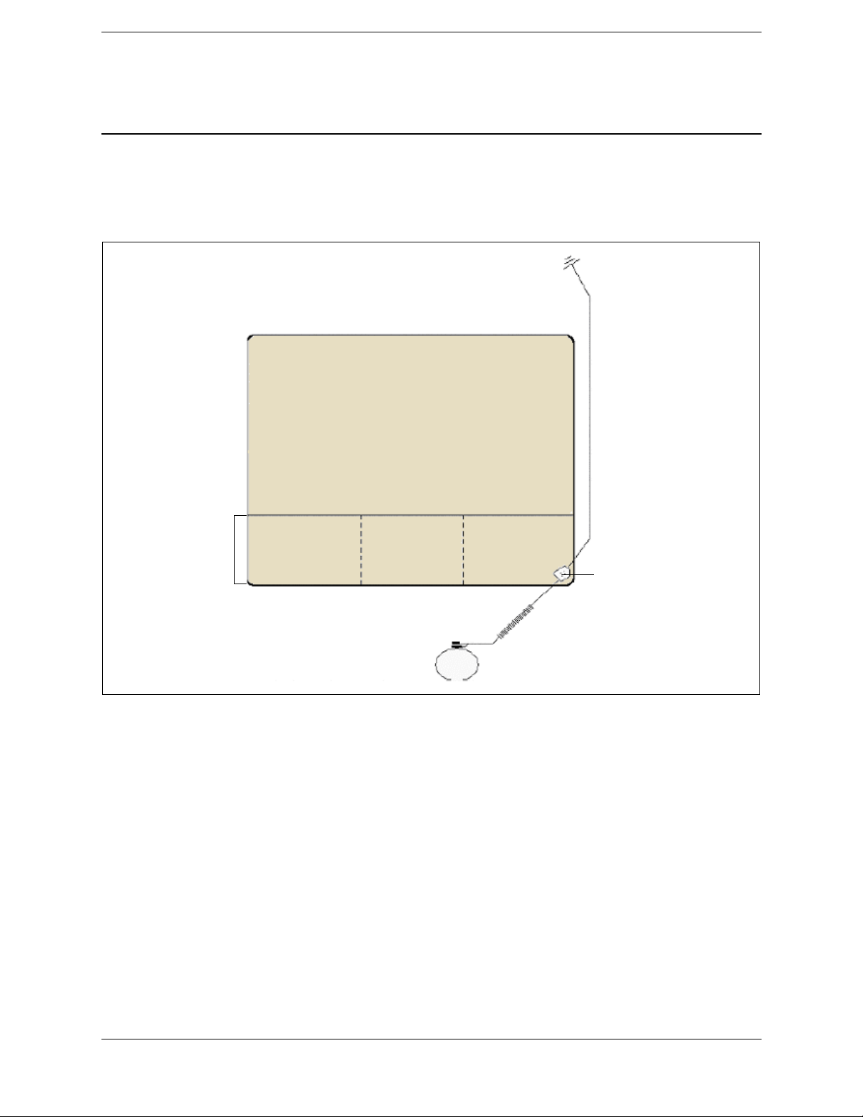
Setting up an ESD-protected workstation
1. Unroll the ESD field service workstation kit and place it, pocket side up, on the
workbench.
General Information and Safety
Electrical earth ground
connection
Mat grounding cable
Dissipative mat
Pockets
Figure 1.1 ESD workstation setup
2. Remove the mat grounding cable from the mat pocket.
3. Snap the end of the mat grounding cable onto the common point ground connection
on the mat.
4. Connect the other end of the cable to an electrical earth ground, such as a third wire
utility ground, a cold water pipe, or a ground rod.
5. Use the common point ground connection to plug the wrist strap cable into the mat
grounding cable.
Note – Put on the wrist strap. The wrist strap must fit snugly. To adjust it, unclasp the
buckle latch, adjust the size, and re-clasp the latch.
It is now safe to handle components and printed circuit assemblies on the mat.
Snap-on common point
ground connection
Wrist strap cable
Wrist strap
Note – Always repackage all ESD-sensitive components before you disconnect the wrist
strap.
Trimble R6 / R6 (RoHS) GPS Receivers
Service Manual Page 12 P/N 60775-SVC, Revision B
Page 13

Chapter 1
F
Battery safety
C
C
C
C
C
Warning – Use only the specified battery charger to charge the battery pack. Other battery
chargers may cause the battery pack to catch alight or to rupture.
Warning – Do not cover the battery charger while the battery pack is being recharged. The
charger must be able to dissipate heat adequately. Coverings such as blankets or clothing may
cause the charger to overheat. Overheating may damage the charger and cause a fire.
Warning – Do not recharge the battery pack in a humid or dusty place, in direct sunlight, or
near a heat source. Do not recharge the battery pack when it is wet. If you do, you may receive
electric shocks or burns, or the battery pack may overheat or catch alight.
Warning – Never burn or heat the battery. Doing so may cause the battery to leak or rupture. A
leaking or ruptured battery can cause serious injury.
Warning – Before you store the battery pack or battery charger, cover the contact points with
insulation tape. If you do not cover the contact points, the battery pack or charger may shortcircuit, causing fire, burns, or damage to the instrument.
General Information and Safety
C
C
Warning – Do not short-circuit the contacts in the battery pack. The battery pack has an autoreset circuit breaker, but short circuits may cause the battery pack to catch alight or to burn you.
Caution – Handle, charge, and dispose of the battery in this unit only in strict accordance with
the instructions that are provided in the product documentation. Use only the recommended
battery charger and be sure to follow the manufacturer’s instructions exactly. Failure to follow
those instructions may result in a fire and/or burns and other injuries.
Rechargeable Lithium-ion batteries
The Trimble R6 receivers use a rechargeable Lithium-ion battery as the primary power
source.
C
Warning – Do not damage the battery. A damaged battery can cause an explosion or fire, and
can result in personal injury and/or property damage. To prevent injury or damage:
– Do not use or charge the battery if it appears to be damaged. Signs of damage include, but
are not limited to, discoloration, warping, and leaking battery fluid.
– Do not expose the battery to fire, high temperature, or direct sunlight.
– Do not immerse the battery in water.
– Do not use or store the battery inside a vehicle during hot weather.
– Do not drop or puncture the battery.
– Do not open the battery or short-circuit its contacts.
Trimble R6 / R6 (RoHS) GPS Receivers
P/N 60775-SVC, Revision B Page 13 Service Manual
Page 14

Chapter 1
F
C
C
Warning – Avoid contact with the battery if it appears to be leaking. Battery fluid is corrosive,
and contact with it can result in personal injury and/or property damage.To prevent injury or
damage:
– If the battery leaks, avoid contact with the battery fluid.
– If battery fluid gets into your eyes, immediately rinse your eyes with clean water and seek
medical attention. Do not rub your eyes!
– If battery fluid gets onto your skin or clothing, immediately use clean water to wash off the
battery fluid.
Warning – Charge and use the battery only in strict accordance with the instructions. Charging
or using the battery in unauthorized equipment can cause an explosion or fire, and can result in
personal injury and/or equipment damage. To prevent injury or damage:
– Do not charge or use the battery if it appears to be damaged or leaking.
– Charge the battery only in a Trimble product that is specified to charge it. Be sure to follow all
instructions that are provided with the battery charger.
– Discontinue charging a battery that gives off extreme heat or a burning odor.
– Use the battery only in Trimble equipment that is specified to use it.
– Use the battery only for its intended use and according to the instructions in the product
documentation.
General Information and Safety
Charging the Lithium-ion battery
The battery is supplied partially charged. Charge the battery completely before using it for
the first time. If the battery has been stored for longer than three months, charge it before
use. To ensure a full charge and to optimize the battery life, leave the batteries to charge
overnight.
Disposing of the rechargeable Lithium-ion battery
Discharge the battery before disposing of it. When disposing of the battery, be sure to do
so in an environmentally sensitive manner. Adhere to any local and national regulations
concerning battery disposal or recycling.
The RoHS initiative
In July 2006, the European Union restricted the hazardous material content within new
products being sold. Primarily this was an effort to reduce lead within products. Many
parts within electronic devices contain lead, such as solder on PC boards or within IC's.
After the RoHS implementation, manufacturers were required to use alternate materials
and soldering methods. Products that were sold before the July 2006 date, have been
grand-fathered in, and are not subject to RoHS. Service parts specifically for these
products containing lead are permitted as well. Only newly created products intended for
sale after the July 2006 date are subject to RoHS.
Trimble R6 / R6 (RoHS) GPS Receivers
Service Manual Page 14 P/N 60775-SVC, Revision B
Page 15

Chapter 1
F
What RoHS means to Trimble
Trimble has made the commitment to create all new GPS products as lead free and
certified RoHS compliant. This includes older products which have been selling prior to
RoHS. You will start to see many of the older products converted into RoHS compliant
versions. Even though these are older products and it is not required, it is an extremely
worthwhile endeavor.
What RoHS means to Service
There are several very complex issues around the RoHS initiative. The Service Provider
must understand and follow these rules:
• Only lead free solder may be used on RoHS compliant products. Most GPS Service
Providers have been using Silver solder for several years (AG/SN). Make sure you
ONLY use Silver solder for ANY GPS products.
• Parts meant for non RoHS products must NOT be used on RoHS products. Use only
those parts shown in the part list for a specific product.
• Parts meant for a RoHS product may not be compatible with a non RoHS product.
Use only those parts shown in the part list for a specific product. If the part works in
both products, the part list will state that.
• Radio doors, radio boards, and Bluetooth
must also pass type approval. Some parts may not be used in other products due to
non compliance with Country regulations. Use only those parts shown in the part
list for a specific product.
General Information and Safety
®
boards pose special problems as they
• Within the part lists, the general rule to identify whether a product is RoHS
compliant or not is to look at the short name. For instance, NetRS, R6, and R8GNSS
are non-compliant products. NetRSR, R6R, and R8GNSSR are RoHS compliant
(shown by the last letter R).
• It is highly recommended that Service Providers have separate inventory location
for lead and lead free parts. This might mean a different cabinet or shelf. It is also
highly recommended to have RoHS labels available to attach to the individual part.
Green dots are a good solution and will help to quickly identify RoHS compliant
parts.
• RoHS service parts will be a phase in process for non RoHS products. Use the
original part defined for the non RoHS product first. Once these parts are consumed,
the new RoHS part will phase in as long as it is FULLY backwards compatible. The
old part numbers will then be inactivated. Please, ALWAYS refer to the latest part
list.
• RoHS compliant PC boards may be identified by these symbols:
• In mid 2007, China will launch its own RoHS initiative. The products that have
been certified as RoHS compliant will comply with specific country regulations.
Trimble R6 / R6 (RoHS) GPS Receivers
P/N 60775-SVC, Revision B Page 15 Service Manual
Pb
e1
Page 16

Chapter 1
F
• Service parts are defined as:
– SPR (Service Part Red) which is allowed in the EU to service an existing
product
– SPG (Service Part Green) which conforms to RoHS.
For more information, see Appendix C, RoHS Service Bulletin.
General Information and Safety
Trimble R6 / R6 (RoHS) GPS Receivers
Service Manual Page 16 P/N 60775-SVC, Revision B
Page 17

Chapter 2
F
Specifications
Specifications 2
Q General specifications
Q Physical specifications
Q Electrical specifications
Q Communications and data storage specifications
This chapter contains the specifications for the Trimble R6 / R6 (RoHS) GPS receivers.
The specifications are extracted from the relevant receiver Data Sheet.
Trimble R6 / R6 (RoHS) GPS Receiver
P/N 60775-SVC, Revision B Page 17 Service Manual
Page 18

Chapter 2
F
Specifications
General specifications
Feature Specification
Keyboard and display On/Off key for one button startup using AutoBase™ technology
LED indicators For satellite tracking, radio link reception, and power monitoring
Receiver type Fully integrated “Smart” GPS antenna
Physical specifications
Feature Specification
Dimensions (WxH) 19 cm (7.5 in) x 11.5 cm (4.4 in) including connectors
Weight 1.35 kg (2.97 lb) with internal battery, internal radio, standard UHF antenna
3.71 kg (8.18 lbs) entire RTK rover including batteries, range pole, controller, and
bracket
Temperature
Operating
Storage
Humidity 100%, condensing
Water resistance IPX7 for submersion to depth of 1 m (3.28 ft)
Shock and vibration
Shock, non operating
Shock, operating
Vibration
Measurements Trimble R-Track technology for GLONASS support
1
–40 °C to +65 °C (–40 °F to +149 °F)
–40 °C to +75 °C (–40 °F to +167 °F)
Tested and meets the following environmental standards:
Designed to survive a 2 m (6.6 ft) pole drop onto concrete
MIL-STD-810F, Fig.514.5C-17
To 40 G, 10 msec, saw-tooth
MIL-STD-810F, FIG.514.5C-1
Advanced Trimble Maxwell
High-precision multiple correlator for GNSS pseudo-range measurements
Unfiltered, unsmoothed pseudo-range measurements data for low noise, low multipath
error, low time domain correlation, and high dynamic response
Very low noise GNSS carrier phase measurements with <1 mm precision in a 1 Hz
bandwidth
Proven Trimble low elevation tracking technology
Signal-to-Noise ratios reported in dB-Hz
Proven Trimble low-elevation tracking technology
72 Channels:
– GPS L1 C/A Code, L1/L2 Full Cycle Carrier
– GLONASS L1 C/A Code, L1 P Code, L2 P Code, L1/L2 Full Cycle Carrier
– SBAS WAAS / EGNOS support
™
Custom GPS chip
Trimble R6 / R6 (RoHS) GPS Receiver
Service Manual Page 18 P/N 60775-SVC, Revision B
Page 19

Chapter 2
F
Feature Specification
Code differential GPS
positioning
Horizontal accuracy
Vertical accuracy
WAAS differential
positioning accuracy
Static and FastStatic GPS
Surveying
Horizontal
Verti cal
Kinematic surveying
Horizontal
Verti cal
Initialization time
Initialization reliability
1
The receiver will operate normally to –40 °C, but the Bluetooth module and internal batteries are rated to –20 °C.
2
Accuracy and reliability may be subject to anomalies such as multipath, obstructions, satellite geometry, and atmospheric conditions.
Always follow recommended practices.
3
Depends on WAAS/EGNOS/GLONASS system performance.
4
May be affected by atmospheric conditions, signal multipath, and satellite geometry. Initialization reliability is continuously monitored
to ensure highest quality
2
±(0.25 m + 1 ppm) RMS, ± (9.84 in + 1 ppm) RMS
±(0.50 m + 1 ppm) RMS, ± (19.68 in + 1 ppm) RMS
Typically <5 m (16.40 ft) 3D RMS
3
2
±(5 m + 0.5 ppm) RMS, ± (196.7 in + 1 ppm) RMS
±(5 m + 1 ppm) RMS, ± (196.7 in + 1 ppm) RMS
2
±(10 mm + 1 ppm) RMS, ± (0.38 in +1 ppm) RMS
±(20 mm + 1 ppm) RMS, ± (0.78 in +1 ppm) RMS
<25-30 seconds typical
4
>99.9% typical
Specifications
Note – Glonass signal reception is optional.
Trimble R6 / R6 (RoHS) GPS Receiver
P/N 60775-SVC, Revision B Page 19 Service Manual
Page 20

Chapter 2
F
Specifications
Electrical specifications
Feature Specification
Power, internal 11 to 28 V DC external power input with over-voltage protection on Port 1 (7-pin
Lemo)
Battery Rechargeable, removable 7.4 V, 2.4 Ah Lithium-ion battery in internal battery
compartment
Power consumption <3.1 W, in RTK mode with internal radio
Operating time on internal
battery
450 MHz
450 MHz
GSM /GPRS
Certification Class B Part 15, 22, 24 FCC certification, 850 / 1900 MHz.
Receive only: 5.3 hours; varies with temperature
Receive and transmit: 3.5 hours; varies with temperature and wireless data rate
3.8 hours; varies with temperature
Class 10 GSM/GPRS module
CE mark approval
C-tick approval
Communications and data storage specifications
Feature Specification
Communications
Port 1 (7-pin Lemo)
Port 2 (DSub 9-pin)
Bluetooth
Integrated radios Fully integrated, fully sealed internal 450 MHz, TX, RX, or Tx/Rx
450 MHz receiver/transmitter radio power
output
External GSM/GPRS, cellular phone
support
Receiver position update rate 1 Hz, 2 Hz, 5 Hz, and 10 Hz positioning
Data storage (11 MB internal memory) 302 hours of raw observables based on recording data from 6
Data Input and Output CMRII, CMR+
Outputs NMEA, GSOF, and RT17
Carrier Supports BINEX and smoothed carrier
1
Bluetooth type approvals are country specific. Contact your local Trimble office or representative for more information.
2
Varies with terrain and operating conditions.
3-wire serial (7-pin Lemo)
Full RS-232 serial (DSub, 9-pin)
Fully integrated, fully sealed 2.4 GHz Bluetooth
Fully integrated, fully sealed internal GSM/GPRS option (R8 GNSS
receiver only)
Transmit power: 0.5 W
2
Range
Supported for direct dial and Internet-based VRS correction streams
External cellphone support for GSM/GPRS/CDPD modems for RTK
and VRS operations
satellites at 15 second intervals
: 3–5 km typical; 10 km optimal
™, RTCM 2.1, RTCM 2.3, RTCM 3.0
1
Trimble R6 / R6 (RoHS) GPS Receiver
Service Manual Page 20 P/N 60775-SVC, Revision B
Page 21

Chapter 3
F
Theory of Operation
Theory of Operation 3
Q The receiver generations
Q Features
Q COCOM limits
Q Environmental conditions
Q Operating conditions
Q Avoiding electrical interference
Q Major circuit boards/assemblies
Q Front panel
Q Memory storage
Q Power input
Q Power output
Q Power output
Q Mounting the receiver on a range pole.
Q Other system components
This chapter describes the Trimble R6 / R6 (RoHS) receiver for GPS surveying
applications. The receiver incorporates a GPS antenna, receiver, internal radio, and battery
in a rugged lightweight unit that is ideally suited as an all-on-the-pole RTK (Real-Time
Kinematic) rover.
Three LEDs show the status of satellite tracking, radio reception, and power. Bluetooth®
wireless technology provides cable-free communications between the receiver and the
controller. The receiver provides 72 channels for L1/L2 GPS and L1/L2 GLONASS
(optional), and WAAS/EGNOS support. For details of received signal options for each
receiver, see The receiver generations, page 22. Raw or positional data can be stored
internally or to the handheld controller for RTK OTF or postprocessed applications.
Trimble R6 / R6 (RoHS) GPS Receiver
P/N 60775-SVC, Revision B Page 21 Service Manual
Page 22

Chapter 3
F
Theory of Operation
The receiver generations
The tables show four main categories of information:
• Product. Product part number and description, sales status, common name used in
this manual, and RoHS compliance.
Note – All products shown below are current.
• GNSS (Global Navigation Satellite System). Signals that can be used by the
receiver.
• Radio. Capabilities for the internal radio and the service part number for the door
assembly.
• Markings. Physical differences between the receivers that help identify them
Key
Column Value Meaning
Tx Op Transmit-capable; enabling the TX function is an upgrade
Color B Blue
Color LG Light grey
Color D Dark blue
RoHS compliant N
Y
GLNSS Op Optional
No
Yes
Trimble R6 / R6 (RoHS) GPS Receiver
Service Manual Page 22 P/N 60775-SVC, Revision B
Page 23

Chapter 3
F
Non RoHS receiver
Product GNSS Internal
P/N
60275-00 R6
60275-62 R6
60275-64 R6
60275-66 R6
60275-70 R6 Rest of World
60275-71 R6 US cellular
Description
no radio
410–420 MHz
TX-capable RX
radio
430–450 MHz
TX-capable RX
radio
450–470 MHz
TX-capable RX
radio
cellular radio
radio
Theory of Operation
Markings
radio
Common
name
RoHS compliant
L1
L2
WAAS
GLNS
RX
TX
R6 N 333Op x x 57880-00S D LG
R6 N 3 3 3 Op 3 Op 57880-62S or
R6 N 333Op 3 Op 57880-64S
R6 N 3 3 3 Op 3 Op 57880-66S or
R6 N 333Op 33 57880-70S D LG
R6 N 3 3 3 Op 3 3 57880-71S D LG
Radio Bd /
Door P/N
58707-62S
or
58707-64S
58707-66S
(see
Figure 3.1)
Bumper Color
D LG
DLG
D LG
Housing
color
Trimble R6 / R6 (RoHS) GPS Receiver
P/N 60775-SVC, Revision B Page 23 Service Manual
Page 24

Chapter 3
F
RoHS receiver
Product GNSS Internal
P/N
60775-00 R6 RoHS
60775-62 R6 RoHS
60775-64 R6 RoHS
60775-66 R6 RoHS
60775-70 R6 RoHS GSM
60775-71 R6 RoHS GSM
Description
no radio
410–420 MHz
TX-capable RX
radio
430–450 MHz
TX-capable RX
radio
450–470 MHz
TX-capable RX
radio
Rest of World
cellular radio
US cellular radio
Theory of Operation
Markings
radio
Common
name
R6R Y 333Op x x 59400-00S D LG
R6R Y 3 3 3 Op 3 Op 59400-62S or
R6R Y 333Op 3 Op 59400-64S or
R6R Y 3 3 3 Op 3 Op 59400-66S or
R6R Y 333Op 33 59400-70S D LG
R6R Y 3 3 3 Op 3 3 59400-71S D LG
RoHS compliant
L1
L2
WAAS
GLNS
RX
TX
Radio Bd /
Door P/N
64235-62S
64235-64S
64235-66S
(see
Figure 3.1)
Bumper
color
D LG
DLG
D LG
Housing
color
Trimble R6 / R6 (RoHS) GPS Receiver
Service Manual Page 24 P/N 60775-SVC, Revision B
Page 25
Chapter 3
F
Theory of Operation
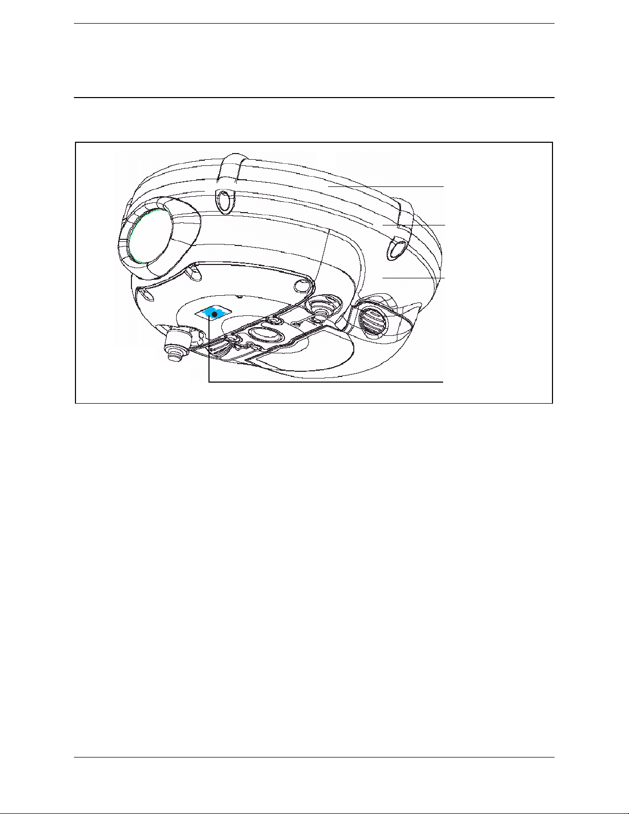
Housing color
Bumper color
Housing
Figure 3.1 Location of markings
Features
The receiver provides the following features:
• Centimeter-accuracy, real-time positioning with RTK/OTF data, up to 10 Hz
position updates
• Submeter-accuracy, real-time positioning using pseudo range corrections
• Adaptive dual-frequency RTK engine
• GLONASS capability
• WAAS/EGNOS capability
• 11 MB internal memory
• Automatic OTF (On-The-Fly) initialization while moving
• Single Lithium-ion rechargeable battery
• Cable-free Bluetooth communications with the Trimble Attachable Control Unit
(ACU), TSC2
Label
®
controller, TCU, or TSCe™ controller with BlueCap® module
Trimble R6 / R6 (RoHS) GPS Receiver
P/N 60775-SVC, Revision B Page 25 Service Manual
Page 26

Chapter 3
F
• Two RS-232 serial ports for (one Lemo and one DB-9):
–NMEA output
– RTCM SC-104 input
– Trimble format (CMR and CMR+) input
• One TNC port for connecting to a radio antenna
COCOM limits
The U.S. Department of Commerce requires that all exportable GPS products contain
performance limitations so that they cannot be used in a manner that could threaten the
security of the United States. The following limitations are implemented on the
Trimble R6 GPS receiver:
• Immediate access to satellite measurements and navigation results is disabled when
the receiver's velocity is computed to be greater than 1000 knots, or its altitude is
computed to be above 18,000 meters.
Theory of Operation
• The receiver continuously resets until the COCOM situation is cleared.
Environmental conditions
Although the receiver has a waterproof housing, reasonable care should be taken to protect
the unit. Avoid exposure to extreme environmental conditions, including:
• Water immersion
• Heat greater than 65 °C (149 °F)
• Cold less than -40 °C (-40 °F)
• Corrosive fluids and gases
Operating conditions
The receiver is designed to withstand the rough treatment that typically occurs in the field.
However, the receiver is a high-precision electronic instrument and should be treated with
reasonable care.
C
Warning – Operating or storing the receiver outside the specified temperature range can
damage it. See Chapter 2, Specifications.
Trimble R6 / R6 (RoHS) GPS Receiver
Service Manual Page 26 P/N 60775-SVC, Revision B
Page 27

Chapter 3
F
High-power signals from a nearby radio or radar transmitter can overwhelm the receiver
circuits. This does not harm the instrument, but it can prevent the receiver electronics from
functioning correctly. Avoid using the receiver within 400 meters of powerful radar,
television, or other transmitters. Low-power transmitters, such as those used in cellular
phones and two-way radios, do not normally interfere with receiver operations.
Avoiding electrical interference
Avoid the following sources of electrical and magnetic noise:
• Gasoline engines (spark plugs)
• Televisions and office computer monitors
• Alternators and generators
• Electric motors
• Equipment with DC-to-AC converters
• Fluorescent lights
Theory of Operation
• Switching power supplies
Major circuit boards/assemblies
Although the receiver has 11 MB of internal data memory, it is the controller (TCU or
TSC2) that should be used as the primary data storage for RTK survey styles.
Bluetooth technology offers a cable-free operation when epoch intervals are set to 1 per 5
seconds or longer. If the epoch interval is set to a faster rate (for example, 1 per second),
the receiver must be cabled to the controller. The range of Bluetooth communications is
about 5 meters (15 feet) depending on external noise or interference levels. In some cases,
interference from several Bluetooth capable device in close proximity can cause this
distance to decrease. Bluetooth technology is a cable-free system, not a long distance
remote control system.
The receiver contains the following five major circuit boards/assemblies:
• Bluetooth-I/O board, page 28
• Radio door assembly, page 29
• Processor board, page 31
• Low Noise Amplifier (LNA) / Spirit antenna patch, page 32
• Keypad assembly, page 32
Trimble R6 / R6 (RoHS) GPS Receiver
P/N 60775-SVC, Revision B Page 27 Service Manual
Page 28

Chapter 3
F
Bluetooth-I/O board
You can replace this board (P/N 55155-10S RoHS and P/N 55155-00S non-RoHS), which
has the following properties and features:
• Port 2 (RS-232 port through a DB-9 connector). Allows data communications and
external sensor input or output.
• Port 1 (Lemo-style 7 female connector). Allows data I/O operations. This is the
primary port between the receiver and the controller (TCU or TSC2) for cable type
operations. It is also the port used to upgrade firmware or options within the
receiver. Connecting the receiver to an office computer uses the standard survey
download cable (P/N 32345) and AC adaptor (P/N 48800-00 or 30413).
Note – Newer cables and AC adapters are available and are RoHS compatible. However,
P/N 55155-10S is not backward compatible for use in the Trimble R6 receiver. Trimble
will not assume any liability for a third-party servicer who uses incorrect parts for a
repair.
• Bluetooth TX/RX wireless communications system. Sends and receives data
between the receiver and the controller (ACU, TCU, TSC2, or the TSCe with
BlueCap module). Includes the TX/RX antenna for Bluetooth. The figure on
page 58 shows the radiation area. Other electronic equipment in use nearby may
interfere with the communications link. Do not add large metallic labels to this area.
The Bluetooth primary communications frequency is 2.4 Ghz and is allowed in
most countries.
Theory of Operation
C
• Interface connection between the keypad cable and the processor board.
• Port 1 and 2 protection circuitry (identical to that in the 5800 GPS receiver). A PTC
takes a sample of current supplied. If the current is too high (for example, in
over-voltage, shorted, or reverse polarity conditions), the device heats up rapidly
and causes a crowbar action to shut off supplied power. Remove the power source
and correct the problem. The unit automatically resets as the temperature of the PTC
decreases to normal.
Caution – The PTC is always in circuit and can withstand a maximum of 35 VDC. If you
connect a higher voltage, the PTC will be destroyed and will not protect the receiver. The PTC
is extremely useful in that it does not offer a voltage drop like a diode. This is especially
important when the primary power source is a battery.
Trimble R6 / R6 (RoHS) GPS Receiver
Service Manual Page 28 P/N 60775-SVC, Revision B
Page 29

Chapter 3
F
Radio door assembly
A radio door assembly (P/N 57880-XXS, 59400-XXS, 58707-XXS, or 64235-XXS) is
present only in radio-equipped versions of the receiver.
• For the Trimble R6 receiver (non-RoHS), use only P/N 57880-XXS or
P/N 58707-XXS.
• For the Trimble R6 receiver (RoHS), use only P/N 59400-XXS or P/N 64235-XXS.
Do not interchange radios between receivers.
There are no serviceable parts in a radio door, which must be replaced as an assembly. A
few external repairs (for example, the dustcap and the labels) are possible.
In Receive mode, the radio door assembly receives correction information from a
transmission source, converts the information into a defined digital format, and sends the
information to the processor board. The user can select which frequency, channel spacing,
baud rate, and packet type the radio door assembly receives, in the configuration setup.
In Transmit mode (if available), the correction data string is sent from the processor board
to the transmitter for broadcast. The radio transmitter generates the carrier frequency and
then modulates this in a packet format for broadcast.
Theory of Operation
The customer can select a frequency defined in the transmit frequency list. The customer
can also modify any of the receive frequencies, but is not allowed to change the transmit
frequencies.
The Service Provider can create a file of customer-specified frequencies to be installed by
the customer, and can also directly change the transmit frequencies of a locally-connected
GPS receiver.
Each version of the UHF radio door assembly has a frequency range of 20 MHz.
Versi on Frequency range
-62 410–430 MHz
-64 430–450 MHz
-66 450–470 MHz
The highest frequency of one version is the same as the lowest frequency of the next.
Consequently, if you select the same channel spacing for both, you can use a version -62
radio door assembly with 430 MHz selected in place of a version -64 radio door assembly
with 430 MHz selected, or a version -64 radio door assembly with 450 MHz selected in
place of a version -66 radio door assembly with 450 MHz selected.
The radio door assemblies are transmit-capable, although this function is considered an
upgrade. The radio door assemblies:
• are compatible with the TRIMMARK™ 3, High Power Base, PDL450, SiteNet450,
and any of the TX/RX radios in the older R8, R7, 5800, and 5700 receivers
Trimble R6 / R6 (RoHS) GPS Receiver
P/N 60775-SVC, Revision B Page 29 Service Manual
Page 30

Chapter 3
F
• may have compatibility issues with an older radio, such as a 4700, 4800, or
TRIMMARK 2e radio
• are not compatible with a TRIMMARK 1 or TRIMMARK 2 radio
Changing the version
Trimble does not recommend that a customer or a Service Provider changes from one
version of radio door assembly to another, for the following reasons:
• The internal connector on the radio is not intended for multiple insertions or
extractions. It will break.
• The seal integrity of the whole GPS receiver is compromised when the radio is
removed. A customer does not have the facilities to test seal integrity.
• Trimble has no way of knowing which radio version is being used for a specific
product serial number (SN). This leads to confusion and mistakes, and the very real
possibility of the warranty being voided.
• If the unit is outside of warranty, the customer can purchase another radio, which
must be installed by the Service Provider. There are hardware limitations to this, so
be very careful, especially with the GSM and 900 MHZ doors.
Theory of Operation
C
Versi on Details
-70 and -71 These are GSM radios, and each version operates in a specific region. The radio door assembly
-6X These radios can transmit correction information at 0.5 W. Data is not streamed from the external
53620-XXS Radio door assemblies in this series are not compatible with Trimble R6, Trimble R8 GNSS, or
Caution – Because of installation problems and country regulation issues, Trimble does not
sell radio doors to end users. Trained Service Providers must comply with country regulations
and install the correct radio only in defined and accepted receivers. Installing a radio in a non
specified GPS product or device voids any warranty of the radio and of the GPS product. It also
subjects the Service Provider to penalties set forth by various government agencies. Trimble
shall assume no liability for radios used in non-authorized products.
The key features of each version of the radio door assembly are shown below.
• For the Trimble receiver R6 (non-RoHS), use only P/N 57880-XXS or
P/N 58707-XXS.
• For the Trimble R6 receiver (RoHS), use only P/N 59400-XXS or P/N 64235-XXS.
Radio doors P/N 59400-6XS and P/N 57880-6XS will be phased out in the near future
enables the receiver to communicate correction information using a cellular phone network.
Typically, a VRS™ network connection is also used, but is not essential.
radio port, but instead is directed internally to the TX-capable radio. The TX-capable radio then
transmits the information for approximately 3–4 km (2–3 miles).
SPS880 receivers.
.
Trimble R6 / R6 (RoHS) GPS Receiver
Service Manual Page 30 P/N 60775-SVC, Revision B
Page 31

Chapter 3
F
Versi on Details
57880-XXS These radios are now considered obsolete. They are not compatible with the earlier Trimble R8,
SPS780, or 5800 receivers.
Use them only on the Trimble R6 (P/N 60275-XX) or Trimble R8 GNSS (P/N 60158-XX) non-RoHS
receivers.
59400-XXS These radios are RoHS compliant.
You can use them with the Trimble R6 RoHS receivers, though some limitations apply.
58707-XXS New version radios with significant enhancements and lower price. Only for R6.
64235-6XS Currently, RoHS version of radio for Trimble R6 RoHS receiver only.
Theory of Operation
Processor board
Note – This processor board (P/N 53646-01S) is not compatible for use in the Trimble R8,
SPS780, or 5800 receivers. The board is fully backward compatible for use in the
Trimble R6 / R6 RoHS / R8 GNSS receivers and will replace P/N 53646-00S.
You can replace this board, which:
• contains all circuitry for the various power supply voltages, and controls the power
input and output.
• has the main CPU for interacting with a computer or handheld device.
• down-converts and processes GPS, GLONASS, and WAAS/EGNOS information
from the LNA/antenna patch. Enabling GLONASS, signals is optional for the
Trimble R6 receiver.
• uses correction information collected by the radio module to correct GNSS
information and so increase the accuracy and repeatability of a point.
• has 11 MB of memory which it uses to store program, data, application file, and
configuration information.
If you replace the processor board, configure the replacement board to the specific
receiver:
1. Make a note of the receiver serial number and part number, and the radio door
assembly part number.
2. Contact Trimble for the necessary password(s).
3. Change the serial number from 0000000000 to the serial number of the unit under
repair.
4. Install a password option, and configure the board as a Trimble R6 or R8 GNSS.
5. Install any appropriate upgrade options, such as Date option or UHF TX enable.
Trimble R6 / R6 (RoHS) GPS Receiver
P/N 60775-SVC, Revision B Page 31 Service Manual
Page 32

Chapter 3
F
Low Noise Amplifier (LNA) / Spirit antenna patch
You can replace this assembly—P/N 59153-10S, or P/N 55175-10S (Trimble R6 receiver).
Note – P/N 59153-10S is fully backward compatible with the Trimble R6 receiver, and will
replace P/N 55175-10S.
Each P/N has the following properties and features:
• The antenna and low noise amplifier for reception are presented as raw information
to the processor board through two separate semi-rigid coax cables. The L1 cable
carries data received from the Satellite L1 transmission (C/A and GLONASS L1
signals). The L2 cable carries data received from the L2 or WAAS satellite
transmission.
Note – If the L1 reception fails, the system will not function because L2 reception requires
the L1 signal.
• The semi-rigid coax cables are sold separately.
• To replace the LNA/antenna patch, replace it as an assembly. This LNA/antenna
patch is not compatible with earlier Trimble R8, SPS780, or 5800 receivers.
Theory of Operation
Keypad assembly
You can replace the keypad assembly (P/N 50522-00S), which has:
• One button to turn the receiver on and off and to perform a soft or hard reset.
• Three LEDs to show the status of satellite tracking, radio reception, and power
input. See Figure 3.2, page 33. The flex cable from the keypad connects to the I/O
board and then to the processor board.
The same keypad is used on the Trimble R8, SPS780, and 5800 receivers.
Trimble R6 / R6 (RoHS) GPS Receiver
Service Manual Page 32 P/N 60775-SVC, Revision B
Page 33

Chapter 3
F
Front panel
Theory of Operation
SV tracking
Radio
Power status
Figure 3.2 Keypad on front panel
Power button
LEDs
Button functions
The single power button E on the receiver does the following:
• Turns on or turns off the receiver.
Note – When you turn off a Trimble R6 receiver, you must wait 10 seconds before you turn
it on again.
• Other functions, as described below:
– “Press” means press the button and release it immediately
– “Press and hold” means press the button and then hold it down for the specified
time
Action Power button
Turn on the receiver Press
Turn off the receiver Press and hold for 2 seconds
Trimble R6 / R6 (RoHS) GPS Receiver
P/N 60775-SVC, Revision B Page 33 Service Manual
Page 34

Chapter 3
F
Action Power button
Delete the ephemeris file Press and hold for 15 seconds. See 15-second reset below.
Reset the receiver to factory defaults Press and hold for 15 seconds. See 15-second reset below.
Delete application files Press and hold for 30 seconds. See 30-second reset below.
15-second reset
1. With the receiver turned off, press and hold the power button
LEDs turn on and then turn off. The Power LED turns on and then turns off about 5
seconds after you press the button. After 15–20 seconds, the Power LED turns on.
2. Release
3. Wait a few moments and then continue normal operation.
30-second reset
1. With the receiver turned off, press and hold the power button
all LEDs turn on and then turn off. The Power LED turns on and then turns off about
5 seconds after you press the button. After 15–20 seconds, the Power LED turns on.
E . The other LEDs turn on and then turn off.
Theory of Operation
E for 15 seconds. All
E . After 15 seconds,
2. Continue to hold
3. Release
then stays on.
E . All LEDs turn on and then off. The Power LED blinks a few times and
E . After 30–40 seconds, all LEDs turn off.
LED functions
The three LEDs on the front panel of the receiver indicate various operating conditions.
LED states
Generally, a lit or slowly flashing LED indicates normal operation, an LED that is flashing
quickly indicates a condition that may require attention, and an unlit LED indicates that no
operation is occurring. Possible LED states are shown below.
The term … means that the LED …
Slow flash alternates on/off for 500 milliseconds.
Fast flash alternates rapidly on/off for 100 milliseconds
On is lit and steady
Off is unlit
Trimble R6 / R6 (RoHS) GPS Receiver
Service Manual Page 34 P/N 60775-SVC, Revision B
Page 35

Chapter 3
F
Theory of Operation
LED flash patterns
Possible flash patterns that indicate states of receiver operation are shown below. If a
column shows “N/A”, that specific LED may or may not be on, but it is not relevant to that
particular mode.
Receiver mode Power LED
Green
Receiver OFF OFF OFF OFF
Receiver ON:
Healthy power ON N/A N/A
Low power Fast flash N/A N/A
Tracking <4 SVs ON N/A Fast flash
Tracking >4 SVs ON N/A Slow flash
Logging data internally Flashes off every 3
seconds
Transmitting internally N/A Flashes off when
Receiving valid data
packets
No data packets ON OFF N/A
Receiver in Monitor ON Slow flash ON
ON Slow flash N/A
Radio LED
Green
N/A N/A
transmitting
Satellite LED
Amber
N/A
Memory storage
The receiver has 11 MB of internal data memory storage, although the primary memory
storage is the TSC2 or TCU controller. For the RTK survey method, the controller must be
attached to the rover.
Depending on which version of GPS receiver you have, when the receiver is connected by
cable or by Bluetooth wireless technology to a Trimble controller, you can log GPS data
from the receiver to the controller, or to a PC card inserted in the controller. When you use
a Trimble controller, you do not use the controls on the receiver. Instead, you use the
controller functions to set logging options, to specify file names, and to control when data
is stored in job files, which can then be transferred to the office. For more information on
logging data from a receiver using a Trimble controller, refer to the user guide for your
controller.
To reset the receiver to its factory default settings, make sure that the receiver is turned off
and then press and hold the power button
for 15 seconds.
E
Trimble R6 / R6 (RoHS) GPS Receiver
P/N 60775-SVC, Revision B Page 35 Service Manual
Page 36

Chapter 3
F
Power input
The receiver can be powered by its internal battery, by an external power source connected
to Port 1, or by both. Typically, one internal Lithium-ion 2.4 Ah battery provides
approximately 5 hours of operation during an RTK survey using the internal receive radio.
When transmit mode is in use, the operating time is approximately 3 hours.
When external voltage of less than 15 VDC is applied, the receiver turns on automatically.
This is different from the earlier Trimble R8, SPS780, or 5800 receivers.
If an external power source is connected to Port 1, it is used in preference to the internal
battery. When there is no external power source connected, or if the external power supply
fails, the internal battery is automatically used. The receiver system includes rechargeable
Lithium-ion batteries (P/N 54344), and a dual battery, 2 Pack Charger (P/N 61114-00).
The batteries charge sequentially and take approximately three hours each to fully charge
from a full discharged state.
Battery charging and storage
Theory of Operation
C
C
C
C
C
C
Safety
Warning – Use only the specified battery charger to charge the battery pack. Other battery
chargers may cause the battery pack to catch alight or to rupture.
Warning – Do not cover the battery charger while the battery pack is being recharged. The
charger must be able to dissipate heat adequately. Coverings such as blankets or clothing may
cause the charger to overheat. Overheating may damage the charger and cause a fire.
Warning – Do not recharge the battery pack in a humid or dusty place, in direct sunlight, or
near a heat source. Do not recharge the battery pack when it is wet. If you do, you may receive
electric shocks or burns, or the battery pack may overheat or catch alight.
Warning – Never burn or heat the battery. Doing so may cause the battery to leak or rupture. A
leaking or ruptured battery can cause serious injury.
Warning – Before you store the battery pack or battery charger, cover the contact points with
insulation tape. If you do not cover the contact points, the battery pack or charger may shortcircuit, causing fire, burns, or damage to the instrument.
Warning – Do not short-circuit the contacts in the battery pack. The battery pack has an
auto-reset circuit breaker, but short circuits may cause the battery pack to catch alight or to
burn you.
Trimble R6 / R6 (RoHS) GPS Receiver
Service Manual Page 36 P/N 60775-SVC, Revision B
Page 37

Chapter 3
F
C
C
Caution – Handle, charge, and dispose of the battery in this unit only in strict accordance with
the instructions that are provided in the product documentation. Use only the recommended
battery charger and be sure to follow the manufacturer’s instructions exactly. Failure to follow
those instructions may result in a fire and/or burns and other injuries.
Rechargeable Lithium-ion batteries
The Trimble R6 GPS receivers uses a rechargeable Lithium-ion battery as the primary
power source.
Warning – Do not damage the battery. A damaged battery can cause an explosion or fire, and
can result in personal injury and/or property damage. To prevent injury or damage:
– Do not use or charge the battery if it appears to be damaged. Signs of damage include, but
are not limited to, discoloration, warping, and leaking battery fluid.
– Do not expose the battery to fire, high temperature, or direct sunlight.
– Do not immerse the battery in water.
– Do not use or store the battery inside a vehicle during hot weather.
– Do not drop or puncture the battery.
– Do not open the battery or short-circuit its contacts.
Theory of Operation
C
C
Warning – Avoid contact with the battery if it appears to be leaking. Battery fluid is corrosive,
and contact with it can result in personal injury and/or property damage.To prevent injury or
damage:
– If the battery leaks, avoid contact with the battery fluid.
– If battery fluid gets into your eyes, immediately rinse your eyes with clean water and seek
medical attention. Do not rub your eyes!
– If battery fluid gets onto your skin or clothing, immediately use clean water to wash off the
battery fluid.
Warning – Charge and use the battery only in strict accordance with the instructions. Charging
or using the battery in unauthorized equipment can cause an explosion or fire, and can result in
personal injury and/or equipment damage. To prevent injury or damage:
– Do not charge or use the battery if it appears to be damaged or leaking.
– Charge the battery only in a Trimble product that is specified to charge it. Be sure to follow all
instructions that are provided with the battery charger.
– Discontinue charging a battery that gives off extreme heat or a burning odor.
– Use the battery only in Trimble equipment that is specified to use it.
– Use the battery only for its intended use and according to the instructions in the product
documentation.
Charging the battery
The battery is supplied partially charged. Charge the battery completely before using it for
the first time. If the battery has been stored for longer than three months, charge it before
use. To ensure a full charge and to optimize the battery life, leave the batteries to charge
overnight.
Trimble R6 / R6 (RoHS) GPS Receiver
P/N 60775-SVC, Revision B Page 37 Service Manual
Page 38

Chapter 3
F
Note – All battery types discharge over time when they are not being used. Batteries also
discharge faster in colder temperatures.
To protect the battery from deep discharge (5 volts or less), the receiver stops drawing
power when the battery pack discharges to 5.9 volts. The receiver shuts down with no
damage to receiver or battery. (The deep discharge protection circuit can be triggered if a
battery with a low charge is left for several weeks.)
To try to recover a battery that has reached the deep discharge level, place it in the 2-pack
charger. This may not always succeed. If the battery reaches this deep discharge state, it
sets a protection circuit, also called the sleep or protection mode. A Service Provider can
“wake up” the battery and recharge it. There is no damage or limiting of the life
expectancy on the battery but the customer must replace the battery or send it to a Service
Provider to recover it. Trimble recommends the following for optimal performance and to
extend the life of the batteries:
• Fully charge all new batteries before use and when the system is first received. The
batteries are shipped at less than 100% charge. If you use them in this depleted state,
it will reduce their life expectancy. To ensure a full charge, and to optimize the life
of the battery, leave it to charge overnight.
Theory of Operation
• Do not allow the batteries to discharge below 5 volts.
• Keep all batteries on continuous charge in the 2-pack charger when not in use.
Batteries may be kept on the charger indefinitely without damage to the batteries.
• Do not store batteries in the external charger unless power is applied. If you must
store the batteries, fully charge them before storing, place them in a plastic bag, at
room temperature, then fully recharge them at least once every three months.
Battery charging is done externally using the 2-pack charger. You cannot charge the
internal Lithium-ion battery by applying more than 15 volts to Port 1. The 2-pack charger
is included with all new receiver systems.
Only a Trimble branded battery is authorized for use within Trimble products. Use of any
other battery limits or voids any warranty for the product. The battery generally carries a
1-year warranty. Warranty is not offered on non-Trimble batteries, batteries that have been
misused (used outside of their stated operating specifications), or for normal wear and tear.
The Lithium-ion battery has a finite number of discharge/charge cycles in its lifetime. As
the number of cycles approaches the maximum, the support capacity decreases. A new
battery may have 6-hour support capacity, but an older battery may only have 1 hour. This
is normal wear and tear. There are many variables when assessing the life of a battery.
With average/medium use, the battery should reach 1-hour support time after about 3
years. Using the batteries for UHF transmission reduces this life expectancy to about 2
years.
Trimble R6 / R6 (RoHS) GPS Receiver
Service Manual Page 38 P/N 60775-SVC, Revision B
Page 39

Chapter 3
F
Power output
The receiver does not output power from either of its two ports. The internal Lithium-ion
battery is not charged when external power is applied to the receiver.
Mounting the receiver on a range pole.
Theory of Operation
1. Thread the receiver onto the range pole.
2. Attach the controller bracket to the pole.
3. Insert the controller into the bracket. No cabling is required for a Trimble controller.
Other system components
You can use the following optional components with the receiver.
Radios
Radios are the most common data link for RTK (Real-Time Kinematic) surveying. The
receiver is available with an optional internal radio in either the 450 MHz or GSM band.
You can also connect an external radio to either serial port, whether the internal radio is
installed or not. The receiver supports the following Trimble base radios with the internal
450 MHz radio (assuming each of the receivers has the firmware version to support the
communication):
•TRIMMARK™ 3 radio
• TRIMMARK™ IIe radio (limited compatibility)
•SiteNet 450
• PDL450
Trimble R6 / R6 (RoHS) GPS Receiver
P/N 60775-SVC, Revision B Page 39 Service Manual
Page 40

Chapter 3
F
•HPB
Internal radio setup
To configure the optional internal radio, use one of the following utilities:
• GPS Configurator utility
• WinFlash utility
You can also change the receiver setting using the Trimble Survey Controller™ software.
For more information, refer to the GPS Configurator Help, the WinFlash Help, or the
Trimble Survey Controller User Guide. By default, the internal radio has only a few “test”
frequencies installed at the factory. The customer can add receive-only frequencies. To add
transmit frequencies directly into a connected unit, the customer must install a file that is
generated and sent to them by the Service Provider or Trimble. The UHF Transmit switch
must be enabled before you can add transmit frequencies. Use the WinFlash utility to
program licensed frequencies before you use the receiver.
Cellular modems and external radios
Theory of Operation
Instead of the internal radio, you can use a cellular modem or external radio as the data
communications link. To connect a cellular modem to the receiver, you need the
following:
• A receiver
• A cellular modem, or a cellular phone that can transmit and receive data
• A serial (cellular phone-to-DB-9) cable. This cable is supplied with the cellular
modem or phone.
Note – For more information, refer to the document Using Cellular and CDPD Modems
for RTK, which is available from the Trimble website.
Port 2 of the receiver supports full RS-232 protocol, and should function correctly with
most cellular phone cables. Some cellular units may require custom cabling. For more
information on using a cellular modem as a data link, refer to the Trimble Survey
Controller User Guide.
GSM cellular radios (P/N 59400-70 and P/N 59400-71) can be installed in the radio bay to
provide a completely integrated solution.
To connect an external radio modem to the receiver, you need the following:
• A receiver
• An external radio capable of receiving and decoding Trimble data packets
• A serial cable for either Port 1 or Port 2 of the receiver, as supplied by the radio
manufacturer
• A radio mount for the range pole
Trimble R6 / R6 (RoHS) GPS Receiver
Service Manual Page 40 P/N 60775-SVC, Revision B
Page 41

Chapter 3
F
Application files
An application file does not have to contain all of these records. When you apply an
application file, any option that is not included in the records in the file remains at its
current setting. For example, if you apply an application file that only specifies the
elevation mask to use, all other settings remain as they were before the application file was
applied. You can store up to twenty different application files in the receiver. You can
apply an application file's settings at the time it is transferred to the receiver or at any time
afterwards.
Special application files
The receiver has three special application files, which control important aspects of receiver
configuration.
• Default application file
The Default application file (Default.cfg) contains the original receiver
configuration, and cannot be changed. This file configures the receiver after it is
reset. To reset the receiver, hold down
option in the GPS Configurator utility. Although you cannot change or delete the
Default application file, you can use a Power Up application file to override any or
all of the default settings.
Theory of Operation
for at least 15 seconds, or use the reset
E
• Current application file
The Current application file (Current.cfg) reflects the current receiver configuration.
Whenever you change the receiver's configuration, either in real time or by applying
an application file, the Current file changes to match the new configuration. You
cannot delete the Current file or change it directly, but every change to the receiver's
current configuration is applied to the Current file as well. When you switch off the
receiver then turn it on again, all the settings from the Current application file are
applied, so you do not lose any changes that you have made. The only exceptions
are the following logging parameters:
– Logging rate
– Position rate
– Elevation mask
These parameters are always reset to the factory default values whenever the
receiver is switched off.
• Power Up application file
The Power Up application file (Power_up.cfg) is used to set the receiver to a
specific configuration whenever the unit is powered up. You can specify that the
receiver is reset to defaults before the Power Up settings are applied. This ensures
that restarting the receiver always resets it to factory defaults prior to applying the
Power Up application file. Alternatively, you can specify that the Power Up settings
are applied immediately after the Current application file's settings have been
Trimble R6 / R6 (RoHS) GPS Receiver
P/N 60775-SVC, Revision B Page 41 Service Manual
Page 42

Chapter 3
F
applied. Restarting the receiver results in a configuration that uses your default
settings for the options you define in the Power Up file, but the current settings for
all other options.
By default, there is no Power Up application file on the receiver. If you want to use
a Power Up application file, you need to create an application file in Configuration
Toolbox and make sure that the Auto Power Up file option is selected in the File
page. When you transfer this file to the receiver, it is transferred with the name
Power_up.cfg, and becomes the new Power Up file. The Power Up file is the only
special application file that you can overwrite or delete from the receiver.
Applying application files
An application file's settings do not affect the receiver's configuration until you apply the
application file. You can do this at the same time that you save the file. Alternatively, you
can save the file on the computer or in the receiver, then open it later and apply its settings.
Storing application files
You can store application files that you create in Configuration Toolbox on both your
receiver and computer. For example, each file can represent a different user sharing the
same receiver, or a particular mode of operation or survey style. Saving application files
on your computer as well as in your receiver is optional, but it is useful because:
Theory of Operation
• it gives you a permanent copy of the settings you have sent to a receiver, for audit or
your own reference
• you can use the same file to identically configure multiple receivers
• you can use an existing application file as a template to create other application files
with similar settings.
Naming application files
The file name that you use to store the application file in the computer and the name under
which the file is stored in the receiver are always the same. This makes recognizing and
keeping track of your application files easier. If you change the name of the file on the
receiver, this changes the file name used to store the application file on your computer.
Similarly, if you change the file name on the computer, the name of the file in the receiver
will change.
Trimble R6 / R6 (RoHS) GPS Receiver
Service Manual Page 42 P/N 60775-SVC, Revision B
Page 43

Chapter 4
F
Interfaces
Interfaces 4
Q Connections and ports
Q Receiver connection pinouts
Q Power/Serial data cable port pinouts
Connections and ports
Port 1
Figure 4.1 Lower housing
Each receiver port or connector is marked with an icon to indicate its main function, as
shown below.
Icon Name Connections Details
Port 1 Device
Computer
External radio
Power in only
7-pin 0-shell Lemo connector.
Supports RS-232 comms.
Radio connector
Port 2
Trimble R6 / R6 (RoHS) GPS Receiver
P/N 60775-SVC, Revision B Page 43 Service Manual
Page 44

Chapter 4
F
Icon Name Connections Details
Port 2 Device
Computer
External radio
RADIO Radio communications
antenna
Receiver connection pinouts
Port 1
7
1
2
3
5
Pin Pinout function
6
1 Ground
2 Ground
3 TX3_232
4 RTS/TXD
5CTS/RXD
4
6 + Power in
7 TX3_232
Interfaces
DB-9 male connector.
Full 9-pin RS-232 comms.
No power in or out.
Connects a radio antenna to the receiver internal radio.
A “rubber duck” antenna is supplied with the system for units
with internal 450 MHz, and GSM radios.
Not required if you use an external radio receiver.
A full size “whip” antenna may be used instead, although
primarily for Base operation.
Port 1 – 7-pin Lemo
Port 2
78
9
6
2
1
3
5
4
Trimble R6 / R6 (RoHS) GPS Receiver
Service Manual Page 44 P/N 60775-SVC, Revision B
Pin Pinout function
Port 2 – DB-9
1 DCD
2 RXD
3TXD
4 DTR
5 Signal ground
6 DSR
7RTS
8 CTS
9 Ring indicator
Page 45

Chapter 4
F
Power/Serial data cable port pinouts
This table shows the pinouts for the data-I/O cable (P/N 18532), which is supplied with the
receiver. This assumes that the cable is attached to the connector labelled Port 2.
DB-9 female
9-pin
Pin Function Pin Function
1-6 DCD5_232 4 DTR5_232
2 RX5_232 3 TX5_232
3 TX5_232 2 RX5_232
4 DTR5_232 1-6 DCD5_232
5GND 5 GND
7 RTS5_232 8 CTS5_232
8 CTS5_232 7 RTS5_232
9 no connection RI5_232 9
This data cable may be used for firmware upgrades and other computer functions with the
receiver. Power must be supplied to the receiver through Port 1, or from the internal
battery.
DB-9 female
9-pin
Interfaces
The following table shows the pinouts for the power/serial data cable (P/N 32345), which
is optional for use with the receiver. This cable may be used for firmware upgrades
through the receiver Port 1, while also supplying external power. This assumes that the
cable is attached to the connector labeled Port 1.
Lemo 0-shell connector
7-pin
Pin Function Pin Color Function Color Function
1GND
2 GND
3 TX3_232
4 RTS/TXD
5CTS/RXD
6 PWR_IN
7 RX3_232
Direction DE9-F connector
7 Cond
↔
→
→
→
←
←
←
5 Brown Signal ground
2 Orange TXD
8 Blue RTS
7GreenCTS
Red Power IN (+)
3YellowTXD
Power lead
2 Cond
Black V-OU T
Trimble R6 / R6 (RoHS) GPS Receiver
P/N 60775-SVC, Revision B Page 45 Service Manual
Page 46

Chapter 5
F
Troubleshooting
Troubleshooting 5
Q Test when received
Q Required service software
Q Contact report information
Q Possible failures and suggested solutions
This chapter describes how to troubleshoot the Trimble R6 GPS receivers. It lists the tools
needed for troubleshooting, describes how to analyze faults in the unit, and provides a list
of error codes and their meanings.
Test when received
Test the unit when it is received and again before shipping it back to the customer (see Test
before shipping, page 115).
Name Element Pass 3
Inspection test Check for cracks and physical damage and missing parts and record the details
Record all parts included with shipment.
Seal Integrity test Check seal integrity of unit
Power Input test High Voltage Input test
Low Voltage Input test
Power consumption test
Battery Charge Status test
Battery Only test
Battery Voltage Input test
Trimble R6 / R6 (RoHS) GPS Receiver
Service Manual Page 46 P/N 60775-SVC, Revision B
Page 47

Chapter 5
F
Name Element Pass 3
Operation test LED Operation test
Power Button Operation test
Bluetooth Operation test
Radio Interface test
Memory test
Satellite Acquisition test
Configuration Retrieval test
Office Computer (PC) Communications test - Lemo port
PC Communications test - DB-9 serial port
Cable Communications test with TSC2 controller or TSCe controller
PC Communications test - DB-9 serial port
File Upload/Download test
Performance test System test (may not be required unless there is a radio short range failure)
GSM test GSM radio only
Troubleshooting
Required service software
To service these receivers, you require one or more of the following software applications
or utilities:
• GPS Configurator
• Configuration Toolbox
• Data Transfer
• WinFlash (Supervisor)
•WinTXRX
•WinPan
• GSMcheck (GSM radio only) See page 98.
For more information, see Chapter 9, Service Software.
Contact report information
This manual covers the Trimble R6 GPS receivers, both the RoHS compliant and the
non-compliant versions. Many of the new RoHS compliant parts may be used for the
non-compliant receiver. Make certain that you use the required part. For example, the
sensor board for a Trimble R6 GPS receiver is not the same as that used in a Trimble R8 or
SPS780 receiver.
Trimble R6 / R6 (RoHS) GPS Receiver
P/N 60775-SVC, Revision B Page 47 Service Manual
Page 48

Chapter 5
F
There is no upgrade available to convert a Trimble R6 GPS receiver to any other receiver
type. You may be able to upgrade some options on some receivers—please discuss this
with a Trimble Sales Representative.
A new Lithium-ion battery with a 2400 mAh capacity (P/N 54344) is shipped with the
system. This battery is fully backward-compatible for use in earlier Trimble R8, SPS780,
5800, Trimble R7, SPS770, and 5700 receivers and in the TSC1™ controller. Older 2-pack
chargers, which have no microswitch in the battery bay, cannot fully charge newer
batteries.
Note – When ordering parts, you must use the parts list in Chapter 10, Replacement Parts
List
When contacting Trimble Support with a problem or on a warranty claim, please provide
details of:
• The problems or failure symptoms described by the customer.
• Whether you or the Dealer verified the customer’s complaint. What other problems
did you find?
• How you tried to correct the above failures.
Troubleshooting
• Which part actually corrected the failure(s).
Please list the solutions in the same order as the failures.
This information provides a starting point for a more complete report.
Example of a complete report
The following example shows typical information that Trimble needs in order to help you.
The customer has tried to install a radio that is not allowed in the Trimble R6 receiver, or
that was possibly shipped from the factory by mistake.
Item Details
Receiver Trimble
Fault category Internal radio
Failure No transmission
Product P/N 60275-66
Product SN 4627056522
Radio door P/N 57880-90
Sales order number A670597
SWO SWO345332
Customer fault Cannot transmit corrections.
SP verified fault Confirmed that radio cannot establish communications. Error message.
R6
Error message that radio is not supported.
Trimble R6 / R6 (RoHS) GPS Receiver
Service Manual Page 48 P/N 60775-SVC, Revision B
Page 49

Chapter 5
F
Item Details
What was tried Checked configuration with WinFlash utility.
UHF Transmit is enabled.
Using Lithium-ion battery (P/N 54344).
Solution Hardware is not compatible with the receiver. The 900 MHz radio operates only with an
SPS880 receiver.
Discuss with customer where -66 radio door is. Found and installed. All Trimble
Specifications tested and passed.
Sales order shows that original Trimble R6 receiver was shipped with P/N 57880-66
door.
Troubleshooting
Possible failures and suggested solutions
The following symptoms may indicate failures in the receiver. Some possible solutions are
suggested.
LED conditions
Condition Possible cause Solution
The SV Tracking LED is lit
solidly and the
Logging/Memory LED is
flashing slowly
The SV Tracking LED is not
flashing
The receiver is in monitor mode,
ready for new firmware to be
loaded or new options to be added
The receiver is tracking fewer than
four satellites
– Turn the receiver off, wait 10 seconds and
then turn on the receiver again.
– Load the latest version of the firmware;
(download from
www.trimble.com/support.html).
– Wait until the SV Tracking LED is flashing
slowly.
– Make sure that the semi-rigid coax cables
are connected securely.
Try the suggested solutions in the order given. Solutions that do not require you to open
the receiver are listed first.
Trimble R6 / R6 (RoHS) GPS Receiver
P/N 60775-SVC, Revision B Page 49 Service Manual
Page 50

Chapter 5
F
Troubleshooting
External symptoms
Symptom Without opening the unit,
try the following
LEDs turn on then turn off – Replace the battery.
– Use external power.
– Reflash the firmware.
– Check the keypad operation.
Receiver rattles – Attach any loose dust caps.
Water in receiver – Verify that there is no corrosion on the
Open the unit and then
try the following
– Replace the keypad.
– Check the battery door foam pads.
Replace the door if the pads are worn.
– Check all cables. Replace if required.
– Test the Lemo connections on the
Bluetooth-I/O board.
– Replace the Bluetooth-I/O board. Replace
the processor (sensor) board.
– Tie down any loose cables.
boards. If one board has corrosion, replace
that board; if all boards have corrosion,
replace the entire unit.
– Completely clean all boards with isopropyl
alcohol. Use de-ionized water or denatured
alcohol to clean off any residue.
– Carefully inspect the perimeter gasket and
the keypad. Do a seal integrity test.
Power symptoms
Symptom Without opening the unit,
try the following
Receiver does not turn on – Check the battery fuses.
– Recharge or replace the batteries.
– Use external power.
– Reflash the firmware.
– Check all cables; test with different
cables.
Receiver does not
respond
– Turn off the receiver, wait 10 seconds
and then turn it on again.
– Soft reset the receiver.
– Hard reset the receiver.
Open the unit and then
try the following
– Test the Lemo connection on the
Bluetooth-I/O board.
– Check the pinouts with a multimeter
to ensure that the internal wiring is
intact.
– Replace the Bluetooth-I/O board.
– Replace the processor (sensor)
board.
Trimble R6 / R6 (RoHS) GPS Receiver
Service Manual Page 50 P/N 60775-SVC, Revision B
Page 51

Chapter 5
F
Satellites and signals symptoms
Symptom Without opening the unit,
try the following
No satellites – Go outside to an area clear of
obstructions.
– Check for RF interference from
radar or high-power RF
transmitters.
– Reflash the firmware.
Poor/erratic SVs – Go outside to an area clear of
obstructions.
– Check for RF interference from
radar or high-power RF
transmitters.
– Poor satellite geometry. Use
Quick Plan or the GPS
Configurator utility to check if SV
conditions are OK.
– Reflash the firmware.
Troubleshooting
Open the unit and then
try the following
– Check the L1 coax from the LNA to the
processor (sensor) board. You may need
to replace the coax for the test.
– Replace the GPS cable.
– Replace the LNA/Ant patch assembly.
– Replace the processor board.
– Check the L1 coax from the LNA to the
processor (sensor) board. Check the L1
coax from the LNA to the processor
(sensor) board. You may need to replace
the coax for the test.
– Check the L2 coax from the LNA to the
processor (sensor) board. Check the L1
coax from the LNA to the processor
(sensor) board. You may need to replace
the coax for the test.
– Replace the LNA/Ant patch assembly.
– Replace the processor board.
Trimble R6 / R6 (RoHS) GPS Receiver
P/N 60775-SVC, Revision B Page 51 Service Manual
Page 52

Chapter 5
F
Communications symptoms
Symptom Without opening the unit,
try the following
Cannot connect to a
computer
Cannot connect to the
controller through the
cable
– Check the Lemo connector for
damage.
– Check the DB-9 connector for
damage.
– Check the download cable for
damage.
– Make sure the cable from the
office computer (PC) is inserted
in Port 1.
Then try Port 2 with the 18532
cable.
– See if the port on the office
computer is being used by
ActiveSync technology. Run the
KillActiveSync program.
– Check the PC RS-232 port for
failure.
– If the office computer RS-232
port is locked up, reboot the
office computer.
– Use the Lemo type cable at first.
– Try another controller-to-receiver
cable.
– Use a TSC2, TCU, or TSCe
controller.
– Do a 15-second reset. If that
does not resolve the issue, do a
30-second reset.
– Reflash the firmware in the
receiver and/or the controller.
Troubleshooting
Open the unit and then
try the following
– Replace the Bluetooth-I/O board.
– Replace the processor (sensor) board.
– Replace the damaged Lemo connector.
– Replace the Bluetooth-I/O board.
– Replace the processor (sensor) board.
Trimble R6 / R6 (RoHS) GPS Receiver
Service Manual Page 52 P/N 60775-SVC, Revision B
Page 53

Chapter 5
F
Symptom Without opening the unit,
try the following
Cannot establish a
Bluetooth wireless
connection to the TSC2 or
TCU controller
Receiver does not log
data
– Turn off the receiver and the
controller. Turn on the receiver.
Turn on the controller.
– Verify that no other BT device is
within range. Some USB
versions have higher power and
can jam up to 100 meters (300
feet).
– Verify that the physical position
of the TSC2 controller is good.
Bluetooth emission from the
controller is somewhat
directional.
– Use the TSC2 or TCU controller
Bluetooth option. Scan for a
Bluetooth signal. If the
relationship is corrupt (or the
serial number of either device
does not match) the
communication will fail until
renegotiated.
– Reflash the receiver firmware.
– Check the TSC2 controller
operation first.
– Insufficient internal memory.
– The receiver is tracking fewer
than four satellites.
– Delete old files using the GPS
Configurator or Trimble Survey
Controller software, or by holding
down
– Wait until the SV Tracking LED is
flashing slowly.
for 30 seconds.
E
Troubleshooting
Open the unit and then
try the following
– Replace the Bluetooth-I/O board.
– Replace the processor (sensor) board.
Radio symptoms
Symptom Without opening the unit,
try the following
Cannot connect to a
radio
– Make certain that the TSCe controller
has Trimble Survey Controller
software version 11.21 or later
installed. (The TSCe controller has
limited capability.)
– Use a TSC2 controller.
– Use the WinFlash utility to connect to
the radio.
– Reflash the firmware.
P/N 60775-SVC, Revision B Page 53 Service Manual
Open the unit and then
try the following
– Re-install the radio module.
– Replace the radio module.
– Replace the processor (sensor)
board.
Trimble R6 / R6 (RoHS) GPS Receiver
Page 54

Chapter 5
F
Symptom Without opening the unit,
try the following
No radio reception – Verify every radio parameter for the
receiver and for the base plus
transmitter. The parameters selected
must be the same.
Note – The above test is critical.
– Check if the Rover is beyond the radio
range of the transmitter.
Note – Poor terrain (trees, hills or
buildings) can decrease the
transmit signal strength (the range
between the base and the rover).
– Check for the wrong frequency range
version of TX to RX.
– Check for a non-matching packet type
(CMR vs CMR+).
– Check that the Receive Radio Ant is
installed.
– Check the frequency of TX is the
same as RX.
– Check the power source for TX while
under load.
– Check that the TX resolution
bandwidth is the same as RX radio
(12.5 kHZ or 25 kHZ).
– Make sure that TX has the same
wireless baud rate as RX.
– Make sure that the wireless baud rate
on TX is 4800 when using 12.5 kHZ
resolution bandwidth.
– Check that the TX antenna is OK.
– Check that the TX antenna is using
the correct frequency range.
– Check that the RX radio is set to listen
to the correct base TX (Station ID or
Index).
– Check to see that the RX radio is set
to listen for the proper TX type
(TRIMTALK™ radio, TRIMMARK
radio, etc.).
– Try another RX radio. If not OK, you
have a TX failure. If OK, you have a
problem on the RX radio side. Watch
closely the original RX radio operation
as well as that of the substitute.
– Try another TX radio.
– Do a 15-second reset.
– Do a 30-second reset.
– Reflash the firmware.
Troubleshooting
Open the unit and then
try the following
– Check that the radio module is
correctly installed in the receiver.
– Replace the radio module.
– Replace the processor (sensor)
board.
Trimble R6 / R6 (RoHS) GPS Receiver
Service Manual Page 54 P/N 60775-SVC, Revision B
Page 55

Chapter 5
F
Symptom Without opening the unit,
try the following
Poor radio reception – Is the Rover beyond the radio range
of the transmitter.
– Poor terrain (trees, hills, or buildings)
can decrease the transmit signal
strength (the range between the base
and the rover).
– Try another “rubber duck” radio
antenna.
– Check that the TX Ant is OK.
– Try another RX radio. If not OK, you
have a TX failure. If OK, you have a
problem on the RX radio side. Watch
closely the original RX radio operation
as well as the substitute. If both RX
radios perform poorly, there is
probably external noise. Try another
frequency.
– Check all RX radio parameters
carefully.
– Try another TX radio.
– Check the power source for TX while
under load.
– Do a 15-second reset.
– Do a 30-second reset.
– Reflash the firmware.
– Review the area for high noise
generation (cellular phones,
ambulance, police, hospital, high
power lines, radar, commercial radio
transmitters, other surveyors, etc.).
– Many poor radio reception problems
are due to external influences. Move
the RTK system to a different location.
This is not a system failure.
Troubleshooting
Open the unit and then
try the following
– Check that the radio module is
properly installed in the receiver.
– Check the radio module compartment
for RF shielding failure.
– Replace the radio module.
– Replace the processor (sensor) board
Trimble R6 / R6 (RoHS) GPS Receiver
P/N 60775-SVC, Revision B Page 55 Service Manual
Page 56

Chapter 5
F
Symptom Without opening the unit,
try the following
Base (reference) receiver
is not broadcasting
Roving receiver is not
receiving radio signals
– Check that the port settings between
the reference receiver and the radio
are correct.
– Use the Trimble Survey Controller
software to connect to the reference
radio through the receiver. If no
connection is made, connect directly
to the radio and change the port
settings. Try to connect through the
receiver again to ensure that they are
communicating.
– Check for a faulty cable between the
receiver and the radio.
– Try a different cable.
– Examine the ports for missing pins.
– Use a multimeter to check the
pinouts.
– No power to radio.
– If the radio has its own power supply,
check the charge and connections.
– Check if the reference receiver is not
broadcasting.
– See above.
– Check for incorrect over-air baud
rates between the base and the rover.
– Connect to the radio for the roving
receiver and check to ensure it has
the same setting as the base receiver.
– Check for incorrect port settings
between the roving external radio and
the receiver.
– If the radio is receiving data (the
Logging/Memory LED is flashing) and
the receiver is not getting radio
communications, use Trimble Survey
Controller software to check that the
port settings are correct.
– Check that the cellular modem has
hardware flow control enabled.
– Disable the flow control on the
modem.
– Use a special cable. For more
information, refer to the document
Using Cellular and CDPD Modems for
RTK, which is available from the
Trimble website.
Troubleshooting
Open the unit and then
try the following
Trimble R6 / R6 (RoHS) GPS Receiver
Service Manual Page 56 P/N 60775-SVC, Revision B
Page 57

Chapter 6
F
Maintenance and Repair
Maintenance and Repair 6
Q Tools
Q Use and care
Q Underside of the receiver
Q Disassembling the unit
Q Reassembling the unit
Q Part replacement actions
Q Checking the unit
This chapter describes how to service, maintain, and repair a Trimble R6 / R6 RoHS GPS
receiver.
Tools
• #1 and #2 Phillips screwdrivers or bits
• 3/16" deep socket
• 5/16" ignition type open-end wrench or deep socket
• Hex drive tool and/or power drive (electric screwdriver)
•Xacto knife
• Torque wrench 0.3 to 13 in lbs (P/N 37188)
• Flat-blade screwdriver
• Seal Integrity Test Kit (P/N 48848-00S)
• Lemo nut tool (P/N 36611-00S-TL or P/N 48439-00S-TL)
Consumables
In addition to the specific parts that you can order for the receiver, you need these
consumable items:
• Isopropyl alcohol
• Loctite 242 (P/N 22334-00S)
• Loctite 425 (P/N 31345-00S)
• GE128 Silicone RTV, non-corrosive
• Permanent marker pen
Trimble R6 / R6 (RoHS) GPS Receiver
P/N 60775-SVC, Revision B Page 57 Service Manual
Page 58

Chapter 6
F
Use and care
C
Underside of the receiver
Warning – Operating or storing the receiver outside the specified temperature range can
damage it. For details, see Chapter 2, Specifications.
The receiver can withstand the rough treatment that typically occurs in the field. However,
the receiver is a high-precision electronic instrument and should be treated with reasonable
care.
High-power signals from a nearby radio or radar transmitter can overwhelm the receiver
circuits. This does not harm the instrument, but it can prevent the receiver electronics from
functioning correctly. Avoid using the receiver within 400 meters (approximately 1300 ft)
of powerful radar, television, or other transmitters. Low-power transmitters, such as those
used in cellular phones and two-way radios, do not normally interfere with receiver
operations.
11
Maintenance and Repair
10
9
11
8
7
Figure 6.1 Underside of the receiver
1 Radio door assembly
2 Vent port
1
2
11A
3
4
5
6
Trimble R6 / R6 (RoHS) GPS Receiver
Service Manual Page 58 P/N 60775-SVC, Revision B
Page 59

Chapter 6
F
3 Lemo data port
4 Receiver part number and serial number (SN) information (barcode serial number label)
5 Bluetooth TX/RX radiation area
6 Battery compartment
7 Seal Integrity Test port (#2 Phillips screw with O-ring)
8 DB-9 RS-232 data port
9 UHF rubber duck / whip antenna connection
10 Radio door assembly P/N label. (This may appear different on newer receivers.)
11 Radio module access door screws (4)
11A Radio module access door screws with Nylock washers (2)
Maintenance and Repair
Disassembling the unit
C
Caution – Use only the exact torque specified for each step.
To disassemble the receiver, complete the following steps in the order given.
1. Remove the battery. See page 60.
2. Remove the radio module. See page 61.
3. Remove the radome. See page 62.
4. Remove the antenna patch. See page 64.
5. Remove the processor board. See page 67.
6. Remove the endoskeleton. See page 68.
7. Remove the keypad. See page 70.
8. Remove the Bluetooth-I/O board. See page 71.
Trimble R6 / R6 (RoHS) GPS Receiver
P/N 60775-SVC, Revision B Page 59 Service Manual
Page 60

Chapter 6
F
Step 1. Removing the battery
1. Turn the receiver upside down.
2. Squeeze together the buttons on each side of the battery cover and then pull away
the cover.
Maintenance and Repair
The following figure shows the inside of the battery cover. The two foam pads can
wear down, resulting in intermittent receiver operation (power cycling).
3. Lift out the battery.
Trimble R6 / R6 (RoHS) GPS Receiver
Service Manual Page 60 P/N 60775-SVC, Revision B
Page 61

Chapter 6
F
Step 2. Removing the radio module
1. Use a #1 Phillips screwdriver or bit to remove the six Phillips screws from the radio
module access door.
Note the two screw sizes and the use of Nylock washers on two of the screws. See
Figure 6.1.
2. Remove the radio module from the radio bay.
Maintenance and Repair
Radio bay
Figure 6.2 Lower housing
Two of the five
radome/lower
housing screws
Trimble R6 / R6 (RoHS) GPS Receiver
P/N 60775-SVC, Revision B Page 61 Service Manual
Page 62

Chapter 6
F
Step 3. Removing the radome
1. Use a #1 Phillips screwdriver or bit to remove the five Phillips screws from around
the perimeter of the receiver. These screws hold the radome to the lower housing.
See Figure 6.2.
Note – To help you to reassemble the receiver, note the position of the raised radome and
the central Trimble logo, relative to the keypad, and the mark on the inside of the radome
that shows the mounting direction.
Maintenance and Repair
2. Lift the radome up and off the lower housing.
Trimble R6 / R6 (RoHS) GPS Receiver
Service Manual Page 62 P/N 60775-SVC, Revision B
Page 63

Chapter 6
F
The antenna patch is inside the lower housing and is attached with six hex-head,
LEXAN bolts.
Maintenance and Repair
LEXAN bolt (one of six)
Black plastic insert
3. Remove the perimeter gasket from the lower housing and fit it onto the radome. The
gasket can be fitted only one way. A gasket is included with a new radome.
Trimble R6 / R6 (RoHS) GPS Receiver
P/N 60775-SVC, Revision B Page 63 Service Manual
Page 64

Chapter 6
F
The O-ring rests on a plastic ring:
4. Remove the O-ring and set it aside.
Step 4. Removing the antenna patch
Note – The antenna patch/LNA assembly can be replaced only as a complete unit.
Maintenance and Repair
Plastic ring
1. Use a 5/16" wrench or deep socket to remove the six LEXAN plastic bolts from
around the top perimeter of the antenna patch.
– Do not lose the T-shaped black plastic plugs that attach the antenna patch to the
lower housing.
2. With the keypad facing toward you, lift up the front of the antenna patch. Do not lift
it more than 7.5 cm (about 3 inches).
Trimble R6 / R6 (RoHS) GPS Receiver
Service Manual Page 64 P/N 60775-SVC, Revision B
Page 65

Chapter 6
F
3. Use needlenose pliers to prise the front semi-rigid coax cable connector away from
the board connector. Do not bend the cables.
Maintenance and Repair
Semi-rigid
coax cables
Coax cable
connections
4. Disconnect the first cable. With the pliers, grip the roughened area of the coax
connector and then push towards the back.
5. Disconnect the other cable. (Repeat Step 3 and Step 4.)
6. Lift the antenna patch up out of the lower housing.
Trimble R6 / R6 (RoHS) GPS Receiver
P/N 60775-SVC, Revision B Page 65 Service Manual
Page 66

Chapter 6
F
The following figure shows the processor (sensor) board. The red and black wires
are from the battery contacts.
Maintenance and Repair
Battery
contact
wires
7. Turn the antenna patch over. The semi-rigid coax cables are visible.
8. With the cables facing away from you on the left, use a marker pen to put a dot
above the antenna patch connector on the single-loop cable (P/N 59087-00S). Take
note of the routing of that cable relative to the double-loop cable (P/N 59086-00S).
P/N 59086-00S
P/N 59087-00S
9. Use needlenose pliers to pull both cables away from the antenna patch.
Trimble R6 / R6 (RoHS) GPS Receiver
Service Manual Page 66 P/N 60775-SVC, Revision B
Page 67

Chapter 6
F
Step 5. Removing the processor board
1. Use a #1 Phillips screwdriver or bit to remove the two battery cable screws that
attach the battery power cables to the processor board.
With the keypad facing you, the red cable is on the right and the black cable is on
the left.
Maintenance and Repair
Battery
cable
screws
2. Use a #1 Phillips screwdriver to remove the seven Phillips screws from the
processor board.
One of the screws, near the middle of the board is covered by a foam pad.
Trimble R6 / R6 (RoHS) GPS Receiver
P/N 60775-SVC, Revision B Page 67 Service Manual
Page 68

Chapter 6
F
3. Remove the processor board from the lower housing and set it aside.
A blind mate connector on the underside of the board connects to the Bluetooth-I/O
board (gold header) and then to the radio (black connector).
Maintenance and Repair
Step 6. Removing the endoskeleton
The endoskeleton is immediately below the processor board.
1. Use a #1 Phillips screwdriver or bit to remove the three Phillips screws that attach
the endoskeleton to the lower housing.
Phillips screw
(one of three)
Trimble R6 / R6 (RoHS) GPS Receiver
Service Manual Page 68 P/N 60775-SVC, Revision B
Page 69

Chapter 6
F
2. Make sure that there are no cracks in the endoskeleton or the lower housing.
Maintenance and Repair
3. Remove the endoskeleton from the lower housing and set it aside. This exposes the
keypad and the Bluetooth-I/O board.
Battery contacts
Keypad flex cable
Bluetooth-I/O board
Kapton tape
Keypad
Note how the keypad flex cable is routed and how it enters the Bluetooth-I/O board.
Trimble R6 / R6 (RoHS) GPS Receiver
P/N 60775-SVC, Revision B Page 69 Service Manual
Page 70

Chapter 6
F
The following figure shows the Bluetooth-I/O board where the keypad flex cable
enters the board, and the interconnection between the Bluetooth-I/O board, keypad,
and processor board.
Maintenance and Repair
Step 7. Removing the keypad
1. On the I/O board, open the flex clamp connector and then release the keypad flex
cable.
2. If necessary, cut away any RTV silicone sealant from around the keypad exterior.
3. On the lower housing interior, cut away any RTV from the keypad flex cable as it
comes through the housing.
4. Remove the keypad and then thoroughly clean any RTV residue from the housing.
RTV silicone sealant
Trimble R6 / R6 (RoHS) GPS Receiver
Service Manual Page 70 P/N 60775-SVC, Revision B
Page 71

Chapter 6
F
Step 8. Removing the Bluetooth-I/O board
1. Turn the receiver over so that you can access the connectors on the underside.
2. Use a Lemo connector nut tool to remove the Lemo connector-style nuts.
– If there is a 4-notch Lemo nut present, use a standard tool to carefully remove
it. During reassembly, you will replace this nut with a standard Lemo nut,
which has two flat faces rather than notches. The special 4-notch Lemo nut tool
is not currently available.
Maintenance and Repair
Lemo connector
Lemo nut
3. Use a 3/16" deep socket to remove the standoff at each side of the DB-9 connector.
4. Turn the receiver right side up and then use a #1 Phillips screwdriver or bit to
remove the Phillips screw from the I/O board.
Phillips
screw
Trimble R6 / R6 (RoHS) GPS Receiver
P/N 60775-SVC, Revision B Page 71 Service Manual
Page 72

Chapter 6
F
5. Push the Lemo and DB-9 connectors from the bottom up through the housing and
then remove the I/O board from the lower housing. This figure shows the
DB-9 connector from the inside.
The Lemo connector can be replaced separately. The DB-9 connector cannot be
replaced at this time—you must replace the entire I/O board.
Maintenance and Repair
Reassembling the unit
C
Caution – The receiver is susceptible to ESD events. Wear your ESD wrist strap, use the ESD
mat, and use good ESD practices.
Note – Bold red characters indicate a torque specification, for example
Torque to 5 pound force inch (56.5 Ncm).
To reassemble the receiver, complete the following steps in the order shown:
1. Replace the keypad. See page 72.
2. Replace the I/O board. See page 73.
3. Replace the endoskeleton. See page 75.
4. Replace the processor board. See page 77.
5. Replace the antenna patch. See page 78.
6. Replace the radome. See page 81.
7. Replace the radio door assembly. See page 81.
8. Replace the battery. See page 82.
Step 1. Replacing the keypad
1. Make sure that the keypad area is thoroughly clean inside and out.
2. Remove the backing from the new keypad and then insert the flex cable through the
existing hole in the housing. Feed the cable through fully.
Trimble R6 / R6 (RoHS) GPS Receiver
Service Manual Page 72 P/N 60775-SVC, Revision B
Page 73

Chapter 6
F
3. Press the keypad along the edges so that it sits firmly in place on the lower housing.
For good adhesion, continue to firmly press for 30 seconds.
4. To ensure a seal, apply a small bead of non-flow, non-corrosive RTV GE128 to
where the flex cable feeds through the housing.
Step 2. Replacing the Bluetooth-I/O board
Maintenance and Repair
1. Place the Bluetooth-I/O board into lower housing. Feed the Lemo connector
through the hole.
2. Tilt the DB-9 connector to one side and then press it into place in the lower housing.
Trimble R6 / R6 (RoHS) GPS Receiver
P/N 60775-SVC, Revision B Page 73 Service Manual
Page 74

Chapter 6
F
3. Tilt the connector back in the other direction to engage it in the lower housing
through-hole.
4. Screw the Phillips screw (P/N 13323-00S) through the Bluetooth-I/O board and into
the lower housing. Do not apply Loctite.
Torque to 6 pound force inch (68 Ncm).
Maintenance and Repair
Phillips
screw
5. Turn the housing upside down. Apply Loctite 242 to each standoff
(P/N 46460-00S). Use the 3/16" deep socket to screw in the standoffs on each side
of the DB-9 connector.
Torque to 6 pound force inch (68 Ncm).
6. Apply a small bead of RF-type Loctite 425 to the Lemo connector threads. Do not
use Loctite 242.
7. Replace the 4-notch connector nut on the connector with the standard Lemo version,
which has two flat faces rather than notches. Use the appropriate connector tool.
Torque to 18 pound force inch (204 Ncm).
8. Turn the housing upright and then insert the keypad flex cable into the I/O board
connector.
Trimble R6 / R6 (RoHS) GPS Receiver
Service Manual Page 74 P/N 60775-SVC, Revision B
Page 75

Chapter 6
F
9. Lock the strain relief on the flex clamp connector.
Strain relief
(back of
white connector)
Maintenance and Repair
Step 3. Replacing the endoskeleton
1. Place the endoskeleton into the lower housing. There is a notch in the endoskeleton
that engages the lower housing tooth. There is also a flat area to allow keypad
clearance. Note the two filter feedthroughs in the endoskeleton. These distribute
power from the battery to the processor board. Also note the very close tolerance of
the center pin of the feedthrough, relative to the shell. The battery contact tang could
possible short across the feedthrough, so inspect the contacts for shorts or damage.
Endoskeleton feedthroughs
Trimble R6 / R6 (RoHS) GPS Receiver
P/N 60775-SVC, Revision B Page 75 Service Manual
Page 76

Chapter 6
F
Top of the endoskeleton feedthroughs
2. Use a #1 Phillips screwdriver or bit to screw in the three long Phillips screws
(P/N 46457-00S) that attach the endoskeleton to the lower housing.
Torque to 6 pound force inch (68 Ncm).
Maintenance and Repair
Battery contact tangs
Phillips
screw
Trimble R6 / R6 (RoHS) GPS Receiver
Service Manual Page 76 P/N 60775-SVC, Revision B
Page 77

Chapter 6
F
Step 4. Replacing the processor board
1. Install the processor board into the endoskeleton/lower housing. Make sure that the
blind mate connector on the underside of the board engages correctly. There is no
positive “click” to indicate that the connector has correctly engaged.
Maintenance and Repair
2. Install the seven screws (P/N 13323-00S) that attach the processor board to the
lower housing. One of the screw holes is under a Poron pad.
Torque to 6 pound force inch (68 Ncm).
3. To attach the battery contact wires, insert a small Phillips screw (P/N 13323-00S)
through the ring terminal and then attach the screw to the connection point on the
processor board as follows:
– Red wire to the positive connection. Make certain the ring terminal does not
contact the endoskeleton.
– Black wire to the negative connection.
Note – The battery cable assembly is P/N 59099-00S and includes the red and black wires
plus filters. The insulators are not included.
Trimble R6 / R6 (RoHS) GPS Receiver
P/N 60775-SVC, Revision B Page 77 Service Manual
Page 78

Chapter 6
F
Torque to 6 pound force inch (68 Ncm).
4. Make sure that the plastic ring that holds the O-ring in place is installed and then
install the O-ring so that it rests on the plastic ring.
Maintenance and Repair
Step 5. Replacing the antenna patch
1. Turn the antenna patch upside down to access the semi-rigid coax cables.
2. Use needlenose pliers to gently push the single-loop coax cable (P/N 59087-00S)
onto the like-marked antenna patch connector. This is the cable identified with a dot
in Step 8 on page 66.
Trimble R6 / R6 (RoHS) GPS Receiver
Service Manual Page 78 P/N 60775-SVC, Revision B
Page 79

Chapter 6
F
3. When you replace the second, double-loop, cable (P/N 59086-00S), make sure that
the coax cables are correctly routed one over the other.
4. Replace the antenna patch onto the lower housing. With the keypad facing you, lift
the antenna patch to access the coax cables from the patch. Make sure that the coils
in the coax cables are placed in the wells (or pockets) in the lower housing. Do not
disturb the coax coil radius.
Maintenance and Repair
5. Use the needlenose pliers to push the back cable connector onto the processor board
connector. Do not lift the antenna patch up too far or you will crimp the coax cable.
Insert the cable directly (not at an angle) into the mating board connector. If the
board connector is damaged, replace the board.
6. Repeat Step 5 above for the front coax cable. This cable has a right-angle
connection.
7. Make sure that the coax cables are correctly routed and that there is nothing
interfering with their path.
8. Push the antenna patch onto the lower housing. The notch in the patch engages the
key on the lower housing.
C
P/N 60775-SVC, Revision B Page 79 Service Manual
Caution – If there is significant resistance when you push the patch down, stop immediately.
Make sure that there is no interference. You may have installed the coax cables into the
antenna patch connectors in the wrong order (crossed over the wrong way).
Trimble R6 / R6 (RoHS) GPS Receiver
Page 80

Chapter 6
F
9. Install all six of the T-shaped, black plastic plugs, which the LEXAN bolts go
through, into the top of the antenna patch. (P/Ns 43664-00S and 41568-00S). See
Chapter 7, Assembly Drawings.
10. Push the six LEXAN bolts (P/N 48895-00S) through the washers and plugs into the
lower housing. Tighten them slightly by hand.
11. Use a 5/16" deep socket and torque wrench to tighten the LEXAN bolts in a
rotational sequence, that is, apply 1-2 turns to each bolt and then move on to the
next bolt. Repeat this until all bolts are correctly tightened.
Torque to 6 pound force inch (68 Ncm).
Maintenance and Repair
Trimble R6 / R6 (RoHS) GPS Receiver
Service Manual Page 80 P/N 60775-SVC, Revision B
Page 81

Chapter 6
F
Step 6. Replacing the radome
1. Make sure that the perimeter gasket on the radome is correctly installed. On the
inside of the radome, the word “FRONT” is imprinted with an arrow. Point the
arrow toward the keypad in the lower housing.
2. Put the radome in place, hold it together with the lower housing and then turn them
upside down.
Maintenance and Repair
3. Use a #1 Phillips screwdriver or bit to screw in the five Phillips screws
(P/N 47308-00S) that attach the lower housing to the radome.
4. Use a torque wrench with a #1 Phillips bit to tighten the screws in a rotational
sequence, that is, apply 1-2 turns to each screw and then move on to the next screw.
Some screws may be Torx T8—use the Torx T8 tool for these. Repeat this until all
screws are correctly tightened.
Torque to 6 pound force inch (68 Ncm).
Step 7. Replacing the radio door assembly
1. Turn the receiver upside down and place the radio module into its bay.
Apply Loctite 242 to the four small Phillips screws (P/N 13323-00S) and then use a #1
Phillips screwdriver or bit to screw the radio module access door into place.
Torque to 6 pound force inch (68 Ncm).
For this Trimble R6 receiver Use only the radio door with P/N
RoHS compliant 59400-XXS
or
64235-6XS
RoHS non-compliant 57880-XXS
or
58707-6XS
Trimble R6 / R6 (RoHS) GPS Receiver
P/N 60775-SVC, Revision B Page 81 Service Manual
Page 82

Chapter 6
F
2. Screw the two long Phillips screws (P/N 46458-00S) through the radio module into
the receiver lower housing.
Torque to 5 pound force inch (56.5 Ncm).
Maintenance and Repair
Step 8. Replacing the battery
Replace the battery in the battery door (P/N 45380-10S) and then insert the battery door
into the battery bay. When correctly engaged, the side catches click into place.
Part replacement actions
The following table describes what you must do when you replace the specified part. In all
cases, you must complete the evaluation checklist and the part must pass. Use the part list
and associated drawings to confirm the correct part and description. You may need to
order more than one part when you replace certain items.
Trimble R6 / R6 (RoHS) GPS Receiver
Service Manual Page 82 P/N 60775-SVC, Revision B
Page 83

Chapter 6
F
Note – Radio doors are undergoing a slight change. The P/N 64235-xxS and
Maintenance and Repair
P/N 58707-xxS series of radios all have product labels included where they may be
installed. Installation instructions are included with the radio door. In future,
P/N 59400-XXS will include the labels.
P/N Description Action
57880-XXS or
58707-XXS
or
RoHS
59400-XXS or
64235-XXS
55155-00S or
RoHS
55155-10S
63279-10S Endoskeleton – The battery cable assembly must be ordered separately or the
58685-20S Housing – Order the correct product label.
50522-00S Keypad – Use non-corrosive RTV (GE128 or equivalent) to seal the flex
59153-10S Antenna patch – Order new LEXAN screws for the patch mounting
53646-01S Processor (Sensor) board – Do not use this sensor board for the Trimble R8, SPS780, or
Radio module – May need to reinstall the firmware. New receivers
(P/N 58707-XXS and 64235-XXS) require firmware 3.50 or
later. Install the product label.
Bluetooth / I/O board – No special actions. P/N 55155-10S requires firmware 3.50 or
Firmware warranty
extension
later.
original cable assembly must be used.
– Transfer the original unit serial number (SN) label to the new
housing.
cable as it passes through the housing wall. Let it cure for at
least three hours.
5800 receiver
– Change the electronic serial number to match the serial
number label on the underside of the receiver
– Request a firmware end date and configuration file from
Trimble_Support@Trimble.com. The original date of the unit
will be used for the password. If the password is incorrect,
provide Trimble Support with the sales order information for
where the extended firmware warranty was purchased. You
must provide the SN, the product P/N, the action that was
required, and the radio door assembly installed. Install the
firmware end date password. See Note.
– Install the configuration file password. See Note.
– Upgrade the firmware in the receiver to the highest version
allowed. This board requires firmware 3.50 or later.
– This may be purchased through Trimble Sales. Trimble sends
a password with a new firmware end date. The installation is
usually done by the customer. Trimble will not pay for the
installation of the password or firmware upgrade except in
special circumstances.
Trimble R6 / R6 (RoHS) GPS Receiver
P/N 60775-SVC, Revision B Page 83 Service Manual
Page 84

Chapter 6
F
P/N Description Action
UHF Transmit upgrade
(only available on selected
models)
Hardware warranty
extension
Note – Some of these process actions are being modified.
- You can order the part without the SN or product P/N information (Trimble strongly
encourages you to have a part inventory). However, to create passwords, Trimble must
know the product SN and P/N, the radio door assembly version, and the action you
require.
Checking the unit
Maintenance and Repair
– This upgrade is for Trimble R6, Trimble R8 GNSS, and
SPS880 receivers only (P/N 52426-10). Purchase this option
through Trimble Sales.
Firmware version 2.26 or later is required for the Trimble R6
non-RoHS receiver.
Firmware 3.50 or later is required for the Trimble R6 RoHS
receiver.
– This may be purchased through Trimble sales. It does not
require any action on the unit (such as a password).
Note – The repair is not complete until you have checked the reassembled unit and
completed the necessary checklist.
1. Examine the reassembled unit. Make sure that the screws are firm and that the
perimeter gasket is not pinched or damaged.
2. Test the unit for proper operation. See Chapter 8, Adjustment and Verification.
3. Check the integrity of the seal on the unit:
a. Use a #2 Phillips screwdriver to remove the seal port screw (P/N 44854-00S)
from the underside housing of the GPS receiver.
b. Insert the vacuum port adaptor into the underside housing of the receiver.
c. Complete the steps described in Appendix B, Seal Integrity Test.
d. When done, remove the vacuum port adaptor and then reinstall the #2 Phillips
screw. Do not apply Loctite.
Torque to 16 pound force inch (184 Ncm).
Trimble R6 / R6 (RoHS) GPS Receiver
Service Manual Page 84 P/N 60775-SVC, Revision B
Page 85

Chapter 6A
F
Radio Door Assemblies
Q Radio door compatibility and shielding methods
Q Integrated GSM radio: Overview
Q Repairing and installing the radio door assemblies
Q Disassembling the receiver
Q Assembling the receiver
Q Testing GSM Cellular
Q The GSMcheck utility
Q Testing the receiver
Q Part Replacement Actions
Radio door compatibility and shielding methods
This section describes the compatibility of radio doors with receivers, and several different
shielding methods.
Radio Door Assemblies
It affects the following receivers: 5800, 5800V2, R8, SPS780, SPS781 (RoHS), R6,
R6R (RoHS), R8 GNSS, R8 GNSSR (RoHS), and SPS881.
Compatibility
Because of the many changes in radio doors, the following compatibility limitations exist.
Hardware
Radio series Compatible with
these receivers
53620-XXS Earlier than the
R8 GNSS/SPS880
5800
5800v2
58LB
58LR
SPS780
R8
57880-XXS R8 GNSS
R6
SPS880
R8 GNSSR
59400-XXS (ROHS) RoHS versions of radios used in the Trimble R6 / R8 GNSS RoHS receivers.
Comments
Not compatible with R8 GNSS or R8 GNSSR receivers.
The -90S version of the radio door works only in the SPS880
receiver.
Do not use in other receivers.
Trimble R6 / R6 (RoHS) GPS Receiver
P/N 60775-SVC, Revision B Page 85 Service Manual
Page 86

Chapter 6A
F
Radio series Compatible with
these receivers
58707-6XS Trimble R6
non-RoHS with
firmware 3.50
64235-XXS (RoHS) Trimble R6 RoHS
with firmware 3.50
Country approval and ID labels
All of the radios have RF ID labels for both the radio and for Bluetooth. The label ID
assumes a particular Bluetooth-I/O board. Use only those radio door PNs specified for a
receiver. More information will be included with the new radios, and published in a
Service Bulletin.
Radios allowed in receivers
The door colors will be different for GPS receivers used in different markets. The
following applies:
Radio Door Assemblies
Comments
These new radios will be released soon. These are non-RoHS
versions, currently used only on the Trimble R6 non-RoHS
receiver.
These new radios will be available soon. They are for use in the
Trimble R6 RoHS receiver only.
• Continue to use the 53620-XXS series of radios for older receivers.
• Continue to use the 57880-XXS radios for Trimble R6 / R8 GNSS, and SPS880
receivers.
•Use only the 59400-XXS radios for the Trimble R8 GNSSR receivers.
• Use the 58707-XXS radios for the Trimble R6 non-RoHS receiver
• Use the 64235-XXS or 59400-XXS radios for the Trimble R6 RoHS receivers.
• Never use older radios in newer receivers.
• Never use a leaded part in a RoHS compliant device. Follow the part lists carefully
for each receiver and do not substitute parts that look the same.
Shielding methods
Radio doors throughout the generation changes of 5800 to Trimble R8 GNSSR receivers
use four different methods of RF shielding. Most of these shielding methods are applied to
the radio door. However, method 3 has the shield applied to the endoskeleton of the GPS
receiver and poses problems. The Trimble R6 receiver uses shield method 4.
Method 2 is most effective for greater range between the base and the rover.
Trimble R6 / R6 (RoHS) GPS Receiver
Service Manual Page 86 P/N 60775-SVC, Revision B
Page 87

Chapter 6A
F
Method 1
A thick EMI/RFI foam pad glues to the radio door. The pad contacts and grounds the radio
to the endoskeleton.
Radio Door Assemblies
Method 2
Primarily used in the -44 versions of radio doors, this is a metal plate with several copper
fingers, which contact the endoskeleton, and ground the radio to the GPS receiver. For
better performance, you can use this method on other -4X radio versions.
Copper fingers
Trimble R6 / R6 (RoHS) GPS Receiver
P/N 60775-SVC, Revision B Page 87 Service Manual
Page 88

Chapter 6A
F
Method 3
A thin EMI/RFI foam pad is glued to the endoskeleton. Two PEM nuts on the radio door
are the primary contact to the endoskeleton EMI pad, which the radio contacts and grounds
to.
This method offers special problems. If you change the radio, you must use only one
shield method:
• If there is no EMI foam pad in the endoskeleton, make sure that the radio door
employs shield method 1, 2, or 4. Most new radio doors will use method 4.
• If there is an EMI foam pad installed in the endoskeleton, make sure that the radio
door does not use shield method 1, 2, or 4. Since you are probably replacing the
radio door, it is very likely that it uses shield method 4. In this case, you must
remove the EMI foam pad from the endoskeleton and clean the surface thoroughly
before installing the new radio.
Radio Door Assemblies
PEM nut:
one of two
EMI
foam pad
Trimble R6 / R6 (RoHS) GPS Receiver
Service Manual Page 88 P/N 60775-SVC, Revision B
Page 89

Chapter 6A
F
Method 4
This is an L-shaped metal bracket with an EMI pad, mounted on the back of the radio door.
Make sure that you do not also use shield method 3. If the radio door has the L-shaped
bracket, remove the EMI/RFI foam pad from the receiver endoskeleton. If two foam pads
are installed, the radio is not correctly grounded and will have poor receive range.
Transmit distance is not affected, although GPS jamming could occur.
Radio Door Assemblies
L-shaped
bracket shield
Note – There is no way to change from other shielding methods to this method.
Integrated GSM radio: Overview
Note – These radio door assemblies are not compatible with the SPS880, SPS780, or 5800
GPS receivers.
The Trimble R6 receiver can be purchased with an integrated GSM cellular modem that
provides an alternative method for RTK corrections.
A special radio door assembly contains a cellular modem that can transmit and receive
using a cellular phone service carrier. The customer selects a local cellular phone service
carrier to provide RTK corrections. The service must offer GSM CSD operation.
The Trimble R6 receiver with a GSM cellular modem is shipped without a SIM card. The
customer buys a SIM card, either from a local cellular phone service carrier or from the
Service Provider. The customer cannot install, test, or activate the cellular service on the
GPS receiver. Only the Service Provider or Trimble may do this. The SIM card can be
installed once and cannot be removed.
Trimble R6 / R6 (RoHS) GPS Receiver
P/N 60775-SVC, Revision B Page 89 Service Manual
Page 90

Chapter 6A
F
GSM door activation requirements
The customer chooses their preferred cellular phone service carrier to operate the Trimble
R6 receiver. The cellular phone service carrier must be able to provide:
• A GSM service that supports CSD (circuit switched data).
• A comprehensive system for adequate coverage.
• A 3-volt SIM card (other voltage SIM cards will not work).
• A calling plan selected by the customer. Billing information and account setup is the
responsibility of the customer, unless you choose to offer this service for your
customers’ convenience.
In most cases the SIM card is activated when the cellular subscription is completed. The
T-mobile cellular phone service carrier has been used with the Trimble R6 receiver but the
customer is not limited to this one carrier.
Charging for the GSM door installation/activation
You can charge Trimble for a maximum of two hours of labor for the installation and
activation of a SIM card into a brand new Trimble R6 receiver.
Radio Door Assemblies
Charge the customer for the cellular phone activation (if you purchased a SIM card for the
customer), and give full account details to the customer. Trimble recommends that you
record the product serial number, GSM IMEI number, and other important information for
future service needs.
Installing a GSM door: Overview
Note – The GSM door is not compatible with the SPS780/781/880/881 receivers or earlier
Trimble R8 receivers with hardware version 1.
The customer or dealer gives the Service Provider a Trimble R6 receiver with the GSM
radio door assembly attached. The customer, or a dealer who is not an Authorized Service
Provider, is not authorized to remove the GSM radio door assembly.
Note – The GSM (cellular) feature requires a radio door assembly that has a P/N ending
in -70 or -71.
Step 1: Record the GSM IMEI number
The cellular phone service carrier will probably require the GSM IMEI number. This is a
unique identifier on each GSM module.
To retrieve this information from the receiver, do one of the following things:
• Remove the GSM radio door assembly and view the GSM IMEI label on the
module.
Trimble R6 / R6 (RoHS) GPS Receiver
Service Manual Page 90 P/N 60775-SVC, Revision B
Page 91

Chapter 6A
F
• Use the WinFlash utility:
a. Make sure that the receiver has the firmware version 3.10 or later installed; or
firmware version 3.50 or later for the RoHS-compatible receiver.
b. Run the WinFlash utility.
Radio Door Assemblies
c. Record the number in the GSM IMEI Text field.
Trimble R6 / R6 (RoHS) GPS Receiver
P/N 60775-SVC, Revision B Page 91 Service Manual
Page 92

Chapter 6A
F
Step 2: Verify that the GSM (cellular) option switch is enabled
• This option switch is not, and cannot be, enabled on an SPS880 GPS receiver.
•It is enabled as a standard option on an Trimble R6 receiver.
To enable the GSM (cellular) option switch, a password from Trimble is required. To
obtain this, you need to know the receiver P/N and SN.
Note –
- Firmware version 3.10 or later must be installed; or firmware version 3.50 or later for
the RoHS-compatible receiver. Use the WinFlash utility to check this.
- The GSM (cellular) feature requires a radio door assembly that has the P/N ending
in -70 or -71.
To determine which configuration options are enabled, use the WinFlash utility. In
WinFlash, the GSM (cellular) switch is called “cellular”:
Radio Door Assemblies
For more information, contact trimble_support@trimble.com.
Step 3: Installing the SIM card
a. Arrange with the customer which SIM card to use in the receiver. This could be
a SIM card provided by the customer, or one that you purchase for them.
Trimble recommends that you buy and activate the SIM card for the customer.
You must have all customer billing details available for the cellular phone
service carrier to start billing. Trimble also recommends that you have a SIM
card for service testing purposes.
b. Remove the GSM radio door assembly, install the SIM card and then reinstall
the GSM radio door assembly.
Trimble R6 / R6 (RoHS) GPS Receiver
Service Manual Page 92 P/N 60775-SVC, Revision B
Page 93

Chapter 6A
F
Step 4: Testing the receiver
a. To test the receiver, use a WinFlash diagnostic tool. Alternatively, use the
TSCe controller to make and receive a call.
b. Make sure that you have a base GPS receiver with an active cellular phone for
data transmission. Run a short system test (see page 125) to verify that the GPS
data set is being corrected by the GSM cellular phone. The unit must pass the
system test.
c. Perform the Seal Integrity test, see page 176.
Repairing and installing the radio door assemblies
Tools required
• A TSC2 controller that is running the Trimble Survey Controller software version
12.00 or later
Radio Door Assemblies
• Phillips screwdriver
• Torque wrench (P/N 37188)
• Leak test kit (P/N 48848-00S)
• Active Service Dept SIM card
• Equipment to perform a basic system test, see System test, page 125
• WinFlash utility, version 1.19 or later
• This manual, for reference
• Data cable (P/N 31288-xx), optional
Special configuration or other requirements
• Firmware version 3.50 or later must be installed in the Trimble R6 RoHS compliant
receiver (P/N 60775-XX).
• Firmware version 3.10 or later must be installed in the Trimble R6 RoHS
non-compliant receiver (P/N 60275-XX).
• A special configuration switch must be enabled to allow the UHF Transmit
function. In the WinFlash utility, this is called UHF Transmit. Customers may
purchase an upgrade.
• A special configuration switch must be enabled to allow GSM radio operation. In
the WinFlash utility, this is called Cellular.
Trimble R6 / R6 (RoHS) GPS Receiver
P/N 60775-SVC, Revision B Page 93 Service Manual
Page 94

Chapter 6A
F
Disassembling the receiver
To remove the radio, see page 61. The GSM radio door assembly is shown below.
Assembling the receiver
C
Caution – The receiver is susceptible to ESD events. Wear an ESD wrist strap, use the ESD
mat, and follow good ESD practices.
Note – Bold red characters indicate a torque specification, for example
Torque to 6 pound force inch (68 Ncm). Always torque to the exact pressure specified.
Do not exceed these specifications.
Radio Door Assemblies
Installing the SIM card
1. Locate the SIM card connector on the radio door assembly.
2. Open the connector strain relief, and then carefully insert the SIM card into the
connector.
Trimble R6 / R6 (RoHS) GPS Receiver
Service Manual Page 94 P/N 60775-SVC, Revision B
Page 95

Chapter 6A
F
3. Close the strain relief. The following figure shows the card installed
Radio Door Assemblies
Installing a GSM cellular or UHF Transmit door assembly
Follow these guidelines:
• Only radio doors that have P/N 57880-7XS (non-RoHS) or P/N 59400-7XS (RoHS)
may be used in the Trimble R6 receivers.
• A few early versions of the Trimble R6 receiver (P/N 60275-XX), may have used an
EMI pad (P/N 51509-00S) attached to the endoskeleton. In all newer radio doors,
there is an L-shaped grounding bracket. If you find an L-bracket on the radio door,
you must remove the EMI foam pad from the endoskeleton. Do not use both
shielding methods (foam pad and L-bracket) together.
• If the radio door does not have an L-bracket that touches the endoskeleton, carry out
the following steps to install the EMI foam pad.
Trimble R6 / R6 (RoHS) GPS Receiver
P/N 60775-SVC, Revision B Page 95 Service Manual
Page 96

Chapter 6A
F
1. Only if radio door does not have an L Bracket, remove the release liner from the
EMI foam pad (P/N 51509-00S).
2. Install the foam pad (P/N 51509-00S) into the radio door bay in the lower housing
as shown below.
Radio Door Assemblies
Blind mate
connector
3. Install the radio door assembly into the radio door bay. The following figure shows
the GSM cellular door assembly; the UHF Transmit version looks very similar. The
blind mate connector is common to all door assemblies; make sure that it clicks into
place before you install the mounting screws.
Note – The following figure shows the radio door that uses shielding method 3, which you
are unlikely to see on a Trimble R6 receiver. All new radio doors use shielding method 4.
4. Use a #1 Phillips screwdriver or bit to install the four small Phillips screws
(P/N 13323-00S) on the radio door assembly.
Torque to 6 pound Force Inch (68 Ncm).
5. Do the following:
Trimble R6 / R6 (RoHS) GPS Receiver
Service Manual Page 96 P/N 60775-SVC, Revision B
Page 97

Chapter 6A
F
a. Reassemble the unit. See page 81.
b. Replace the battery. See page 82.
Testing GSM Cellular
To set up a TSC2 controller to make and receive calls, you need a TSC2 controller that is
running the Trimble Survey Controller software version 12.00 or later. Alternatively, you
can use a TSCe controller that is running the Trimble Survey Controller software version
10.80, and that has a BlueCap module attached.
Registering the Trimble R6 Bluetooth device with the controller
1. Select Start / Settings / Control panel / BT device property.
2. Make sure that the box next to the Enable BT check box is selected.
3. Select Scan. The Trimble R6 receiver appears in the Untrusted column.
Radio Door Assemblies
4. Double-click that item and then select No. The Trimble R6 receiver appears in the
Trusted column.
5. Click
OK.
Connecting to the receiver and getting CSQ
1. Start the Trimble Survey Controller software.
2. Select Config / Controller / Bluetooth.
3. In the Connect to GPS dialog, select the receiver that is under test and then click
Accept. The Trimble R6 icon appears on the right of the Trimble Survey Controller
screen.
4. Select Instrument / GSM status. A screen shows details of the GSM service carrier
and of the CSQ (represented by a maximum of seven bars).
5. Make sure that the CSQ is acceptable. For a voice call, the relationship between
CSQ and performance is similar to that of a cellular phone.
Setting up a survey style
1. From the Trimble Survey Controller main screen, select Config / Survey
Styles / RTK / Rover Radio.
2. Enter
3. Select GSM Dial Up.
4. For Name to dial, click the
P/N 60775-SVC, Revision B Page 97 Service Manual
Trimble Internal
.
> arrow and then select New.
Trimble R6 / R6 (RoHS) GPS Receiver
Page 98

Chapter 6A
F
5. Give the dial-up a known working local telephone number and then press Enter. The
new entry with a name and phone number appears on the menu.
6. Select that entry.
7. Leave all other settings as they are and then select Accept / Store.
Creating a new job to make a call from the receiver through the controller
1. From the Trimble Survey Controller main screen, select Files / New Job.
2. Give the new job a name, select Enter and then select Accept.
3. Select Survey / RTK.
4. Start the survey. The receiver should make a call to the chosen phone number. If the
phone rings, the SIM card has been installed correctly and the service set up
properly. Cancel the operation to hang up the phone.
To delete the newly created job, use the operating system’s Windows Explorer.
Radio Door Assemblies
The GSMcheck utility
GSMcheck is a utility that fully tests a GSM radio door installed in a Trimble R6 receiver.
You can use it instead of the TSC2 test. The test validates that the SIM card is correct and
installed properly. It tests the GSM network connection at the location of test. It also
validates two way communication between the GSM door and the GSM provider.
You must have:
• The GSM door installed in the receiver
• A valid and active SIM card installed in the GSM door
• The cellular option enabled
Running the test
1. If necessary, download the GSMcheck utility from the Trimble Partners website and
then install it on the office computer.
2. Use a serial cable to connect the receiver to Com1 on the computer. You can use
either the DB-9 port or the Lemo port.
3. Turn on the receiver.
Trimble R6 / R6 (RoHS) GPS Receiver
Service Manual Page 98 P/N 60775-SVC, Revision B
Page 99

Chapter 6A
F
4. On the computer, double click GSMcheck.exe to start the program:
5. Select or enter the following, according to your specific requirements:
a. Region: Rest of World (P/N XXXXX-70) or Americas (P/N XXXXX-71)
b. Test Phone Number To Call: Can be left blank. Otherwise, the program tells the
modem to call the number. The user needs to be able to pick up and then hang
up the call.
Radio Door Assemblies
c. APN Parameters: To make a GPRS data connection, certain parameters are
required. The user enters these into the controller, which sets them in the
modem. Possible issues are that the user has not done this, so the settings are
not present, or the service operator wants to make a test with their SIM and
their GPRS service.
To make the test program use the supplied values, select the Override Module’s
APN Settings check box. Even if this is not selected, if the modem has no
settings of its own, the values entered here are used if the operator responds
“Yes” when prompted. The original settings are restored.
The Context ID is always “1” and the Protocol is always “IP”.
Use your own username/password and PIN settings.
Trimble R6 / R6 (RoHS) GPS Receiver
P/N 60775-SVC, Revision B Page 99 Service Manual
Page 100

Chapter 6A
F
6. Click Test. While the test is running, a window shows each test element and writes
the information to a log file:
Radio Door Assemblies
The test takes a few minutes to complete. Once the test is finished, the
button changes to
7. If an element shows
Close. You should see
Fail
, use the TSC2 method to test the GSM door.
Passed
for each of the test elements.
Cancel
Supporting information: Test flow
The information appears in the log file as shown above. The test elements are listed below,
in order, and described. You can use this log file as a Help file when you run the
GSMcheck utility.
Test element Description
Annotated log file:
*** Checking GSM Module
Receiver info: Family R8-2, Firmware 3.50, Serial
2222222222
Trimble R6 / R6 (RoHS) GPS Receiver
Service Manual Page 100 P/N 60775-SVC, Revision B
Reports the receiver family, firmware and serial
number. No real validation is performed on any of
these values, except that they were successfully
retrieved.
 Loading...