

Page 1

USER GUIDE
Trimble® R7 GNSS Receiver
Trimble R5 GPS Receiver
Page 2

Blank page: Inside cover
Page 3

USER GUIDE
®
Trimble
R7 GNSS Receiver
Trimble R5 GPS Receiver
Version 4.10
Revision A
September 2009
F
Page 4
FCC Declaration of Conformity
We, Trimble Navigation Limited,
935 Stewart Drive
PO Box 3642
Sunnyvale, CA 94088-3642
United States
+1-408-481-8000
declare under sole responsibility that the products:
TrimbleR5GPS receiverandTrimbleR7GNSSreceiver
comply with Part 15 of FCC Rules.
Operation is subject to the following two conditions:
(1) this device may not cause harmful interference, and
(2) this device must accept any interference received, including
interference that may cause undesired operation.
Corporate office
Trimble Navigation Limited
Engineering and Construction group
5475 Kellenburger Road
Dayton, Ohio 45424-1099
USA
800-538-7800 (toll free in USA)
+1-937-245-5600 Phone
+1-937-233-9004 Fax
www.trimble.com
Legal notices
© 2004-2009, Trimble Navigation Limited. Trimble, the Globe & Triangle
logo, and TSC2 are trademarks of Trimble Navigation Limited, registered
in the United States and in other countries. CMR+, Digital Fieldbook,
Micro-Centered, Maxwell, SiteNet, Trimble Geomatics Office, Trimble
Survey Controller, TRIMMARK, TSC2, Zephyr, and Zephyr Geodetic are
trademarks of Trimble Navigation Limited. The Bluetooth word mark
and logos are owned by the Bluetooth SIG, Inc. and any use of such
marks by Trimble Navigation Limited is under license. Microsoft,
Windows, and Windows Vista are either registered trademarks or
trademarks of Microsoft Corporation in the United States and/or other
countries. All other trademarks are the property of their respective
owners.
These products are protected by one or more of the following patents:
4754465, 4847862, 5148179, 5187450, 5202694, 5311149, 5402450,
5493588, 5515057, 5519620, 5486834, 6061632, 6252863, 7432853,
7312747, 7260476, 5523761, 5621416, 5923287, 6031882, 6810324
Release notice
This is the September 2009 release (Revision A) of the TrimbleR7 GNSS
and R5 GPS Receivers User Guide. It applies to version 4.10 of the
Trimble R7 GNSS and R5 GPS receiver.
Product Limited Warranty Information
For applicable product Limited Warranty information, please refer to the
Limited Warranty Card included with this Trimble product, or consult
your local Trimble authorized dealer.
Product Extended Limited Warranty Information
For applicable product Extended Limited Warranty information, please
refer to the Limited Warranty Card included with this Trimble product,
or consult your Trimble dealer.
Notices
Class B Statement – Notice to Users. This equipment has been tested
and found to comply with the limits for a Class B digital device, pursuant
to Part 15 of the FCC rules. These limits are designed to provide
reasonable protection against harmful interference in a residential
installation. This equipment generates, uses, and can radiate radio
frequency energy and, if not installed and used in accordance with the
instructions, may cause harmful interference to radio communication.
However, there is no guarantee that interference will not occur in a
particular installation. If this equipment does cause harmful
interference to radio or television reception, which can be determined
by turning the equipment off and on, the user is encouraged to try to
correct the interference by one or more of the following measures:
– Reorient or relocate the receiving antenna.
– Increase the separation between the equipment and the receiver.
– Connect the equipment into an outlet on a circuit different from that
to which the receiver is connected.
– Consult the dealer or an experienced radio/TV technician for help.
Changes and modifications not expressly approved by the manufacturer
or registrant of this equipment can void your authority to operate this
equipment under Federal Communications Commission rules.
Canada
This digital apparatus does not exceed the Class B limits for radio noise
emissions from digital apparatus as set out in the radio interference
regulations of the Canadian Department of Communications. This
Category II radiocommunication device complies with Industry Canada
Standard RSS-310.
Le présent appareil numérique n’émet pas de bruits radioélectriques
dépassant les limites applicables aux appareils numériques de Classe B
prescrites dans le règlement sur le brouillage radioélectrique édicté par
le Ministère des Communications du Canada. Ce dispositif de
radiocommunication de catégorie II respecte la norme CNR-310
d’Industrie Canada.
Europe
This product has been tested and found to comply with the
requirements for a Class B device pursuant to European
Council Directive 1999/5/EC on R&TTE, thereby satisfying the
requirements for CE Marking and sale within the European Economic
Area (EEA). These requirements are designed to provide reasonable
protection against harmful interference w hen the equipment is operated
in a residential or commercial environment, and to ensure that the
equipment is safe
Australia and New Zealand
This product conforms with the regulatory requirements of the
Australian Communications and Media Authority (ACMA) EMC
framework, thus satisfying the requirements for C-Tick Marking
and sale within Australia and New Zealand.
Taiwan – Battery Recycling Requirements
The product contains a removable Lithium-ion battery.
Taiwanese regulations require that waste batteries are recycled.
廢電池請回收
Notice to Our European Union Customers
For product recycling instructions and more information, please go to
www.trimble.com/ev.shtml.
Recycling in Europe: To recycle Trimble WEEE (Waste Electrical
and Electronic Equipment, products that run on electrical
power.), Call +31 497 53 24 30, and ask for the "WEEE Associate".
Or, mail a request for recycling instructions to:
Tri mble Euro pe BV
c/o Menlo Worldwide Logistics
Meerheide 45
5521 DZ Eersel, NL
2 TrimbleR7 GNSS and R5 GPS Receivers User Guide
Page 5

RTTE Compliance statements
Czech Trimble Navigation Limited tímto prohlašuje, že tento [Trimble GPS] je ve shod se základními
požadavky a dalšími píslušnými ustanoveními smrnice 1999/5/ES.
Danish Undertegnede Trimble Navigation Limited erklærer herved, at følgende udstyr [Trimble GPS]
overholder de væsentlige krav og øvrige relevante krav i direktiv 1999/5/EF.
Dutch Hierbij verklaart Trimble Navigation Limited dat het toestel [Trimble GPS] in overeenstemming is
met de essentiële eisen en de andere relevante bepalingen van richtlijn 1999/5/EG.
English Hereby, Trimble Navigation Limited, declares that this equipment [Trimble GPS] is in compliance
with the essential requirements and other relevant provisions of Directive 1999/5/EC.
Estonian Käesolevaga kinnitab Trimble Navigation Limited seadme [Trimble GPS] vastavust direktiivi
1999/5/EÜ põhinõuetele ja nimetatud direktiivist tulenevatele teistele asjakohastele sätetele.
German Hiermit erklärt Trimble Navigation Limited, dass sich das Gerät [Trimble GPS] in
Übereinstimmung mit den grundlegenden Anforderungen und den übrigen einschlägigen Bestimmungen der Richtlinie
1999/5/EG befindet.
Greek Trimble Navigation Limited [Trimble GPS]
1999/5/.
Hungarian Alulírott, Trimble Navigation Limited nyilatkozom, hogy a [Trimble GPS] megfelel a vonatkozó
alapvetõ követelményeknek és az 1999/5/EC irányelv egyéb elõírásainak.
Finnish Trimble Navigation Limited vakuuttaa täten että [Trimble GPS] tyyppinen laite on direktiivin
1999/5/EY oleellisten vaatimusten ja sitä koskevien direktiivin muiden ehtojen mukainen.
French Par la présente Trimble Navigation Limited déclare que l'appareil [Trimble GPS] est conforme aux
exigences essentielles et aux autres dispositions pertinentes de la directive 1999/5/CE.
Icelandic Hér með lýsir Trimble Navigation Limited yfir því að [Trimble GPS] er í samræmi við grunnkröfur
og aðrar kröfur, sem gerðar eru í tilskipun 1999/5/EC
Italian Con la presente Trimble Navigation Limited dichiara che questo [Trimble GPS] è conforme ai
requisiti essenziali ed alle altre disposizioni pertinenti stabilite dalla direttiva 1999/5/CE.
Latvian Ar šo Trimble Navigation Limited deklar, ka [Trimble GPS] atbilst Direktvas 1999/5/EK
btiskajm prasbm un citiem ar to saisttajiem noteikumiem.
Lithuanian Šiuo Trimble Navigation Limited deklaruoja, kad šis [Trimble GPS] atitinka esminius reikalavimus
ir kitas 1999/5/EB Direktyvos nuostatas.
Maltese Hawnhekk, Trimble Navigation Limited, jiddikjara li dan [Trimble GPS] jikkonforma mal-tiijiet
essenzjali u ma provvedimenti orajn relevanti li hemm fid-Dirrettiva 1999/5/EC.
Norwegian Trimble Navigation Limited erklærer herved at utstyret [Trimble GPS] er i samsvar med de
grunnleggende krav og øvrige relevante krav i direktiv 1999/5/EF.
Polish Niniejszym Trimble Navigation Limited owiadcza, e [Trimble GPS] jest zgodny z zasadniczymi
wymogami oraz pozostaymi stosownymi postanowieniami Dyrektywy 1999/5/EC
Portuguese Trimble Navigation Limited declara que este [Trimble GPS] está conforme com os requisitos
essenciais e outras disposições da Directiva 1999/5/CE.
Slovak Trimble Navigation Limited týmto vyhlasuje, že [Trimble GPS] spa základné požiadavky a
všetky príslušné ustanovenia Smernice 1999/5/ES.
Slovenian Trimble Navigation Limited izjavlja, da je ta [Trimble GPS] v skladu z bistvenimi zahtevami in
ostalimi relevantnimi doloili direktive 1999/5/ES.
Spanish Por medio de la presente Trimble Navigation Limited declara que el [Trimble GPS] cumple con
los requisitos esenciales y cualesquiera otras disposiciones aplicables o exigibles de la Directiva 1999/5/CE.
Swedish Härmed intygar Trimble Navigation Limited att denna [Trimble GPS] står I överensstämmelse
med de väsentliga egenskapskrav och övriga relevanta bestämmelser som framgår av direktiv 1999/5/EG.
TrimbleR7 GNSS and R5 GPS Receivers User Guide 3
Page 6

4 TrimbleR7 GNSS and R5 GPS Receivers User Guide
Page 7

Safety Information ii
This manual describes the Trimble® R7 GNSS and R5 GPS receivers. Unless otherwise
specified, “the receiver” or “the receivers” refers to both receivers in this User Guide.
Before you use your receiver, make sure that you have read and understood this
publication, as well as all safety requirements.
ii.1 Warnings and Cautions
An absence of specific alerts does not mean that there are no safety risks involved.
Always follow the instructions that accompany a Warning or Caution. The information
they provide is intended to minimize the risk of personal injury and/or damage to the
equipment. In particular, observe safety instructions that are presented in the
following formats:
C
C
ii.2 Exposure to radio frequency radiation
ii.3 For Bluetooth radio
WARNING – A Warning alerts you to a likely risk of serious injury to your person and/or
damage to the equipment. A warning identifies the nature of the risk and the extent of
possible injury and/or damage. It also describes how to protect yourself and/or the
equipment from this risk. Warnings that appear in the text are repeated at the front of
the manual.
CAUTION – A Caution alerts you to a possible risk of damage to the equipment and/or
loss of data. A Caution describes how to protect the equipment and/or data from this risk.
You must maintain a minimum separation distance of 20 cm (approximately 8 in.)
between yourself and the radiating antenna of a low power radiating device to satisfy
the RF Exposure requirements of the FCC. Therefore, ensure that the Trimble receiver
is 20 cm or further from the human body.
The radiated output power of the internal Bluetooth® wireless radio in the Trimble R7
GNSS receiver, is far below the FCC radio frequency exposure limits. Nevertheless, the
wireless radio shall be used in such a manner that the Trimble receiver is 20 cm or
further from the human body. The internal wireless radio operates within guidelines
found in radio frequency safety standards and recommendations, which reflect the
consensus of the scientific community. Trimble therefore believes the internal wireless
radio is safe for use by consumers. The level of energy emitted is far less than the
electromagnetic energy emitted by wireless devices such as mobile phones. However,
TrimbleR7 GNSS and R5 GPS Receivers User Guide 5
Page 8

the use of wireless radios may be restricted in some situations or environments, such
as on aircraft. If you are unsure of restrictions, you are encouraged to ask for
authorization before turning on the wireless radio.
ii.4 Rechargeable Lithium-ion batteries
These receivers use a rechargeable Lithium-ion battery.
C
C
C
WARNING – Do not damage the rechargeable Lithium-ion battery. A damaged battery
can cause an explosion or fire, and can result in personal injury and/or property damage.
To prevent injury or damage:
– Do not use or charge the battery if it appears to be damaged. Signs of damage include,
but are not limited to, discoloration, warping, and leaking battery fluid.
– Do not expose the battery to fire, high temperature, or direct sunlight.
– Do not immerse the battery in water.
– Do not use or store the battery inside a vehicle during hot weather.
– Do not drop or puncture the battery.
– Do not open the battery or short-circuit its contacts.
WARNING – Avoid contact with the rechargeable Lithium-ion battery if it appears to be
leaking. Battery fluid is corrosive, and contact with it can result in personal injury and/or
property damage.
To prevent injury or damage:
– If the battery leaks, avoid contact with the battery fluid.
– If battery fluid gets into your eyes, immediately rinse your eyes with clean water and
seek medical attention. Do not rub your eyes!
– If battery fluid gets onto your skin or clothing, immediately use clean water to wash off
the battery fluid.
WARNING – Charge and use the rechargeable Lithium-ion battery only in strict
accordance with the instructions. Charging or using the battery in unauthorized
equipment can cause an explosion or fire, and can result in personal injury and/or
equipment damage.
To prevent injury or damage:
– Do not charge or use the battery if it appears to be damaged or leaking.
– Charge the Lithium-ion battery only in a Trimble product that is specified to charge it.
Be sure to follow all instructions that are provided with the battery charger.
– Discontinue charging a battery that gives off extreme heat or a burning odor.
– Use the battery only in Trimble equipment that is specified to use it.
– Use the battery only for its intended use and according to the instructions in the product
documentation.
TrimbleR7 GNSS and R5 GPS Receivers User Guide 6
Page 9

ii.5 Other alerts
C
C
C
C
C
WARNING – Operating or storing the receiver outside the specified temperature range
can damage it. For more information, see Physical specifications, page 7-58.
WARNING – When there is no USB cable connected, or when using the receiver in a harsh
environment, keep the USB door closed to keep moisture, dust, and dirt out of the ports.
The temperature rating of the receiver applies only when all doors on the receiver are
closed.
WARNING – If the card does not seat into the pins correctly, do not use force or you may
damage the pins. Remove the card and carefully reinsert it.
CAUTION – Do not hold down the power button for more than 30 seconds. After 30
seconds, any application files stored in the receiver are deleted.
CAUTION – Upgrading the firmware deletes all application files on the receiver.
TrimbleR7 GNSS and R5 GPS Receivers User Guide 7
Page 10

ii Safety Information
8 TrimbleR7 GNSS and R5 GPS Receivers User Guide
Page 11

Contents
Safety Information . . . . . . . . . . . . . . . . . . . . . . . . . . . . . . . . 5
Warnings and Cautions . . . . . . . . . . . . . . . . . . . . . . . . . . . . . . . . . . . . . . . . . . . . . . 5
Exposure to radio frequency radiation. . . . . . . . . . . . . . . . . . . . . . . . . . . . . . . . . . . . . 5
For Bluetooth radio. . . . . . . . . . . . . . . . . . . . . . . . . . . . . . . . . . . . . . . . . . . . . . . . . 5
Rechargeable Lithium-ion batteries . . . . . . . . . . . . . . . . . . . . . . . . . . . . . . . . . . . . . . 6
Other alerts . . . . . . . . . . . . . . . . . . . . . . . . . . . . . . . . . . . . . . . . . . . . . . . . . . . . . . 7
1 Introduction . . . . . . . . . . . . . . . . . . . . . . . . . . . . . . . . . . . 13
Related information . . . . . . . . . . . . . . . . . . . . . . . . . . . . . . . . . . . . . . . . . . . . . . . 14
Technical assistance . . . . . . . . . . . . . . . . . . . . . . . . . . . . . . . . . . . . . . . . . . . . . . . 14
Your comments . . . . . . . . . . . . . . . . . . . . . . . . . . . . . . . . . . . . . . . . . . . . . . . . . . 14
2 Overview . . . . . . . . . . . . . . . . . . . . . . . . . . . . . . . . . . . . . 15
Features . . . . . . . . . . . . . . . . . . . . . . . . . . . . . . . . . . . . . . . . . . . . . . . . . . . . . . . 16
Use and Care . . . . . . . . . . . . . . . . . . . . . . . . . . . . . . . . . . . . . . . . . . . . . . . . . . . . 16
COCOM Limits . . . . . . . . . . . . . . . . . . . . . . . . . . . . . . . . . . . . . . . . . . . . . . . . . . 17
3 Setting up the Receiver . . . . . . . . . . . . . . . . . . . . . . . . . . . . . 19
Parts of the receiver. . . . . . . . . . . . . . . . . . . . . . . . . . . . . . . . . . . . . . . . . . . . . . . . 20
Front panel. . . . . . . . . . . . . . . . . . . . . . . . . . . . . . . . . . . . . . . . . . . . . . . . . 20
Rear panel . . . . . . . . . . . . . . . . . . . . . . . . . . . . . . . . . . . . . . . . . . . . . . . . . 21
Top panel . . . . . . . . . . . . . . . . . . . . . . . . . . . . . . . . . . . . . . . . . . . . . . . . . . 22
Bottom panel . . . . . . . . . . . . . . . . . . . . . . . . . . . . . . . . . . . . . . . . . . . . . . . 23
Setup guidelines . . . . . . . . . . . . . . . . . . . . . . . . . . . . . . . . . . . . . . . . . . . . . . . . . . 23
Environmental conditions . . . . . . . . . . . . . . . . . . . . . . . . . . . . . . . . . . . . . . . 23
Sources of electrical interference . . . . . . . . . . . . . . . . . . . . . . . . . . . . . . . . . . . 24
General guidelines . . . . . . . . . . . . . . . . . . . . . . . . . . . . . . . . . . . . . . . . . . . . 24
Postprocessed setup . . . . . . . . . . . . . . . . . . . . . . . . . . . . . . . . . . . . . . . . . . . . . . . 24
Pole-mounted setup . . . . . . . . . . . . . . . . . . . . . . . . . . . . . . . . . . . . . . . . . . . . . . . 26
Mounting the Zephyr antenna . . . . . . . . . . . . . . . . . . . . . . . . . . . . . . . . . . . . 26
Mounting the receiver on the pole . . . . . . . . . . . . . . . . . . . . . . . . . . . . . . . . . . 26
Mounting the controller . . . . . . . . . . . . . . . . . . . . . . . . . . . . . . . . . . . . . . . . 27
Backpack setup . . . . . . . . . . . . . . . . . . . . . . . . . . . . . . . . . . . . . . . . . . . . . . . . . . 28
Other system components . . . . . . . . . . . . . . . . . . . . . . . . . . . . . . . . . . . . . . . . . . . 30
Radios . . . . . . . . . . . . . . . . . . . . . . . . . . . . . . . . . . . . . . . . . . . . . . . . . . . . 30
Cellular modems . . . . . . . . . . . . . . . . . . . . . . . . . . . . . . . . . . . . . . . . . . . . . 32
Antennas . . . . . . . . . . . . . . . . . . . . . . . . . . . . . . . . . . . . . . . . . . . . . . . . . . 33
CompactFlash cards . . . . . . . . . . . . . . . . . . . . . . . . . . . . . . . . . . . . . . . . . . . 34
4 General Operation . . . . . . . . . . . . . . . . . . . . . . . . . . . . . . . . 35
Front panel controls . . . . . . . . . . . . . . . . . . . . . . . . . . . . . . . . . . . . . . . . . . . . . . . 36
Button functions . . . . . . . . . . . . . . . . . . . . . . . . . . . . . . . . . . . . . . . . . . . . . . . . . 36
LED behavior. . . . . . . . . . . . . . . . . . . . . . . . . . . . . . . . . . . . . . . . . . . . . . . . . . . . 37
TrimbleR7 GNSS and R5 GPS Receivers User Guide 9
Page 12

Logging/memory LED. . . . . . . . . . . . . . . . . . . . . . . . . . . . . . . . . . . . . . . . . . 37
SV Tracking LED . . . . . . . . . . . . . . . . . . . . . . . . . . . . . . . . . . . . . . . . . . . . . 37
Radio LED . . . . . . . . . . . . . . . . . . . . . . . . . . . . . . . . . . . . . . . . . . . . . . . . . 38
Battery 1 LED and battery 2 LED . . . . . . . . . . . . . . . . . . . . . . . . . . . . . . . . . . . 38
Starting and stopping the receiver . . . . . . . . . . . . . . . . . . . . . . . . . . . . . . . . . . . . . . 38
Logging data . . . . . . . . . . . . . . . . . . . . . . . . . . . . . . . . . . . . . . . . . . . . . . . . . . . . 38
Logging internally . . . . . . . . . . . . . . . . . . . . . . . . . . . . . . . . . . . . . . . . . . . . 38
Logging to a Trimble controller . . . . . . . . . . . . . . . . . . . . . . . . . . . . . . . . . . . . 39
Resetting to defaults . . . . . . . . . . . . . . . . . . . . . . . . . . . . . . . . . . . . . . . . . . . . . . . 40
Formatting a CompactFlash card . . . . . . . . . . . . . . . . . . . . . . . . . . . . . . . . . . . . . . . 40
Batteries and power . . . . . . . . . . . . . . . . . . . . . . . . . . . . . . . . . . . . . . . . . . . . . . . 40
Battery charging and storage . . . . . . . . . . . . . . . . . . . . . . . . . . . . . . . . . . . . . 43
Operating with the controller . . . . . . . . . . . . . . . . . . . . . . . . . . . . . . . . . . . . . 44
Power output . . . . . . . . . . . . . . . . . . . . . . . . . . . . . . . . . . . . . . . . . . . . . . . 44
Firmware . . . . . . . . . . . . . . . . . . . . . . . . . . . . . . . . . . . . . . . . . . . . . . . . . . 44
5 Configuration. . . . . . . . . . . . . . . . . . . . . . . . . . . . . . . . . . . 45
Configuring the receiver in real Time. . . . . . . . . . . . . . . . . . . . . . . . . . . . . . . . . . . . . 46
Configuring the receiver using application files . . . . . . . . . . . . . . . . . . . . . . . . . . . . . . 46
Application files . . . . . . . . . . . . . . . . . . . . . . . . . . . . . . . . . . . . . . . . . . . . . . . . . . 46
Special application files . . . . . . . . . . . . . . . . . . . . . . . . . . . . . . . . . . . . . . . . . 46
Timed application files . . . . . . . . . . . . . . . . . . . . . . . . . . . . . . . . . . . . . . . . . 47
Applying application files. . . . . . . . . . . . . . . . . . . . . . . . . . . . . . . . . . . . . . . . 49
Storing application files . . . . . . . . . . . . . . . . . . . . . . . . . . . . . . . . . . . . . . . . . 49
Naming application files . . . . . . . . . . . . . . . . . . . . . . . . . . . . . . . . . . . . . . . . 49
6 Transferring Data . . . . . . . . . . . . . . . . . . . . . . . . . . . . . . . . 51
Connecting to the office computer . . . . . . . . . . . . . . . . . . . . . . . . . . . . . . . . . . . . . . 52
Transferring data . . . . . . . . . . . . . . . . . . . . . . . . . . . . . . . . . . . . . . . . . . . . . . . . . 53
Transferring files from a CompactFlash card. . . . . . . . . . . . . . . . . . . . . . . . . . . . . . . . 53
Transferring files using Trimble Business Center . . . . . . . . . . . . . . . . . . . . . . . . . . . . . 53
Transferring files for processing in Trimble Geomatics Office software . . . . . . . . . . . . . . . 54
Deleting files in the receiver . . . . . . . . . . . . . . . . . . . . . . . . . . . . . . . . . . . . . . . . . . 55
Supported file types . . . . . . . . . . . . . . . . . . . . . . . . . . . . . . . . . . . . . . . . . . . . . . . 55
7 Specifications. . . . . . . . . . . . . . . . . . . . . . . . . . . . . . . . . . . 57
Physical specifications . . . . . . . . . . . . . . . . . . . . . . . . . . . . . . . . . . . . . . . . . . . 58
Positioning specifications . . . . . . . . . . . . . . . . . . . . . . . . . . . . . . . . . . . . . . . . . . . . 58
Technical specifications . . . . . . . . . . . . . . . . . . . . . . . . . . . . . . . . . . . . . . . . . . . . . 59
8 Default Settings . . . . . . . . . . . . . . . . . . . . . . . . . . . . . . . . . 61
Default settings . . . . . . . . . . . . . . . . . . . . . . . . . . . . . . . . . . . . . . . . . . . . . . . . . . 62
Resetting to factory defaults . . . . . . . . . . . . . . . . . . . . . . . . . . . . . . . . . . . . . . . . . . 63
Default behavior. . . . . . . . . . . . . . . . . . . . . . . . . . . . . . . . . . . . . . . . . . . . . . . . . . 63
Power up settings . . . . . . . . . . . . . . . . . . . . . . . . . . . . . . . . . . . . . . . . . . . . . . . . . 63
Logging after power loss . . . . . . . . . . . . . . . . . . . . . . . . . . . . . . . . . . . . . . . . 64
Disabling logging . . . . . . . . . . . . . . . . . . . . . . . . . . . . . . . . . . . . . . . . . . . . . 64
TrimbleR7 GNSS and R5 GPS Receivers User Guide 10
Page 13

Application files. . . . . . . . . . . . . . . . . . . . . . . . . . . . . . . . . . . . . . . . . . . . . . 64
9 Cables and Connectors . . . . . . . . . . . . . . . . . . . . . . . . . . . . . 67
Port 1, 2, and 3 connectors . . . . . . . . . . . . . . . . . . . . . . . . . . . . . . . . . . . . . . . . . . . 68
Power/serial data cable . . . . . . . . . . . . . . . . . . . . . . . . . . . . . . . . . . . . . . . . . . . . . 69
Event marker/1PPS cable . . . . . . . . . . . . . . . . . . . . . . . . . . . . . . . . . . . . . . . . . . . . 70
GPS antennas and cables . . . . . . . . . . . . . . . . . . . . . . . . . . . . . . . . . . . . . . . . . . . . 71
10 Event Marker Input and 1PPS Output . . . . . . . . . . . . . . . . . . . . . 73
Event marker input . . . . . . . . . . . . . . . . . . . . . . . . . . . . . . . . . . . . . . . . . . . . . . . . 74
Enabling and configuring event marker input. . . . . . . . . . . . . . . . . . . . . . . . . . . 74
1PPS output . . . . . . . . . . . . . . . . . . . . . . . . . . . . . . . . . . . . . . . . . . . . . . . . . . . . 75
1PPS pulse definition . . . . . . . . . . . . . . . . . . . . . . . . . . . . . . . . . . . . . . . . . . 75
ASCII time tag definition . . . . . . . . . . . . . . . . . . . . . . . . . . . . . . . . . . . . . . . . 75
Enabling and configuring 1PPS output in real time . . . . . . . . . . . . . . . . . . . . . . . 76
A NMEA-0183 Output . . . . . . . . . . . . . . . . . . . . . . . . . . . . . . . . 77
NMEA-0183 Outputs . . . . . . . . . . . . . . . . . . . . . . . . . . . . . . . . . . . . . . . . . . . . . . . 78
Common Message Elements . . . . . . . . . . . . . . . . . . . . . . . . . . . . . . . . . . . . . . . . . . 79
Message values . . . . . . . . . . . . . . . . . . . . . . . . . . . . . . . . . . . . . . . . . . . . . . 79
NMEA Messages . . . . . . . . . . . . . . . . . . . . . . . . . . . . . . . . . . . . . . . . . . . . . . . . . 80
B RTCM Output . . . . . . . . . . . . . . . . . . . . . . . . . . . . . . . . . . . 89
Generated messages . . . . . . . . . . . . . . . . . . . . . . . . . . . . . . . . . . . . . . . . . . . . . . . 90
Message scheduling . . . . . . . . . . . . . . . . . . . . . . . . . . . . . . . . . . . . . . . . . . . . . . . 91
C Troubleshooting . . . . . . . . . . . . . . . . . . . . . . . . . . . . . . . . . 93
LED conditions . . . . . . . . . . . . . . . . . . . . . . . . . . . . . . . . . . . . . . . . . . . . . . . . . . 94
Receiver issues. . . . . . . . . . . . . . . . . . . . . . . . . . . . . . . . . . . . . . . . . . . . . . . . . . . 95
D Software Utilities . . . . . . . . . . . . . . . . . . . . . . . . . . . . . . . . 97
The GPS Configurator software . . . . . . . . . . . . . . . . . . . . . . . . . . . . . . . . . . . . . . . . 98
Installing the GPS Configurator software . . . . . . . . . . . . . . . . . . . . . . . . . . . . . . 98
Configuring the receiver using the GPS Configurator software . . . . . . . . . . . . . . . . 98
The WinFlash utility . . . . . . . . . . . . . . . . . . . . . . . . . . . . . . . . . . . . . . . . . . . . . . . 98
Installing the WinFlash utility . . . . . . . . . . . . . . . . . . . . . . . . . . . . . . . . . . . . . 99
Upgrading firmware . . . . . . . . . . . . . . . . . . . . . . . . . . . . . . . . . . . . . . . . . . . 99
Adding frequencies for the 450 MHz internal radio . . . . . . . . . . . . . . . . . . . . . . .100
TrimbleR7 GNSS and R5 GPS Receivers User Guide 11
Page 14

TrimbleR7 GNSS and R5 GPS Receivers User Guide 12
Page 15

Introduction 1
Related information
Technical assistance
Your c omments
CHAPTER
1
Welcome to the TrimbleR7 GNSS and R5 GPS
Receivers User Guide. This manual describes how
to install, set up, and use a Trimble
receiver or an R5 GPS receiver.
Unless otherwise specified, “the receiver” or “the
receivers” refers to both receivers in this User
Guide.
Even if you have used other Global Positioning
System (GPS) products before, Trimble
recommends that you spend some time reading
this manual to learn about the special features of
your receiver.
®
R7 GNSS
If you are not familiar with GPS, visit our website
for an interactive look at Trimble and GPS at
www.trimble.com
Trimble assumes that you are familiar with the
Windows
use a mouse, select options from menus and
dialogs, make selections from lists, and refer to
online help.
®
operating system and know how to
TrimbleR7 GNSS and R5 GPS Receivers User Guide User Guide 13
Page 16

1 Introduction
1.1 Related information
An electronic copy of this manual is available in portable document format (PDF) on the receiver CDROM. Use Adobe Reader to view the contents of this file.
Other sources of related information are:
• Release notes – the release notes describe new features of the product, information not included in
the manual, and any changes to the manual. They are provided as a PDF on the CD. Use Adobe
Reader to view the contents of the release notes.
• Registration – register your receiver to automatically receive e-mail notifications of receiver
firmware upgrades and new functionality. To register, do one of the following:
– Run the receiver CD.
–Register electronically at www.trimble.com.
– Print the registration form that is on the CD, fill it in, and fax or mail it to the address shown.
Contact your local Trimble Dealer for more information about the support agreement contracts
for software and firmware, and an extended warranty program for hardware.
• Trimble training courses – consider a training course to help you use your GPS system to its fullest
potential. For more information, visit the Trimble website at www.trimble.com/training.html.
1.2 Technical assistance
If you have a problem and cannot find the information you need in the product documentation, contact
your local Dealer. Alternatively, request technical support using the Trimble website at
(www.trimble.com/support.html).
1.3 Your comments
Your feedback about the supporting documentation helps us to improve it with each revision. E-mail
your comments to ReaderFeedback@trimble.com.
14 TrimbleR7 GNSS and R5 GPS Receivers User Guide
Page 17

CHAPTER
2
Overview 2
In this chapter:
Features
Use and Care
COCOM Limits
This chapter introduces the Trimble
receiver and the R5 GPS receiver for GNSS and
GPS surveying applications.
Unless otherwise specified, “the receiver” or “the
receivers” refers to all receivers covered in this
User Guide.
The receiver features one-touch logging for ease
of use, and five LEDs that enable you to monitor
the survey in progress and the available battery
capacity.
The receivers track GPS and GLONASS satellites
on both L1 and L2 frequencies. They can record
data on an internal CompactFlash card and make
all data available through serial or USB ports.
You can use the receiver alone by logging data
internally, or as part of a Trimble GPS/GNSS
system, which logs GPS data from the receiver to
Trimble controllers running Trimble Field
software.
®
R7 GNSS
TrimbleR7 GNSS and R5 GPS Receivers User Guide User Guide 15
Page 18

2 Overview
2.1 Features
The receiver provides the following features:
• Trimble R-track technology, which enables the receivers to track GLONASS
(standard feature on the Trimble R7 GNSS receiver; optional upgrade on the
Trimble R5 GPS receiver), L2C, and L5 (Trimble R7 GNSS receiver only)
• Centimeter-accuracy real-time positioning with RTK/OTF data, and up to 20 Hz
position updates for the R7 GNSS or up to 10 Hz position updates for the R5 GPS
receiver
• Submeter-accuracy real-time positioning using pseudorange corrections
• Adaptive dual-frequency RTK engine
• WAAS/EGNOS capability (Wide Area Augmentation System/European Geo-
Stationary Navigation System)
• Automatic OTF (on-the-fly) initialization while moving
• 1PPS (One Pulse Per Second) output
• Dual event-marker input
• USB port for data transfer
• Type I CompactFlash card for data storage
• Internal charging of batteries (no external battery charger required)
• Cable-free Bluetooth support for communication with Trimble controllers
• Three RS-232 serial ports for :
• Two TNC ports for connecting to the GPS/GNSS and radio antennas
2.2 Use and Care
The receiver can withstand the rough treatment that typically occurs in the field.
However, the receiver is a high-precision electronic instrument and should be treated
with reasonable care.
C
WARNING – Operating or storing the receiver outside the specified temperature range
can damage it. For more information, see Physical specifications, page 58.
(Trimble R7 GNSS receiver only)
–NMEA output
–RTCM SC-104 input and output
– Trimble Format (CMR+
™
and CMRx) input and output
High-power signals from a nearby radio or radar transmitter can overwhelm the
receiver circuits. This does not harm the instrument, but it can prevent the receiver
electronics from functioning correctly. Avoid using the receiver within 400 meters of
16 TrimbleR7 GNSS and R5 GPS Receivers User Guide
Page 19

powerful radar, television, or other transmitters. Low-power transmitters such as those
used in cellphones and two-way radios normally do not interfere with receiver
operations.
For more information, contact your local Trimble distributor.
2.3 COCOM Limits
The U.S. Department of Commerce requires that all exportable GPS products contain
performance limitations so that they cannot be used in a manner that could threaten
the security of the United States. The following limitations are implemented on the
receiver.
Immediate access to GPS satellite measurements and navigation results is disabled
when the receiver’s velocity is computed to be greater than 1000 knots, or its altitude is
computed to be above 18,000 meters. The receiver continuously resets until the
COCOM situation is cleared.
Overview 2
TrimbleR7 GNSS and R5 GPS Receivers User Guide 17
Page 20

2 Overview
18 TrimbleR7 GNSS and R5 GPS Receivers User Guide
Page 21

CHAPTER
3
Setting up the Receiver 3
In this chapter:
Parts of the receiver
Setup guidelines
Postprocessed setup
Pole-mounted setup
Backpack setup
Other system components
This chapter provides general information on
setup, connection, and cabling for the most
common uses of the receiver.
TrimbleR7 GNSS and R5 GPS Receivers User Guide 19
Page 22
3 Setting up the Receiver
R7
GNSS
Bottom
panel
Top
panel
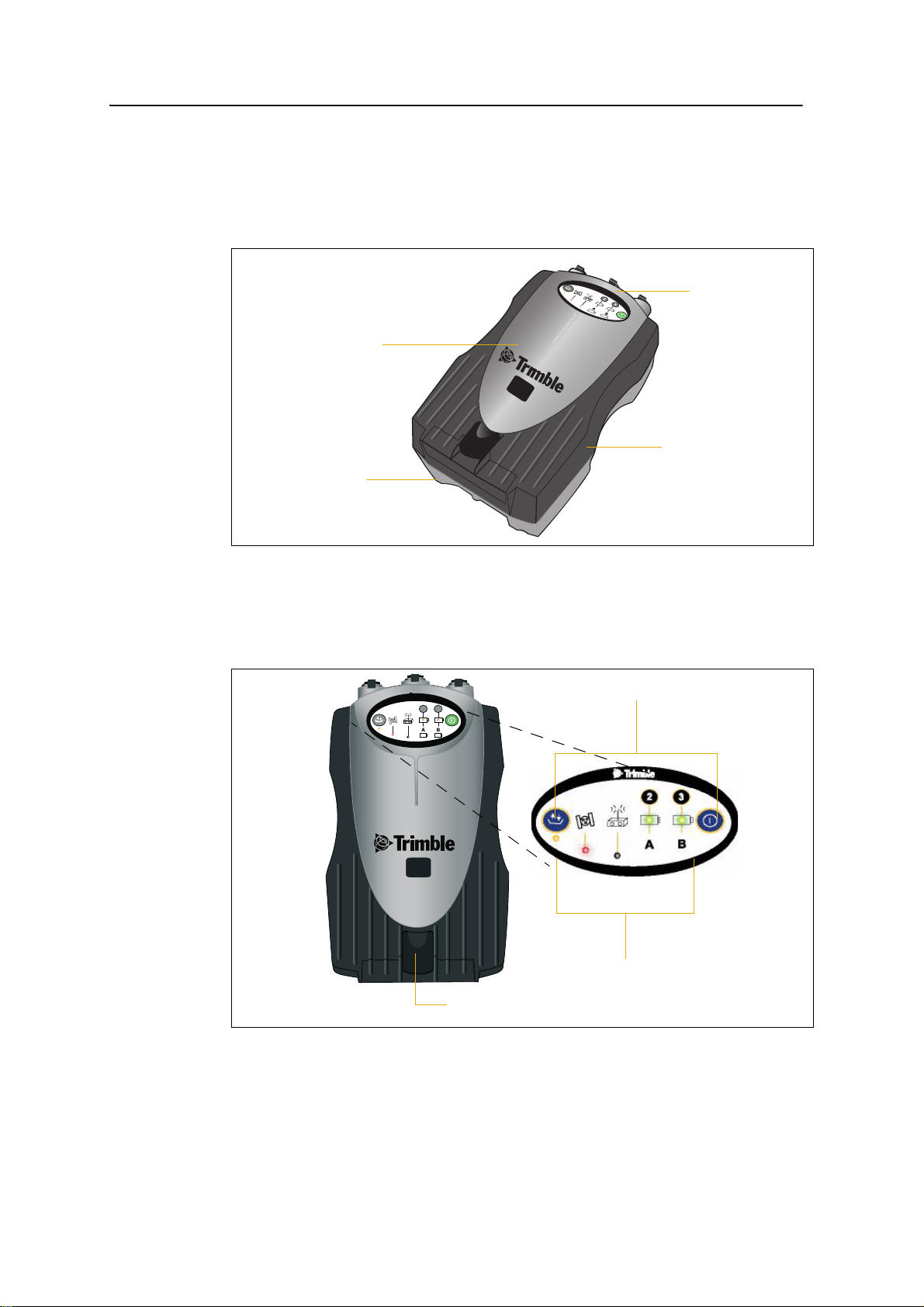
Front panel
Rear
panel
USB door catch
Buttons
Indicator LEDs
CompactFlash/
3.1 Parts of the receiver
All operating controls, ports, and connectors on the receiver are located on its four
main panels, as shown below. This section provides a brief overview of the features of
each of these panels.
31.1 Front panel
The receiver front panel is shown below. This panel contains the indicator LEDs, the
two buttons, and the catch for the CompactFlash/USB door.
R7
GNSS
2
3
The two buttons control data logging, data management, power, and settings. For more
information, see Button functions, page 36.
20 TrimbleR7 GNSS and R5 GPS Receivers User Guide
Page 23
The indicator LEDs show the status of logging, power, satellite tracking, and radio
compartment catches
Receiver
catch lock
Battery
reception. For more information, see LED behavior, page 37.
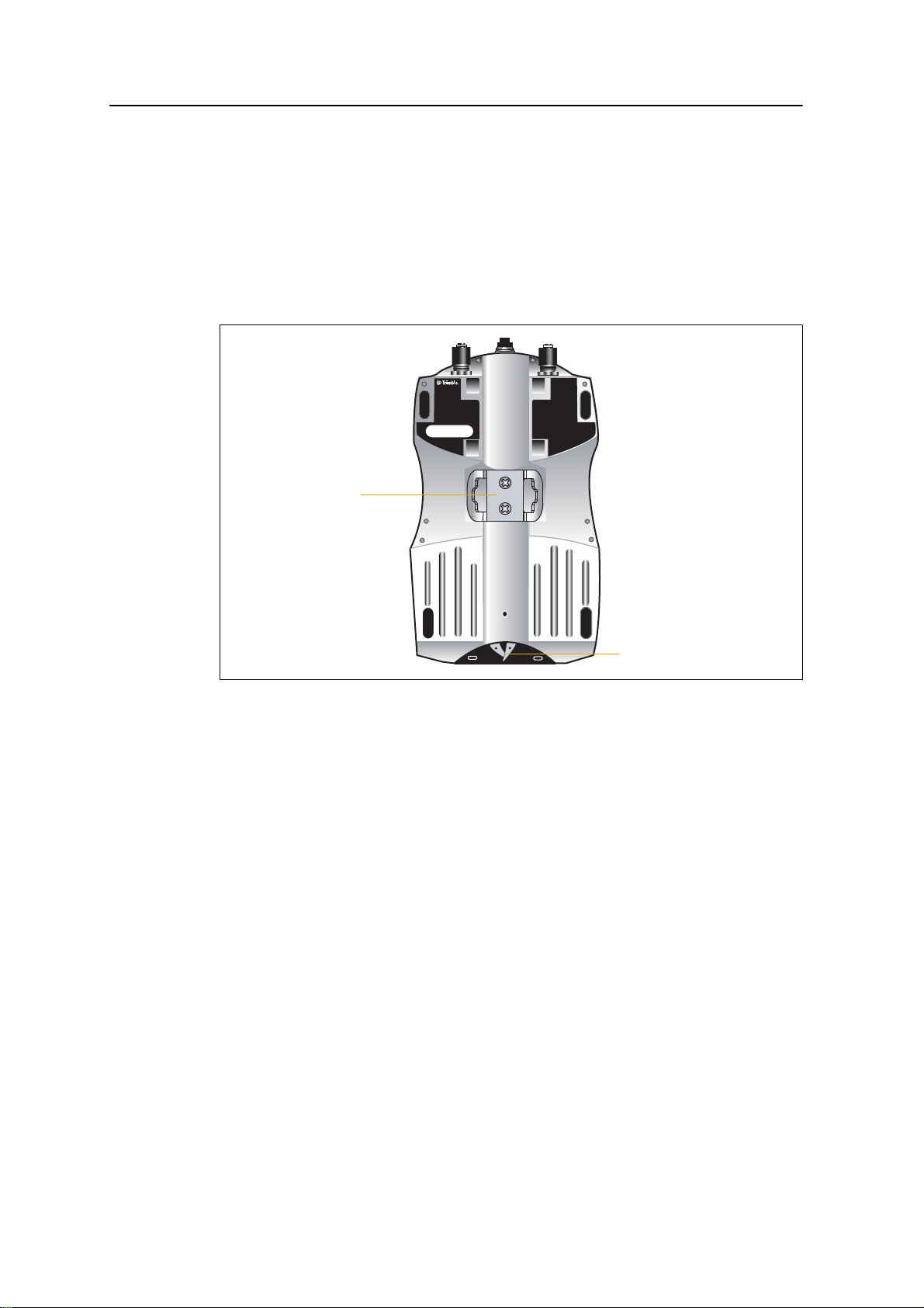
31.2 Rear panel
The receiver rear panel is shown below. This panel contains a slot for attaching the
receiver catch lock, and the catches for the two battery compartments on the bottom
panel. The catch lock should already be attached to your receiver.
Setting up the Receiver 3
To mount the receiver on a pole, attach the receiver bracket to the pole and then insert
the catch lock into the bracket. For more information, see Pole-mounted setup,
page 26.
TrimbleR7 GNSS and R5 GPS Receivers User Guide 21
Page 24
3 Setting up the Receiver
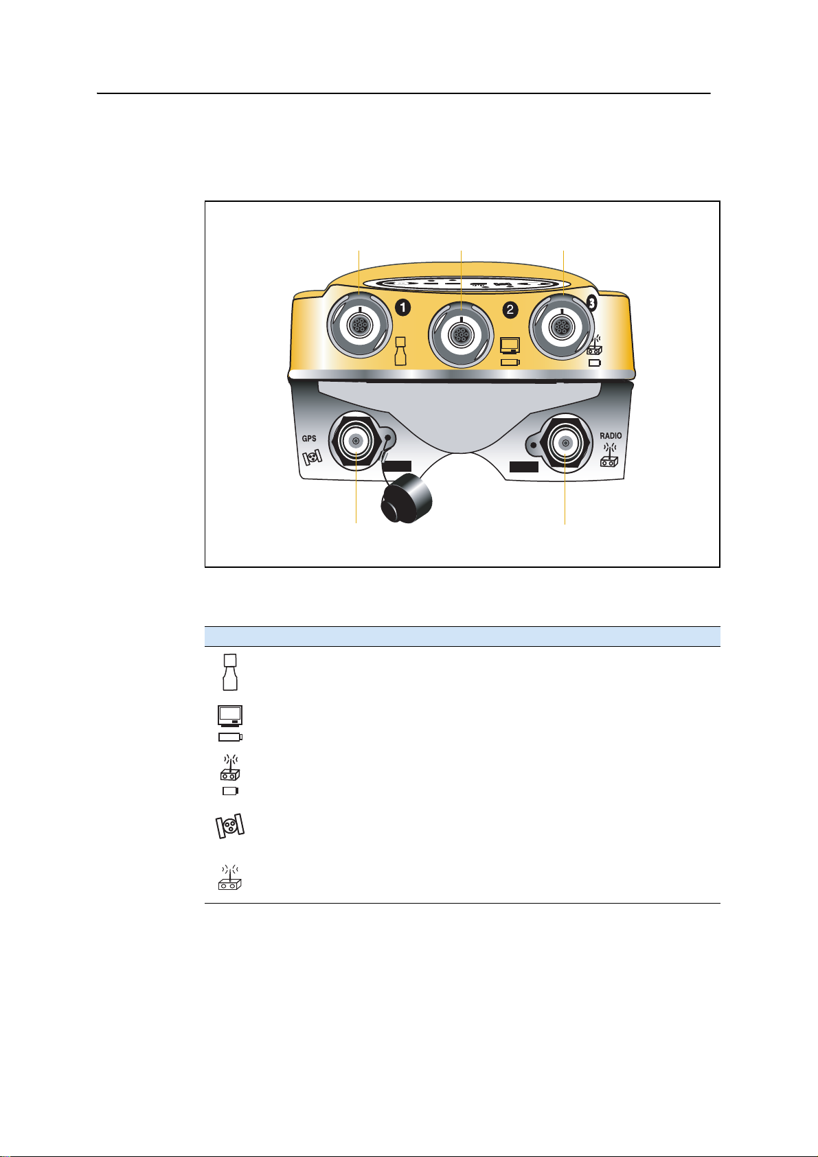
Power/serial data ports
TNC ports
123
GPS/GNSS antenna Radio antenna
31.3 Top panel
The receiver top panel is shown below. This panel contains the three power/serial data
ports and (TNC) ports for GPS and radio antenna connections.
Each port on the top panel is marked with an icon to indicate its main function, as
shown below.
Icon Name Connections
Port 1 Trimble controller, event marker, or computer
Port 2 Power in, computer, 1PPS, or event marker
Port 3 External radio, power in
GPS GPS/GNSS antenna
RADIO Radio communications antenna
The power/serial data ports are all 7 pin 0-shell Lemo connectors. Both Port 2 and
Port 3 can accept external power. For more information, see Default settings, page 62
and Cables and Connectors, page 67.
22 TrimbleR7 GNSS and R5 GPS Receivers User Guide
Page 25

Connect the GPS/GNSS antenna cable to the TNC port marked GPS, and connect the
CompactFlash port
USB port
Internal
compartment
Internal battery
CompactFlash/
USB door
battery
Quarter-wave whip antenna (rubber duck) to the TNC connector marked RADIO. For
more information on connecting the receiver, see the following sections in this chapter.
31.4 Bottom panel
The receiver bottom panel is shown below. This panel contains the USB port, the
CompactFlash port, and the compartments for the two internal batteries.
Setting up the Receiver 3
The CompactFlash/USB door conceals the CompactFlash port and USB port. To open
the door, push down the catch on the front panel.
C
3.2 Setup guidelines
WARNING – When there is no USB cable connected, or when using the receiver in a harsh
environment, keep this door closed to keep moisture, dust, and dirt out of the ports. The
temperature rating of the receiver applies only when all doors on the receiver are closed.
When setting up the receiver, follow these guidelines.
32.1 Environmental conditions
Although the receiver has a waterproof housing, take reasonable care to keep the unit
dry. Avoid exposure to extreme environmental conditions, including:
• Wa ter
• Heat greater than 65° C (149° F)
TrimbleR7 GNSS and R5 GPS Receivers User Guide 23
Page 26

3 Setting up the Receiver
• Cold less than –40° C (–40° F)
• Corrosive fluids and gases
Avoiding these conditions improves the receiver performance and long-term reliability.
32.2 Sources of electrical interference
Avoid the following sources of electrical and magnetic noise:
• Gasoline engines (spark plugs)
• Televisions and computer monitors
• Alternators and generators
• Electric motors
• Equipment with DC-to-AC converters
• Fluorescent lights
• Switching power supplies
32.3 General guidelines
C
WARNING – These receivers use a rechargeable Lithium-ion battery. To avoid personal
injury or equipment damage, make sure that you read and understand the Safety
Information on page 5 at the front of this manual.
The following guidelines apply whenever you set up your receiver for operation:
• When plugging in a Lemo cable, make sure that the red dots on the receiver port
and the cable connector line up. Do not use force to plug cables in, as this may
damage the connector pins.
• When disconnecting a Lemo cable, grasp the cable by the sliding collar or
lanyard and pull the cable connector straight out of the port. Do not twist the
connector or pull on the cable itself.
• To securely connect a TNC cable, align the cable connector with the receiver
receptacle and thread the cable connector onto the receptacle until snug.
• Insert the internal batteries with the battery contacts facing the
CompactFlash/USB door. The undersides of the batteries have a center groove
for alignment when being inserted into the receiver.
3.3 Postprocessed setup
For a postprocessed survey, you only need:
• the receiver
24 TrimbleR7 GNSS and R5 GPS Receivers User Guide
Page 27
Setting up the Receiver 3
2
3
t
2
3
R7
GNSS
• one of the following antennas:
–Zephyr
™
or Zephyr Geodetic
™
– Zephyr 2 or Zephyr Geodetic 2
• a GPS/GNSS antenna cable
Other equipment, as described below, is optional.
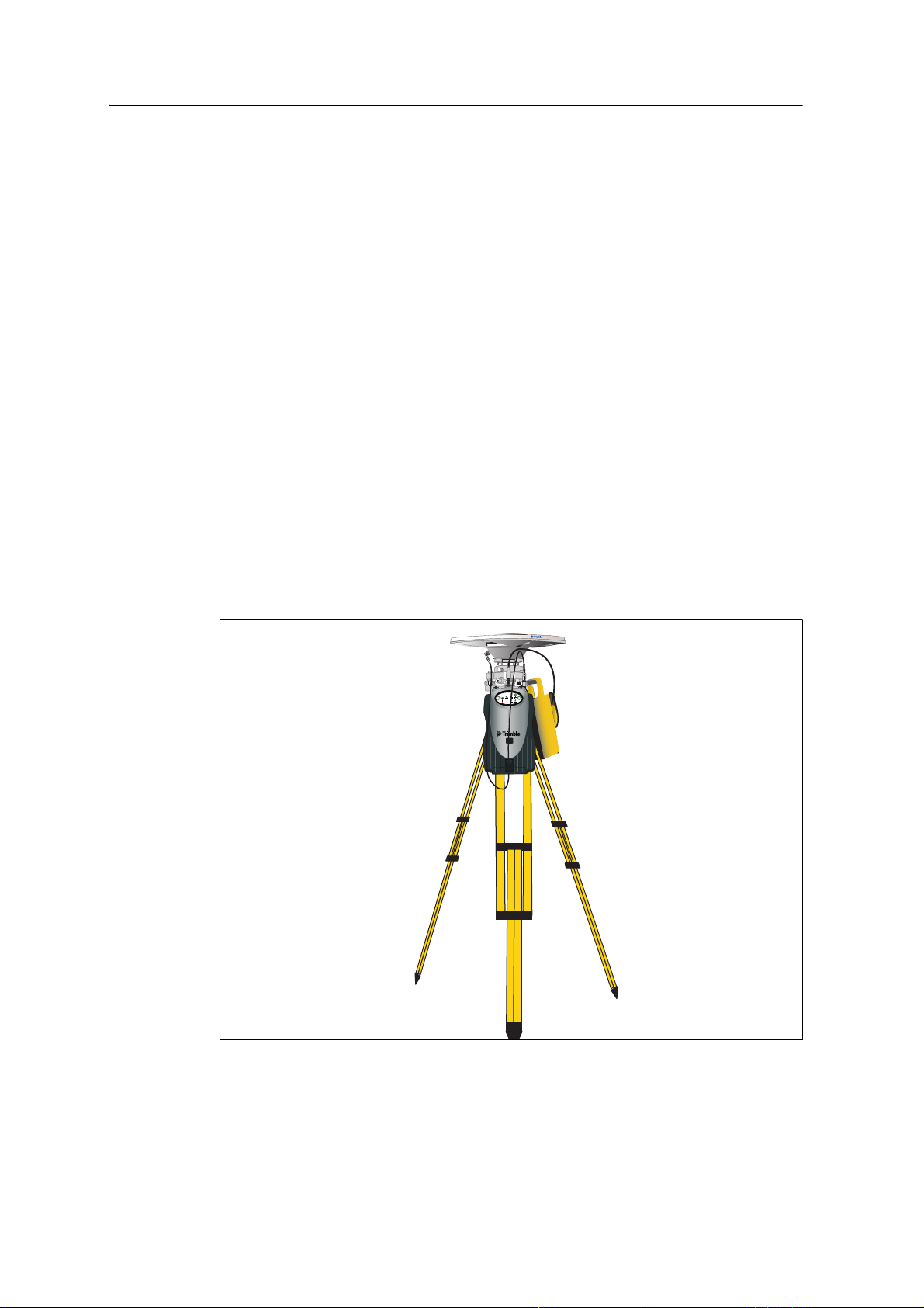
To set up the receiver for a postprocessed survey:
1. Set up the tripod with the tribrach and antenna adapter over the survey mark.
Instead of a tripod, you can use a range pole with a bipod. However, Trimble
recommends that you use a tripod for greater stability.
2. Mount the antenna on the tribrach adapter.
3. Use the tripod clip to hang the receiver on the tripod.
4. Connect the GPS/GNSS antenna cable to the Zephyr antenna.
5. Connect the other end of the GPS/GNSS antenna cable to the TNC port on the
receiver.
6. If external power is required, connect a battery with an 0-shell Lemo connection
to Port 2 or Port 3 on the receiver.
The following figure shows the receiver postprocessed setup.
Note – Instead of hanging the receiver on the tripod, you can place the receiver in its base
case. Run the antenna cable out of the portal in the side of the base case to the antenna so
that the case can stay closed while the receiver is running.
TrimbleR7 GNSS and R5 GPS Receivers User Guide 25
Page 28
3 Setting up the Receiver
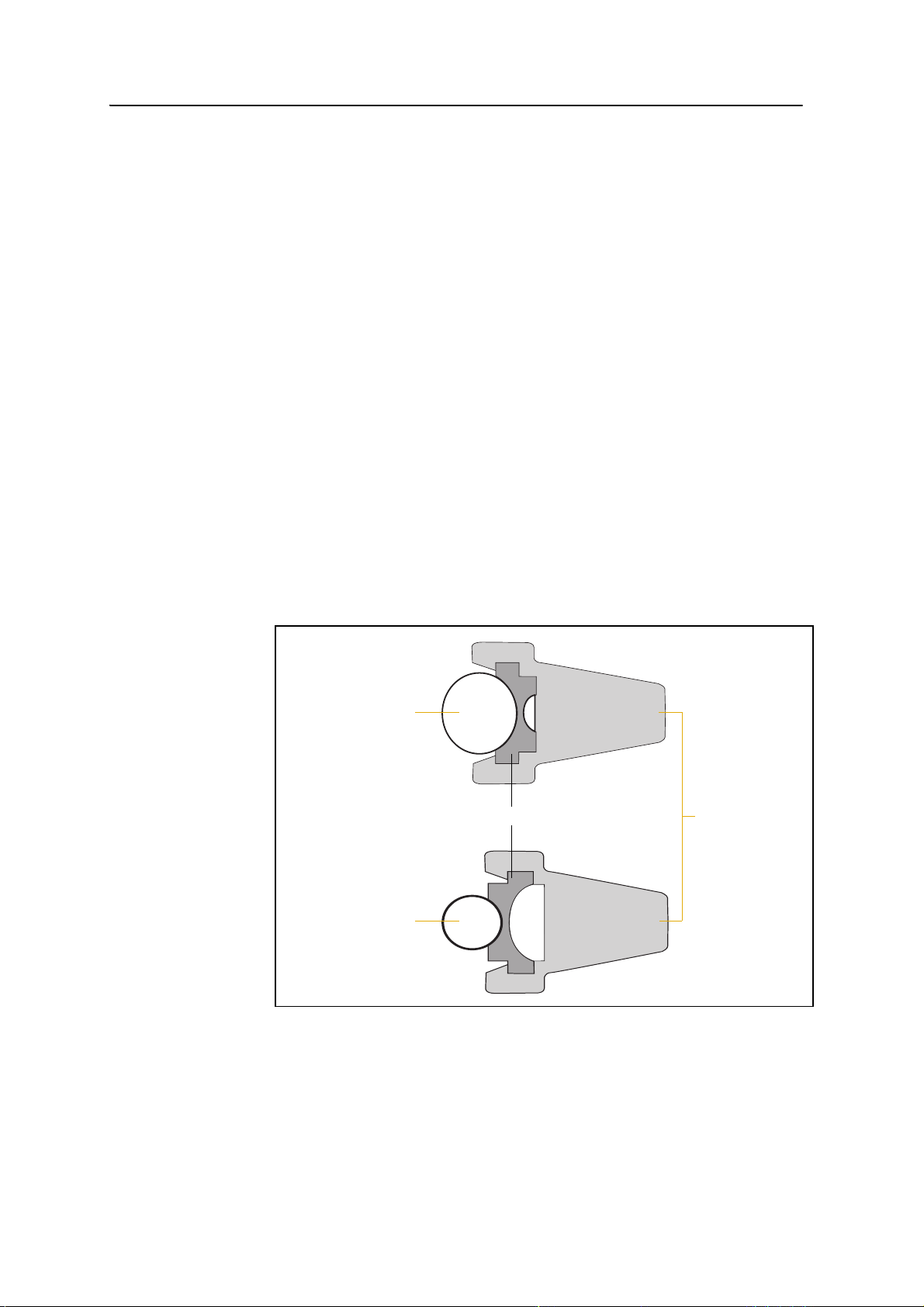
Bracket insert Bracket
1¼" pole
1" pole
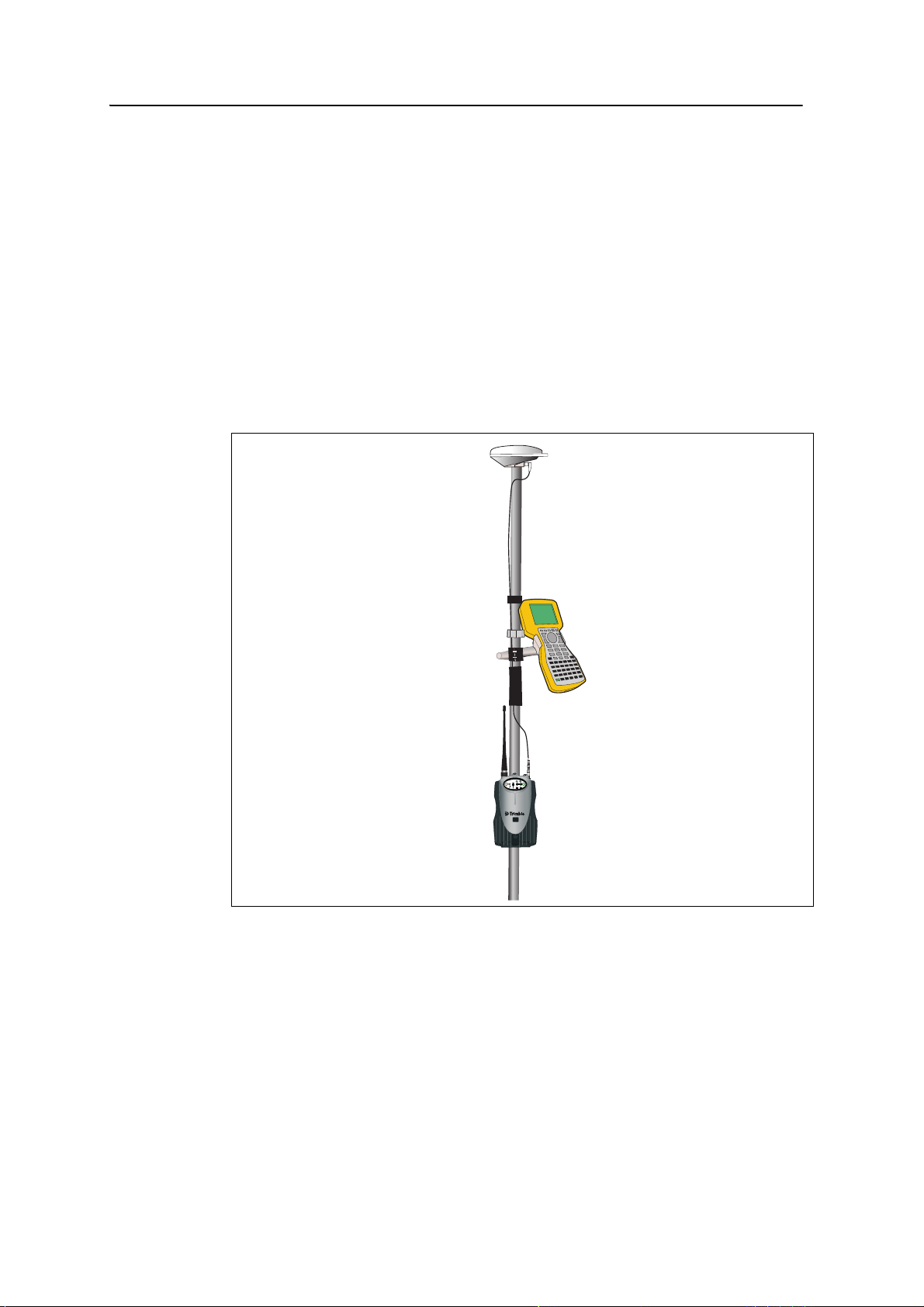
3.1 Pole-mounted setup
Do the following:
1. Mount the Zephyr antenna. See page 26.
2. Mount the receiver on the pole. See page 26.
3. Attach the controller. See page 27.
30.1 Mounting the Zephyr antenna
1. Screw the antenna to the 5/8-11 threads on the top of the range pole.
2. Connect the TNC-to-TNC GPS cable to the port on the top of the receiver.
3. Connect the TNC-to-TNC GPS cable to the antenna.
30.1 Mounting the receiver on the pole
1. Attach the receiver bracket to the pole:
a. Place the bracket against the pole, approximately 0.5 m from the ground.
Note – If you are using a 1" diameter pole, flip the bracket insert around inside the bracket,
as shown in Figure 3.1.
Figure 3.1 Receiver bracket insert
b. Close the gates of the bracket around the pole.
c. Seat the base of the clip lock in the opposite gate.
26 TrimbleR7 GNSS and R5 GPS Receivers User Guide
Page 29

Setting up the Receiver 3
Clip lock
Gates
Side locks
d. Lock the clip lock.
If the clip lock is too tight to be locked, turn it one or two turns
counterclockwise and try again. If it is too loose, turn it one or two turns
clockwise and try to lock it again.
2. Mount the receiver on the bracket:
a. Pull the bracket side locks in towards the pole.
b. Set the receiver catch lock in the bracket.
c. Holding the receiver in the bracket, pull the side locks back to their original
positions, as shown below.
3. Connect the quarter-wave whip (“rubber duck”) antenna to the radio port on
top of the receiver.
4. If necessary, adjust the position of the receiver to remove cable slack from the
TNC GPS antenna cable.
30.1 Mounting the controller
1. Mount the TSC2
a. Place the bracket against the pole at a comfortable height.
b. Rotate the pole clamping screw on the controller bracket until tight.
c. Place the controller into the cradle assembly and tighten the clamping
mechanism.
d. If there are any cables running down the pole, run them through the
machined groove on the inside of the controller bracket.
e. To put the controller in the preferred position for operation, press the
spring-loaded release button on the cradle, pull the assembly outward, and
then rotate the cradle assembly to the required angle. To rest the cradle in
®
controller bracket on the pole:
TrimbleR7 GNSS and R5 GPS Receivers User Guide 27
Page 30
3 Setting up the Receiver
Note – If you use Bluetooth
steps 2 and 3.
2. Connect the DB9-to-0-shell Lemo cable to the controller.
3. Connect the other end of the cable to Lemo Port 1 on the receiver.
4. Place the hand grip below the controller bracket (or above it, depending on the
5. Secure any loose cables, using the velcro cable ties.
The following figure shows the completed pole-mounted setup.
the proper position, line up the alignment pin on the cradle with the hole in
the controller bracket and then push it inward until the release button
locks.
wireless technology with the Trimble R7 GNSS receiver, omit
position of the bracket), with the cables running through the grip.
3.1 Backpack setup
To set up the receiver for use in a backpack:
1. Insert the receiver into the backpack with the ports on the top panel facing
upwards and the front panel facing outwards. Secure the receiver around the
middle with the velcro strap.
2. Attach the Zephyr
28 TrimbleR7 GNSS and R5 GPS Receivers User Guide
™
2
3
R7
GNSS
antenna to a range pole.
Page 31

Setting up the Receiver 3
3. Attach the whip antenna mount to one of the fittings on the top of the backpack.
4. The backpack has a feedthrough on both sides at the top and on both sides near
the bottom to allow cables to be positioned out of the way of the main zipper.
Run the radio communications cable through at the top, and connect it to the
blue TNC port on the receiver.
5. Connect the straight end of the yellow GPS cable to the yellow TNC port on the
receiver.
6. Run the right-angle connector on the yellow GPS cable through the top or side
slot on the backpack, and then connect it to the Zephyr antenna.
7. Connect the DB9-to-0-shell Lemo cable to Port 1 on the receiver.
8. Run the DB9 cable through the side slot of the backpack and then connect it to
the controller.
Note – Trimble does not recommend using a Bluetooth connection for a backpack setup.
TrimbleR7 GNSS and R5 GPS Receivers User Guide 29
Page 32

3 Setting up the Receiver
Whip antenna
Zephyr antenna
Controller bracket
The following figure shows the backpack setup.
2
3
R7
GNSS
3.1 Other system components
This section describes optional components that you can use with the receiver.
31.1 Radios
Radios are the most common data link for Real-Time Kinematic (RTK) surveying. The
receiver is available with an internal receive-only radio that uses a UHF frequency band
in the 410 MHz to 470 MHz range. You can also connect an external radio to Port 3,
whether or not the internal radio is installed.
The receiver supports the following Trimble base radios when using the internal
receiver radio:
• Trimble HPB450
• Trimble PDL450
30 TrimbleR7 GNSS and R5 GPS Receivers User Guide
• Trimble TDL 450L
• Receiver internal 450 MHz transmitter
Page 33

Setting up the Receiver 3
• TRIMMARK
• SiteNet
™
™
450 radio
3 radio
Internal radio setup
To configure the receiver optional internal radio, use one of the following:
• The GPS Configurator software
• The WinFlash utility
• The Trimble Survey Controller
• The Trimble Digital Fieldbook
™
software
™
software
For more information, refer to the documentation for these applications.
By default, the internal radio has only a few “test” frequencies installed at the factory.
You can program the receive frequencies using the WinFlash utility. For more
information, see The WinFlash utility, page 98.
External radio setup
To use an external radio with the receiver, you need to set up an external power source
for the radio:
1. Connect one end of the GPS antenna cable to the TNC port on the receiver.
2. Connect the other end of the GPS antenna cable to one of the following
antennas:
– Zephyr or Zephyr Geodetic
– Zephyr 2 or Zephyr Geodetic 2
3. Connect the external radio to Port 3 on the receiver.
4. Connect a radio antenna to the external radio.
5. Connect an external power source to Port 2 on the receiver.
Note – External rover radios must have their own power source because the
internal Lithium-ion batteries do not supply enough voltage. Alternatively, supply
external power to Port 2 of the receiver, and enable power out on Port 3.
Base (transmit/receive) radios must have their own power source because of their
high power consumption.
Alternatively, you can apply external power directly to the radio, if it supports it.
You can use a 10 Ah battery, a 6 Ah battery, or camcorder batteries. The choice
of power supply depends on the application, and whether you are using the
radio as a base or rover radio. For more information about the power capabilities
of the receiver, see Batteries and power, page 40.
TrimbleR7 GNSS and R5 GPS Receivers User Guide 31
Page 34

3 Setting up the Receiver
6. Configure the external radio using Trimble Survey Controller software.
Alternatively, you can configure an external radio using the WinFlash utility or
the configuration software supplied with the radio.
For more information, refer to the Trimble Survey Controller User Guide or the
appropriate Help.
7. Set up any other equipment as required, depending on whether you are using
the radio as a reference or a rover radio.
30.1 Cellular modems
You can use a cellular modem instead of a radio as your data communications link.
Cellular modems and other radio links can be used to extend the limits of your surveys.
To connect a cellular modem to a receiver, you need the following:
• A receiver
• A custom-designed cellular modem, or a cellphone that can transmit and
receive data
• Serial (cellphone to DB9) cable (supplied with the cellular modem or phone)
• Trimble DB9 to 0-shell Lemo cable
Note – This cable is suitable only if flow control can be disabled on the cellular modem. If
the cellular modem does not support this functionality, a special cable is required. For
more information, refer to the document Using Cellular and CDPD Modems for RTK,
which is available from your local Trimble Reseller.
The following figure shows the components required to connect a cellphone to a
receiver.
32 TrimbleR7 GNSS and R5 GPS Receivers User Guide
Page 35

R7
Serial cable
DB9 to Lemo cable
GNSS
Setting up the Receiver 3
2
3
PUSH
For more information on using a cellular modem as a data link, refer to the Trimble
Survey Controller User Guide.
30.2 Antennas
The receiver should normally be used with one of the following antennas, which have
been designed specifically for them:
• Zephyr or Zephyr Geodetic
• Zephyr 2 or Zephyr Geodetic 2
Use the following figure as a guide for measuring the height of the Zephyr and Zephyr
Geodetic antennas. The Zephyr antenna is designed to be measured to the top of the
notch. The Zephyr Geodetic (shown) has been designed to be measured to the bottom
of the notch.
TrimbleR7 GNSS and R5 GPS Receivers User Guide 33
Page 36

3 Setting up the Receiver
Some models of antennas, such as the Choke Ring or older Micro-Centered™ L1/L2
antennas, need more power to operate than the Zephyr models. To configure the
receiver to output more power on the antenna port, select the correct antenna type in
GPS Configurator, or through the Trimble controller. For information on how to do
this, contact your local Trimble Service Provider.
1.520
1.515
1.510
1.505
30.3 CompactFlash cards
The receiver logs data internally on a CompactFlash card. However, it only support the
Type I CompactFlash card. Trimble recommends that you use an industrial-rated
CompactFlash card, as commercial cards have a limited operating temperature range.
Before logging data to a CompactFlash card, format the card to ensure the integrity of
the file system. To format the card, insert it in the receiver and then hold down the
power button for 30 seconds.
Note – Make sure that you format your CompactFlash card in the receiver. This prevents
data on the card from being corrupted if the card is removed while data is being logged.
Formatting the card in your computer may cause data corruption, or loss of data.
When inserting the card, make sure that it slides into the card slot properly.
C
C
CAUTION – The receiver allows for more than 500 files on the CompactFlash card,
regardless of the card’s capacity. The file names must be in 8.3 format, otherwise, files
copied to the CompactFlash card may cause data corruption or loss of data when logging.
CAUTION – If the card does not seat into the pins correctly, do not use force or you may
damage the pins. Remove the card and carefully reinsert it.
34 TrimbleR7 GNSS and R5 GPS Receivers User Guide
Page 37

CHAPTER
4
General Operation 4
In this chapter:
Front panel controls
Button functions
LED behavior
Starting and stopping the receiver
Logging data
Resetting to defaults
Formatting a CompactFlash card
Batteries and power
All the controls that you need for general receiver
operation are on the front panel.
For more information about other receiver
panels, see Parts of the receiver, page 20.
TrimbleR7 GNSS and R5 GPS Receivers User Guide 35
Page 38

4 General Operation
Logging/
Memory LED
Data button
Power button
Battery LEDs
SV Tracking
Radio/Event
LED
Marker LED
4.1 Front panel controls
Figure 4.1 Receiver front panel controls and LEDs
4.2 Button functions
The receiver has only two buttons: the Power button and the Data button
Press to switch the receiver on or off, and to perform data management functions
such as deleting files or resetting the receiver.
to start or stop logging. This button is effective only when the receiver is
Press
switched on and has completed any power-up and initialization tasks.
Ta bl e 4 . 1 describes the main functions of the two buttons.
Table 4.1 Button functions
Action Power button Data button
Turn on the receiver Press
Turn off the receiver Hold for 2 seconds
Start logging data internally Press
Stop logging data internally Hold for 2 seconds
Delete the ephemeris file Hold for 15 seconds
Reset the receiver to factory defaults Hold for 15 seconds
Delete application files Hold for 30 seconds
Format the CompactFlash card Hold for 30 seconds
Note – The term “press” means to press the button and release it immediately. The term
“hold” means to press the button and hold it down for the given time.
36 TrimbleR7 GNSS and R5 GPS Receivers User Guide
Page 39

4.3 LED behavior
The five LEDs on the top panel of the receiver indicate various operating conditions.
Generally, a lit or slowly flashing LED indicates normal operation, an LED that is
flashing quickly indicates a condition that may require attention, and an unlit LED
indicates that no operation is occurring. The following table defines each possible LED
state.
The term … means that the LED …
Flash is lit briefly every 3 seconds
Slow flash alternates slowly between being lit and unlit
Fast flash alternates rapidly between being lit and unlit
On is lit
Off is unlit
43.1 Logging/memory LED
The yellow Logging/memory LED below the button indicates the status of data
logging and memory usage.
General Operation 4
Behavior Meaning
On Data is being logged.
Slow flash Enough FastStatic data has been logged.
Fast flash Data is being logged but memory is low.
Very slow flash The receiver is in Sleep mode, and will wake up five minutes before the
Off Data is not being logged.
43.2 SV Tracking LED
The red SV Tracking LED below the SV icon indicates the status of satellite
tracking.
Behavior Meaning
Slow flash Tracking four or more satellites.
Fast flash Tracking three or fewer satellites.
Off Not tracking any satellites.
On The receiver is in Monitor mode, and is checking for new firmware to
Alternatively, if the red SV Tracking LED is on solid at the same time and the
other LEDs are off, the receiver is in Monitor mode. Turn off the power and
then turn it on again to return to normal operation.
scheduled start time of a timed application file.
install.
TrimbleR7 GNSS and R5 GPS Receivers User Guide 37
Page 40

4 General Operation
43.3 Radio LED
The green Radio LED below the Radio icon indicates the status of data input and
output.
Behavior Meaning
Slow flash A data packet or event marker has been received.
43.4 Battery 1 LED and battery 2 LED
The Battery LEDs inside the two Battery icons indicate the status of the two
internal batteries, or the power sources connected on Ports 2 and 3.
By default, each battery LED indicates the status of the external power source on the
corresponding port. If no external source is detected, each LED indicates the status of
an internal battery. The color of the LED indicates whether the power source is
currently in use (green) or is on standby (yellow).
Color Meaning Behavior Meaning
Green Power source is
in use
Yellow Power source is
on standby
On Healthy
Fast flash Low power
Off No power source is present
On Healthy
Fast flash Low power
Flash Dead
Off No power source is present
4.4 Starting and stopping the receiver
To turn on the receiver, press .
To turn off the receiver, hold down
. The SV LED turns on, and then turns off after two
seconds. When the LED turns off, release
4.5 Logging data
You can log data to the CompactFlash card in the receiver, or to a Trimble controller.
45.1 Logging internally
The receiver logs GPS data internally on a CompactFlash card. Use Trimble Business
Center to download the T01 formatted files directly from the CompactFlash card to
the office computer. Alternatively, you can use the Trimble Data Transfer utility to
transfer logged data files to your office computer. The transferred files are in Trimble
DAT (.dat) format.
38 TrimbleR7 GNSS and R5 GPS Receivers User Guide
; the receiver turns off.
Page 41

General Operation 4
If you use the Data Transfer utility to download the internally-logged files, a DAT (.dat)
file is automatically created after the download; DAT files do not contain GLONASS
™
data. These files are appropriate for processing in Trimble Geomatics Office
software
because that software does not process GLONASS data.
If you have the Trimble Business Center software, the T01 file that is stored on the
receiver can be directly downloaded; these files contain any collected GLONASS data.
The Trimble Business Center software can process GLONASS data, if you have
purchased that option.
CAUTION – The receiver allows for more than 500 files on the CompactFlash card,
regardless of the card’s capacity. The file names must be in 8.3 format, otherwise, files
copied to the CompactFlash card may cause data corruption or loss of data when logging.
Data is logged using the current logging settings configured in the receiver. Data files
logged internally are named automatically.
To begin internal logging, press
To stop logging, hold down
for at least two seconds. The Logging/memory LED
turns off.
Note – When the CompactFlash card is full, if auto-delete is not enabled, the receiver stops
logging data, and the Logging/memory LED turns off. Existing data files are not
overwritten.
Approximate storage requirements for different logging rates are shown below. The
values shown are for a one-hour logging session with six satellites visible.
Logging rate Minimum memory required
10 Hz 2,588 KB
1 Hz 335 KB
5 seconds 87 KB
15 seconds 37 KB
Note – If power is lost, or the CompactFlash card is removed while logging, the file system
is designed so that a maximum of ten seconds of data will be lost, regardless of the logging
rate.
45.2 Logging to a Trimble controller
. The Logging/memory LED lights up.
When the receiver is connected to a Trimble controller, you can log GPS data from the
receiver to the controller, or to a data card inserted in the controller. When you use a
Trimble controller, you do not use the receiver’s controls. Instead, you use the
controller functions to set logging options, specify filenames, and to control when
logging occurs.
Controller software job files and the corresponding raw data files can be transferred to
an office computer using the Trimble Data Transfer utility.
TrimbleR7 GNSS and R5 GPS Receivers User Guide 39
Page 42

4 General Operation
For more information on logging data from a receiver using a Trimble controller, refer
to the user guide for your particular controller.
4.6 Resetting to defaults
C
CAUTION – If you hold down for more than 30 seconds, any application files stored in
the receiver are deleted and the CompactFlash card is reformatted.
To reset the receiver to its factory default settings, hold down for at least 15 seconds.
Resetting the receiver to its factory defaults also deletes any ephemeris file in the
receiver.
For more information, see Chapter 8, Default Settings.
4.7 Formatting a CompactFlash card
C
CAUTION – Formatting a CompactFlash card while it is in the receiver deletes all the data
files on the card.
To format a CompactFlash card for use in the receiver, insert the card in the
CompactFlash port and then hold down
the receiver is reset to its factory defaults, and any ephemeris file is deleted. After 30
seconds, any files stored on the card are deleted and the CompactFlash card is
reformatted.
Note – When you use
to format the CompactFlash card, a quick format is performed. A
quick format reformats the card for use with the receiver and deletes all data on the card.
A full format checks the card for errors or bad sectors, and is only necessary if the card is
corrupted. To perform a full format, use the GPS Configurator software. For more
information, see The GPS Configurator software, page 98.
for at least 30 seconds. After 15 seconds,
4.8 Batteries and power
C
40 TrimbleR7 GNSS and R5 GPS Receivers User Guide
WARNING – Do not damage the rechargeable Lithium-ion battery. A damaged battery
can cause an explosion or fire, and can result in personal injury and/or property damage.
To prevent injury or damage:
– Do not use or charge the battery if it appears to be damaged. Signs of damage include,
but are not limited to, discoloration, warping, and leaking battery fluid.
– Do not expose the battery to fire, high temperature, or direct sunlight.
– Do not immerse the battery in water.
– Do not use or store the battery inside a vehicle during hot weather.
– Do not drop or puncture the battery.
– Do not open the battery or short-circuit its contacts.
Page 43

General Operation 4
The receiver can be powered either by its two internal batteries or by an external
power source connected to Port 2 or Port 3. The charge provided by the internal
batteries depends on the type of survey and operating conditions.
The external power source is always used in preference to the internal batteries. When
there is no external power source connected, or if the external power supply fails, the
internal batteries are used. The internal batteries are drained in turn, and the receiver
automatically switches to the full battery when the first battery is drained.
If no external power is supplied and both internal batteries are drained, none of the
data that you have logged is lost. When internal or external power is restored, the
receiver restarts in the same state as when power was lost. For example, if the receiver
was logging data, the data file is not corrupted, and when power is restored the
receiver resumes logging with the same settings as before.
The power supply that comes with the receiver charges the internal batteries while
they are still in the receiver. To do this, connect the power supply to the power/serial
data cable, connect the cable to Port 2 on the receiver and then connect the power
supply to an AC power source, as shown below.
TrimbleR7 GNSS and R5 GPS Receivers User Guide 41
Page 44

4 General Operation
Power/serial data cable
To A C
power supply
R7
GNSS
2
3
The two internal batteries take approximately eight hours to charge. They are charged
individually, so each battery takes approximately four hours to charge. The internal
batteries start charging whenever an external power supply of greater than 15 V is
detected.
42 TrimbleR7 GNSS and R5 GPS Receivers User Guide
Page 45

General Operation 4
C
WARNING – Avoid contact with the rechargeable Lithium-ion battery if it appears to be
leaking. Battery fluid is corrosive, and contact with it can result in personal injury and/or
property damage.
To prevent injury or damage:
– If the battery leaks, avoid contact with the battery fluid.
– If battery fluid gets into your eyes, immediately rinse your eyes with clean water and
seek medical attention. Do not rub your eyes!
– If battery fluid gets onto your skin or clothing, immediately use clean water to wash off
the battery fluid.
Each receiver in your system is supplied with two internal Lithium-ion batteries. To
charge both sets of batteries, connect both receivers to power supplies as shown in
Figure 4.2.
48.1 Battery charging and storage
All battery types discharge over time when they are not being used. Batteries also
discharge faster in colder temperatures. If a Lithium-ion battery is to be stored for long
periods of time, make sure it is fully charged before storing and re-charged at least
every three months.
C
WARNING – Charge and use the rechargeable Lithium-ion battery only in strict
accordance with the instructions. Charging or using the battery in unauthorized
equipment can cause an explosion or fire, and can result in personal injury and/or
equipment damage.
To prevent injury or damage:
– Do not charge or use the battery if it appears to be damaged or leaking.
– Charge the Lithium-ion battery only in a Trimble product that is specified to charge it.
Be sure to follow all instructions that are provided with the battery charger.
– Discontinue charging a battery that gives off extreme heat or a burning odor.
– Use the battery only in Trimble equipment that is specified to use it.
– Use the battery only for its intended use and according to the instructions in the product
documentation.
Charging the Lithium-ion battery
The rechargeable Lithium-ion battery is supplied partially charged. Charge the battery
completely before using it for the first time. If the battery has been stored for longer
than six months, charge it before use.
To protect the battery from deep discharge (5 V or less), the receiver is designed to
switch batteries or cease drawing power when the battery pack discharges to 5.9 V.
A battery that has reached the deep discharge level cannot be recharged and must be
replaced. The following recommendations provide optimal performance and extend
the life of your batteries:
• Fully charge all new batteries before use.
• Do not allow the batteries to discharge below 5 volts.
TrimbleR7 GNSS and R5 GPS Receivers User Guide 43
Page 46

4 General Operation
• Keep all batteries on continuous charge when not in use. Batteries may be kept
on charge indefinitely without damage to the receiver or batteries.
• Do not store batteries in the receiver or external charger unless power is applied.
• If you must store the batteries, fully charge them before storing and then
recharge them at least every three months.
Disposing of the rechargeable Lithium-ion battery
Discharge the Lithium-ion battery before disposing of it. When disposing of the
battery, be sure to do so in an environmentally sensitive manner. Adhere to any local
and national regulations concerning battery disposal or recycling.
48.2 Operating with the controller
If the receiver is being powered by its internal batteries, it does not supply power to the
controller when they are connected. The receiver and the Trimble controller must be
charged using their own power supplies with connections to the AC power supply from
the wall.
48.3 Power output
If the receiver is being supplied with power from an external source, power is
automatically output on Port 1. Port 1 outputs a maximum voltage of 20 V, even if the
input voltage is higher.
You can use GPS Configurator or Trimble Survey Controller software to enable power
output on Port 3. Port 3 can be enabled for power output regardless of whether power
is supplied internally or externally.
On Port 3, the output voltage is approximately 0.5 V less than the input voltage. For
example, if power is being supplied from the internal Lithium-ion batteries, the
maximum battery voltage is 8.4 V, so the maximum output voltage is 7.9 V.
Note – When you start a survey using the Trimble Survey Controller software, and you are
using an external radio, the software automatically enables power output on Port 3.
48.4 Firmware
A receiver’s firmware is the program inside the receiver that makes the receiver run and
controls the hardware. You can upgrade the firmware for the receiver using the
WinFlash utility provided on the receiver CD. For more information, see The WinFlash
utility, page 98.
C
44 TrimbleR7 GNSS and R5 GPS Receivers User Guide
CAUTION – Downgrading the firmware deletes all application files on the receiver.
Page 47

CHAPTER
5
Configuration 5
In this chapter:
Configuring the receiver in real
Time
Configuring the receiver using
application files
Application files
The receiver has no controls to change settings.
To configure the receiver, use external software,
such as GPS Configurator, WinFlash, Trimble
Survey Controller, or Trimble Digital Fieldbook.
To configure the receiver, do one of the following:
• Configure the receiver in real time
• Apply the settings in an application file
This chapter provides a brief overview of each of
these methods, and describes the contents and
use of application files.
TrimbleR7 GNSS and R5 GPS Receivers User Guide 45
Page 48

5 Configuration
5.1 Configuring the receiver in real Time
The GPS Configurator, Trimble Survey Controller, and Trimble Digital Fieldbook
software support real-time configuration of the receiver.
When you configure the receiver in real time, you use one of these software
applications to specify which settings you want to change. When you apply the
changes, the receiver settings change immediately.
Any changes that you apply to the receiver are reflected in the current application file,
which is always present in the receiver. The current application file always records the
most recent configuration, so if you apply further changes (either in real time or using
an application file) the current file is updated and there is no record of the changes that
you applied originally.
For more information on configuring the receiver in real time, see Chapter D, Software
Utilities.
5.2 Configuring the receiver using application files
An application file contains information for configuring a receiver. To configure a
receiver using an application file, you need to create the application file, transfer it to
the receiver, and then apply the file settings. The GPS Configurator software does this
for you automatically when you work with configuration files.
For more information on applying application files, see Chapter D, Software Utilities.
5.3 Application files
Application files store a receiver’s configuration for use at a later time.
You can store up to ten different application files in battery-backed memory on the
receiver. You can apply an application file’s settings at the time it is transferred to the
receiver, or at any time afterwards.
53.1 Special application files
The receiver has three special application files, which control important aspects of the
receiver’s configuration.
Default application file
The default application file (Default.cfg) contains the original receiver configuration,
and cannot be changed. This file configures the receiver after it is reset. To reset the
receiver, hold down the Power button for at least 15 seconds, or use the reset option in
the GPS Configurator software.
For more information, see Default settings, page 62.
46 TrimbleR7 GNSS and R5 GPS Receivers User Guide
Page 49

Configuration 5
Although you cannot change or delete the default application file, you can use a power
up application file to override any or all of the default settings.
Current application file
The current application file (Current.cfg) reflects the current receiver configuration.
Whenever you change the receiver’s configuration, either in real time or by applying an
application file, the current file changes to match the new configuration.
You cannot delete the current file or change it directly, but every change to the
receiver’s current configuration is applied to the current file as well.
When you turn off the receiver then turn it on again, all the settings from the current
application file are applied, so you do not lose any changes that you have made. The
only exceptions are the following logging parameters:
• Logging rate
• Position rate
• Elevation mask
These parameters are always reset to the factory default values whenever the receiver
is switched off.
Power up application file
The power up application file (Power_up.cfg) is optional. if a power up file is present,
its settings are applied whenever the receiver is turned on.
In this file, you can specify that the receiver is reset to defaults before the power up
settings are applied. This ensures that restarting the receiver always results in the same
configuration. This method is useful for defining “default” settings for the receiver that
differ from those in the default file, which cannot be changed.
Alternatively, you can specify that the power up settings are applied immediately after
the current application file’s settings have been applied. Restarting the receiver results
in a configuration that uses your default settings for the options you define in the
power up file, but the current settings for all other options.
By default, there is no power_up application file on the receiver. To use a power up
application file, you must create and save a power_up application file in the GPS
Configurator software. If you save this file to disk, the file is called power_up.cfg. The
extension .cfg is used by convention to identify application files on the office computer.
when you transfer this file to the receiver, the file is saved on the receiver as power_up,
and becomes the new power up file.
53.2 Timed application files
A timed application file contains a Timed Activation record which specifies when this
file is to be applied. The main use of a timed application file is to automatically start or
stop logging at a predefined time.
TrimbleR7 GNSS and R5 GPS Receivers User Guide 47
Page 50

5 Configuration
The Timed Activation record specifies:
• the UTC date and time when the application file is to be applied for the first
time
• the interval at which the file is to be reapplied
If you do not specify a repeat interval, the settings are applied only once, at the
specified time. If the file specifies a repeat interval, the file’s settings are reapplied at the
specified interval until the file is deactivated.
Note – If the receiver is logging continuously, the current logging takes precedence over any
timed application file stored in the receiver.
Defining timed application files
To send timed application files to a receiver, set up scheduled survey sessions in the
GPS Configurator software. You can define multiple sessions, each specifying:
• basic logging parameters (data logging rate, position logging rate, and elevation
mask)
• a starting time
• a duration
When you apply the current settings in the GPS Configurator software, each defined
survey session is sent to the receiver as a pair of timed application files: the first
includes the logging settings and start time, and the second contains settings that stop
logging at the end time (which is calculated automatically from the duration you
specify).
For more information on scheduled survey sessions, refer to the GPS Configurator
Help.
The receiver can store up to 10 application files, so you can define a maximum of 5
scheduled survey sessions (5 pairs of start/stop timed application files).
Sleep mode
Whenever you press
[P] to turn off the receiver, the receiver checks for a timed
application file that is due to be activated in the future. If one exists, the receiver goes
into Sleep mode instead of turning off.
In Sleep mode, the yellow Logging/memory LED flashes every three seconds. The
receiver wakes up five minutes before the scheduled activation time, so that it is ready
to begin logging at the scheduled time.
48 TrimbleR7 GNSS and R5 GPS Receivers User Guide
Page 51

53.3 Applying application files
An application file’s settings do not affect the receiver’s configuration until you apply
the application file. You can do this at the same time that you save the file.
Alternatively, save the file on the computer or in the receiver, then open it later and
apply its settings.
Note – If the application file is a timed file, its settings do not take effect as soon as you
apply the file, but at the time that the file specifies for its activation.
53.4 Storing application files
You can store application files that you create in the GPS Configurator software on the
receiver and on the computer. For example, each file can represent a different user
sharing the same receiver, or a particular mode of operation or survey style. Saving
application files on your computer as well as in your receiver is optional, but it is useful
because:
• it gives you a permanent copy of the settings you have sent to a receiver, for
audit or your own reference.
• you can use the same file to configure multiple receivers identically.
Configuration 5
• you can use an existing application file as a template to create other application
files with similar settings.
53.5 Naming application files
The application filename in the office computer and in the receiver is always the same.
This makes it easier to recognize and keep track of your application files.
When you change the name of the application file in the receiver, this changes the
application filename on your computer. When you transfer an application file from the
receiver and save it to the computer, the system renames the file to match the internal
receiver file. However, if you use Windows Explorer, for example, to change the .cfg
filename on the computer, this does not change the internal receiver filename. This
means that the GPS receiver does not recognize the change to the filename on the
computer.
TrimbleR7 GNSS and R5 GPS Receivers User Guide 49
Page 52

5 Configuration
50 TrimbleR7 GNSS and R5 GPS Receivers User Guide
Page 53

CHAPTER
6
Transferring Data 6
In this chapter:
Connecting to the office computer
Transferr ing data
Transferring files from a
CompactFlash card
Deleting files in the receiver
Supported file types
The receiver keeps satellite measurements and
other data in files stored on a CompactFlash
card. These files cannot be processed until you
transfer them to your office computer.
Note – The receiver supports more than 500 files on
the CompactFlash cards.
When you return to the office with a completed
survey, transfer the field data to a computer that
has the Trimble Business Center software
installed. You can then process the survey data in
the Trimble Business Center software to produce
baselines and coordinates.
TrimbleR7 GNSS and R5 GPS Receivers User Guide 51
Page 54

6 Transferring Data
R7
GNSS
Power/serial data
Port 2
Serial (COM) port
cable
R7
GNSS
USB cable
USB port
USB port
6.1 Connecting to the office computer
The receiver has three serial (COM) ports and one USB port to connect to the office
computer. A USB connection is up to ten times faster than normal serial
communications.
Use the standard power/serial data cable to connect the receiver to the computer.
Use the USB cable to connect the receiver to the computer.
52 TrimbleR7 GNSS and R5 GPS Receivers User Guide
Page 55

Note – When the receiver is connected to a USB port on a computer, it is treated as a
peripheral device of the computer. If the receiver is unplugged or turned off, a warning
message appears on the computer.
6.2 Transferring data
Transfer the data files to the computer using Trimble Business Center software or the
Trimble Data Transfer utility. You can run the Data Transfer utility as a standalone
program. For more information, refer to the Trimble Business Center Help or the Data
Transfer Help.
Note – When you connect to a receiver using Trimble Business Center software or in the
Data Transfer utility, you must use a GPS Receiver (R/5000 Series) device definition. If you
use a GPS Receiver (4000 Series) device definition, the software cannot establish
communication with the receiver.
When transfer is complete, the Data Transfer utility automatically converts the file to
the DAT format. In doing so, the utility strips out any GLONASS data that was
collected using a Trimble R7 GNSS receiver. If you use Trimble Business Center
software to download your files, they remain in the native T01 format, and GLONASS
data is preserved.
Transferring Data 6
Note – A file in DAT format is approximately six times the size of the corresponding file in
the receiver internal (T01) format. Before transferring files using the Data Transfer utility,
make sure that there is enough space on your computer.
6.3 Transferring files from a CompactFlash card
In a receiver, all data is stored on an internal CompactFlash card. There are different
ways to transfer files between the receiver and the office computer:
• Connect the receiver to the office computer and use the Trimble Business
Center software to transfer files
• Remove the CompactFlash card from the receiver and connect it directly to your
office computer, where it functions like a normal disk drive. Use Windows
Explorer to transfer files.
• Connect the receiver to the office computer and use the Data Transfer utility to
transfer files.
6.4 Transferring files using Trimble Business Center
Trimble Business Center can process the receiver raw data files (T01). To transfer files,
connect the computer directly to the receiver, or connect the CompactFlash card to
the computer.
No conversions of the T01 files are necessary. Any GPS or GLONASS data in the T01
files is used in the processing of baselines.
TrimbleR7 GNSS and R5 GPS Receivers User Guide 53
Page 56

6 Transferring Data
6.5 Transferring files for processing in Trimble Geomatics Office
software
Trimble Geomatics Office software cannot directly import the raw receiver files (T01).
They must be converted to the Trimble DAT file format for use.
CAUTION – The conversion of the raw receiver data (T01) files into the Trimble DAT file
format results in the loss of any Glonass data that the receiver collected.
When you use the Data Transfer utility to transfer data files from the CompactFlash
card while it is still inserted in the receiver, the Data Transfer utility converts the raw
receiver data (T01) files you select into the Trimble DAT file format.
However, if you connect the CompactFlash card to your computer and then copy or
move files to your computer, it treats the card like any other disk drive, and transfers
the files without converting them. You need to convert these raw receiver files to DAT
format files before you can use them on your office computer.
You can convert receiver data files using a Windows Explorer extension, which is
installed on your computer when you install the Data Transfer utility.
Note – Although this extension is only available if you have the Data Transfer utility
installed, you do not have to run the Data Transfer utility to use it.
To convert a T01 file on your office computer into the DAT format:
1. On your office computer, open Windows Explorer and navigate to the location
of the T01 file.
2. Right-click the file, and select Convert to DAT format from the shortcut menu:
The DAT File Conversion dialog appears while the file is converted. When the dialog
disappears, the file conversion is complete.
A new file with the same filename but a .dat extension appears in the same folder as
the T01 file.
54 TrimbleR7 GNSS and R5 GPS Receivers User Guide
Page 57

6.1 Deleting files in the receiver
You can delete files stored in the receiver at any time. Do one of the following:
• Use the Data Transfer utility or the Trimble Business Center software.
• Use the controller.
• Turn on the receiver and then hold down [P] for 30 seconds. When you use this
method, all data is deleted, and the CompactFlash card is reformatted.
• Use the GPS Configurator software.
6.2 Supported file types
Ta bl e 6 . 1 shows the file types that you can transfer to or from a receiver, and the
software or utility that you must use to transfer each file type.
Table 6.1 Supported file types
Transferring Data 6
File Type Extensions Transfer from
receiver?
Ephemeris .eph Yes No Data Transfer
Raw observations .T01, .dat Yes No Data Transfer
Receiver firmware files .elf No Yes WinFlash
Application files .cfg Yes Yes GPS
Transfer to
receiver?
Software /
utility
or Trimble
Business
Center
or Trimble
Business
Center
Configurator
Note – The receiver supports more than 500 files on the CompactFlash card. Files stored
on the compact flash must be 8.3 format. The receiver does not support extended file
names.
TrimbleR7 GNSS and R5 GPS Receivers User Guide 55
Page 58

6 Transferring Data
56 TrimbleR7 GNSS and R5 GPS Receivers User Guide
Page 59

CHAPTER
7
Specifications 7
In this chapter:
Physical specifications
Positioning specifications
Technical specifications
This chapter lists the receiver specifications.
Where specifications apply to only one receiver
model, this is clearly indicated.
TrimbleR7 GNSS and R5 GPS Receivers User Guide 57
Page 60

7 Specifications
7.1 Physical specifications
Feature Specification
Size 13.5 cm W x 8.5 cm H x 24 cm L
Weight (with 2 batteries inserted)
Operating times (with two 2.4 Ah
batteries)
(at 20 °C)
Power input 10.5-28 V DC, with over-voltage protection
Operating temperature
Storage temperature –40 °C to +80 °C (–40 °F to +176 °F)
Humidity 100% condensing, unit fully sealed
Casing Tough, lightweight, fully sealed magnesium alloy
Water/dustproof IP67 dustproof, protected from temporary immersion
The receiver will operate normally to -40 °C; internal batteries are rated to -20 °C. The
temperature rating of the receiver applies only when all doors on the receiver are
closed.
(5.3 in. W x 3.4 in. H x 9.5 in. L)
1.5 kg (3.1 lb)
RTK with Internal Radio: 6-8 hours
Post Processed: > 10 hours
–40 °C to +65 °C (–40 °F to +149 °F)
to depth of 1 m (3.28 ft)
7.2 Positioning specifications
Feature Specification
Code differential GPS positioning
Horizontal ±0.25 m + 1ppm RMS
Vertical ±0.50 m + 1ppm RMS
WAAS differential positioning accuracy
Static and FastStatic GPS surveying
Horizontal ±5 mm + 0.5 ppm RMS
Vertical ±5 mm + 1 ppm RMS
Kinematic surveying
a
Horizontal ±10 mm + 1 ppm RMS
Vertical ±20 mm + 1 ppm RMS
a
Accuracy and reliability may be subject to anomalies due to multipath, obstructions, satellite geometry, and atmospheric conditions.
Always follow recommended survey practices.
b
Depends on WAAS/EGNOS system performance.
a
b
a
typically <5 m 3DRMS
58 TrimbleR7 GNSS and R5 GPS Receivers User Guide
Page 61

7.3 Technical specifications
Feature Specification
Tracking
Tri mble R7 G NSS
receiver
72 Channels GPS L1 C/A Code, L2C, L1/L2/L5 Full Cycle Carrier,
GLONASS L1 C/A Code, L1 P Code, L2 P Code, L1/L2 Full Cycle Carrier,
4 additional channels for SBAS WAAS/EGNOS support
Fully operational during P-code encryption
R5 GPS
receiver
72 Channels GPS L1 C/A Code, L2C, L1/L2 Full Cycle Carrier,
GLONASS L1 C/A Code, L1 P Code, L2 P Code, L1/L2 Full Cycle Carrier,
4 additional channels for SBAS WAAS/EGNOS support
Fully operational during P-code encryption
Signal processing
Advanced Trimble Maxwell™ Custom Survey GNSS chip
Very low-noise GNSS carrier phase measurements with <1 mm precision
in a 1 Hz bandwidth
Multipath suppression
Initialization Automatic while moving or static
Initialization time
a
Typically, <10 seconds (Trimble R7 GNSS) receiver
Typically, <20 seconds (Trimble R5 GPS receiver)
Initialization
reliability
b
.
Typically, >99.9%
Communications Three RS-232 serial ports (Port 1, Port 2, and Port 3)
Baud rates up to 115,200 bps
RTS/CTS flow control negotiation supported on Port 3 only
One USB port (download only)
Configuration Via user-definable application files or GPS Configurator
Output formats NMEA-0183: AVR; GGA; GSA; GST; GSV; PTNL,GGK; PTNL,GGK_SYNC;
HDT; PTNL,PJK; PTNL,PJT; ROT PTNL,VGK; VHD; VTG; ZDA
GSOF (Trimble Binary Streamed Output)
1PPS
RT17
a
May be affected by atmospheric conditions, signal multipath, obstructions and satellite geometry.
b
May be affected by atmospheric conditions, signal multipath, and satellite geometry. Initialization reliability
is continuously monitored to ensure highest quality.
Specifications 7
TrimbleR7 GNSS and R5 GPS Receivers User Guide 59
Page 62

7 Specifications
60 TrimbleR7 GNSS and R5 GPS Receivers User Guide
Page 63

CHAPTER
8
Default Settings 8
In this chapter:
Default settings
Resetting to factory defaults
Default behavior
Power up settings
All receiver settings are stored in application files.
The default application file, Default.cfg, is stored
permanently in the receiver, and contains the
factory default settings for the receiver.
Whenever the receiver is reset to its factory
defaults, the current settings (stored in the
current application file, current.cfg) are reset to
the values in the default application file.
You cannot modify the default application file.
however, if there is a power up application file
(Power_up.cfg) in the receiver, the settings in this
file can be applied immediately after the default
application file, overriding the factory defaults.
For more information, see Application files,
page 46.
TrimbleR7 GNSS and R5 GPS Receivers User Guide 61
Page 64

8 Default Settings
8.1 Default settings
These settings are defined in the default application file.
Function Factory Default
SV Enable All SVs enabled
General Controls: Elevation mask 13°
Power Output 3 Disabled
1PPS time tags Off
ASCII time tags Off
Serial Port 1: Baud rate 38400
Serial Port 2: Baud rate 38400
Serial Port 3: Baud rate 38400
Input Setup: Station Any
NMEA/ASCII (all messages) All Ports Off
Streamed output All Types Off
RT17/Binary All Ports Off
CMR output [Static] CMR: cref ID 0000
RTCM output RTCM: Type 1 ID 0000
Reference position: Latitude 0°
Antenna: Type Unknown external
Logging rate 15 sec
Position rate 5 min
Measurement rate 10 Hz
PDOP mask 7
RTK positioning mode Low Latency
Motion Kinematic
Format 8-None-1
Flow control None
Format 8-None-1
Format 8-None-1
Flow control None
Offset = 00
Longitude 0°
Altitude 0.00 m HAE
Height (true vertical) 0.00 m
Group All
Measurement method Bottom of antenna mount
62 TrimbleR7 GNSS and R5 GPS Receivers User Guide
Page 65

8.2 Resetting to factory defaults
To reset the receiver to its factory defaults, do one of the following:
• On the receiver, press and hold down [P] for 15 seconds.
• In the GPS Configurator software, select Connect to Receiver and then click Reset
receiver in the General tab.
8.3 Default behavior
The factory defaults are applied whenever you start the receiver. If a power up file is
present in the receiver, its settings are applied immediately after the default settings, so
you can use a power up file to define your own set of defaults.
Default Settings 8
When you turn the receiver
on and …
it is the first time that the
receiver has been used
you have reset the receiver to its
factory defaults
you have performed a full reset the factory defaults,
a
A factory default setting is used only if the setting is not defined in the power up file.
8.4 Power up settings
When you turn the receiver off, any changes that you have made to logging settings are
lost and these settings are returned to the factory defaults. Other settings remain as
defined in the current file. The next time you turn on the receiver, the receiver checks
for a power up file and, if one is present, applies the settings in this file.
When you use [P] to turn
the receiver off then on
again and …
you changed the receiver
settings by applying an
application file
you changed the receiver
settings using configuration
software
there is a power up
application file in the receiver
then logging settings
are …
the factory defaults does not begin
the factory defaults, or
those in the power up file
because resetting deletes
any power up file
then logging settings
are …
the factory defaults the last settings used
the factory defaults the last settings used
the factory defaults, or those
in the power up file
a
and logging …
automatically
does not begin
a
automatically
does not begin
automatically
and all other settings
are …
the last settings used, or those
in the power up file
a
a
A factory default setting is used only if the setting is not defined in the power up file.
TrimbleR7 GNSS and R5 GPS Receivers User Guide 63
Page 66

8 Default Settings
84.1 Logging after power loss
If the receiver loses power unexpectedly, when power is restored the receiver tries to
return to the state it was in immediately before the power loss. The receiver does not
reset itself to defaults or apply any power up settings. If the receiver was logging when
power was lost unexpectedly, it resumes logging when power is restored.
However, when you turn off the receiver using
[D] to stop logging before you pressed [P]. In this case, when power is restored normally,
logging does not begin until you start it manually.
When the receiver is logging
data and then loses power …
unexpectedly resumes
when you press
84.2 Disabling logging
To disable logging, you can set the receiver’s data logging and position logging rates to
Off. However, if you press
using the default logging settings.
When you have disabled logging … then if you press [D] to start logging,
using the Trimble Survey Controller or GPS
Configurator software
in the power up application file the factory defaults
[P], the receiver behaves as if you pressed
then when power
is restored, data
logging …
automatically
[P] does not resume the factory
[D] while logging is disabled, the receiver will still log data,
and logging
settings are …
the last settings
used
defaults
logging settings are …
the factory defaults
and all other
settings are …
the last settings
used
the last settings
used
84.3 Application files
You can use application files to change the settings in the receiver. Sending an
application file to the receiver does not necessarily apply the file’s settings; you can
apply a file’s settings at any time after sending it to the receiver. You can also define
timed application files. A timed application file contains receiver settings, but also
includes a date and time when it is automatically activated.
If there is a timed application file on the receiver, the receiver automatically applies the
file’s settings and begins logging (if logging settings are included in the file) at the
specified time. If the receiver is in Sleep mode, it wakes up five minutes before the start
time of the timed application file, and then begins logging, if required, at the specified
start time.
When you send an application file to
the receiver and …
you apply the file’s settings immediately as soon as you send the file to the receiver
64 TrimbleR7 GNSS and R5 GPS Receivers User Guide
then the receiver settings are changed …
Page 67

Default Settings 8
When you send an application file to
the receiver and …
you apply the file later as soon as you apply the file
it is a timed application file at the specified activation time
then the receiver settings are changed …
TrimbleR7 GNSS and R5 GPS Receivers User Guide 65
Page 68

8 Default Settings
66 TrimbleR7 GNSS and R5 GPS Receivers User Guide
Page 69

CHAPTER
9
Cables and Connectors 9
In this chapter:
Port 1, 2, and 3 connectors
Power/serial data cable
Event marker/1PPS cable
GPS antennas and cables
This chapter describes the pinouts for the
receiver standard and optional cables. This
information can be used to build special cables
for connecting the receiver to devices and
instruments not supported by the standard and
optional cables.
TrimbleR7 GNSS and R5 GPS Receivers User Guide 67
Page 70

9 Cables and Connectors
Port 1 Port 2 Port 3
7
1
3
6
4
2
5
9.1 Port 1, 2, and 3 connectors
The following figures show the receiver serial ports and the port pinouts.
Table 9.1 receiver port pinout functions
Pin Pinout function
Port 1
(Trimble controller, event,
or computer)
1 Signal GND Signal GND Signal GND
2 GND GND GND
3 TX data out (TXD1) TX data out (TXD2) TX data out (TXD3)
4 RTS1 1PPS RTS3
5 CTS1/Event 2 Event 1 CTS3
6 Power Out (+) Power In (+) Power In/Out (+)
7 Serial data in (RXD1) Serial data in (RXD2) Serial data in (RXD3)
68 TrimbleR7 GNSS and R5 GPS Receivers User Guide
Port 2
(Power in, computer, PPS,
or event)
Port 3
(External radio or
power in)
Page 71

9.2 Power/serial data cable
The power/serial data cable (P/N 59044) is supplied with the receiver.
Table 9.2 Power/serial data cable pinouts
Cables and Connectors 9
Lemo 0-shell
connector
7 Pin
Pin Function Pin Color Function Color Function
1 Signal ground
2GND
3TXD
4RTS/TXD
5CTS/RXD
6 PWR
7RXD
Direction DE9-F connector
7 Conductors
↔
5BrownSignal
→
→
→
←
←
←
2OrangeTXD
8Blue RTS
7 Green CTS
Red Power IN (+)
3YellowTXD
Power lead
2 Conductors
ground
Black V-OUT
Note – Ta b le 9 .2 assumes that the cable is attached to the connector labeled Port 1 or Port
3.
TrimbleR7 GNSS and R5 GPS Receivers User Guide 69
Page 72

9 Cables and Connectors
P4
P3
P1
P2
(Event marker)
(1PPS out)
(To Port 2)
(Port 2 extension)
9.3 Event marker/1PPS cable
The event marker/1PPS cable shown below provides a breakout box with two BNC
( female) connectors for 1PPS input and event marker output.
Connect a device that accepts 1PPS output pulses to the BNC connector labeled 1PPS
on the breakout box. Connect a device that outputs event marker pulses to the
receiver, such as a photogrammetric camera, to the BNC connector labeled Event
Marker on the breakout box.
In addition, the breakout box includes a Lemo 7-pin connector to extend serial
communications and/or power on Port 2. Because the BNC connectors are used to
service the event marker and 1PPS features, pins 4 (1PPS) and 5 (Event Marker) are
inactive on the Lemo connector.
For Port 2 pinouts, see Port 1, 2, and 3 connectors, page 68. For more information on
1PPS input and event marker output, see Chapter 10, Event Marker Input and 1PPS
Output.
The following pinouts are for the event marker/1PPS cable, which is supplied with the
receiver. The event marker/1PPS cable is used only with the receiver connectors
labeled Port 1 (for event marker output) and Port 2.
P1: Lemo 7-Pin
Port 2 receiver
Pin receiver function Pin Pin Pin Function
1 Signal ground
2GND
3 Serial data out
(TXD2)
4 1PPS
5 Event Marker
Direction P2: BNC-F
connector (1PPS)
←
→
←
←
GND GND 2 GND
Center pin 4 No Connect
↔
P3: BNC-F
connector (Event
marker)
Center pin 5 No Connect
P4: Lemo 7s
Port 2 extension
1 Signal ground
3 Serial data in
(TXD2)
70 TrimbleR7 GNSS and R5 GPS Receivers User Guide
Page 73

Cables and Connectors 9
P1: Lemo 7-Pin
Port 2 receiver
Pin receiver function Pin Pin Pin Function
6 Power IN (+)
7 Serial data in (RXD2)
9.4 GPS antennas and cables
Direction P2: BNC-F
connector (1PPS)
→
←
P3: BNC-F
connector (Event
marker)
P4: Lemo 7s
Port 2 extension
6Power IN (+)
7 Serial data out
(RXD2)
The antenna that a receiver uses to collect satellite signals is sometimes called a GPS
antenna to distinguish it from a radio antenna. Radio antennas are used for
communication between receivers and external networks or systems.
Note – Choke Ring antennas or older models, such as Micro-Centered L1/L2, have
different power requirements. The receiver can adjust the antenna power output when you
designate the appropriate antenna in the GPS Configurator software. For more
information, see Antennas, page 33.
Connect the receiver to its GPS antenna using the yellow TNC connector. Use a coaxial
cable with a right-angle TNC plug at the antenna end.
If the antenna cable length is … use …
up to 15 meters (45 feet) RG-58 cable
up to 30 meters (100 feet) RG-214 cable
over 30 meters (100 feet) one of the following:
• in-line amplifier
• semi-rigid coaxial cable
• a low-loss cable assembly
TrimbleR7 GNSS and R5 GPS Receivers User Guide 71
Page 74

9 Cables and Connectors
72 TrimbleR7 GNSS and R5 GPS Receivers User Guide
Page 75

CHAPTER
10
Event Marker Input and 1PPS Output10
In this chapter:
Event marker input
1PPS output
The receiver can accept event marker input on
Port 1 and port 2, and can generate 1PPS output
on Port 2.
TrimbleR7 GNSS and R5 GPS Receivers User Guide 73
Page 76

10 Event Marker Input and 1PPS Output
10.1Event marker input
Use event marker input to log a precise GPS time tag whenever an externally generated
pulse is received, such as one generated at the time of the shutter closing from a
photogrammetric camera.
The event is triggered when the source pulse voltage transitions between 1.0 V DC and
2.0 V DC in less than 100 nsec. Trimble recommends that you use TTL level inputs. You
can configure the receiver to recognize either a positive (rising) or negative (falling)
voltage as the leading edge of a pulse. The accuracy of the associated time tag recorded
for an event is determined by the GPS accuracy (typically less than 1 μsec.).
The receiver records each event in the current data file. This record includes the port
on which the event was received.
101.1 Enabling and configuring event marker input
To enable or configure the event marker input function, you need the GPS
Configurator software.
In real time
You can use the GPS Configurator software to configure a Trimble GPS receiver
connected to your office computer. For more information, see The GPS Configurator
software, page 98, or refer to the GPS Configurator Help.
To enable event marker input:
1. Connect the computer to the receiver.
2. Press [P] to turn on the receiver.
3. To start the GPS Configurator software, click and then select
Programs / Trimble / GPS Configurator / GPS Configurator. The GPS Configurator
dialog appears and the software automatically connects to the receiver.
4. In the General tab, select the Event marker check box.
5. Select the appropriate option, Positive slope or Negative slope, depending on the
type of pulse the external device uses.
6. Click Apply.
The GPS Configurator software sends the new configuration information to the
receiver, and the receiver starts to accept event marker input.
7. Click OK to exit the GPS Configurator software.
The software disconnects from the receiver.
74 TrimbleR7 GNSS and R5 GPS Receivers User Guide
Page 77

10.11PPS output
0V
4V
Seconds
Time tag output here Time tag applies here
The receiver can output a one pulse per second (1PPS) time strobe with an associated
ASCII time tag output. The pulse is output through port 2 of the receiver using the
event marker/1PPS cable.
101.1 1PPS pulse definition
The leading edge of the pulse coincides with the beginning of each UTC second, as
shown below. The pulse is driven by an RS-422 driver between nominal levels of 0 V
and 4 V. The leading edge is positive, rising from 0 V to 4 V.
Event Marker Input and 1PPS Output 10
The pulse is approximately 8 μsec wide, with rise and fall times of about 100 nsec.
Resolution is approximately 40 nsec, but several external factors limit accuracy to
approximately ±1 μsec:
• Position errors, especially with user-entered reference. Each meter of error can
result in 3 nsec of error in the 1PPS pulse.
• Antenna cable length. Each meter of cable adds a delay of about 2 nsec to
satellite signals, and a corresponding delay in the 1PPS pulse.
101.2 ASCII time tag definition
Each time tag is output about 0.5 second before the corresponding pulse, as shown
above. Time tags are in ASCII format on a user-selected serial port. The format of a
time tag is:
UTC yy.mm.dd hh:mm:ss ab
Where:
• UTC is fixed text.
• yy.mm.dd is the year, month, and date.
• hh:mm:ss is the hour (on a 24-hour clock), minute, and second. The time is in
UTC, not GPS time.
• a is the position-fix type:
TrimbleR7 GNSS and R5 GPS Receivers User Guide 75
Page 78

10 Event Marker Input and 1PPS Output
1 = 2D Position Fix for E,N only
2 = 3D Position Fix
3 = Single SV Clock-only fix
4 = Automatic Mode
5 = Reference Station Position
6 = Two-Dimensional with Fixed Clock
7 = Overdetermined solution for Clock-only
• b is the number of satellites being tracked: 1 to 9, “:” ( for 10), “;” ( for 11), or “<”
(for 12).
• Each time tag is terminated by a carriage return, line feed sequence.
A typical printout looks like this:
UTC 93.12.21 20:21:16 56
UTC 93.12.21 20:21:17 56
UTC 93.12.21 20:21:18 56
If the fields “a” and “b” appear as “??”, the time is based on the receiver clock because
the receiver is not tracking satellites. The receiver clock is less accurate than time
readings extracted from satellite signals.
101.3 Enabling and configuring 1PPS output in real time
To enable or configure the 1PPS output function, you need the GPS Configurator
software. You can use the GPS Configurator software to configure a Trimble GPS
receiver connected to your office computer. For more information, see The GPS
Configurator software, page 98, or refer to the GPS Configurator Help.
1. Connect the computer to the receiver.
2. Turn on the receiver.
3. To start the GPS Configurator software, click and then select
Programs / Trimble / GPS Configurator / GPS Configurator. The GPS Configurator
dialog appears and the software automatically connects to the receiver.
4. Select the Serial outputs tab.
5. Select the 1PPS (Port 2 only) check box.
6. If you want ASCII time tags enabled, select the check box and choose an output
port.
7. Click Apply.
The GPS Configurator software sends the new configuration information to the
receiver, and the receiver starts to generate 1PPS output on Port 2.
8. Click OK to exit the GPS Configurator software.
The software disconnects from the receiver.
76 TrimbleR7 GNSS and R5 GPS Receivers User Guide
Page 79

CHAPTER
A
NMEA-0183 Output A
In this appendix:
NMEA-0183 Outputs
Common Message Elements
NMEA Messages
This appendix describes the formats of the
subset of NMEA-0183 messages that are available
for output by the receiver.
For a copy of the NMEA-0183 Standard, go to the
National Marine Electronics Association website
at www.nmea.org.
TrimbleR7 GNSS and R5 GPS Receivers User Guide 77
Page 80

A NMEA-0183 Output
A.1 NMEA-0183 Outputs
When NMEA-0183 output is enabled, a subset of NMEA-0183 messages can be output
to external instruments and equipment connected to the Trimble receiver serial ports.
These NMEA-0183 messages let external devices use selected data collected or
computed by the receiver.
All messages conform to the NMEA-0183 version 3.01 format. All begin with $ and end
with a carriage return and a line feed. Data fields follow comma (,) delimiters and are
variable in length. Null fields still follow comma (,) delimiters but contain no
information.
An asterisk (
*) delimiter and checksum value follow the last field of data contained in
an NMEA-0183 message. The checksum is the 8-bit exclusive OR of all characters in the
message, including the commas between fields, but not including the $ and asterisk
delimiters. The hexadecimal result is converted to two ASCII characters (0–9, A–F).
The most significant character appears first.
The following table summarizes the set of NMEA messages supported by the receiver,
and shows the page where detailed information about each message can be found.
Message Function Page
AVR Time, yaw, tilt, range, mode, PDOP, and number of SVs for
Moving Baseline RTK
GGA Time, position, and fix related data 80
GSA GNSS DOP and active satellites 81
GST Position error statistics 82
GSV Number of SVs in view, PRN, elevation, azimuth, and SNR 82
HDT Heading from True North 83
PTNL,GGK Time, position, position type and DOP values 83
PTNL,GGK_SYNC Time, synchronized position, position type and DOP values 84
PTNL,PJK Local coordinate position output 85
PTNL,PJT Projection type 85
PTNL,VGK Time, locator vector, type and DOP values 86
PTNL,VHD Heading Information 86
RMC Position, Velocity, and Time 87
ROT Rate of turn 87
VTG Actual track made good and speed over ground 88
ZDA UTC day, month, and year, and local time zone offset 88
80
To enable or disable the output of individual NMEA messages, do one of the following:
• Create an application file in the GPS Configurator software that contains NMEA
output settings and then send the file to the receiver.
• Add NMEA outputs in the Serial outputs tab of the GPS Configurator software
and then apply the settings.
78 TrimbleR7 GNSS and R5 GPS Receivers User Guide
Page 81

A.2 Common Message Elements
Each message contains:
• A message ID consisting of $GP followed by the message type. For example, the
message ID of the GGA message is $GPGGA.
• A comma
• A number of fields, depending on the message type, separated by commas
• An asterisk
• A checksum value
Below is an example of a simple message with a message ID ($GPGGA), followed by 13
fields and a checksum value:
$GPGGA,172814.0,3723.46587704,N,12202.26957864,W,2,6,1.2,18.893,M,-
25.669,M,2.0,0031*4F
A2.1 Message values
The following values can be found in NMEA messages that the receiver generates.
NMEA-0183 Output A
Latitude and longitude
Latitude is represented as ddmm.mmmm and longitude is represented as
dddmm.mmmm, where:
• dd or ddd is degrees
• mm.mmmm is minutes and decimal fractions of minutes
Direction
Direction (north, south, east, or west) is represented by a single character: N, S, E, or W.
Time
Time values are presented in Universal Time Coordinated (UTC) and are represented
as hhmmss.cc, where:
• hh is hours, from 00 to 23
• mm is minutes
• ss is seconds
• cc is hundredths of seconds
TrimbleR7 GNSS and R5 GPS Receivers User Guide 79
Page 82

A NMEA-0183 Output
A.3 NMEA Messages
When NMEA-0183 output is enabled, the following messages can be generated.
AVR Time, Yaw, Tilt, Range for Moving Baseline RTK
The AVR message string is shown below, and Ta bl e A . 1 describes the message fields.
$PTNL,AVR,181059.6,+149.4688,Yaw,+0.0134,Tilt,,,60.191,3,2.5,6*00
Table A.1 AVR message fields
Field Meaning
1 UTC of vector fix
2 Yaw angle in degrees
3
4 Tilt angle in degrees
5
6
7
8 Range in meters
9 Quality indicator:
10 PDOP
11
Ya w
Tilt
Reserved
Reserved
0: Fix not available or invalid
1: Autonomous GPS fix
2: Differential carrier phase solution RTK (Float)
3: Differential carrier phase solution RTK (Fix)
4: Differential code-based solution, DGPS
Number of satellites used in solution
GGA Time, Position, and Fix Related Data
An example of the GGA message string is shown below. Ta bl e A . 2 describes the
message fields.
$GPGGA,172814.0,3723.46587704,N,12202.26957864,W,
2,6,1.2,18.893,M,-25.669,M,2.0,0031*4F
Table A.2 GGA message fields
Field Meaning
1 UTC of position fix
2Latitude
3 Direction of latitude:
N: North
S: South
4 Longitude
80 TrimbleR7 GNSS and R5 GPS Receivers User Guide
Page 83

NMEA-0183 Output A
Table A.2 GGA message fields (continued)
Field Meaning
5 Direction of longitude:
E: East
W: West
6 GPS Quality indicator:
0: Fix not valid
1: GPS fix
2: Differential GPS fix
4: Real Time Kinematic, fixed integers
5: Real Time Kinematic, float integers
7 Number of SVs in use, range from 00 to 12
8 HDOP
9 Orthometric height (MSL reference)
10
11 Geoid separation
12
13 Age of differential GPS data record, Type 1 or Type 9. Null field when DGPS is
14 Reference station ID, ranging from 0000 to 1023. A null field when any
M: unit of measure for height is meters
M: geoid separation is measured in meters
not used.
reference station ID is selected and no corrections are received.
GSA GNSS DOP and active satellites
An example of the GSA message string is shown below. Ta b le A .3 describes the
message fields.
$GPGSA,<1>,<2>,<3>,<3>,,,,,<3>,<3>,<3>,<4>,<5>,
<6>*<7><CR><LF>
Table A.3 GSA message fields
Field Meaning
1
2 Mode 2, Fix type, 1 = not available, 2 = 2D, 3 = 3D
3 PRN number, 01 to 32, of satellite used in solution, up to 12 transmitted
4 PDOP-Position dilution of precision, 0.5 to 99.9
5 HDOP-Horizontal dilution of precision, 0.5 to 99.9
6 VDOP-Vertical dilution of precision, 0.5 to 99.9
7Checksum
Mode 1, M = manual, A = automatic
TrimbleR7 GNSS and R5 GPS Receivers User Guide 81
Page 84

A NMEA-0183 Output
GST Position Error Statistics
An example of the GST message string is shown below. Ta bl e A . 4 describes the
message fields.
$GPGST,172814.0,0.006,0.023,0.020,273.6,
0.023,0.020,0.031*6A
Table A.4 GST message fields
Field Meaning
1 UTC of position fix
2 RMS value of the pseudorange residuals (includes carrier phase residuals during
periods of RTK(float) and RTK(fixed) processing)
3 Error ellipse semi-major axis 1 sigma error, in meters
4 Error ellipse semi-minor axis 1 sigma error, in meters
5 Error ellipse orientation, degrees from true north
6 Latitude 1 sigma error, in meters
7 Longitude 1 sigma error, in meters
8 Height 1 sigma error, in meters
GSV Satellite Information
The GSV message string identifies the number of SVs in view, the PRN numbers,
elevations, azimuths, and SNR values. An example of the GSV message string is shown
below. Ta b l e A . 5 describes the message fields.
$GPGSV,4,1,13,02,02,213,,03,-3,000,,
11,00,121,,14,13,172,05*67
Table A.5 GSV message fields
Field Meaning
1 Total number of messages of this type in this cycle
2 Message number
3 Total number of SVs visible
4 SV PRN number
5 Elevation, in degrees, 90° maximum
6 Azimuth, degrees from True North, 000° to 359°
7SNR, 00
8
–11 Information about second SV, same format as fields 4–7
12
–15 Information about third SV, same format as fields 4–7
16
–19 Information about fourth SV, same format as fields 4–7
–99 dB (null when not tracking)
82 TrimbleR7 GNSS and R5 GPS Receivers User Guide
Page 85

HDT Heading from True North
The HDT string is shown below, and Ta b le A . 6 describes the message fields.
$GPHDT,123.456,T*00
Table A.6 Heading from true north fields
Field Meaning
1 Heading in degrees
2 T: Indicates heading relative to True North
PTNL,GGK
Time, Position, Position Type, DOP
An example of the PTNL,GGK message string is shown below. Tab l e A .7 describes the
message fields.
$PTNL,GGK,172814.00,071296,
3723.46587704,N,12202.26957864,W,
3,06,1.7,EHT-6.777,M*48
Table A.7 PTNL,GGK message fields
NMEA-0183 Output A
Field Meaning
1 UTC of position fix
2Date
3Latitude
4 Direction of latitude:
N: North
S: South
5 Longitude
6 Direction of Longitude:
E: East
W: West
7 GPS Quality indicator:
0: Fix not available or invalid
1: Autonomous GPS fix
2: Differential, floating carrier phase integer-based solution, RTK(float)
3: Differential, fixed carrier phase integer-based solution, RTK(fixed)
4: Differential, code phase only solution (DGPS)
8 Number of satellites in fix
9DOP of fix
10 Ellipsoidal height of fix
11
M: ellipsoidal height is measured in meters
Note – The PTNL,GGK message is longer than the NMEA-0183 standard of 80 characters.
TrimbleR7 GNSS and R5 GPS Receivers User Guide 83
Page 86

A NMEA-0183 Output
PTNL,GGK_SYNC
Time, Synchronized Position, Position Type, DOP
The PTNL,GGK_SYNC message has the same format as the PTNL,GGK message, but
outputs Synchronized 1 Hz positions even in Low Latency mode. An example of the
PTNL,GGK_SYNC message string is shown below. Ta b le A . 8 describes the message
fields.
$PTNL,GGK_SYNC,172814.00,071296,
3723.46587704,N,12202.26957864,W,
3,06,1.7,EHT-6.777,M*48
Table A.8 PTNL,GGK_SYNC message fields
Field Meaning
1 UTC of position fix
2Date
3Latitude
4 Direction of latitude:
N: North
S: South
5 Longitude
6 Direction of Longitude:
E: East
W: West
7
8 Number of satellites in fix
9DOP of fix
10 Ellipsoidal height of fix
11
GPS Quality indicator:
0: Fix not available or invalid
1: Autonomous GPS fix
2: Differential, floating carrier phase integer-based solution, RTK(float)
3: Differential, fixed carrier phase integer-based solution, RTK(fixed)
4: Differential, code phase only solution (DGPS)
M: ellipsoidal height is measured in meters
Note – The PTNL,GGK_SYNC message is longer than the NMEA-0183 standard of 80
characters.
84 TrimbleR7 GNSS and R5 GPS Receivers User Guide
Page 87

PTNL,PJK Local Coordinate Position Output
An example of the PTNL,PJK message string is shown below. Ta b le A .9 describes the
message fields.
$PTNL,PJK,010717.00,081796,
+732646.511,N,+1731051.091,E,
1,05,2.7,EHT-28.345,M*7C
Table A.9 PTNL,PJK message fields
Field Meaning
1 UTC of position fix
2Date
3 Northing, in meters
4 Direction of Northing will always be N (North)
5 Easting, in meters
6 Direction of Easting will always be E (East)
7 GPS Quality indicator:
0: Fix not available or invalid
1: Autonomous GPS fix
2: Differential, floating carrier phase integer-based solution, RTK (float)
3: Differential, fixed carrier integer-based solution, RTK (fixed)
4: Differential, code phase only solution (DGPS)
8 Number of satellites in fix
9DOP of fix
10 Ellipsoidal height of fix
11
M: ellipsoidal height is measured in meters
NMEA-0183 Output A
Note – The PTNL,PJK message is longer than the NMEA-0183 standard of 80 characters.
PTNL,PJT Projection Type
An example of the PTNL,PJT message string is shown below. Ta b l e A . 10 describes the
message fields.
$PTNL,PJT,NAD83(Conus),California Zone 4 0404,*51
Table A.10 PTNL,PJT message fields
Field Meaning
1 Coordinate system name (can include multiple words)
2 Projection name (can include multiple coordinates)
TrimbleR7 GNSS and R5 GPS Receivers User Guide 85
Page 88

A NMEA-0183 Output
PTNL,VGK
Vector Information
An example of the PTNL,VGK message string is shown below. Ta bl e A . 1 1 describes the
message fields.
$PTNL,VGK,160159.00,010997,-0000.161,
00009.985,-0000.002,3,07,1,4,M*0B
Table A.11 PTNL,VGK message fields
Field Meaning
1 UTC of vector in hhmmss.ss format
2 Date in mmddyy format
3 East component of vector, in meters
4 North component of vector, in meters
5 Up component of vector, in meters
6 GPS quality indicator:
0: Fix not available or invalid
1: Autonomous GPS fix
2: Differential carrier phase solution RTK(float)
3: Differential carrier phase solution RTK(fix)
4: Differential code-based solution, DGPS
7 Number of satellites if fix solution
8DOP of fix
9
M: Vector components are in meters
PTNL,VHD
Heading Information
An example of the PTNL,VHD message string is shown below. Ta bl e A . 1 2 describes the
message fields.
$PTNL,VHD,030556.00,093098,187.718,
-22.138,-76.929,-5.015,0.033,0.006,
3,07,2.4,M*22
Table A.12 PTNL,VHD message fields
Field Meaning
1 UTC of position, in
2 Date in mmddyy format
3Azimuth
4 ΔAzimuth/ΔTime
5 Vertical Angle
6 ΔVertical/ΔTime
7Range
8 ΔRange/ΔTime
hhmmss.ss,ddmmyy format
86 TrimbleR7 GNSS and R5 GPS Receivers User Guide
Page 89

Table A.12 PTNL,VHD message fields (continued)
Field Meaning
9 Quality indicator:
0: Fix not available or invalid
1: Autonomous GPS fix
2: Differential carrier phase solution RTK(float)
3: Differential carrier phase solution RTK(fix)
4: Differential code-based solution, DGPS
10 Number of satellites used in solution
11 PDOP
RMC Position, Velocity, and Time
The RMC string is shown below, and Ta b le A . 13 describes the message fields.
$GPRMC,123519,A,4807.038,N,01131.000,E,022.4,084.4,230394,003.1,W*6A
Table A.13 GPRMC message fields
Field Meaning
1 UTC of position fix
2
3
4
5
6
7
8
9
Status A=active or V=void
Latitude
Longitude
Speed over the ground in knots
Track angle in degrees (True)
Date
Magnetic variation
The checksum data, always begins with *
NMEA-0183 Output A
ROT Rate of Turn
The ROT string is shown below, and Ta b l e A . 1 4 describes the message fields.
$GPROT,35.6,A*4E
Table A.14 ROT message fields
Field Meaning
1 Rate of turn, degrees/minutes, "–" indicates bow turns to port
2 A: Valid data
V: Invalid data
TrimbleR7 GNSS and R5 GPS Receivers User Guide 87
Page 90

A NMEA-0183 Output
VTG Actual Track Made Good Over and Speed Over Ground
An example of the VTG message string is shown below. Ta bl e A . 1 5 describes the
message fields.
$GPVTG,,T,,M,0.00,N,0.00,K*4E
Table A.15 VTG message fields
Field Meaning
1 Track made good (degrees true)
2
3 Track made good (degrees magnetic)
4
5 Speed, in knots
6
7 Speed over ground in kilometers/hour (kph)
8
T: track made good is relative to true north
M: track made good is relative to magnetic north
N: speed is measured in knots
K: speed over ground is measured in kph
ZDA UTC Day, Month, And Year, and Local Time Zone Offset
An example of the ZDA message string is shown below. Ta b le A . 1 6 describes the
message fields.
$GPZDA,172809,12,07,1996,00,00*45
Table A.16 ZDA message fields
Field Meaning
1UTC
2 Day, ranging between 01 and 31
3 Month, ranging between 01 and 12
4 Year
5 Local time zone offset from GMT, ranging from 00 to ±13 hours
6 Local time zone offset from GMT, ranging from 00 to 59 minutes
Fields 5 and 6 together yield the total offset. For example, if field 5 is –5 and field 6 is
+15, local time is 5 hours and 15 minutes earlier than GMT.
88 TrimbleR7 GNSS and R5 GPS Receivers User Guide
Page 91

CHAPTER
B
RTCM Output B
In this appendix:
Generated messages
Message scheduling
TrimbleR7 GNSS and R5 GPS Receivers User Guide 89
Page 92

B RTCM Output
B.1 Generated messages
Messages that are generated when you select a specific RTCM version are described
below. These messages are in the same order as they appear in the GPS Configurator
software. For the details of the contents of individual messages, refer to the RTCM
documentation.
Selection Message
Version 2 1 3 22 59
USCG 9-3 3 9-3
RTCM/RTK 2.2+2.3 1 3 18 19 22 23 24 59
RTK Only 2.2+2.3 3 18 19 22 23 24 59
RTCM/RTK 2.3 1 18 19 23 24
RTK Only 2.3 18 19 22
RTCM/RTK 2.2 1 3 18 19 22 59
RTK Only 2.2 3 18 19 22 59
RTCM/RTK 2.1 1 3 18 19 22 59
RTK Only 2.1 3 18 19 22 59
RTCM/RTK 3.00 1004 1006 1008 1013
90 TrimbleR7 GNSS and R5 GPS Receivers User Guide
Page 93

B.2 Message scheduling
The frequency at which messages are generated when they are enabled in a base
receiver is described below
Type Frequency
1 Every second
3 The 10th second after the first measurement, then every 10 seconds after that
9-3 Every second
18 Every second
19 Every second
22 The 5th second after the first measurement, then every 10 seconds after that
23 The 4th second after the first measurement, then every 10 seconds after that
24 The 4th second after the first measurement, then every 10 seconds after that
59-sub, 13 The 5th second after the first measurement, then every 10 seconds after that
1004 Every second
1006 Every 10 seconds
1008 Every 10 seconds
1013 Every 300 seconds
RTCM Output B
.
TrimbleR7 GNSS and R5 GPS Receivers User Guide 91
Page 94

B RTCM Output
92 TrimbleR7 GNSS and R5 GPS Receivers User Guide
Page 95

CHAPTER
C
Troubleshooting C
In this appendix:
LED conditions
Receiver issues
TrimbleR7 GNSS and R5 GPS Receivers User Guide 93
Page 96

C Troubleshooting
C.1 LED conditions
An LED that is flashing quickly indicates a condition that may require attention, and
an unlit LED indicates that no operation is occurring. The following table describes
some LED conditions, possible causes, and how to solve them.
Condition Possible cause Solution
The SV Tracking LED is
lit solidly and the
Logging/memory LED is
flashing slowly.
The SV Tracking LED is
flashing rapidly.
The SV Tracking LED is
not flashing
The receiver is in Monitor
mode, ready for new
firmware to be loaded or
new options to be added.
The receiver is tracking fewer
than four satellites.
The radio antenna cable and
GPS antenna cable are mixed
up.
Turn off or turn on the receiver.
Load the latest version of the
firmware, which you can download
from www.trimble.com/support
Wait until the SV Tracking LED is
flashing slowly.
Make sure that the GPS antenna
cable (with the yellow over-mould) is
connected between the yellow TNC
connector marked GPS and the GPS
antenna.
94 TrimbleR7 GNSS and R5 GPS Receivers User Guide
Page 97

C.2 Receiver issues
The following table describes some possible receiver issues, possible causes, and how
to solve them.
Issue Possible cause Solution
The receiver does not
turn on.
Receiver does not log
data.
The receiver is not
responding.
Reference receiver is
not broadcasting.
Troubleshooting C
External power too low. Check the charge on the external
battery, and check the fuse if
applicable. Replace the battery if
necessary.
Internal power too low. Check the charge on the internal
batteries and replace if necessary.
Ensure battery contacts are clean.
External power not properly
connected.
Faulty power cable. Try a different cable.
Insufficient internal memory. Delete old files using the GPS
The receiver is tracking fewer
than four satellites.
Receiver needs soft reset. Power down the receiver and power
Receiver needs full reset. Hold down
Port settings between
reference receiver and radio
are incorrect.
Faulty cable between receiver
and radio.
No power to radio. If the radio has its own power supply,
Check that the Lemo connection is
seated properly.
Check for broken or bent pins in the
connector.
Check pinouts with multimeter to
ensure internal wiring is intact.
Configurator or Trimble Survey
Controller software, or by holding
down the Power button for 30
seconds.
Wait until the SV Tracking LED is
flashing slowly.
back up.
for 30 seconds.
If you want to retain data files,
remove the CompactFlash card first.
Using the Trimble Survey Controller
software, connect to the reference
radio through the receiver. If no
connection is made, connect directly
to the radio and change the port
settings. Try to connect through the
receiver again to ensure that they are
communicating.
Try a different cable.
Examine the ports for missing pins.
Use a multimeter to check pinouts.
check the charge and connections.
TrimbleR7 GNSS and R5 GPS Receivers User Guide 95
Page 98

C Troubleshooting
Issue Possible cause Solution
Roving receiver is not
receiving radio.
Reference receiver is not
broadcasting.
Incorrect over air baud rates
between reference and rover.
Incorrect port settings
between roving external
radio and receiver.
The cellular modem does not
have hardware flow control
enabled.
See above.
Connect to the roving receiver’s radio
and check to ensure it has the same
setting as the reference receiver.
If the radio is receiving data (the
Logging/memory LED is flashing) and
the receiver is not getting radio
communications, use Trimble Survey
Controller to check that the port
settings are correct.
Disable flow control on the modem.
Use a special cable. For more
information, refer to the document
Using Cellular and CDPD Modems for
RTK, which is available from your
Trimble reseller.
96 TrimbleR7 GNSS and R5 GPS Receivers User Guide
Page 99

CHAPTER
D
Software Utilities D
In this chapter:
The GPS Configurator software
The WinFlash utility
This chapter describes the software utilities that
you can use with the receiver.
TrimbleR7 GNSS and R5 GPS Receivers User Guide 97
Page 100

D Software Utilities
D.1 The GPS Configurator software
GPS Configurator is office software that configures selected Trimble receivers.
This software enables you to:
• edit and save configuration files to the receiver and the computer
• check current receiver settings and operation
• change receiver settings in real time
D1.1 Installing the GPS Configurator software
A copy of the GPS Configurator software is included on the receiver CD.
1. Insert the disk into the CD drive on your office computer.
2. From the main menu, select Install individual software packages.
3. Select Install GPS Configurator vX.XX.
4. Follow the on-screen instructions.
D0.1 Configuring the receiver using the GPS Configurator software
1. Connect Port 1 or 2 on the receiver to a serial (COM) port on the computer and
then apply power.
2. To start the GPS Configurator software, click and then select
Programs / Trimble / GPS Configurator / GPS Configurator.
3. In the Device Type dialog, select XXXXX.
The software automatically establishes a connection with the receiver.
4. Make appropriate selections for your required receiver settings.
For more information, refer to the GPS Configurator Help.
5. Click Apply.
The settings in the GPS Configurator software are applied to the receiver.
D.1 The WinFlash utility
The WinFlash utility communicates with Trimble products to perform various
functions including:
• installing software, firmware, and option upgrades
• running diagnostics (for example, retrieving configuration information)
• configuring radios
For more information, online help is also available when using the WinFlash utility.
Note – The WinFlash utility runs on Windows 2000, XP, or Windows Vista
systems.
98 TrimbleR7 GNSS and R5 GPS Receivers User Guide
®
operating
 Loading...