

Page 1

TRIMBLE R2
GNSS RECEIVER
USER GUIDE
Version 5.22
Revision F
October 2017
Page 2

Corporate Office
Limited Warranty Terms and Conditions
Trimble Inc.
935 Stewart Drive
Sunnyvale, California 94085
USA
Geospatial Division
Trimble Inc.
10368 Westmoor Drive
Westminster, CO 80021
USA
www.trimble.com
Email: trimble_support@trimble.com
Legal Notices
© 2017, Trimble Inc. All rights reserved.
Trimble, the Globe & Triangle logo, BlueCap, CenterPoint,
GPS Total Station, RangePoint, Recon, and TSC2 are
trademarks of Trimble Inc., registered in the United States
and in other countries. Access, CMR+, Digital
Fieldbook,FieldPoint, Maxwell, Trimble Geomatics Office,
Trimble Survey Controller, TRIMMARK, TRIMTALK, TSCe, and
ViewPoint are trademarks of Trimble Inc.. The Bluetooth
word mark and logos are owned by the Bluetooth SIG, Inc.
and any use of such marks by Trimble Inc. is under license.
Microsoft, Windows, and Windows NT are either registered
trademarks or trademarks of Microsoft Corporation in the
United States and/or other countries. All other trademarks
are the property of their respective owners.
iPad, iPhone, iTunes, and Retina are trademarks of Apple Inc.,
registered in the U.S. and other countries. iPad Air, iPad Air 2
and iPad mini are trademarks of Apple Inc.
Made for iPhone® 6 Plus, iPhone 6, iPhone 5s, iPhone 5c,
iPhone 5, iPad® Air, iPad Air2, iPad mini with Retina® display,
iPad (4th generation), iPad mini.
Product Limited Warranty
Subject to the terms and conditions set forth herein, Trimble
Inc. (“Trimble”) warrants that for a period of 1 year from date
of purchase this Trimble product (the “Product”) will
substantially conform to Trimble's publicly available
specifications for the Product and that the hardware and any
storage media components of the Product will be
substantially free from defects in materials and workmanship.
Product Software
Product software, whether built into hardware circuitry as
firmware, provided as a standalone computer software
product, embedded in flash memory, or stored on magnetic
or other media, is licensed solely for use with or as an integral
part of the Product and is not sold. The terms of the end user
license agreement, as included below, govern the use of the
Product Software, including any differing limited warranty
terms, exclusions and limitations, which shall control over the
terms and conditions set forth in the limited Product
warranty.
Warranty Remedies
If the Trimble Product fails during the warranty period for
reasons covered by this limited warranty and you notify
Trimble of such failure during the warranty period, Trimble will
repair OR replace the nonconforming Product with new,
equivalent to new, or reconditioned parts or Product, OR
refund the Product purchase price paid by you, at Trimble’s
option, upon your return of the Product in accordance with
Trimble's product return procedures then in effect.
How to Obtain Warranty Service
To obtain warranty service for the Product, please contact
your Trimble dealer. Alternatively, you may contact Trimble to
request warranty service at +1-408-481-6940 (24 hours a
day) or email your request to trimble_support@trimble.com.
Please be prepared to provide:
“Made for iPhone,” and “Made for iPad” mean that an
electronic accessory has been designed to connect
specifically to iPhone or iPad, respectively, and has been
certified by the developer to meet Apple performance
standards. Apple is not responsible for the operation of this
device or its compliance with safety and regulatory
standards. Please note that the use of this accessory with
iPhone or iPad may affect wireless performance.
Release Notice
This is the April 2017 release (Revision E) of the Trimble R2
receiver documentation.
–your name, address, and telephone numbers;
–proof of purchase;
–a copy of this Trimble warranty
–a description of the nonconforming Product including the
model number; and
–an explanation of the problem.
The customer service representative may need additional
information from you depending on the nature of the
problem.
Warranty Exclusions and Disclaimer
This Product limited warranty shall only apply in the event and
to the extent that (i) the Product is properly and correctly
installed, configured, interfaced, maintained, stored, and
Trimble R2 GNSS ReceiverUser Guide | 2
Page 3

operated in accordance with Trimble's applicable operator's
manual and specifications, and; (ii) the Product is not modified
or misused. This Product limited warranty shall not apply to,
and Trimble shall not be responsible for, defects or
performance problems resulting from (i) the combination or
utilization of the Product with hardware or software products,
information, data, systems, interfaces, or devices not made,
supplied, or specified by Trimble; (ii) the operation of the
Product under any specification other than, or in addition to,
Trimble's standard specifications for its products; (iii) the
unauthorized installation, modification, or use of the Product;
(iv) damage caused by: accident, lightning or other electrical
discharge, fresh or salt water immersion or spray (outside of
Product specifications); or exposure to environmental
conditions for which the Product is not intended; (v) normal
wear and tear on consumable parts (e.g., batteries); or (vi)
cosmetic damage. Trimble does not warrant or guarantee
the results obtained through the use of the Product or
Software, or that software components will operate error
free.
NOTICE REGARDING PRODUCTS EQUIPPED WITH
TECHNOLOGY CAPABLE OF TRACKING SATELLITE SIGNALS
FROM SATELLITE BASED AUGMENTATION SYSTEMS (SBAS)
(WAAS, EGNOS, AND MSAS), OMNISTAR, GPS, MODERNIZED
GPS OR GLONASS SATELLITES, OR FROM IALA BEACON
SOURCES: TRIMBLE IS NOT RESPONSIBLE FOR THE
OPERATION OR FAILURE OF OPERATION OF ANY SATELLITE
BASED POSITIONING SYSTEM OR THE AVAILABILITY OF ANY
SATELLITE BASED POSITIONING SIGNALS.
THE FOREGOING LIMITED WARRANTY TERMS STATE
TRIMBLE’S ENTIRE LIABILITY, AND YOUR EXCLUSIVE
REMEDIES, RELATING TO THE TRIMBLE PRODUCT. EXCEPT
AS OTHERWISE EXPRESSLY PROVIDED HEREIN, THE
PRODUCT, AND ACCOMPANYING DOCUMENTATION AND
MATERIALS ARE PROVIDED “AS-IS” AND WITHOUT EXPRESS
OR IMPLIED WARRANTY OF ANY KIND, BY EITHER TRIMBLE
OR ANYONE WHO HAS BEEN INVOLVED IN ITS CREATION,
PRODUCTION, INSTALLATION, OR DISTRIBUTION,
INCLUDING, BUT NOT LIMITED TO, THE IMPLIED
WARRANTIES OF MERCHANTABILITY AND FITNESS FOR A
PARTICULAR PURPOSE, TITLE, AND NONINFRINGEMENT.
THE STATED EXPRESS WARRANTIES ARE IN LIEU OF ALL
OBLIGATIONS OR LIABILITIES ON THE PART OF TRIMBLE
ARISING OUT OF, OR IN CONNECTION WITH, ANY
PRODUCT. BECAUSE SOME STATES AND JURISDICTIONS
DO NOT ALLOW LIMITATIONS ON DURATION OR THE
EXCLUSION OF AN IMPLIED WARRANTY, THE ABOVE
LIMITATION MAY NOT APPLY TO YOU.
Limitation of Liability
TRIMBLE'S ENTIRE LIABILITY UNDER ANY PROVISION
HEREIN SHALL BE LIMITED TO THE AMOUNT PAID BY YOU
FOR THE PRODUCT. TO THE MAXIMUM EXTENT PERMITTED
BY APPLICABLE LAW, IN NO EVENT SHALL TRIMBLE OR ITS
SUPPLIERS BE LIABLE FOR ANY INDIRECT, SPECIAL,
INCIDENTAL, OR CONSEQUENTIAL DAMAGE WHATSOEVER
UNDER ANY CIRCUMSTANCE OR LEGAL THEORY RELATING
IN ANYWAY TO THE PRODUCTS, SOFTWARE AND
ACCOMPANYING DOCUMENTATION AND MATERIALS,
(INCLUDING, WITHOUT LIMITATION, DAMAGES FOR LOSS
OF BUSINESS PROFITS, BUSINESS INTERRUPTION, LOSS OF
DATA, OR ANY OTHER PECUNIARY LOSS), REGARDLESS OF
WHETHER TRIMBLE HAS BEEN ADVISED OF THE
POSSIBILITY OF ANY SUCH LOSS AND REGARDLESS OF THE
COURSE OF DEALING WHICH DEVELOPS OR HAS
DEVELOPED BETWEEN YOU AND TRIMBLE. BECAUSE SOME
STATES AND JURISDICTIONS DO NOT ALLOW THE
EXCLUSION OR LIMITATION OF LIABILITY FOR
CONSEQUENTIAL OR INCIDENTAL DAMAGES, THE ABOVE
LIMITATION MAY NOT APPLY TO YOU.
PLEASE NOTE: THE ABOVE TRIMBLE LIMITED WARRANTY
PROVISIONS WILL NOT APPLY TO PRODUCTS PURCHASED
IN THOSE JURISDICTIONS (E.G., MEMBER STATES OF THE
EUROPEAN ECONOMIC AREA) IN WHICH PRODUCT
WARRANTIES ARE THE RESPONSIBILITY OF THE LOCAL
DEALER FROM WHOM THE PRODUCTS ARE ACQUIRED. IN
SUCH A CASE, PLEASE CONTACT YOUR TRIMBLE DEALER
FOR APPLICABLE WARRANTY INFORMATION.
Notices
Class B Statement – Notice to Users. This equipment has
been tested and found to comply with the limits for a Class B
digital device, pursuant to Part 15 of the FCC rules and Part
90. These limits are designed to provide reasonable
protection against harmful interference in a residential
installation. This equipment generates, uses, and can radiate
radio frequency energy and, if not installed and used in
accordance with the instructions, may cause harmful
interference to radio communication. However, there is no
guarantee that interference will not occur in a particular
installation. If this equipment does cause harmful
interference to radio or television reception, which can be
determined by turning the equipment off and on, the user is
encouraged to try to correct the interference by one or more
of the following measures:
– Reorient or relocate the receiving antenna.
– Increase the separation between the equipment and the
receiver.
– Connect the equipment into an outlet on a circuit different
from that to which the receiver is connected.
– Consult the dealer or an experienced radio/TV technician
for help.
Changes and modifications not expressly approved by the
manufacturer or registrant of this equipment can void your
authority to operate this equipment under Federal
Communications Commission rules.
Trimble R2 GNSS ReceiverUser Guide | 3
Page 4

Canada
Brazil
This digital apparatus does not exceed the Class B limits for
radio noise emissions from digital apparatus as set out in the
radio interference regulations of the Canadian Department
of Communications. This Category II radiocommunication
device complies with Industry Canada Standard RSS-310.
Le présent appareil numérique n’émet pas de bruits
radioélectriques dépassant les limites applicables aux
appareils numériques de Classe B prescrites dans le
règlement sur le brouillage radioélectrique édicté par le
Ministère des Communications du Canada. Ce dispositif de
radiocommunication de catégorie II respecte la norme CNR310 d’Industrie Canada.
Europe
This product has been tested and
found to comply with the essential requirements for a Class B
device pursuant to European Council Directive 1999/5/EC on
R&TTE on EMC, thereby satisfying the requirements for CE
Marking and sale within the European Economic Area (EEA).
These requirements are designed to provide reasonable
protection against harmful interference when the equipment
is operated in a residential or commercial environment. The
450 MHz band is not harmonised across the European
Community.
GSM/GPRS technologies will not be commercialized in Brazil
and the model R2 operates as RX only for 450 MHz
technology.
Este produto está homologado pela ANATEL, de
acordo com os procedimentos regulamentados pela
Resolução 242/2000, e atende aos requisitos técnicos
aplicados.
Este equipamento opera em caráter secundário, isto é,
não tem direito a proteção contra interferências
prejudicial, mesmo de estações do mesmo tipo, e não
pode causar interferência a sistemas operando em
caráter primário.
Para maiores informações, consulte o site da ANATEL
www.anatel.gov.br.
Modelo CBSMA-110A
0757-13-6140
Australia and New Zealand
This product conforms with the regulatory
requirements of the Australian Communications and Media
Authority (ACMA) EMC framework, thus satisfying the
requirements for RCM marking and sale within Australia and
New Zealand.
Taiwan – Battery Recycling Requirements
The product contains a removable Lithium-ion battery.
Taiwanese regulations require that waste batteries are
recycled.
廢 電 池 請 回 收
Waste Electrical and Electronic Equipment (WEEE)
For product recycling instructions and more information,
please go to www.trimble.com/ev.shtml.
Recycling in Europe: To recycle Trimble WEEE (Waste
Electrical and Electronic Equipment, products that run on
electrical power.), Call +31 497 53 24 30, and ask for the
“WEEE Associate”. Or, mail a request for recycling instructions
to:
Trimble Europe BV
c/o Menlo Worldwide Logistics
Meerheide 45
5521 DZ Eersel, NL
Trimble R2 GNSS ReceiverUser Guide | 4
Page 5

FCC Declaration of Conformity
We, Trimble Inc.
935 Stewart Drive
PO Box 3642
Sunnyvale, CA 94088-3642
United States
+1-408-481-8000
Declare under sole responsibility that DoC products comply
with Part 15 of FCC Rules.
Operation is subject to the following two conditions:
(1) This device may not cause harmful interference, and
(2) This device must accept any interference received,
including interference that may cause undesired operation
RTTE Compliance statements
Czech Trimble Inc. tímto prohlašuje, že
tento (R2 GNSS přijímač) je ve shodě
se základními požadavky a dalšími
příslušnými ustanoveními směrnice
1999/5/ES.
Danish Undertegnede Trimble Inc. erklærer
herved, at følgende udstyr (R2 GNSS
modtager) overholder de væsentlige
krav og øvrige relevante krav i
direktiv 1999/5/EF.
Dutch Hierbij verklaart Trimble Inc. dat het
toestel (R2 GNSS ontvanger) in
overeenstemming is met de
essentiële eisen en de andere
relevante bepalingen van richtlijn
1999/5/EG.
English Hereby, Trimble Inc., declares that
this equipment (R2 GNSS receiver) is
in compliance with the essential
requirements and other relevant
provisions of Directive 1999/5/EC.
Estonian Käesolevaga kinnitab Trimble Inc.
seadme (R2 GNSS vastuvõtja)
vastavust direktiivi 1999/5/EÜ
põhinõuetele ja nimetatud direktiivist
tulenevatele teistele asjakohastele
sätetele.
German Hiermit erklärt Trimble Inc., dass sich
das Gerät (R2-GNSS-Empfänger) in
Übereinstimmung mit den
grundlegenden Anforderungen und
den übrigen einschlägigen
Bestimmungen der Richtlinie
1999/5/EG befindet.
Greek ΜΕ ΤΗΝ ΠΑΡΟΥΣΑ Trimble Inc.
ΔΗΛΩΝΕΙ ΟΤΙ (R2 GNSS δέκτη)
ΣΥΜΜΟΡΦΩΝΕΤΑΙ ΠΡΟΣ ΤΙΣ
ΟΥΣΙΩΔΕΙΣ ΑΠΑΙΤΗΣΕΙΣ ΚΑΙ ΤΙΣ
ΛΟΙΠΕΣ ΣΧΕΤΙΚΕΣ ΔΙΑΤΑΞΕΙΣ ΤΗΣ
ΟΔΗΓΙΑΣ 1999/5/ΕΚ.
Hungarian Alulírott, Trimble Inc. nyilatkozom,
hogy a (R2 GNSS vevő) megfelel a
vonatkozó alapvetõ
követelményeknek és az 1999/5/EC
irányelv egyéb elõírásainak.
Finnish Trimble Inc. vakuuttaa täten että (R2
GNSS-vastaanotin) tyyppinen laite
on direktiivin 1999/5/EY oleellisten
vaatimusten ja sitä koskevien
direktiivin muiden ehtojen mukainen.
French Par la présente Trimble Inc. déclare
que l'appareil (R2 récepteur GNSS)
est conforme aux exigences
essentielles et aux autres
dispositions pertinentes de la
directive 1999/5/CE.
Icelandic Hér með lýsir Trimble Inc. yfir því að
(R2 GNSS móttakari) er í samræmi
við grunnkröfur og aðrar kröfur, sem
gerðar eru í tilskipun 1999/5/EC.
Italian Con la presente Trimble Inc. dichiara
che questo (Ricevitore R2 GNSS) è
conforme ai requisiti essenziali ed
alle altre disposizioni pertinenti
stabilite dalla direttiva 1999/5/CE.
Latvian Ar šo Trimble Inc. deklarē, ka (R2
GNSS uztvērējs) atbilst Direktīvas
1999/5/EK būtiskajām prasībām un
citiem ar to saistītajiem
noteikumiem.
Lithuanian Šiuo Trimble Inc. deklaruoja, kad šis
(R2 GNSS imtuvas) atitinka esminius
reikalavimus ir kitas 1999/5/EB
Direktyvos nuostatas.
Maltese Hawnhekk, Trimble Inc., jiddikjara li
dan (R2 GNSS riċevitur) jikkonforma
mal-ħtiġijiet essenzjali u ma
provvedimenti oħrajn relevanti li
hemm fid-Dirrettiva 1999/5/EC.
Norwegian Trimble Inc. erklærer herved at
utstyret (R2 GNSS-mottaker) i
samsvar med de grunnleggende
krav og øvrige relevante krav i
direktiv 1999/5/EF.
Polish Niniejszym Trimble Inc. oświadcza, że
(Odbiornik R2 GNSS jest zgodny z
zasadniczymi wymogami oraz
Trimble R2 GNSS ReceiverUser Guide | 5
Page 6

pozostałymi stosownymi
postanowieniami Dyrektywy
1999/5/EC.
Portuguese Trimble Inc. declara que este
(Receptor GNSS R2) está conforme
com os requisitos essenciais e outras
disposições da Directiva 1999/5/CE.
Slovak Trimble Inc. týmto vyhlasuje, že
(Prijímač R2 GNSS) spĺňa základné
požiadavky a všetky príslušné
ustanovenia Smernice 1999/5/ES.
Slovenian Trimble Inc. izjavlja, da je ta
(Sprejemnik R2 GNSS) skladu z
bistvenimi zahtevami in ostalimi
relevantnimi določili direktive
1999/5/ES.
Spanish Por medio de la presente Trimble Inc.
declara que el (R2 GNSS receptor)
cumple con los requisitos esenciales
y cualesquiera otras disposiciones
aplicables o exigibles de la Directiva
1999/5/CE.
Swedish Härmed intygar Trimble Inc. att
denna (R2 GNSS-mottagare) står I
överensstämmelse med de
väsentliga egenskapskrav och övriga
relevanta bestämmelser som
framgår av direktiv 1999/5/EG.
The Trimble R2 GNSS receiver integrates the Murata
Bluetooth/Wi-Fi radio module, Model: LBEE1DARRC-519 , FCC
ID: JUP-95807WFBT, IC: 1756A-95807WFBT.
Trimble R2 GNSS ReceiverUser Guide | 6
Page 7

Safety Information
Before you use your Trimble product, make sure that you have read and understood all
safety requirements.
WARNING – This alert warns of a potential hazard which, if not avoided, could
result in severe injury or even death.
CAUTION – This alert warns of a potential hazard or unsafe practice that could
result in minor injury or property damage or irretrievable data loss.
NOTE – An absence of specific alerts does not mean that there are no safety risks involved.
Regulations and safety
The receivers contain integral Bluetooth® wireless technology, and may also send radio
signals through the antenna of an internal radio-modem, or through an externallyconnected data communications radio. Regulations regarding the use of the 450 MHz
radio-modems vary greatly from country to country. In some countries, the unit can be
used without obtaining an end-user license. Other countries require end-user licensing.
For licensing information, consult your local Trimble distribution partner. Bluetooth
operates in license-free bands.
Use and Care
This product is designed to withstand the rough treatment and tough environment that
typically occurs in construction applications. However, the receiver is a high-precision
electronic instrument and should be treated with reasonable care.
CAUTION – Operating or storing the receiver outside the specified temperature
range can damage it.
Type approval
Type approval, or acceptance, covers technical parameters of the equipment related to
emissions that can cause interference. Type approval is granted to the manufacturer of
the transmission equipment, independent from the operation or licensing of the units.
Some countries have unique technical requirements for operation in particular radio-
Trimble R2 GNSS ReceiverUser Guide | 7
Page 8

Safety Information
modem frequency bands. To comply with those requirements, Trimble may have modified
your equipment to be granted type approval.
Unauthorized modification of the units voids the type approval, the warranty, and the
operational license of the equipment.
Operation near other radio equipment
When operating the receiver in member states of the European Union and in other
counties which adhere to the EU R&TTE requirements, while in the vicinity of aeronautical
radionavigation equipment operating between 2700 and 2900 MHz, or Fixed, Fixed Satellite
(space to Earth), or Mobile systems operating at 4170 MHz, a minimum separation of 5
meters must be maintained between the receiver and such radio equipment.
Exposure to radio frequency radiation
For 450 MHz radio
Safety. Exposure to RF energy is an important safety consideration. The FCC has adopted a
safety standard for human exposure to radio frequency electromagnetic energy emitted
by FCC regulated equipment as a result of its actions in General Docket 79-144 on March
13, 1986.
Proper use of this radio modem results in exposure below government limits. The
following precautions are recommended:
l DO NOT operate the transmitter when someone is within 20 cm (7.8 inches) of the
antenna.
l DO NOT co-locate (place within 20 cm (7.8 inches)) the radio antenna with any other
transmitting antenna.
l DO NOT operate the transmitter unless all RF connectors are secure and any open
connectors are properly terminated.
l DO NOT operate the equipment near electrical blasting caps or in an explosive
atmosphere.
l All equipment must be properly grounded according to Trimble installation
instructions for safe operation.
l All equipment should be serviced only by a qualified technician.
l The radio is using GMSKdigital modulation.
Trimble R2 GNSS ReceiverUser Guide | 8
Page 9

Safety Information
For GSM radio
For your own safety, and in terms of the RF Exposure requirements of the FCC, always
observe the precautions listed here.
l Always maintain a minimum separation distance of 20 cm (7.8 inches) between yourself
and the radiating antenna on the receiver radio modem.
l Do not collocate (place within 20 cm) the radio antenna with any other transmitting
antenna
NOTE – The optional GSM radio cannot legally be operated in Brazil.
For Bluetooth radio
The radiated output power of the internal Bluetooth wireless radio and the Wi-Fi radio
included in some Trimble receivers is far below the FCC radio frequency exposure limits.
Nevertheless, the wireless radio(s) shall be used in such a manner that the Trimble receiver
is 20 cm or further from the human body. The internal wireless radio(s) operate within
guidelines found in radio frequency safety standards and recommendations, which reflect
the consensus of the scientific community. Trimble therefore believes that the internal
wireless radio(s) are safe for use by consumers. The level of energy emitted is far less than
the electromagnetic energy emitted by wireless devices such as mobile phones. However,
the use of wireless radios may be restricted in some situations or environments, such as
on aircraft. If you are unsure of restrictions, you are encouraged to ask for authorization
before turning on the wireless radio.
Installing antennas
CAUTION – For your own safety, and in terms of the RF exposure requirements of
the FCC, always observe these precautions:
l Always maintain a minimum separation distance of 20 cm (7.8 inches) between
yourself and the radiating antenna.
l Do not co-locate the antenna with any other transmitting device.
This device has been designed to operate with the antennas listed below, and having a
maximum gain of 6.35 dBi. Antennas not included in this list or having a gain greater than
6.35 dBi are strictly prohibited for use with this device. The required antenna impedance is
50 ohms.
To reduce potential radio interference to other users, the antenna type and its gain should
be so chosen that the equivalent isotropically radiated power (e.i.r.p.) is not more than that
permitted for successful communication.
Trimble R2 GNSS ReceiverUser Guide | 9
Page 10

Safety Information
Approved external antennas: Trimble P/N 44085-60.
Trimble receiver internal radios have been designed to operate with the antennas listed
below. Antennas not included in this list, or that have a gain greater than 5 dBi are strictly
prohibited for use with this device. The required antenna impedance is 50 ohms.
Trimble-approved antennas that can be used (country dependent) are:
l 450 MHz radio – 0dBi and 5 dBi whip antennas
To reduce potential radio interference to other users, the antenna type and its gain should
be so chosen so that the equivalent isotropically radiated power (e.i.r.p.) is not more than
that permitted for successful communication.
Lithium-ion Battery safety
WARNING – Charge and use the rechargeable Lithium-ion battery only in strict
accordance with the instructions. Charging or using the battery in unauthorized
equipment can cause an explosion or fire, and can result in personal injury and/or
equipment damage. To prevent injury or damage:
l Do not charge or use the battery if it appears to be damaged or leaking.
l Charge the Lithium-ion batteries only in a Trimble battery charger, such as the dual
battery charger P/N 61116-00 (black) or P/N 53018010 (grey), or the five-battery
system charger P/N (yellow/grey) or another charger specified for this battery. Be
sure to follow all instructions that are provided with the battery charger.
l Discontinue charging a battery that gives off extreme heat or a burning odor.
l Use the battery only in Trimble equipment that is specified to use it.
l Use the battery only for its intended use and according to the instructions in the
product documentation.
Trimble R2 GNSS ReceiverUser Guide | 10
Page 11

Safety Information
WARNING – Do not damage the rechargeable Lithium-ion battery. A damaged
battery can cause an explosion or fire, and can result in personal injury and/or
property damage.
To prevent injury or damage:
l Do not use or charge the battery if it appears to be damaged. Signs of damage
include, but are not limited to, discoloration, warping, and leaking battery fluid.
l Do not expose the battery to fire, high temperature, or direct sunlight.
l Do not immerse the battery in water.
l Do not use or store the battery inside a vehicle during hot weather.
l Do not drop or puncture the battery.
l Do not open the battery or short-circuit its contacts.
WARNING – Avoid contact with the rechargeable Lithium-ion battery if it appears to
be leaking. Battery fluid is corrosive, and contact with it can result in personal injury
and/or property damage.
To prevent injury or damage:
l If the battery leaks, avoid contact with the battery fluid.
l If battery fluid gets into your eyes, immediately rinse your eyes with clean water and
seek medical attention. Do not rub your eyes!
l If battery fluid gets onto your skin or clothing, immediately use clean water to wash
off the battery fluid.
Trimble R2 GNSS ReceiverUser Guide | 11
Page 12

Contents
Safety Information 7
Regulations and safety 7
Use and Care 7
Type approval 7
Operation near other radio equipment 8
Exposure to radio frequency radiation 8
For 450 MHz radio 8
For GSM radio 9
For Bluetooth radio 9
Installing antennas 9
Lithium-ion Battery safety 10
1 Introduction 15
Introduction 16
R2 GNSS receiver features 16
Related information 17
Technical support 17
2 Setting up the Receiver 18
Parts of the R2 receiver 19
Setup guidelines 20
Optional radio 21
Charging the receiver's battery 22
Battery charger 24
Storing the Lithium-ion battery 28
Disposing of the rechargeable Lithium-ion battery 28
Setting up the receiver on a range pole 29
Setting up the receiver on a backpack 30
3 Configuring and using the receiver 32
Button functions 33
LED behavior 33
Configuring the receiver using Wi-Fi and the Web Interface 35
Connecting via Wi-Fi 35
Configuring the receiver using Trimble software and Bluetooth wireless technology 36
Configuring a PC USB port as a virtual serial port 39
Windows 8 operating system 40
Trimble R2 GNSS ReceiverUser Guide | 12
Page 13

Contents
Windows Vista and Windows 7 operating system 40
Configuring the receiver using the GNSSStatus utility 41
Connecting to a R2 GNSSreceiver 42
Configuring the receiver using the GNSSStatus utility 42
Downloading the GNSSStatus utility 43
Using the GNSSStatus utility 44
Using the receiver with GIS software on Windows Embedded Handheld and Windows devices 47
Using Trimble software 47
Using other software with NMEA 47
Logging data 49
4 Default Settings 51
Default receiver settings 52
Resetting the receiver to factory defaults 52
5 NMEA Output Messages 53
NMEA-0183 messages: Overview 54
NMEA-0183 messages: Common message elements 56
Message values 56
List of supported NMEA messages 57
NMEA-0183 message: DP (Dynamic Positioning) 57
NMEA-0183 message: DTM 58
NMEA-0183 message: GBS 59
NMEA-0183 message: GGA 60
NMEA-0183 message: GNS 62
NMEA-0183 message: GSA 65
NMEA-0183 message: GST 66
NMEA-0183 message: GSV 66
NMEA-0183 message: HDT 68
NMEA-0183 message: LLQ 68
NMEA-0183 message: PTNL,AVR 69
NMEA-0183 message: PTNL,BPQ 70
NMEA-0183 message: PTNL,GGK 71
NMEA-0183 message: PTNL,PJK 73
NMEA-0183 message: PTNL,VGK 74
NMEA-0183 message: PTNL,VHD 75
NMEA-0183 message: RMC 77
NMEA-0183 message: ROT 78
NMEA-0183 message: VTG 78
NMEA-0183 message: ZDA 79
Trimble R2 GNSS ReceiverUser Guide | 13
Page 14

Contents
6 RTCM Output 81
Generated messages 81
7 Troubleshooting 82
Troubleshooting LED conditions 82
Troubleshooting receiver issues 83
Trimble R2 GNSS ReceiverUser Guide | 14
Page 15

Introduction
n Introduction
n R2 GNSS receiver features
n Related information
n Technical support
This manual describes how to set up and use a Trimble® R2 GNSS receiver.
Even if you have used other Global Navigation Satellite System (GNSS) products before,
Trimble recommends that you spend some time reading this manual to learn about the
special features of your receiver.
If you are not familiar with GNSS, visit our website for an interactive look at Trimble and
GNSS at www.trimble.com.
1
Trimble R2 GNSS ReceiverUser Guide | 15
Page 16

1 Introduction
Introduction
The Trimble R2 GNSS smart antenna incorporates a GNSS antenna, receiver, Bluetooth®
wireless technology, Wi-Fi, an optional internal 450 MHz radio with a receive option which
can be used as a rover, and a battery in a rugged light-weight unit. The LED enables you to
monitor radio reception and power. Bluetooth wireless technology provides cable-free
communications between the receiver and the controller.
The R2 GNSS receiver does not have a front panel to
change settings. To configure the receiver, see
Configuring and using the receiver, page 32.
R2 GNSS receiver features
The R2 GNSS smart antenna has the following features:
l 8 mm +1 ppm RMS (0.026 ft +1 ppm RMS) horizontal
and vertical precision when using RTK or RTX
corrections
l Supported by version 2015.20 and later of the Trimble Access field software
l CenterPoint® RTX, RangePoint® RTX, ViewPoint™ RTX, and FieldPoint™ RTX ready;
subscription required
l Small, lightweight design – 1.08 kg (2.38 lb) receiver only
l USB power cable included
l Fully functional out-of-the-box, with dual-frequency GNSS tracking (GPS, GLONASS,
BeiDou, and Galileo)
l 220-channel GNSS tracking (all available constellations)
l Replaceable, rechargeable, smart Lithium-ion battery provides more than four hours
GPS rover operation per charge
l Bluetooth wireless technology for cable-free, no-hassle operation with Trimble field
software
l Power button with LED indicator for power and corrections
l 5 Hz update rate
l Operates within a VRS network or IBSS for conventional base station-free rover
capability
l Integrated Bluetooth and Wi-Fi
Trimble R2 GNSS ReceiverUser Guide | 16
Page 17

1 Introduction
l Four SBAS channels
l RoHS compliant
Related information
Sources of related information include the following:
l Release notes – The release notes describe new features of the product, information
not included in the manuals, and any changes to the manuals. They can be
downloaded from the Trimble website at www.trimble.com/Support/Support_AZ.aspx.
l Trimble training courses – Consider a training course to help you use your GNSS
system to its fullest potential. For more information, go to the Trimble website at
www.trimble.com/Support/Index_Training.aspx.
Technical support
If you have a problem and cannot find the information you need in the product
documentation, contact your local dealer. Alternatively, go to the Support area of the
Trimble website (www.trimble.com/Support.shtml). Select the product you need
information on. Product updates, documentation, and any support issues are available for
download.
Trimble R2 GNSS ReceiverUser Guide | 17
Page 18

Setting up the Receiver
n Parts of the R2 receiver
n Setup guidelines
n Setting up the receiver on a range pole
n Setting up the receiver on a backpack
2
Trimble R2 GNSS ReceiverUser Guide | 18
Page 19

2 Setting upthe Receiver
Parts of the R2 receiver
The front panel contains the Power button, which also
shows the Status LED.
The Power button controls the receiver’s power on or
off functions. See Button functions, page 33.
The Status LED show the status of the power and radio
reception. See LED behavior, page 33.
The lower housing contains:
❶ TNC radio antenna connector. Use the TNC connection for the antenna for the
optional 450 MHZ UHF radio.
❷ removable battery compartment.
❸ micro USB port.
❹ ⅝-11 threaded insert.
Trimble R2 GNSS ReceiverUser Guide | 19
Page 20

2 Setting upthe Receiver
Setup guidelines
Consider the following guidelines when setting up the receiver:
l When operating the receiver in member states of the European Union and in other
counties which adhere to the EU R&TTE requirements, while in the vicinity of
aeronautical radionavigation equipment operating between 2700 and 2900 MHz, or
Fixed, Fixed Satellite (space to Earth) or Mobile systems operating at 4170 MHz, a
minimum separation of 5 meters must be maintained between the receiver and such
radio equipment.
l Place the GNSS antenna in a location that has a clear line of sight to the sky in all
directions. Do not place the antenna near vertical obstructions such as buildings, deep
cuttings, site vehicles, towers, or tree canopy. GNSS rovers and the base station receive
the same satellite signals from the same satellites. The system needs five common
satellites to provide RTK positioning.
l GNSS satellites are constantly moving. Because you cannot measure at a specific
location now does not mean that you will not be able to measure there later, when
satellite coverage at the location improves. Use GNSS planning software daily to
identify the daily best and worst satellite coverage times for your location and then
choose measurement times that coincide with optimal GNSS performance. This is
especially important when operating in the worst GNSS locations. You can download
the Trimble Planning software from the Trimble website. From this webpage
(www.trimble.com/gnssplanningonline/) you can also use Trimble GNSS Planning
Online. To use online GNSS planning, you may need to first install the Microsoft
Silverlight® add-on for your Internet browser.
l To get a fixed position solution with centimeter precision, initialize the RTK rover
receiver. For initialization to take place, the receiver must track at least five satellites that
the base station is also tracking. In a dual-satellite constellation operation, for example,
GPS and GLONASS, the receiver must track at least six satellites.
l To continue to survey at centimeter precisions, the rover must continuously track at
least four satellites that the base station is also tracking. The radio link between the
base and rover receivers must also be maintained.
l Loss of the satellite signals will result in a loss of centimeter position precision.
l Although the receiver has a waterproof housing, take reasonable care to protect the
unit. Avoid exposure to extreme environmental conditions when operating the
receiver, including:
Trimble R2 GNSS ReceiverUser Guide | 20
Page 21

l Water
l Heat greater than 55 °C (131 °F)
l Cold less than –20 °C (–4 °F)
l Corrosive fluids and gases
l Avoid the following sources of electrical and magnetic noise:
l Gasoline engines (spark plugs)
l Televisions and PC monitors
l Alternators and generators
l Electric motors
l Equipment with DC-to-AC converters
l Fluorescent lights
l Switching power supplies
2 Setting upthe Receiver
CAUTION – The Trimble R2 GNSS receiver is not suited to on-vehicle operation
where it will be subject to heavy vibration, that is, operation in rough ungraded terrain.
Use in these conditions can damage the receiver.
CAUTION – To satisfy the RF Exposure requirements of the FCC, you must maintain
a minimum separation distance of 20 cm (approximately 8 in.) between yourself and the
radiating UHF antenna for this device. For mobile operation, the maximum gain of the
UHF antenna must not exceed 5 dBi.
WARNING – These receivers use a rechargeable Lithium-ion battery. To avoid
personal injury or equipment damage, ensure that you read and understand the
Safety Information at the front of this manual.
Optional radio
Radios are the most common data link for Real-Time Kinematic (RTK) surveying. The
receiver is available with an optional internal receive radio in the 450 MHz UHF band.
To configure the optional internal radio, use the appropriate Trimble software. For more
information, refer to the documentation for your Trimble software.
Trimble R2 GNSS ReceiverUser Guide | 21
Page 22

2 Setting upthe Receiver
Charging the receiver's battery
The receiver can be powered by its internal battery or by an external power source
connected to the micro USB connector on the receiver.
To insert the internal battery:
1. Place the battery in the battery compartment, ensuring that the contact points are in
the correct position to align with the contacts in the receiver:
2. Slide the battery and compartment as a unit into the receiver until the battery
compartment latches are locked into position.
The rechargeable Lithium-ion battery is supplied partially charged. Charge the battery
completely for 12 hours before using the device for the first time. If the battery has been
stored for longer than three months, charge it before use.
Charge the Lithium-ion battery only in a Trimble batter charger, such as the dual-battery
charger (P/N 53018010 - gray), or the five-battery system charger (P/N 49499-00 -
Trimble R2 GNSS ReceiverUser Guide | 22
Page 23

2 Setting upthe Receiver
yellow/gray). If there is more than one battery charging, the batteries charge sequentially
and take approximately four hours each to fully charge.
WARNING – Charge and use the rechargeable Lithium-ion battery only in strict
accordance with the instructions. Charging or using the battery in unauthorized
equipment can cause an explosion or fire, and can result in personal injury and/or
equipment damage.
To prevent injury or damage:
– Do not charge or use the battery if it appears to be damaged or leaking.
– Charge the Lithium-ion battery only in a Trimble product that is specified to charge it. Be
sure to follow all instructions that are provided with the battery charger.
– Discontinue charging a battery that gives off extreme heat or a burning odor.
– Use the battery only in Trimble equipment that is specified to use it.
– Use the battery only for its intended use and according to the instructions in the product
documentation.
WARNING – Do not damage the rechargeable Lithium-ion battery. A damaged
battery can cause an explosion or fire, and can result in personal injury and/or
property damage.
To prevent injury or damage:
l Do not use or charge the battery if it appears to be damaged. Signs of damage
include, but are not limited to, discoloration, warping, and leaking battery fluid.
l Do not expose the battery to fire, high temperature, or direct sunlight.
l Do not immerse the battery in water.
l Do not use or store the battery inside a vehicle during hot weather.
l Do not drop or puncture the battery.
l Do not open the battery or short-circuit its contacts.
WARNING – Avoid contact with the rechargeable Lithium-ion battery if it appears to
be leaking. Battery fluid is corrosive, and contact with it can result in personal injury
and/or property damage.
To prevent injury or damage:
l If the battery leaks, avoid contact with the battery fluid.
l If battery fluid gets into your eyes, immediately rinse your eyes with clean water and
seek medical attention. Do not rub your eyes!
l If battery fluid gets onto your skin or clothing, immediately use clean water to wash
off the battery fluid.
Trimble R2 GNSS ReceiverUser Guide | 23
Page 24

2 Setting upthe Receiver
To protect the battery from deep discharge (5 V or less), the receiver is designed to switch
batteries or cease drawing power when the battery pack discharges to 5.9 V.
A battery that has reached the deep discharge level cannot be recharged and must be
replaced. The following recommendations provide optimal performance and extend the
life of your batteries:
l Fully charge all new batteries before use.
l Do not allow the batteries to discharge below 5 V.
l Keep all batteries on continuous charge when not in use. Batteries may be kept on
charge indefinitely without damage to the receiver or batteries.
l Do not store batteries in the receiver or external charger unless power is applied.
l If you must store the batteries, fully charge them before storing and then recharge
them at least every three months.
Battery charger
The charger can charge three types of Lithium-ion batteries. It can be powered by AC
power or vehicle battery.
The Dual-Slot Charger Kit consists of:
l Charger dual-battery slot
l Power supply for charger
l Cable Kit-AC for power supply
l Charger battery slot insert
Trimble R2 GNSS ReceiverUser Guide | 24
Page 25

2 Setting upthe Receiver
Chargeable batteries
The charger can charge the following types of batteries:
l Lithium-ion Rechargeable Battery, 2.6 Ah, 7.4 V, P/N 92600 (remove battery slot inserts
to charge this type of battery. This battery is used for the Trimble R2 receiver.)
l Lithium-ion Rechargeable Battery (Smart Battery), 3.7 Ah, 7.4 V, (P/N 76767, P/N 89840-
00)
l Lithium-ion Rechargeable Battery, 4,4 Ah, 11.1.V, P/N 49400 (remove battery slot inserts
to charge this type of battery)
Charger slots
The charger has two slots. Each slot can charge either type of battery. When charging the
R2 battery, you must remove the inserts from the battery slot before inserting the battery.
Batteries are charged sequentially. Beside each slot are two LED indicators (red and green)
to indicate the battery status.
Power supply
The charger can be powered by AC power (using the power supply for the charger) or by
car voltage using a 12 V vehicle adapter for dual battery charger (P/N 89844-00, not
included with the receiver kit).
AC power supply is an external adapter, usable worldwide. Different cords with
appropriate plugs for different countries are supplied with theadapter.
Vehicle power
The charger can be powered by vehicle voltage of nominal 12 V. It can withstand voltages
of a vehicle voltage of nominal 24 V (maximum 32 V). So if you connect the vehicle cable by
mistake to a 24 V socket in a vehicle the charger does not start charging but latches in fault
condition and flashes all green LEDs. The power must be removed to reset the fault
condition.
Technical data
Power Supply Receiver Connection
AC Input Voltage 100 to 240 V AC +/-10%
AC Frequency 50 to 60 Hz
DC Output Voltage 19 V
DC Output current charger Approx. 3.5 A
Trimble R2 GNSS ReceiverUser Guide | 25
Page 26

Power Supply Receiver Connection
DC Power Input Voltage operation 10 V to 21 V
Unit switches off if voltage is out of range
DC Power Input Voltage limits 8 V to 32 V
Absolute maximum input voltage 32 V
Over voltage 21 V to 32 V
Working voltage 10 V to 21 V
Under voltage charging <10 V
Sum of charge time for all batteries 5 to 6 hours
Charger in first hour >60 %
Charging the battery
2 Setting upthe Receiver
CAUTION – Ensure that nothing obstructs the vents in the back and bottom of the
charger.
The battery is supplied partially charged. Charge the battery completely before using it for
the first time.
l To charge the battery, use only a charger that Trimble recommends for charging the
Lithium-ion battery.
l If the equipment has been stored for longer than three months, charge the battery
before using the receiver.
The charger operates between 0 °C (32 °F) and 40 °C (104 °F). Charging a battery at
temperatures in the range of 0 °C (32 °F) to 5 °C (41 °F) will take longer than charging at
room temperature.
To charge the battery:
1. Ensure that the vents in the back and bottom of the charger are unobstructed.
2. Place the charger on a hard, flat and level surface, to ensure that there is airflow under
the charger.
3. To apply power to the charger, use the AC to DC converter or 12 V vehicle adapter. The
charger scans the slots for a battery.
4. Place the battery in any of the slots. The red light turns off (can take up to 5s). For an
explanation of the LED, see Battery charger LED status indicator below.
Trimble R2 GNSS ReceiverUser Guide | 26
Page 27

2 Setting upthe Receiver
5. Charging takes approximately 3 hours per battery at room temperature. If several
batteries are charging in the battery charger, the batteries will be charged sequentially,
from left to right.
Leave a deeply discharged or shorted battery overnight in the charger to attempt to revive
the battery. A shorted battery is typically revived as soon as the slot is scanned. If the red
LED turns off, the battery is revived. If the red LED stays on, the battery is no longer
functional and needs to be replaced.
Battery charger LED status indicator
Beside each slot are two LED indicators (Red and Green) to display the battery status:
Status Red Green
No battery detected (no battery present or
On Off
battery defect)
Battery detected (charging not started yet)
- Conditioning not required
- Conditioning required
Off
Blinking
Off
Off
Charging in progress
- Conditioning not required
- Conditioning required
- Over/under temperature (charge is
inhibited)
Off
Blinking
One flash every 2.5
seconds
Off
Blinking
Blinking
Conditioning in progress On Blinking
Conditioning done (battery fully charged) On On
Battery fully charged
- Conditioning not required
- Conditioning required
Off
Blinking
On
On
Power supply over/under voltage Off One flash every 2.5
seconds
Trimble R2 GNSS ReceiverUser Guide | 27
Page 28

Troubleshooting
Issue Solution
2 Setting upthe Receiver
Battery is not detected (Red
LED does not turn off)
Battery contacts
contaminated
Deeply discharged Leave the battery overnight in the charger to attempt to
Battery defective Replace the battery.
The battery is not properly inserted. Reinsert battery into
battery charger slot.
Clean the battery (for example, by inserting and removing
the battery several times) or replace the battery.
revive the battery.
Storing the Lithium-ion battery
Do not store batteries in the receiver or in the external charger unless power is applied.
Keep all batteries on continuous charge when not in use. You can keep batteries on
charge indefinitely without damage to the batteries.
Disposing of the rechargeable Lithium-ion battery
Discharge the Lithium-ion battery before disposing of it. When disposing of the battery,
ensure that you do so in an environmentally sensitive manner. Adhere to any local and
national regulations concerning battery disposal or recycling.
Trimble R2 GNSS ReceiverUser Guide | 28
Page 29

Setting up the receiver on a range pole
To mount the receiver on a range pole:
1. Thread the receiver onto the range pole.
2 Setting upthe Receiver
2. Attach the controller bracket to the pole.
Trimble R2 GNSS ReceiverUser Guide | 29
Page 30

3. Insert the controller into the controller bracket:
2 Setting upthe Receiver
NOTE – When using a Trimble TSC3, Trimble TSC2,® Trimble TCU, Trimble Tablet Rugged PC, or
Trimble Slate controller, no cabling is required, as shown below.
Setting up the receiver on a backpack
If you prefer to work free of the weight of the receiver on a pole, you can mount the
receiver on a backpack.
Using the receiver mounted on a backpack is a good option if you require only sub-meter
accuracy. For high accuracy or survey-grade positioning, Trimble recommends that you
use the receiver on a range pole.
Trimble R2 GNSS ReceiverUser Guide | 30
Page 31

2 Setting upthe Receiver
Trimble R2 GNSS ReceiverUser Guide | 31
Page 32

Configuring and using the receiver
n Button functions
n LED behavior
n Configuring the receiver using Wi-Fi and the Web Interface
n Configuring the receiver using Trimble software and Bluetooth wireless technology
n Configuring a PC USB port as a virtual serial port
n Configuring the receiver using the GNSSStatus utility
3
n Logging data
The receiver has no controls to change settings.The receiver can be configured in three
ways:
l using the receiver Web Interface, connected using Wi-Fi.
l using the Trimble GNSS Status utility. Any settings configured in the GNSS Status utility
will override the Web Interface settings.
NOTE – This is required for Android devices, even if you are using Trimble software.
l using Trimble software, connected using Bluetooth wireless technology or a USB
connection. Any settings configured in Trimble software will override the GNSS Status
utility and Web Interface settings.
When you apply the changes you have made to the receiver settings, the receiver settings
change immediately.
This chapter provides a brief overview of each of these methods.
Trimble R2 GNSS ReceiverUser Guide | 32
Page 33

3 Configuring andusing the receiver
Button functions
The receiver has only one button, the Power button. Press the Power button to
turn on or turn off the receiver, and to perform other functions, as described
below:
To... Press the
Power
button
for...
turn off the
receiver
clear the
ephemeris file
and reset the
receiver to the
factory
defaults
more
than 2
seconds
but less
than 15
seconds
more
than 15
seconds
but less
than 30
seconds
LEDbehavior Notes
Green: Off after 2
seconds.
Yellow:On after 2
seconds and remains
On till shutdown
complete.
Green: Off after 2
seconds.
Yellow:On after 2
seconds and then
Slow Flash after 15
seconds to indicate 15
seconds has elapsed.
If the button is released, the 15
seconds data is cleared. The yellow
flash continues until the operation
is complete. The receiver then
enters the reboot cycle.
NOTE – The term “press” means to press the button and release it immediately. The term “hold”
means to press the button and hold it down for the given time.
LED behavior
The receiver has only one LED.
The LED flash rates are:
l SLOW FLASH = LED is on and off equally for 0.5 seconds.
l FAST FLASH = LED is on and off equally for 0.1 seconds.
Trimble R2 GNSS ReceiverUser Guide | 33
Page 34

Receiver mode Green Yellow Notes
Off Off Off
3 Configuring andusing the receiver
On - Healthy
On –
power
Low power – Fast
flash
Receiver in
monitor mode
Receiving
corrections
Receiving
corrections and
Fast
flash
Slow
flash
Slow
flash
–
– This pattern is for receiving any corrections
Fast
flash
low power
Diagnostic On
On – Controlled through TRIMCOMM 91h subcommand 02.
(Green)
Diagnostic On
– On Controlled through TRIMCOMM 91h subcommand 03.
(Yellow)
irrespective of the source (for example, radio, TCP,
Bluetooth wireless technology).
Green and Yellow flash patterns will alternate every 5
seconds.
Diagnostic Off Off Off Controlled through TRIMCOMM 91h subcommand 05.
Trimble R2 GNSS ReceiverUser Guide | 34
Page 35

3 Configuring andusing the receiver
Configuring the receiver using Wi-Fi and the Web Interface
The receiver has a Wi-Fi port so that the receiver can connect directly to a PC or
smartphone. You can use Wi-Fi to access, configure, and monitor the receiver. No cable
connection to the receiver is required.
Connecting via Wi-Fi
You can connect directly to the receiver from a PC or smartphone.
1. Using the Wi-Fi connection application on your PC or smartphone, find the access
point SSID for the receiver; turn on the GNSS receiver and wait for the words "Trimble
GNSS" and last four digits of the receiver serial number to appear in your Wi-Fi
connection application. For example, Trimble GNSS xxxx (where xxxx represents the
last four digits of the receiver serial number.
2. Connect to the receiver. By default, all encryption is turned off in the receiver.
3. Open your web browser and then type the receiver IP address into the URL field. By
default the IP address of the receiver is http://192.168.142.1 or 192.168.143.1.
4. If security is enabled on the receiver, you are prompted to enter a username and
password. By default, the login is admin and the password is password. If you cannot
connect to the receiver, the password for the admin account may have been changed,
or a different account may be in use. Contact your receiver administrator for the
appropriate login information.
5. The receiver web interface is displayed and the receiver is ready for real-time
configuration.
The web page on a smartphone mini-browser opens with a select number of menus.
To view the Full (Classic) menu, use the Show Classic Web GUI link in the heading area.
To return to the mini-browser, the Wi-Fi connection or receiver must be reset (that is,
turned on or off).
Default Wi-Fi connection settings
Out of the box, the receiver is configured to default settings for Wi-Fi connections. You can
change any of these settings as required.
The default settings are:
l Wi-Fi mode: access point
l Wi-Fi SSID: Receiver serial number
l Wi-Fi Encryption: Off
Trimble R2 GNSS ReceiverUser Guide | 35
Page 36

3 Configuring andusing the receiver
l Wi-Fi IP Address: 192.168.142.1
l Receiver Login: admin
l Receiver Password: password
Configuring the receiver using Trimble software and
Bluetooth wireless technology
This topic describes how to connect to and configure the receiver using Trimble field
software.
Step 1:Create a Bluetooth connection between the computer and the
receiver
1. In the system tray (in the lower right corner of the Windows taskbar), click the Up arrow
and then click the Bluetooth icon. From the shortcut menu that appears, select Add a
Device:
Trimble R2 GNSS ReceiverUser Guide | 36
Page 37

3 Configuring andusing the receiver
2. The computer searches for Bluetooth devices. Make sure that the receiver is switched
on; it will appear in the list of Bluetooth devices. Select the receiver in the list and click
Next:
3. If prompted, select the Enter the device's pairing code option:
Trimble R2 GNSS ReceiverUser Guide | 37
Page 38

3 Configuring andusing the receiver
By default, the pairing code is 0000. Enter it in the dialog and then click Next:
4. When the device has been successfully added, you can inspect its properties. Click on
the Devices and Printers link in the success window:
Trimble R2 GNSS ReceiverUser Guide | 38
Page 39
3 Configuring andusing the receiver
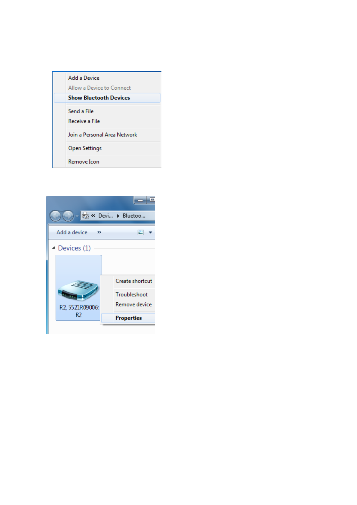
Alternatively, select Show Bluetooth Devices from the Bluetooth context menu:
In the Bluetooth Device window, right-click the device and then select Properties from
the shortcut menu.
Step 2:Configure the receiver using Trimble software
Use Trimble software (for example, Trimble TerraSync of Trimble TerraFlex software) to
configure the receiver as required. For more information, refer to the user guide for the
Trimble field software that you are using.
Configuring a PC USB port as a virtual serial port
It is possible to use the USB interface from a Trimble R2 GNSS receiver with a software
application that requires a serial port.
Trimble R2 GNSS ReceiverUser Guide | 39
Page 40

3 Configuring andusing the receiver
For example, the Trimble WinFlash utility can be run on a computer that has no physical
serial port by connecting the USB cable between the computer and the receiver.
Windows 8 operating system
1. The simplest way to install the virtual serial port for the USB interface to the receiver is
to go to the Trimble Support website (http://www.trimble.com/Support/Support_
AZ.aspx) and search for the GNSS receiver you have. In the Technical Support /
Downloads section, download the file called Windows7 USB Installer to your computer.
Note - There is no Windows8 USB Installer file; the Windows7 USB Installer file works
for Windows 8.
This file contains a Support Note and installation program.
2. Run the installation program. It will load the virtual serial port for the USB interface on
your computer.
NOTE – With Windows 8, the USB ports are often version 3.0. With Windows 8 there is a conflict
with the implementation of USB version 3.0. To workaround this, go to the computer's BIOS
settings when you start up the computer and then turn off the support for USB 3.0.
NOTE – If you have installed the Trimble WinFlash utility (www.trimble.com/support) on your
computer, then another way to install the virtual serial port for the USB interface is to run the
USB Installer program, which is located in C:\Program Files\Common Files\Trimble\USBDriver.
1. The simplest way to install the virtual serial port for the USB interface to the receiver is
to go to the Trimble Support website (www.trimble.com/support) and search for the
Trimble R2 GNSS receiver. In the Downloads section, download the file called Windows7
USB Installer to your computer.
This file contains a Support Note and installation program.
2. Run the installation program. It will load the virtual serial port for the USB interface on
your computer.
NOTE – If you have installed the Trimble WinFlash utility on your computer, then another way
to install the virtual serial port for the USB interface is to run the USB Installer program, which is
located in C:\Program Files\Common Files\Trimble\USBDriver.
If this process does not work for your computer, or if you have a different Windows
operating system on your computer, then follow the procedure below.
Windows Vista and Windows 7 operating system
1. Go to the Trimble Support website (www.trimble.com/support) and search for the
receiver you have. In the Support Notes section, download the file called GNSS Interface
Trimble R2 GNSS ReceiverUser Guide | 40
Page 41

3 Configuring andusing the receiver
to a Virtual COM port on a Computer to your computer.
2. Open the file and place the trmbUsb.inf file in a temporary folder on your computer.
3. On the computer, select Control Panel / Device Manager.
4. Click on the name of the computer and then from the Action menu, select Add Legacy
Driver.
5. A wizard prompts you to locate the TrimbleUsb.inf file. Locate the file and then follow
the prompts in the wizard to continue.
NOTE – If you are running an application such as WinFlash software on the computer and you
physically disconnect the USB cable from the computer and then reconnect it, it does not always reestablish the connection. This is because opening the serial port from the application locks the
device handle and when the USB device is disconnected, the application does not close the serial
port and the device handle is still locked. On reconnecting, the USB cable is unable to get the device
handle since it is locked. You must close the application before the reconnect to the port will work.
This limitation is due to the behavior of the Microsoft USB serial driver.
Configuring the receiver using the GNSSStatus utility
To configure a receiver using the Trimble GNSSStatus utility, you must pair the receiver
with the device that is running the GNSS Status utility, and, on Android devices, you must
enable Mock Locations.
You can connect a R2 GNSSreceiver to a handheld device or tablet powered by the
following operating systems:
l Android versions 4.1x and later
l iOS
l Windows® 7 and Windows 8.x
l Windows Embedded Handheld 6.5
The method for enabling Mock Locations differs for different Android devices. Generally,
this is done under Settings / Developer options, Allow mock locations. Refer to the
documentation for your device for specific instructions.
To use the GNSSStatus utility with the R2 receiver:
1. Make sure the device you want to use has Bluetooth wireless techology turned on.
2. .Make sure the receiver is turned on.
3. Depending on the device you want to pair the receiver with, do one of the following:
l On a device powered by the Windows 7 or 8.x operating system, Windows
Embedded Handheld 6.5, or Android versions 4.1.x or later, use the GNSSStatus
Trimble R2 GNSS ReceiverUser Guide | 41
Page 42

3 Configuring andusing the receiver
utility to pair with the receiver.
a.
Tap GNSSStatus to launch the GNSSStatus utility.
b. Tap Select new receiver. The device you are using searches for receivers within
range.
c. When the required receiver appears in the Select Receiver list, tap it, then tap the
connection icon to the right of the receiver IDto pair.
l On an iPhone or iPad, go to Settings / Bluetooth, and tap the R2 [ID] device you want
to pair with.
Connecting to a R2 GNSSreceiver
To reconnect to a receiver at any time, make sure it is turned on, then:
l On a device powered by the Windows 7 or 8.x operating system, Windows Embedded
Handheld 6.5, or Android versions 4.1.x or later, use the GNSSStatus utility to connect
with the receiver:
a.
Tap GNSSStatus to launch the GNSSStatus utility.
b. Tap the R2 [ID] at the bottom of the screen to bring up the Select Receiver list. Tap
the device [R2 ID] you want to reconnect to. Tap the connection icon to the right of
the receiver IDto connect to it.
l On an iPhone or iPad, go to Settings / Bluetooth, and tap the R2 [ID] device you want to
connect to.
Configuring the receiver using the GNSSStatus utility
To configure a receiver using the Trimble GNSSStatus utility, you must pair the receiver
with the device that is running the GNSS Status utility, and, on Android devices, you must
enable Mock Locations.
You can connect a R2 GNSSreceiver to a handheld device or tablet powered by the
following operating systems:
l Android versions 4.1x and later
l iOS
l Windows® 7 and Windows 8.x
l Windows Embedded Handheld 6.5
The method for enabling Mock Locations differs for different Android devices. Generally,
this is done under Settings / Developer options, Allow mock locations. Refer to the
documentation for your device for specific instructions.
Trimble R2 GNSS ReceiverUser Guide | 42
Page 43

3 Configuring andusing the receiver
To use the GNSSStatus utility with the R2 receiver:
1. Make sure the device you want to use has Bluetooth wireless techology turned on.
2. .Make sure the receiver is turned on.
3. Depending on the device you want to pair the receiver with, do one of the following:
l On a device powered by the Windows 7 or 8.x operating system, Windows
Embedded Handheld 6.5, or Android versions 4.1.x or later, use the GNSSStatus
utility to pair with the receiver.
a.
Tap GNSSStatus to launch the GNSSStatus utility.
b. Tap Select new receiver. The device you are using searches for receivers within
range.
c. When the required receiver appears in the Select Receiver list, tap it, then tap the
connection icon to the right of the receiver IDto pair.
l On an iPhone or iPad, go to Settings / Bluetooth, and tap the R2 [ID] device you want
to pair with.
Connecting to a R2 GNSSreceiver
To reconnect to a receiver at any time, make sure it is turned on, then:
l On a device powered by the Windows 7 or 8.x operating system, Windows Embedded
Handheld 6.5, or Android versions 4.1.x or later, use the GNSSStatus utility to connect
with the receiver:
a.
Tap GNSSStatus to launch the GNSSStatus utility.
b. Tap the R2 [ID] at the bottom of the screen to bring up the Select Receiver list. Tap
the device [R2 ID] you want to reconnect to. Tap the connection icon to the right of
the receiver IDto connect to it.
l On an iPhone or iPad, go to Settings / Bluetooth, and tap the R2 [ID] device you want to
connect to.
Downloading the GNSSStatus utility
Download the GNSSStatus utility for your device:
l for Windows, Windows Embedded Handheld, go to the product downloads page on
www.trimble.com
l for Android, go to Google Play store and search for “GNSS Status Utility"
l for iOS, go to iTunes app store and search for "GNSS Status Utility"
Trimble R2 GNSS ReceiverUser Guide | 43
Page 44

3 Configuring andusing the receiver
Using the GNSSStatus utility
On your device, tap GNSSStatus to launch the GNSSStatus utility.
If the device you are using is not connected to a R2 GNSSreceiver, the GNSSStatus utility
shows:
l Select new receiver enabling you to select a R2 GNSSreceiver to connect to
If the device you are using is connected to a R2 GNSSreceiver, the GNSSStatus utility Home
screen shows:
l The estimated GNSSaccuracy
l The R2 GNSSreceiver's battery status
l The DGNSS status
l
The menu (on tablets), or Menu icon (on smartphones and handheld devices)
l The IDof the connected R2 GNSS receiver
The menu options are described below.
Detailed status
Tap the Estimated Accuracy shown on the Home screen. Or, flick the current screen to the
right to display the menu options, or tap , then tap Detailed Status.
The Detailed Status screen shows:
l the receiver's GNSSstatus
l the satellites that are in use and being tracked . For supported constellations, refer to
the Trimble R2 GNSSreceiver's Datasheet on www.trimble.com.
l the real-time correction source in use.
l the receiver's serial number, firmware version, and battery charge status
l packets received (if you are using Internet based sources) and error messages
App settings
You can configure the GNSSStatus utility to use metric or imperial (US)units.
1.
Tap or flick the current screen to the right to display the menu options.
2. Tap App Settings. On an iOSor Android device, tap Unit System.
3. Select Metric or US.
Trimble R2 GNSS ReceiverUser Guide | 44
Page 45

3 Configuring andusing the receiver
Receiver options
You can configure the R2 GNSSreceiver to use options (subscription services)if you have
purchased them.
1.
Tap or flick the current screen to the right to display the menu options.
2. Tap Receiver Options.
3. In the Install Optionfield, enter the key you received when you purchased the option.
4. Tap Submit.
The Subscription Status is shown on the lower part of the screen.
For more information on purchasing receiver options, contact your local Trimble reseller.
Real-time config
To configure real-time correction sources:
1. If a receiver is connected, tap the DGNSSStatus shown on the Home screen. Or, flick the
current screen to the right to display the menu options, or tap , then tap Real-time
Config.
2. Tap Edit. On an iOS or Android device, tap Primary Source Type.
3. Select Internet, SBAS, or Uncorrected as the primary real-time correction source.
4. If you selected Internet as the primary source, tap the fields on the Real-time Config
screen to configure the primary source, and set a Secondary Source Type (SBAS or
Uncorrected).
5. Tap Apply.
NMEASettings
To configure the connected receiver to output specific NMEA sentences:
1.
Tap or flick the current screen to the right to display the menu options.
2. Tap NMEA Settings.
3. Configure the NMEA sentences that are needed by the workflow application. The
available settings are listed in the Available column on the left; the settings you have
selected to apply to the receiver are listed in the Selected column on the right.
l To select an individual setting, tap it in the Available list on the left, and it will move
to the Selected list.
l To remove an individual setting, tap it in the Selected list on the right , and it will
move to the Available list.
Trimble R2 GNSS ReceiverUser Guide | 45
Page 46

3 Configuring andusing the receiver
l To select all the available settings, tap the double arrow >> below the Available
column.
l To remove all the selected settings, tap the double arrow << below the Selected
column.
4. If no receiver is connected, you can save the settings; tap Save at the top right of the
screen. To apply the NMEAsettings to the receiver, make sure that the receiver is
paired with the PC and that the GNSS Status utility is connected to the receiver. Click
Apply to receiver.
5. In the Select Port screen, select the SPP port to use for NMEAconfigurations. For
instructions on configuring SPP ports with Windows COM ports for NMEA port
handling on devices powered by the Windows operating system, see Understanding
the relationship between Bluetooth Serial Port Profile (SPP) ports and Windows COM
ports , page 47.
Trimble R2 GNSS ReceiverUser Guide | 46
Page 47

3 Configuring andusing the receiver
About
The About screen shows the GNSSStatus utility version number.
Using the receiver with GIS software on Windows
Embedded Handheld and Windows devices
Using Trimble software
If you are using Trimble software on devices powered by the Windows Embedded
Handheld or Windows Desktop operating systems, you do not need to install the
GNSSStatus utility. You can connect to the R2 GNSSreceiver from within the software
when the receiver is in Bluetooth pairing mode, as with other Trimble external receivers.
Using other software with NMEA
When using software that understands NMEA for position information, you must use the
GNSS Status utility to configure the receiver to output NMEA on the correct port. Because
the receiver uses Serial Port Profile (SPP) ports, and software run on a Windows device
uses Windows COM ports, it is important to understand the relationship between
Bluetooth Serial Port Profile ports and Windows COM ports, as described below.
Understanding the relationship between Bluetooth Serial Port Profile
(SPP) ports and Windows COM ports
NOTE – This process is specific to the Windows 7 operating system; instructions are similar for
Windows 8 / 8.1 and Windows 10 operating systems.
When you first connect a R2 receiver, the Windows operating system installs the
appropriate drivers and associates Bluetooth Serial Port Profile (SPP) ports with Windows
COM ports. The receiver is listed in the Bluetooth Devices screen:
To see which Windows COM ports are associated with the device SPP ports, right-click on
the device and select Properties. Then select the Services tab.
Trimble R2 GNSS ReceiverUser Guide | 47
Page 48

3 Configuring andusing the receiver
Applications that run on Windows devices (for example, the Trimble TerraFlex software)will
see, in this example, COM6, COM9, COM10 and COM17. COM17 is the GNSS Server SPP port;
it should NOT be selected for use by applications as it is used to supply positions to
Location Services on the device. The GNSS Server port will reset to a default configuration
each time it is connected, irrespective of any changes you make.
NOTE – Different installations will result in different Windows COM port assignments.
The application you are using to collect data will have a configuration screen that will
include options such as:
Trimble R2 GNSS ReceiverUser Guide | 48
Page 49

3 Configuring andusing the receiver
In this example, the COM9 Windows COM port is selected, which corresponds to SPP2 on
the receiver.
The above diagram illustrates the overall association. The following is specific to the
example above (your Windows COM Port numbers may be different):
Bluetooth Serial Port Profile (SPP) Windows COM Port
SPP1 COM6
SPP2 COM9
SPP3 COM10
Logging data
You can log data onto the R2 GNSS receiver itself, or onto a handheld device, smartphone,
or tablet.
To log GNSSdata using the R2 GNSS receiver:
l connect the receiver to a Trimble handheld / controller using Bluetooth wireless
technology. See Configuring the receiver using Trimble software and Bluetooth
Trimble R2 GNSS ReceiverUser Guide | 49
Page 50

3 Configuring andusing the receiver
wireless technology for details on connecting the receiver. Use Trimble field software
(for example, Trimble Access software, Trimble TerraSync software, Trimble TerraFlex
software)to log GNSS data from the receiver to the handheld / controller, or to a data
card in the controller. For more information, refer to the user guide for your particular
handheld / controller, and the Trimble field software that you are using.
l Use the R2 GNSSreceiver with the Trimble DLapp on Android™ smartphones and
tablets. The Trimble DLapp is available to download from the Google Play store.
Contact your local Trimble dealer for more information on the Trimble DLapp for
Android devices.
l To log received corrections onto the internal memory, connect to the Web Interface
and go to Data Logging / Summary / Configure and select Log Received Corrections.
Trimble R2 GNSS ReceiverUser Guide | 50
Page 51

4
Default Settings
n Default receiver settings
n Resetting the receiver to factory defaults
All receiver settings are stored in application files. The default application file is stored
permanently in the receiver, and contains the factory default settings for the receiver.
Whenever the receiver is reset to its factory defaults, the current settings (stored in the
current application file, current.cfg) are reset to the values in the default application file.
You cannot modify the default application file. however, if there is a power up application
file (Power_up.cfg) in the receiver, the settings in this file can be applied immediately after
the default application file, overriding the factory defaults.
NOTE – NMEAmust be configured to use the second port; Anything configured to use the first port
will be reset when the receiver is reset.
Trimble R2 GNSS ReceiverUser Guide | 51
Page 52

Default receiver settings
These settings are defined in the default application file.
Function Settings Factory default
SV Enable - All SVs enabled
General Controls Elevation mask 10°
PDOP mask 99
RTK positioning mode Low Latency
Motion Kinematic
Input Setup Station Any
4 Default Settings
NMEA/ASCII (all
supported messages)
Streamed Output All types Off
RT17/Binary All ports Off
Reference Position Latitude 0°
Antenna Type Trimble R2 internal
All ports Off
Offset=00
Longitude 0°
Altitude 0.00 m HAE
Height (true vertical) 0.00 m
Group All
Measurement method Antenna Phase Center
Resetting the receiver to factory defaults
To reset the receiver to its factory defaults, press for 15 seconds until the LED
changes to a slow yellow flash and then release immediately.
Trimble R2 GNSS ReceiverUser Guide | 52
Page 53

NMEA Output Messages
n NMEA-0183 messages: Overview
n NMEA-0183 messages: Common message elements
n List of supported NMEA messages
This appendix describes the formats of the subset of NMEA-0183 messages that are
available for output by the receiver. For a copy of the NMEA-0183 Standard, go to the
National Marine Electronics Association website at www.nmea.org.
5
Trimble R2 GNSS ReceiverUser Guide | 53
Page 54

5 NMEA Output Messages
NMEA-0183 messages: Overview
When NMEA-0183 output is enabled, a subset of NMEA-0183 messages can be output to
external instruments and equipment connected to the receiver serial ports. These NMEA0183 messages let external devices use selected data collected or computed by the GNSS
receiver.
All messages conform to the NMEA-0183 version 3.01 format. All begin with $ and end with
a carriage return and a line feed. Data fields follow comma (,) delimiters and are variable in
length. Null fields still follow comma (,) delimiters, but contain no information.
An asterisk (*) delimiter and checksum value follow the last field of data contained in an
NMEA-0183 message. The checksum is the 8-bit exclusive of all characters in the message,
including the commas between fields, but not including the $ and asterisk delimiters. The
hexadecimal result is converted to two ASCII characters (0–9, A–F). The most significant
character appears first.
The following table summarizes the set of NMEA messages supported by the receiver.
Message Function
DP Dynamic positioning
GBS GNSS satellite fault detection (RAIM support)
GGA Time, position, and fix related data
GLL Position data: position fix, time of position fix, and status
GNS GNS Fix data
GRS GRS range residuals
GSA GPS DOP and active satellites
GST Position error statistics
GSV Number of SVs in view, PRN, elevation, azimuth, and SNR
HDT Heading from True North
LLQ Leica local position and quality
PTNL,AVR Time, yaw, tilt, range, mode, PDOP, and number of SVs for Moving Baseline
RTK
PTNL,BPQ Base station position and position quality indicator
PTNL,DG L-band corrections and beacon signal strength and related information
Trimble R2 GNSS ReceiverUser Guide | 54
Page 55

5 NMEA Output Messages
Message Function
PTNL,GGK Time, position, position type, and DOP values
PTNL,PJK Time, position, position type, and DOP values
PTNL,PJT Projection type
PTNL,VGK Time, locator vector, type, and DOP values
PTNL,VHD Heading Information
RMC Position, Velocity, and Time
ROT Rate of turn
VTG Actual track made good and speed over ground
ZDA UTC day, month, and year, and local time zone offset
To enable or disable the output of individual NMEA messages, do one of the following:
l Create an application file in the Configuration Toolbox software that contains NMEA
output settings and then send the file to the receiver.
l Add NMEA outputs in the Serial outputs tab of the GPS Configurator software and
then apply the settings.
For a copy of the NMEA-0183 Standard, go to the National Marine Electronics Association
website at www.nmea.org.
Trimble R2 GNSS ReceiverUser Guide | 55
Page 56

5 NMEA Output Messages
NMEA-0183 messages: Common message elements
Each message contains:
l a message ID consisting of $GP followed by the message type. For example, the
message ID of the GGA message is $GPGGA.
l a comma.
l a number of fields, depending on the message type, separated by commas.
l an asterisk.
l a checksum value.
The following example shows a simple message with a message ID ($GPGGA), followed by
13 fields and a checksum value:
$GPGGA,172814.0,3723.46587704,N,12202.26957864,W,2,6,1.2,18.893,M,-
25.669,M,2.0,0031*4F
Message values
NMEA messages that the receiver generates contains the following values:
Value Description
Latitude and
Longitude
Direction Direction (north, south, east, or west) is represented by a single
Time Time values are presented in Universal Time Coordinated (UTC) and
Latitude is represented as ddmm.mmmm and longitude is
represented as dddmm.mmmm, where:
l dd or ddd is degrees
l mm.mmmm is minutes and decimal fractions of minutes
character: N , S , E , or W.
are represented as hhmmss.ss, where:
l hh is hours, from 00 through 23
l mm is minutes
l ss.ss is seconds with variable length decimal-fraction of seconds
Trimble R2 GNSS ReceiverUser Guide | 56
Page 57

5 NMEA Output Messages
List of supported NMEA messages
NMEA-0183 message: DP (Dynamic Positioning)
Proprietary Fugro message
The resulting message is shorter than the maximum defined message length of 82
characters, even with mm level resolution in Latitude/Longitude.
$PFUGDP,GG,hhmmss.ss, ddmm.mmmmm,N, dddmm.mmmmm,E,
NN,Q,DD,aa.a,bb.b,ddd,rr.r
An example of the DP message string is:
$PFUGDP,GN,033615.00,3953.88002,N,10506.75324,W,13,9,FF,0.1,0.1,149,0.1*13
DP message fields
Field Meaning
0 Message ID $PFUGDP
1 Two-character code for GPS (GP), GLONASS (GL) or GNSS (GN) data
2 UTC time (hhmmss.ss)
3-4 Latitude, in degrees and decimal minutes (ddmm.mmmmm) and Latitude sign
(N/S)
5-6 Longitude, in degrees and decimal minutes (dddmm.mmmmm) and Longitude
sign (E/W)
7 Total number of satellites (GPS + GLONASS)
8 DPVOA (UK00A) quality indicator
1
9 DGNSS mode indicator (as NMEA standard for $ GNS)
10 Error ellipse standard deviation semi-major axis, in meters (aa.a)
11 Error ellipse standard deviation semi-minor axis, in meters (bb.b)
12 Direction of the error ellipse, in degrees
13 RMS value of the standard deviation of the range inputs to the navigation
1
process
1
This quality indicator is defined in Guidelines on the use of DGPS in as a positioning reference
in DP Control Systems IMCA M141, dated Oct 1997 www.imca-
Trimble R2 GNSS ReceiverUser Guide | 57
Page 58

5 NMEA Output Messages
int.com/publications/marine/imca.html.
NMEA-0183 message: DTM
The DTM message identifies the local geodetic datum and datum offsets from a reference
datum. This sentence is used to define the datum to which a position location, and
geographic locations in subsequent sentences, is referenced.
An example of the DTM message string is:
$GPDTM,W84,,0.0,N,0.0,W,0.0,W84*7D
DTM message fields
Field Meaning
0 Message ID $GPDTM
1 Local datum code (CCC):
W84 – WGS-84
W72 – WGS-72
S85 – SGS85
P90 – PE90
999 – User-defined
IHO datum code
2 Local datum subdivision code (x)
3 Latitude offset, in minutes (x.x)
4 N/S (x)
5 Longitude offset, in minutes (x.x)
6 E/W (x)
7 Altitude offset, in meters (x.x)
8 Reference datum code (CCC):
W84 – WGS-84
W72 – WGS-72
S85 – SGS85
P90 – PE90
Trimble R2 GNSS ReceiverUser Guide | 58
Page 59

NMEA-0183 message: GBS
GNSS satellite fault detection (RAIM support)
An example of the GBS message string is:
$GPGBS,015509.00,-0.031,-0.186,0.219,19,0.000,-0.354,6.972*4D
GBS message fields
Field Meaning
0 Message ID $--GBS.
Talker ID can be:
GA: Galileo
GB: Beidou
GP: GPS. To provide information specific to the GPS constellation when more
than one constellation is used for the differential position fix.
5 NMEA Output Messages
GL: GLONASS. To provide information specific to the GLONASS constellation
when more than one constellation is used for the differential position fix.
GN: Combined GNSS position. GNSS position fix from more than one
constellation, for example, GPS and GLONASS.
GQ: QZSS
1 UTC of position fix
2 Expected error in latitude, in meters, due to bias, with noise = 0
3 Expected error in longitude, in meters, due to bias, with noise = 0
4 Expected error in altitude, in meters, due to bias, with noise = 0
5 ID number of most likely failed satellite
6 Probability of missed detection of most likely failed satellite
7 Estimate of bias, in meters, on the most likely failed satellite
8 Standard deviation of bias estimate
9 The checksum data, always begins with *
If NMEA-0183 version 4.10 is selected, the 9th, 10th, and 11th fields become:
Trimble R2 GNSS ReceiverUser Guide | 59
Page 60

Field Meaning
5 NMEA Output Messages
9
10
11 The checksum data, always begins with *
System ID based on:
GPS 1
GLONASS 2
Galileo 3
Beidou 4
QZSS 0
Signal ID based on:
GPS 1
GLONASS 1
Galileo 7
Beidou Null
QZSS Null
NMEA-0183 message: GGA
Time, position, and fix related data
An example of the GBS message string is:
$GPGGA,172814.0,3723.46587704,N,12202.26957864,W,2,6,1.2,18.893,M,-25.669,M,2.0
0031*4F
NOTE – The data string exceeds the NMEA standard length.
GGA message fields
Field Meaning
0 Message ID $GPGGA
1 UTC of position fix
2 Latitude
3 Direction of latitude:
N: North
S: South
4 Longitude
Trimble R2 GNSS ReceiverUser Guide | 60
Page 61

Field Meaning
5 Direction of longitude:
E: East
W: West
6 GPS Quality indicator:
0: Fix not valid
1: GPS fix
2: Differential GPS fix (DGNSS), SBAS, OmniSTAR VBS, Beacon, RTX in GVBS mode
3: Not applicable
4: RTK Fixed, xFill
5: RTK Float, OmniSTAR XP/HP, Location RTK, RTX
6: INS Dead reckoning
5 NMEA Output Messages
7 Number of SVs in use, range from 00 through to 24+
8 HDOP
9 Orthometric height (MSL reference)
10 M: unit of measure for orthometric height is meters
11 Geoid separation
12 M: geoid separation measured in meters
13 Age of differential GPS data record, Type 1 or Type 9. Null field when DGPS is not
used.
14 Reference station ID, range 0000-4095. A null field when any reference station ID is
selected and no corrections are received. See table below for a description of the
field values.
15 The checksum data, always begins with *
NOTE – If a user-defined geoid model, or an inclined plane is loaded into the receiver, then the
height output in the NMEA GGA string is always the orthometric height (height above a geoid). The
orthometric height is output even if no user-defined geoid is loaded (there is a simplified default
geoid in the receiver), or if a user-defined geoid is loaded, or if an inclined plane is used.
When using one of the MSS (Mobile Satellite Services), the Reference Station ID field
indicates the following services:
Trimble R2 GNSS ReceiverUser Guide | 61
Page 62

Reference Station ID Service
0002 CenterPoint or ViewPoint RTX
0005 RangePoint RTX
0006 FieldPoint RTX
0100 VBS
1000 HP
1001 HP/XP (Orbits)
1002 HP/G2 (Orbits)
1008 XP (GPS)
1012 G2 (GPS)
1013 G2 (GPS/GLONASS)
5 NMEA Output Messages
1014 G2 (GLONASS)
1016 HP/XP (GPS)
1020 HP/G2 (GPS)
1021 HP/G2 (GPS/GLONASS)
NMEA-0183 message: GNS
GNSS fix data
GNSS capable receivers will always output this message with the GN talker ID
GNSS capable receivers will also output this message with other talker ID's when using
more than one constellation for the position fix
An example of the GNS message output from a GNSS capable receiver is:
$GNGNS,014035.00,4332.69262,S,17235.48549,E,RR,13,0.9,25.63,11.24,,*70<CR><LF>
$GPGNS,014035.00,,,,,,8,,,,1.0,23*76<CR><LF>
$GLGNS,014035.00,,,,,,5,,,,1.0,23*67<CR><LF>
GNS message fields
Field Meaning
0 Message ID $--GNS
Trimble R2 GNSS ReceiverUser Guide | 62
Page 63

Field Meaning
Talker ID can be:
GA: Galileo
GB: Beidou
GP: GPS
GL: GLONASS. When more than one constellation is used.
GN: Combined GNSS position, for example, GPS and GLONASS.
GQ: QZSS
1 UTC of position fix
2 Latitude
3 Direction of latitude:
5 NMEA Output Messages
N: North
S: South
4 Longitude
5 Direction of longitude:
E: East
W: West
6 Mode indicator:
l Variable character field with one character for each supported constellation.
l First character is for GPS.
l Second character is for GLONASS.
l Third character is Galileo.
l Fourth character is for Beidou.
l Fifth character is for QZSS.
l Subsequent characters will be added for new constellations.
Each character will be one of the following:
N = No fix. Satellite system not used in position fix, or fix not valid
A = Autonomous. Satellite system used in non-differential mode in position fix
D = Differential (including all OmniSTAR services). Satellite system used in
Trimble R2 GNSS ReceiverUser Guide | 63
Page 64

Field Meaning
differential mode in position fix
P = Precise. Satellite system used in precision mode. Precision mode is defined
as: no deliberate degradation (such as Selective Availability) and higher
resolution code (P-code) is used to compute position fix
R = Real Time Kinematic. Satellite system used in RTK mode with fixed integers
F = Float RTK. Satellite system used in real-time kinematic mode with floating
integers
E = Estimated (dead reckoning) Mode
M = Manual Input Mode
S = Simulator Mode
7 Number of SVs in use, range 00–99
5 NMEA Output Messages
8 HDOP calculated using all the satellites (GPS, GLONASS, and any future satellites)
used in computing the solution reported in each GNS sentence.
9 Orthometric height in meters (MSL reference)
10 Geoidal separation in meters – The difference between the earth ellipsoid
surface and mean-sea-level (geoid) surface defined by the reference datum
used in the position solution.
“-” = mean-sea-level surface below ellipsoid.
11 Age of differential data – Null if talker ID is GN, additional GNS messages follow
with Age of differential data.
12 Reference station ID1, range 0000-4095
– Null if Talker ID is GN. Additional GNS messages follow with Reference station
ID.
13 The checksum data, always begins with *
NOTE – If a user-defined geoid model, or an inclined plane is loaded into the receiver, then the
height output in the NMEA GNS string is always the orthometric height (height above a geoid). The
orthometric height is output even if no user-defined geoid is loaded (there is a default geoid in the
receiver), or if a user-defined geoid is loaded, or if an inclined plane is used.
1
When using OmniSTAR services, the Reference Station ID indicates the following services:
Trimble R2 GNSS ReceiverUser Guide | 64
Page 65

5 NMEA Output Messages
VBS 100=VBS; 1000=HP; 1001 = HP/XP (Orbits) ; 1002 = HP/G2 (Orbits); 1008 = XP (GPS); 1012
= G2 (GPS); 1013 = G2 (GPS/GLONASS); 1014 = G2 (GLONASS); 1016 = HP/XP (GPS); 1020 =
HP/G2 (GPS) ; 1021 = HP/G2 (GPS/GLONASS).
NMEA-0183 message: GSA
GPS DOP and active satellites
An example of the GSA message string is:
$GNGSA,A,3,21,5,29,25,12,10,26,2,,,,,1.2,0.7,1.0*27
$GNGSA,A,3,65,67,80,81,82,88,66,,,,,,1.2,0.7,1.0*20
GSA message fields
Field Meaning
0 Message ID $GNGSA
1 Mode 1, M = manual, A = automatic
2 Mode 2, Fix type, 1 = not available, 2 = 2D, 3 = 3D
3 PRN number, 01 through 32 for GPS, 33 through 64 for SBAS, 64+ for GLONASS
4 PDOP: 0.5 through 99.9
5 HDOP: 0.5 through 99.9
6 VDOP: 0.5 through 99.9
7 The checksum data, always begins with *
If NMEA-0183 version 4.10 is selected, the 7th and 8th fields become:
Field Meaning
7
System ID based on:
GPS 1
GLONASS 2
Galileo 3
Beidou 4
QZSS 0
8 The checksum data, always begins with *
Trimble R2 GNSS ReceiverUser Guide | 65
Page 66

5 NMEA Output Messages
NMEA-0183 message: GST
Position error statistics
An example of the GST message string is:
$GPGST,172814.0,0.006,0.023,0.020,273.6,0.023,0.020,0.031*6A
The Talker ID ($--) will vary depending on the satellite system used for the position solution:
l $GP - GPS only
l $GL - GLONASS only
l $GN - Combined
GST message fields
Field Meaning
0 Message ID $GPGST
1 UTC of position fix
2 RMS value of the pseudorange residuals; includes carrier
phase residuals during periods of RTK (float) and RTK (fixed)
processing
3 Error ellipse semi-major axis 1 sigma error, in meters
4 Error ellipse semi-minor axis 1 sigma error, in meters
5 Error ellipse orientation, degrees from true north
6 Latitude 1 sigma error, in meters
7 Longitude 1 sigma error, in meters
8 Height 1 sigma error, in meters
9 The checksum data, always begins with *
NMEA-0183 message: GSV
Satellite information
The GSV message string identifies the number of SVs in view, the PRN numbers, elevations,
azimuths, and SNR values. Example GSV message strings are:
$GPGSV,8,1,25,21,44,141,47,15,14,049,44,6,31,255,46,3,25,280,44*75
$GPGSV,8,2,25,18,61,057,48,22,68,320,52,27,34,268,47,24,32,076,45*76
Trimble R2 GNSS ReceiverUser Guide | 66
Page 67

$GPGSV,8,3,25,14,51,214,49,19,23,308,46*7E
$GPGSV,8,4,25,51,44,183,49,46,41,169,43,48,36,220,45*47
$GLGSV,8,5,25,82,49,219,52,76,22,051,41,83,37,316,51,67,57,010,51*6C
$GLGSV,8,6,25,77,24,108,44,81,10,181,46,78,1,152,34,66,18,060,45*50
$GLGSV,8,7,25,68,37,284,50*5C
$GBGSV,8,8,25,111,35,221,47,112,4,179,39,114,48,290,48*11
GSV message fields
Field Meaning
0 Message ID
1 Total number of messages of this type in this cycle
2 Message number
5 NMEA Output Messages
3 Total number of SVs visible
4 SV PRN number
5 Elevation, in degrees, 90° maximum
6 Azimuth, degrees from True North, 000° through 359°
7 SNR, 00 through 99 dB (null when not tracking)
8–11 Information about second SV, same format as fields 4 through 7
12–15 Information about third SV, same format as fields 4 through 7
16–19 Information about fourth SV, same format as fields 4 through 7
20 The checksum data, always begins with *
NOTE –
$GPGSV indicates GPS and SBAS satellites. If the PRN is greater than 32, this indicates an
SBAS PRN, 87 should be added to the GSV PRN number to determine the SBAS PRN
number.
$GLGSV indicates GLONASS satellites. 64 should be subtracted from the GSV PRN number
to determine the GLONASS PRN number.
$GBGSV indicates BeiDou satellites. 100 should be subtracted from the GSV PRN number
to determine the BeiDou PRN number.
$GAGSVindicates Galileo satellites.
$GQGSVindicates QZSS satellites.
Trimble R2 GNSS ReceiverUser Guide | 67
Page 68

5 NMEA Output Messages
NMEA-0183 message: HDT
Heading from True North
NOTE – The heading computation in this message is computed from the moving baseline vector,
which requires a two-antenna system.
An example of the HDT string is:
$GPHDT,123.456,T*00
Heading from true north message fields
Field Meaning
0 Message ID $GPHDT
1 Heading in degrees
2 T: Indicates heading relative to True North
3 The checksum data, always begins with *
NMEA-0183 message: LLQ
Leica local position and quality
An example of the LLQ message string is:
$GPLLQ,034137.00,210712,,M,,M,3,15,0.011,,M*15
Field Meaning
0 Message ID $GPLLQ
1 hhmmss.ss – UTC time of position
2 ddmmyy – UTC date
3 xxx.xxx – Grid easting (meters)
4 M – Meter, fixed text
5 xxxx.xxxx – Grid northing (meters)
6 M – Meter, fixed text
7 x – GPS quality. 0 = not valid. 1 = GPS Nav Fix. 2 = DGPS Fix. 3 = RTK Fix.
8 x – Number of satellites used in computation
Trimble R2 GNSS ReceiverUser Guide | 68
Page 69

5 NMEA Output Messages
Field Meaning
9 xx.xx – Position quality (meters)
10 xxxx.xxxx – Height (meters)
11 M – Meter, fixed text
*hh – checksum
<CR> – carriage return
<LF> – Line feed
NMEA-0183 message: PTNL,AVR
Time, yaw, tilt/roll, range for moving baseline RTK
NOTE – The heading computation in this message is computed from the moving baseline vector,
which requires a two-antenna system.
An example of the PTNL,AVR message string is:
$PTNL,AVR,212405.20,+52.1531,Yaw,-0.0806,Tilt,,,12.575,3,1.4,16*39
$PTNL,AVR,212604.30,+52.1800,Yaw,,,-0.0807,Roll,12.579,3,1.4,16*21
AVR message fields
Field Meaning
0 Message ID $PTNL,AVR
1 UTC of vector fix
2 Yaw angle, in degrees
3 Yaw
4 Tilt angle, in degrees
5 Tilt
8 Range, in meters (between antennas)
9 GPS quality indicator:
0: Fix not available or invalid
1: Autonomous GPS fix
2: Differential carrier phase solution RTK (Float)
Trimble R2 GNSS ReceiverUser Guide | 69
Page 70

5 NMEA Output Messages
Field Meaning
3: Differential carrier phase solution RTK (Fix)
4: Differential code-based solution, DGPS
10 PDOP
11 Number of satellites used in solution
12 The checksum data, always begins with *
NMEA-0183 message: PTNL,BPQ
Base station position and quality indicator
This message describes the base station position and its quality. It is used when the
moving base antenna position and quality are required on one serial port (along with a
heading message) from a receiver in heading mode.
An example of the PTNL,BPQ message string is:
$PTNL,BPQ,224445.06,021207,3723.09383914,N,12200.32620132,W,EHT-5.923,M,5*
BPQ message fields
Field Meaning
0 Talker ID
1 BPQ
2 UTC time of position fix, in hhmmss.ss format. Hours must be two numbers, so
may be padded, for example, 7 is shown as 07.
3 UTC date of position fix, in ddmmyy format. Day must be two numbers, so may
be padded, for example, 8 is shown as 08.
4 Latitude, in degrees and decimal minutes (ddmm.mmmmmmm)
5 Direction of latitude:
N: North
S: South
6 Longitude, in degrees and decimal minutes (dddmm.mmmmmmm). Should
contain 3 digits of ddd.
7 Direction of longitude:
Trimble R2 GNSS ReceiverUser Guide | 70
Page 71

5 NMEA Output Messages
Field Meaning
E: East
W: West
8 Height Ellipsoidal height of fix (antenna height above ellipsoid). Must start with
EHT.
9 M: ellipsoidal height is measured in meters
10 GPS quality indicator:
0: Fix not available or invalid
1: Autonomous GPS fix
2: Differential SBAS, or OmniSTAR VBS
4: RTK Fixed
5: OmniSTAR XP, OmniSTAR HP, CenterPoint RTX, Float RTK, or Location RTK
11 The checksum data, always begins with *
NMEA-0183 message: PTNL,GGK
Time, position, position type, DOP
An example of the PTNL,GGK message string is:
$PTNL,GGK,102939.00,051910,5000.97323841,N,00827.62010742,E,5,09,1.9,EHT150.790,M*
73
PTNL,GGK message fields
Field Meaning
0 Talker ID $PTNL
1 Message ID GGK
2 UTC time of position fix, in hhmmmss.ss format. Hours must be two numbers, so
may be padded. For example, 7 is shown as 07.
3 UTC date of position fix, in ddmmyy format. Day must be two numbers, so may
be padded. For example, 8 is shown as 08.
4 Latitude, in degrees and decimal minutes (dddmm.mmmmmmm)
5 Direction of latitude:
Trimble R2 GNSS ReceiverUser Guide | 71
Page 72

5 NMEA Output Messages
Field Meaning
N: North
S: South
6 Longitude, in degrees and decimal minutes (dddmm.mmmmmmm). Should
contain three digits of ddd.
7 Direction of longitude:
E: East
W: West
8 GPS Quality indicator:
0: Fix not available or invalid
1: Autonomous GPS fix
2: RTK float solution
3: RTK fix solution
4: Differential, code phase only solution (DGPS)
5: SBAS solution – WAAS/EGNOS/MSAS
6: RTK float or RTK location 3D Network solution
7: RTK fixed 3D Network solution
8: RTK float or RTK location 2D in a Network solution
9: RTK fixed 2D Network solution
10: OmniSTAR HP/XP solution
11: OmniSTAR VBS solution
12: Location RTK solution
13: Beacon DGPS
14: CenterPoint RTX
15: xFill
9 Number of satellites in fix
10 Dilution of Precision of fix (DOP)
11 Ellipsoidal height of fix (antenna height above ellipsoid). Must start with EHT.
12 M: ellipsoidal height is measured in meters
13 The checksum data, always begins with *
Trimble R2 GNSS ReceiverUser Guide | 72
Page 73

5 NMEA Output Messages
NOTE – The PTNL,GGK message is longer than the NMEA-0183 standard of 80 characters.
NOTE – Even if a user-defined geoid model, or an inclined plane is loaded into the receiver, then the
height output in the NMEA GGK string is always an ellipsoid height, for example, EHT24.123.
NMEA-0183 message: PTNL,PJK
Local coordinate position output
Some examples of the PTNL,PJK message string are:
$PTNL,PJK,202831.50,011112,+805083.350,N,+388997.346,E,10,09,1.5,GHT+25.478,M*77
$PTNL,PJK,010717.00,081796,+732646.511,N,+1731051.091,E,1,05,2.7,EHT+28.345,M*7C
PTNL,PJK message fields
Field Meaning
0 Message ID $PTNL,PJK
1 UTC of position fix
2 Date
3 Northing, in meters
4 Direction of Northing will always be N (North)
5 Easting, in meters
6 Direction of Easting will always be E (East)
7 GPS Quality indicator:
0: Fix not available or invalid
1: Autonomous GPS fix
2: RTK float solution
3: RTK fix solution
4: Differential, code phase only solution (DGPS)
5: SBAS solution – WAAS/EGNOS/MSAS
6: RTK Float 3D network solution
7: RTK Fixed 3D network solution
8: RTK Float 2D network solution
9: RTK Fixed 2D network solution
Trimble R2 GNSS ReceiverUser Guide | 73
Page 74

Field Meaning
10: OmniSTAR HP/XP solution
11: OmniSTAR VBS solution
12: Location RTK
13: Beacon DGPS
14: CenterPoint RTX
15: xFill
8 Number of satellites in fix
9 DOP of fix
10 Height of Antenna Phase Center (see Note below)
11 M: height is measured in meters
5 NMEA Output Messages
12 The checksum data, always begins with *
NOTE – The PTNL,PJK message is longer than the NMEA-0183 standard of 80 characters.
NOTE – If a user-defined geoid model, or an inclined plane is loaded into the receiver, then the
NMEA PJK string will always report the orthometric height (the field starts with the letters GHT). If the
latitude/longitude of the receiver is outside the user-defined geoid model bounds, then the height is
shown as ellipsoidal height (the field starts with the letters EHT).
NOTE – If the receiver does not have an application file, this string returns nothing in fields 3, 4, 5, 6,
or 10.
NMEA-0183 message: PTNL,VGK
Vector information
An example of the PTNL,VGK message string is:
$PTNL,VGK,160159.00,010997,-0000.161,00009.985,-0000.002,3,07,1,4,M*0B
PTNL,VGK message fields
Field Meaning
0 Message ID $PTNL,VGK
1 UTC of vector in hhmmss.ss format
2 Date in mmddyy format
Trimble R2 GNSS ReceiverUser Guide | 74
Page 75

Field Meaning
3 East component of vector, in meters
4 North component of vector, in meters
5 Up component of vector, in meters
6 GPS Quality indicator:
0: Fix not available or invalid
1: Autonomous GPS fix
2: RTK float solution
3: RTK fix solution
4: Differential, code phase only solution (DGPS)
5: SBAS solution – WAAS/EGNOS/MSAS
5 NMEA Output Messages
6: RTK Float 3D network solution
7: RTK Fixed 3D network solution
8: RTK Float 2D network solution
9: RTK Fixed 2D network solution
10: OmniSTAR HP/XP solution
11: OmniSTAR VBS solution
12: Location RTK
13: Beacon DGPS
14: CenterPoint RTX
15: xFill
7 Number of satellites if fix solution
8 DOP of fix
9 M: Vector components are in meters
10 The checksum data, always begins with *
NMEA-0183 message: PTNL,VHD
Heading information
NOTE – The heading computation in this message is computed from the moving baseline vector,
which requires a two-antenna system.
Trimble R2 GNSS ReceiverUser Guide | 75
Page 76

5 NMEA Output Messages
An example of the PTNL,VHD message string is:
$PTNL,VHD,030556.00,093098,187.718,-22.138,-76.929,-5.015,0.033,0.006,3,07,2.4,M*22
PTNL,VHD message fields
Field Meaning
0 Message ID $PTNL
1 VHD
2 UTC of position in hhmmss.ss format
3 Date in mmddyy format
4 Azimuth
5 Rate of change of azimuth = azimuth/time
6 Vertical angle
7 Rate of change of vertical angle = vertical/time
8 Range
9 Rate of change of range between antenna = range/time
10 GPS Quality indicator:
0: Fix not available or invalid
1: Autonomous GPS fix
2: RTK float solution
3: RTK fix solution
4: Differential, code phase only solution (DGPS)
5: SBAS solution – WAAS/EGNOS/MSAS
6: RTK Float 3D network solution
7: RTK Fixed 3D network solution
8: RTK Float 2D network solution
9: RTK Fixed 2D network solution
10: OmniSTAR HP/XP solution
11: OmniSTAR VBS solution
12: Location RTK
Trimble R2 GNSS ReceiverUser Guide | 76
Page 77

Field Meaning
13: Beacon DGPS
14: CenterPoint RTX
15: xFill
11 Number of satellites used in solution
12 PDOP
13 M
14 The checksum data, always begins with *
NMEA-0183 message: RMC
Position, velocity, and time
5 NMEA Output Messages
NOTE – The heading computation in this message is derived from consecutive positions. For
heading using a moving baseline system, see NMEA-0183 message: PTNL,AVR, page 69.
The RMC string is:
$GPRMC,123519,A,4807.038,N,01131.000,E,022.4,084.4,230394,003.1,W*6A
GPRMC message fields
Field Meaning
0 Message ID $--RMC
Talker ID can be:
GP: GPS only
GN: More than one constellation
1 UTC of position fix
2 Status A=active or V=void
3 Latitude
4 Longitude
5 Speed over the ground in knots
6 Track angle in degrees (True)
7 Date
Trimble R2 GNSS ReceiverUser Guide | 77
Page 78

5 NMEA Output Messages
Field Meaning
8 Magnetic variation, in degrees
9 The checksum data, always begins with *
NMEA-0183 message: ROT
Rate and direction of turn
NOTE – The heading computation in this message is derived from consecutive positions. For
heading using a moving baseline system, see NMEA-0183 message: PTNL,AVR, page 69.
An example of the ROT string is:
$GPROT,35.6,A*4E
ROT message fields
Field Meaning
0 Message ID $GPROT
1 Rate of turn, degrees/minutes, “–” indicates bow turns to port
2 A: Valid data
V: Invalid data
3 The checksum data, always begins with *
NMEA-0183 message: VTG
Track made good and speed over ground
NOTE – The heading computation in this message is derived from consecutive positions. For
heading using a moving baseline system, see NMEA-0183 message: PTNL,AVR, page 69.
An example of the VTG message string is:
$GPVTG,140.88,T,,M,8.04,N,14.89,K,D*05
VTG message fields
Field Meaning
0 Message ID $GPVTG
1 Track made good (degrees true)
Trimble R2 GNSS ReceiverUser Guide | 78
Page 79

Field Meaning
2 T: track made good is relative to true north
3 Track made good (degrees magnetic)
4 M: track made good is relative to magnetic nort
5 Speed, in knots
6 N: speed is measured in knots
7 Speed over ground in kilometers/hour (kph)
8 K: speed over ground is measured in kph
9 Mode indicator:
A: Autonomous mode
D: Differential mode
5 NMEA Output Messages
E: Estimated (dead reckoning) mode
M: Manual Input mode
S: Simulator mode
N: Data not valid
10 The checksum data, always begins with *
NMEA-0183 message: ZDA
UTC day, month, and year, and local time zone offset
An example of the ZDA message string is:
$GPZDA,172809.456,12,07,1996,00,00*45
ZDA message fields
Field Meaning
0 Message ID $--ZDA
Talker ID can be:
GP: GPS only
GN: More than one constellation
1 UTC
Trimble R2 GNSS ReceiverUser Guide | 79
Page 80

5 NMEA Output Messages
Field Meaning
2 Day, ranging between 01 and 31
3 Month, ranging between 01 and 12
4 Year
5 Local time zone offset from GMT, ranging from 00 through ±13 hours
6 Local time zone offset from GMT, ranging from 00 through 59 minutes
7 The checksum data, always begins with *
Fields 5 and 6 together yield the total offset. For example, if field 5 is -5 and field 6 is +15,
local time is 5 hours and 15 minutes earlier than GMT.
1
This is the same as the definit ion in the GST message i n the NMEA 183 St andard For Interf acing Marine Electronic Devices f rom v ersion 2.20, dated January 1 1997 www.nmea.org/0183.htm.
Trimble R2 GNSS ReceiverUser Guide | 80
Page 81

6
RTCM Output
n Generated messages
Generated messages
Messages that are generated when you select a specific RTCM version are shown in the
following table. For details of the individual messages, refer to the RTCMdocumentation at
www.rtcm.org.
Selection Message
Version 2 1 3 22 59
USCG, 9-3 3 9-3
RTCM/RTK, 2.2+2.3 1 3 18 19 22 23 24 59
RTK Only, 2.2+2.3 3 18 19 22 23 24 59
RTCM/RTK, 2.3 18 19 23 24
RTK Only, 2.3 18 19 22
RTCM/RTK, 2.2 1 3 18 19 22 59
RTK Only, 2.2 3 18 19 22 59
RTCM/RTK, 2.1 1 3 18 19 22 59
RTK Only, 2.1 3 18 19 22 59
RTCM/RTK, 3.x 1004 1006 1008 1012 1013 1033
Trimble R2 GNSS ReceiverUser Guide | 81
Page 82

7
Troubleshooting
n Troubleshooting LED conditions
n Troubleshooting receiver issues
This chapter provides a brief overview problems and causes. Please read this section
before you contact Technical support, page 17.
Troubleshooting LED conditions
The receiver has a simple display panel with an LED to indicate the current status of the
receiver. If you need more detailed information about what the receiver is doing, use a
Trimble controller and Trimble field software (connected to the receiver using Bluetooth
wireless technology), or access all configuration settings by connecting the receiver to your
smart phone or laptop computer via Configuring the receiver using Wi-Fi and the Web
Interface, page 35.
The LED is green and flashing fast
Possible cause Solution
The receiver is in
Monitor mode, ready
for new firmware to
be loaded or new
options to be added.
Turn on or turn off the receiver.
If that does not fix the problem, load the latest version of the
firmware, which you can download from the R2 GNSS receiver's
Downloads page on the Trimble website.
Trimble R2 GNSS ReceiverUser Guide | 82
Page 83

7 Troubleshooting
Troubleshooting receiver issues
This section describes some possible receiver issues, possible causes, and how to solve
them.
The receiver does not turn on
Possible cause Solution
External power
is too low.
Internal power
is too low.
External power
is not properly
connected.
Faulty external
power cable.
Check the charge on the external power supply, and check the
fuse if applicable. If required, replace the battery.
Do the following:
l Check the charge on the internal batteries and replace if
required.
l Ensure battery contacts are clean.
Check that the USB connection is secured properly.
Try a different cable.
The receiver is not responding
Possible cause Solution
The receiver
needs a soft
reset.
Turn off the receiver and then turn it back on again. For more
information, see Button functions, page 33.
The receiver
needs a full
reset.
Press the Power button for 30 seconds. For more information, see
Button functions, page 33.
The rover receiver is not receiving radio
Possible cause Solution
Reference receiver is not
broadcasting.
Incorrect over air baud rates
between reference and rover.
Ensure the reference base GNSS receiver is set up,
powered, and transmitting GNSS corrections.
Connect to the roving receiver’s radio and check to
ensure it has the same setting as the reference receiver.
Trimble R2 GNSS ReceiverUser Guide | 83
Page 84

Possible cause Solution
7 Troubleshooting
Incorrect port settings
between roving external radio
and receiver.
Incorrect message type
selected
If the radio is receiving data (the Power LED is flashing a
slow green) and the receiver is not getting radio
communications, use the Trimble Access software to
check that the port settings are correct.
The Broadcast format must be the same on both the
reference receiver and the rover(s).
Connect to the rover receiver using the Trimble Access
software to ensure that the R2 rover receiver Broadcast
format has the same settings as the reference receiver.
Check under Settings / Survey Styles / RTK / Rover
Options / Broadcast Format = CMRx (for example).
Trimble R2 GNSS ReceiverUser Guide | 84
Page 85

 Loading...