

Page 1

AgGPS™ 124 / 132
Operation Manual
Part Number: 38747-00
Revision: A
Date: Februa ry 1999
Trimble Navigation Limited
645 North Mary Avenue
Post Office Box 3642
Sunnyvale, CA 94088-3642
U.S.A.
+1-800-827-8000 in North America
+1-408-481-8000 International
FAX: +1-408-481-7744
www.trimble.com
Trimble
Precision Agricultural Systems
9290 Bond Street, Suite 102
Overland Park, KS 66214
U.S.A.
+1-800-865-7438 in North America
+1-913-495-2700 International
FAX: +1-913-495-2750
Trimble Navigation Europe Limited
Page 2

Trimble House, Meridian Office Park
Osborn Way, Hook
Hampshire RG27 9HX
ENGLAND
+44-1256-760-1 50
FAX: +44-1256-760-148
Trimble Navigation Singapore PTE Limited
79 Anson Road
#05-02
Singapore 079906
SINGAPORE
+65-325-5668
FAX: +65-225-9989
Trimble Japan K.K.
Sumitomo Hamamatsu-cho, Building 10F
1-18-16 Hamamatsu-cho Minato-ku
Tokyo 105
JAPAN
+81-3-5472-0880
FAX: +81-3-5472-2326
Trimble Navigation New Zealand Limited
11 Birmingha m Dr i ve
P.O. Box 8729 Riccarton
Christchurch
NEW ZEALAND
+64-3-339-1400
FAX: +64-3-339-1417
Copyrights
© 1999 Trimble Navigation Limited. All rights reserved. No part of this manual may be
copied, photocopied, reproduced, translated, or reduced to any electronic medium or machinereadable form without prior written consent from Trimble Navigation Limited.
Printed in the United States of America. Printed on recycled paper.
Page 3

Release Notice
This is the February 1999 release (Revision A) of the
AgGPS 124/132 Operation Manual
,
part number 38747-00.
Trademarks
Trimble and the Trimble logo are t rademarks of Trimble Navigation Limited, registered in the
United States and other countries.
GPS, The Choice, and TSIP are trademarks of Trimble Navigation Limited.
Ag
Microsoft, MS-DOS, Windows, Windows 95, and Windo w s NT are registered trademarks or
trademarks of Microsoft Corporation. LandStar is a trademark and a service mark of Racal
NCS, Inc. Intel is a trademark of Intel Corporation. All other brand names are trademarks of
their respective holders.
Disclaimer of Warranty
E
XCEPT AS INDICATED IN
F
IRMWARE AND DOCUMENTATION IS PROVIDED “AS IS” AND WITHOUT EXPRESS OR LIMITED
WARRANTY OF ANY KIND BY EITHER TRIMBLE NAVIGATION LIMITED OR ANYONE WHO HAS
BEEN INVOLVED IN ITS CREATION, PRODUCTION, OR DISTRIBUTION INCLUDING BUT NOT
LIMITED TO THE IMPLIED WARRANTIES OF MERCHANTABILITY AND FITNESS FOR A PARTICULAR
PURPOSE
H
ARDWARE
NOT ALLOW THE EXCLUSION OF IMPLIED WARRANTIES, SO THE ABOVE EXCLUSION MAY NOT
APPLY TO YOU
. THE
ENTIRE RISK, AS TO THE QUALITY AND PERFORMANCE OF THE TRIMBLE
, S
OFTWARE
.
“L
IMITED WARRANTY” HEREIN
, F
IRMWARE AND DOCUMENTATION, IS WITH YOU
, T
RIMBLE HARDWARE
, S
OFTWARE
. S
OME STATES DO
,
Limitation of Liability
I
N NO EVENT WILL TRIMBLE NAVIGATION LIMITED OR ANY PERSON INVOLVED IN THE
CREATION, PRODUCTION, OR DISTRIBUTION OF THE TRIMBLE SOFTWARE BE LIABLE TO YOU ON
ACCOUNT OF ANY CLAIM FOR ANY DAMAGES, INCLUDING ANY LOST PROFITS, LOST SAVINGS
OR OTHER SPECIAL, INCIDENTAL, CONSEQUENTIAL, OR EXEMPLARY DAMAGES, INCLUDING BUT
NOT LIMITED TO ANY DAMAGES ASSESSED AGAINST OR PAID BY YOU TO ANY THIRD PARTY
RISING OUT OF THE USE, LIABILITY TO USE, QUALITY OR PERFORMANCE OF SUCH TRIMBLE
S
OFTWARE AND DOCUMENTATION, EVEN IF TRIMBLE NAVIGATION LIMITED OR ANY SUCH
PERSON OR ENTITY HAS BEEN ADVISED OF THE POSSIBILITY OF DAMAGES, OR FOR ANY CLAIM
BY ANY OTHER PARTY
LIABILITY FOR INCIDENTAL OR CONSEQUENTIAL DAMAGES SO, THE ABOVE LIMITATIONS MAY
NOT APPLY TO YOU
. S
OME STATES DO NOT ALLOW THE LIMITATION OR EXCLUSION OF
.
,
,
Page 4

Software and Firmware Limited Warranty
Trimble Navigation Limited warrants that Software and Firmware products will substantially
conform to the published specifications provided it is used with the Trimble products,
computer products, and oper ating s ystem for which it was designed. For a peri od of ninety (9 0)
days, commencing thirty (30) days after shipment from Trimble, Trimble also warrants that the
magnetic media on which Software and Firmware are distributed and the documentation are
free from defects in materials and workmanship. During the ninety (90) day warranty period,
Trimble will replace defectiv e media or documentation, or correct substantial program errors at
no charge. If Trimble is unable to replace defective media or documentation, or correct
program errors, Trimble will refund the price paid for The Software. These are your sole
remedies for any breach in warranty.
Hardware Limited Warranty
Trimble Navigation Limited products are warranted against defects in material and
workmanship for a period of one year. The warranty period shall commence thirty (30) days
after shipment from Trimble’s factory. Warranty service will be provided at a designated
Trimble Service Center . T rimble will at its option either repair or replace products that prove to
be defective. The Customer shall pay all shipping charges for products return ed to Trimble for
warranty service. Trimble shall pay all shipping charges for the return of products to the
Customer.
The above warranty shall not apply to defects resulting from:
1. Improper or inadequate maintenance by the buyer
2. Buyer-supplied software or interfacing
3. Unauthorized modification or misuse
4. Operation outside of the environmental specifications of the product
5. Improper installation, where applicable
6. Lightning or other electrical discharge
7. Fresh or salt water immersion or spray
8. Normal wear and tear on consumable parts (for example, batteries)
No other warranty is expressed or implied. Trimble Navigation Limited specifically disclaims
the implied warranties of fitness for a particular purpose and merchantability.
Page 5

Contents
About This Manual
Scope and Audience . . . . . . . . . . . . . . . . . . . . . . . . .xix
Organization . . . . . . . . . . . . . . . . . . . . . . . . . . . . .xx
Related Information . . . . . . . . . . . . . . . . . . . . . . . . .xxi
Other Information . . . . . . . . . . . . . . . . . . . . . . . . . .xxi
Technical Assistance . . . . . . . . . . . . . . . . . . . . . . . . .xxii
Reader Comment Form. . . . . . . . . . . . . . . . . . . . . . . .xxiii
Document Conventions. . . . . . . . . . . . . . . . . . . . . . . .xxiii
Warnings, Cautions, Notes, and Tips. . . . . . . . . . . . . . . . .xxiv
Update Notes . . . . . . . . . . . . . . . . . . . . . . .xxi
World Wide Web (WWW) Site . . . . . . . . . . . . . .xxi
File Transfer Protocol (FTP) Site . . . . . . . . . . . . .xxi
1 Overview
1.1 Differential GPS Positioning . . . . . . . . . . . . . . . . . . . . .1-3
1.1.1 Sources of GPS Error . . . . . . . . . . . . . . . . . . .1-3
1.1.2 DGPS Accuracy . . . . . . . . . . . . . . . . . . . . . .1-4
1.2 Measuring GPS Accuracy . . . . . . . . . . . . . . . . . . . . . .1-7
1.2.1 Receiving Beacon DGPS . . . . . . . . . . . . . . . . .1-7
1.2.2 Receiving Satellite DGPS (AgGPS 132 only). . . . . . .1-9
1.3 Standard Features. . . . . . . . . . . . . . . . . . . . . . . . . . .1-10
Ag
GPS 124/132 Operation Manual v
Page 6

Contents
1.4 Receive r Enhancements . . . . . . . . . . . . . . . . . . . . . . .1-11
1.4.1 Fast Rate (P/N 33176-10) . . . . . . . . . . . . . . . . .1-11
1.4.2 Differential Base Station (P/N 33176-30) . . . . . . . . .1-11
1.4.3 Everest Technology (P/N 33176-40) . . . . . . . . . . .1-11
1.5 Application Options . . . . . . . . . . . . . . . . . . . . . . . . .1-1 2
1.5.1 Parallel Swathing (P/N 34623) . . . . . . . . . . . . . .1-12
1.5.2 Ag Field Pack (P/N 32294) . . . . . . . . . . . . . . . .1-12
1.6 Receive r Connections . . . . . . . . . . . . . . . . . . . . . . . .1-13
1.6.1 ASCII, TSIP, and RTCM Input . . . . . . . . . . . . . .1-14
1.6.2 RTCM, TSIP and NMEA Output . . . . . . . . . . . . .1-14
1.6.3 1 PPS Output . . . . . . . . . . . . . . . . . . . . . . .1-14
2 Installing the AgGPS Receiver
2.1 Unpacking and Inspecting the Shipment . . . . . . . . . . . . . . .2-1
2.1.1 Opening the Shipping Carton . . . . . . . . . . . . . . .2-2
2.1.2 Reporting Shipping Problems . . . . . . . . . . . . . . .2-4
2.2 Installation Guidelines . . . . . . . . . . . . . . . . . . . . . . . .2-5
2.2.1 Choosing a Location. . . . . . . . . . . . . . . . . . . .2-5
2.2.2 Considering Environmental Conditions . . . . . . . . . .2-5
2.3 Mounting the Receiver . . . . . . . . . . . . . . . . . . . . . . . .2-6
2.4 Mounting the Antenna . . . . . . . . . . . . . . . . . . . . . . . .2-6
2.4.1 Sources of Electrical Interference . . . . . . . . . . . . .2-7
2.5 Routing and Connecting the Antenna Cable . . . . . . . . . . . . .2-8
2.6 Connecting External Devices. . . . . . . . . . . . . . . . . . . . .2-9
2.6.1 Connecting the Standard Data/Power Cable
(P/N 30945) . . . . . . . . . . . . . . . . . . . . . . . .2-10
2.6.2 Connecting the Optional CASE AFS Power/Data Cable
(P/N 32609) . . . . . . . . . . . . . . . . . . . . . . . .2-12
2.6.3 Connecting the Optional John Deere GreenStar Data Cable
(P/N 34189) . . . . . . . . . . . . . . . . . . . . . . . .2-13
vi
Ag
GPS 124/132 Operation Manual
Page 7

2.6.4 Connecting the Optional Ag Leader Power/Data Cable
(P/N 30660) . . . . . . . . . . . . . . . . . . . . . . . .2-15
2.6.5 Connecting the Optional Power/Data RTCM/NMEA Cable
(P/N 32015) . . . . . . . . . . . . . . . . . . . . . . . .2-16
2.6.6 Connecting the Optional RDS Cable (P/N 35142) . . . .2-17
2.6.7 Connecting the Optional Windows CE with
Cigarette Power Adapter Cable (P/N 35283) . . . . . . .2-18
2.6.8 Connecting the Optional Windows CE Cable
(P/N 30661) . . . . . . . . . . . . . . . . . . . . . . . .2-18
3 Getting Started
3.1 Using the Front Pa nel. . . . . . . . . . . . . . . . . . . . . . . . .3-1
3.1.1 Viewing Status Screens . . . . . . . . . . . . . . . . . .3-3
3.2 The Home Screen. . . . . . . . . . . . . . . . . . . . . . . . . . .3-5
3.2.1 Beacon and Satellite Mode Home Screens . . . . . . . .3-6
Contents
3.3 Below Home Screen Configurables . . . . . . . . . . . . . . . . .3-11
3.3.1 Contrast . . . . . . . . . . . . . . . . . . . . . . . . . .3-11
3.3.2 Units . . . . . . . . . . . . . . . . . . . . . . . . . . . .3-12
3.3.3 Configuration Lockout Screen. . . . . . . . . . . . . . .3-13
3.3.4 Language Screen. . . . . . . . . . . . . . . . . . . . . .3-14
4 Operation Screens
4.1 Utility Screens . . . . . . . . . . . . . . . . . . . . . . . . . . . .4-2
4.1.1 Area Calculation. . . . . . . . . . . . . . . . . . . . . .4-3
4.1.2 Adjusted Area . . . . . . . . . . . . . . . . . . . . . . .4-4
4.1.3 Path Length . . . . . . . . . . . . . . . . . . . . . . . .4-5
4.1.4 Perimeter. . . . . . . . . . . . . . . . . . . . . . . . . .4-5
4.1.5 Segment Length . . . . . . . . . . . . . . . . . . . . . .4-5
Ag
GPS 124/132 Operation Manual vii
Page 8

Contents
5Status
5.1 GPS Status Screens. . . . . . . . . . . . . . . . . . . . . . . . . .5-3
5.1.1 Location . . . . . . . . . . . . . . . . . . . . . . . . . .5-4
5.1.2 Altitude . . . . . . . . . . . . . . . . . . . . . . . . . .5-5
5.1.3 Velocity . . . . . . . . . . . . . . . . . . . . . . . . . .5-6
5.1.4 GPS Satellite Information . . . . . . . . . . . . . . . . .5-7
5.1.5 DOPs. . . . . . . . . . . . . . . . . . . . . . . . . . . .5-9
5.2 Beacon DGPS Status (Beacon Mode Only) . . . . . . . . . . . . .5-10
5.2.1 Beacon Status . . . . . . . . . . . . . . . . . . . . . . .5-11
5.2.2 Alternate Beacon . . . . . . . . . . . . . . . . . . . . .5-12
5.2.3 DGPS Data Source . . . . . . . . . . . . . . . . . . . .5-13
5.2.4 DGPS Age . . . . . . . . . . . . . . . . . . . . . . . . .5-14
5.3 Satellite DGPS Status (AgGPS 132 in Satellite Mode Only). . . . .5-15
5.3.1 Satellite Differential Status . . . . . . . . . . . . . . . .5-16
5.3.2 Service Provider ID . . . . . . . . . . . . . . . . . . . .5-17
5.3.3 DGPS Data Source . . . . . . . . . . . . . . . . . . . .5-18
5.3.4 DGPS Age . . . . . . . . . . . . . . . . . . . . . . . . .5-19
5.3.5 Racal-LandStar Service Info . . . . . . . . . . . . . . .5-20
5.3.6 OmniSTAR Service Info. . . . . . . . . . . . . . . . . .5-2 1
5.3.7 Service ID and Initialization Vector (IV) . . . . . . . . .5-22
5.4 Receive r Status . . . . . . . . . . . . . . . . . . . . . . . . . . . .5-23
5.4.1 Time Screen . . . . . . . . . . . . . . . . . . . . . . . .5-23
5.4.2 Date and GPS Week . . . . . . . . . . . . . . . . . . . .5-24
5.4.3 Receive r Serial Number . . . . . . . . . . . . . . . . . .5-25
5.4.4 Firmware Version and Release Date. . . . . . . . . . . .5-26
5.4.5 Receive r Options. . . . . . . . . . . . . . . . . . . . . .5-27
5.4.6 System Voltages . . . . . . . . . . . . . . . . . . . . . .5-28
5.4.7 Incident Report . . . . . . . . . . . . . . . . . . . . . .5-29
5.5 CAN Status . . . . . . . . . . . . . . . . . . . . . . . . . . . . . .5-29
5.5.1 Channel A Status . . . . . . . . . . . . . . . . . . . . .5-30
viii
Ag
GPS 124/132 Operation Manual
Page 9

5.5.2 Channel B Status . . . . . . . . . . . . . . . . . . . . .5-31
6 Configuring the AgGPS 124 and 132 Receiver
Contents
6.1 Config uri ng the
GPS Receiver . . . . . . . . . . . . . . . . . .6-1
Ag
6.1.1 Using the Keypad to Change Configuration Settings . . .6-2
6.2 GPS Configuration . . . . . . . . . . . . . . . . . . . . . . . . . .6-3
6.2.1 Restore Defaults . . . . . . . . . . . . . . . . . . . . . .6-3
6.2.2 GPS Mode . . . . . . . . . . . . . . . . . . . . . . . . .6-4
6.2.3 System Masks . . . . . . . . . . . . . . . . . . . . . . .6-5
6.2.4 PDOP Settings. . . . . . . . . . . . . . . . . . . . . . .6-6
6.2.5 PV Filter and Position Rate . . . . . . . . . . . . . . . .6-7
6.2.6 Dynamic Mode . . . . . . . . . . . . . . . . . . . . . .6-8
6.3 DGPS Configuration . . . . . . . . . . . . . . . . . . . . . . . . .6-8
6.3.1 DGPS Mode . . . . . . . . . . . . . . . . . . . . . . . .6-9
6.3.2 DGPS Correction Age. . . . . . . . . . . . . . . . . . .6-10
6.3.3 DGPS Source (AgGPS 132 only) . . . . . . . . . . . . .6-10
6.3.4 Beacon Mode . . . . . . . . . . . . . . . . . . . . . . .6-11
6.3.5 EZ Beacon 0 . . . . . . . . . . . . . . . . . . . . . . . .6-12
6.3.6 EZ Beacon 1 . . . . . . . . . . . . . . . . . . . . . . . .6-13
6.3.7 Manual Beacon Frequencies. . . . . . . . . . . . . . . .6-14
6.3.8 Easy Satellite DGPS Configuration (AgGPS 132 Only) .6-15
6.3.9 Satellite Frequency (AgGPS 132 Only) . . . . . . . . . .6-16
6.3.10 Satellite Baud . . . . . . . . . . . . . . . . . . . . . . .6-17
6.3.11 OmniSTAR Activation. . . . . . . . . . . . . . . . . . .6-17
6.3.12 Racal Solution . . . . . . . . . . . . . . . . . . . . . . .6-18
6.4 Configuring Port Parameters . . . . . . . . . . . . . . . . . . . . .6-19
6.4.1 Setting the Port Input Parameters . . . . . . . . . . . . .6-20
6.4.2 Setting the Port Output Parameter . . . . . . . . . . . . .6-21
6.4.3 NMEA 1 Settings . . . . . . . . . . . . . . . . . . . . .6-22
6.4.4 NMEA 2 Settings . . . . . . . . . . . . . . . . . . . . .6-23
Ag
GPS 124/132 Operation Manual ix
Page 10

Contents
6.4.5 NMEA 3 Settings . . . . . . . . . . . . . . . . . . . . .6-23
6.4.6 Message Rate . . . . . . . . . . . . . . . . . . . . . . .6-24
6.5 Configuring CAN Parameters . . . . . . . . . . . . . . . . . . . .6-25
6.5.1 CAN Rate . . . . . . . . . . . . . . . . . . . . . . . . .6-26
6.5.2 Address . . . . . . . . . . . . . . . . . . . . . . . . . .6-26
6.5.3 Message Tape . . . . . . . . . . . . . . . . . . . . . . .6-27
6.5.4 Interval. . . . . . . . . . . . . . . . . . . . . . . . . . .6-28
6.6 Base Station Configuration . . . . . . . . . . . . . . . . . . . . . .6-29
6.6.1 Base Location . . . . . . . . . . . . . . . . . . . . . . .6-30
6.6.2 Enabling Base Mode. . . . . . . . . . . . . . . . . . . .6-34
6.6.3 Port A Output . . . . . . . . . . . . . . . . . . . . . . .6-35
6.6.4 Port B Output . . . . . . . . . . . . . . . . . . . . . . .6-35
7 Troubleshooting
7.1 Increasing GPS Accuracy . . . . . . . . . . . . . . . . . . . . . .7-1
7.2 Intermittent GPS Loss . . . . . . . . . . . . . . . . . . . . . . . .7-3
7.3 Power Lines and Strong Magnetic Fields . . . . . . . . . . . . . .7-3
7.4 Choosing an Antenna Location. . . . . . . . . . . . . . . . . . . .7-4
7.5 Checking for Antenna Cable Failure . . . . . . . . . . . . . . . . .7-4
7.6 Why Beacon DGPS Works In Some Places But Not Others. . . . .7-4
7.7 Reducing Engine Noise. . . . . . . . . . . . . . . . . . . . . . . .7-5
7.8 Determining if the Beac on is Operable. . . . . . . . . . . . . . . .7-5
7.9 Losing the Beacon Signal at Night . . . . . . . . . . . . . . . . . .7-5
7.10 Using the Optional TSIP Talker Software . . . . . . . . . . . . . .7-6
7.11 Why Satellite DGPS Wo rks in Some Places But Not Others . . . .7-6
7.12 Interfacing the Receiver With Other RTCM Sources . . . . . . . .7-6
7.13 Verifying the RTCM Source is Outputting Messages . . . . . . . .7-7
7.14 Verifying the Unit is Outputting NMEA Messages . . . . . . . . .7-7
7.15 Losing Configur ation Settings When the Receiver is Powered Off .7-7
7.16 The Receiver Front Bulges Out. . . . . . . . . . . . . . . . . . . .7-8
x
Ag
GPS 124/132 Operation Manual
Page 11

7.17 Restoring the Receiver to Factory Defaults . . . . . . . . . . . . .7-8
7.18 Troubleshooting Guides . . . . . . . . . . . . . . . . . . . . . . .7-9
A Specifications
B Receiver Defaults
C Cables and Connectors
C.1 Port A and Port B Connectors . . . . . . . . . . . . . . . . . . . .C-2
C.2 Standard Data/Power Cable . . . . . . . . . . . . . . . . . . . . .C-3
C.3 Ag Leader Interface Cable . . . . . . . . . . . . . . . . . . . . . .C-4
C.4 Dual Data Interface Cable . . . . . . . . . . . . . . . . . . . . . .C-5
C.5 Case AFS Cable . . . . . . . . . . . . . . . . . . . . . . . . . . .C-6
C.6 John Deere GreenStar Data Cable . . . . . . . . . . . . . . . . . .C-6
Contents
C.7 RDS Data Power Cable. . . . . . . . . . . . . . . . . . . . . . . .C-7
C.8 Windows CE Cable. . . . . . . . . . . . . . . . . . . . . . . . . .C-8
D NMEA-0183 Sentences
D.1 NMEA-0183 Sentence Structure . . . . . . . . . . . . . . . . . . .D-1
D.1.1 Symbols and Delimiters . . . . . . . . . . . . . . . . . .D-3
D.1.2 Checksum Values . . . . . . . . . . . . . . . . . . . . .D-4
D.1.3 Field Formats . . . . . . . . . . . . . . . . . . . . . . .D-4
D.1.4 Null Fields . . . . . . . . . . . . . . . . . . . . . . . . .D-4
D.1.5 Talker ID Codes . . . . . . . . . . . . . . . . . . . . . .D-5
D.1.6 Latitude and Longitude Values . . . . . . . . . . . . . .D-5
D.1.7 Time Values . . . . . . . . . . . . . . . . . . . . . . . .D-5
D.1.8 Other Values . . . . . . . . . . . . . . . . . . . . . . . .D-6
D.1.9 Reading NMEA String Format . . . . . . . . . . . . . .D-6
D.2 NMEA Sentence Summary. . . . . . . . . . . . . . . . . . . . . .D-6
D.3 ALM Sentence . . . . . . . . . . . . . . . . . . . . . . . . . . . .D-8
Ag
GPS 124/132 Operation Manual xi
Page 12

Contents
D.4 GBS Sentence . . . . . . . . . . . . . . . . . . . . . . . . . . . .D-9
D.5 GGA Sentence . . . . . . . . . . . . . . . . . . . . . . . . . . . .D-10
D.6 GLL Sentence . . . . . . . . . . . . . . . . . . . . . . . . . . . .D-11
D.7 GRS Sentence . . . . . . . . . . . . . . . . . . . . . . . . . . . .D-12
D.8 GSA Sentence . . . . . . . . . . . . . . . . . . . . . . . . . . . .D-13
D.9 GST Sentence. . . . . . . . . . . . . . . . . . . . . . . . . . . . .D-14
D.10 GSV Sentence . . . . . . . . . . . . . . . . . . . . . . . . . . . .D-15
D.11 MSS Sentence . . . . . . . . . . . . . . . . . . . . . . . . . . . .D-16
D.12 RMC Sentence . . . . . . . . . . . . . . . . . . . . . . . . . . . .D-17
D.13 VTG Sentence . . . . . . . . . . . . . . . . . . . . . . . . . . . .D-19
D.14 XTE Sentence . . . . . . . . . . . . . . . . . . . . . . . . . . . .D-20
D.15 ZDA Sentence . . . . . . . . . . . . . . . . . . . . . . . . . . . .D-21
D.16 PTNLAG001 Proprietary Sentence. . . . . . . . . . . . . . . . . .D-22
D.17 PTNLID Proprietary Sentence . . . . . . . . . . . . . . . . . . . .D-23
D.18 PTNLDG Proprietary Sentence . . . . . . . . . . . . . . . . . . .D-24
D.19 PTNL,GGK Sentence. . . . . . . . . . . . . . . . . . . . . . . . .D-26
D.20 PTNLSM Proprietary Sentence . . . . . . . . . . . . . . . . . . .D-27
E Flash Loader 100
E.1 Connecting to the Flash Loader Software . . . . . . . . . . . . . .E-2
E.2 Using Flash Loader 100 . . . . . . . . . . . . . . . . . . . . . . .E-3
E.3 Running Flash Loader 100 . . . . . . . . . . . . . . . . . . . . . .E-4
F Activating a Satellite DGPS Service
F.1 OmniSTAR Activation . . . . . . . . . . . . . . . . . . . . . . . .F-3
F.2 Racal Activation . . . . . . . . . . . . . . . . . . . . . . . . . . .F-5
xii
Ag
GPS 124/132 Operation Manual
Page 13

List of Figures
Figure 1-1
Figure 1-2 Back Panel . . . . . . . . . . . . . . . . . . . . . 1-13
Figure 2-1 Antenna Cable Connections . . . . . . . . . . . . . . 2-8
Figure 2-2 External Device Cable Connections . . . . . . . . . . . 2-10
Figure 2-3 CASE AFS Power/Data Cable Connection . . . . . . . . 2-12
Figure 2-4 GreenStar Data Cable Connection . . . . . . . . . . . . 2-13
Figure 2-5 Ag Leader Power/Data Cable Connections . . . . . . . . 2-15
Figure 2-6 Power/Data RTCM/NMEA Cable Connections. . . . . . . 2-16
Figure 3-1 AgGPS Screen Hierarchy . . . . . . . . . . . . . . . 3-2
Figure 3-2
Figure 3-3 Home Screen Hierarchy . . . . . . . . . . . . . . . . 3-5
Figure 3-4 GPS Status . . . . . . . . . . . . . . . . . . . . . 3-7
Figure 3-5 Beacon DGPS Status . . . . . . . . . . . . . . . . . 3-8
Figure 3-6 Satellite DGPS Status. . . . . . . . . . . . . . . . . 3-9
Figure 4-1 Operation Screen Hierarchy . . . . . . . . . . . . . . 4-1
Figure 4-2 Area Calculation Screen. . . . . . . . . . . . . . . . 4-3
GPS Receiver. . . . . . . . . . . . . . . . . . . 1-1
Ag
GPS 124 and 132 Receiver Front Panel. . . . . . . . . 3-3
Ag
Figure 5-1 Status Screen Hierarchy . . . . . . . . . . . . . . . . 5-2
Figure 5-2 Location . . . . . . . . . . . . . . . . . . . . . . 5-4
Figure 5-3 Altitude . . . . . . . . . . . . . . . . . . . . . . 5-5
Figure 5-4 Velocity . . . . . . . . . . . . . . . . . . . . . . 5-6
Figure 5-5 GPS Satellite Information . . . . . . . . . . . . . . . 5-7
Figure 5-6 DOPs . . . . . . . . . . . . . . . . . . . . . . . 5-9
Figure 5-7 Beacon Status. . . . . . . . . . . . . . . . . . . . 5-11
Ag
GPS 124/132 Operation Manual xiii
Page 14

List of Figures
Figure 5-8 Alternate Beacon . . . . . . . . . . . . . . . . . . 5-12
Figure 5-9 DGPS Data Source. . . . . . . . . . . . . . . . . . 5-13
Figure 5-10 DGPS Age . . . . . . . . . . . . . . . . . . . . . 5-14
Figure 5-11 Satellite Differential Status. . . . . . . . . . . . . . . 5-16
Figure 5-12 Service Provider ID . . . . . . . . . . . . . . . . . 5-17
Figure 5-13 DGPS Data Source. . . . . . . . . . . . . . . . . . 5-18
Figure 5-14 DGPS Age . . . . . . . . . . . . . . . . . . . . . 5-19
Figure 5-15 Time . . . . . . . . . . . . . . . . . . . . . . . 5-23
Figure 5-16 Date and GPS Week . . . . . . . . . . . . . . . . . 5-24
Figure 5-17 Receiver Serial Number . . . . . . . . . . . . . . . . 5-25
Figure 5-18 Firmware Version and Date . . . . . . . . . . . . . . 5-26
Figure 5-19 System Voltages . . . . . . . . . . . . . . . . . . . 5-28
Figure 5-20 Channel A Status . . . . . . . . . . . . . . . . . . 5-30
Figure 6-1 Configuration Sc reen Hierarchy. . . . . . . . . . . . . 6-2
Figure 7-1 System Hardware and Power Check Guide . . . . . . . . 7-9
Figure 7-2 GPS Reception Troubleshooting Guide . . . . . . . . . . 7-11
Figure 7-3 GPS Reception Troubleshooting Guide -
Using a Yield Monitor . . . . . . . . . . . . . . . . 7-13
Figure 7-4 Beacon Troubleshooting Guide . . . . . . . . . . . . . 7-15
Figure 7-5 OmniSTAR Troubleshooting Guide . . . . . . . . . . . 7-17
Figure 7-6 Racal-LandStar Troubleshooting Guide. . . . . . . . . . 7-19
Figure D-1 Sample ZDA Sentence Structure . . . . . . . . . . . . D-1
Figure F-1 OmniSTAR Activation Guide. . . . . . . . . . . . . . F-3
Figure F-2 Racal-LandStar Activation Guide . . . . . . . . . . . . F-5
xiv
Ag
GPS 124/132 Operation Manual
Page 15

List of Tables
Table 2-1
Table 2-2
Table 2-3 AgGPS Receiver Components . . . . . . . . . . . . . 2-2
Table 2-4
Table 2-5
Table 2-6 Optional Components. . . . . . . . . . . . . . . . . 2-4
Table 3-1 Keypad Actions . . . . . . . . . . . . . . . . . . . 3-4
Table 3-2 Position Types . . . . . . . . . . . . . . . . . . . 3-7
Table 3-3 Options in Beacon Operating Mode . . . . . . . . . . . 3-9
Table 3-4 DGPS Signal-to-Noise Values . . . . . . . . . . . . . 3-10
Table 3-5 Satellite Differential Mode Status Indicators. . . . . . . . 3-10
Table 4-1 Area Calculation Functions . . . . . . . . . . . . . . 4-4
Table 5-1 Types of Recorded Positions . . . . . . . . . . . . . . 5-4
Table 5-2 Position Dimensions . . . . . . . . . . . . . . . . . 5-4
Table 5-3 Heading Values . . . . . . . . . . . . . . . . . . . 5-6
Table 5-4 Incomplete Satellite Data Messages . . . . . . . . . . . 5-8
GPS 132 Only Components . . . . . . . . . . . . . 2-2
Ag
GPS 124 Only Components . . . . . . . . . . . . . 2-2
Ag
GPS Receiver Enhancements. . . . . . . . . . . . . 2-3
Ag
GPS Application Options . . . . . . . . . . . . . . 2-3
Ag
Table 5-5 Racal-LandStar Subscription Options . . . . . . . . . . 5-20
Table 5-6 OmniSTAR Subscription Options . . . . . . . . . . . . 5-21
Table 5-7 Receive r Options . . . . . . . . . . . . . . . . . . 5-27
Table 5-8 Channel Status . . . . . . . . . . . . . . . . . . . 5-30
Table 6-1 GPS Mode Settings. . . . . . . . . . . . . . . . . . 6-4
Table 6-2 PDOP Mask and 2D-3D Settings . . . . . . . . . . . . 6-6
Table 6-3 PV Filter and Position Rate Settings . . . . . . . . . . . 6-7
Ag
GPS 124/132 Operation Manual xv
Page 16

List of Tables
Table 6-4 DGPS Mode Settings . . . . . . . . . . . . . . . . . 6-9
Table 6-5 DGPS Source Settings . . . . . . . . . . . . . . . . 6-10
Table 6-6 Beacon Mode Settings . . . . . . . . . . . . . . . . 6-11
Table 6-7 Racal Station Settings. . . . . . . . . . . . . . . . . 6-18
Table 6-8 Port Input Parameter Sett ings. . . . . . . . . . . . . . 6-20
Table 6-9 Port Output Parameter Settings . . . . . . . . . . . . . 6-21
Table 6-10 Messages. . . . . . . . . . . . . . . . . . . . . . 6-27
Table A-1 AgGPS 124 and 132 Receiver . . . . . . . . . . . . . A-1
Table A-2 Combined Antenna. . . . . . . . . . . . . . . . . . A-2
Table A-3 GPS Channels. . . . . . . . . . . . . . . . . . . . A-3
Table A-4 Beacon Channels . . . . . . . . . . . . . . . . . . A-3
Table A-5 L-Band Satellite Different ial Correctio n Receiver with
Multiple Vendor Support (AgGPS 132 only). . . . . . . . A-4
Table B-1 Receiver Defaults . . . . . . . . . . . . . . . . . . B-1
Table C-1 Connector Pin-out for AgGPS 124 and 132 Port A and Port B . C-2
Table C-2 Standard Data/Power Cable Pin-out (P/N 30945) . . . . . . C-3
Table C-3 Ag Leader Yield Monitor Cable Pin-out (P/N 30660) . . . . C-4
Table C-4 Dual Data Interface Cable Pin-out (P/N 32015). . . . . . . C-5
Table C-5 Case AFS Cable Pin-out (P/N 32609) . . . . . . . . . . C-6
Table C-6 John Deere GreenStar Data Cable Pin-out (P/N 34189) . . . C-6
Table C-7 RDS Data Power Cable Pin-out (P/N 35142). . . . . . . . C-7
Table C-8 Windows CE Cable Pin-out (P/N 35283) . . . . . . . . . C-8
Table D-1 Sample ZDA Sentence Structure . . . . . . . . . . . . D-2
Table D-2 Supported Talker ID Codes . . . . . . . . . . . . . . D-5
Table D-3 Supported NMEA-0183 Sentences. . . . . . . . . . . . D-7
Table D-4 ALM Sentence Fields. . . . . . . . . . . . . . . . . D-8
Table D-5 GBS Sentence Fields . . . . . . . . . . . . . . . . . D-9
Table D-6 GGA Sentence Fields. . . . . . . . . . . . . . . . . D-10
Table D-7 GLL Sentence Fields . . . . . . . . . . . . . . . . . D-11
Table D-8 GRS Sentence Fields . . . . . . . . . . . . . . . . . D-12
xvi
Ag
GPS 124/132 Operation Manual
Page 17

List of Tables
Table D-9 GSA Sentence Fields . . . . . . . . . . . . . . . . . D-13
Table D-10 GST Sentence Fields . . . . . . . . . . . . . . . . . D-14
Table D-11 GSV Sentence Fields . . . . . . . . . . . . . . . . . D-15
Table D-12 MSS Sentence Fields . . . . . . . . . . . . . . . . . D-16
Table D-13 RMC Sentence Fields. . . . . . . . . . . . . . . . . D-17
Table D-14 VTG Sentence Fields . . . . . . . . . . . . . . . . . D-19
Table D-15 XTE Sentence Fields . . . . . . . . . . . . . . . . . D-20
Table D-16 ZDA Sentence Fields . . . . . . . . . . . . . . . . . D-21
Table D-17 PTNLAG001 Sentence Fields . . . . . . . . . . . . . D-22
Table D-18 PTNLID Sentence Fields . . . . . . . . . . . . . . . D-23
Table D-19 PTNLDG Sentence Fields . . . . . . . . . . . . . . . D-25
Table D-20 PTNL,GGK Sentence Fields . . . . . . . . . . . . . . D-26
Table D-21 PTNLSM Sentence Fields . . . . . . . . . . . . . . . D-27
Table E-1 Flash Loader 100 Options . . . . . . . . . . . . . . . E-3
Ag
GPS 124/132 Operation Manual xvii
Page 18

List of Tables
xviii
Ag
GPS 124/132 Operation Manual
Page 19

About This Manual
Welcome to the
describes how to install and configure the AgGPS™ 124 and 132
receivers. It includes step-by-step instructions for installing the
AgGPS receiver and guidel ines for usin g the LCD sc reen displa y to
view and configure operating parameters. Also included are
guidelines for interfacing the receiver to a PC and agricultural
instruments, information about the selection of NMEA messages
supported by the r ecei v er, and connector pin-out diagra ms for Port A,
Port B, and cable connections.
Scope and Audience
Even if you have used other Global Positioning System (GPS)
products before, we recommend that you spend some time reading
this manual to lear n about the special features of this product. If you
are not familia r wit h GPS, we s ugge st tha t you rea d the booklet
A Guide to the Next Utility
The following sections provide a guide to this manual, as well as to
other documentation that you may have received with this product.
AgGPS 124 /132 Operation Manual
, available from Trimble.
. This manual
GPS,
Ag
GPS 124/132 Operation Manual xix
Page 20

About This Manual
Organization
This manu al contains the following:
•
Chapter 1, Overview, provides a brief overview of
Differential GPS, and AgGPS 124 /132 components.
•
Chapter 2, Installing the AgGPS Receiver, contains
installation and inter facing instructions for the
GPS 124 and 132 receivers.
Ag
•
•
Chapter 3, Getting Started, gives instructions for using the
GPS 124 /132 display and keypad.
Ag
Chapter 4, Operation Screens, shows you how to record line
length and field area.
•
•
Chapter 5, Status, explains the status screens.
Chapter 6, Configuring the AgGPS 124 and 132 Receiver,
giv es instr uctions for configuring AgGPS 124 /132 operating
parameters.
•
Chapter 7, Troubleshooting, gives guidelines for solving
potential problems.
•
Appendix A, Specifications, identifies the physical
characteristics and general specifications of the AgGPS 124
and 132 receivers.
•
•
•
•
xx
Appendix B, Receiver Defaults, contains the default settings
for the AgGPS 124 and 132 receivers.
Appendix C, Cables and Connectors, includes pin-out
diagrams for the standard and optional cables.
Appendix D, NMEA-0183 Sentences, describ es t he s tr uct ur e
of NMEA messages generated by the AgGPS 124 and 132
receivers and the i nformation included in th em.
Appendix E, Flash Loader 100, explains ho w to use the Flash
Loader 100 software to update the receiver firmware.
Ag
GPS 124/132 Operation Manual
Page 21

About This Manual
•
Appendix F, Activating a Satellite DGPS Service, provides
step-by-step instructions for ac tivating a satellite D GPS
service. (AgGPS 132 only)
Related Information
The following sections discuss other sources of information that
introduce, extend, or update this manual.
Update Notes
There is a warranty activation sheet with this product. Send it in to
receive update notes automatically as they become available. These
contain important information about software and hardware changes.
Contact your local Trimble Dealer for more information about the
support agreement contracts for software and firmware.
Other Information
This section lists sources that provide other useful information.
World Wide Web (WWW) Site
For an interactive look at Trimble, visit our site on the World Wide
Web:
•
File Transfer Protocol (FTP) Site
Use the Trimble FTP site to send files or to receive files such as
software patches, utilities, and FAQs. The address is:
•
You can also access the FTP site from the Trimble World Wide Web
site (www.trimble.com/support/support.htm).
www.trimble.com
ftp://ftp.trimble.com
Ag
GPS 124/132 Operation Manual xxi
Page 22

About This Manual
Technical Assistance
If you ha ve a p roblem and cannot f ind the informati on you n eed in th e
product documentati on, contact your local dealer.
If you need further assistance, contact the Trimble Technical
Assistance Center (TAC) by phone, fax, or email. A support
technician can help determine the cause of the problem and provide
technical assistance.
To contact TAC:
Phone: +1-800-SOS-4TAC (North America)
Fax: +1-408-481-6020
Email: trimble_support@trimble.com
+1-408-481-6940 (International)
Phones are answered from 6 am to 5.30 pm Pacific
Standard Time.
When you contact TAC, have the following information available:
1. The Trimble pr odu ct na me, any software or f i rmware version
number(s), and if appropriate, the serial number.
2. Your specific question or problem.
Please detail background information, such as the
configuration of your data collector or receiver, and the exact
type, make, and configuration of your computer. If you have
received error messages, please specify the exact wording.
If you need to send a data file along with your inquiry, please
compress the fi le using PKZIP Sof tware b y PKWARE, Inc., and name
ZIP
the file with the extension .
.
Use one of the following methods to send the file:
• Attach the file to your email inquiry.
• Put the file on the Trimble FTP site and include the filename
in your email inquiry.
xxii
Ag
GPS 124/132 Operation Manual
Page 23

Reader Comment Form
Thank you for purchasing this product. We would appreciate
feedback about the documentation. Use the reader comment form at
the back of this manual or, if this is not avai labl e, send comment s and
suggestions to t he addr ess i n the front . All c omments an d s uggesti ons
become the property of Trimble Navigation Limited.
Document Conventions
About This Manual
Italics
identify software menus, menu commands, dialog boxes, and
the dialog box fields.
SMALL CAPITALS
identify DOS commands, dir ectories, fi lenames, and
filename extensions.
Courier
Courier Bold
represents messages printed on the screen.
represents information that you must type in a
software screen or window.
Helvetica Bold
[Return]
or
identifies a software command button.
+
[Ctrl]
identifies a hardware function key or key
[C]
combination that you must press on a PC.
GPS 124 /132 LCD display.
Ag
1, 2, 3,
is used to show information displayed on the
and
are the buttons on the AgGPS 124 /132 front
4
panel.
Ag
GPS 124/132 Operation Manual xxiii
Page 24

About This Manual
Warnings, Cautions, Notes, and Tips
Warnings, cautions, notes, and tips draw attention to important
information and indicate its nature and purpose.
M
I
*
F
Warning – W arnings alert you to situations that could cause personal
injury or unrecoverable data loss.
Caution – Cautions alert you to situations that could cause hardware
damage or software error.
Note – Notes give additional significant information about the subject
to increase your knowledge, or guide your actions.
Tip – Tips indicate a shortcut or other time- or labor-saving hint that
can help you make better use of the product.
xxiv
Ag
GPS 124/132 Operation Manual
Page 25
1Overview
The AgGPS receiv ers c ombine hi gh-p erformance GPS recep tion wit h
radiobeacon DGPS capability in a single, lightweight, durable,
waterproof housing .
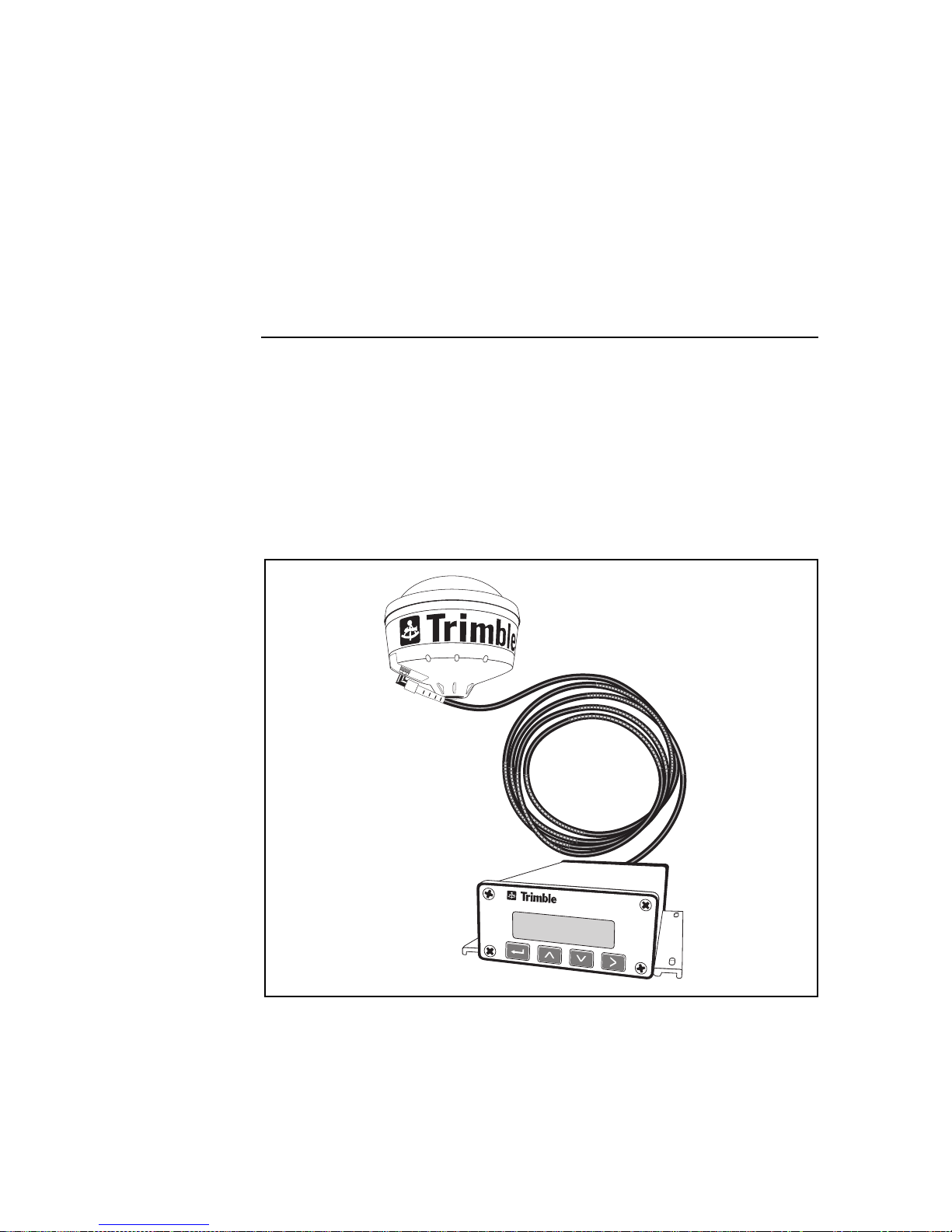
Additionally, the AgGPS 132 receiver (see Figure 1-1) contains
The Choice™ technology, enabling OmniSTA R and Racal LandStar
real-time differential cap abilities.
Figure 1-1
Ag
GPS 124/132 Operation Manual 1-1
GPS Receiver
Ag
Page 26

Overview
1
As a part of a precision agriculture system, the AgGPS receiver
outputs s ubmeter GPS position information to a variety of farming
equipment, including yield monitors, parallel swathi ng guidance
systems, variable rate planters, spray application and soil sampling
controllers, and portable field computers.
The AgGPS receivers output real-time submeter positions and 0.1
mile-per-h our (0.1 6 kph ) v eloci ty acc urac y t hrough NMEA-01 83 and
TSIP (T rimble Standar d Interface Pr otocol) messag es. A 1 PPS (pulse
per second) stro be signal can als o be used to synchr onize time and log
event marker input when using external instruments.
1-2
Ag
GPS 124/132 Operation Manual
Page 27

1 Overview
1.1 Differential GPS Positioning
The AgGPS receivers use differential GPS (DGPS) to achieve
submeter (<3.28 ft) accuracy. DGPS requires two or more receivers.
One receiver, called the reference or base station, is located at a
known point to determine the GPS measurement errors. An unlimited
number of mobile AgGPS receivers, sometimes called rovers, collect
data at unknown locations within the transmission range of the
reference station. The reference station broadcasts correction values,
which are a pplied to the AgGPS receiver posi tion. Errors common at
both the reference and rover receivers are corrected.
1.1.1 Sources of GPS Error
The largest source of GPS position error is Sel ective Availability
(S/A). S/A is induced by the U.S. government for the purpose of
restricting full GPS accuracy to all except authorized users. The
magnitude of S/A combined with other error sources results in
autonomous (single receiver) horizontal accuracies of up to 100
meters (328 feet). If the U.S. government turns S/A off, autonomous
GPS horizontal accuracy would be about 10 meters (32.8 feet).
Atmospheric conditions (especially in the ionosphere), multipath
(GPS signals bouncing off objects before reaching the antenna), and
receiver (electronic) noise are in large part responsible for the
remaining 10 meters (32.8 feet) of error.
DGPS removes most of the erro rs cause d by S/A and t he atmosphe re.
The AgGPS receivers use the latest advancements in receiver design
to minimize th ese errors. For more information about S/A,
atmospheric ef fe cts, and o ther sourc ed of error, revie w
tutorials found on the Trimble web site (
Ag
GPS 124/132 Operation Manual 1-3
WWW.TRIMBLE.COM
All About GPS
).
Page 28

Overview
1.1.2 DGPS Accuracy
Accuracy of the AgGPS receiver wit h differential correction is better
than 1 meter RMS (3.2 feet) + 10 ppm times the distance between the
reference station and the mobile receiver given the following
conditions:
1
•
•
•
•
•
•
Number of satellites used: > 5
PDOP: < 4
Signal to Noise Ratio: > 6
Satellite Elevation Mask: > 7.5
Low multipath environment
RTCM-compatible corrections broadcast from a Trimble
4000RSi or equivalent
Number of visible satellites
Four or more satellites must be visible to calculate a threedimensional position (latitude and longitude, altitude, and time).
Three or more satellites must be visible to calculate a twodimensional position (latitude and longitude, and time). One or more
satellites must be visible to compute a zero-dimensional (time only)
position. Three-dimensional positions are most accurate. On the
GPS receiver you can set configurations to determine how many
Ag
satellites are used to compute GPS positions.
1-4
Ag
GPS 124/132 Operation Manual
Page 29

1 Overview
Position Dilution of Precision (PDOP)
PDOP is a unitless meas ure indicating when the satellite geometry
can provide the most accurate results. When satellites are spread
around the sky, the PDOP value is low and the computed position is
most accurate. When the satellites are grouped closely together, the
PDOP is high and positions are less accura te. You can configure a
PDOP Mask to control the point at which the AgGPS receiver stops
outputting posit ion reports . For submet er accurac y , the PDOP must be
4 or less.
In some agricult ural a pplic ation s, a PDOP Mas k of 12 or more can be
used to prevent loss of data. However, accuracy can suffer as PDOP
rises. There is a trade-off between optimal GPS accuracy and
continuous operation.
Signal-to-Noise Ratio
Signal-to-Noise Ratio (SNR) is a measure of the satellite signal
strength. Accuracy improves as the signal strength increases. More
signal with less noise equals better accuracy. To compute positions
with strong signals, the SNR mask should be set to the default, 6 or
more.
Elevation Mask
When a satellite is low on the horizon, the GPS signals must travel a
great distance through the atmosphere, delaying reception by the
GPS receiver. You can minimize noisy data by adjusting (tuning)
Ag
the Elevation Mask. Satellites below the mask are excluded from the
position computat ion . The re commended setting for highest accuracy
is 8°. There i s a tra de-of f bet ween ac curac y and cont inuous operati on;
lowering the mask ensures continuous operation.
Ag
GPS 124/132 Operation Manual 1-5
Page 30

Overview
Multipath
GPS signals are sometimes reflected off nearby objects, particularly
metallic objects , creating fa lse or erron eous results . This phenomenon
is known as multipath. Severe multipath can induce errors of many
meters, while mild multipath may cause small, undetectabl e errors.
Optimal accuracy is obtained by collecting data in an environment
that is devoid of large reflective surfaces, like buildings and trees. The
GPS receiver Everest™ multipath reduction option helps reduce
Ag
the effects of multipath.
Base station receiver
GPS receiver differential position accuracy is dependent upon the
Ag
differen tial correcti on quality supplied in t he RTCM SC-104 message
format.
1
1-6
Ag
GPS 124/132 Operation Manual
Page 31

1 Overview
1.2 Measuring GPS Accuracy
To measure GPS accuracy you must have some knowledge of
coordinates and datums. When comparing geographic data obtained
from different sources, the data must be referenced to the same datum
and coordinate system. Different datums and coordinate systems
provide different coordinate values for any geographic location.
In North America, for example, two different datums, NAD 27 and
NAD 83, a re co mmon ly used. A particular place on the surface of the
earth has different latitude and longitude coordinates in each datum.
The AgGPS receivers provide coordinates in the NAD 83 datum.
Existing background maps for the N AD 27 datum do no t reg ister with
GPS data based on the NAD 83 datum.
*
Note – The North American Datum 1983 (NAD 83) is, for all practical
purposes, equivalent to WGS-84 (World Geodetic Survey 1984). GPS
data is referenced to the WGS-84 datum.
1.2.1 Receiving Beacon DGPS
To utilize free radiobeac on differential signals, the AgGPS receivers
use dual-channel, fully-automatic beacon receiver electronics for
tracking broadcasts conforming to the IALA Standard. The default
configurat ion when using beacon DGPS al lows t he AgGPS receiv er to
determine the ten most powerful radiobeacons in your vicinity. The
closest beacon is used. Both Beacon channels are configured to
search and track the two nearest radiobeacons in the database.
The receiver can also be configured to search for user-defined station
frequencies. The EZ beacon feature enables easy local beacon
selection.
Ag
GPS 124/132 Operation Manual 1-7
Page 32

Overview
1
The AgGPS receivers continuously monitor the integrity of the da ta
received from the differential radiobeacon(s). If excessive errors in
the data stream are found, the receiver automatically switches to a
different radiobeacon, if one is available.
Radiobeacon signals propagate through ground and sky waves. Hilly
and mountainous terrains generally do not affect the beacon
reception. Near the bea con transmi tter the signal can be recei v ed e v en
in canyons. Canopy has no effect on signal reception.
Beacon signals ar e greatly ef fecte d by nat ural and human-made noise.
Lightning, automobile ignition, electric motor, and high voltage
power lines can be a severe source of noise. In addition, during night
hours at longer distances from the beacon station (240 to 480 Km or
150 to 300 mi), the sky wave (reflected off the ionosphere) can
interfere with the ground wave beacon signal. This self-jamming at
night may be a problem with stronger beacon stations. Integrity
monitoring of the beacon frequency can be performed with the
optional TSIP Talker software.
*
Note – A phenomenon called geographic de-correlation, causes
radiobeacon signals to become less accurate as the distance from
the base station increases. The amount of beacon accuracy
degradation depends on the ionosphere and the amount of Selective
Availability. Degradation can be as much as 1 meter (3 feet) for every
100 km (60 miles).
1-8
Ag
GPS 124/132 Operation Manual
Page 33

1 Overview
1.2.2 Receiving Satellite DGPS (AgGPS 132 only)
Satellite differential GPS signals are sent from a ground station
through a satellite transponder to users within view of the satellite.
The corrections are sent in a format that allows the construction of a
local differential correction applicable to the entire coverage region.
The AgGPS receiver contains both OmniSTAR and Racal-LandStar
satellite differential technology. To enable satellite differential
capabilities, contact either supplier. Depending on which supplier is
involved, the receiver can be activated by an on-the-air signal or an
encrypted activation message entered on the receiver front pa nel.
Satellite differential signals provide valid corrections over a large
area, but are decoded to provide an accurate correction applicable to
any location within the satellite view area. This is accomplished by
special software algorithms for generating wide area differential
corrections. These algorithms, call ed V irtual Referenc e Station (VRS)
and Virtual Base Station (VBS), depending on the vendor, compute
differential corrections that a base station would generate if it were at
the recei ver 's locati on. This c orrecti on is constan tly update d, so as the
receiver moves around, the correction remains at full accuracy.
Satellite differential signals are line-of-sight and can be blocked by a
mountain, hill, or tree ca nopy. Wet canopy, from a heavy rai n, reduces
the signals even more. The same local environmental factors, like
radar and microwave transmitters, that affect the GPS signals can
interfere with the satellite signals. Power lines usually have no effect.
For specific information about the providers, visit
WWW.OMNISTAR.COM
WWW.RACAL-LANDSTAR.COM
or
on the World Wide Web.
Ag
GPS 124/132 Operation Manual 1-9
Page 34

Overview
1.3 Standard Features
The standard AgGPS 124 and 132 system provides the following:
1
•
•
12 GPS (C/A-code) tracking channels, carrier-phase filtering
Submeter differential accuracy (RMS): assumes at least 5
satellites and PDOP less than 4
•
•
•
•
•
Combined GPS/DGPS antenna
Magnetic antenna mount
5-meter ruggedized an tenna cable
Data/Power ca ble
LCD display with four-button keypad to configure and view
system properties
•
Two RS-232 serial and CAN-rea dy ports:
•
NMEA-0183 output: ALM, GGA, GLL, GSA, GSV,
MMS, RMC, VTG, ZDA (The de fault NMEA messages
are GGA, GSA, and VTG)
•
RTCM SC-104 input and output
•
TSIP input and output
1-10
•
Outputs 1 PPS (pulse per second) strobe signal on either
serial port, allowing an external instrument to
synchronize its internal time with the AgGPS clock
oscillator.
Ag
GPS 124/132 Operation Manual
Page 35

1 Overview
1.4 Receiver Enhancements
GPS systems contain several purchase options designed to
Ag
maximize receiver performance. Depending on the system you
ordered, the following options may or may not be included.
1.4.1 Fast Rate (P/N 33176-10)
The Fast Rate option enables the AgGPS receiver to output position
data up to 10 times per second. Fast Rate output is important in
parallel swathing and variable rate applications. (A 5 Hz Fast Rate
option is included with the Parallel Swathing Option.)
1.4.2 Differential Base Station (P/N 33176-30)
The Differential Base Station option enables the AgGPS receiver to
output RTCM differential corrections. With a radio link, these
corrections can be broadcast and used by other DGPS receivers.
1.4.3 Everest Technology (P/N 33176-40)
The Everest™ mult ipath reduction option improves DGPS receiver
accuracy by filtering reflected GPS signals before they are processed
by the DGPS receiver. Everest technology provides maximum
accuracy near trees, buildings, and reflective surfaces.
(The Everest multipath reduction option is included with the
Parallel Swathing Option.)
Ag
GPS 124/132 Operation Manual 1-11
Page 36

Overview
1.5 Application Options
The AgGPS system contains several purchase options that increase
the number of applicati ons for which the AgGPS receivers can be
used.
1.5.1 Parallel Swathing (P/N 34623)
The AgGPS Parallel Swathing option enhances the AgGPS receiver
with an easy-to-use, plug-and-play lightbar. The lightbar indicates
off-track error, which the operator uses to steer back on-line.
The AgGPS Parallel Swathing Option helps reduce farm ex penses by
minimizing redundant applications and skipped areas. Efficient field
coverage enables maximum ground coverage in the shortest possible
time.
Independent data ports enable the AgGPS receiver to simultaneously
operate the lightbar and output data to a variable rate controller or
other device.
1
1.5.2 Ag Field Pack (P/N 32294)
The Ag Field P ac k include s the l umbar pack, a ntenna pole s, bat teri es,
and cables to keep hands free when operating the AgGPS receiver on
foot. The Field Pack is ideal for crop scouting and field mapping
applications.
1-12
Ag
GPS 124/132 Operation Manual
Page 37

1 Overview
1.6 Receiver Connections
Figure 1-2 shows the AgGPS receiver back panel and its associated
ports.
Figure 1-2 Back Panel
Both Port A and Port B can accept power. The standard power/data
cable (P/N 30945) supplies power.
Ag
GPS 124/132 Operation Manual 1-13
Page 38

Overview
1.6.1 ASCII, TSIP, and RTCM Input
Both Port A and Port B are used to input ASCII, TSIP, RTCM, and
CAN data from an external device. ASCII data ca n be received from
an external sensor, converted into a NMEA message, and exported to
another device. TSIP command packets are used to set and monitor
GPS and Beacon parameters from the optional TSIP Talker software.
RTCM data can be input from an external source such as an FM
pager.
1.6.2 RTCM, TSIP and NMEA Output
Both Port A and Port B are used to out put RTCM, TSIP, NMEA 0183
or CAN messages to an interface device. RTCM is output when
operating in base mode. TSIP is output whe n communicati ng with th e
optional TSIP Talker software. NMEA is output when expo rting GPS
position information to an external device, such as a yield monitor.
CAN is used when operating a CAN bus.
1
1.6.3 1 PPS Output
Either port can output a 1 PPS (pulse per second) strobe signal to
synchronize the external instruments to the receiver's internal clock.
1-14
Ag
GPS 124/132 Operation Manual
Page 39

2 Installing the
Ag
This chapter shows you how to:
•
•
W e reco mmend you read th is chapter before attemp ting to insta ll your
Ag
unpack and inspect the shipment
install the following:
•
•
•
GPS receiver.
GPS Receiver
GPS receiver
Ag
antenna
interface devices
2.1 Unpacking and Inspecting the Shipment
Inspect the shipping cartons for any signs of damage or mishandling
before unpacking the receiver.
Report any damage to the shipping carrier immediately.
Ag
GPS 124/132 Operation Manual 2-1
Page 40

Installing the AgGP S Rec eiver
2.1.1 Opening the Shipping Carton
The shipment could include one or more cartons, depending on the
number of optional accessories ordered. Open the shipping cartons
and make sure that all of the components indicated in Tables 2-1
through 2-3 are included.
2
Table 2-1
Qty P/N Description
1 33302-01
1 33580-00
Table 2-2
Qty P/N Description
1 33606-00 AgGPS 124 Receiver
1 29635-50 AgGPS 124 Antenna
GPS 132 Only Components
Ag
Ag
GPS 132 Receiver
Ag
GPS Antenna
GPS 124 Only Components
Ag
Table 2-3 AgGPS Receiver Components
Qty P/N Description
1 12920-00 Magnetic Mount for Antenna
1 32608 5-meter (16-foot) Ruggedized Antenna Cable
1 30945 Data/Power Cable
1 33301-00
Ag
GPS 124/132 Operation Manual
1 11093 Coax Tape Seal
1 25110-00 Warranty Activation Card
2-2
Ag
GPS 124/132 Operation Manual
Page 41

2 Installing the AgGPS Rece iver
As shown in Table 2-4, the bill of lading could list one or more of the
following factory installed enhancements.
Table 2-4
Qty P/N Description
1 33176-10 Fast rate capability
1 33176-30 DGPS Base capability
1 33176-40 Everest multipath reduction technology
GPS Receiver Enhancements
Ag
As shown in Table 2-5, the bill of lading could list one or more of the
follo wing opt ions.
Table 2-5
Qty P/N Description
1 32294-00 Ag Field Pack 120 volts
1 32294-10 Ag Field Pack 240 volts
1 34623-00 Parallel Swathing
GPS Application Options
Ag
Ag
GPS 124/132 Operation Manual 2-3
Page 42

Installing the AgGP S Rec eiver
The bill of lading could include one or more of the items listed in
Table 2-6 if optional components or accessories are ordered.
Table 2-6 Optional Components
Qty P/N Description
1 29510 10-meter (32-foot) Antenna Cable
1 30660 Ag Leader Power/Data Cable
1 30700 3.6-meter (12-foot) Extension Data Cable
1 32015 Power/Data Cable RTCM/NMEA
1 32609 CASE AFS Power/Data Cable
1 34189 John Deere GreenStar Data Cable
1 35142 RDS Cable
1 38112 Receiver ceiling mounting bracket
1 30661 Windows CE Cable with Power Leads
2
DE9-M to DE9-F
1 35283 Windows CE Cable with Cigarette Power
Adapter
2.1.2 Repor ting Shipping Problems
Report any problems discovered after you unpack the shippi ng
cartons to both Trimble Customer Support and the shipping carrier.
2-4
Ag
GPS 124/132 Operation Manual
Page 43

2 Installing the AgGPS Rece iver
2.2 Ins tall a tion Guidelines
GPS receivers are designed to be mounted on a flat surface in any
Ag
orientation. The bottom of the receiver has mounting flanges for
securing to a flat surface with screws. For ceiling mounts, ask your
local dealer about Trimble’s ceiling mounting bracket.
2.2.1 Choosing a Location
The AgGPS receiv er can be installed in any convenient location c los e
to the external device. The location you choose should:
•
•
•
allow visibility of the front panel
provide clearance for the antenna and interface connections
be within 3.6 meters (12 feet) of the external instrument port
(The optional 3.6-meter (12-foot) extension cable can
be used.)
2.2.2 Considering Environmental Conditions
Although the AgGPS receiv er is located within a waterproof housing,
it should be installed in a dry location. Avoid exposure to extreme
environmental conditions, including:
•
•
•
•
•
water
excessive heat (> 65°C or 149°F)
excessive cold (< -20°C or -4°F)
high vibration
corrosive fluids and gases
Avoiding these conditions improves the receiver’s performance and
long-term product reliability.
Ag
GPS 124/132 Operation Manual 2-5
Page 44

Installing the AgGP S Rec eiver
2.3 Mounting the Receiver
To mount the receiver:
1. Drill four holes in the mounting surface using the slotted
holes in the mounting brackets as a template.
2
*
Note – If machine screws are used, tap the mounting holes to fasten
the receiver to the mounting surface. Use 8-32 socket head cap
screws to fasten the receiver to the mounting surface. Alternatively,
use self-tapping screws to secure the receiver.
2. Use screws to secure the brackets to the mounting surface.
2.4 Moun ting the Antenna
Choose a location for the antenna that is safe from damage during
normal operation. The ant enna can be mounted to a flat su rface using
the magnetic mount. Use the following guidelines when selecting a
location:
•
•
Place the anten na on a f lat su rf ace along t he c enter line of the
vehicle.
Choose an area with clear view to the sky above metallic
objects. The top of a mast or pole is recommended.
•
•
•
Caution – A grain tank extension may block low elevation satellites.
I
2-6
Do not mount the antenna close to stays, electrical cables,
metal masts, and other antennas.
Do not mount the antenna near transmitting antennas, radar
arrays, or satellite communication equipment.
Avoid areas with high vibration, excessive heat, electrical
interference, and strong magnetic fields.
Ag
GPS 124/132 Operation Manual
Page 45

2 Installing the AgGPS Rece iver
2.4.1 Sources of Electrical Interference
Several sources of electrical and magnetic noise are:
*
•
•
•
•
•
•
•
•
Note – You can check the antenna installation for locally generated
noise by connecting a PC to the receiver and running the optional
TSIP Talker program. If you observe interference, move the antenna
to a different location. Raising the antenna several decimeters may
minimize the noise. TSIP Talker can be downloaded from Trimble’s
FTP site: ftp.trimble.com.
gasoline engines (spark plugs)
televisions and PC monitors
alternators and generators
electric motors
propeller shafts
equipment with DC-to-AC converters
florescent lights
switching power supplies
Ag
GPS 124/132 Operation Manual 2-7
Page 46

Installing the AgGP S Rec eiver
2.5 Routing and Connecting the Antenna Cable
A 5-meter (16.5-foot) antenna cable is included with your AgGPS
receiver (see Figure 2-1). One end of the antenna cable feat ures a
90-degree connector. The opposite end features a straight connector.
Connect the 90-degree connector to the antenna, then route the cable
to the receiver.
2
Figure 2-1 Antenna Cable Connections
2-8
Ag
GPS 124/132 Operation Manual
Page 47

2 Installing the AgGPS Rece iver
When routing the antenna cable, avoid the following hazards:
F
•
•
•
•
•
•
After routing the cable, connect it to the AgGPS receiver. Use
tie-wraps to s ecure the ca ble at several poin ts along th e route. One
tie-wrap is required to secure the cable near the base of the antenna.
This provides strain relief for the antenna cable connection.
When the cable is secured, coil any slack. Secure the coil with a
tie-wrap and tuck it in a safe place.
Tip – Use the coax seal tape, provided with the antenna, to seal the
antenna connector at the antenna. The tape prevents water and
moisture from entering the connection.
sharp ends or kinks in the cable
hot surfaces (exhaust manifolds or stacks)
rotating or reciprocating equipment
sharp or abrasive surfaces
door and window jams
corrosive fluids or gases
2.6 Connecting External Devices
After installing the antenna and receiver, connect and route the
interface cables. The receivers can be powered by a vehicl e or a
customer supplied 12-volt switched power source. Once the receiver
is installed and powered on, the front panel LCD screen lights.
The following sections contain installation instructions for different
power/data cables. Depending on the cable(s) you own, complete the
appropriate installation.
Ag
GPS 124/132 Operation Manual 2-9
Page 48

Installing the AgGP S Rec eiver
2.6.1 Connecting the Standard Data/Power Cable
(P/N 30945)
The Standard Data/Power Cable connects the AgGPS receiver to
many types of external devices (see Figure 2-2).
2
DOS Compatible
Figure 2-2 External Device Cable Connections
2-10
Ag
GPS 124/132 Operation Manual
Page 49

2 Installing the AgGPS Rece iver
To connect the AgGPS receiver to an external device:
1. Connect the CONXALL right angle connector to either port
on the AgGPS receiver.
2. Co nnect the 9-pin DE-9 Male connector to the external
device DE-9 Female connector.
3. Connect the power leads to a switched power source.
*
F
Note – The red lead must be connected to the +12 volts and the black
lead to Ground.
4. Coil excess slack and secure the cable.
Tip – Install the optional 3.6-meter (12-foot) Exte nsion Cable
(P/N 30700) to extend the Standard Data/Power Cable (P/N 30945)
to 7.2 meters (24 feet).
Ag
GPS 124/132 Operation Manual 2-11
Page 50

Installing the AgGP S Rec eiver
2.6.2 Connecting the Optional CASE AFS Po wer/Data Cable
(P/N 32609)
The 1-meter (3-foot) CASE AFS Power/Data Cable connects the
GPS receiver to a CASE AFS installation.
Ag
2
Figure 2-3 CASE AFS Power/Data Cable Connection
To connect the AgGPS receiver to a CASE AFS installation:
1. Connect the straight CONXALL connector to Port A on the
2. Connect the 5-pin connector to th e CASE AFS wiring
3. Coil excess slack and secure the cable.
2-12
GPS receiver.
Ag
harness.
Ag
GPS 124/132 Operation Manual
Page 51

2 Installing the AgGPS Rece iver
2.6.3 Connecting the Optional John Deere GreenStar Data
Cable (P/N 341 89 )
The 1-meter (3-foot) John Deere GreenStar Data Cable connects the
GPS receivers to the John Deere GreenStar system
Ag
(see Figure 2-4).
Figure 2-4 GreenStar Data Cable Connection
Before installing the AgGPS receiv er, you
determine if there is a
must
GPS receiver currently attached to the GreenStar System.
•
If there is
a GPS receiver attached to the GreenStar
not
system, proceed with Step 1.
•
If there is a GPS receiver attached to the GreenStar system,
disconnect it from the wiring harness. This is required to
activate the GreenStar RS 232 port. The harness can be
disconnected from the receiver at the antenna located above
the grain tank. When disconnected, proceed with Step 1.
Ag
GPS 124/132 Operation Manual 2-13
Page 52

Installing the AgGP S Rec eiver
To connect the AgGPS-series receiver to the John Deere GreenStar
system:
1. Inside the cab behind the seat, locate the wiring harness that
connects to the GreenStar mapping processor. From this
wiring harness, gently pull the three short wires from the
casing. (They are approximately 10 inches long; orange,
black and blue; and sealed with shrink wrap). You do not use
the blue cable.
2. Connect the orange wire labeled 967 to the Metripack
connector pin. Insert the pin into the Metripack connector
(P/N 12015793) slot A .
3. Connect the black wire labeled 20E to the Metripack
connector pin. Insert the pin into the Metripack connector
(P/N 12015793) slot C .
4. Connect the AgGPS-GreenStar cable (P/N 34189) to the
Metripack connector (P/N 12015793).
2
5. Connect the data/power cable (P/N 30945) to the
AgGPS-GreenStar cable (P/N 34189).
6. Attach the data power cable (P/N 30945) to port A of the
AgGPS receiver.
7. Attach the power leads of the data/power cable (P/N 30945)
to switched power. Connect the red wire to positive and the
black wire to negative.
2-14
Ag
GPS 124/132 Operation Manual
Page 53

2 Installing the AgGPS Rece iver
2.6.4 Connecting the Optional Ag Leader Power/Data Cab le
(P/N 30660)
The 3.6-meter (12-foot) Ag Leader Yield Monitor Cable connects
GPS receivers to an Ag Leader Yield Monitor
Ag
(see Figure 2-5).
MEMORYCARD
NO
DATE/
TIME
AREACOUNT
FLOW
STOP
LIGHT CLOCK
FIELD LOAD
GRAIN MOIST
WET
GRAIN
STOP
SETUP MEM
HEIGHT
#
ROWS
WEIGHT
DRY
SPEED
GRAIN
YES
ROW
SWATH
SPACE
AREA DIS
INST
AVG
YIEL
YIEL
Figure 2-5 Ag Leader Power/Data Cable Connections
To connect the AgGPS receiver to an Ag Leader Yield Monitor:
1. Connect the CONXALL right-angle connector to either port
on the AgGPS receiver.
2. Connect the 9-pin DE-9 Male connector to the data/power
3. Coil excess slack and secure the cable.
Ag
GPS 124/132 Operation Manual 2-15
port on the Ag Leader Yield Monitor.
Page 54

Installing the AgGP S Rec eiver
2
F
Tip – Install the optional 3.6-meter (12-foot) Exte nsion Cable
(P/N 30700) to extend the Ag Leader Yield Monitor Cable to
7.2 meters (24 feet).
2.6.5 Connecting the Optional Power/Data RTCM/NMEA
Cable (P/N 320 15 )
This cable is useful for sharing an AgGPS receiver port with several
devices. One interface device can be connected to each side of the
connector. This cable can also input external RTCM data while
outputting NMEA to an external device (see Figure 2-6).
Figure 2-6 Power/Data RTCM/NMEA Cable Connections
2-16
Ag
GPS 124/132 Operation Manual
Page 55

2 Installing the AgGPS Rece iver
To connect the optional Power/Data RTCM/NMEA cable:
1. Connect the CONXALL right-angle connector to port A on
the AgGPS receiver.
2. Co nnect the 9-pin DE-9 Male connector( s) to the external
device DE-9 Female connector.
3. Connect the power leads to a switched power source.
*
Note – The red lead must be connected to the +12 volts and the black
lead to Ground.
4. Coil excess slack and secure the cable.
2.6.6 Connecting the Optional RDS Cable (P/N 35142)
The 3.6 meter (12 foot) RDS cab le conne ct s an AgGPS receiver to an
RDS Yield Monitor.
To connect the optional RDS cable:
1. Connect the 12-pin CONXALL connector to port A on the
GPS receiver.
Ag
2. Attach the 9-pin RS 232 Connector to the RDS Yield
Monitor.
Ag
GPS 124/132 Operation Manual 2-17
Page 56

Installing the AgGP S Rec eiver
2.6.7 Connecting the Optional Windows CE with Cigarette
Power Adapter Cable (P/N 35283)
The optional Windows CE cable connects an AgGPS receiver to a
Windows CE computer.
To connect the optional Windows CE with Cigarette Adapter cable:
1. Connect the 12-pin CONXALL connector to port A on the
GPS receiver.
Ag
2. Attach the 9-pin RS 232 connector to the Windows CE
computer.
3. Connect the cigarette adapter to the power source.
2.6.8 Connecting the Optional Windows CE Cable
(P/N 30661)
To connect the optional Windows CE cable:
2
1. Connect the 12-pin CONXALL connector to port A on the
GPS receiver.
Ag
2. Attach the 9-pin RS 232 connector to the Windows CE
computer.
3. Connect the power leads to a switched power source.
2-18
Ag
GPS 124/132 Operation Manual
Page 57

3 Getting Started
This chapter shows you how to use the:
•
•
We recommend you read through this chapter to learn basic menu
operations before attempting to use your AgGPS receiver.
keypad on the front panel
screen
Home
3.1 Using the Front Panel
After powering on the receiver, the front panel displays the
screen. From the
receiver screens. Figure 3-1 displays the screen organization.
Chapters 3, 4, 5 and 6 explain each screen in detail.
Home
screen, press 2 or 3 to access other
Home
Ag
GPS 124/132 Operation Manual 3-1
Page 58

Configuration
GPS 124/132 Operation Manual
Ag
Getting Started 3
Status
Home Operations
Guidance
Utility
RCVR CAN
DGPS
GPS
DGPS Port A Port B Can A Can B
GPS
Guidance
LightBar
GPS Screen Hierarchy
Ag
3-2
Figure 3-1
Page 59

3 Getting Started
3.1.1 Viewing Status Screens
Figure 3-2 shows the keypad and the four keys that navigate through
the AgGPS menu hierarchy.
LCD Display
Figure 3-2
Enter K ey
Up Arrow Key
GPS 124 and 132 Receiver Front P anel
Ag
Right Arrow Key
Down Arrow Key
Ag
GPS 124/132 Operation Manual 3-3
Page 60

Getting Started
3
Table 3-1 describes the actions performed by the keys.
Table 3-1 Keypad Actions
Key Description
4
1
2
3
1
+
2 Mo v es back one level in screen hierarchy. Ultimately, it
Performs several actions:
•Press
a screen. When options are available, the
symbol appears in the upper right-hand corner of
the screen.
•Press
(AgGPS 132 only)
Cycles through the available screens.
Cycles through the available screens.
Moves through the main menu screens.
returns you to the
• When in a view screen described in this chapter,
returns you to the
• When in a configuration screen described in
Chapter 6, Configuring the AgGPS 124 and 132
Receiver, returns you to the main menu
configuration screen. Press again to return to the
Home
4 to cycle through the options displayed on
4 and hold to change DGPS mode.
Home
screen.
screen.
Home
screen.
4
3-4
Ag
GPS 124/132 Operation Manual
Page 61

3 Getting Started
Contrast
Language
Home
Operations
Status
Config
Display
Options
Units
Display
Lock
3.2 The Home Screen
The
Home
line of the
screen is just the first option in the main menu. The top
Home
screen displays import ant GPS status indicat ors. The
bottom line displays important DGPS indicators.
Figure 3-3 shows the
Home
screen and following screens.
Figure 3-3 Home Screen Hierarch y
Ag
GPS 124/132 Operation Manual 3-5
Page 62

Getting Started
3.2.1 Beacon and Satellite Mode Home Screens
3
*
F
Note – Reference to Satellite DGPS applies only to the AgGPS 132.
Tip – When in Beacon mode, a B, Beacon Searching, Beacon
Tracking
corner of the screen. To change modes, press
seconds. To display satellite differential information, press
S appears in the lower-left corner of the screen.
When beacon information appears in the
receiver operates in Beacon mode. When satellite DGPS information
appears in the
Satellite Differential mode. The DGPS source conf i gurat ion se tting is
changed.
The following is a sample
4
, or Beacon FFT message appears in the lower left
4 and hold for 5
screen, the AgGPS
Home
screen, the AgGPS 132 receiver operates in
Home
Home
screen with Beacon DGPS:
4 until an
3-6
The following is a sample
(AgGPS 132 only):
Home
screen with Satellite DGPS
Ag
GPS 124/132 Operation Manual
Page 63

3 Getting Started
Figure 3-4 explains the GPS status indicators.
Current PDOP value
(see Position Diluti on of
Precision (PDOP), page 1-5).
Number of GPS satellites (SVs) used in
the position fix.
Type of position recorded (see Table 3-2).
Figure 3-4 GPS Status
Table 3-2 Position Types
*
Display Description
SRCH Searching for satellites.
TRCK Tracking satellites.
G/2D Outputting 2-dimensional autonomous positions.
G/3D Outputting 3-dimensional autonomous positions.
D/2D Outputting 2-dimensional differential positions.
D/3D Outputting 3-dimensional differential positions.
Ant? No antenna connected to receiver.
Note – The / symbol spins when the receiver is operating properly.
When the / symbol is still, an error occurred.
Ag
GPS 124/132 Operation Manual 3-7
Page 64

Getting Started
3
Figure 3-5 explains the beacon DGPS status indicators.
The beacon signal-to-noise ratio.
S/N values range from 0 to 30.
High numbers are best. Above 6
is acceptable.
The beacon frequency. Frequency varies
depending upon the beacon used.
The beacon operating mode.
Indicates the receiver is operating in Auto Select mode.
Indicates the receiver is using beacon DGPS.
Figure 3-5 Beacon DGPS Status
3-8
Ag
GPS 124/132 Operation Manual
Page 65

3 Getting Started
Table 3-3 describes the options available in Beacon operating mode.
Table 3-3 Options in Beacon Operating Mode
Value Description
B Operating in beacon mode.
Beacon Searching Searching for beacon signals.
Beacon Tracking The receiver is tracking beacon signals and
is attempting to gain lock.
Ag
Beacon Idle The
GPS beacon receiver is not active.
Beacon FFT The
Beacon Disabled Beacon DGPS is disabled. Check
External RTCM Differential corrections are provided by an
Battery is Low Warning replaces DGPS information when
Ag
GPS receiver is looking for a beacon
across the signal spectrum.
configuration settings to enable beacon
DGPS.
external source through port A or B.
battery voltages are low.
Figure 3-6 explains the satellite DGPS status indicators.
(AgGPS 132 only)
Signal-to-Noise Ratio of DGPS
signal, see Table 3-3.
Figure 3-6 Satellite DGPS Status
Ag
GPS 124/132 Operation Manual 3-9
Frequency for tracked D GPS satellite.
Frequencies vary depending on your
locatio n and DGPS service provid er.
Indicates receiver is using Satellite DGPS.
Page 66

Getting Started
3
Table 3-4 explains signal-to-noise ratio values.
Table 3-4 DGPS Signal-to-Noise Values
Va lue Description
Below 4 Unusable
4–8 Fair
>8 Excelle n t
Table 3-5 shows the possible satellite differential mode indicators.
Table 3-5 Satellite Differential Mode Status Indica tors
Indicator Description
S ####.### S/N ## Operating in Satellite Differential mode.
S SRCH ###.## Searching for Satellite Differential signal.
S TRCK ####.## Tracking satellite without acquiring
signal lock.
3-10
Ag
GPS 124/132 Operation Manual
Page 67

3 Getting Started
3.3 Below Home Screen Configurables
The
Contrast, Units, Configuration Lockout
are found under the
1. Display the
2. Press 2 to view the
!"#$% " !
!!
3. Press 2.
3.3.1 Contrast
As lighting conditions change, the LCD display could become
diff icult to read. To decrease the contrast, enter a low number . Hi gher
numbers increase screen contrast.
' '$!
2
&
Home
Home
and
Language
screen. To display these screens:
screen.
Display Options
screen.
settings
To change the contrast:
1. Press 3.
2. Press 1 to lighte n the contra st.
3. Press 2 to darken the contrast.
Ag
GPS 124/132 Operation Manual 3-11
Page 68

Getting Started
3.3.2 Units
3
The
screen enables the rec eiver to display either U.S. or Metr ic
Units
units. This setting does not affect data output.
' ( !
)
To change the units:
1. Press 3.
2. Press 2 to select the appropriate units.
3. Press 4 to save.
3-12
Ag
GPS 124/132 Operation Manual
Page 69

3 Getting Started
3.3.3 Configuration Lockout Screen
The
Configuration Lockout
screen provides protection against
tampering. To make the configuration screens invisible, input the last
five digits of the receiver serial number. To view the configuration
screens again, input the five-digit number a second time.
& $!!+*
To en ter the password:
1. Press
2. Press 2 or
to enter the Lock Display screen.
4
to input the values.
1
3. Press 3 to input the next number.
4. Continue until complete.
5. Press 4 to accept.
When complete,
$# * $!!+*
appears. The configuration
screens are not visible. Repeat the procedure above to unlock the
configuration screens.
Ag
GPS 124/132 Operation Manual 3-13
Page 70

Getting Started
3.3.4 Language Screen
3
The
Language
screen provides the ability to di splay English, German,
French, Portuguese, and Spanish on the front panel.
' ,$-.$-
&-# !/
To change the display language:
1. Press 3.
2. Press 2 or
to select the desired language.
1
3. Press 4.
The screen automatically displays the configured language.
3-14
Ag
GPS 124/132 Operation Manual
Page 71

4 Operation Screens
Home
Operations
Status
Configuration
Perimeter
Area
Adjusted
Area
Guidance
Line
Length
Utility
See the
AgGPS Parallel Swathing
Option Manual
Screens visible only when
LBAR is configured as
a Port input and output
This chapter shows you how to:
•
•
use the Guidance Operation screens
use the Utility screens
Tri mble recommends that you rea d t hrough t his c hapt er t o lear n basi c
skills before at tempting to calculate field area and measure line
lengths. Figure 4-1 maps the operation screens.
Ag
GPS 124/132 Operation Manual 4-1
Figure 4-1 Operation Screen Hierarchy
Page 72

Operation Screens
4.1 Utility Screens
4
To view the Utility screens, press 3 from the
Operations
screen appears. Press 2. Press 3 until the
appears.
( # % !
!!
2
&
Home
screen until the
Utility
screen
4-2
Ag
GPS 124/132 Operation Manual
Page 73

4 Operation Screens
4.1.1 Area Calculation
Figure 4-2 explains the following
4
$ 0
! **
4
$ 0
The accumulated area in hectares. An A
appears when shown in acres. Hectares
are displayed when the units are metric.
Acres are shown when the units are in
U.S. Standard. (To change units, refer to
Section 3.3.2, Units.)
Press 4 to Add, Delete, or Clear area points.
! **
Area Calculation
screen.
Indicates that pressing 4 adds an area
point. See Table 3-6.
The total number of area points.
Figure 4-2 Area Calculation Screen
Ag
GPS 124/132 Operation Manual 4-3
Page 74

Operation Screens
Table 4-1 describes the Area Calculation functions.
Table 4-1 Area Calculation Functions
To change the Delete/Add/Clear function:
4
Value Description
Add Adds area points
Del Deletes last area points
CLR Clears all area points.
Use before beginning a new field.
1. Press 3.
The cursor flashes.
2. Press
3. Press 4 to accept the change.
4.1.2 Adjusted Area
The
Adjusted Are a
width setting in the
(See
AgGPS Parallel Swathing Option Manual
*1.!* $
0$
*
Note – The
AgGPS Parallel Swathing Option.
When using the pa rallel s wathing option, obtain an accurat e fi eld area
by driving the field perimeter. Place the end of the applicator boom
over the field boundary. Entered area points are offset to the Boom
end. The resulting area is displayed here, in the
or 1 until the option you desire is visible.
2
screen displays an area offset by 1/2 the swath
Guidance Configuration
menu.
.)
Adjusted Area
screen is only used when operating the
Adjusted Area
screen.
4-4
Ag
GPS 124/132 Operation Manual
Page 75

4 Operation Screens
4.1.3 Path Length
The
Path Length
area points.
$/ ,-/
2!
As area points are added, the path length increases.
4.1.4 Perimeter
The
Perimeter
line between the last and first entered area point is used to close the
area.
2
2!
screen displays the length traveled between entered
screen displays t he perimeter of entered area points. A
As area points are added, the perimeter increases.
4.1.5 Segment Length
The
Segme nt Lengt h
entered area points.
-2 ,-/
2!
As area points are added, the last segment length is calculated.
Ag
GPS 124/132 Operation Manual 4-5
screen displays the length between the last two
Page 76

Operation Screens
4
4-6
Ag
GPS 124/132 Operation Manual
Page 77

5Status
This chapter shows you how to use the GPS, DGPS, Receiver, and
CAN status screens.
Trimble recommends that you read through this chapter when
troubleshooting and verifying the status of the AgGPS receiver.
Ag
GPS 124/132 Operation Manual 5-1
Page 78

Status
5
Figure 5-1 maps the AgGPS status screens.
Home
GPS
Position
Altitude
Velocity
Satellite
Info
DOPs
Operations
Beacon
Status
Alternate
Beacon
Data
Source
DGPS
Age
DGPS
(132 only)
Satellite
Status
Service
Provider
Data
Source
DGPS
Age
Racal-LandStar
Info
OmniSTAR
Info
Service
ID
Status
Receiver
Time
Date
Serial #
Version
Receiver
Options
System
Voltage
Incident
Report
Configuration
CAN
Channel
A
Channel
B
Figure 5-1 Status Screen Hierarchy
To view the status screens, press 3 from the
Status
5-2
screen appears. Press 2.
Home
Ag
GPS 124/132 Operation Manual
screen until the
Page 79

5 Status
5.1 GPS Status Screens
To view the st atu s of the GPS information, press 3 until
appears. Press 2 to view the available screens.
!
2
!!
&
GPS Status
Ag
GPS 124/132 Operation Manual 5-3
Page 80

Status
5.1.1 Location
5
Figure 5-2 explains the following
345
3 56
345
Latitude
Type of position recorded. See Table 5-1.
356
Longitude
Shows the position dimensions. See Table 5-2.
Location
screen.
5-4
Figure 5-2 Location
Table 5-1 Types of Recor ded Positions
Value Description
D Differential GPS
S Searching for DGPS satellites. Current position is old.
G Au tono mous GPS
- No valid satellites are tracked.
Table 5-2 Position Dimensions
Value Description
2 Two-dimensional position
3 Three-dimensional position
Ag
GPS 124/132 Operation Manual
Page 81

5 Status
5.1.2 Altitude
Figure 5-3 explains the following
# .* ),
2
# .* ),
2
Current GPS antenna altitude in Mean Sea
Leve l (MSL). The display is updated every
second or when new information becomes
available.
Figure 5-3 Altitude
Altitude
screen.
Ag
GPS 124/132 Operation Manual 5-5
Page 82

Status
5.1.3 Velocity
5
Figure 5-4 explains the following
"* )0
0*- 73
"* )0
Horizonta l velocity in miles per
hour.
0*- 73
Heading in degrees from North,
see Table 5-3.
Figure 5-4 Velocity
Velocity
screen.
5-6
Table 5-3 Heading Values
Value Description
0° North
90° East
180° South
270° West
Ag
GPS 124/132 Operation Manual
Page 83

5 Status
5.1.4 GPS Satellite Information
Figure 5-5 explains the following
4
'/ &# 82
494
4
'/ &# 82
494
Satellite elevation above horizon.
GPS satellite signal-to-noise ratio in
AMUs. S/N values ra nge from 0 to 35.
Under a canopy, values greater than 6
are acceptable. In low multipath areas,
such as an open field with no canopy,
S/N values greater than 2 are acceptable.
The higher the number the better.
GPS Satellite Informa tion
Satellite azimuth.
screen.
Press 4 to cycle through all 12 channels.
Figure 5-5 GPS Satellite Information
Ag
GPS 124/132 Operation Manual 5-7
Satellite number or ID .
GPS receive r channel . There are 12 channel s. and
each channel is dedicated to tracking an available
satellite.
Indicates DGPS data for this satellite has been recorded.
Page 84

Status
5
A channel may contain incomplete satellite information.
Table 5-4 explains the messages that could appear on the screen.
Table 5-4 Incomplete Satellite Data Messages
Ch Sv S/N El Azm Meaning
1 17 35 -- -- No data yet received from the satellite.
1 17 Searching Searching for but not tracking satellite.
1 Idle No satellite available to track.
5-8
Ag
GPS 124/132 Operation Manual
Page 85

5 Status
5.1.5 DOPs
Figure 5-6 explains the following
! 0 4
9 :
! 0 4
Horizontal Dilution of Precision
(HDOP). HDOP indicates the
quality of the horizontal GPS
position.
Position Dilution of Precision (PDOP).
PDOP indicates the three-dimensional
quality of the GPS solution.
9 :
DOPs
screen.
Time Diluti on of Precision
(TDOP). TDOP indicates the
quality of the time measurement.
Vertical Dilution of Precision (VDOP).
VDOP indicates the quality of the vertical
position.
Figure 5-6 DOPs
When viewing DOP information, lower numbers are better. For a
description see Position Dilution of Precision (PDOP), page 1-5.
Press 2 to return to the main m enu.
Ag
GPS 124/132 Operation Manual 5-9
Page 86

Status
5.2 Beacon DGPS Status (Beacon Mode Only)
5
*
Note – If using an AgGPS 132, press
becomes visible. Press and hold
corner. This ensures you are in beacon mode.
To view the stat us of the DGPS in formati on, press 2 from the
screen. Press 3 until
through each screen.
!
!!
2
&
DGPS Status
1 + 2
4
until B appears in lower left
appears. Press 2 to move
until the
Home
screen
Status
5-10
Ag
GPS 124/132 Operation Manual
Page 87

5 Status
5.2.1 Beacon Status
Figure 5-7 explains the following
4
$ ;08
4 *.
4
$ ;08
Beacon frequency.
Beacon frequency varies
depending on the beacon.
Press to scroll through the Beacon name in use and
the distance from the last recorded position.
4 *.
Beacon signal strength measured at
receiver antenn a.
Beacon Status
screen.
Beacon signal-to-noise ratio.
Figure 5-7 Beacon Status
*
Ag
GPS 124/132 Operation Manual 5-11
Note – When searching for a beacon signal, the bottom line display
switches between
Searching, and Disabled Messages.
Idle, Wideband FFT, Tracking,
Page 88

Status
5.2.2 Alternate Beacon
5
Figure 5-8 explains the following
# 7 ;08
$/ -
# 7 ;08
$/ -
Frequency of alternate beacon.
Alternate beacons are used when
the primary beacon connection is
lost or weaker than the alternate
beacon.
Status of alternate beacon.
When the alternate beacon is not in use,
$/ -
Alternat e beacon is u sed, the sam e set of
messages displayed for the
screen appear.
Alternate Beacon
screen.
is displayed. When the
Beacon Status
Figure 5-8 Alternate Beacon
5-12
Ag
GPS 124/132 Operation Manual
Page 89

5 Status
5.2.3 DGPS Data Source
Figure 5-9 explains the following
$$ .
7
$$ .
7
Beacon Station ID. A single
beacon frequency may broadcast
from eithe r of two referen ce
stations with different IDs. One
reference station serves as a
backup.
The beacon channel (0 or 1) in use.
DGPS Data Source
screen.
Figure 5-9 DGPS Data Source
Ag
GPS 124/132 Operation Manual 5-13
Page 90
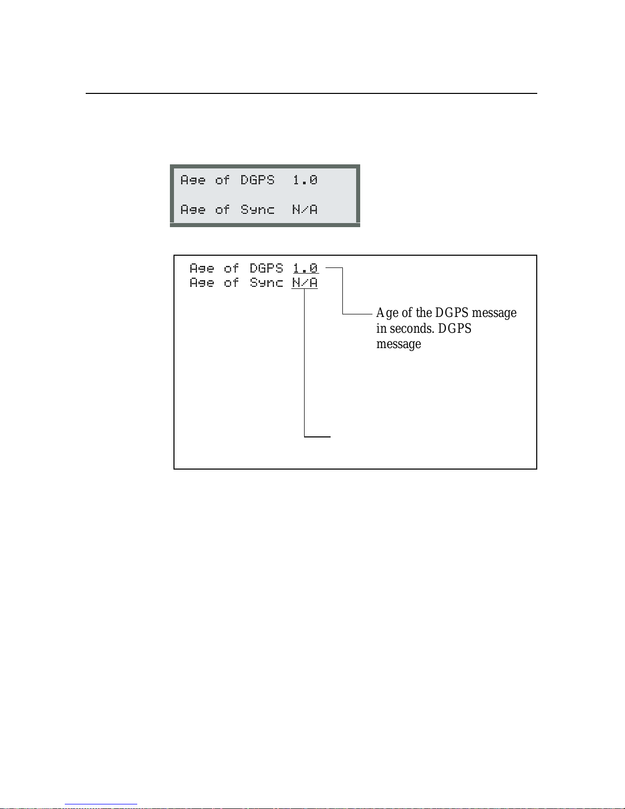
Status
5.2.4 DGPS Age
5
Figure 5-10 explains the following
- <
- < %
- <
- < %
Age of Sync is used with satellite
differential only.
DGPS Age
screen.
Age of the DGPS message
in seconds. DGPS
messages should be less
than 30 seconds old. Newer
correction messages yield
better accuracy than older
correction messages.
5-14
Figure 5-10 DGPS Age
Press 2 to return to the main m enu.
Ag
GPS 124/132 Operation Manual
Page 91

5 Status
5.3 Satellite DGPS Status
GPS 132 in Satellite Mode Only)
(
Ag
*
Note – Press 1 + 2 to return to the
an
S appears in lower-left corner. This ensures you are in satellite
mode.
To view the statu s of t he DGPS inf ormation, p ress 3 until the
screen appears. Pres s 2. Press 3 until
to move through each screen.
2
!
2
!!
&
Home
screen. Press 4 until
DGPS Status
appears. Press
Status
Ag
GPS 124/132 Operation Manual 5-15
Page 92

Status
5.3.1 Satellite Differential Status
5
Figure 5-11 e xplains the following
$ )08
,=
$ )08
Differenti al Satellite frequency.
Frequency depends on receiver
location and the satell ite
differential provider.
,=
LI 3.2 indicates the strength of
the differential satellite lock.
Avalue greater than
acceptable.
Satellite Dif f erential Status
is
screen.
5-16
Differential satellite signal-to-noise
ratio (See GPS Satellite Information,
page 5-7).
Figure 5-11 Satellite Differential Status
Ag
GPS 124/132 Operation Manual
Page 93
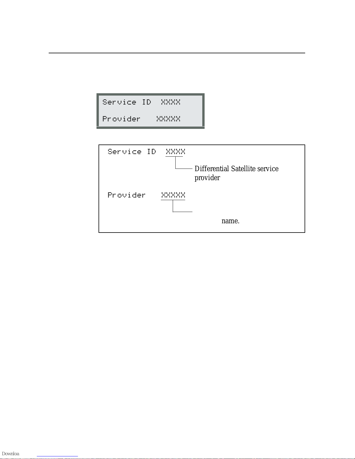
5 Status
5.3.2 Service Provider ID
Figure 5-12 explains the following
= >>>>
* >>>>>
= >>>>
Service Provider ID
Differenti al Satellite service
provider ID.
* >>>>>
Differenti al Satellite service
provider name.
Figure 5-12 Service Provider ID
screen.
Ag
GPS 124/132 Operation Manual 5-17
Page 94

Status
5.3.3 DGPS Data Source
5
Figure 5-13 explains the following
$$ .
>>>>> ?????
$$ .
>>>>> ?????
DGPS Data Source
Service provider network or reference
station ID. This reference station
supplies correction values for the
current position fix. For information
about individual reference stations,
contact your service provi der.
Figure 5-13 DGPS Data Source
screen.
5-18
Ag
GPS 124/132 Operation Manual
Page 95

5 Status
5.3.4 DGPS Age
Figure 5-14 explains the following
- <
- < %
- <
Shows the age of the latest
satellite differential correction.
DGPS messages should be less
than 30 seconds old. N ewer
correction values yield better
accuracy than older values.
- < %
Displays the number of seconds
since the last differential signal
synchronization data was
received. This data is used to
identify the DGPS service. If the
synchronizati on messages ar e not
received, the receiver may not be
listening to the correct signal.
There may be some form of
jamming or electronic
interference affecting the data
content.
DGPS Age
screen.
Figure 5-14 DGPS Age
Ag
GPS 124/132 Operation Manual 5-19
Page 96

Status
5.3.5 Racal-LandStar Service Info
Table 5-5 describes options available in the following
Racal-LandStar Service Info
4
$$#,$*$
=<
(! '* >>>>>
Press 4 to move through the options.
Table 5-5 Racal-LandStar Subscription Options
Option Meaning
5
screen.
User Code
XXXXX
Access Unknown Subscription status is unknown.
User Enabled Subscription is active.
User Disabled Subscription is inactive.
Version XX.XX Racal-LandStar decoder software version.
Racal-LandStar user code. This number is
needed when subscribing to
Racal-LandStar service.
For subscription installation information, see Appendix F, Activating
a Satellit e DGPS Service.
5-20
Ag
GPS 124/132 Operation Manual
Page 97

5 Status
5.3.6 OmniSTAR Service Info
Table 5-6 describes the options available in the following
OmniSTAR Service In fo
4
2 =<
(! '* >>>>>>>>
Press 4 to move through the options.
Table 5-6 OmniSTAR Subscription Options
Option Meaning
Init Decoder OmniSTAR decoder is initializing.
Decoder Ready 1-4 Decoder is ready, but DGPS data not yet
screen.
received.
Access Confirmed Access confirmed, but no data yet.
Received Data System providing DGPS corrections.
No Recent Data Data has been received in the past, but
not in the last 10 seconds.
No Decoder Available OmniSTAR decoder not available or is not
operating correctly.
Access Unknown No access to OmniSTAR DGPS.
Stop XX/XX/XX End date of OmniSTAR DGPS
subscription.
For subscription installation information, see Appendix F, Activating
a Satellit e DGPS Service.
Ag
GPS 124/132 Operation Manual 5-21
Page 98

Status
5.3.7 Service ID and Initialization Vector (IV)
5
The
Service ID and Initialization Vector (IV)
4
= =
>>>>> >>>> >>>>
screen is shown below:
Press 4 to cycle through the AgGPS Service ID and IV database.
This database contains information about supported DGPS services.
You can add to this database in configuration if you require a service
not automatically listed.
Press 2 to return to the main m enu.
5-22
Ag
GPS 124/132 Operation Manual
Page 99

5 Status
5.4 Receiver Status
From the
Status
!!
!!
Status
screen. Use 2 to move through the screens.
2
5.4.1 Time Screen
Figure 5-15 explains the following
: 2 (:'
)
: 2 (:'
)
screen, press 2. Press 3 to display the
&
screen.
Time
Receiver
The curren t time in UTC
(Universal Coordinated Time).
UTC time is Greenwich Mean
Time plus a few seconds.
Figure 5-15 Time
Ag
GPS 124/132 Operation Manual 5-23
Page 100

Status
5.4.2 Date and GPS Week
5
Figure 5-16 explains the following
$ 977
6; 97
$ 977
Current da te.
6; 97
Number of GPS weeks since
January 6, 1980. Each Sunday at
roughly 12:00 a.m., Greenwich
Mean Time, a new GPS week
begins.
Date and GPS Week
screen.
5-24
Figure 5-16 Date and GPS Week
Ag
GPS 124/132 Operation Manual
 Loading...