

Page 1

AgGPS™ 122
Operation Manual
Part Number: 30921-00
Revision: B
Date: March 1997
Trimble Navigation Limited
Surveying & Mapping Division
645 North Mary Av enue
Post Office Box 3642
Sunnyvale, CA 94088-3642
U.S.A.
+1-800-827-8000 in North America
+1-408-481-8000 International
FAX: +1-408-481-8214
Trimble
Precision Agricultural Systems
9290 Bond Street, Suite 102
Overland Park, KS 66214
U.S.A.
+1-800-865-7438 in North America
+1-913-495-2700 International
FAX: +1-913-495-2750
Page 2

Trimble Navigation Europe Limited
Trimble House, Meridian Office Park
Osborn Way, Hook
Hampshire RG27 9HX
ENGLAND
+44-1256-760-150
FAX: +44-1256-760-148
Trimble Navigation Singapore PTE Limited
300 Beach Road
#34-05, The Concourse
Singapore 199555
SINGAPORE
+65-296-2700
FAX: +65-296-8033
Trimble Japan K.K.
Sumitomo Hamamatsu-cho, Building 10F
1-18-16 Hamamatsu-c ho Min ato -ku
Tokyo 105
JAPAN
+81-3-5472-0880
FAX: +81-3-5472-2326
Trimble Navigation New Zealand Limited
11 Birmingham Drive
P.O. Box 8729 Riccarton
Christchurch
NEW ZEALAND
+64-3-339-1400
FAX: +64-3-339-1417
Copyrights
© 1997 Trimble Navigation Limited. All rights reserved. No part of this manual may be
copied, photocopied, reproduced, translated, or reduced to any electronic medium or machinereadable form without prior written consent from Trimble Navigation Limited.
Printed in the United States of America. Printed on recycled paper.
Page 3

Revision Notice
This is the first release of the AgGPS 122 Operation Manual, Part Number 30921-00,
Revision B, March 1997.
Trademarks
AgGPS, 4000DS, 4000DSR, 4000MSK, 4000MSK DGPS Reference Station, 4000RS,
4000RSR, 4000SE, 4000SSE, 4000SSi, Land Surveyor II, Land Surveyor IID, System
Surveyor II, ProBeacon, Geodetic Surveyor, Geodetic System Surveyor, GIS Surveyor, DSM,
DSMPro, NavBeacon XL, TRIMTALK 900, TRIMTALK 450, TANS, and TSIP are
trademarks of Trimble Navigation Limited. IBM is a registered trademark of International
Business Machines, Inc. MS-DOS and W indo ws is a tradem ark of Microsoft Corp oration. Intel
is a trademark of Intel Corporation. All other brand names are trademarks of their respective
holders.
Disclaimer of Warranty
EXCEPT AS INDICATED IN “LIMITED WARRANTY” HEREIN, TRIMBLE HARDWARE,
SOFTWARE, FIRMWARE AND DOCUMENTATION IS PROVIDED “AS IS” AND WITHOUT
EXPRESS OR LIMITED WARRANTY OF ANY KIND BY EITHER TRIMBLE OR ANYONE WHO
HAS BEEN INVOLVED IN ITS CREATION, PRODUCTION, OR DISTRIBUTION INCLUDING
BUT NOT LIMITED TO THE IMPLIED WARRANTIES OF MERCHANTABILITY AND FITNESS
FOR A PARTICULAR PURPOSE. THE ENTIRE RISK, AS TO THE QUALITY AND
PERFORMANCE OF THE TRIMBLE HARDWARE, SOFTWARE, FIRMWARE AND
DOCUMENTATION, IS WITH YOU. SOME STATES DO NOT ALLOW THE EXCLUSION OF
IMPLIED WARRANTIES, SO THE ABOVE EXCLUSION MAY NOT APPLY TO YOU.
Limitation of Liability
IN NO EVENT WILL TRIMBLE OR ANY PERSON INVOLVED IN THE CREATION,
PRODUCTION, OR DISTRIBUTION OF THE TRIMBLE PRODUCT BE LIABLE TO YOU ON
ACCOUNT OF ANY CLAIM FOR ANY DAMAGES, INCLUDING ANY LOST PROFITS, LOST
SAVINGS, OR OTHER SPECIAL, INCIDENTAL, CONSEQUENTIAL, OR EXEMPLARY
DAMAGES, INCLUDING BUT NOT LIMITED TO ANY DAMAGES ASSESSED AGAINST OR
PAID BY YOU TO ANY THIRD PARTY, RISING OUT OF THE USE, LIABILITY TO USE,
QUALITY OR PERFORMANCE OF SUCH TRIMBLE PRODUCT INCLUDING HARDWARE,
SOFTWARE, FIRMWARE, AND DOCUMENTATION, EVEN IF TRIMBLE OR ANY SUCH
PERSON OR ENTITY HAS BEEN ADVISED OF THE POSSIBI LITY OF D AM A GES, OR FOR ANY
CLAIM BY ANY OTHER PART Y. SOME STATES DO NOT ALLOW THE LIMITATION OR
EXCLUSION OF LIABILITY FOR INCIDENTAL OR CONSEQUENTIAL DAMAGES SO, THE
ABOVE LIMITATIONS MAY NOT APPLY TO YOU.
Page 4

Software and Firmware Limited Warranty
Trimble warrants that Software and Firmware products will substantially conform to the
published specifications provided it is used with the Trimble products, computer products, and
operating system for which it was designed. For a period of ninety (90) days, commencing
thirty (30) da ys after ship ment from Trimble, Trim ble also w arrants that the magnet ic media on
which Software and Firmware are distributed and the documentation are free from defects in
materials and workmanship. During the ninety (90) day warranty period, Trimble will replace
defective media or documentation, or correct substantial program errors at no charge. If
Trimble is unable to replace defective media or documentation, or correct program errors,
Trimble will refund the price paid for The Software. These are your sole remedies for any
breach in warranty.
Hardware Limited Warranty
Trimble Navigation Limited products are warranted against defects in material and
workmanship for a period of one year. The warranty period shall commence thirty (30) days
after shipment from Trimble’s factory. Warranty service will be provided at a designated
Trimble Service Center . T rimble will at its option either repair or replace products that prove to
be defective. The Customer shall pay all shipping charges for products return ed to Trimble for
warranty service. Trimble shall pay all shipping charges for the return of products to the
Customer. This warranty shall not apply to defects resulting from:
1. Improper or inadequate maintenance by the buyer
2. Buyer-supplied software or interfacing
3. Unauthorized modification or misuse
4. Operation outside of the environmental specifications of the product
5. Improper installation, where applicable
6. Lightning or other electrical discharge
7. Fresh or salt water immersion or spray
8. Normal wear and tear on consumable parts (for example, batteries)
No other warranty is expressed or implied. Trimble Navigation Limited specifically disclaims
the implied warranties of fitness for a particular purpose and merchantability.
Page 5

Table of Contents
Preface
Scope and Audience . . . . . . . . . . . . . . . . . . . . . . . . xvii
Organization . . . . . . . . . . . . . . . . . . . . . . . . . . . . xviii
Related Publications . . . . . . . . . . . . . . . . . . . . . . . . xix
Related Information . . . . . . . . . . . . . . . . . . . . . . . . xix
Update Notes . . . . . . . . . . . . . . . . . . . . . . xx
Trimble Bulletin Board Service . . . . . . . . . . . . . xx
FTP Site . . . . . . . . . . . . . . . . . . . . . . . . . xx
WWW Site. . . . . . . . . . . . . . . . . . . . . . . . xx
Technical Assistance. . . . . . . . . . . . . . . . . . . xxi
FaxBack . . . . . . . . . . . . . . . . . . . . . . . . . xxi
Reader Comment Form . . . . . . . . . . . . . . . . . . . . . . xxi
Document Conventions . . . . . . . . . . . . . . . . . . . . . . xxii
Notes, Tips, Cautions, and Warnings . . . . . . . . . . . . . . . xxiii
1Overview
1.1 AgGPS 122 Hardware . . . . . . . . . . . . . . . . . . . . . . . 1-2
1.2 Standard Features . . . . . . . . . . . . . . . . . . . . . . . . . 1-3
1.3 Optional Accessories and Components . . . . . . . . . . . . . . 1-4
1.4 Operating Characteristics . . . . . . . . . . . . . . . . . . . . . 1-5
1.4.1 Integrity Monitoring . . . . . . . . . . . . . . . . . . . 1-5
1.4.2 Part Numbers . . . . . . . . . . . . . . . . . . . . . . 1-6
AgGPS 122 Operation Manual v
Page 6

Table of Contents
1.5 Receiver Connections . . . . . . . . . . . . . . . . . . . . . . . 1-7
1.5.1 Port A – RTCM Input and NMEA Output . . . . . . . 1-7
1.5.2 Port B – TSIP Input and Output . . . . . . . . . . . . . 1-8
1.5.3 1 PPS Output . . . . . . . . . . . . . . . . . . . . . . 1-8
1.6 TSIP Talker Software . . . . . . . . . . . . . . . . . . . . . . . 1-8
1.7 Differential GPS Positioning. . . . . . . . . . . . . . . . . . . . 1-9
1.7.1 Sources of DGPS Error . . . . . . . . . . . . . . . . . 1-9
1.7.2 Critical Factors Affecting DGPS Accuracy . . . . . . . 1-11
1.8 Beacon Signal Processing . . . . . . . . . . . . . . . . . . . . . 1-15
1.8.1 Beacon Pre-filtering . . . . . . . . . . . . . . . . . . . 1-16
1.8.2 Beacon Automatic Gain Control . . . . . . . . . . . . 1-16
1.8.3 Beacon Analog-to-Digital Conversion . . . . . . . . . 1-16
1.8.4 Beacon Digital Signal Processing . . . . . . . . . . . . 1-16
1.8.5 Beacon I/O Processing. . . . . . . . . . . . . . . . . . 1-17
1.9 Combined Antenna . . . . . . . . . . . . . . . . . . . . . . . . 1-18
1.10 Working with Datums . . . . . . . . . . . . . . . . . . . . . . . 1-18
2 Installing the AgGPS 122 Receiver
2.1 Unpacking and Inspecting the Shipment . . . . . . . . . . . . . 2-2
2.1.1 Opening the Shipping Carton . . . . . . . . . . . . . . 2-2
2.1.2 Reporting Shipping Problems . . . . . . . . . . . . . . 2-3
2.2 Installation Guidelines . . . . . . . . . . . . . . . . . . . . . . . 2-3
2.2.1 Choosing a Location. . . . . . . . . . . . . . . . . . . 2-3
2.2.2 Considering Environmental Conditions . . . . . . . . . 2-4
2.2.3 Input Power Requirements . . . . . . . . . . . . . . . 2-4
2.3 Mounting the Receiver. . . . . . . . . . . . . . . . . . . . . . . 2-5
2.4 Mounting the Antenna . . . . . . . . . . . . . . . . . . . . . . . 2-6
2.4.1 Sources of Electrical Interference . . . . . . . . . . . . 2-6
2.4.2 Pole Mounting the Antenna . . . . . . . . . . . . . . . 2-7
2.4.3 Magnetic Mounting the Antenna . . . . . . . . . . . . 2-8
vi AgGPS 122 Operation Manual
Page 7

2.5 Routing and Connecting the Antenna Cable . . . . . . . . . . . . 2-9
2.5.1 Routing and Connecting the Antenna Cable . . . . . . 2-10
2.6 Connecting the Interface Devices . . . . . . . . . . . . . . . . . 2-11
2.6.1 Data and Power Port Connectors . . . . . . . . . . . . 2-11
2.6.2 Standard Interface Cables . . . . . . . . . . . . . . . . 2-13
2.6.3 Optional Interface Cables . . . . . . . . . . . . . . . . 2-14
2.6.4 Connecting a Ag Leader Yield Monitor 2000. . . . . . 2-15
2.6.5 Connecting a Micro-Trak Data Logger . . . . . . . . . 2-16
2.6.6 Connecting the Receiver to a PC . . . . . . . . . . . . 2-17
2.6.7 Using the Dual Data and Power Cable . . . . . . . . . 2-19
2.7 Connecting the Switched Power Source . . . . . . . . . . . . . . 2-20
3 Configuring the AgGPS 122 Receiver
3.1 TSIP Talker Overview . . . . . . . . . . . . . . . . . . . . . . . 3-1
Table of Contents
3.1.1 Understanding TSIP Protocol . . . . . . . . . . . . . . 3-2
3.1.2 TSIP Talker Installation . . . . . . . . . . . . . . . . . 3-2
3.1.3 Starting TSIP Talker in Windows 3.1 . . . . . . . . . . 3-2
3.1.4 Starting TSIP Talker in Windows 95 . . . . . . . . . . 3-3
3.1.5 TSIP Talker Menus . . . . . . . . . . . . . . . . . . . 3-3
3.1.6 Working with TSIP Talker Windows . . . . . . . . . . 3-6
3.1.7 Finding Help. . . . . . . . . . . . . . . . . . . . . . . 3-7
3.2 Defining Setup Options . . . . . . . . . . . . . . . . . . . . . . 3-8
3.2.1 Configuring the PC Serial Port . . . . . . . . . . . . . 3-8
3.2.2 Configuring Port A . . . . . . . . . . . . . . . . . . . 3-10
3.2.3 Configuring Port B . . . . . . . . . . . . . . . . . . . 3-13
3.2.4 TSIP Break . . . . . . . . . . . . . . . . . . . . . . . 3-15
3.2.5 Units . . . . . . . . . . . . . . . . . . . . . . . . . . . 3-16
3.3 Configuring GPS Parameters . . . . . . . . . . . . . . . . . . . 3-16
3.3.1 Configuring the Approximate Initial Position. . . . . . 3-17
3.3.2 Configuring GPS Mask Parameters . . . . . . . . . . . 3-19
AgGPS 122 Operation Manual vii
Page 8

Table of Contents
3.3.3 Configuring the Advanced Receiver Parameters . . . . 3-23
3.3.4 Configuring the 2D Altitude. . . . . . . . . . . . . . . 3-28
3.3.5 Configuring NMEA Output . . . . . . . . . . . . . . . 3-29
3.3.6 Configuring the Advanced NMEA Options. . . . . . . 3-31
3.3.7 Configuring the Receiver for DGPS Input . . . . . . . 3-36
3.3.8 Configuring DGPS Output . . . . . . . . . . . . . . . 3-38
3.3.9 Resetting the Receiver . . . . . . . . . . . . . . . . . . 3-39
3.4 Configuring Beacon Parameters . . . . . . . . . . . . . . . . . . 3-40
3.4.1 Selecting the Channel Control. . . . . . . . . . . . . . 3-41
3.4.2 Working with the Beacon List. . . . . . . . . . . . . . 3-43
3.4.3 Controlling the Health of Radiobeacons . . . . . . . . 3-48
3.4.4 Displaying Wideband FFT Diagnostic Plots . . . . . . 3-50
4 Viewing Reports
4.1 Receiver Information Report. . . . . . . . . . . . . . . . . . . . 4-2
4.2 Analog Status Report . . . . . . . . . . . . . . . . . . . . . . . 4-4
4.2.1 Position Info Report . . . . . . . . . . . . . . . . . . . 4-5
4.2.2 Satellite Info Report . . . . . . . . . . . . . . . . . . . 4-8
4.2.3 Sky Plot . . . . . . . . . . . . . . . . . . . . . . . . . 4-12
4.2.4 Beacon Channel Status Report . . . . . . . . . . . . . 4-14
4.2.5 DGPS Message Summary Report . . . . . . . . . . . . 4-17
A Specifications
A.1 Physical Characteristics . . . . . . . . . . . . . . . . . . . . . . A-1
A.2 Performance Characteristics . . . . . . . . . . . . . . . . . . . . A-2
B DGPS Radiobeacons
C Scorpio™
Option
viii AgGPS 122 Operation Manual
Page 9

D NMEA-0183 Messages
D.1 NMEA-0183 Message Structure . . . . . . . . . . . . . . . . . . D-1
D.1.1 Symbols and Delimiters . . . . . . . . . . . . . . . . . D-3
D.1.2 Checksum Values . . . . . . . . . . . . . . . . . . . . D-4
D.1.3 Field Formats . . . . . . . . . . . . . . . . . . . . . . D-4
D.2 NMEA Message Summary . . . . . . . . . . . . . . . . . . . . D-6
D.3 ALM . . . . . . . . . . . . . . . . . . . . . . . . . . . . . . . . D-7
D.4 GGA . . . . . . . . . . . . . . . . . . . . . . . . . . . . . . . . D-8
D.5 GLL . . . . . . . . . . . . . . . . . . . . . . . . . . . . . . . . D-8
D.6 GSA . . . . . . . . . . . . . . . . . . . . . . . . . . . . . . . . D-10
D.7 GSV . . . . . . . . . . . . . . . . . . . . . . . . . . . . . . . . D-11
D.8 MSS . . . . . . . . . . . . . . . . . . . . . . . . . . . . . . . . D-12
D.9 RMC . . . . . . . . . . . . . . . . . . . . . . . . . . . . . . . . D-13
D.10 VTG . . . . . . . . . . . . . . . . . . . . . . . . . . . . . . . . D-14
Table of Contents
D.11 ZDA . . . . . . . . . . . . . . . . . . . . . . . . . . . . . . . . D-15
E Cables and Connectors
E.1 Port A and Port B Connectors . . . . . . . . . . . . . . . . . . . E-2
E.2 Ag Leader Interface Cable. . . . . . . . . . . . . . . . . . . . . E-3
E.3 Data Interface Cable . . . . . . . . . . . . . . . . . . . . . . . . E-4
E.4 Dual Data Interface Cable. . . . . . . . . . . . . . . . . . . . . E-5
E.5 Data Extension Cable . . . . . . . . . . . . . . . . . . . . . . . E-6
E.6 Case AFS Cable . . . . . . . . . . . . . . . . . . . . . . . . . . E-7
AgGPS 122 Operation Manual ix
Page 10

Table of Contents
F Troubleshooting
F.1 Checking Tracking Status . . . . . . . . . . . . . . . . . . . . . F-1
F.1.1 Isolating GPS Tracking Problems . . . . . . . . . . . . F-2
F.1.2 Isolating Radiobeacon Tracking Problems . . . . . . . F-3
F.2 Lithium Battery Failure . . . . . . . . . . . . . . . . . . . . . . F-4
G Option Summary
Index
x AgGPS 122 Operation Manual
Page 11

List of Figures
Figure 1-1. AgGPS 122 Receiver. . . . . . . . . . . . . . . . . . . . . . 1-1
Figure 1-2. Back Panel . . . . . . . . . . . . . . . . . . . . . . . . . . . 1-7
Figure 2-1. Antenna Cable Connections . . . . . . . . . . . . . . . . . . 2-9
Figure 2-2. Data Interface (and Power) Ports. . . . . . . . . . . . . . . . 2-11
Figure 2-3. Connecting a Ag Leader Yield Monitor 2000 . . . . . . . . . 2-15
Figure 2-4. Interfacing a Micro-Trak Data Logger . . . . . . . . . . . . . 2-16
Figure 2-5. Interfacing the Receiver to a PC . . . . . . . . . . . . . . . . 2-17
Figure 2-6. Connecting a PC with a Dual Interface Cable . . . . . . . . . 2-19
Figure 3-1. TSIP Talker Menu Bar . . . . . . . . . . . . . . . . . . . . . 3-3
Figure 3-2. Comport Dialog . . . . . . . . . . . . . . . . . . . . . . . . 3-8
Figure 3-3. Setup Port-A Dialog . . . . . . . . . . . . . . . . . . . . . . 3-11
Figure 3-4. Units Dialog . . . . . . . . . . . . . . . . . . . . . . . . . . 3-16
Figure 3-5. Initial Position Dialog . . . . . . . . . . . . . . . . . . . . . 3-17
Figure 3-6. Receiver Parameters Dialog . . . . . . . . . . . . . . . . . . 3-19
Figure 3-7. Advanced Receiver Parameters. . . . . . . . . . . . . . . . . 3-23
Figure 3-8. 2D Altitude Dialog . . . . . . . . . . . . . . . . . . . . . . . 3-28
Figure 3-9. NMEA Output Dialog . . . . . . . . . . . . . . . . . . . . . 3-29
Figure 3-10. Advanced NMEA Options . . . . . . . . . . . . . . . . . . . 3-31
Figure 3-11. DGPS Input. . . . . . . . . . . . . . . . . . . . . . . . . . . 3-36
Figure 3-12. Receiver Reset . . . . . . . . . . . . . . . . . . . . . . . . . 3-39
Figure 3-13. Beacon Channel Control . . . . . . . . . . . . . . . . . . . . 3-41
Figure 3-14. Beacon List. . . . . . . . . . . . . . . . . . . . . . . . . . . 3-43
Figure 3-15. Beacon Information . . . . . . . . . . . . . . . . . . . . . . 3-46
Ag
GPS 122 Operation Manual xi
Page 12

List of Figures
Figure 3-16. Beacon Health Control . . . . . . . . . . . . . . . . . . . . . 3-48
Figure 3-17. Wideband FFT . . . . . . . . . . . . . . . . . . . . . . . . . 3-50
Figure 4-1. Receiver Information Report. . . . . . . . . . . . . . . . . . 4-2
Figure 4-2. Analog Status Report. . . . . . . . . . . . . . . . . . . . . . 4-4
Figure 4-3. Position Info Settings Dialog. . . . . . . . . . . . . . . . . . 4-5
Figure 4-4. Position Info Report . . . . . . . . . . . . . . . . . . . . . . 4-7
Figure 4-5. Satellite Info Settings Report. . . . . . . . . . . . . . . . . . 4-8
Figure 4-6. Satellite Info Report . . . . . . . . . . . . . . . . . . . . . . 4-11
Figure 4-7. Sky Plot Settings . . . . . . . . . . . . . . . . . . . . . . . . 4-12
Figure 4-8. Sky Plot. . . . . . . . . . . . . . . . . . . . . . . . . . . . . 4-13
Figure 4-9. Beacon Channel Status Report . . . . . . . . . . . . . . . . . 4-14
Figure 4-10. DGPS Message Summary . . . . . . . . . . . . . . . . . . . 4-17
Figure D-1. Sample ZDA Message Structure . . . . . . . . . . . . . . . . D-1
Figure F-1. Front Panel . . . . . . . . . . . . . . . . . . . . . . . . . . . F-1
xii
Ag
GPS 122 Operation Manual
Page 13

List of Tables
Table 1-1. Part Numbers . . . . . . . . . . . . . . . . . . . . . . . . . . 1-6
Table 2-1. AgGPS 122 Components. . . . . . . . . . . . . . . . . . . . 2-2
Table 2-2. AgGPS 122 Upgrades . . . . . . . . . . . . . . . . . . . . . 2-2
Table 2-3. Optional Components . . . . . . . . . . . . . . . . . . . . . 2-3
Table 2-4. Standard Cables . . . . . . . . . . . . . . . . . . . . . . . . 2-13
Table 2-5. Optional Cables. . . . . . . . . . . . . . . . . . . . . . . . . 2-14
Table 3-1. TSIP Talker Menus. . . . . . . . . . . . . . . . . . . . . . . 3-4
Table 3-2. Window Menu Commands. . . . . . . . . . . . . . . . . . . 3-6
Table 3-3. Help Menu Commands. . . . . . . . . . . . . . . . . . . . . 3-7
Table 3-4. Comport Parameters . . . . . . . . . . . . . . . . . . . . . . 3-9
Table 3-5. Port A Default Settings. . . . . . . . . . . . . . . . . . . . . 3-10
Table 3-6. Port A Parameters . . . . . . . . . . . . . . . . . . . . . . . 3-12
Table 3-7. Port-B Default Settings. . . . . . . . . . . . . . . . . . . . . 3-14
Table 3-8. TSIP Break Default Settings . . . . . . . . . . . . . . . . . . 3-15
Table 3-9. Initial Position Parameters . . . . . . . . . . . . . . . . . . . 3-18
Table 3-10. Receiver Parameters Settings. . . . . . . . . . . . . . . . . . 3-19
Table 3-11. Position Mode Parameter Settings . . . . . . . . . . . . . . . 3-20
Table 3-12. Dynamic Code Parameter Settings. . . . . . . . . . . . . . . 3-22
Table 3-14. Overdetermined Mode Settings . . . . . . . . . . . . . . . . 3-27
Table 3-15. NMEA-0183 Messages. . . . . . . . . . . . . . . . . . . . . 3-30
Table 3-16. NMEA VTG Options. . . . . . . . . . . . . . . . . . . . . . 3-32
Table 3-17. NMEA RMC Speed Options . . . . . . . . . . . . . . . . . . 3-33
Table 3-18. DGPS Input Options . . . . . . . . . . . . . . . . . . . . . . 3-36
Ag
GPS 122 Operation Manual xiii
Page 14

List of Tables
Table 3-19. DGPS Mode Options . . . . . . . . . . . . . . . . . . . . . . 3-37
Table 3-20. External DGPS Source Options . . . . . . . . . . . . . . . . 3-38
Table 3-21. Reset Options. . . . . . . . . . . . . . . . . . . . . . . . . . 3-39
Table 3-22. Mode Parameter . . . . . . . . . . . . . . . . . . . . . . . . 3-42
Table 3-23. Beacon List Columns. . . . . . . . . . . . . . . . . . . . . . 3-44
Table 3-24. Beacon Information . . . . . . . . . . . . . . . . . . . . . . 3-47
Table 4-1. Receiver Information Report Fields . . . . . . . . . . . . . . 4-3
Table 4-2. Analog Status Report Fields . . . . . . . . . . . . . . . . . . 4-4
Table 4-3. Position Info Settings Options . . . . . . . . . . . . . . . . . 4-6
Table 4-4. Position Info Report Fields. . . . . . . . . . . . . . . . . . . 4-7
Table 4-5. Satellite Information Fields . . . . . . . . . . . . . . . . . . 4-9
Table 4-6. Beacon Channel Status Fields . . . . . . . . . . . . . . . . . 4-15
Table B-1. Worldwide DGPS Radiobeacon List, August 1996 . . . . . . B-2
Table D-1. Sample ZDA Message Structure . . . . . . . . . . . . . . . . D-2
Table D-2. Supported NMEA-0183 Messages. . . . . . . . . . . . . . . D-6
Table D-3. ALM Message Fields. . . . . . . . . . . . . . . . . . . . . . D-7
Table D-4. GGA Message Fields. . . . . . . . . . . . . . . . . . . . . . D-8
Table D-5. GLL Message Fields . . . . . . . . . . . . . . . . . . . . . . D-9
Table D-6. GSA Message Fields . . . . . . . . . . . . . . . . . . . . . . D-10
Table D-7. GSV Message Fields . . . . . . . . . . . . . . . . . . . . . . D-11
Table D-8. MSS Message Fields . . . . . . . . . . . . . . . . . . . . . . D-12
Table D-9. RMC Message Fields. . . . . . . . . . . . . . . . . . . . . . D-13
Table D-10. VTG Message Fields . . . . . . . . . . . . . . . . . . . . . . D-14
Table D-11. ZDA Message Fields . . . . . . . . . . . . . . . . . . . . . . D-15
Table E-1. Connector Pin-out for AgGPS 122 Port A and Port B . . . . . E-2
Table E-2. Ag Leader Yield Monitor Cable Pin-out (Part 30660) . . . . . E-3
Table E-3. Data Interface Cable Pin-out (P/N 30945) . . . . . . . . . . . E-4
Table E-4. Dual Data Interface Cable Pin-out (Part 32015) . . . . . . . . E-5
Table E-5. Data Extension Cable Pin-out (P/N 30700) . . . . . . . . . . E-6
Table E-6. Case AFS Cable Pin-out (P/N 32609) . . . . . . . . . . . . . E-7
xiv
Ag
GPS 122 Operation Manual
Page 15

List of Tables
Table F-1. Tracking Status LEDs . . . . . . . . . . . . . . . . . . . . . F-2
Table G-1. Parameter Settings . . . . . . . . . . . . . . . . . . . . . . . G-1
Ag
GPS 122 Operation Manual xv
Page 16

List of Tables
xvi
Ag
GPS 122 Operation Manual
Page 17

Preface
Welcome to the AgGPS 122 Operation Manual. This manual
describes the installation and configuration of the AgGPS 122 which
combines the functionality of a differential GPS receiver and Beacon
receiver, packaged within a light weight, rugged, weatherproof
housing.
The AgGPS 122 utilizes Trimble’s advanced low-power, low noise,
high-accurac y Maxwell c hip techno logy to achi ev e real- time DGPS to
submeter accuracy. The AgGPS 122 receiver outputs both a selection
of standard NMEA-0183 messages and raw measurements in TSIP
(Trimble Standa rd Interface Protocol), offeri ng optimal flexibility
when interfacing wi th other instruments. The receiver also can be
configured to output a 1 PPS (pulse per second) strobe signal to
synchronize time with external instruments and to log event marker
input from external instruments.
The AgGPS 122 receiver contains a dual-channel, all-digital, fullyautomatic radiobeacon receiver for acqu iring DGPS radiobeacon
broadcasts conforming to the IALA standard.
Scope and Audience
Even if you have used other Global Positioning System (GPS)
receivers and Beacon receivers we recommend that you spend some
time reading this manual. The following section provides you with a
guide to this manual, as well as to ot her docume nta ti on included with
this product.
AgGPS 122 Operation Manual xvii
Page 18

Preface
Organization
This manual contains the following chapters and appendices:
•
•
•
•
•
Chapter 1, Overview, provides a brief overview of Differential
GPS, and AgGPS 122 components.
Chapter 2, Installing the AgGPS 122 Receiver, contains
installation and interfacing instructions for the AgGPS 122
receiver.
Chapter 3, Configuring the AgGPS 122 Receiver, gives
instructio ns for usi ng the TSIP Talker so ftwa re to conf ig ure the
receiver operating parameters and monitor receiver functions.
Chapter 4, Viewing Reports, gives instructions for using TSIP
Talker to view receiver configuration reports, satellite
information reports, and radiobeacon information reports.
Appendix A, Specifications, identifies the physical
characteristics and general specifications of the AgGPS 122
receiver.
Appendix B, DGPS Radiobeacons, contains a Trimble
•
compiled listing of differential radiobeacons and marine
radiobeacons.
Appendix C, Scorpio™
•
Option, describes the added
capabilities of the AgGPS 122 receiver with the Scorpio option.
Appendix D, NMEA-0183 Messages, describes the struct ure of
•
the selection of NMEA mess ages suppo rted b y the AgGPS 122
receiver.
Appendix E, Cable s and Conne ctors, i ncludes p in-out diag rams
•
for the standard and optional cables.
• Appendix F, Troubleshooting, gives guidelines for solving
potential problems.
xviii AgGPS 122 Operation Manual
Page 19

Related Publications
The AgGPS 122 recei ver publication set includes th ree manuals—the
AgGPS 122 Operation Manual, the optional TSIP Talker User’s
Guide, and the optional Differential Beacon GPS TSIP Reference.
The AgGPS 122 Operation Ma nual , P/N 30921-00, (this
•
manual) includes step-by-step instructions for installing the
AgGPS 122 receiver and guidelines for using the included
software programs to configure the operating parameters and
control receiver functions. Also included are guidelines for
interfacing the AgGPS 122 receiver to a PC and agricultural
instruments, information about the selection of NMEA
messages supported by the receiver, and connector pin-out
diagrams for Port A, Port B, and cable connections.
The TSIP Talker User’s Guide (P/N 30921-00) includes step-
•
by-step instructions for using th e TSIP Talker software to
configure Trimble products. The presentation of information is
generic and applies to several Trimble products. All of the
informatio n presented in the TSIP Talker User’s Guide is
included in the AgGPS 122 Operation Manual (see above).
Preface
The optional Differential Beacon GPS TSIP Reference (P/N
•
31157-00) includes detailed information about TSIP (Trimble
Standard Inter face Prot ocol) pack et struct ures, number for mats,
and conventions. The contents of TSIP command and report
packets are described in detail. A numerical and alphabetical
index of command and report packets is provided for quickly
locating the location of specific information about a packet.
This manual is required for system integrators who are
developing TSIP software applications.
Related Information
This manual contains system-wide, general information about the
AgGPS 122. The following sections discuss other sources of
information.
AgGPS 122 Operation Manual xix
Page 20

Preface
Update Notes
You will find a Warranty Activation Sheet with your AgGPS 122
receiver. By sending in your Warranty Activation Sheet, you are
automatically sent update notes as they become available. When you
receive these packages, read them. They contain important
information about sof twa re and h ardwa re cha nges. Contact your l ocal
Trimble Dealer for more information about the support agreement
contrac ts for software and firmwar e, and an exte nded warranty
programs for hardware.
Trimble Bulletin Board Service
If you have a modem, check the Trimble Surveying and Mapping
Bulletin Board Servi ce (BBS) on a r eg ular b asis f or app licat ion no tes,
new software release notices, and other information. The phone
numbers are:
+1-408-481-7800
communication parameters: 8, n, 1
FTP Site
Trimble maintains a FTP (File Transfer Protocol) site at the following
address:
ftp://ftp.t ri mble.com
WWW Site
Trimble maintains a WWW (Wo rld Wide Web) p age at the foll owing
address:
http://www.trimble.com
xx AgGPS 122 Operation Manual
Page 21

Technical Assistance
If you hav e probl ems and cann ot f in d the i nformat ion yo u need i n thi s
document, call the Trimble Technical Assistance Center (TAC). The
phone numbers are:
+1-800-767-4822 (in North America)
+1-408-481-6940 (International)
+1-408-737-6020 (fax)
You can call the Technical Assistance Center phones between 6 AM
to 6 PM Pacific Standard Time. A support technician will take your
call, help you determine the source of your problem, and provide you
with any technical assistance you might need.
FaxBack
FaxBack is a co mpletely automated f ax r esponse system for selec ti ng
documents and cat alogs (lists of available documents) to be faxed
back to a fax machine. Call from a tone-dialing phone and FaxBack
guides you through the call by playing a pre-recorded voice message.
Preface
The FaxBack system is available 24 hours a day, seven days a week.
You can order a variety of documents, including; data sheets,
application notes, technical documentation, configuration guides,
assembly drawings, and general information.
To call the FaxBack service, dial +1-408-481-7704 and follow the
instruc tions received.
Reader Comment Form
A reader comment form is provided at the end of this guide. If this
form is not available, comments and suggestions can be sent to:
Editor, AgGPS 122 Publications, Trimble Navigation Limited, 645
North Mary Avenue, Post Office Box 3642, Sunnyvale, CA 94088-
3642. All comments and suggestions become the property of Trimble
Navigation Limited.
AgGPS 122 Operation Manual xxi
Page 22

Preface
Document Conventions
Italics identify software menus, menu commands, dialog boxes, and
the dialog box fields.
SMALL CAPITALS identify DOS commands, directories, filenames,
and filename extensions.
Courier
is used to represent what you see printed on the screen by
the DOS s ystem or program.
Courier Bold
represents information that you must type in a
software screen or window.
[Return] or [Ctrl] + [C] identifies a hardware function key or key
combination that you must press on a PC.
Helvetica Bold represents a software command button.
xxii AgGPS 122 Operation Manual
Page 23

Notes, Tips, Cautions, and Warnings
Notes, tips, cautions, and warnings are used to emphasize important
information.
Note – Notes give additional significant information about the subject
*
F
I
to increase your knowledge, or guide your actions. A note can
precede or follow the text it references.
Tip – Indicates a shortcut or other time or labor-saving hint that can
help you make better use of the AgGPS 122 receiver System.
Caution – Cautions alert you to situations that could cause hardware
damage or software error. A caution precedes the text it references.
Preface
Warning – W arnings alert you to situations that could cause personal
M
AgGPS 122 Operation Manual xxiii
injury or unrecoverable data loss. A warning precedes the text it
references.
Page 24

Preface
xxiv AgGPS 122 Operation Manual
Page 25
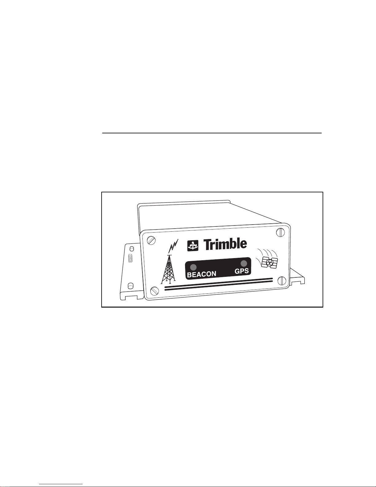
1Overview
The AgGPS 122 combines a GPS (Global Positioning System)
receiver and Beacon receiver into one unit, packaged in a lightweight, durable, waterproof housing (see Figure 1-1).
Figure 1-1.
The AgGPS 122 receiver is designed to interface to agricultural data
monitoring devices, such as the Ag Leader
Micro-Trak Data Logger, notebook PCs, or comparable instruments.
AgGPS 122 Operation Manual 1-1
Ag
GPS 122 Receiver
®
Yield Monitor 2000,
Page 26

Overview
The receiver features advanced low-power, low-noise, high-accuracy
Scorpion chip technology to achieve real-time DGPS submeter
accuracy. The recei v er fe ature s a multi -bit , fr ont-e nd digit izer with 12
1
channels
of continuous satellite tracking. Advanced carrier-phase
filtering techniques applied to exceptionally low-noise C/A code
measurements are used to gen erate real-time submet er pos it ions at an
optional maximum rate of 10 Hz, even under the most challenging
operating conditions.
The receiver also f eatures a dual-channel, all-digital, fully-a utomatic
Beacon receiver electronics for tracking broadcasts from radiobeacon
stations conforming to the IALA Standard. The receiver uses
advanced digital-signal processing techniques to track and
demodulate signals from rad iobeacon stations. The radiobeacons
operate in the MF (medium frequency) band from 283.5 kHz to
325 kHz.
This chapter gives a brief overview of the AgGPS 122 receiver.
1.1
Ag
GPS 122 Hardware
The AgGPS 122 receiver supports a subset of the standard NMEA0183 messages as outputs, raw measurements in Trimble Standard
Interface Protocol (TSIP), and 1 PPS (Pulse per Second) output,
offering optimal flexibility in interfacing with other instruments.
For optimum performance, the AgGPS 122 accepts differential GPS
corrections in the RTCM-SC-104 standard format transmitted from
radiobeacons. This pro duct provi des the benef its of e xcellent GPS and
Beacon performance in a compact package.
1.
Early models of the AgGPS 122 receiver supported 8 GPS channels.
1-2 AgGPS 122 Operation Manual
Page 27

1.2 Standard Features
The AgGPS 122 provides the following:
A multibit, front-end digitizer with 8 or 12 GPS (C/A-code)
•
tracking channels, carri er -pha se f ilt ering and ins tanta neous full
wav elength carrier-phase measurement s
Automatically switches radiobeacon channels to track the
•
closest or most powerful radiobeacons
Submeter accuracy: typically less than 1 meter RMS; assumes
•
at least 5 satellites, PDOP less than 4, and RTCM SC-104
standard format broadcasts from a radiobeacon station
Real-time processing
•
Optional 10 Hz maximum position and velocity update rate
•
Positioning based on carrier-phase filtered L1 pseudoranges
•
Velocity computations incorporate carrier-phase data
•
Overview
L1 C/A code outputs (maximum rate of 1 Hz)
•
Time of First Fix (TTFF): less than 30 seconds, typical
•
NMEA-0183 Message Outputs: ALM, GGA, GLL, GSA,
•
GSV, MSS, RMC, VTG, ZD A (t he def aul t NMEA me ssages t o
output are GGA, GSA, and VTG)
Two fully automatic radiobeacon acquisition modes and a
•
manual acquisition mode
Fast acquisition of radiobeacon beacon signals
•
Immunity to radiobeacon jamming signals
•
• Advanced techniques for combatting atmospheric noise in the
Beacon receiver electronics
• Automatic Beacon data integrity monitoring
• High sensitivity and low susceptibility to noise in Beacon
receiver electronics
• Two RS-232 serial/power ports
AgGPS 122 Operation Manual 1-3
Page 28

Overview
NMEA-0183 output/RTCM SC-104 Input
•
TSIP Input and output
•
Outputs 1 PPS (pulse per second) strobe signal on either serial
•
port, allowing an external instrument to synchronize its internal
timebase with the AgGPS 122 clock oscillator
TSIP Talker Software
•
Operation Manual
•
Combined L1 GPS and H-Field Loop Beacon antenna
•
Magnetic antenna mount
•
PC Data and power cables
•
PC/Micro-Trak Cable
•
Ag Leader Yield Monitor Cable
•
Antenna cable, 10-meter RG58, male TNC to male TNC
•
Scorpio™ System option
•
1.3 Optional Accessories and Components
The following accessories or components are also available:
Dual-connection data and power cable
•
12-foot data interface extension cable
•
Differential Beacon GPS TSIP Reference Manual
•
TSIP Talker Software User’s Guide
•
Field Pack
•
1-4 AgGPS 122 Operation Manual
Page 29

1.4 Operating Characteristics
After applying power, the AgGPS 122 receiver scans parameter
settings stored battery-backed memory and configures the unit for
operation.
The default configuration for the AgGPS 122 receiver allows the
receiver to operate in Auto Ra nge a cqui si tion mode. In this mode, t he
AgGPS 122 receiver automatically builds a radiobeacon database
containing a listing of the ten most powerful radiobeacons in the
vicinity and uses the closest beacon. Both Beacon channels are
configure d to search for and trac k the two nearest r adi obe acons in the
database. The unit demodulates the data carried on the radiobeacon
signal and outputs GPS NMEA messages to the interface device
through Port A.
Note – The AgGPS 122 receiver actually has two modes of automatic
*
radiobeacon signal acquisition and one manual mode of radiobeacon
signal acquisition. For detailed information, see Selecting the Channel
Control on page 3-41.
Overview
When configured for Manual acquisition mode, the AgGPS 122
receiver searches for a user-defined radiobeacon station frequency.
Once a signal is acquired, the AgGPS 122 receiver starts to perform
differential positioning.
1.4.1 Integrity Monitoring
In the Auto Range and Auto Power radiobeacon acquisition modes,
the AgGPS 122 receiver continuously monitors the integrity of the
data received from the differential radiobeacon(s). If AgGPS 122
detects excessive parity errors in the data stream, the receiver
automati cally switches to a di ffer ent radiobeacon, if one is available.
When the BEACON indicator light flashes twice per second, the
receiver is no longer receiving a usable radiobeacon signal.
AgGPS 122 Operation Manual 1-5
Page 30

Overview
In Manual acquisition mode, the receiver can only use a single userdefined radiobeacon station frequency.
1.4.2 Part Numbers
Table 1-1 lists the part numbers for the AgGPS 122 product and
options.
Table 1-1. Part Numbers
Description P/N
Ag
GPS 122 product, 1 Hz 29837-00
Optional Parts
10 Hz Upgrade 33176-10
Scorpio Upgrade 33176-20
10-inch, Dual-connection data and power cable 32015
12-foot data interface extension cable 30700
AgGPS 122 to Case AFS cable 32609
TSIP Talker Manual 31889-00
Differential Beacon GPS TSIP Reference 31157-00
Extended hardware warranty - 1 year 30944-21
Extended hardware warranty - 4 years 30944-24
Firmware Update Service - 1 year 30944-11
Firmware Update Service - 4 years 30944-14
The AgGPS 122 product includes a receiver, antenna, magnetic
antenna mount, data cables, operation manual, and software.
1-6 AgGPS 122 Operation Manual
Page 31

1.5 Receiver Connections
Figure 1-2 shows the AgGPS 122 receiver back panel and its
associated ports.
Figure 1-2. Back Panel
Overview
1.5.1 Port A – RTCM Input and NMEA Output
On the back panel of the AgGPS 122, the connector labeled Port A is
used to input RTCM SC-104 data and to output NMEA 0183
messages between the interface device and the AgGPS 122 receiver.
Both Port A and Port B can accept power from an interface device or
external p ower source.
The Ag Leader Yield Monitor 2000 can supply power to the AgGPS
122 receiver through Port A (see Figure 2-3) using instrument
interface cable (P/N 30660).
Power from an e xter nal power source is input through Port A using an
alternate cabling scheme. For an example of connecting power from
an external power source, see Connecting a Micro-Trak Data Logger
on page 2-16.
AgGPS 122 Operation Manual 1-7
Page 32

Overview
1.5.2 Port B – TSIP Input and Output
The connector labeled Port B is used to inte rface a PC to the AgGPS
122 receiver for inputting and outputting TSIP (Trimble Standard
Interface Protocol) packets (see Figure 2-5). The PC data and power
cable (P/N 30945) is used to connect the PC to the AgGPS 122
receiver.
TSIP command packets are used to set GPS and Beacon parameters,
and TSIP report pac ket s ar e used t o monitor the GPS and radi obeacon
data collected by the receiver.
1.5.3 1 PPS Output
Either port can output a 1 PPS (Pulse per Second) strobe signal to
synchronize the external instruments to the receiver’s internal clock.
1.6 TSIP Talker Software
The TSIP Talker software uses the Trimble Standard Interface
Protocol (TSIP) to configure and monitor the receiver. TSIP allows
external instruments and computers to communicate with Trimble
TSIP-aware receivers using binary command packets and report
packets. Command packets are transmitted from an external device
such as a PC to the receiver when you send commands or request
reports. The receiver either executes t he command or acknowl edge s a
request by sending a Report Packet to the PC or external device.
1-8 AgGPS 122 Operation Manual
Page 33

1.7 Diff erential GPS Positioning
The AgGPS 122 GPS receiver uses differential GPS to achieve
positions accurate to the submeter level. DGPS employs two or more
receivers. One receiver, called the reference station (in this case, a
GPS reference sta tion near th e radiobe acon transm itter), is located at a
known point to determine the errors in the pseudoranges to the
satellites. An unlimited number of mobile AgGPS 122 receivers
collect data at unkno wn locat ions within th e transmissi on range of the
reference station.
The whole concept of differential GPS is based on the fact that
because GPS satellites are in high orbits (the orbital radius is greater
than four times the radius of the Earth), the pseudorange errors
observed by t he reference station receiver are simi lar to the
pseudorange errors seen by mobile receivers in the vicinity.
The GPS receiver at the reference station receiver computes
corrections. These corrections are based on the differences between
the actual and computed ranges to the tracked satellites. The
pseudorange corrections (PRC) are based on these differences. The
coordinates of t he mobi le r eceivers can then be computed b y ap plying
the PRCs to the observed ranges in real time.
Overview
1.7.1 Sources of DGPS Error
Pseudorange errors can come from several sources. Some errors are
common to both the reference station and the mobile receivers, such
as satellite clock errors. These can be removed using differential
corrections. Errors that are not common to both the referen ce station
and mobile receiver include multipath and receiver noise. These errors
cannot be removed using differential corrections.
AgGPS 122 Operation Manual 1-9
Page 34

Overview
Each satellite broadcasts orbital and satellite clock data based on
predicted behavior. If the orbit of a satellite does not behave as
predicted, an error in the pseudorange results. The commonality of the
orbital error between two receivers depends on the distance between
the receivers and the direction of the orbital error. Because GPS
satellites orbit at high altitude, pseudorange errors caused by orbital
prediction errors are similar between two receivers within 100
kilometers of each other. At greater distances between receivers,
orbital errors bec ome lar ger fo r each rece iv er, becoming an increasing
source of error that cannot be corrected with differential correction.
The greatest source of pseudorange error is Selective Availability
(S/A). S/A refers to the errors in the Emphemeris data and satelliteclock dithering that are deliberately induced by the U.S. Department
of Defense (DoD) opera tors o f GPS. The purpose of thi s corru ption i s
to restrict full GPS accuracy to all users except authorized users,
typically the U.S. military and its allies. The magnitude of S/A errors
combined with other error sources results in autonomous (single
receiver) horizontal accuracy such that 95% of the positions are
within 100 meters of truth.
S/A errors can be removed using DGPS. The clock-dither error, like
unplanned clock errors, is common to all receivers using the satellite.
S/A Emphemeris errors are similar to orbital errors and can be
removed by DGPS. Even without S/A, differential GPS corrections
are still required for most precision agricultural applications (GPS
positions alone are not accurate enough to provide the required
position precision). GPS, with S/A turned off, provides accuracy in
the order of 10 meters.
Other sources of pseudorange error include ionospheric delay,
tropospheric delay, multipath, and receiver noise. DGPS removes
most of the errors due to ionospheric and tropospheric delay as long
as the distance between the reference station receiver and mobile
receiver is not too large.
1-10 AgGPS 122 Operation Manual
Page 35

Multipath and receiver noise, however, are unique to a receiver and
cannot be removed by differential techniques. The AgGPS 122
Scorpion-based receiver uses the latest advancements in receiver
design, has appreciably better signal-to-noise ratio than earlier
receivers, and uses advanced filtering and signal-processing
techniques. The receiver design, when used in a low-multipath
environment, minimizes errors from ionospheric and tropospheric
delay, so that the resulting DGPS positions are more accurate.
1.7.2 Critical Factors Affecting DG PS Accuracy
The accuracy achieved when using real-time differential corrections
with the AgGPS 122 receiver depends on the following factors:
Receiver type at the reference station
•
Number of visible satellites
•
Multipath environment
•
Overview
Distance between the reference station and mobile receivers
•
Position Dilution of Precision (PDOP)
•
GPS Signal-to-Noise Ratio (SNR)
•
Satellite elevations
•
Rate of corrections from reference station
•
GPS opera ting parameters
•
3-D solutions
•
Overdetermined solutions
•
• Weighted solutions
AgGPS 122 Operation Manual 1-11
Page 36

Overview
Accuracy of the AgGPS 122 receiver with differential correction is
better than 1 meter (RMS) + 10 ppm times the distance between the
reference station and the mobile receiver given the following
conditions:
*
Number of satellites used: >
•
PDOP: < 4
•
Signal to Noise Ratio: > 6 AMU
•
Satellite Elevation Mask: >
•
The reference DGPS receiver is a Trimble Maxwell-based
•
5
10°
receiver (specific models listed in the following note).
Note – The following Trimble DSM, PathFinder, and 4000SE/SSE/SSi
receiver models have Maxwell-based technology and when used as
Ag
the reference station, yield submeter accuracy with the
Maxwell-based receiver:
GPS PathFinder Community Base Station
DSM Reference Station
4000RS/DS
4000MSK DGPS Reference Station
Land Surveyor II
Land Surveyor IID
System Surveyor II
Geodetic Surveyor
Geodetic System Survey or
GIS Surveyor Base Station
GPS 122
To determine if you are using one of the 4000SE/SSE/SSi receivers,
press the
Receiver Configuration
visible. If the model displayed is one of the models listed above, you
will get submeter accuracy when it is used as a reference station for
Ag
the
contact your local Trimble dealer to learn about upgrade options.
1-12 AgGPS 122 Operation Manual
GPS 122 mobile receivers. If your receiver is not listed above,
[STATUS] soft key, then press the [OPTIONS] soft key to view
. Press the [MORE] soft key until
MODEL
is
Page 37

*
Overview
Note – Some government-operated radiobeacon stations use
receivers that are not capable of supporting submeter operation with
the AgGPS 122 receiver.
Number of Visible Satellites
Four or more satellites must be visible to calculate a 3-D (three
dimensional) position (latitude, longitude, altitude, and time). Three
or more satellites must be visible to calculate a 2-D position (latitude,
longitude, and time). One or more satellites must be visible to
compute a 0-D position (time only).
Environmental Factors
The signals from sa tell ites are sometime s ref lecte d of f near by objec ts,
particularly metallic objects, causing the GPS antenna element to
receive false or erroneous signals. This phenomena is known as
multipath.
Severe multipath can induce errors of dozens of meters, while mild
multipath could cause small errors of only a meter or less. Optimal
accuracy is obtained by collecting data in an environment that is
dev oid of large reflectiv e su rfaces and also has a clear vie w of the sky.
PDOP Mask
PDOP is a unitless measure t hat indi cate s when th e satel lite geometry
can provide the most accurate results. When the satellites are spread
around the sky, the PDOP value is low and the computed position
fixes are more accurate. When the satellites are grouped closely
together, the PDOP is high and the position fixes are less accurate.
You can configure a PDOP Mask to control the point at which the
receiver stops outputting position reports if the PDOP becomes too
high. For submeter accuracy, data must be collected with a PDOP
Mask of 4 or less.
AgGPS 122 Operation Manual 1-13
Page 38

Overview
*
In some agricultural applications, a PDOP Mask of 12 or more could
be used to a void outages. Howev er, when the PDOP Mask is raised t o
12, accuracy could suffer, but this may prove to be an acceptable
tradeoff for some applications—less accuracy for more GPS
availability time.
SNR Mask
SNR is a measure of the strength of the satellit e signal. Accuracy
degrades as the signal strength decreases. To avoid computing
positions from weak signals, the SNR Mask should be set to 6 or
more. If a SNR Mask of 4 is chose n, more posi tions become a vailable
because some weaker SVs with low SNR are used at the risk of
decreasing accuracy.
Note – PDOP and SNR act in opposite directions: greater accuracy is
achieved with low PDOP and high SNR.
Elevation Mask
When a satellite is low on the horizon, the satellite signals must travel
a greater distance through the atmosphere, resulting in a lower signal
strength and delayed reception by the AgGPS 122 receiver. Lowelevation satellites tend to yield noisy data. For submeter accuracy,
data should only be collected from satellites positioned at least 10°
above the horizon.
Position Fix Mode
Manual 3D Position Fix Mode yields the best accuracy. Auto 2D/3D
Position Fix Mode allows the receiver to use 3 SVs without losing
data at the exp ens e of ac cur acy, since a 2D th ree SV solution is not as
accurate as a 3D four SV position solution.
1-14 AgGPS 122 Operation Manual
Page 39

Overview
Overdetermined Mode
The AgGPS 122 receiver can be configured to compute
overdetermined solutions and weighted overdetermined solutions.
The overdetermined mode determines the type of satellite
constellation used when the receiver generates a GPS position fix.
Overdetermined Mode (non-weighted) directs the receiver to use all
currently track ed satel lites sati sfying the mask s for computati on of the
GPS position fix.
We ighted Overde termined Mode is simila r to overdetermined mode
except that, different SV measurements are given different weights.
The weights are determined based on the estimated measurement
errors for the satellites used in the position fix. This mode is only
invoked when real-time differential positions are being generated.
For more information, see Selecting the Overdetermi ned Mode on
page 3-27 and Beacon Channel Status Report on page 4-14.
1.8 Beacon Signal Processing
Beacon signal processing is broken down into six stages:
Beacon pre-filtering
•
Beacon automatic gain control
•
Beacon Analog-to-Digital conversion
•
Beacon digital signal processing
•
Beacon Radiobeacon database generation
•
Beacon I/O processing
•
These six stages are discussed in the following sections.
1.8.1 Beacon Pre-filtering
The Beacon pre-filter rejects additional interference in the MF signal
which was eith er not at tenuated by the pre- amp f ilter or wa s pick ed up
by the antenna cable.
AgGPS 122 Operation Manual 1-15
Page 40

Overview
1.8.2 Beacon Automatic Gain Control
This stage automat ically ampli fies the fi ltered MF si gnal to an opt imal
level for the analog-to-digital conversion stage.
1.8.3 Beacon Analog-to-Di gital Conversion
The analog MF signa ls ar e con v er ted into digita l signal s for the dig ital
signal processing stage. The receiver uses a wide-band conversion
technique to improve radiobeacon acquisition by allowing a broader
range of beacon signals to pass to the signal processing stage for
ev al uat io n. The wide -band technique also impro ves signal processing
by eliminating the need for dedicated mixing stages which can
generate non-linearities in the frequencies of interest.
In addition, the wide-band analog-to-digital conversion enables the
use of special digital noise reduction techniques for handling impulse
noise. This permits a highly adaptable and optimized response to
impulse noise such as lightning.
1.8.4 Beacon Digital Signal Processing
Controlled by proprietary processing algorithms, the Beacon digital
signal processor (DSP) digitally filters the wide-band sample, selects
the best beacon signal, and passes the selected signal through a
matched filter to the I/O processor. In addition, the DSP measures
signal level, noise level, and frequency offset.
1-16 AgGPS 122 Operation Manual
Page 41

Overview
During the signal acquisition process, the DSP uses a FFT (Fast
Fourier Transform) algorithm to evaluate the spectral content of the
digitized signal. The FFT algorithm orders the beacon signals by
relativ e stre ngth. By f ilte ring and squa ring the signals p rior to t he FFT
stage, the Beacon modulation rate and the transmitter versus receiver
frequency offset for a particular beacon may be determined. This
signal processing technique permits rapid acquisition of the most
powerful radiobeacon signal and automatic identification of the
modulation rate.
In tracking mode, the DSP rejects out-of-channel interference by
selectively filtering the desired radiobeacon signal. This technique
allows th e receiv er to t rack a weak dif f ere ntial beacon in the p res enc e
of much stronger signals from other radiobeacons. The DSP applies
dual, low-noise, 2nd order phased-locked loops for tracking the
Beacon carrier phase and symbol phase. The DSP coherently
demodulates the radiobeacon signal using a matched filter. The
matched filter offers optimal performance in a Gaussian noise
environment. In addition, the DSP employs a proprietary noise
cancellation technique for combatting impulse noise.
The receiver builds a database containing records for up to 10
radiobeacon sta tions. The number of d atabase rec ords is d ependent o n
the number of radiobeacons within the broadcast reception range of
the recei ver.
1.8.5 Beacon I/O Processing
The AgGPS 122 I/O processor monitors t he integr ity of the data s ignal
received on Beacon channels 0 and 1 from the DSP, formats the
RTCM SC-104 data messages, and sends the RTCM data across the
microprocessor bus to the GPS processor.
The I/O processor also processes TSIP command packets sent by the
TSIP Talker software from a PC, and returns the appropriate report
packet if the command packet requires acknowledgment or requested
report data.
AgGPS 122 Operation Manual 1-17
Page 42

Overview
The R TCM specif ication al lows f or the broadcast of a beacon almana c
message (RTCM SC-104 Type 7) which contains the identity
(transmission range, frequency, and position) of neighboring
differential beacons. The I/O processor decodes the RTCM data
stream, stores the Type 7 almanac message and continually monitors
the integri ty of the r adiobeaco n sig nal. W hen t he I /O pro cessor sens es
excessive parity errors in the DGPS signal, the receiver uses the
almanac information to quickly select a stronger or closer beacon.
This operating feature ensures accurate differential correction data
and minimal interruption when switching between radiobeacons.
1.9 Combined Antenna
The combined antenna shipped with the AgGPS 122 receiver features
two antenna elements, a L1 GPS antenna and a Beacon H-Field Loop
antenna.
The L1 GPS antenna is an active antenna element that is designed to
filter out unwanted signals and amplify the L1 GPS signal for
transmission over the antenna cable to the AgGPS 122 receiver.
The Beacon H-field Loop antenna featu res a pr eampl i fier for filtering
out interference such as AM radio broadcasts, Loran C chains, and
noise from switching power supplies. After filtering, the pre-amp
amplifies the Beacon signal for transmission over the same antenna
cable to the AgGPS 122 receiver.
1.10 Working with Datums
You must have some knowledge of coordinates and datums before
working with the AgGPS 122 receiver. When comparing geographic
data obtained from different sources, the data must be referenced to
the same datum and coordinate system, since different datums and
coordinate systems provide different coordinate values for any
geographic location.
1-18 AgGPS 122 Operation Manual
Page 43

*
Overview
In North America, t wo dif ferent datums are used—the NAD-27 datum
and the NAD-83 datum (North American Datum 1927 and 1983). A
particu lar place on the surface of the Earth has two different latitude
and longitude coordinates because the latitude and longitude
coordinates for the position on the NAD-27 and NAD-83 datum are
not the same. Since the AgGPS 122 receiver gives NAD-83
coordinates, it is critical to use background maps based on the NAD83 datum. The background maps for the NAD-27 datum contain
coordinates which do not register with GPS data based on the NAD83 datum.
Note – The North American Datum 1983 (NAD-83) is, for all practical
purposes, equivalent to WGS-84 (World Geodetic Survey 1984)
datum. In the next few years, maps published by the U.S. Geological
Survey are going to be based on the NAD- 83 datum.
AgGPS 122 Operation Manual 1-19
Page 44

Overview
1-20 AgGPS 122 Operation Manual
Page 45

2 Installing the
AgGPS 122 Receiver
Instructions for installing the AgGPS 122 receiver and guidelines for
configuring the GPS and Beacon operating parameters are given in
this chapter.
The AgGPS 122 receiver is designed to operate using an external
switched 12-vol t powe r source supp lied by the customer, or the power
output port of the interface device. The receiver can be wired to a
vehicle switched power source or another switched power source
using a customer -supplied po wer swit ch. Once the rec eiv er is ins talled
and powered on, the LED indicators on the front panel are used to
determine if the receiver is tracking GPS satellites and radiobeacons.
The GPS and Beacon operating parameters are set to predefined
values at the factory when the AgGPS 122 receiver is manufactured.
These parameter settings are suitable for most differential GPS
applications, and allow the AgGPS 122 receiver to be started
immediately after the unit is mounted and the antenna is installed.
Once the AgGPS 122 receiver is operating, the customer can use the
TSIP Talker Software to change conf ig urati on parame ters a nd custo m
tune the receiver for special applications. For example, the customer
can change the input and output protoc ol parameter settings and the
protocol assignments for ports to custom configure the receiver to
operate with the cu stomer’s selection of external instruments and
computer systems.
AgGPS 122 Operation Manual 2-1
Page 46

Installing the AgGPS 122 Receiver
2.1 Unpacking and Inspecting the Shipment
Visually inspect the shipping cartons for any signs of damage or
mishandling before unpacking the receiver, and immediately report
any signs of damage to the shipping carrier.
2.1.1 Opening the Shipping Carton
The shipment could include one or more cartons depending on
whether or not optional accessories or components are ordered with
the receiver. Open the shipping cartons and make sure that all of the
components indicated in Table 2-1 are included in the shipment.
Ag
Table 2-1.
Qty P/N Description
1 29654-52 AgGPS 122 receiver, 12-channel, 1 Hz
1 29653-50 Combined Antenna
GPS 122 Components
1 12920-00 Magnetic Mount
1 29510 10-meter RG58 Antenna Cable, male
TNC to Male TNC
1 30660 12-foot, Ag Leader Yield Monitor Cable
1 30945 12-foot, Data/Power Cable
1 30921-00 AgGPS 122 Operation Manual
1 31888-00 3.5-inch diskette, TSIP Talker Software
As shown in Table 2-2, the bill of lading could list one or more of the
following factory installed upgrades.
Table 2-2.
P/N Description
33176-10 AgGPS 122 10 Hz Upgrade
33176-20 AgGPS 122 Scorpio Upgrade
Ag
GPS 122 Upgrades
2-2 AgGPS 122 Operation Manual
Page 47

Installing the AgGPS 122 Receiver
The bill of lading could include one or more of the items listed in
Table 2-3 if optional components or accessories are ordered with the
receiver.
Table 2-3. Optional Components
Qty P/N Description
1 31157-00 Differential Beacon GPS TSIP Reference
1 30700 12-foot, Extension Cable DE9 (Male to
Female)
1 32015 10-inch, Dual Cable, NMEA Output/RTCM
Input
1 32609 AgGPS 122 to Case AFS cable
1 31889-00 TSIP Talker Software User’s Guide
1 32294-00 Field Pack
2.1.2 Reporting Shipping Problems
Report any problems discovered after you unpack the shipping
cartons. Problems should be reported to both Trimble Customer
Support and to the shipping carrier.
2.2 Installation Guidelines
The AgGPS 122 receiver is designed to be mounted on a flat surface
in any orientation. The bottom of the receiver features mounting
flanges for securing the unit to a flat surface with screws.
2.2.1 Choosing a Location
The AgGPS 122 receiver can be installed in any convenient location
close to the interface device.
AgGPS 122 Operation Manual 2-3
Page 48

Installing the AgGPS 122 Receiver
Choose a location with the following characteristics:
The status LEDs on the front panel are visible
•
Clearance exists for the antenna and interface connections.
•
The unit should be mounted in a location within the 12-foot
•
reach of the Instr ument Int er f a ce Cable, or the optional 12- foo t
extension cable can be used to mount the unit within the 24foot reach of the combined cables
2.2.2 Considering Environmental Conditions
Although the AgGPS 122 receiver is housed with a waterproof
housing, it shoul d be in stal led in a dr y loca tion. It can re liabl y op erat e
in temperatu res be tween –3 0
avoid exposure to extreme environmental conditions, including:
Frequent exposure to water
•
o
C and 65o C. When selecting a locat ion,
o
Excessive heat (> 65
•
Excessive cold (< –30
•
High vibration
•
Corrosive fluids and gases
•
C)
o
C)
Avoiding these conditions improves the AgGPS 122 receiver’s
performance and long-term product reliability.
2.2.3 Input Power Requirements
The AgGPS 122 receiver can accept power directly from selected
Ag Leader interface devices or from external switched power sources.
The switched po wer sour ce must supply a v oltage ranging from 10 –32
VDC at 5 watts. For additional information, see Connecting the
Switched Power Source on page 2-20.
2-4 AgGPS 122 Operation Manual
Page 49

2.3 Mounting the Receiver
The AgGPS 122 receiver can be attached to any flat surface. When
positio ning the receiver on the mounting surfac e, allow sufficient
clearance behind the AgGPS 122 receiver for the antenna and
interface cables.
Caution – Before drilling holes in the mounting surface, verify that
I
*
enough clearance exists for the interface and antenna cables.
To mount the AgGPS 122 receiver:
1. Drill four holes in the mounting surface using the slotted holes
in the mounting brackets as a template.
Note – Tap the mounting holes if machine screws are used to fasten
the receiver to the mounting surface. For example, use 8-32 socket
head cap screws to fasten the receiver to the mounting surface.
Alternatively, use self-tapping screws to secure the receiver to the
mounting surface.
Installing the AgGPS 122 Receiver
2. Secure the mounting brackets to the mounting surface using
screws.
AgGPS 122 Operation Manual 2-5
Page 50

Installing the AgGPS 122 Receiver
2.4 Mounting the Antenna
Choose a location for the antenna that is safe from damage during
normal operation of the vehicle. Signals from transmitting antennas
can interfere with the AgGPS 122 receiver. Use the following
guidelines when selecting a location:
Choose an area that is unobstructed and open, and above
•
metallic objects. The top of a mast or pole is recommended.
Avoid mounting the antenna close to stays, electrical cables,
•
metal masts, and other antennas.
Do not mount the antenna near transmitting antennas, radar
•
arrays, or satellite communication equipment.
Avoid areas with high vibration, excessive heat, electrical
•
interference, and st rong magnetic f iel ds . ( S ee th e sources listed
in the next se ction.)
2.4.1 Sources of Electrical Interference
Optimal performance of the AgGPS 122 receiver requires a high
Beacon Signal-to-Noise Ratio (SNR). Choose a location for the
antenna with a minimal amount of ambient noi se. It may be necessary
to install noise suppressors or line filters on equipment generating a
significant amount of electr ical int erferenc e. Se veral common sources
of electrical and magnetic noise are:
Gasoline engines (Spark Plugs)
•
Televisions and PC monitors
•
Alternators and generators
•
• Electric motors
• Propeller shafts
• Equipmen t with DC-to-AC converters
• Florescent lights
2-6 AgGPS 122 Operation Manual
Page 51

Installing the AgGPS 122 Receiver
Power lines
•
Switching power supplies
•
The antenna can be mounted on a pole, or attached to a flat ferrous
surface using the magnetic mount. Choose the appropriate mounting
technique for the selected location, and use the antenna mounting
guidelines in the following sections.
You can check the antenna installation for locally generated noise
from motors or other source s of magnetic noi se by co nnecting a PC to
the receiver and verifying antenna operation with the BEACON
Program. The Beacon SNR (Signal-t o-Noise Rati o) should n ot change
when operating the receiver with all machinery turned off and during
all machinery operations. If you observe interference (indicated by a
decrease in Beacon SNR), move the antenna to a location further
away fr om the nois e sour ce. Ra ising the ante nna a f e w f eet often has a
beneficial effect on minimizing noise.
I
2.4.2 Pole Mounting the Antenna
The thread on an optional Trimble pole mount accepts an antenna
with 1.0"-14 straight thread (THD). The 1.0"-14 threaded hole at the
base of the combined antenna is fitted with a 5/8-11threaded adapter
for attaching the anten na to the magnetic moun t. The thread ed adapter
can be remov ed to adapt the threa ded ho le to the option al po le moun t.
The antenna only requires hand tightening on the pole.
To mount the antenna on an optional pole mount:
1. Securely install the pole or extension to the vehicle.
2. Attach the cable and the pole mount housing to the antenna.
3. Thread the antenna housing on the pole. The antenna only
requires hand tightening on the pole.
Caution – Do not use a tool to tighten the antenna on the pole, since
this may damage the antenna housing.
AgGPS 122 Operation Manual 2-7
Page 52

Installing the AgGPS 122 Receiver
2.4.3 Magnetic Mounting the Antenna
The 5/8-11 threaded stud on the magnetic mount (P/N 12920-00)
threads into to t he bo ttom of the antenna. The magnetic mount allows
the antenna to be secured to the roof of a vehicle or any ferrous
surface.
One end of the antenna cable features a 90° connector, and the
opposite end featur es a s tr ai ght connector. You can install the 90° end
of the cable to the antenna or receiv er connector. Use care to minimize
sharp bends when routing the cable.
2-8 AgGPS 122 Operation Manual
Page 53

Installing the AgGPS 122 Receiver
2.5 Routing and Connecting the Antenna Cable
A 10-meter antenna cable is included with the AgGPS 122 receiver,
see Figure 2-1. One end of the antenna cable features a 90° TNC
connector, and the opposite end features a straight TNC connector.
Figure 2-1. Antenna Cable Connections
AgGPS 122 Operation Manual 2-9
Page 54

Installing the AgGPS 122 Receiver
2.5.1 Routing and Connecting the Antenna Cable
After mounting the antenna, you nee d to route the antenn a cable fr om
the antenna to the AgGPS 122 receiver. When routing the cable,
choose the most direct path to the receiver while avoiding the
following hazards:
Sharp ends or kinks in the cable
•
Hot surfaces (exhaust manifolds or stacks)
•
Rotating or reciprocating equipment
•
Sharp or a brasive surfaces
•
Door and window jambs
•
Corrosive fluids or gases
•
After routing the antenna cable to the AgGPS 122 re ceiver, attach the
connector to the antenna and use tie-wraps to secure the cable at
several points along the along the cable route.
*
*
*
Note – When securing the cable, start at the antenna and work
toward the receiver.
Note – One tie-wrap is required to secure the cable to the mount near
the base of the antenna. This tie-wrap provides strain relief for the
antenna cable connection.
Note – Install heat-shrink tubing, tape, or other protection for the
cable jacket, at points where the cable enters and exits bulkheads to
prevent cable chafing.
When the cable is secured, coil any slack in the cable, secure the coil
with a tie wrap, and tuck the coil in a safe place. Leave enough cable
slack to allow for easy connection to the AgGPS 122 receiver.
2-10 AgGPS 122 Operation Manual
Page 55

Installing the AgGPS 122 Receiver
After installing the TNC connector, attach the antenna cable to the
antenna connector on the back panel of the AgGPS 122 receiver.
Figure 2-2 shows the back panel of the AgGPS 122 receiver and the
location of the antenna connector.
2.6 Connecting the Interface Devices
After installing the AgGPS 122 receiver and its antenna, you can
install and route the in te rface cables. T able 2-4 describes the standard
interface cable s inclu ded with t he AgGPS 122 re cei ver, and Ta ble 2-5
describes optional cables.
2.6.1 Data and Power Port Connectors
The AgGPS 122 receiver has two ports—Port A and Port B. Both
ports feature 12-pin
CONXALL connectors (see Figure 2-2).
Figure 2-2. Data Interface (and Power) Ports
AgGPS 122 Operation Manual 2-11
Page 56

Installing the AgGPS 122 Receiver
Both ports can simultaneously transmit data between the AgGPS 122
receiver and interface device and supply power to the receiver. The
two port connectors feature plastic slip-on caps for protecting the
connector pins from water and dust when the ports are not used.
The pin-out wiring scheme for Port A and Port B are s i milar. For pinout diagrams, see Appendix E, Cables and Connectors.
The input and output functions of the two ports are configured using
the TSIP Talker software. By default, Port A is connected to the Ag
Leader Yield Monitor or a comparable instrument, and Port B is
configured to serve as a data link between a PC and the receiver.
Although not recommended, software options can be selected to
reverse the input and output roles of the two ports.
Some interface instruments, such as the Ag Leader Yield Monitor,
supply power to the AgGPS 122 receiver through the cable provided
by Trimble. Several data cables feature a Y-split arrangement with
separate data and power cable elements. The power cable element is
used to connect the AgGPS 122 receiver to an optional 10–32 VDC
switched power source. Both ports feature internal circuit protection.
2-12 AgGPS 122 Operation Manual
Page 57

2.6.2 Standard Interface Cables
T w o interf ace ca bles are included with the AgGPS 122 recei v er. Table
2-4 gives the part numbers and descriptions of the cables.
Table 2-4. Standard Cables
P/N Description
30660 12-foot, Ag Leader Yield Monitor 2000 Cable. Serves as
the NMEA data link between the AgGPS 122 receiver
and an Ag Leader Yield Monitor, and supplies power
from an Ag Leader Yield Monitor to the AgGPS 122
receiver.
A 12-pin CONXALL Right-Angle Female connector
attaches to Port A, and a 9-pin DE-9 Male connector
attaches to the Data/Power port on the Ag Leader Yield
Monitor. The 12-foot cable can be extended to 24-foot by
installing an optional 12-foot Data Extension Cable (P/N
30700).
Installing the AgGPS 122 Receiver
30945 12-foot, Data Interface and Power Cable. Serves as both
the data link between the AgGPS 122 receiver and a PC
(or another device capable of processing TSIP message
packets on
connection to a switched power source.
A 12-pin CONXALL Right-Angle Female connector
attaches to Port B on the AgGPS 122 receiver, and
features a Split-Y wiring arrangement with two cable
elements—one cable element features two 6-foot power
leads for connection to a switched power source, and the
other end features a 9-pin DE-9 Female connector for
attachment to the interface device serial port. The power
leads are connected to a switched power source. The
12-foot data cable element can be extended to 24-foot by
installing an optional 12-foot Data Extension Cable (P/N
30700).
Port B
) or an interface device, and the
AgGPS 122 Operation Manual 2-13
Page 58

Installing the AgGPS 122 Receiver
2.6.3 Optional Interface Cables
Table 2-5 lists option al cables that are available for interfacing the
AgGPS 122 receiver to other instruments or for extending standard
cables.
Table 2-5. Optional Cables
P/N Description
32015 10-inch, Dual Data Interface and P ower Cable . The cable
features a 12-pin, CONXALL Female connector for
connection to
Dual (Male and Female) 9-pin DE-9 connector for
transmitting data to interface devices. The CONXALL
right-angle connector features a Y-split arrangement with
a separate data cable element (Dual DE-9 Male-Female)
and a power cable element (two wire leads). One device
can be connected to each side of the connector for
NMEA Output and RTCM Input. The cable is useful for
special installations, where the user needs to output data
to devices that are not directly supported with the
standard Trimble cables.
Port A
on the AgGPS 122 receiver and a
30700 12-foot, Data Extension Cable. A 9-Pin, DE-9 Female
connector attaches to the AgGPS 122 end of a data
interface cable, and the DE-9 Male connector on the
opposite end connects to the interface instrument. Can
be used to extend the length of the standard or optional
data interface cables.
32609 40-inch, AgGPS 122 to Case AFS cable. The 12-pin
CONXALL connector attaches to AgGPS 122 Port A,
and the 5-pin MetroPack cable connects to the Case
AFS wiring harness.
2-14 AgGPS 122 Operation Manual
Page 59

Installing the AgGPS 122 Receiver
2.6.4 Connecting a Ag Leader Yield Monitor 2000
The 12-foot, Ag Leader Yield Monitor Cable (P/N 30660) connects
the receiver to an Ag Leader Yield Monitor 2000 (see Figure 2-3).
The cable also supplies power to the AgGPS 122 receiver when the
AG Leader Yield Monitor 2000 is turned on.
STOP
LIGHT CLOCK
FIELD LOAD
ROWS
HEIGHT
#
SETUP MEM
ROW
SPACE
SWATH
YES
NO
MEMORYCARD
YIELD
DATE/
TIME
AVG
FLOW
AREACOUNT
STOP
GRAIN MOIST
WET
GRAIN
GRAIN
WEIGHT
SPEED
AREA DIS
INST
YIELD
DRY
Figure 2-3. Connecting a Ag Leader Yie ld Monitor 2000
To connect the AgGPS 122 receiver to an Ag Leader Yield Monitor:
1. Connect the
CONXALL right angle connector to Port A.
2. Connect the 9-pin DE-9 Male connector to the data/power port
on the Ag Leader Yield Monitor.
3. Coil up any excess slack in the cable and secure the coil.
Tip – You can install the optional 12-foot cable extension (P/N 30700)
F
to extend the length Ag Leader Yield Monitor cable to 24 feet.
AgGPS 122 Operation Manual 2-15
Page 60

Installing the AgGPS 122 Receiver
2.6.5 Connecting a Micro-Trak Data Logger
The optional 12-foot, Data Interface and Power Cable (P/N 30945)
connects the AgGPS 122 receiver to a Micro-Trak Data Logger (see
Figure 2-4) and comparable serial instruments.
DOS Compatible
Figure 2-4. Interfacing a Micro-Trak Data Logger
To connect the AgGPS 122 receiver to a Micro-Trak Data Logger:
1. Connect the
CONXALL right angle connector of the interface
cable (P/N 30945) to Port A on the AgGPS 122 receiver.
2. Connect the 9-pin DE-9 Male connector to the DE-9 Female
connector on the Micro-Trak Data Logger data port.
2-16 AgGPS 122 Operation Manual
Page 61

Installing the AgGPS 122 Receiver
3. Connect the power leads to a switched power source. The Red
lead must be connected to +12 volts and the Black lead is
connected to Ground. For more information, see Connecting
the Switched Pow er Source on page 2-20.
4. Coil up any excess slack in the cables and secure the coils.
2.6.6 Connecting the Receiver to a PC
The optional 12-foot, Data Interface and Power Cable (P/N 30945)
connects the AgGPS 122 receiver to a PC and switched power source
(see Figure 2-4). You can install an optional 12-foot cable extension
(P/N 30700) to extend the length the data cable.
Figure 2-5. Interfacing the Receiver to a PC
AgGPS 122 Operation Manual 2-17
Page 62

Installing the AgGPS 122 Receiver
To connect the AgGPS 122 receiver to a PC and switched power
source:
1. Connect the
CONXALL right angle connector of the Data
Interface Cable (P/N 30945) to Port B on the AgGPS 122
receiver.
2. Optionally connect the 9-pin DE-9 Male connector of the Data
Interface Cable (P/N 30945) to the DE-9 Female connector of
the 12-foot Extension Cable (P/N 30700).
3. Connect the 9-pin DE-9 Male connector of the Data Interface
and Power Cable (P/N 30945) or the Extension Cable (P/N
30700) to the DE-9 Female connector on the PC serial port.
4. Connect the power leads to the switched power source. The
Red lead must be connected to +12 volts and the Black lead is
connected to Ground. For more information, see Connecting
the Switched Pow er Source on page 2-20.
5. Coil up any excess slack in the cables and secure the coils.
2-18 AgGPS 122 Operation Manual
Page 63

Installing the AgGPS 122 Receiver
2.6.7 Using the Dual Data and Power Cable
The optional 10-inch, Dual Data Interface and Power Cable (P/N
32015) can be used to interface a variety of serial devices and to
supply power to the AgGPS 122 r eceiv er. You can connect an optional
12-foot cable extension (P/N 30700) to the Dual DE-9 Male-Female
connector to extend the length the data cable. Figure 2-6 shows a PC
connected to the cable.
Figure 2-6. Connecting a PC with a Dual Interface Cable
The cable is useful for installations where the user wants to share an
AgGPS 122 port with several devices. One interface device can be
connected to each side of the connector.
Tip – This cable is useful for inputting external RTCM data and
F
AgGPS 122 Operation Manual 2-19
outputting NMEA data to an agricultural instrument.
Page 64

Installing the AgGPS 122 Receiver
2.7 Connecting the Switched Power Source
The AgGPS 122 receiver does not have a dedicated power port or
power switch. Instead, Port A and Port B are designed to support
Trimble cables which simultaneously support data transmissions and
the connection to switched power sources.
Both ports feature internal over-voltage and reverse polarity
protection. However, you should always apply power to one port and
never to both ports.
The switched power sour ce must be capable of deli ve ring 10–32 VDC
at 5 watts. Some Trimble cables, the Ag Leader Yield Monitor cable
(P/N 30660), are designed to supply power from the interface device
to the AgGPS 122 receiver.
The remain ing interface cables feat ure separate power leads (re d and
black color coding) for connecting a switched power source to the
receiver. The Red power lead must be connected to the positive (+12
Volt) battery terminal through a switch and the Black lead must be
connected to Ground.
2-20 AgGPS 122 Operation Manual
Page 65

3 Configuring the
AgGPS 122 Receiver
The procedures necessary to configure the AgGPS 122 receiver for
operation usin g the TS IP Talker softw are ar e presen ted i n this ch apter.
The TSIP Talker software should be installed on your PC, before
attempting the procedures in this chapter. No knowledge of the TSIP
Talker Software is assumed.
3.1 TSIP Talker Overview
Before running the software, the receiver must be connected to your
PC and power must be tur ned on. The antenna must b e attached to t he
receiver, and the antenna must have a clear view of the sky.
Once you turn on power, the receiver automatically initializes and is
ready for operation within a minute if a recent almanac is already
stored in memory. If an almanac is not stored in memory, wait five
minutes for the receiver to acquire a new almanac before running the
software.
Ag
GPS 122 Operation Manual 3-1
Page 66

Configuring the AgGPS 122 Receiver
3.1.1 Understanding TSIP Protocol
The TSIP Talker software uses the Trimble Standard Interface
Protocol (TSIP) to configure and monitor the receiver. TSIP allows
external instruments and computers to communicate with Trimble
TSIP-aware receivers using binary command packets and report
packets. Command packets are transmitted from an external device
such as a PC to the receiver when you send commands or request
reports. The receiver either executes t he command or acknowl edge s a
request by sending a Report Packet to the PC or external device.
3.1.2 TSIP Talk er In st all at ion
To install th e TSIP Talker software:
1. Insert the TSIP Talker diskette in drive A (or drive B).
2. Enter the following command:
A: \SETUP [Enter]
3. Click OK to accept the name of the default name of the TSIP
Talker directory. The setup program installs the software and
creates a a TSIP Talker program group (for Windows 3.1) or
adds the TSIP Talker option to the Start menu (for Windows
95).
3.1.3 S tarting TSIP Talker in Windows 3.1
To start TSIP Talker in Windows 3.1:
1. Display Program Manager.
2. Double-click on the TSIP Talker icon in the Trimble
Applications group.
TSIP Talker starts and displays the Comport dialog.
3-2
Ag
GPS 122 Operation Manual
Page 67

Configuring the AgGPS 122 Receiver
3. Choose settings to establish the communications link between
your PC and receiver (see Configuring the PC Serial Port on
page 3-8). Use the default communicat i on pa rameters: 9600, 8,
Odd, 1.
3.1.4 S tarting TSIP Talker in Windows 95
To start TSIP Talker in Windows 3.1:
1. Choose the TSIP Talker option from the Start menu. TSIP
Talker starts and displays the Comport dialog.
2. Choose settings to establish the communications link between
your PC and receiver (see Configuring the PC Serial Port on
page 3-8). Use the default communication parameters: 9 600, 8,
Odd, 1.
3.1.5 TSIP Talker Menus
The TSIP Talker window has seven menus, shown in Figure 3-1.
Figure 3-1. TSIP Talker Menu Bar
Ag
GPS 122 Operation Manual 3-3
Page 68

Configuring the AgGPS 122 Receiver
Table 3-1 describes the TSIP Talker menus.
Table 3-1. TSIP Talker Menus
Menu Description
File Use the
software saves your current settings and automatically
uses those setting the next time you run the program.
File
menu to exit the TSIP T alk er software. The
Setup The
GPS Use the
Setup
output operations performed by the receiver. You can
also use the
port connected to the receiver . For detailed instructions
about using the
Options on page 3-8.
options. From the
• Set the receivers approximate initial position
• Configure options for computing 2D/3D position
solutions
• Configure NMEA/DGPS input or output options
GPS
The
receiver. For detailed instructions about using the
menu, see Configuring GPS Parameters on page 3-16.
menu lets you configure the input and
Setup
GPS
menu also includes options for resetting the
menu to configure the PC serial
Setup
menu, see Defining Setup
menu to configure key GPS operating
GPS
menu, you can:
GPS
3-4
Ag
GPS 122 Operation Manual
Page 69

Configuring the AgGPS 122 Receiver
Table 3-1. TSIP Talker Menus (Continued)
Menu Description
Beacon Use the
process the DGPS data acquired from beacons. From
Beacon
the
• Choose the beacon acquisition mode used by the
receiver to search for and acquire radiobeacon
signals
• Display the radiobeacon almanac information
included in a Beacon List
• Control how the receiver manages the health of the
DGPS corrections for each radiobeacon frequency
• Perform diagnostics using wide-band Fast Fourier
Transform (FFT) plots
For detailed instructions about using the
see are included in Configuring Beacon Parameters on
page 3-40.
View Use the
information windows containing data collected by the
receiver. F or detailed instructions about using the
menu, see Chapter 4, Viewing Reports.
Beacon
View
menu to configure the receiver to
menu, you can:
menu to choose any of the seven
Beacon
menu,
View
Window Use the options on the
appearance of information displayed on the TSIP T alker
window. For detailed instructions about using the
Window
on page 3-6.
Help Use the
including most of the information included in this
manual. Detailed instructions for using the
see Finding Help on page 3-7.
Ag
GPS 122 Operation Manual 3-5
menu, see Working with TSIP Talker Windows
Help
menu to display on-line Help information,
Window
menu to control the
Help
menu,
Page 70

Configuring the AgGPS 122 Receiver
3.1.6 Working with TSIP Talker Windows
Use the options on the Window menu to control the appearance of
information displayed in the TSIP Talker window (see Table 3-2)
Table 3-2. Window Menu Commands
Command Description
Settings Select a window, then choose
view a options for changing the window settings.
Reset Resets the selected window, allo wing the window to
revert to its original state when first displayed.
Cascade Arranges (cascades) the open windows in an
overlapping pattern with each window title clearly
visible.
Arrange
Icons
Window
List
Arranges the minimized window icons across the
bottom of the desktop.
Select
of all open windows. You can click on any name to
select the window and make it visible on the
desktop. This feature is useful when many windows
are open and the information you need is concealed
by other windows.
Window / Window List
Window / Settings
to display the names
to
3-6
Ag
GPS 122 Operation Manual
Page 71

3.1.7 Finding Help
Use the Help menu to access on-line Help information (see Table
3-3).
Table 3-3. Help Menu Commands
Command Description
Configuring the AgGPS 122 Receiver
*
Contents Choose
content s page. The contents page presents the list
of key topics included in the help system. You can
choose any option to display detailed information
about a topic. Some topics include additional
options for displaying related topics.
Search Choose Help /
information about a specific topic or term. The list of
all topics included in the help system is displayed.
You type the topic name or scroll through the list to
find the information you need. Partial topic names
and single letters can be typed. If you need to jump
to the first topic beginning with the letter P, type
How To
Use Help
About To display the software version number and
Note – It is illegal to copy this program except for archival and backup
purposes.
If you are unfamiliar with Windows help files, select
Help/How to Use Help
copyright information, select
Help/Contents
Search
to display the help system
when you need to find
P.
for assistance.
Help/About.
Ag
GPS 122 Operation Manual 3-7
Page 72

Configuring the AgGPS 122 Receiver
3.2 Defining Setup Options
The Setup menu lets you select commun ication parameter s for PC and
receiver serial ports and choose serial port input/output protocols.
Note – Both the factory default and optimal settings for key AgGPS
*
3.2.1 Configuring the PC Serial Port
122 operating options are included in this chapter. The default option
settings allow the receiver to initialize for the first time under a wide
range of operating conditions and may not provide the best accuracy
for agricultural applications. Once the receiver is initialized for the first
time, all options should be set to the optimal settings to achieve best
accuracy. For a summary of the default and optimal option settings,
see Appendix G, Option Summary.
To configure the PC serial port to communicate with the receiver:
1. Select Setup / Comport to display Figure 3-2.
Figure 3-2. Comport Dialog
3-8
Ag
GPS 122 Operation Manual
Page 73

Configuring the AgGPS 122 Receiver
2. Follow the guidelines in Table 3-4 to configure the PC serial
port for operation with TSIP Talker.
Table 3-4. Comport Parameters
Parameter Des cript ion
Serial Port The Serial Port option lets you select the PC serial
port connected to the receiver. The default is
COM1.
Baud Rate The baud rate used by the PC when sending and
receiving data must match the baud rate selected
for the receiver port. To communicate, the PC and
receiver must send and receive data at the same
baud rate. The default setting is 9600.
Data Bits The number of data bits transmitted by the PC must
match the data bits setting selected for the receiver
port. To communicate, the PC and receiver must
send and receive the same number of data bits. The
default setting is 8.
Parity The parity of the data sent and received by the PC
must match the parity of data sent and received by
the receiver. Parity can be set to None, Odd, or
Even. The default setting is Odd.
Stop Bits The number of stop bits sent by the PC must match
the number of stop bits sent by the receiver. The
default and recommended setting is 1.
Ag
GPS 122 Operation Manual 3-9
Page 74

Configuring the AgGPS 122 Receiver
3.2.2 Configuring Port A
The Port-A option on the Setup menu displays a dialog for conf iguring
serial paramet ers an d the input and output pr ot ocol s for the connector
labeled Port A on the receiver (see Figure 3-3).
The receiver can input two types of data from an external device:
• DGPS data (see Configuring the Receiver for DGPS Input on
page 3-36)
• TSIP Command Packets
The receiver can output two types of data to an external device:
• NMEA messages (see Configuring NMEA Output on page
3-29)
• TSIP Report Packets
By default, Port A is configured to output NMEA messages and
receiv e R TCM dat a between the recei ve r and an exte rnal de vice. Table
3-5 lists the default settings f or Port A options.
Table 3-5. Port A Default Settings
Parameter Default
Input 9600
Output 4800
Data Bits 8
Parity None
Stop Bits 1
Output Format NMEA
Input Format DGPS
3-10
Ag
GPS 122 Operation Manual
Page 75

Configuring the AgGPS 122 Receiver
To set up the AgGPS 122 receiver communication parameters and
input/output protocols for Port A:
1. Select Setup / Port-A to display Figure 3-3.
Figure 3-3. Setup Port-A Dialog
Ag
GPS 122 Operation Manual 3-11
Page 76

Configuring the AgGPS 122 Receiver
2. Follow the guidelines in Table 3-6 to configure Port A for
operation. Table 3-6 lists the default parameter settings for the
AgGPS 122 receiver.
Table 3-6. Port A Parameters
Parameter Description
Baud Rate Separate options are included for setting the input
and output baud rates for Port A. You should
consider the special requirements of the input or
output protocol when selecting baud rates and the
baud rate selections available on the external
device. Fixed baud rates are sometimes a
requirement for some input and output protocols.
For example, NMEA-0183 messages are usually
output to external devices at 4800 baud.
Note –Although you can specify different baud rates
for receiver input and output, the data bits, parity,
and stop bit settings apply to both input and output
operations. Refer to the documentation included
with your external device and consider the
requirements of the protocol before selecting baud
rates.
3-12
Data Bits The Data Bits option determines the number of bits
included in each byte of transmitted data. The Data
Bits option you choose must match the equivalent
setting on the external device. The default and
recommended setting is 8.
Parity The Parity option determines the type of parity of
transmitted bytes of data. Matching parity settings
must be selected for both the receiver and external
device. The options are None, Odd, or Even.
Stop Bits The Stop Bits options determines the number of
stop bits sent after the transmission of each byte.
Matching Stop Bit settings must be selected for both
the receiver and external device. The options are 1
or 2 stop bits, but the default and recommended
setting is 1.
Ag
GPS 122 Operation Manual
Page 77

Table 3-6. Port A Parameters
Parameter Description
Configuring the AgGPS 122 Receiver
I
Output
Format
Input
Format
Caution – By default, Port B is used by the TSIP Talker software to
configure the receiver. If you are using TSIP Talker to configure the
receiver through Port A, changing the input or output parameter
settings for the Control Port results in a loss of communication
between the PC and receiver. You can use the TSIP Break option to
reset the communication link between the PC and receiver (see TSIP
Break on page 3-15).
The Output Format is the protocol (language) used
to output data from Port A. The options are DGPS,
NMEA, TSIP, or Off (no language).
The Input Format is the protocol (language) used to
input data into Port A. The options are DGPS, TSIP,
or Off (no language).
3.2.3 Configuring Port B
The Port-B menu option displays a dialog for configuring serial
parameters and the input and output protocols for the connector
labeled Port B on the receiver. By default, Port B is used to
communicate with the TSIP Talker software on a PC. TSIP command
packets are used to control GPS and Beacon parameters, and TSIP
report packets are used to update the reports displayed by the TSIP
Talker software.
The receiver can input two types of data from and external device:
• DGPS data (see Configuring the Receiver for DGPS Input on
page 3-36)
• TSIP Command Packets
Ag
GPS 122 Operation Manual 3-13
Page 78

Configuring the AgGPS 122 Receiver
The receiver can output two types of data to an external device:
• NMEA messages (see Configuring NMEA Output on page
3-29)
TSIP Report Packets
•
Table 3-7 lists the defau l t settings for Port B.
Table 3-7. Port-B Default Settings
Parameter Default
Input 9600
Output 9600
Data Bits 8
Parity Odd
Stop Bits 1
Output Format TSIP
Input Format TSIP
T o set up the recei v er commun ication par ameters and th e input/ output
protocols for Port B:
1. Select Setup / Port-B to display the Comport dialog.
The parameters are the same as those required to be set up for
Port A (see Configuring Port A on page 3-10). The default
input and output protocols are set to TSIP and the input and
output baud rates are set to 9600.
2. Follow the guidelines in Table 3-6 to configure Port B. The
optimal parameter setti ngs for the AgGPS 122 receiver are
listed in Table 3-7.
3-14
Ag
GPS 122 Operation Manual
Page 79

3.2.4 TSIP Break
By default, Port B is assigned the role of inputting and outputting
TSIP packets, and Port A is assig ned the rol e of input ting RTCM data
and outputting NMEA messages. Although not recommended, you
can change the def ault input and o utput p rotoc ol para mete r sett i ngs to
reverse the communication roles played by the two ports.
The communication link bet w een th e PC and receiv er is broken when
the input or output protocol for Port A or B is changed. Since TSIP
Talker is your only means of controll in g the recei ver, you lose co ntr ol
of the rec eiver when the lin k is broken. In this case, the TSIP Break
option must be selected to reopen the broken communications link
between the receiver and PC.
The TSIP Break option resets the input and output parameters of Port
A or B (the port used to control the receiver with TSIP Talker) to
known v alues, openin g the broken co mmunication link . T abl e 3-8 lists
the default settings for TSIP Break.
Configuring the AgGPS 122 Receiver
Table 3-8. TSIP Break Default Settings
Parameter Default
Input 9600
Output 9600
Data Bits 8
Parity Odd
Stop Bits 1
Output Format TSIP
Input Format TSIP
Ag
GPS 122 Operation Manual 3-15
Page 80

Configuring the AgGPS 122 Receiver
3.2.5 U nits
To select the distance units used to display data in reports:
1. Select Setup / Units to display Figure 3-4.
Figure 3-4. Units Dialog
2. Select Meters/Kilometers to display all distances in either
meters or kilometers, or select Feet/Miles to display all
distances in feet or miles.
3.3 Configuring GPS Parameters
The GPS menu includes options for configuring the key GPS
operating parameters use d to compute pos ition sol utions. An opt ion is
also included on the menu f or displaying a dialog wit h comman ds f or
resetting the receiver.
3.3.1 Configuring the Approximate Initial Position
The Initial Position option lets you enter the app rox imat e coor dinates
and height of your current position, allowing the receiver to compute
positions quicker. For example, you can use this option if the rec eiver
is turned off while moving to another position and you know the
WGS-84 coordinates of the new position or a nearby position. The
receiver can compute new position solutions quicker when an initial
position is defined using this option.
3-16
Ag
GPS 122 Operation Manual
Page 81

Configuring the AgGPS 122 Receiver
To set an approximate initial position:
1. Select GPS / Initial Position to display Figure 3-5.
Figure 3-5. Initial Position Dialog
When TSIP Talker sends the approximate initial position to the
receiver, the receiver begins an immediate search for visible
satellites based on the approximate initial position. The search
automatically widens if the receiver cannot acquire enough
satellites to compute a position solution.
*
Note – You do not have to define an initial position—the receiver
automatically computes your current position within 5 minutes after
you turn on power. By entering an initial position, you can reduce the
amount of time required before the receiver begins to compute
position solutions to one minute or less.
2. Follow the guidelines in Table 3-9 to set the Approximate
Initial Position options.
Table 3-9. Initial Position Parameters
Parameter Des cription
Latitude Enter the latitude of the receiver’s antenna from the
WGS-84 datum.
Ag
GPS 122 Operation Manual 3-17
Page 82

Configuring the AgGPS 122 Receiver
Table 3-9. Initial Position Parameters (Continued)
Parameter Description
Longitude Enter the longitude of the receiver’s antenna from
the WGS-84 datum.
Height Enter the height of the receiver’s antenna from the
WGS-84 datum.
3-18
Ag
GPS 122 Operation Manual
Page 83

Configuring the AgGPS 122 Receiver
3.3.2 Configuring GPS Mask Parameters
To configure the GPS Mask parameters:
1. Select GPS / Receiver Parameters to display the Receiver
Parameters dialog (see Figure 3-6).
Figure 3-6. Receiver Parameters Dialog
Table 3-10 lists the default and optimal settings for the Receiver
P arameters options.
Table 3-10. Receiver Parameters Settings
Parameter Default Optimal
Positioning Mode Automatic 2D/3D Manual 3D
Elevation Mask 7.5° 15°
PDOP Mask 12 4
Dynamics Code Land Land
Positioning Rate 1Hz 1Hz
† For best accuracy.
†
Ag
GPS 122 Operation Manual 3-19
Page 84

Configuring the AgGPS 122 Receiver
2. Select the Positioning Mode. The Positioning Mode is the GPS
operating mode used to compute position solutions. The
various Positioning Mode options determine the geometry of
the satellite constellation used to compute position solutions.
Table 3-11 describes the Position Mode parameter options.
Table 3-11. Position Mode Parameter Settings
Option Description
Automatic
2D/3D
Time
Only 0D
Manual
2D
Automatic 2D/3D mode is the default positioning
mode for the receiver. The receiver first attempts to
obtain a 3D GPS solution with a PDOP below both
the PDOP Mask and PDOP Switch parameter
settings. If a 3D solution is not possible, the receiver
attempts to obtain a 2D position with a PDOP below
both the PDOP Mask and PDOP Switch parameter
settings.
Automatic 2D/3D position fix mode supplies fairly
continuous position fixes for more land and air
applications, where altitude changes are occurring
and there is occasional signal blockage.
The receiver does not compute position solutions in
0D mode. Instead, the receiver tracks a satellite to
determine receiver clock error (time) and error rate
(frequency).
The receiver only computes 2D positions. The last
computed altitude or any user-defined altitude is used
when computing position solutions (see page 3-28).
User-defined altitudes are used in preference to the
last computed (3D) altitude.
3-20
Choose 2D mode when you know the altitude of the
antenna. The 2D position mode avoids the position
solution errors possible when a GPS receiver is
operating in 2D/3D mode and a switch between 2D
and 3D mode occurs. The altitude setting is also used
when the receiver is computing 2D positions in 2D/3D
mode
Ag
GPS 122 Operation Manual
Page 85

Configuring the AgGPS 122 Receiver
Table 3-11. Position Mode Parameter Settings
Option Description (Continued)
*
Manual
3D
Note – Manual 3D Position Fix Mode yields the best accuracy. Auto
2D/3D Position Fix Mode allows the receiver to use 3 SVs without
losing data at the expense of accuracy, since a 2D three SV solution
is not as accurate as a 3D four SV position solution.
The receiver only computes 3D position solutions. If
the number of usable satellites drops below 4, the
receiver cannot compute position solutions.
3. Set the Elevation Mask. Satellite signals must travel a greater
distance through the atmosphere resulting in lower signal
strength and delayed receiver reception when a satellite is low
on the horizon. As a result, the signals received from low
elevation satellites tends to yield noisy data.
You can minimize n oisy data b y adjus ting (tunin g) the ele v ation
mask parameter. Satellites at an elevation below the mask are
excluded from the satellite constellation when the receiver
computes GPS position solutions.
°
The default setting is 7.5
highest accuracy is 15
, and the recommended setting for
°.
The recommended setting results in the
highest accuracy, but fewer positions are included in the
computation.
4. Set the PDOP Mask. PDOP is a unit-less measure used to
determine when the geometry o f the satellite constellation
provides the most accurate results. When the satellites are
spread across the sky, the PDOP value is l ow and the computed
position fixes are more accurate. If the satellites are grouped
closely together, the PDOP is higher and position solutions are
less accurate.
The PDOP mask option lets you control the point at which the
receiver stops computing positions if the PDOP rises too high.
Ag
GPS 122 Operation Manual 3-21
Page 86

Configuring the AgGPS 122 Receiver
The receiver computes position solutions only when the PDOP
is equal to or less than the PDOP mask. The default PDOP
Mask setting is 12 , and the optimal setting for hig hes t accuracy
is 4.
I
Caution – Increasing the PDOP mask allows you to log positions
more often, but position quality may seriously degrade. Do not reduce
the PDOP mask too far below the recommended value, otherwise,
you could realize a significant decrease in data collection time.
5. Select the Dynamics Code based on the guidelines in Table
3-12.
Table 3-12. Dynamic Code Parameter Settings
Setting Description
Land Use when operating the receiver in a vehicle. This is
Ag
the recommended setting for the
Sea Use for low acceleration conditions.
Air Use for high acceleration conditions.
Static Use for stationary applications (for example, when the
receiver is operating as a reference station)
6. Select the Positioning Rate (frequency) for computing position
solutions. For example, a new GPS position is calculated five
times every second if Positioning Rate is set to 5 Hz. If the 10
Hz Option is insta lled, y ou can set the re ceiver to 1, 5, or 10 Hz.
GPS 122 receiver.
*
Note – The 5 Hz and 10 Hz positioning rates are available only if the
10 Hz Option is installed on the receiver.
3.3.3 Configuring the Advanced Receiver Parameters
Press the Advanced button from the Receiver Parameters dialog to
configure the Advanced Receiver Parameters (see Figure 3-7).
3-22
Ag
GPS 122 Operation Manual
Page 87

Configuring the AgGPS 122 Receiver
Figure 3-7. Advanced Receiver Parameters
Ag
GPS 122 Operation Manual 3-23
Page 88

Configuring the AgGPS 122 Receiver
Table 3-13 lists the default and optimal settings.
Table 3-13 Default and Recommended Advanced
Receiver Parameters
Parameter Default Optimal
SNR Mask 6 6
PDOP Switch 8 N/A
PV Filter Enabled Enabled
Carrier Phase Enabled Enabled
One PPS Enabled N/A
Event Flag Not Enabled N/A
Mode Weighted
Overdetermined
† For best accuracy.
Weighted
Overdetermined
†
Guidelines for configuring the advanced receiver par ameters are
described in the following sections.
Configuring the SNR Mask
SNR (signal-to-noise ratio) is a measure of the strength of the satellite
signal. The SNR Mask field specifies a minimum SNR; satellites with
a lower SNR than the mask are not used. To avoid computing
positions from weak signals, set SNR Mask to 6.
Caution – If you lower the SNR mask below 6, the AgGPS 122
I
receiver can use satellites with weaker signals. Although the
availability of GPS signals increases, a reduction in GPS accuracy
usually results.
Configuring the PDOP Switch
If the receiver is in Automatic 2D/3D Positioning mode, and the
computed PDOP becomes greater than the value in the PDOP Switch
3-24
Ag
GPS 122 Operation Manual
Page 89

*
Configuring the AgGPS 122 Receiver
field, the receiver switches from 3D solutions to 2D solutions. You
can lower the value of the PDOP Switch to force your GPS receiver to
switch to 2D positions and obtain a lower PDOP induced error. Your
2D altitude must be accurate, however, or the 2D solution could have
greater error than a higher PDOP 3D solution. A PDOP Switch value
of 8.0 is the default.
Note – The PDOP Switch level has no effect when the receiver is
operating in either Manual 2D or Manual 3D position fix mode.
Configuring the Position Velocity Filter
The Position-Velocity Filter (PV F ilt er) check box ena bles or disab les
the Position-Velocity (PV) filt er. The PV filter is a softw a re algo rithm
for filtering out erroneous position solutions. Erroneous position
solutions sometimes result from changes in satellite selection.
The PV filter monitors position solutions and the velocity when each
position fix is computed. If the receiver computes a position solution
which the PV fil ter deems to b e be yond the r ange of the re cei v er at th e
current velocity, the position is noted and the receiver calculates a
corrected positio n solution ba sed on the curre nt veloci ty . The PV filte r
continues to monitor position and velocity data, and it continues to
generate corr ect ed position soluti ons until the sour ce of the erroneous
satellite signals are stabilized.
Enabling Carrier Phase
The receiver is capable of outputting carrier phase data for postprocessing. If you want the receiver to output raw carrier phase data,
select the Enable Carrier Phase option.
Ag
GPS 122 Operation Manual 3-25
Page 90

Configuring the AgGPS 122 Receiver
Enabling 1 PPS Output
The One Pulse Per Second (PPS) function outputs a pulse every
second, on the second, for timing and synchronization with external
devices. If you require one PPS output, select Enable One PPS.
Enabling Event Marker Input and Time Tags
The Event Flag option allows the receiver to detect and record the
occurrence of events performed by an external device (for example,
the tripping of t he shutter on a camera ). The receiver records an event
marker and time tag each time an event occurs on the device.
Event markers are useful if you need to record the precise time and
position when various events occur.
3-26
Ag
GPS 122 Operation Manual
Page 91

Configuring the AgGPS 122 Receiver
Selecting the Overdetermined Mode
The receiver can use weighted or non-weighted signal measurements
when computing position solutions for any constellation of satellites.
The Mode settings lets you configure the receiver to compute
weighted or non-weighted position solutions. Weighted
Overdetermined position solutions are computed by default. Do not
change the defau lt setting unles s you are full y aware of the adv antages
and disadvantages of using both measurement modes (see Table 3-14.
Table 3-14. Overdetermined Mode Settings
Option Description
Overdetermined Th e recei ver computes positi on solut ion s us ing
measurements from all satellites meeting the
basic requirements set by the mask parameters
(see Table 3-10). If the number of satellites in
the constellation is greater than the number
required compute a position solution, there are
more measurements than the number of
unknowns.
Weighted
Overdetermined
The receiver also computes position solutions
using measurements from all satellites meeting
the basic requirements set by the mask
parameters (see Table 3-10), however, the
receiver uses weighted measurements to
increase the accuracy of the final position
solution. The measurement weighing scheme
considers the estimated errors generated by all
satellites in the const ell ati on, resu lti ng in hig her
accuracy than Overdetermined mode. Weighted
Overdetermined mode is only used when the
receiver computes real-time differential GPS
position solut ions.
Ag
GPS 122 Operation Manual 3-27
Page 92

Configuring the AgGPS 122 Receiver
3.3.4 Configuring the 2D Altitude
The 2D Altitude value is stored in receiver memory and is used only
when computing 2D positi on sol utions in 2D/3 D pos ition f ix mode . If
a 2D Altitude value is not specified, the receiver uses the altitude
computed for the last 3D position solution. The user-defined 2D
Altitude value takes precedence over the last computed 3D altitude
value.
To enter the 2D altitude:
1. Select GPS / 2D Altitude to display Figure 3-8.
I
Figure 3-8. 2D Altitude Dialog
2. Determine the 2D Altitude value for your antenna by finding
your altitude on the WGS-84 ellipsoid (datum) and enter the
antenna height above the ellipsoid (HAE) in the Altitude field.
Caution – It is important to enter a very accurate altitude. Every
meter of error in altitude can cause at least three meters of error in
computed position solutions.
3-28
Ag
GPS 122 Operation Manual
Page 93

Configuring the AgGPS 122 Receiver
3.3.5 Configuring NMEA Output
The National Marine Electronics Association (NMEA) created the
NMEA-0183 standard for communicating navigation data messages
(also called NMEA sentences) among marine navigation instruments.
The NMEA-0183 standard provides specifications for defining
electrical signals, data transmission protocols, timing, and the
structure of packets transmitted between devices. The receiver
supports a subset of the NMEA-0183 messages.
To configure the receiver to output specific NMEA-0183 messages at
a specified rate:
1. Select GPS / NMEA Output to display Figure 3-9.
Figure 3-9. NMEA Output Dialog
The dialog displays the configuration fields and the NMEA
output communication settings for the NMEA output port (see
Configuring Port A on page 3-10 and Configuring Port B on
page 3-13).
2. Set the Output Interval. Enter the interval (in seconds) be twe en
transmissions of NMEA-0183 messages by the receiver. To set
the NMEA output interval to the rate at which position fixes are
generated, you can set the output interval to zero (0).
Ag
GPS 122 Operation Manual 3-29
Page 94

Configuring the AgGPS 122 Receiver
Tip – If you require a positioning rate greater than 1 Hz and an NMEA
F
output interval of zero (0), you can increase the output baud rate to at
least 19200. See Configuring Port A on page 3-10.
3. Choose the selection of NMEA-0183 Messages to output.
The receiver can output the NMEA messages listed in Table
3-15. You can configure the receiver to output any comb inati on
of NMEA messages li sted in Table 3-15.
Table 3-15. NMEA-0183 Messages
Type Contents
ALM Almanac information for each satellite.
GGA Time, position, and fix-related data.
GLL GPS position fix, time of fix, and status.
GSA GPS receiver operating mode, satellites used for
navigation and DOP values.
GSV Number of visible satell it es, satell it e PRN number s,
elevation, azimuth, and SNR values.
MSS Beacon signal strength, beacon signal-to-noise ratio
(SNR), beacon frequency, and beacon bit rate.
RMC UTC time, date, position, course, speed, and track made
good, and magnetic variation data.
VTG Actual track made good and speed over ground.
ZDA UTC time , day, month, and year, local zone number and
local zone minutes.
For detailed information a bout the subset of NMEA messages
supported by the receiver, see Appendix D, NMEA-0183
Messages.
3-30
Ag
GPS 122 Operation Manual
Page 95

Configuring the AgGPS 122 Receiver
3.3.6 Configuring the Adva nced NMEA Options
The Advanced NMEA Options let you contr ol the content and numer ic
precision of the data included in NMEA messages. For example, you
may need to use the Advanced NMEA Optio ns to cha nge the for mat of
selected NMEA messages to meet the requirements of the external
devices connected to receiver.
I
Caution – Change the
aware of the NMEA message requirements of the external device. For
example, reducing the numeric precision (number of decimal places)
for some messages could influence the accuracy of positioning
operations performed by the external device.
To configure Advanced NMEA Options:
1. Press the Advanced button from the NMEA Output dialog to
display the dialog shown in Figure 3-10.
Advanced NMEA Options
only if you are fully
Figure 3-10. Advanced NMEA Options
Ag
GPS 122 Operation Manual 3-31
Page 96

Configuring the AgGPS 122 Receiver
Follo w the instruct ions inc luded in the fo llo wing s ections to conf igure
the advanced options for NMEA messages.
Configuring the VTG Message Options
The NMEA VTG message includes the direction and speed of the
receiver when moving. Configure the VTG advanced options if you
need to change the speed computation method and precision of the
speed data included in the VTG message (see Table 3-16).
Table 3-16. NMEA VTG Options
Option Description
2D Speed
(SOG)
3D Speed 3D speed computations in the VTG message. The 3D
2D speed computations in the VTG message. The 2D
speed computation gives the horizontal (2D) speed
(velocity vector) of the moving receiver over a flat
plane. Changes in altitude are not considered in the
computation.
speed computation considers the horizontal and
vertical movement of the moving receiver. 3D Speed
is the default setting.
The Speed option determines the numeric precision (number of
decimal places) in the speed data. The default is 2.
Configuring the GGA Message Options
The GGA Decimal Places option let you set the numeric precision
(number of decimal places) for th e latitude, lon gitude, and tim e valu es
included in NMEA GGA messages.
*
Note – Never change the default
the external device requires special settings. Refer to the manuals
included with the external device for more formation.
To set the GGA message options:
3-32
GGA Decimal Places
Ag
GPS 122 Operation Manual
values unless
Page 97

Configuring the AgGPS 122 Receiver
1. Set the Time option. The Time option lets you control the
numeric preci si on ( number of decimal pla ces ) of the UTC time
value included in the NMEA GGA message. The UTC time
value identifies the UTC time of the week when the position
solution is computed. UTC time is expressed in decimal
seconds. The default is 2.
2. Select numeric precision of latitude and longitude coordinates.
The Lat/Long setting lets you control the numeric precision
(number of decimal places) of the latitude and longitude
coordinate values in the GGA message. The latitude and
longitude values are expressed in degrees minutes and decimal
minutes of arc. The default is 6 (decimal places).
Configuring the RMC Message Options
The RMC Decimal Places option let you control the speed
computation method and the numeric precisi on of time, date, po sition,
course, and speed data included in NMEA RMC messages (see Table
3-17).
Table 3-17. NMEA RMC Speed Options
Option Description
2D Speed
(SOG)
3D Speed Include the 3D speed in the RMC message. The 3D
Note – Never change the
unless the external device requires special settings. Refer to the
manuals included with the external device for more information.
Ag
GPS 122 Operation Manual 3-33
Include the 2D speed over ground (SOG) of the
moving receiver in the RMC message. The 2D speed
considers the horizontal speed of the receiver over a
horizontal plane. Shifts in altitude are not considered
in the computation.
speed considers the horizontal and vertical
movement of the receiver in the speed computation.
3D Speed is the default.
Time, Lat/Long
, or
Speed
default settings
Page 98

Configuring the AgGPS 122 Receiver
To configure the RMC message options:
1. Select the method of computing speed data based on the
guidelines in Table 3-17.
2. Set the Time option. The Time settin g controls the numeric
precision (number of decimal places) of the UTC time value
included in the RMC message. UTC time is expressed as
decimal seconds of time. The default is 2.
3. Select the numeric precision of latitude and longitude
coordinates. The Lat/ Long set ti ng controls the numeric
precision (number of decimal places) of the latitude and
longitude values included in the RMC message. Latitude and
longitude are expressed as decimal minutes of arc. The default
is 6 decimal places.
4. Set the Speed option. The Speed setting controls the numer ic
precision (number of decimal places) of the speed value
included in the RMC message. Speed values are expressed in
knots. The default is 1.
3-34
Ag
GPS 122 Operation Manual
Page 99

Configuring the AgGPS 122 Receiver
Configuring the GLL Message Options
The GLL Decimal Places op tion let you con trol the numer ic precis ion
(number of decimal places) of the position fix time and position
coordinate values in NMEA GLL messages.
*
Note – Never change the default settings for the GLL message unless
the external device requires special settings. Refer to the manuals
included with the external device for more information.
To set the GLL message options:
1. Select the Time option. The Time option controls the numeric
precision (number of decimal places) of the UTC time value in
a NMEA GLL message. UTC time is expressed as decimal
seconds. The default is 2.
2. Select the numeric precision of latitude and longitude
coordinates. The Lat/ Long set ti ng controls the numeric
precision (number of decimal places) of the latitude and
longitude values in NMEA GLL messages. Latitude and
longitude values are expressed as decimal minutes of arc. The
default is 6 decimal places.
Ag
GPS 122 Operation Manual 3-35
Page 100

Configuring the AgGPS 122 Receiver
3.3.7 Configuring the Receiver for DGPS Input
The AgGPS 122 receiver may use real-time differential GPS (DGPS)
corrections acqui re d f rom a ra di obeacon. The DGPS Input opt ions let
you set the DGPS ac quisiti on mode, the maximum PRC (pseu dorange
correction) age, and the source of DGPS corrections.
To configure the DGPS Input options:
1. Select GPS / DGPS Input to display the dialog (see Figure
3-11).
3-36
Figure 3-11. DGPS Input
The default settin gs and the o ptimal setting s for the AgGPS 122
receiver are listed in Table 3-18.
Table 3-18. DGPS Input Options
Parameter Default Optimal
DGPS Mode Auto On
Max PRC Age 30 15
DGPS Station Any Station Any Station
† For best accuracy.
Ag
GPS 122 Operation Manual
†
 Loading...