

Page 1
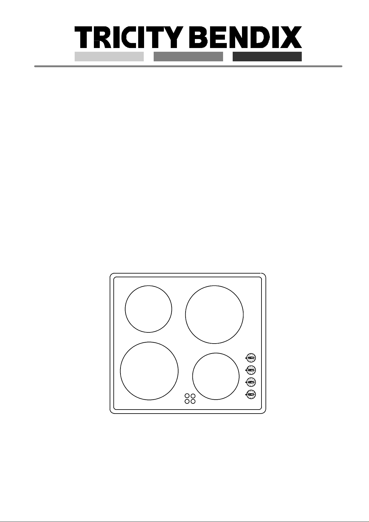
Ceramic Glass Hob
Operating and Assembly Instructions
TBC 650 BL
319 4877-00 PM-D 99.09.24
Page 2

Dear Customer
Thank you for purchasing a Tricity Bendix product.
To enable you to use your appliance effectively and
safely, please read this instruction book carefully
before installing or using the appliance and retain for
futurereference. If yourequire guidancein theuse of the
appliance or require further information, contact our
Customer Care Department.
Customer Care Department
Tricity Bendix
55 -- 77 High Street
Slough
Berkshire
SL1 1DZ
Tel: 08705 950950
Help us to help you
Toregisteryour12monthguarantee, pleasetelephone
us on
0870 606 9876
Page 3

Content
Instructions for the User
Important Safety Information 4
Unpacking and Control 5
Description of the Hob 5
Before the First Use 5
Operating Instructions 6
The Right Cooking Utensils 7
Cleaning and Care 8
Something not Working 9
Service and Spare Parts 9
Customer Care 9
Tricity Bendix Service Force 10
Guarantee Conditions 12
Instructions for the Installer
Technical Data 13
Important Safety Requirements 13
Installation 13
Electrical Connection 15
Page 4

Important Safety Information
ThisSafetyInformationisprovided in the interests of your safety.Pleaseread them carefully before instal lingor using the hob. If you are unsure of the meaning of any of the warnings pleasecontactour Customer
Care Department.
Installation
.This appliance must be installed by qualified per-
sonnel, according to the manufacturer’s instruction
and to the relevant British Standards.
.Remove all packaging before using the appliance.
.Ensure the electrical supply complies with the type
stated on the rating plate.
.Do not attempt to modify the hob in any way.
.Do not install the hob if the ceramic glass is dama-
ged or cracked.
Child Safety
.Thisapplianceis designedto beoperated byadults.
Do not allow children to play near or with the
appliance.
.The appliance gets hot when it is in use. Children
should be kept away until it has cooled.
.Children can also injure themselves by pulling pots
or pans off the hob.
During Use
. Only use the hob when it is fully installed.
. This hob is intended for domestic cooking only. It is
not designed for commercial industrial purposes.
. Ensure the power ON/OFF control is off when not
in use.
. When using other electrical appliances, ensure the
cabledoesnotcomeintocontact with the hot surfaces of the hob.
. Donot useunstableormis-shapenpansonthehob.
. Never leave the hob unattended when cooking with
oil or fat.
. Never use plastic or aluminium foil dishes on the
hob.
. The cooking zones heat up quickly when they are
turned on. Only turn them on when a saucepan is
on the cooking zone.
. The residual heat indicator will not operate if there
is a power failure.
. Incaseapan/pot isleft onthecookingzone theresi-
dual heat indicator can switch off even though the
cooking zone may still be hot from the contents of
the pan.
. Do not store temperature sensitive or inflammable
materials (e.g. detergents, aerosols) in drawers or
cupboards underneath the hob.
. The hob surface must not be used as a storage or
working area.
. Do not allow sugar (solid or liquid) orplastic tocome
into contact with the hob surface when hot.
. Clean this hob in accordance with the Maintenance
and Cleaning Instructions.
. Do not use the hob if the glass is damaged, contact
your local Service Force Centre.
Service
. This hob should only be repaired or serviced by an
authorised Service Engineer and only genuine
approved spare parts should be used.
Disposal
. Please dispose of any packaging material and old
appliances at authorised disposal sites.
Page 5
Unpacking and Control
Pleaseexaminethe appliance before installation. If the appliance is damaged please
immediately contact your retailer before
installation. The packing material should be
disposed of safely, with due regard for the
environment.
Description of the Hob
TBC 650 BL
1 Cooking Zone Ø 180 mm, 1700 W
2 Cooking Zone Ø 145 mm, 1200 W
3 Cooking Zone Ø 180 mm, 1700 W
4 Cooking Zone Ø 145 mm, 1200 W
5. Residual heat indicators
6 Hotplate Switches
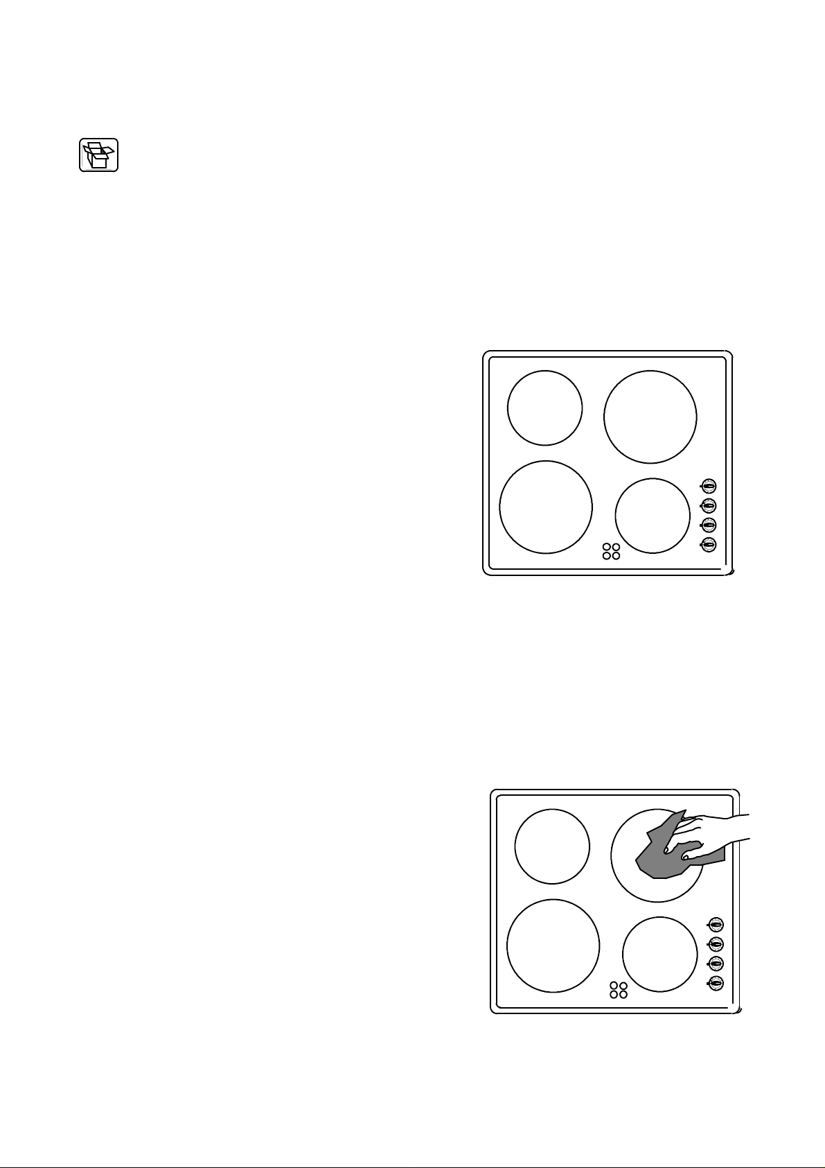
Before the First Use
Cleanyourceramicglasshobthoroughlybeforeitsfirst
use.Thencleanitregularlywhenit is just warm or cold.
Ceramicglass hobs aretreated and cleaned thesame
way as glass.
When you use the ceramic hob for the first time it can
temporarily emit an odour.
2
1
5
3
4
6
Page 6

Operating Instructions
Heat Control Knobs
Thecontrolknobsregulates the heatingcapacityofthe
cooking zones.
The control knobs for the cooking zone can be turned
to the left and to the right to the desired position.
1 = minimum setting
9 = maximum setting.
1
2
3
4
Setting it back to “O“ turns off the cooking zone.
Alwaysputpansorpotsonthehalolightcookingzones,
before switching on.
Hotplate setting chart
Function Examples
OFF
keeping warm,
melting
Gentle simmering
heating
Gentle frying
Simmering
boiling
Frying
Quick frying
2--3
4--5
5--6
6--7
7--8
residual heat, keeping
0
warm
smaller amount of hot
1
pot, sauce, butter ,
chocolate
rice
2
spinach
omelette,
fried eggs
vegetables, small
amounts of fruit with little
liquid
boiled potatoes, stews,
soups, sauces
schnitzel, cutlets, meatballs, fish--filet
in deep fat
potato fritters, pancakes
fried eggs
9
8
5
6
7
Boiling
Deep fat frying
...then switch --back to
9
appropriate setting
Residual heat indicator
Eachcookingzone is relatedto oneindicator. The warning lamp lightsup when the surfaceof the corresponding cooking zone reaches a temperature which could
cause burns.
Thislight remains lit aftertheheated-upareahasbeen
switchedoff as long as the residual heatof the correspondingcookingsurfacecancauseburns.The light will
go out when the temperature falls below 60
o
C.
residual heat indicator
Page 7

The Right Cooking Utensils
Saucepans and frying pans
Saucepansandfryingpansshouldnot be smallerthan
the cookingzone, and preferably not more than 10-15
mm larger than the diameter of the cooking zone.
Always use cooking and frying utensils with smooth,
flat bottoms.
Thebottomsshouldalwaysbe cleananddry.Cookwith
a lid in place.
Checkt hat thebottomsofutensilsaresmothandundamaged; bottoms with burrs and sharp edges will
scratch the ceramic glass surface.
Scratches can also be caused by grains of sand (e.g.
originating from the previous washing of vegetables),
drawn over the cooking surface with the pan, or by
burrs and the rims of pan bottoms.
Toavoidscratchingordamagingtheceramicglasssurface, pots and pans should be moved on the plate by
lifting them, and not by sliding.
Utensilswithaluminiumand copperbottoms can leave
behind metallic discolorations which can only be remnoved with difficulty or sometimes not at all.
When cold, pan bases normally curve slightly inwards
by approx. 0,1-0,5 mm (are concave). In no case
should they curve outwards (be convex).
Followanyguidelinesprovidedbythe saucepanmanufacturer. Ensure they are recommended for use on
ceramic hobs.
Check that the appliance is switched off after
use.
Energy consumption
To save energy, you should . . .
.use only cooking and frying utensils with smooth,
flat bottoms.
.place pots and pans in position before switching in
the cooking zone.
.wherever possible, cover pots and pans with a lid.
8
8
8
8
.switchoff thecookingzoneafewminutesbeforethe
end of thecookingtime, in orderto makeuse of the
residual heat.
.use the residual heat of the cooking zones for kee-
ping food warm or for melting.
.position pots and pans centrally on the cooking
zones.
Page 8

Cleaning and Care
Beforecleaning,makesurethehobiscoolanddisconnected from the power supply.
Never use aggressive or abrasive agents, such
as oven sprays, stain or rust removers, scouring
powder, or sponges with an abrasive effect.
SpecialcleaningagentssuchasVitroclenandceramic
scrapersareavailablefromdepartment stores, electrical specialist shops, and in drug and grocery stores.
Cleaning after each use
. Slight, non-burnt soiling can be wiped off with a
damp cloth.
. Burnt soiling has to be removed with a scraper.
Afterwards wipe off the ceramic glass surface with
a damp cloth, and Vitroclen.
Stain removal
. Light metallic stains (aluminium residues) can be
removedfrom the cookingzonewith a ceramichob
cleaning agent such as Vitroclen when cool.
. Sugar solutions, food stuffs with a high sugar con-
tent, plastics, or kitchen foil - must be removed
immediatelywith ascraper. If this typeof soilageis
not removed immediately it can cause irreparable
damage to the ceramic glass surface. When the
surfacehascooledwipe over with a damp clothand
Vitroclen.
. Before using any detergent or cleaningagent onthe
ceramic glass top, ensure they are recommended
bythe manufacturer for use onceramicglasshobs.
. Do not apply any cleaning agents to hot cooking
zones.Ensureanyresiduesarewipedoff beforethe
cooking zones are used again.
Special problems
if a chemical cleaner proves inadequate. . .. Check whether the use of a scraper is more effective.
when darks stains occur. . .. If the use of a scraper and a stainless steel cleaning
agent proves unsuccessful, your decor surface has
most likely been scratched by using unsuitable cleaning
agents, or by pan bottoms with a scouring effect. This
will not impair the efficiency of your cooking surface.
when metallic discolouration appear on the. . ..
cooking zones
when the surface shows scratches or. . ..
impressions
Pots and pans with unsuitable bottoms, or unsuitable
cleaning agents have been used. The discolouration
can only be removed with considerable effort, using a
ceramic glass or stainless steel cleaning agent.
These blemishes, caused by scraping or melted on
objects, cannot be removed. This will not impair the
efficiency of your cooking surface.
Page 9

Something not working
If yourhob is notfunctioning correctly please carryout
the following checks before calling out an engineer.
Important: If you call out an engineer to a fault
listedbelow, ortorepairafaultcaused byincorrect
use or installation, a charge will be made even if
the appliance is under guarantee.
Symptom Possible Solution
. The cooking zones do not function
. After switching off a cooking zone the hob
hot indicator is not illuminated
. A buzzing is heard when a cooking zone is
switched on
. Discolorations appear in the cooking zone
. Check the mains fuse has not failed
. Check a power level has been selected
. The cooking zone may have only been
switched on for a short while, and is therefore
below 60
o
C
. This is not a fault, the buzzing will disappear
as the zone heats up
. This is probably a result of burned on
remnants that have not been removed
regularly. They will not affect the function of
the hob.
If after carrying out the abovce checks there is still a fault, contact your local Service Force Centre.
Service and Spare P arts
If you require an engineer or you wish to purchase
spare parts contact your local Tricity Bendix Service
Force Centre by telephoning:
08705 929929
Your call will be routed to the Service Centre covering
your post code area. The addresses are listed on the
pages headed Tricity Bendix Service Forces Centres.
When youcontact the Service Centre you will need to
give the following details:
1 Your name, address and post code.
2 Your telephone number.
3 Clear and concise details of the fault.
4 The model and serial number of the appliance
(Found on the rating plate).
5 The purchase date.
In guarantee customer should ensure that the checks
listed in “Something not working“ have been made as
the engineer will make a charge if the fault is not a
mechanical or electrical breakdown.
Customer Care
For general enquiries or for further information on Tricity Bendix products, please contact our Customer
Care Department.
Tricity Bendix
55 -- 77 High Street
Slough
Berkshire
SL1 1DZ
Tel: 08705 950950
Page 10

Tricity Bendix Service Force
To contact your local Tricity Bendix Service Centre telephone 08705 929 929
CHANNEL ISLANDS
GUERNSEY Guernsey Electricity
PO Box 4
Vale, Guernsey
Channel Islands GY1 3AD
JERSEY Jersey Electricity Company
PO Box 45
Queens Road
St Helier
Jersey
Channel Islands JE4 8NY
SCOTLAND
ABERDEEN 54 Claremont Street
(M05) Aberdeen AB10 6RA
AUCHTERMUCHTY 33a Burnside
(M03) Auchtermuchty
Fife KY14 7AJ
BLANTYRE Unit 5
(M07) Block 2
Auchenraith Ind. Estate
Rosendale Way
Blantyre G72 0NJ
DUMFRIES 93 Irish Street
(M01) Dumfries
Scotland DG1 2 PQ
DUNOON Brair Hill
(M67) 7 Hill Street
Dunoon
Argyll PA23 7AL
GLASGOW 20 Cunningham Road
(M04) Clyde Estate
Rutherglen
Glasgow G73 1PP
INVERNESS Unit 3B
(M06) Smithton Ind. Estate
Smithton
Inverness IV1 AJ
ISLE OF ARRAN Arran Domestics
Unit 4 The Douglas Centre
Brodick
(OWN SALES) Isle of Arran KA27 8AJ
ISLE OF BARRA J Zerfah
244 Bruernish
Isle of Barra
(OWN SALES) Western Islands HS9 5QY
ISLES OF BUTE Walker Engineering
(M66) Glenmhor
Upper Serpentine Road
Rothesay
Isle of Bute PA20 9EH
ISLE OF LEWIS ND Macleod
(M69) 16 James Street
Stornoway
Isle of Lewis PA87 2QW
KELSO 2-8 Wood Market
(M08) Kelso
Borders TD5 7AX
ORKNEY Corsie Domestics
(M65) 7 King Street
Kirkwall
Orkney KW15
PERTH Hydro Electrical
Inveralmond House
Ruthervenfield Road
Perth PH1 3AQ
PERTH Graham Begg
Unit 4
Airport Ind Estate
(OWN SALES) Wick KW1 4QS
SHETLAND Tait Electronic Systems Ltd
Lerwick
(OWN SALES) Shetland ZE1 0PW
SHETLAND Bolts Shetland Ltd.
26 North Road
Lerwick
(OWN SALES) Shetland ZE1 0PE
WHALSAY Leask Electrical
Harisdale
Symbister, Whalsay
(OWN SALES) Shetland ZE2 9AA
Holmsgarth Road
NORTHERN IRELAND
BELFAST Owenmore House
(M27) Kilwee Business Park
Upper Dunmury Lane
Belfast
BT17 0HD
CARDIFF Guardian Industrial Estate
(M28) Clydesmuir Road
Tremorfa
Cardiff
CF2 2QS
CLYWD Unit 6-7 Coed – Parc
(M14) Abergele Road
Rhuddlan
Clwyd
Wales
LL18 5UG
DYFED Maes Y Coed
(M77) High Mead
Llanybydder
Carmarthenshire
SA40 9UL
HAVERFORDWEST Cromlech Lodge
(M75) Ambleston
Haverfordwest
Pembrokeshire
SA62 5DS
OSWESTRY Plas Ffynnon
(M17) Warehouse
Middleton Road
Oswestry
SY11 2PP
WALES
NORTH EAST
GATESHEAD Unit 356a
(M39) Dukesway Court
Dukesway
Team Valley
Gateshead NE11 0B H
GRIMSBY 15 Hainton Avenue
(M42) Grimsby
South Humberside
DN32 9AS
HULL Unit 1
(M41) Boulevard Industrial Estate
Hull
HU3 4AY
LEEDS 64-66 Cross Gates Road
(M37) Leeds
LS15 7NN
NEWTON AYCLIFFE Unit 16
(M45) Gurney Way
Aycliffe Industrial Estate
Newton Aycliffe
DL5 6UJ
SHEFFIELD Pennine House
(M38) Roman Ridge Ind. Est
Roman Ridge Road
Sheffield S9 1GB
NORTH WEST
BIRKENHEAD 1 Kelvin Park
(M11) Dock Road
Birkenhead
L41 1LT
CARLISLE Unit 7
(M10) James Street Workshops
James Street
Carlisle
Cumbria CA2 5AH
ISLE OF MAN South Quay Ind. Estate
(M64) Douglas
Isle of Man
IM1 5AT
LIVERPOOL Unit 1
(M15) Honeys Green Precinct
Honeys Green Lane
Liverpool
L12 9JH
MANCHESTER Unit B
(M09) Central Industrial Estate
St Marks Street
Bolton
BL3 6NR
PRESTON Unit 250
(M13) Dawson Place
Walton Summit
Bamber Bridge
Preston
STOCKPORT Unit 20 Haigh Park
(M16) Haigh Avenue
Stockport
SK4 1QR
Lancashire PR5 8AL
Page 11

Tricity Bendix Service Force
To contact your local Tricity Bendix Service Centre telephone 08705 929 929
MIDLANDS
BIRMINGHAM 66 Birch Road East
(M18) Wyrley Road Ind. Estate
Witton
Birmingham
B6 6DB
BOURNE Manning Road Ind. Estate
(M44) Pinfold Road
Bourne
PE10 9HT
BRIDGNORTH 68 St. Mary’s Street
(M72) Bridgnorth
Shropshire
WV16 4DR
GLOUCESTER 101 Rycroft Street
(M23) Gloucester
GL1 4NB
HEREFORD Unit 3
(M31) Bank Buildings
Cattle market
Hareford
HE4 9HX
HIGHAM FERRERS 30 High Street
(M51) Higham Ferrers
Northants
NN10 8BB
ILKESTON Unit 2
(M43) Furnace Road
Ilkeston DE7 5EP
LEICESTER Unit 7
(M22) Oaks Ind. Estate
Coventry Road
Narborough
Leicestershire
LE0 5GF
LINCOLN Unit 8
(M40) Stonefield Park
NEWCASTLE 18-21 Croft Road
UNDER LYME Brampton Ind. Estate
(M12) Newcastle under Lyme
Staffordshire
ST5 0TW
REDDITCH 13 Thornhill Road
(M20) North Moons Moat
Redditch
Worcestershire
B98 9ND
TAMWORTH Unit 3
(M19) Sterling Park
Claymore
Tamworth
B77 5DO
WORCESTER Units 1 & 2
(M73) Northbrook Close
Gregorys Mill Ind. Estate
Worcester
WR3 8BP
Clifton Street
Lincoln
LN5 8AA
LONDON & EAST ANGLIA
BECKENHAM 11a Gardener Ind. Estate
(M79) Kent House Lane
Beckenham
Kent BR3 1QZ
CHELMSFORD Hanbury Road
(M47) Widford Ind. Estate
Chelmsford
Essex
CM12 3AE
COLINDALE Unit 14
(M53) Capitol Park
Capitol Way
Colindale
London NW9 0EQ
ELTHAM 194 Court Road
(M78) Mottingham
Eltham
London SE9 4EW
ENFIELD 284 Alma Road
(M49) Enfield
London
EN3 7BB
GRAVESEND Unit B4
(M57) Imperial Business Estate
Gravesend
Kent
DA11 0DL
HARPENDEN Unit 4
(M46) Riverside Estate
Coldharbour Lane
Harpenden
AL5 4UN
LETCHWORTH 16-17 Woodside Ind. Estate
(M50) Works Road
Letchworth
Herts
SG6 1LA
LONDON 2/4 Royal Lane
(M76) Yiewsley
West Drayton
Middlesex
UB7 8DL
MAIDENHEAD Reform Road
(M60) Maidenhead
Berkshire
SL6 8BY
MOLESEY 10 Island Farm Avenue
(M61) West Molesey
Surrey
KT8 2U Z
NEWBURY 9 Pipers Court
(M24) Berkshire Drive
Thatcham
Berkshire
RG19 4ER
IPSWICH Unit 6C
(M48) Elton Park Business Centre
Hadleigh Road
Ipswich
IP2 0DD
NORWICH 2b Trafalgar Street
(M52) Norwich
NR1 3HN
SUNBURY Unit 1a
(M63) The Summit
Hanworth Road
Hanworth Ind. Estate
Sunbury on Thames
TW16 5D
ASHFORD Unit 2
(M58) Bridge Road Business Est.
Bridge Road
Ashford
Kent TN2 1BB
FLEET Unit 1
(M59) Redsfield Ind. Estate
Church Crookham
Fleet
Hampshire GU13 0RD
HAYWARDS 21-25 Bridge Road
HEATH Haywards Heath
(M55) Sussex RH16 1UA
BARNSTAPLE Main Road
(M30) Fremington
Barnstaple
North Devon EX31 2NT
BOURNEMOUTH 63-65 Curzon Road
(M26) Bournemouth
Dorset
BH1 4PW
BRIDGEWATER 6 Hamp Ind. Estate
(M35) Bridgewater
Somerset TA6 3NT
BRISTOL 11 Eldon Way
(M25) Eldonwall Trading
Bristol
Avon BS4 3QQ
EMSWORTH 266 Main Road
(M33) Southbourne
Emsworth
PO10 8JL
ISLE OF WIGHT Unit 8
(M34) Enterprise Court
Ryde Business Park
Ryde
Isle of Wight PO33 1DB
NEWTON ABBOT Unit 2
(M29) Zealley Ind. Estate
Kingsteignton
Newton Abbot
S. Devon
TQ12 3TD
REDRUTH Unit 7D
(M36) Pool Ind. Estate
Wilson Way
Redruth
SOUTH EAST
SOUTH WEST
Cornwall TR15 3QW
Page 12

Guarantee Conditions
Standard guarantee conditions
We, Tricity Bendix, undertake that if within 12 months
ofthedateof thepurchasethisTricity Bendixappliance
or any partthereof is provedto be defective by reason
only of fault workmanship or materials, we will, at our
option repair or replacethe sameFREE OF CHARGE
for labour, materials or carriage on condition that:
Theappliancehasbeencorrectlyinstalledandused
only on the electricity supply stated on the rating
plate.
The appliance has been used for normal domestic
purposes only, and in accordance with the manufacturer’s instructions.
The appliance has not been serviced, maintained
repared, taken apart or tampered with any person
not authorised by us.
All service work under this guarantee must be
undertakenby an TricityBendixServiceForceCentre.
Any appliance or defective part replaced shall
become to Company’s property.
This guarantee is in addition to your statutory and
other legal rights.
Home visits are made between 8.30 am and 5.30 pm
Monday to Friday. Visits may be available outside
these hours in which case a premium will be charged.
European Guarantee
If you should move to another country within Europe
thenyourguaranteemoves with you toyournewhome
subject to the following qualifications:
The guarantee starts from the date you first purcha-
sed your product.
The guarantee is for the same period and to the
same extent for labour and parts as exists in the
new country of use for this brand or range of products.
This guarantee relates to you and cannot be trans-
ferred to another user.
Your new home is within the European community
(EC) or European Free Trade Area.
The product is installed and used in accordance
with ourinstructions andis only used domestically,
i.e. a normal household.
The product is installed taking into account regula-
tions in your new country.
Before you move please contact your nearest Customer Care Centre, listed below, to give them details of
your new home. They will then ensure that the local
Service Organisation is aware of your move and able
to look after your appliances.
Exclusions
This guarantee does not cover:
Damage or calls resulting from transportation,
improper use or neglect, the replacement of any
light bulbs or removable parts of glass or plastic.
Coasts incurred for calls to put right an appliance
which is improperly installed or calls to appliances
outside the United Kingdom.
Appliances found to be in use within a commercial
environment,plusthosewhich aresubjectedtorental agreements.
Products of Tricity Bendix manufacture which are
not marketed by Tricity Bendix.
France Senlis +33 (0) 3 44 62 22 22
Germany Nürnberg +49 (0) 911 3232 2600
Italy Pordenone +39 (0) 1678 47053
Sweden Stockholm +46 (0) 20 78 77 50
UK Slough +44 (0) 1753 219 898
Page 13

Instructions for the Installer
Please examine the appliance for any damage. If the
appliance is damaged contact your retailer before the
appliance is connected.
Please keep packaging away from children and dispose of with due regard for the environment.
Technical Data
TBC 650 BL
Hob dimensions:
length: 572 mm
depth: 502 mm
height: 49 mm
Cut out dimensions:
length: 560 mm
depth: 490 mm
Voltage 230 V - 50 Hz
Cable 6 mm
Total power: 5,8 kW
Fuse rating 30 Amp
We reserve the right to make technical changes.
Important Safety Requirements
.The hob must only be installed by a qualified electri-
cian.
.Damaged hobs with cracks or breakages in the
ceramicglasssurface must not be connectedto the
electrical supply.
MADE IN GERMANY
TYP: PEE2 001 PNC: 949 590 770 MODEL: TBC 650 BL
AC 230 V
Total max. 5.8 kW
F.Nr.: . . . . . . . . . . . .
.This hob must be installed in accordance with the
IEE Wiring Regulations (current Edition). Detailed
recommendations are contained in the following
British Standards Codes of Practice: B.S.
6172/B.S. 5440 Part 2 and B.S. 6891 CurrentEditions.
Installation dimensions
The opening in the cabinet must correspond to the
standard dimensions. The necessary information can
be found in the dimensional sketch.
.The separation between the lower surface of the
hob and the parts of the furniture below it must be
at least 20 mm
.The lateral separation between the sides of the hob
and the cabinet must be at least 55 mm, and must
be at least 55 mm from the rear panel.
distance from worktop
opening to the rear wall
min 55 mm
20 mm
distance from worktop opening to
the left or right side wall or to a high cupboard
min 55 mm
20 mm
Page 14

.The minimum distance combustiblematerial canbe
fittedabovethehobinlinewiththeedgesofthehob
is420 mm. Ifit is fittedbelow420mm a spaceof55
mm must be allowed from the edges of the hob.
.The minimum distance combustiblematerial canbe
fitted directly above the hob is 700 mm.
.If a cooker hood is installed above the hob, a clea-
rance height of 650 mm must be allowed.
This appliance conforms to Type Y (IEC 335-2-6)
with regard to fire protection. Only appliances of
this type may be installed on one side of adjacent
cabinets or walls.
Installation
.Cut the worktop according to the prescribed dimen-
sions.Seefig.1.Sawexactlyalongthescribedline.
.Place according to figure 2.
Fastening according to fig. 3
.Tighten bracket against the underside of the work-
top. Fix according to figur 3.
.Using a screwdriver, tighten the tension clamps
evenlystarting at the centre andmoving diagonally
until the built-in rim is tight on the worktop.
.Do not over tighten.
.Do not use an electric or pneumatic screwdriver
without an adjustable safety clutch.
fig 1
radius
Points for fixing clamps
fig 2
R5
min. 650 mm
width
560 + 1
490 + 1
depth
R5
radius
fig 3
+1
worktop
fixing clamp
hobs frame
490 +1560
Ceramic glassplate
Einbaukasten
Page 15

Electrical connections
Before connecting the appliance, check that the voltagequotedon the ratingplate-thatis,thenominalvoltage of the appliance - corresponds to the available
mains voltage. The rating plate can be found on the
lower housing of the ceramic glass hob.
Mains terminal
in the bottom of the hob
Themainsconnectionmust be carriedoutbyanexpert
electrician. The VDE-regulations and the valid prescriptions by the localpower suppyboards have to be
compiled with.
Prior to connection it should be checked whether the
voltage stated on the type plate -- i.e. the nominal voltage of the appliance and of the oven/control box -- is
identical with the prevailing mains voltage. The type
plate ist located on the hobs bottom.
The heating elementvoltage amounts to 230 V ~. The
appliance will also perfectly perform with the former
mains voltage of 220 V ~.
Themainsconnectionmust be carriedoutinawaythat
an all--pole insulating device is existing with a contact
opening of at least3 mm, e.g. LS--automatism, earth-leakage circuit--breaker or fuse.
A wire of typeH05VV-F orofhigherratingistobeused
as supply cable.
The mains terminal is located in the bottom of the
appliance behind a covering slide. It can be opened
with a screw driver (pict.).
changing bridges of the terminal
strain relief device
Connecting possibilities
1 2 3 4
5
3 x 6 mm
2
(30 A)
According to existing mains voltage the appliance has
to be connected in correspondence with the diagrams
of connectingpossibilities. The bridgesof the terminal
board are to be changed accordingly, if need be.
Theprotectiveconductoris to beconnectedtoterminal
. The protective conductor must be longer than live
leads.
The cable connections have to be established as
prescribed and the terminal screws be firmly
tened.
Afterwardsthesupplycablehasto besecuredbystrain
relief device and the covering slide must be closed by
firmly pressing down (until it enganges).
Prior t o first use remove any possibly existing labels
and protective film from the ceramic glass plate or the
frame of the hob.
After connectingthe electrical supply, all cooking
zonesshould be brieflyswitched on one after the
other at their maximum power, in order to test
whether they are operational.
tigh-
L1 N
L1 L2 N
L1 L2 L3 N
(L3)
L1 L2
L1 L2 L3
230 V ~
1 L + N
51 2 3 4
4 x 2,5 mm
(20 A)
400 V 2 N ~
2
2 L + N
51 2 3 4
5 x 2,5 mm
(16 A)
400 V 3 N ~
2
3 L + N
51 2 3 4
3 x 4 mm
(32 A)
230 V 2 ~
2
2 L
51 2 3 4
4 x 2,5 mm
(20 A)
230 V 3 ~
2
3 L
Page 16

IBNr.319 4877-00
99.09.24 PM--D
 Loading...