

Page 1
206 Rev 3 Jan 2019
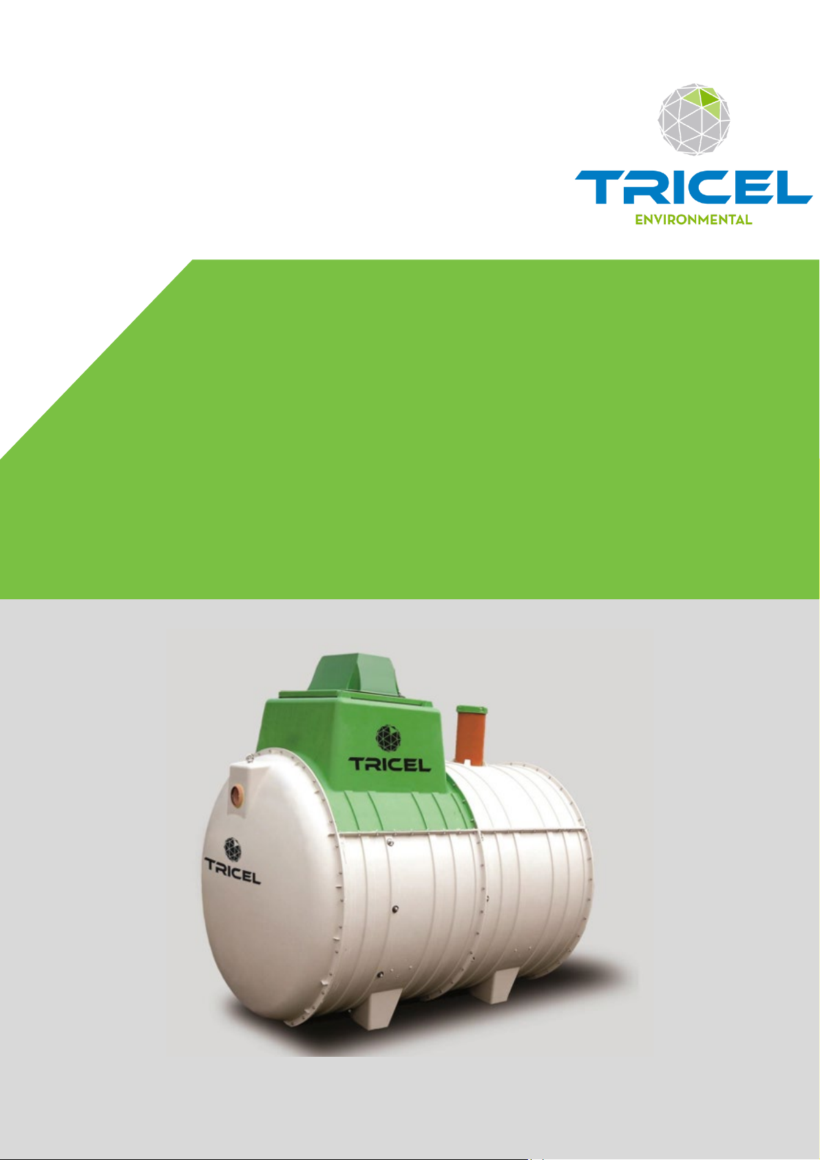
Tricel® Vitae UK6
Wastewater Treatment Plants
Engineering a green future
1
Page 2
Contents
1 Health & safety precautions ...................................................................................................... 4
1.1 General .............................................................................................................................. 4
1.2 Electrical maintenance ...................................................................................................... 4
1.3 Installation ........................................................................................................................ 5
2 Introduction: Tricel Vitae ........................................................................................................... 6
2.1 The Wastewater purification process ................................................................................ 6
Stage 1: Buffer chamber ................................................................................................ 6
Stage 2: Aeration (treatment) chamber ......................................................................... 6
3 Tricel Vitae specification ........................................................................................................... 7
3.1 Dimensions ....................................................................................................................... 7
3.2 Tank drawing ..................................................................................................................... 8
4 Transportation & lifting ............................................................................................................. 9
4.1 Transportation .................................................................................................................. 9
4.2 Lifting ................................................................................................................................ 9
5 Installation
5.1 Installation planning ....................................................................................................... 11
5.2 Inspection on reception of tanks ..................................................................................... 12
5.3 Positioning and precautions ............................................................................................ 12
5.4 Types of installation........................................................................................................ 12
5.5 Installation procedure: Tricel Tanks ................................................................................ 13
............................................................................................................................. 11
Excavation (dry & wet sites): ....................................................................................... 13
Step by step – installation procedure .......................................................................... 15
5.6 Gravel specification ........................................................................................................ 16
5.7 Concrete specification .................................................................................................... 17
5.8 Topsoil requirements ...................................................................................................... 17
5.9 Electrical requirements ................................................................................................... 17
5.10 Risers .............................................................................................................................. 18
5.11 Non-standard .................................................................................................................. 18
Alternative to concrete backfill (for wet sites without risers only):
................... 18
Sloping ground: ....................................................................................................... 19
Proximity to rolling & static loads: .......................................................................... 19
5.12 Additional accessories .................................................................................................... 20
Grease trap .............................................................................................................. 20
Sampling chamber ................................................................................................... 20
6 Capsule installation ................................................................................................................. 21
2
Page 3

7
Commissioning ........................................................................................................................ 21
7.1 Control panel start-up ..................................................................................................... 22
7.2 Operation of the control panel ........................................................................................ 24
Basic screen display..................................................................................................... 24
Start-up phase ‘Start 150%.’ ....................................................................................... 25
8 Disposal of treated water ........................................................................................................ 26
9 Maintenance ............................................................................................................................ 26
9.1 Regular maintenance ...................................................................................................... 26
9.2 Annual maintenance........................................................................................................ 26
9.3 Annual service (available from your supplier) ................................................................. 27
9.4 Production of sludge ....................................................................................................... 27
9.5 Desludging (emptying the solid waste from the primary chamber) ................................ 27
10 Operating conditions .......................................................................................................... 28
11 Troubleshooting.................................................................................................................. 30
11.1 Odours ............................................................................................................................. 31
12 Certification ........................................................................................................................ 32
12.1 Declaration of performance ............................................................................................ 32
13 Terms & conditions ............................................................................................................. 36
3
Page 4
1 Health & safety precautions
Precaution
Reading the full technical manual prior to installation is important. Retain this document for the
lifetime of the product and in the event of a change of ownership of the site, transfer to the new
owner.
1.1 General
As health and safety are of vital importance, the following aspects are critical:
Prior to installing, please consider the finished garden level. If you envisage that a
manhole riser/extension may be required to ensure manhole cover remains above finished
ground level, the plant must be installed with the appropriate excavation foundation and
backfill to accommodate the riser. Please refer to section 5.10, ‘Risers.’
•
It is important that all of the information contained in this manual be adhered to at
all times.
•
Treated wastewater is not suitable for human consumption.
•
It is important that locks be fitted to the manhole cover to prevent accidental access.
•
Manholes are rated to 125kg and are for pedestrian use only.
•
Never enter a tank unless qualified to do so.
•
Do not use naked flames in the vicinity of the tank due to the danger of combustion.
•
The manhole covers shall never be left off of an unattended tank. Always lock the
covers of the plant when work gets completed.
•
Sewage and sewage effluent can carry micro-organisms and gases harmful to human
health. Any person carrying out work on the
•
Suitable protective clothing; including gloves, goggles should be worn at all times.
Always remove contaminated clothing and protective equipment after working with
sewage treatment plants. Wash hands and face prior to eating, drinking or smoking.
•
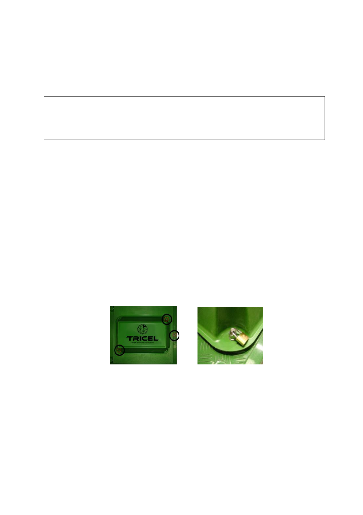
Lock all manhole covers for safety. Tanks are supplied with three locking points, as
shown below. All points should be locked with a suitable locking device to prevent
unauthorised access. Locks do not come supplied.
Vitae
must be appropriately trained.
1.2 Electrical maintenance
•
All electrical work is to be carried out by a qualified electrician using suitable
materials for the application.
• Do not open the Tricel Vitae’s electrical unit cover without firstly isolating the mains
power.
Electrical work must be carried out strictly to the manufacturer’s instructions and to
•
the relevant national rules for electrical installations.
•
When working with machinery/electrical equipment, the proximity of water shall be
noted. Electrical
•
There is the potential danger of falling into the tank during desludging while manholes
may be open – take all necessary safety precautions when desludging.
equipment shall not be wet when working with it.
4
Page 5

1.3 Installation
•
Plan excavation work with due regard to health and safety requirements.
•
Excavated material should either be shored or battened back to a “safe” angle.
•
Use appropriate lifting equipment.
•
Take care around grounds work machinery.
•
Keep proper footing and balance at all time.
• It is necessary to vent the Tricel Vitae at the inlet and the outlet of the plant.
5
Page 6
2 Introduction: Tricel Vitae
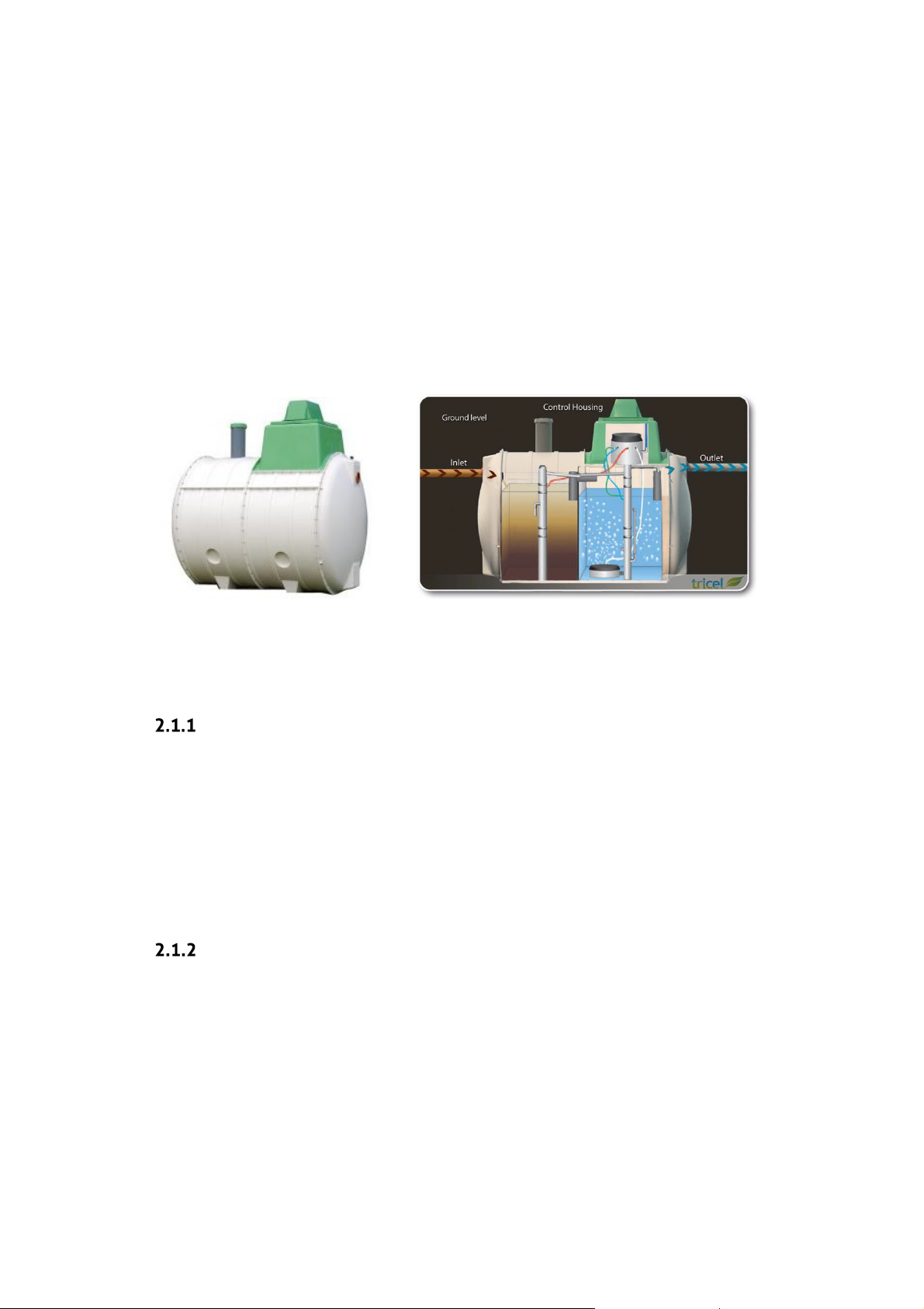
Tricel Vitae wastewater treatment plants are manufactured from sheet moulding compound (SMC)
ensuring a durable and high-strength product. They are also constructed from modular
components; these modules are then fabricated together to make different size tanks.
The Tricel Vitae is suitable for domestic and light commercial applications and is a sequential batch
reactor (SBR). There are two zones in the SBR treatment system. The first is a buffer zone where the
wastewater gets stored. From here it is carried into the second zone for treatment in batches.
Wastewater is then treated for a set amount of time, after which it is expelled from the tank. As the
treatment is for a fixed amount of time in each batch, the water emitted from the tank is to the
highest quality standard even in times of high usage
.
2.1 The Wastewater purification process
Stage 1: Buffer chamber
The buffer chamber acts primarily as a storage zone to hold the wastewater until it is ready to be
treated. This ensures that even in times of low usage there is a constant supply of wastewater to
feed the bacteria. While being stored the heavy solids settle to the bottom of the tank and the light
particles, like fats or oils, float to the top of the water to create a scum. An airlift pump takes
wastewater from the buffer chamber to the aeration chamber in batches at the beginning of the
aeration cycle. The airlifter is designed to ensure that only the wastewater from the centre of the
chamber gets transferred into the aeration chamber.
Stage 2: Aeration (treatment) chamber
This stage of the process takes place in the second chamber where submerged aeration combines
the principles of the biofilm and activated sludge processes. Masses of naturally occurring bacteria
form in clumps at the bottom of the chamber. These bacteria get sustained with air delivered by
means of an aerator at the bottom of the tank which turns on intermittently throughout the cycle.
After the aeration takes place, there is a settling phase in which the aerator is turned off for 1.5 -2
hours. This process allows for the solids and the bacteria to settle to the bottom of the chamber. As
a result, the water above is cleared of any solid particles before it gets expelled from the tank.
6
Page 7
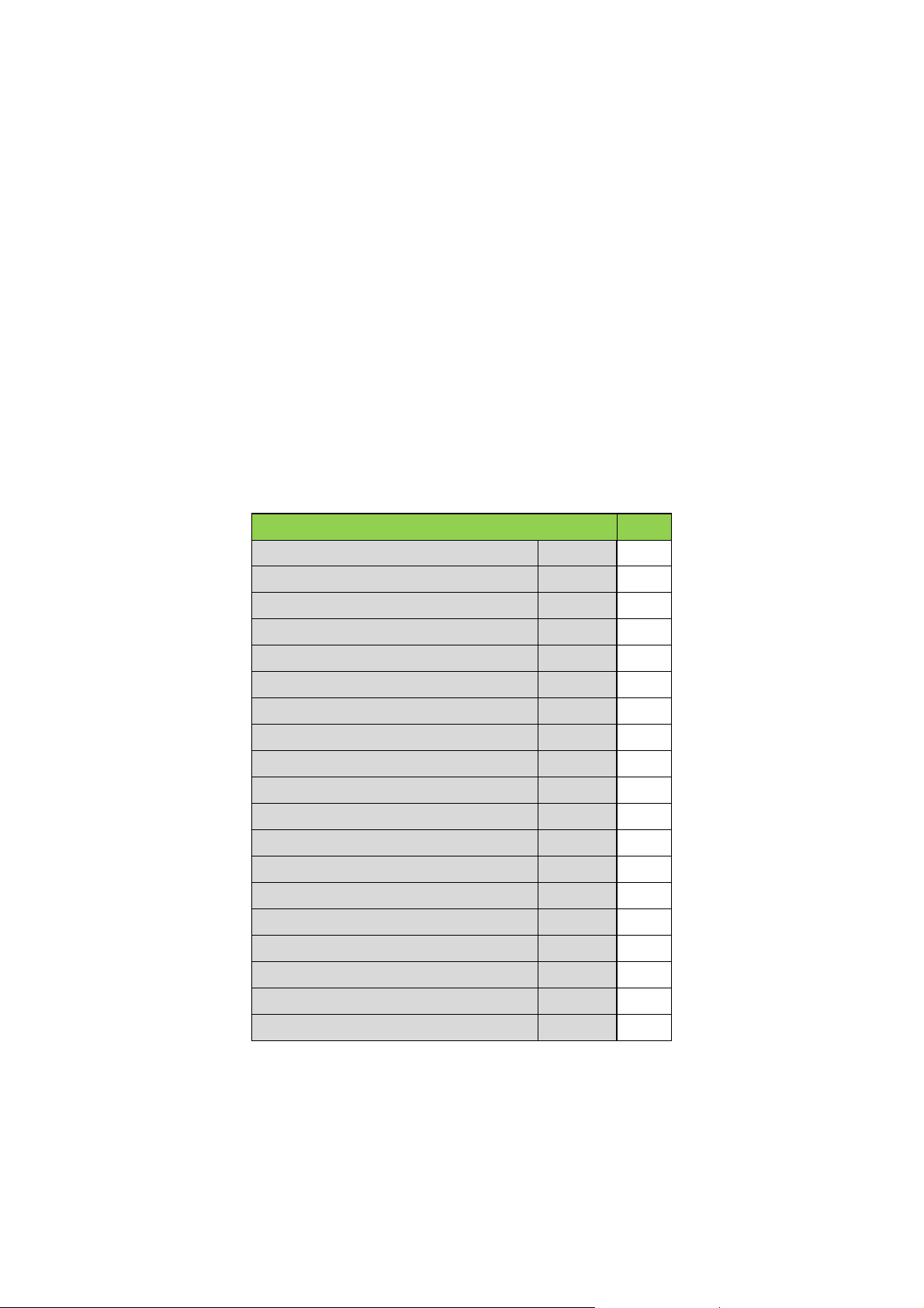
During the settlement phase, the batch of liquid is kept in this chamber for a set amount of time
Tricel Vitae
UK6
Maximum treatment capacity
PE 6 Design flow rate (max)
litres/day
900
BOD load (max)
kg/day
0.36
Primary chamber volume
litres
2630
Nominal Inlet pipe diameter
mm
110
Nominal Outlet pipe diameter
mm
110
Overall length
m
2.6
Overall width
m
1.64
Overall height
m
2.24
Inlet invert to base
m
1.4
Outlet invert to base
m
1.3
Inlet invert to ground level
m
0.51
Outlet invert to ground level
m
0.61
Weight empty**
kg
300
No. of persons
1-6
Air blower rating (mean)
W
86
Thickness (minimum)
mm
5
Desludge period (minimum)***
year
1.5 – 3
No. of Diffusers
Units
1
and then expelled from the tank using the clearwater lifter. Simultaneously, the excess sludge
lifter recirculates the excess sludge from the tank back to the primary chamber. Doing so ensures
that there is a constant level of sludge in the primary chamber to feed into the aerated zone.
The clearwater enters the sampling pot before leaving the tank. Doing so allows for the water to
get tested for purity. The remaining treated liquid now meets the required standard to be safely
passed out of the Tricel Vitae unit.
3 Tricel Vitae specification
3.1 Dimensions
Tricel Vitae: certified to EN 12566-3:2005
** Allow 100kg extra for lifting purposes
*** Depending on use & design value
7
Page 8
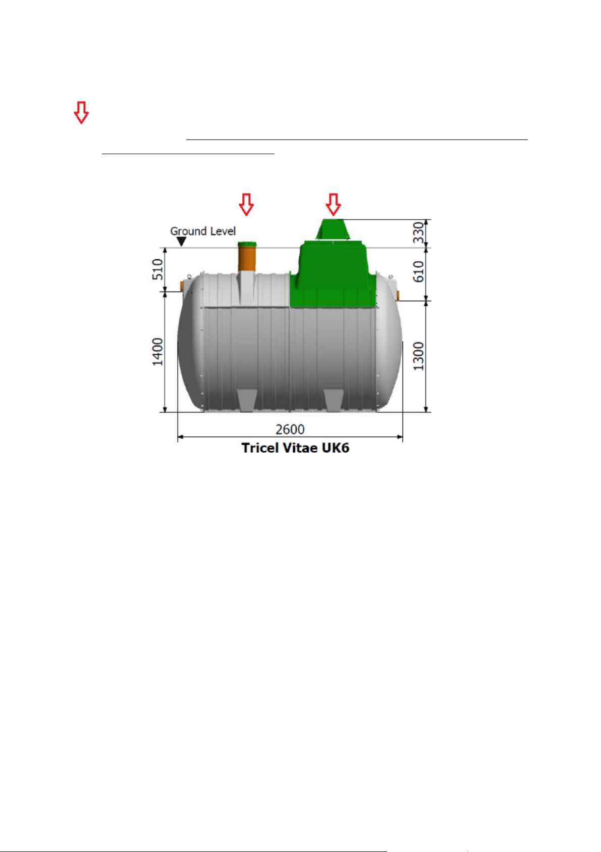
3.2 Tank drawing
The arrow indicates an access point which must be opened to facilitate the desludging of the
primary chamber. However, do not desludge the reactor/aeration chamber as this will affect
the treatment efficiency of the plant.
WARNING: care must be taken not to damage pipework when desludging the tank
8
Page 9
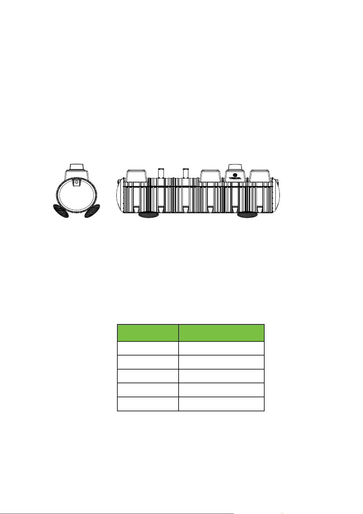
4 Transportation & lifting
Length of tank
Minimum length of the
sling
2.1
2.1
2.6
2.6
3.1
3.1
3.6
3.6
4.6
4.6
4.1 Transportation
• Tanks must be held down during transportation using nylon straps, do not use cables or
chains to secure tanks. Do not over tighten straps that can result in deformation of the
tank shell. Do not drop or roll tanks from the truck.
• Move tanks only by lifting and setting, do not drag or roll.
• Always set the tank(s) on flat, smooth ground clear of debris. In order to prevent
movement, tanks may need to be tied down and chocked. Position the chocks in the
locations shown below:
4.2 Lifting
• A machine and webbing lifting straps best lift tanks – do not use chains or wire ropes in
contact with the tank.
• Ensure tank is empty when lifting.
• Tanks from one to four modules (4.6m) in length should be lifted using the eyebolts on
the tank. Ensure the angle between the slings is not greater than 60o when lifting the
tank. In order to ensure the angle is not greater than 60o the following sling lengths
are required:
9
Page 10
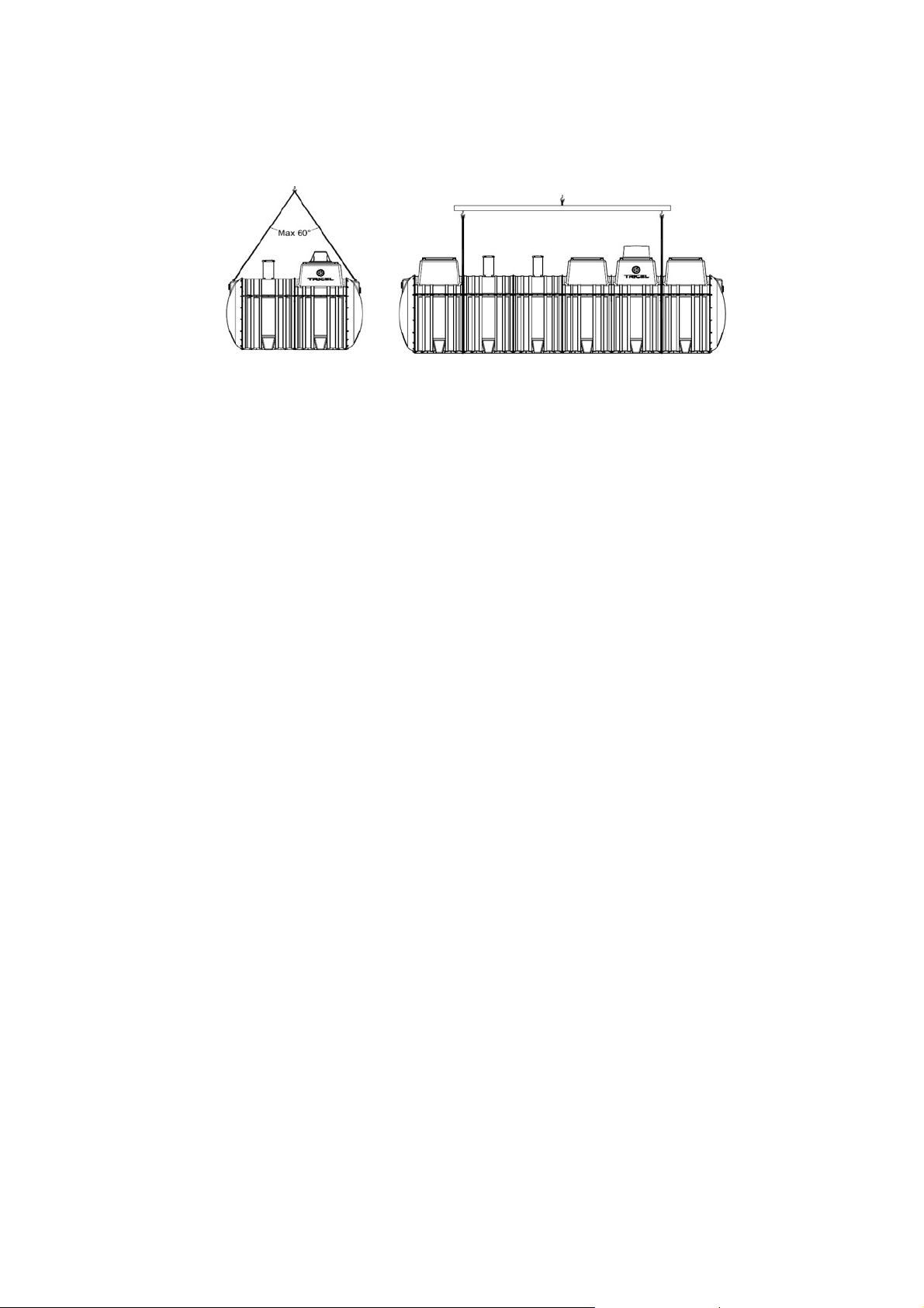
Ensure sufficient lifting height can be achieved and is available on site. If not a lifting bar, as per
option two below, is required.
Option 1 Option 2
10
Page 11

5 Installation
Important
Before the installation of the Tricel Vitae, it is important to read these instructions carefully.
5.1 Installation planning
• When planning the installation of a Tricel Vitae, you must consider the following:
Backfill considerations:
o Is this a dry or wet site, i.e. the presence of a water table?
o Which backfill material is appropriate for this site?
o What will the finished ground level be and will risers be required?
Site considerations:
o Is the site restricted regarding area or height?
o What is the topography of the site, i.e. being it sloping or flat?
o What is the proposed depth of the installed tank to ensure the required slope
upstream?
o Are static or rolling loads present on this site?
• Only suitably qualified personnel should install the Tricel Vitae.
• Suitably sized equipment will be required to excavate the hole and to lift the
into place.
Vitae
Tricel
11
Page 12

5.2 Inspection on reception of tanks
•
Visually inspect tanks for damage or fractures to the shell or ribs, de-laminations,
scratches, or abrasions deeper than 1.5mm, which may have occurred during transport,
prior to installation. Notify the delivery driver and/or your supplier of any found. Do not
attempt to carry out any unauthorised repairs, as this will invalidate the warranty on the
tank.
Once installed, Tricel cannot accept any claims for damage to the tank.
•
5.3 Positioning and precautions
• The Tricel Vitae should not get installed in an area subject to flooding or excessive water
runoff as no flood waters should enter the tank.
• The area around the Tricel Vitae should be adequately drained to permanently remove
groundwater and surface water from proximity to the tank.
• The Tricel Vitae is not suitable to be used in water-logged sites where the groundwater
may rise above the inlet pipe.
• When selecting the location of the Tricel Vitae, ensure that it is always accessible for future
maintenance.
• The Tricel Vitae must be vented at the outlet and the inlet of the plant.
5.4 Types of installation
All installations must be “fit for purpose” to suit the on-site conditions, which will vary from site
to site. Ensuring this is the responsibility of the on-site contractor.
When installing a Tricel Vitae, there are two types of standard installation methods:
1. Gravel installation
2. Concrete installation
It is essential to consider two factors when determining which installation must be implemented:
1. Is the Tricel Vitae being installed in a ‘dry site’ or a ‘wet site’?
• A ‘dry site’ is a site in which the water table never rises higher than the base of
the tank.
• A ‘wet site’ is a site in which the water table may rise higher than the base of
the tank but will not climb higher than the invert of the inlet. Where a higher
water level is present on site, ensure that the installation is suitable for the site
conditions.
Tricel
strongly advises the installation of a vertical water table inspection pipe.
This inspection pipe will facilitate convenient monitoring of the water table
long after the installation is complete.
Note: In difficult soils (e.g., clay with a high t-value), a site could be potentially
classified as wet if there is no drainage for surface water that enters the
12
Page 13
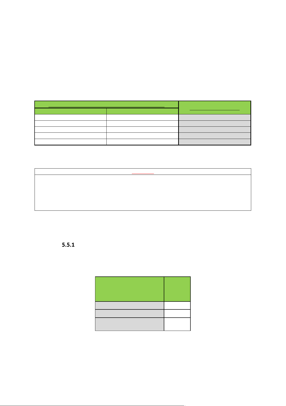
excavation and it rises higher than the base of the tank. The installer must
Factors that determine the required installation
Type of site
Riser required
Dry
None
Gravel
Dry
250mm
Gravel
Dry
500mm & 750mm
Concrete
Wet
None
Concrete
Wet
250mm, 500mm & 750mm
Concrete
Important
•
Incorrectly installed tanks that are subject to movement, rotation, excessive loading
•
Ballasting the tank is essential to avoid the tank from lifting when backfilling.
determine this when selecting the correct backfill.
2. Is a riser required (inlet invert >510mm from ground level), and if yes, what height riser
is necessary? (For more information on risers, please refer to section 5.10, ‘Risers’).
The following table specifies the required installation for on-site conditions:
Installation required
or floatation may become damaged, for which Tricel cannot accept liability.
•
During installation, tanks must not be subjected to buoyant forces.
•
Contact a qualified engineer if there are difficulties on site due to adverse
waterlogging.
5.5 Installation procedure: Tricel Tanks
Excavation (dry & wet sites):
5.5.1.1 Excavation: length & width
Length and width of the excavation must exceed the dimensions of the
500mm to maintain a minimum space of 250mm all around the tank.
Tricel Vitae UK6
Tank length (m)
Tank width (m)
Excavation size (L x W) (m)
2.6
1.64
3.1 x
2.14
Tricel Vitae
by at least
Note: The size of the area for excavation applies to both dry and wet sites. However,
ground including regions with excessive sand, peat swamps, etc., may require larger
excavations. The excavation should be maintained dry by pumping or whatever suitable means.
unstable
13
Page 14
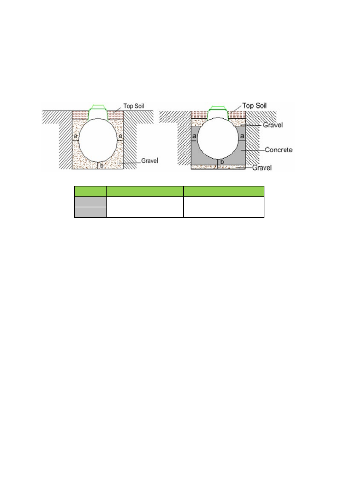
5.5.1.2 Excavation: depth
“a” minimum (mm)
“b” minimum (mm)
Dry site
250
250
Wet site
250
300
The inlet and outlet pipes determine the excavation depth, invert levels are relative to the
bottom of the tank and allowing for the minimum base thickness. Dimension details of the tank
provided on the relevant drawing; please refer to section 3, ‘Tricel Vitae Specification.’ Ground
instability, e.g. running sand may necessitate over-excavation and stabilisation with hard core
or blinding concrete. The standard depth of the excavation for both gravel and concrete
installations are outlined as follows:
14
Page 15
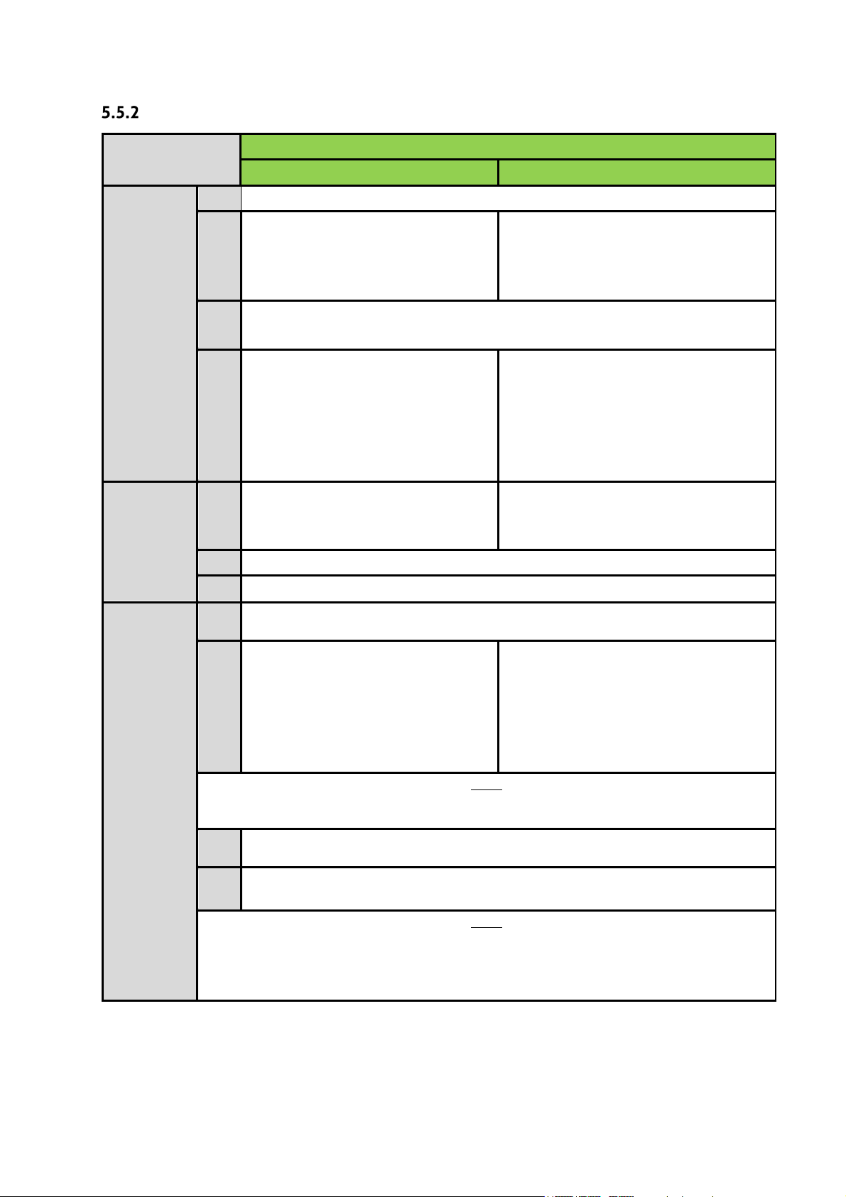
Step by step – installation procedure
Installation required (post-excavation)
Gravel
Concrete
Remove any soft spots or large stones and boulders.
The base is constructed of a 250mm
The base is constructed of a 50mm layer
Ensure that base is level and at the correct height to accommodate the
It is important to maintain a completely
Mechanically lift the plant carefully
Mechanically lift the plant carefully
The plant must sit level on the base.
Connect and seal the pipework to the tank.
Ballast the plant by filling each chamber with clean water to a depth of 300mm
and recheck the pipework levels.
Commence backfilling with gravel in
Commence backfilling with concrete in
Note
water level is no more than 300mm above the backfill level.
Mount and seal manhole risers (if required). Please refer to section 5.10,
‘Risers.’
Complete backfilling with topsoil up to the max ground level. Allow for
Note
gravel backfill.
Steps
1
Installation
of the tank
base:
How to
position the
tank on to
the base:
layer of suitably compacted gravel.
2
3
4
into the centre of the hole and place
5
6
7
8
on the prepared base.
of suitably compacted gravel, covered
with a 250mm layer of semi-dry
concrete.
incoming pipework.
dry excavation until the final pour of
concrete is set. It may be necessary to
line the excavation with a continuous
layer of 1200-gauge polythene to
maintain the integrity of the concrete.
into the centre of the hole.
layers of 225mm evenly around the
tank ensuring that there are no voids
until gravel has reached 50mm over
9
Compact each layer in succession. *
Backfilling
around the
tank:
* Continue filling the chambers with water while backfilling, ensure that the rising
10
11
The use of geotextile barrier fabrics over the gravel backfill is considered good
installation practice. The fabric must be chosen to allow the flow of water in and
out of the excavation but to prevent the movement of fine soil particles into the
the cylindrical body of the tank.
subsequent settlement of topsoil.
layers evenly around the tank, ensuring
that there are no voids until it has
reached the outlet invert. Continue
backfilling with gravel, until it has
reached 50mm over the cylindrical
body of the tank. *
15
Page 16
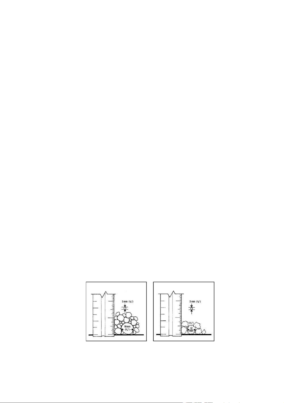
5.6 Gravel specification
Primary backfill specification:
•
Primary backfill material should be free-flowing granular material.
Compaction should be by lightweight rollers or vibratory plate. Compact gravel evenly
•
to ensure proper support for the tank. Make sure the vibrating machine does not come
in contact with the shell of the tank.
Tanks installations require primary backfill only within the region immediately
•
surrounding the tanks. This backfill must extend a minimum of 250mm outward from the
tank, and directly beneath the tank.
• Backfill material shall not be frozen or contain lumps of frozen material at any time during
installation.
• Use of other than specified backfill and bedding materials will void the tank warranty.
The following materials are approved as primary backfill:
Rounded pea gravel:
•
Minimum particle size 3mm, maximum 18 mm, compacted to a relative density of
>70%.
Gravel shall be clean and free flowing, free from large rocks, dirt, sand, roots, organic
•
materials or debris.
Upon screening analysis, the backfill material shall have no more than 5% by weight
•
passing 2.36 mm sieve.
Or
Crushed or processed stone:
Minimum particle size 3 mm, maximum 12 mm, compacted to a relative density of
•
>40%.
• Dry gravel density must be at least 1500 kg/m3. The material should be washed or screened
to remove fine particles.
• Upon screening analysis, the backfill material shall have no more than 5% by weight
passing a 2.36 mm sieve.
Pea Gravel Crushed Stone
16
Page 17
5.7 Concrete specification
Important:
Important
Vitae system, read the following sections carefully.
Semi dry concrete 25n grade with a ratio of 4.5 aggregate to 1 cement.
• Do not use standard concrete mixes where sulphates or similarly aggressive chemicals
are present in the groundwater.
• Lift height (rate of rise): Determine the lift height (m), or rate of rise (m/h) for the
specific, concrete type used, to ensure that a design pressure (P max) of 15kN/m2 on the
tank does not get exceeded.
• Vibration: The tank design assumes minimal compaction of the surrounding concrete.
Where necessary, this may be extended to include internal light vibration. Never use
deep revibration which will substantially increase the pressure on the tank, possibly
causing failure.
• Impact of concrete on discharge: Under no circumstances should concrete be discharged
directly onto the tank.
5.8 Topsoil requirements
Clean native topsoil shall not contain rocks larger than 36mm on largest dimension.
5.9 Electrical requirements
• Please ensure the electrical installation complies with all national regulations and
requirements
• Electrical installations must be carried out by a qualified
• Please note different electrical requirements are dependant on the size of the Tricel
T
he customers’ minimum responsibility shall consist of:
•
A single run of 1.5mm² three core (two conductors plus earth conductor) steel wire
armoured (SWA) cable from the customer’s distribution cabinet to the tank unit socket
box.
Cable protection via 10-amp MCB protected by (RCD), rated 230V, 30mA.
•
Bond the cable armour properly to the main earth at the premises.
•
Never disconnect the power to the air pump. It is imperative that it be running 24 hours a
•
day, every day.
.
and certified electrician.
17
Page 18
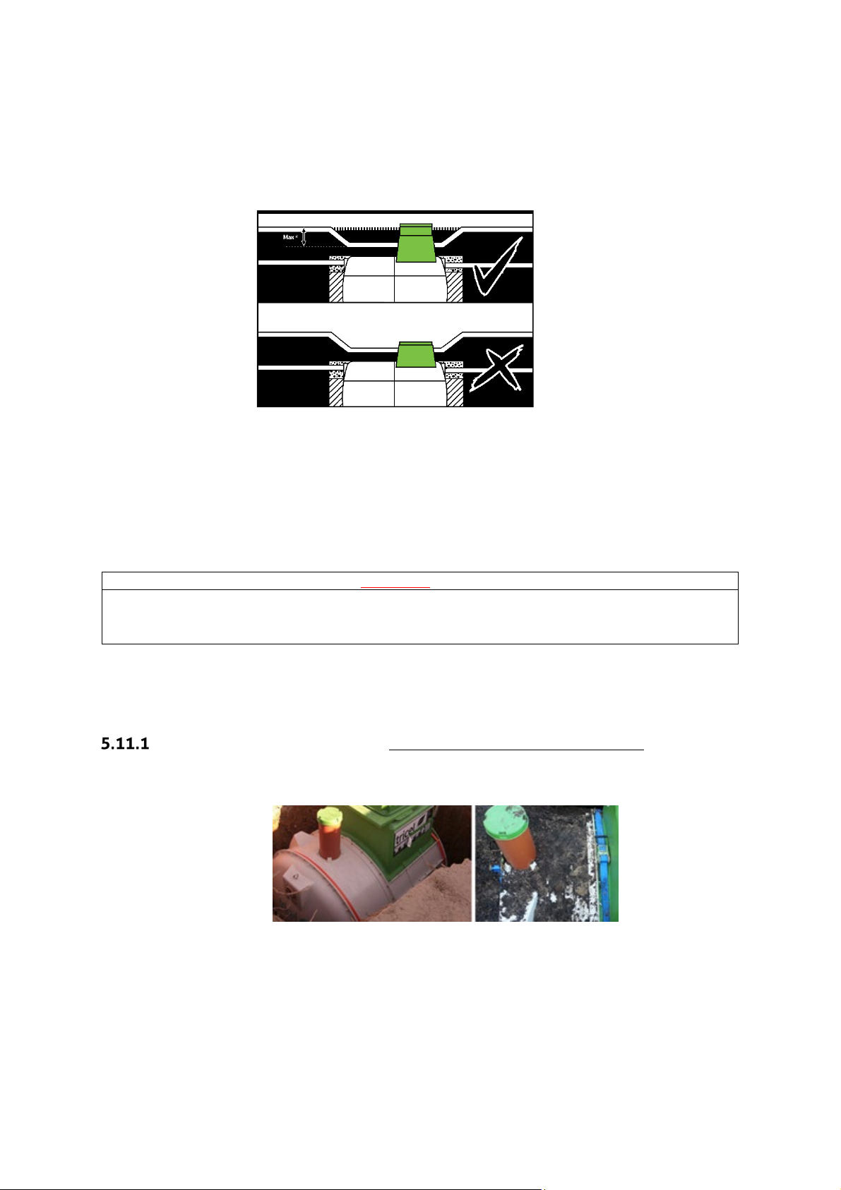
5.10 Risers
Important:
• Never place the manhole covers below ground level.
Do not allow ground water to enter the plant.
In the event that a Tricel Vitae requires a deeper than standard installation to align with the
wastewater outlet from the premises, manhole risers are available. These are to avoid the
access cover being positioning in a depression, as shown in the following diagram:
250mm, 500mm, and 750mm risers are available for the Tricel Vitae if required
•
(requires installation suitable for the site conditions, please refer to section 5.4,
‘Types of installation’).
The Tricel Vitae is suitable for a manhole riser which gives a maximum inlet invert of
•
1260mm
depth installation is necessary.
. However, the Tricel Vitae is not suited to areas where a more in-
• Only use
•
Tricel manhole covers and risers.
5.11 Non-standard
Alternative to concrete backfill (for wet sites without risers only):
• The option of securing the Tricel Vitae to a reinforced concrete slab or Deadman anchor by
way of straps may also be applied, as shown below:
• Tricel accepts no responsibility for the design of the concrete slab/Deadman
anchor. This solution should be designed by an on-site structural engineer to suit site
conditions.
• If implemented, position the straps as close to the bolted joints as possible.
18
Page 19
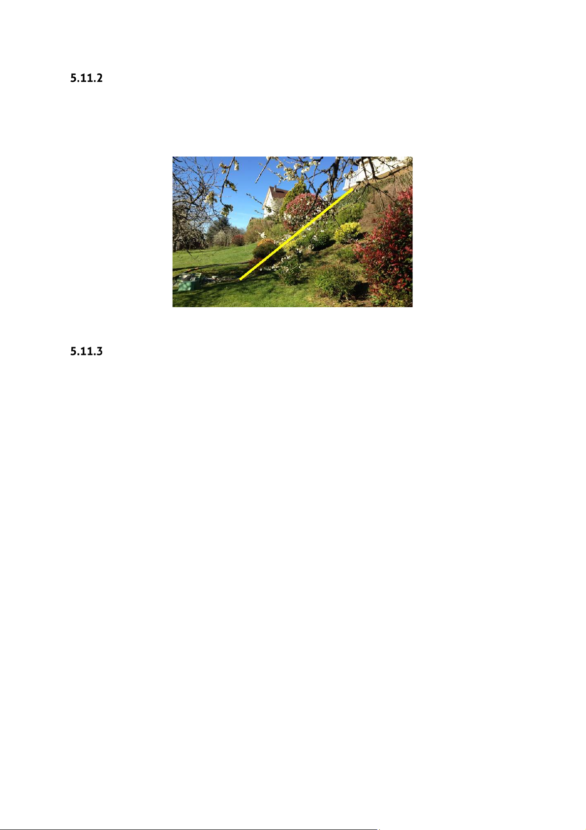
Sloping ground:
When the slope of the ground is 5% or more, it is recommended to install a retaining wall to protect
the tank from the lateral thrust. Concrete backfill may also in some cases be sufficient to protect
the tank. A qualified structural engineer must determine if a retaining wall is required in the
presence of a steep slope as shown in the picture below:
Proximity to rolling & static loads:
Minimum separation distances from:
• Rolling loads (e.g., vehicle traffic): 4 metres
• Static loads (e.g., dwelling house, shed): 3 metres
If the tank installation is in an area where traffic or other superimposed loadings can be
applied, consult a structural engineer for the design of a reinforced concrete slab to prevent
any load getting transferred to the tank (or its concrete surround). If this slab is constructed
immediately above the tank, separate it from the surrounding concrete by a compressible
material.
19
Page 20
5.12 Additional accessories
Warning
If high levels of grease/oil are present within the Tricel Vitae, the plant will not
components.
Grease trap
• Best practice indicates that a grease trap gets fitted before the
applications where high quantities of grease/oil exist in the wastewater.
•
For the grease trap tp continue to perform effectively, it must be
monitored/maintained on a regular basis and emptied when required.
achieve the required treatment quality and it will reduce the lifespan of plant
Tricel Vitae, particularly in
Sampling chamber
•
Best practice indicates that a sampling chamber is fitted after every
easy access for sampling purposes.
• Care should be taken to ensure that the sampling apparatus does not come into contact with
the pipework or walls of the sampling chamber to avoid contamination of the sample.
Ensure that the outlet is installed high enough in the sampling chamber to allow for the
•
required sampling volume to be retained in the bottom of the sampling chamber.
• The inlet/outlet pipework installed in the sampling chamber must be minimum diameter of
110mm.
Tricel Vitae
to allow
20
Page 21

6 Capsule installation
Installation of the capsule should only take place after the tank is installed within the ground.
Connect the air hoses to the corresponding coloured hoses on the capsule by means of the
black clips supplied. The capsule should then be mounted onto the shaft on the clearwater
lifter (blue) in the aeration chamber.
Following this, rotate so that the hoses wind around the capsule. Do not cut the hosing as they
need to be long enough to allow the removal of the capsule from the tank during times of
inspection. Winding the hoses around the capsule helps manage the excess length.
Plug the vent hose (red and blue striped) into the connection located on the bottom of the
access cover. The cable coming from the control panel should now be plugged into the plug
socket provided, which should be wired up to the house using the wiring diagram, also
provided.
7 Commissioning
Once site installation, plumbing and the electrical installation reach completion, the Tricel
Vitae is now operational. The plant should already be half filled with water during the
installation phase. If not, it should be half filled before its first use.
The start-up instructions for the control panel are below. All plants come fitted with an alarm
which will alert to irregularities in the system. This alarm will continue sounding as long as
the problem is occurring, or until manually muted.
The plant runs 24 hours a day, seven days a week, all year round for optimum purification. In
periods of low occupancy, the sludge return re-circulates the liquid in the system ensuring
continuous performance. In periods of overload the sludge return system passes the effluent
back into the primary chamber, so it passes through the aeration chamber again which ensures
continuous performance. It may take up to 13 weeks for the biomass to become fully
established and to reach optimum purification.
As stated previously, all plants come fitted with an alarm which will alert to any irregularities
in the system.
21
Page 22
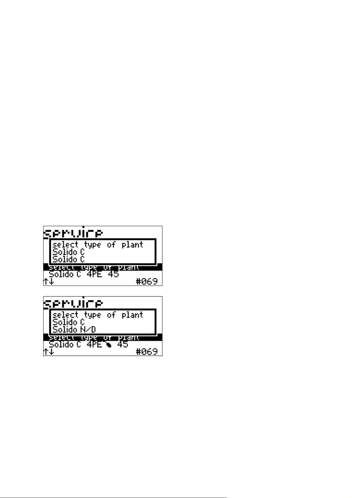
7.1 Control panel start-up
Plug the cable into the control panel.
Switch on the control panel.
Once on, a few settings should get verified. The control panel will “beep” until the input of
the password.
Below is a guide to help with the settings:
Set important plant parameters during start-up. All of the three-line pop-up menus have the
same structure:
First line: Title (which parameter is being set?)
Second line: Current setting
Third line: New setting if required (select using arrow buttons)
Example:
The following parameters are requested in the following order, using the same logic:
22
Page 23
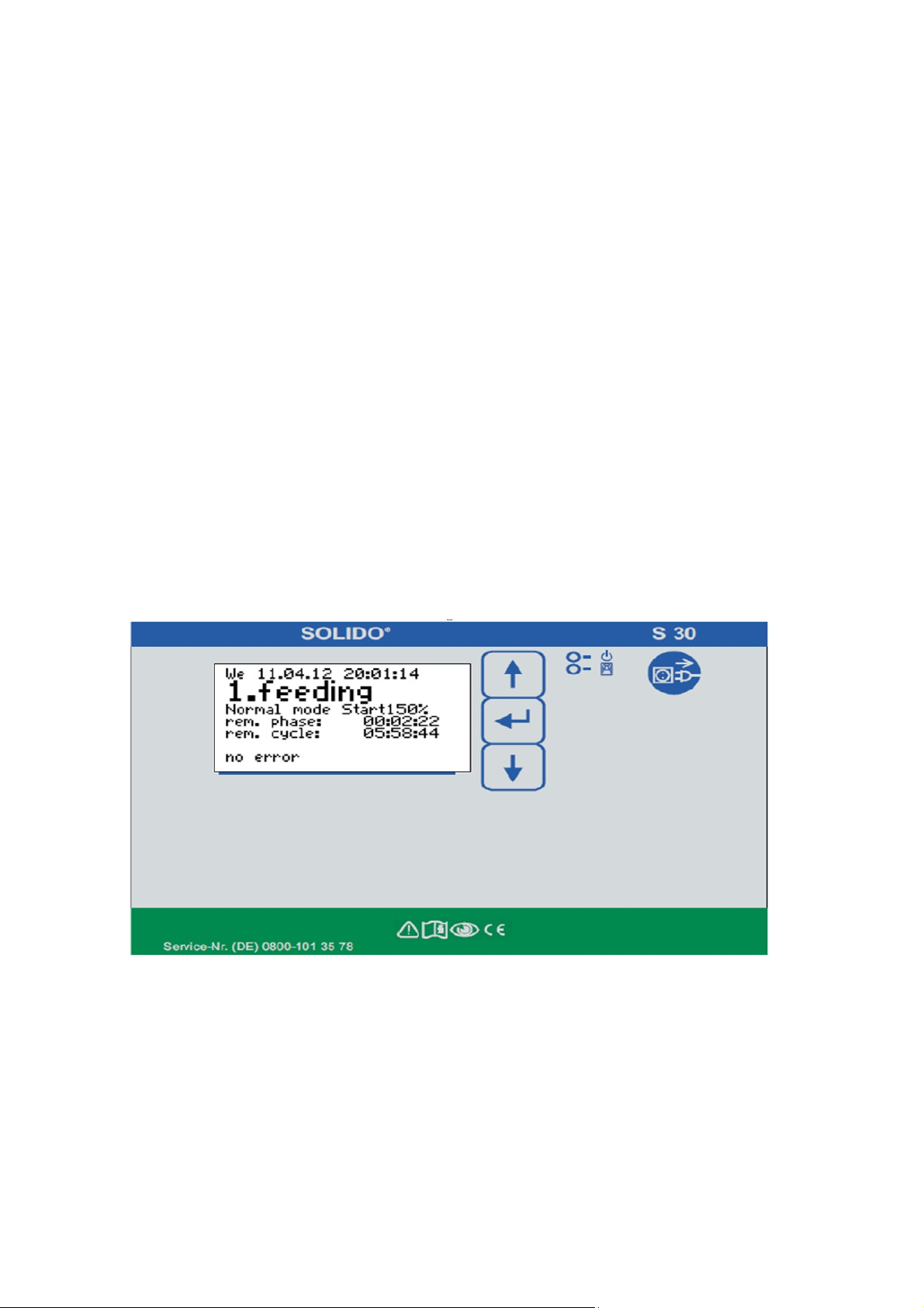
SOLIDO:
Language:
Set time and date: Set the current time and date
Select English
Password: Commissioning password is 7682
Type of plant: Select SOLIDO N/D
Number of Persons: Input the number of normal residents in your property (between
2 and 6)
Compressor: 80 l/min
Winter-eco: No
Test mode: The control unit switches on each of the lifters in turn; press any
button to end the test run.
Settings ok: Yes/No? (Yes: operation starts, No: back to the factory default state)
Test mode: The basic screen then appears, and the control unit starts the first
cycle.
Green LED, top: Indicates operational readiness (connected to the mains)
Red LED, bottom: Flashes to indicate an alarm message
Note: After commissioning start-up phase “start 150%” will be automatically activated, then
during 120 days the aeration time is increased to 150% of set value.
23
Page 24
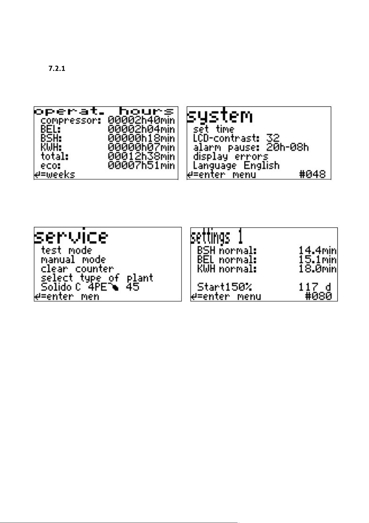
7.2 Operation of the control panel
Alarm pause: Night’s rest of the acoustical alarm,
hangeable
Start150%: start-up phase, aeration time at 150% of
Basic screen display
The basic screen is one of a number of layers of the same level which form the menu; you can navigate between the layers using the arrow buttons.
value, duration adjustable
24
Page 25
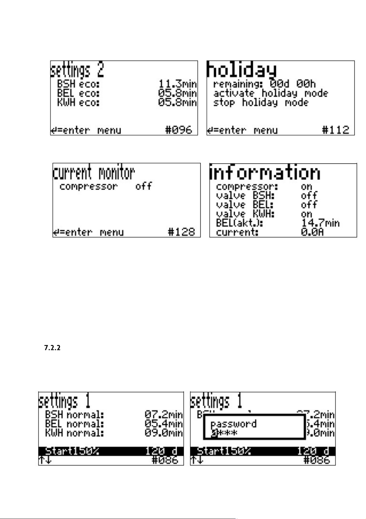
Holiday:
, plant then only runs in
conomy mode
BEL(
up phase
Max. 30 days can be set
akt.): Activated aeration time (resp. start-
-eco)
Press the middle button to move down a level to the sub-items in a menu. You can read the status
on the sub-items which get highlighted in black. The arrow buttons now allow you to select the subitems of the menu. If none of the sub-items are highlighted in black, you have returned to the screen
level above; here, the arrow buttons allow you to navigate between the main menu items. The
numbers at the bottom right (e.g. # 144) indicate the menu field (for internal use).
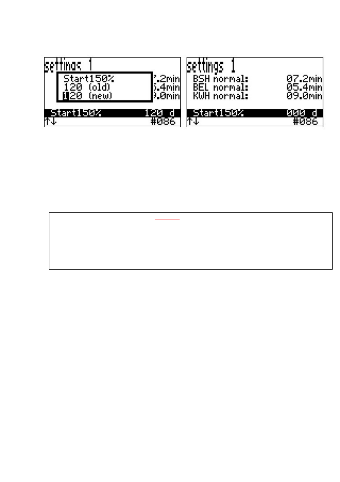
Start-up phase ‘Start 150%.’
After commissioning the controller, or changing the plant type, the start-up phase “Start150%”
will always be automatically activated. During the next 120 days, the aeration time increases to
150% of settled value. The duration is adjustable. To deactivate the start-up phase just set 0 days,
as follows:
25
Page 26
Warning
Any maintenance performed inside the tank represents a confined space. Therefore, the maintenance
precautions.’
8 Disposal of treated water
The treated wastewater from the Tricel Vitae should get disposed of as per guidelines from the
planning regulations issued by your local authority.
9 Maintenance
person must be suitably trained to work in confined spaces. Sewage and sewage effluent can carry
micro-organisms and gases harmful to human health. Only appropriately trained personnel can carry
out maintenance on the tank. Wear suitable protective equipment including gloves, goggles, etc., at
all times. Always remove contaminated clothing and protective equipment after completion of work.
Wash hands and face prior to eating, drinking or smoking. Please refer to section 1, ‘Health & Safety
• A certain amount of plant maintenance is required on an on-going basis to ensure that
the plant is working correctly.
• Ensuring this maintenance is the responsibility of the homeowner.
9.1 Regular maintenance
•
The vents around the base of the blower housing guarantee a fresh supply of air to the
air blower. All vents should be checked to make sure they are not blocked or obscured.
Ensure that the plant is running correctly by removing the blower housing and
•
inspecting the display on the control unit.
Inspect the pipework for blockages if necessary. The inlet and outlet should be
•
inspected and rodded to remove any obstructions if necessary.
9.2 Annual maintenance
• The
Tricel Vitae
guarantee the efficiency of the plant gets maintained. Accommodating service
personnel with clear access to the tanks is essential.
will require a full service (available from your supplier) once a year to
26
Page 27

9.3 Annual service (available from your supplier)
All plant functions
The functionality of blower(s)
Blower pressures
Replacement of blower filters
Diffusers monitored to check for dispersion of
air.
Inspection of Tricel covers and locks
Vents are clear of any blockages.
Clearing air-lifts of any blockages
Measurement of the quantity and condition of
bacteria in the aeration chamber
Measurement of sludge level in the primary
chambers
Calibration measurement
Important
•
all necessary safety precautions when
During routine servicing, the following items get checked, if applicable:
9.4 Production of sludge
The desludging of the
•
There is the potential danger of falling into the tanks during desludging when
manholes may be open – take
desludging.
•
Do not allow machinery/traffic drive over the Tricel Vitae. Maintain a distance of
at least 4 metres away from the manhole covers on the Tricel Vitae.
•
The manhole covers should never be left off an unattended
When the sludge is occupying 50% of the volume of the primary chamber desludging is
required. This activity is necessary when the sludge is 700mm deep. View the desludging
periods in the table in section 3.1 ‘Dimensions,’ these periods depend on the occupancy of the
dwelling. The
a vacuum tanker (Tricel recommend the use of a licensed company).
Tricel Vitae
has a separate desludging access point. Desludging is carried out with
Tricel Vitae
is the responsibility of the homeowner.
Tricel Vitae.
9.5 Desludging (emptying the solid waste from the primary chamber)
• Qualified personnel must perform the desludging.
• Please remove all floating and settled sludge from the primary chamber. All compartments
within the primary chamber must be desludged (please refer to section 3.2 ‘Tank Drawing’).
The primary chamber is identifiable by the fact that there is no aeration done in this
chamber. Therefore, there will be no air bubbles in these chambers during the aeration
function.
• Once the primary chamber has been desludged, fill it with fresh water. When loading the
primary chamber with fresh water, place the hose into the primary compartment and
position it closest to the aeration chamber. By doing this, it will reduce the risk of floating
solids blocking the airlifts.
27
Page 28
10 Operating conditions
Warning
Tricel shall not be liable for any damage or loss, including consequential loss, caused
prohibited material, in the plant.
by the failure of any plumbing equipment or failure caused by the inclusion of
The manufacturer’s installation, operation and maintenance instructions outlined in this
manual must be followed at all times to ensure the plant operates as designed. Any
variations to these conditions
and the discharge may not meet the required standards.
• The property owner has a legal responsibility to ensure that the plant does not
cause pollution, a health hazard or nuisance.
•
Desludging is a critical part of the successful operation of the
responsibility of the customer. Only competent and approved personnel should carry
out desludging. Desludging must get carried out when required as specified, and the
plant should be regularly inspected to check the depth of sludge in the primary
chamber. If desludging is deemed necessary, carry it out as soon as possible.
The electrical connection to the plant requires maintaining for it to function correctly.
•
This connection ensures that the
the airlifts will operate.
The
•
•
•
•
Tricel Vitae
includes many components (plumbing, ventilation, plant and polishing filter (if
applicable). Each element has to function correctly for the overall system to work
which is the responsibility of the customer.
If the installation of the plant is not correctly carried out, flooding, overloading,
electrical shock or floatation may occur. Tricel
installed plants.
Soakaways drains and the emptying of the primary chamber remains the responsibility
customer
of the
up of soakaways or drains, is not covered by Tricel.
To ensure the continuance of the
certain precautions:
o Do not exceed the design loading of the plant.
is one part of an overall wastewater treatment system which
. Damage to the plant, due to the influx of surface water or the backing
could result in the unit not performing to its full potential,
Tricel Vitae
plant has a continuous air supply and where necessary
is not responsible for incorrectly
Tricel Vitae’s
performance, the
customer
and is the
must take
o High volume discharges, such as those from swimming pools and Jacuzzi’s
must never enter the plant.
o Surface water must not enter the plant.
o Do not allow large quantities of chemicals to enter the plant including but not
limited to:
Detergent
Water softener
Disinfectants
Strong acids and alkalis, or photographic chemicals
Oil or grease
Petrol or diesel
28
Page 29

Pesticides
o Do not allow any of the following to enter the Tricel Vitae:
Large quantities of milk, alcohol or food
Large amounts of bleaches or cleaners
Baby wipes, cosmetic and cleaning wipes
Sanitary towels
Tampons
Kitchen paper
Nappies
Medication
•
Service personnel must be provided with clear access to the plant.
If others size the plant, Tricel will supply to these specifications. In this case, the
•
responsibility lies with others in relation to the maximum flow/litres per day, the plant
capacity and retention times. Similarly, if Tricel size the plant and a greater load is
placed on the plant, for example, but not limited to the addition
of extra houses,
bedrooms, schools, crèche’s etc. or by other means Tricel is not responsible for the plant
regarding overloading or quality of effluent as the retention times may be compromised.
• Safety precautions must never be removed or by-passed during normal operation of the
plant.
• When working with chemicals, avoid direct contact with chemicals as far as possible. Before
use, always read the instructions and take the relevant precautions where necessary
regarding the chemical.
• All safety instructions and danger warning signs located on the plant must always be kept
in a readable condition.
• Persons under the influence of alcohol must not operate the plant.
• The power supply to the plant must be turned off during maintenance and cleaning work at
the plant.
• It is not permitted to use the system for another purpose other than described by the
manufacturer.
• The tank is not suitable for vehicular traffic. Tricel also recommends fencing off the area to
prevent livestock herds
Tricel are not responsible for the following, and such occurrences will void the
•
warranty:
Unusual use – used for purposes not intended by the manufacturer
o
Flooding
o
Lightning strikes/power surges
o
from accessing the plant.
o Tricel does not commission the plant
29
Page 30
11 Troubleshooting
Thermal overload protection
temperature
Low line voltage or wired
incorrectly
An electrician should check the power supply to
the plant
Diaphragm damaged/torn (If
applicable)
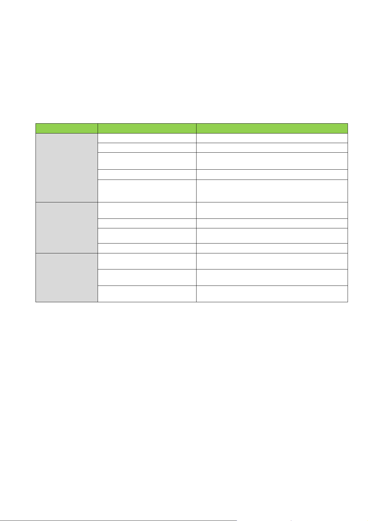
Properly installed, operated and maintained plants will give many years of trouble-free
service. All plants come fitted with an alarm, which will alert to irregularities in the plant. If
a fault occurs, a buzzer will sound to indicate that there is a problem with the plant. If
required, you can mute the buzzer by holding the middle touch key on the control unit for 5
seconds, until the problem gets fixed. Once fixed, the alarm will reset automatically. All
electrical work shall be carried out by a qualified person.
Symptom
The blower will
not start or run
Blower operates
but delivers no air
Plant fills above
the working
water level
Possible Causes
Fuse blew (if applicable)
Low line voltage and wet
triggered by high ambient
Defective blower malfunction
Subsurface disposal plant
Stormwater flooding
Discharge hose/pipe blocked
Tripped breaker Reset breaker
An electrician should check the power supply to
electrics
Defective blower A qualified person must check the blower
Filter blocked
clogged
Replace with a fuse of suitable size
Allow the blower time to cool. The blower will
automatically restart when cooled sufficiently
Replace damaged diaphragm
A qualified person must check the air blower
Contact installer to repair subsurface disposal
plant/ percolation area
Redirect stormwater drains. Stormwater must
Find blockage and remove or replace the
Solution
the plant
Replace filter
never enter the plant
damaged hose/pipe
30
Page 31
11.1 Odours
Symptom
Possible Causes
Solutions
Pipe connections to toilets/drain not
Check that the traps/U - bends in the drains are
Air vents on pipework not installed
Ensure all effluent pipes are vented
eve of the roof.
Pipework is damaged, blocked or not
Inspect pipework to ensure it is undamaged
Pipework to or from the tank is
Check the level of wastewater in the tank.
installed correctly to the tank.
Chemical kill of bacteria
Empty the tanks and fill with fresh water
No oxygen is entering the tank
Clear any blockages in the vents
The control unit has detected a fault
Resolve the issue and restart the plant
No power supply to the control unit
Connect the power supply/ replace the fuse
Too much grease is entering the plant
Install/empty grease trap
Smoke bombs/pellets, available from a plumber’s merchants, can be used to trace
the source the odour.
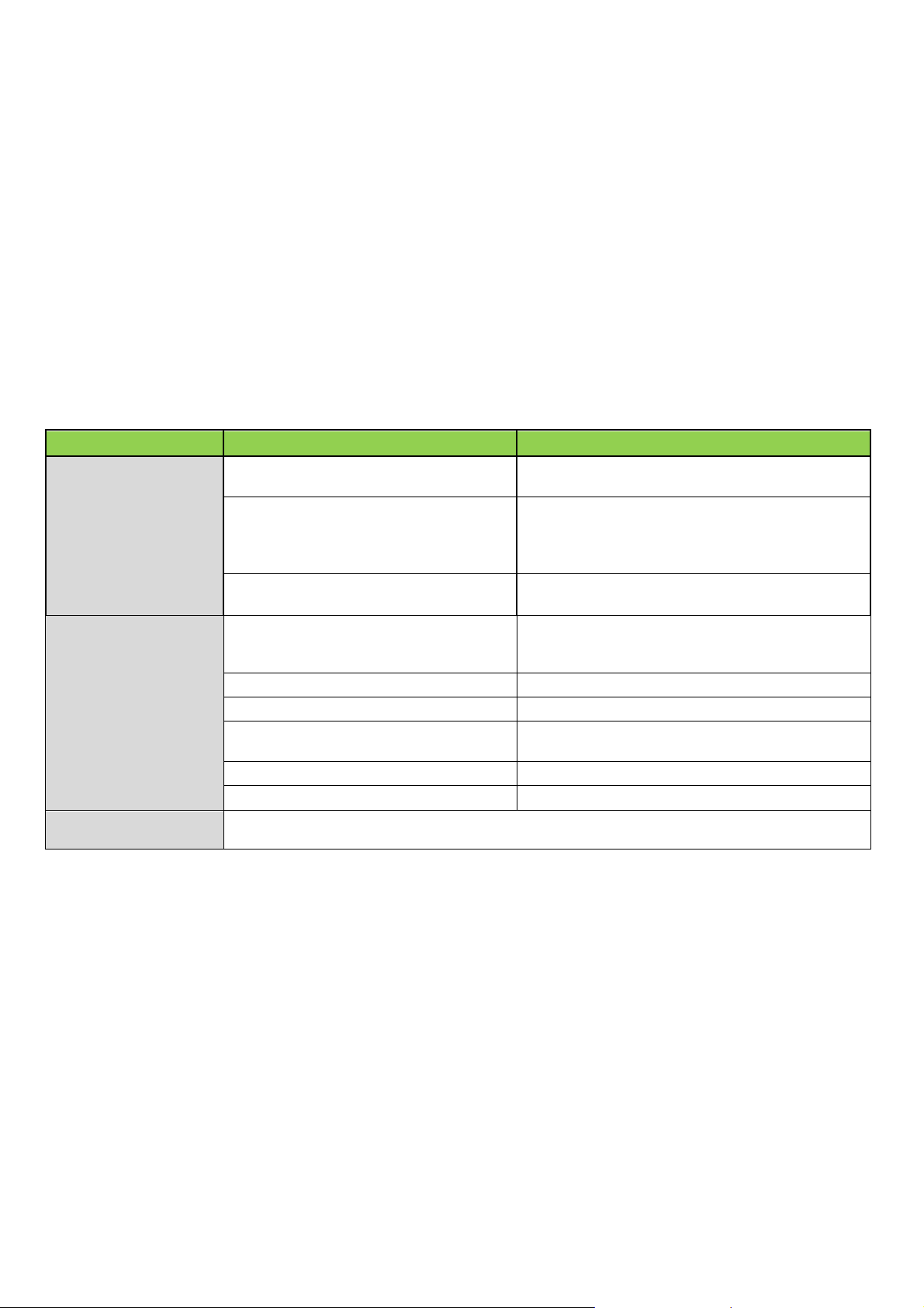
When the Tricel Vitae gets installed and operated correctly, there should be no strong odour in the
area adjacent to the plant. The presence of a strong odour would indicate that the plant is not
working effectively.
Note:
Before taking any corrective action, always positively identify the real source of the odour.
Check if the odour is coming from another outside source such as a storm drain. All Tricel
Vitae’s plants vent gases back through soil pipe’s and out roof vents. Improperly installed roof
vents can cause odour problems. Traps in drains prevent odours from entering the home. To
function, they must contain water and be sealed correctly.
Strong effluent odour
directly outside the
house or inside the
house
Strong effluent odour
directly over the tank
Note:
connected correctly
correctly
installed correctly
suffering blockage
and stopped running
correctly. Vents are typically fitted to all
pipes, and they should be higher than the
Ensure the pipes are not blocked and are
fitted and the joints sealed
and clear of obstructions or sagging
31
Page 32

12 Certification
Material
Glass-Reinforced Plastic (GRP)
Technology
Sequential Batch Reactor
Shape
Horizontal cylinder with domed ends. 620mm x 620mm and
Ø200mm Access openings as required.
12.1 Declaration of performance
- Declaration of Performance
DOP02SBRUK06201403
1. Classification of Product:
A small wastewater treatment system for up to 50PT – Packaged and/or Site Assembled Domestic
Wastewater Treatment Plant as set out in EN12566 Part3
2. Name of Product:
Tricel Vitae 6
3. Product Characteristics
4. Intended for Use:
5. Name, Address and Contact Information of Manufacturer:
Tricel (Killarney)
Ballyspillane Ind Est
Killarney
Co. Kerry Ireland
Tel: ++353 (0) 64 6632421
Web: www.ie.tricel.eu
6. Plant of Assessment of Verification as set out by the CPR, Annex V:
To treat light commercial wastewater for up to 6 population equivalents.
Plant 2+
7. Name, Address and Notified Body Number of Notified Body who carried out Initial Type
Testing
8. Declared Performance: Treatment Performance
Prüfinstitut für Abwassertechnik GmbH
Hergenrather Weg 30
D-52074 Aachen
Germany
NB 1739
32
Page 33
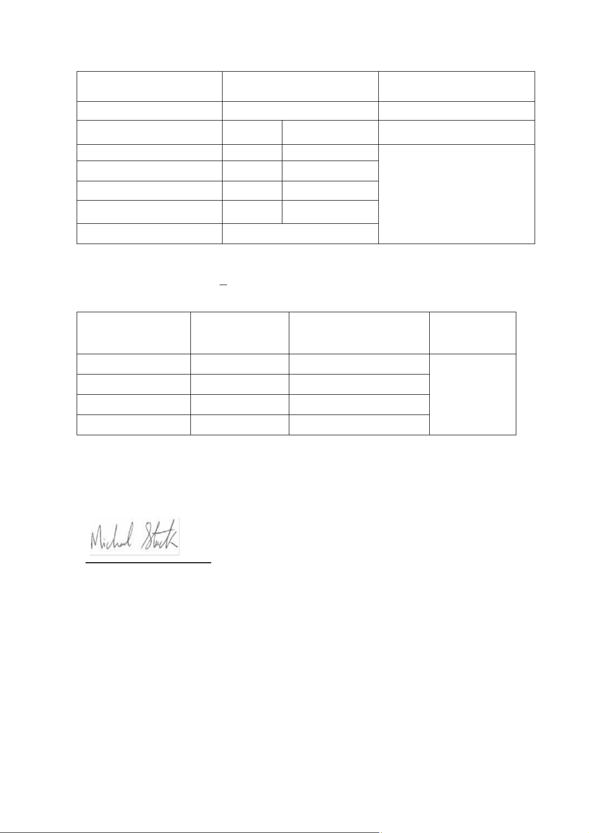
Essential Characteristic
Performance*
Harmonized Technical
Specification
Nominal Organic Daily Load
0.30 kg/d
COD
94.3% 37.3 mg/l
Electrical Power Consumption
0.65 kWh/d
Essential Characteristic
Method
Performance
Harmonized
Water Tightness
Vacuum Test
Pass
Crushing Resistance
Pit Test
Pass (also wet conditions)
Durability
Pass
Reaction to Fire
Class E
Nominal Hydraulic Daily Load
BOD
5
0.75 m3/d
98.1%
6.1mg/l
SS
NH4**
*Performance results obtained at an average organic daily load of 0.25kg/d and a daily hydraulic
load of 0.9m
3
/d
**Determined at temperatures >12oC
Material Performance
96.2%
94.2%
13.8 mg/l
2.9mg/l
EN12566-3
Technical
Specification
EN12566-3
9. The performance of the product identified in point 2 conforms with the declared
performance in Point 8.
This declaration of performance is issued under the sole responsibility of the manufacturer identified in point 4.
Michael Stack Managing Director
3/06/2014
33
Page 34
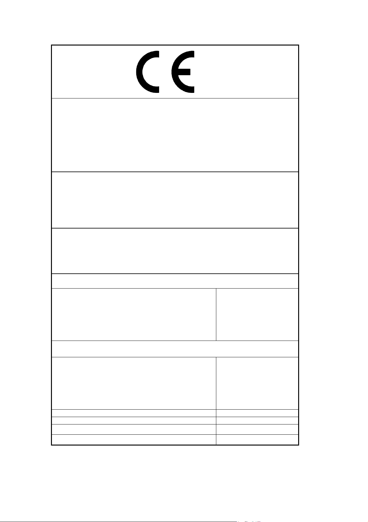
Tricel (Killarney)
DOP02SBRUK06201403
-
Material: GRP
Treatment capacity
As Set Out in
The effectiveness of treatment:
COD: 94.3 %
NH4-N: 94.2 %
Water tightness: (Vacuum test)
Pass
Crushing resistance: (Pit test)
Pass (also Wet
conditions)
Durability
Pass
Fire Resistance
Class E
Ballyspillane Ind Est
Killarney
Co. Kerry
Ireland
13
-
Product: Tricel Vitae 6
Notified Body:
Number.:
-
Nominal organic daily load: (BOD5)
-
Nominal Hydraulic daily flow (QN)
EN 12566-3
Packaged wastewater treatment plants
for treatment of domestic wastewater
52074 Aachen
Prüfinstitut für Abwassertechnik GmbH
Hergenrather Weg 30
NB 1739
Table CE
for each Model
Treatment efficiency ratios (at tested organic daily load
BOD5 of 0,25 kg/d and daily hydraulic flow of 0.75m
3
/d)
BOD5: 98.1 %
SS: 96.2 %
34
Page 35

The Tricel Vitae wastewater treatment plants have successfully passed the stringent European
testing process and are approved to the new European standard EN 12566-3 Small wastewater
treatment plants for up to 12 PT-Part 3: Packaged and/or site assembled domestic wastewater
treatment plants. Tricel wastewater treatment plants were placed through a rigorous 38-week
test, by the certified laboratory PIA GmbH-Testing Institute for wastewater technology in
Aachen, Germany www.pia-gmbh.com.
The Tricel Vitae passed all structural testing (crush test & durability test) carried out by PIA
staff. Water tightness tests were performed by PIA at our headquarters on the range of tanks
up to P12 successfully passed all of the required tests.
35
Page 36

13 Terms & conditions
Subject to our standard terms and conditions, which are available on request.
In accordance with our standard policy of product development, this specification is subject to
change without notice. (July 2018)
36
Page 37

NOTES
This page is intentionally left blank.
37
Page 38

NOTES
This page is intentionally left blank.
38
Page 39

NOTES
This page is intentionally left blank.
39
Page 40
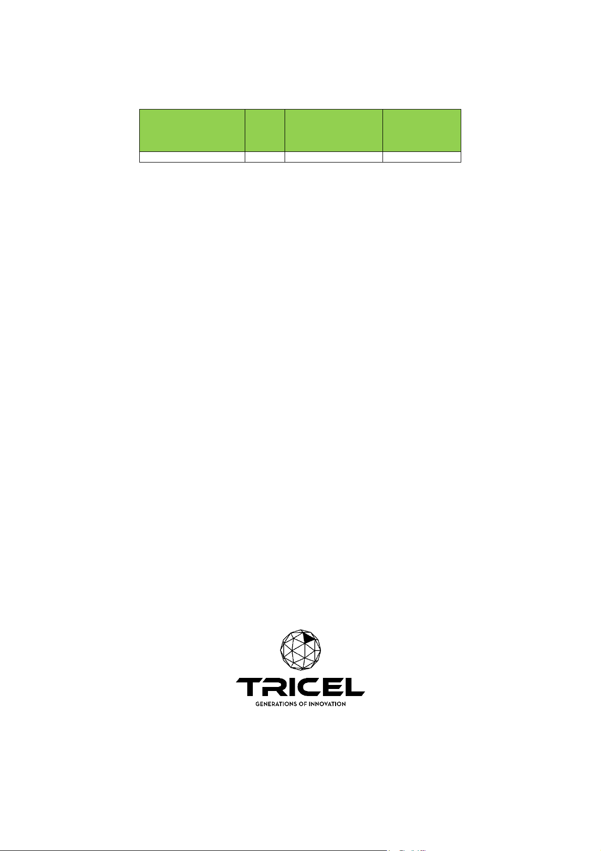
Tricel
This
Nominal Organic
Nominal
Tricel Vitae UK6
0.36
900
Identification
Code
Tricel
is a
Daily Load
(BOD5) (Kg/day)
Hydraulic
Daily Flow
(litres/day)
Tricel (Killarney) Unlimited Company Trading as Tricel
Ballyspillane Ind. Est. Killarney, Co. Kerry, Ireland
In accordance with Tricel normal policy of product development these specifications are subject to change without notice.
40
 Loading...