

Page 1
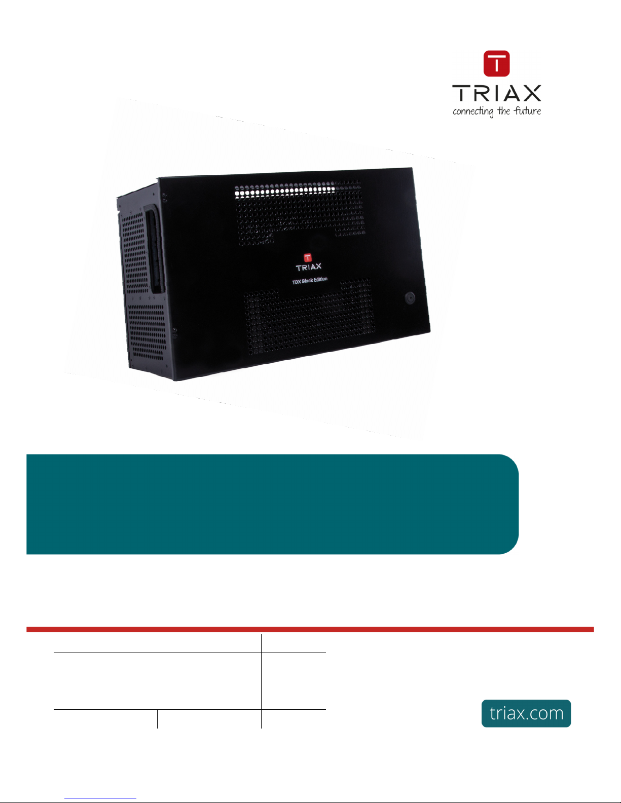
TDX Headend System Main Unit
Black Edition
User Manual
Content / Inhaltsverzeichnis / Table des matières
Model Item no.
TDX Headend System Main Unit – Black edition 492091
Version
891072C
Date
01/2017
EN
Page 2

TDX Headend System Main Unit
Black Edition
EN
2
Safety Precautions ....................................................................................................................................................................................................... 3
Environment .................................................................................................................................................................................................................. 3
Power supply ................................................................................................................................................................................................................ 3
Weight ........................................................................................................................................................................................................................... 3
Earth .............................................................................................................................................................................................................................. 3
Disposal ........................................................................................................................................................................................................................ 3
Black Edition – what’s new .....................................................................................................................................4
New features in Black edition ...................................................................................................................................................................................... 4
New user interface (GUI) – what has changed ............................................................................................................................................................ 4
Service Agreement ....................................................................................................................................................................................................... 4
Fixed PID, filter + remap ............................................................................................................................................................................................... 4
Introduction ............................................................................................................................................................5
Box contents ................................................................................................................................................................................................................. 5
Exterior .......................................................................................................................................................................................................................... 5
Interior ........................................................................................................................................................................................................................... 5
Single headend installation ....................................................................................................................................7
Mounting ....................................................................................................................................................................................................................... 7
Ventilation requirements .............................................................................................................................................................................................. 7
Power / Earth / ID switch .............................................................................................................................................................................................. 7
Multi Headend installation ......................................................................................................................................8
RF output ....................................................................................................................................................................................................................... 8
Power ............................................................................................................................................................................................................................ 8
Ventilation requirements .............................................................................................................................................................................................. 8
1. Horizontal ......................................................................................................................................................................................................... 8
2. Vertical ............................................................................................................................................................................................................. 8
Connection units – direct connection .......................................................................................................................................................................... 9
1. 1x Main – 1x sub .............................................................................................................................................................................................. 9
2. 1x Main – 2x sub .............................................................................................................................................................................................. 9
Connecting units – switch connection ...................................................................................................................................................................... 10
Multi headend installation – Fiber optic .................................................................................................................................................................... 10
Resetting IP adress..................................................................................................................................................................................................... 10
Input modules ............................................................................................................................................................................................................. 11
Input module types ..................................................................................................................................................................................................... 11
Inserting input modules.............................................................................................................................................................................................. 11
Attaching cables ......................................................................................................................................................................................................... 12
Looping cables............................................................................................................................................................................................................ 12
Removing input modules ............................................................................................................................................................................................ 12
Moving input modules ................................................................................................................................................................................................ 12
Output modules .......................................................................................................................................................................................................... 13
Output module types .................................................................................................................................................................................................. 13
Inserting output module ............................................................................................................................................................................................. 13
Removing output module ........................................................................................................................................................................................... 13
Auxiliary modules ....................................................................................................................................................................................................... 13
System monitoring ...............................................................................................................................................14
Input modules – LED status ....................................................................................................................................................................................... 14
Output modules – LED status .................................................................................................................................................................................... 14
Service tool - System requirements ......................................................................................................................15
Computer minimum requirements ............................................................................................................................................................................. 15
Static IP address ......................................................................................................................................................................................................... 15
Starting service tool.................................................................................................................................................................................................... 16
Overview...................................................................................................................................................................................................................... 16
Tabs............................................................................................................................................................................................................................. 17
Communication circle ................................................................................................................................................................................................ 17
System icons............................................................................................................................................................................................................... 17
Misc. buttons .............................................................................................................................................................................................................. 17
Configuration buttons................................................................................................................................................................................................. 17
Administration......................................................................................................................................................17
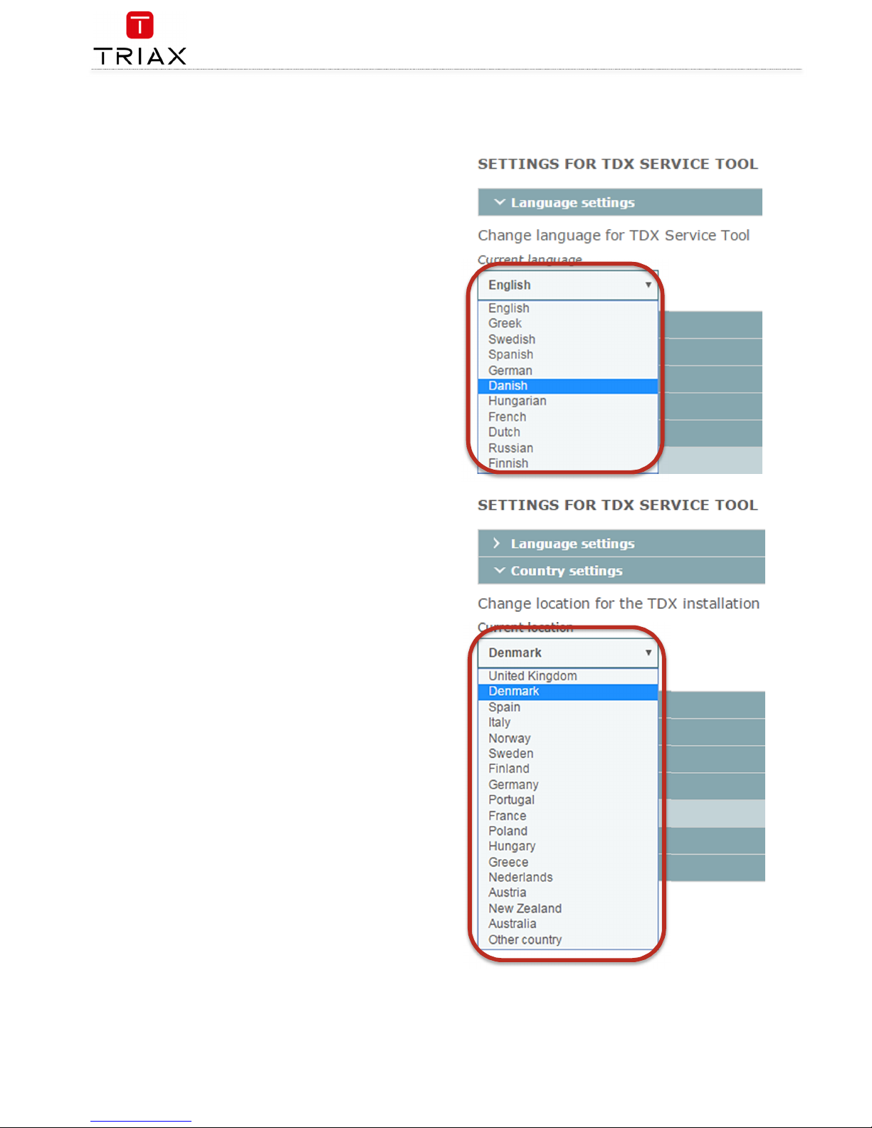
Language .................................................................................................................................................................................................................... 18
Location ...................................................................................................................................................................................................................... 18
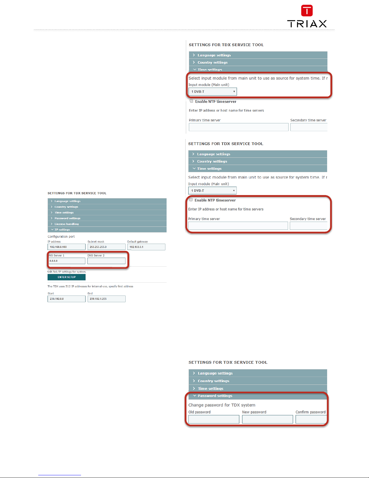
Time zone ................................................................................................................................................................................................................... 18
Time set by NTP server .............................................................................................................................................................................................. 19
Security ....................................................................................................................................................................................................................... 19
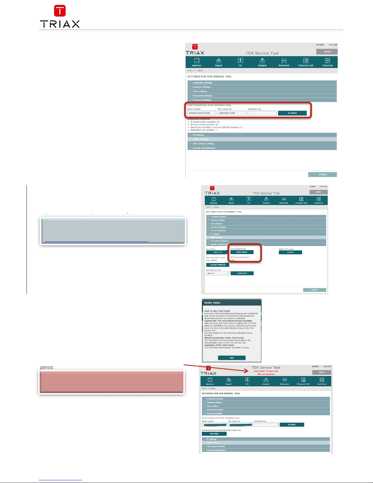
Features and License Keys ........................................................................................................................................................................................ 20
How-To get License Keys ........................................................................................................................................................................................... 20
IP settings ................................................................................................................................................................................................................... 21
SNMP settings ............................................................................................................................................................................................................ 22
CAS server settings .................................................................................................................................................................................................... 23
Rebooting .................................................................................................................................................................................................................... 23
View system log .......................................................................................................................................................................................................... 23
Firmware updating ...................................................................................................................................................................................................... 24
Firmware clean up ...................................................................................................................................................................................................... 24
Page 3

TDX Headend System Main Unit
Black Edition
3
EN
Format file system in flash ......................................................................................................................................................................................... 25
Force TDX systemcontroller in failsafe mode ........................................................................................................................................................... 25
Reinitialize SD card ..................................................................................................................................................................................................... 25
IP out service list ........................................................................................................................................................................................................ 26
System information ..............................................................................................................................................27
Viewing system information ...................................................................................................................................................................................... 27
Duplicated PID‘s.......................................................................................................................................................................................................... 27
Managing configuration files ................................................................................................................................28
Creating ....................................................................................................................................................................................................................... 28
Activating .................................................................................................................................................................................................................... 28
Deleting ....................................................................................................................................................................................................................... 28
Saving.......................................................................................................................................................................................................................... 28
Uploading .................................................................................................................................................................................................................... 29
IP Input configurations .........................................................................................................................................30
Creating ....................................................................................................................................................................................................................... 30
Specifying EIT/EPG source ........................................................................................................................................................................................ 31
Specifying Alternative EIT/EPG source ..................................................................................................................................................................... 31
EIT for Viasat services................................................................................................................................................................................................ 32
Modifying .................................................................................................................................................................................................................... 32
Deleting ....................................................................................................................................................................................................................... 32
IP output configurations .......................................................................................................................................32
Creating ....................................................................................................................................................................................................................... 33
Modifying .................................................................................................................................................................................................................... 34
Deleting ....................................................................................................................................................................................................................... 34
EIT/EPG output .....................................................................................................................................................34
EIT – every IP service ................................................................................................................................................................................................. 35
EIT – barker channel................................................................................................................................................................................................... 35
PID handling ................................................................................................................................................................................................................ 36
SNMP traps ..........................................................................................................................................................38
Safety Precautions
Environment
Operating temperature -10 C to +50 C.
Storage temperature -20 C to + 70 C.
Max. Operating humidity 80% (RH).
Max. Storage humidity 90% (RH).
Power supply
The input voltage must be 190-264 VAC. ~ 45/65 Hz / 280 W (Max).
Use only power connections installed by professionals.
Weight
Minimum weight 10.5 kg Maximum weight 13.8 kg*
Earth
Headend units must be correctly earthed according to applicable national regulations.
Disposal
This product may not be disposed of with general household waste.
Follow applicable national legislation when disposing of this product.
Attention !
EN
Failure to comply with the specified precautionary measures may cause serious injury to persons or damage to property. The installation
and commissioning may only be performed by suitably qualified persons, technicians or installers in compliance with safety regulations.
Damage due to improper installation and commissioning, defective connectors on cables or any other incorrect handling will void the
warranty.
CAUTION: The safety requirements are according to EN 60728-11 and must be observed.
Disconnect mains power before working on electrical systems.
Any additional electrical wiring requirements should always be installed by a suitably qualified person(s).
Installation or service work should NEVER be undertaken during electrical / thunderstorms.
Page 4

TDX Headend System Main Unit
Black Edition
EN
4
Black Edition – what’s new
New
f
eatures
in
Black edition
New features have been implemented in the Black edition:
From S/W edition 4.0.1 the user interface (GUI) has been updated – more clear, more understandable and more easy in use;
entirely based on HTML5
A Service level agreement (SLA) is introduced for dedicated service and customer/end user satisfaction.
The SLA comes in 3 levels.
New fixed PID feature that can be filtered and remapped.
Fan noise has been reduced by 3dB
New user interface
(GUI)
–
what has changed
In the new GUI there has been following changes
New updated GUI – more clear, more understandable and more easy in use; and its written in HTML 5
Port forwarding, for remote control – prior to this new S/W release, you had to use
- Port 80, 943, 4530, 4531
In the new GUI
only port 80
Is required – much more simple and secure to setup remote management.
Due to this, the remote management is useable both on PC, tablet and smartphone.
The new GUI have been tested on the following browsers:
- Mozilla firefox ver. 46.0.1 or newer
- Google Chrome ver. 50.0.2661 or newer
- MS internet explorer 11 ver. 11.0.9600.18314 or newer
The new GUI reports if the software is registered or not
The ADMIN button has slightly changed position
Navigation information has replaced the BACK button
Highlighted information and more clear warnings, etc.
New failsafe image – never lose your setup.
Service Agreement
TRIAX Service Agreement, the safe & sound deal, comes in 3 levels – Pay-As-You-Go, BASIC and PLUS.
The TRIAX Service Agreement ensures your solutions are always up and running, always up to date and always backed up by the best service
and support; helping you operate a professional and profitable business.
Your Service Agreement benefits:
Supported Setup, including free of charge 30 day installation period with unlimited access to features.
Supported installations and solutions.
Easy online access to the Trouble Ticket System, Product Registration Tool, new SW versions, release notes, new License Keys,
how-to guides and much more.
Fixed PID, filter + remap
The PID (Packet identifier) handling has been changed significantly
Fixed PID – the PID value is now fixed at the output after a reset of the TDX system
PID filter – the elementary streams can now be removed from output of the TDX system
PID remap – the PID value can now be changed at the output of the TDX system
Page 5
TDX Headend System Main Unit
Black Edition
5
EN
Introduction
The TDX cabinet is designed to accommodate up to 16 input modules and 6 quad output modules. Up to three TDX headends can be combined as one
system of up to 48 input muxes and 72 output channels.
The TDX headend system accommodates up to 490 services.
All incoming signals from input modules initially arrive in the TDX service-pool, where conversion to defined output signals occurs, after which the
converted signals are fed to output modules.
Box contents
TDX headend unit,
1 x TDX Key 775310
2 x Mounting brackets 775285
4 screws (M4 x 8 hexagon ISO 7380)
840200)
1 x Torx® key (2.5 mm) 848603
1 x Power cord
User guide.
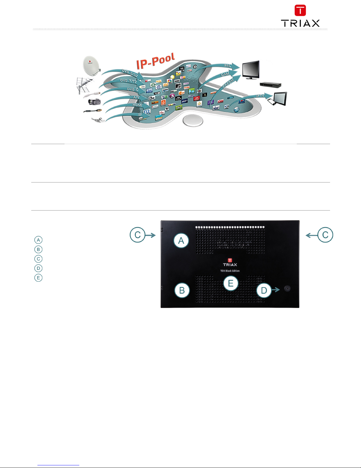
Exterior
Input module area
Output module area
Mounting brackets
Lock
Headend status LEDs
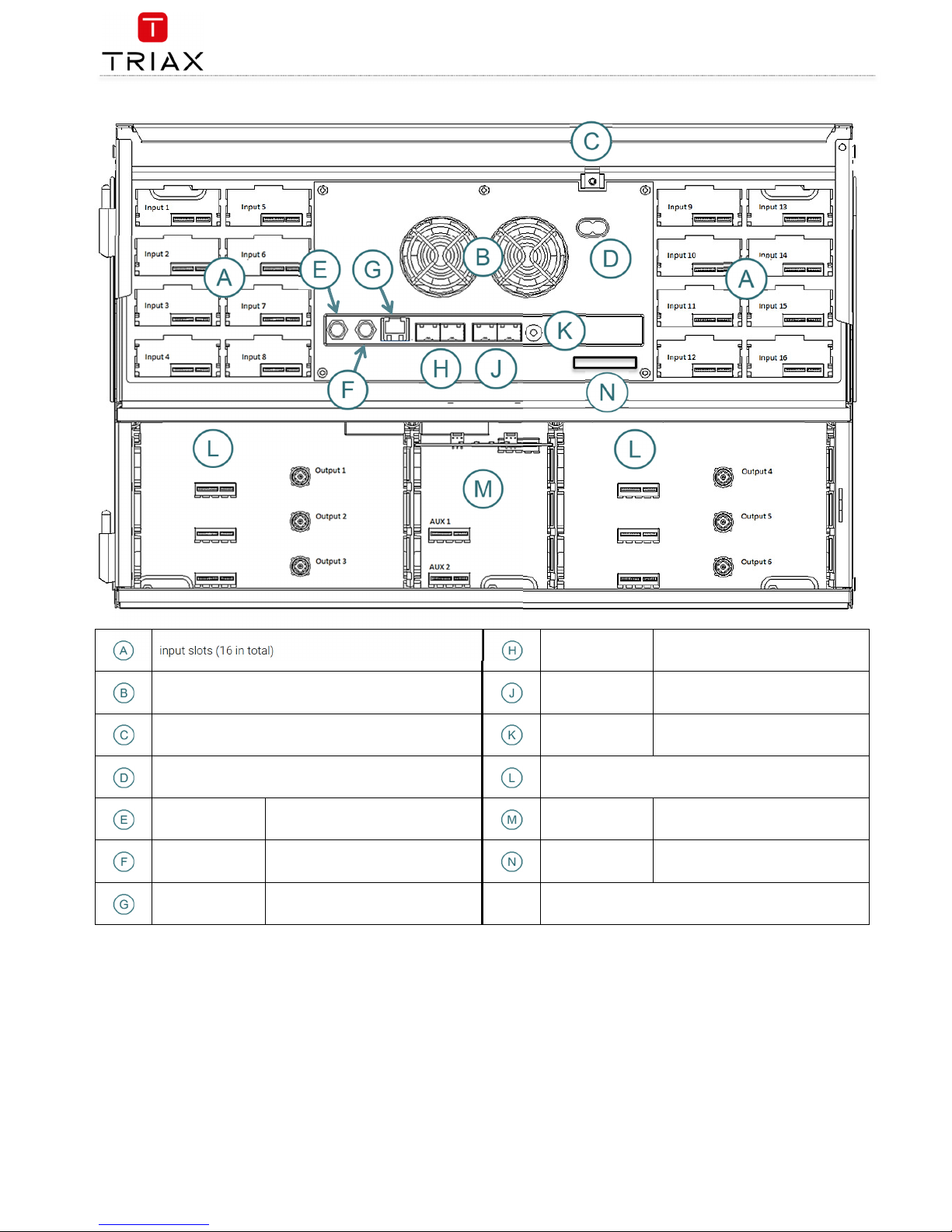
Interior
Page 6
TDX Headend System Main Unit
Black Edition
EN
6
input slots (16 in total)
AUX 1 & 2
Distributes services from IP output
modules
Extractor fans
Link 1 & 2
Connects the main unit with subunits 1
and 2. Can also be used in conjunction
with IP input and output
Earth terminal
ID switch
Switch for setting the ID of the main
unit and the two subunits
Output slots (6 in total )
RF output
Distributes the RF channels form the
output modules using an F-connector
Slot 1 & 2 for
auxiliary boards
Auxiliary boards are used in connection
with IP output modules
Test point -20dB RF test point of output (-20dB)
Secure Digital (SD
card)
Memory card for storage of the system
configuration (behind panel)
Configuration port
Ehternet configuration port for setting
up the headend unit
Page 7
TDX Headend System Main Unit
Black Edition
7
EN
Single headend installation
Mounting
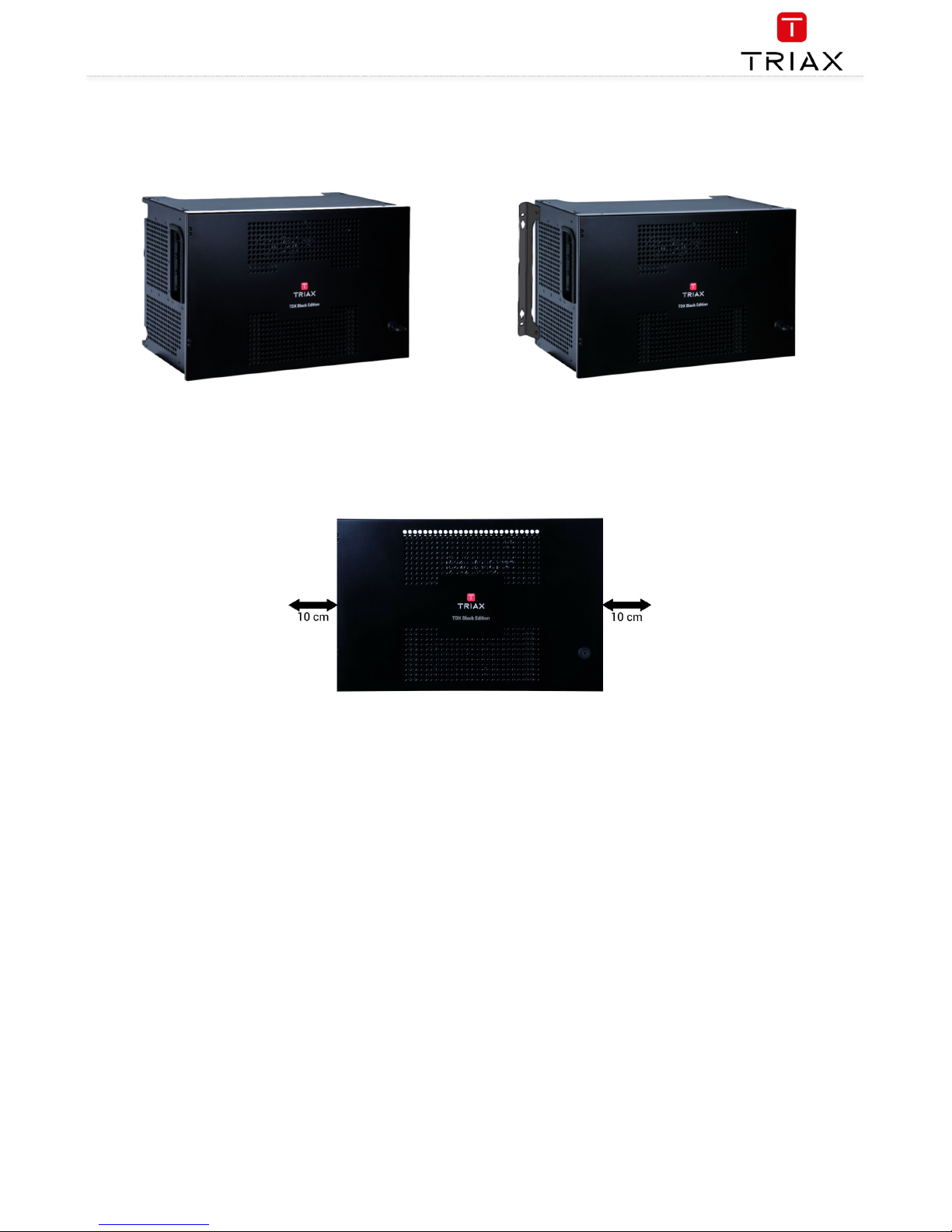
The headend can be mounted either on a system rack or directly onto a wall.
Rack installation Wall installation
1. Attach the mounting brackets to the headend with the supplied screws.
Rack: At the front of a headend
Wall: At the rear of a headend
2. Attach the headend to the wall or onto a system rack
Ventilation requirements
1. Ensure that min. 10cm ventilation space is available on both sides and the front of the headend
2. Insert the key into the headend
3. Open the door
4. Lift the door off its hinges (optional)
5. Remove the top cover (optional)
Power / Earth / ID switch
1. Connect an earth cable to Earth terminal
2. Attach the other end of the earth cable to an approved earth connection point
3. Insert the supplied cable into the Power Input port
4. Confirm that the ID switch is set to “0”
Page 8
TDX Headend System Main Unit
Black Edition
EN
8
Multi Headend installation
Up to three headends can be combined to further increase the number of services provided.
The headends are physically installed as per installation of single headend, i.e. by using the supplied brackets described above.
The headends can be combined in either “direct connection” or “switch connection”
RF output
Connect each headend unit to a combiner using RF cables from the RF output socket to the combiner.
Power
1. Connect each headend unit to an approved ‘earth’ connection point.
2. Provide power to each headend unit with the supplied power lead.
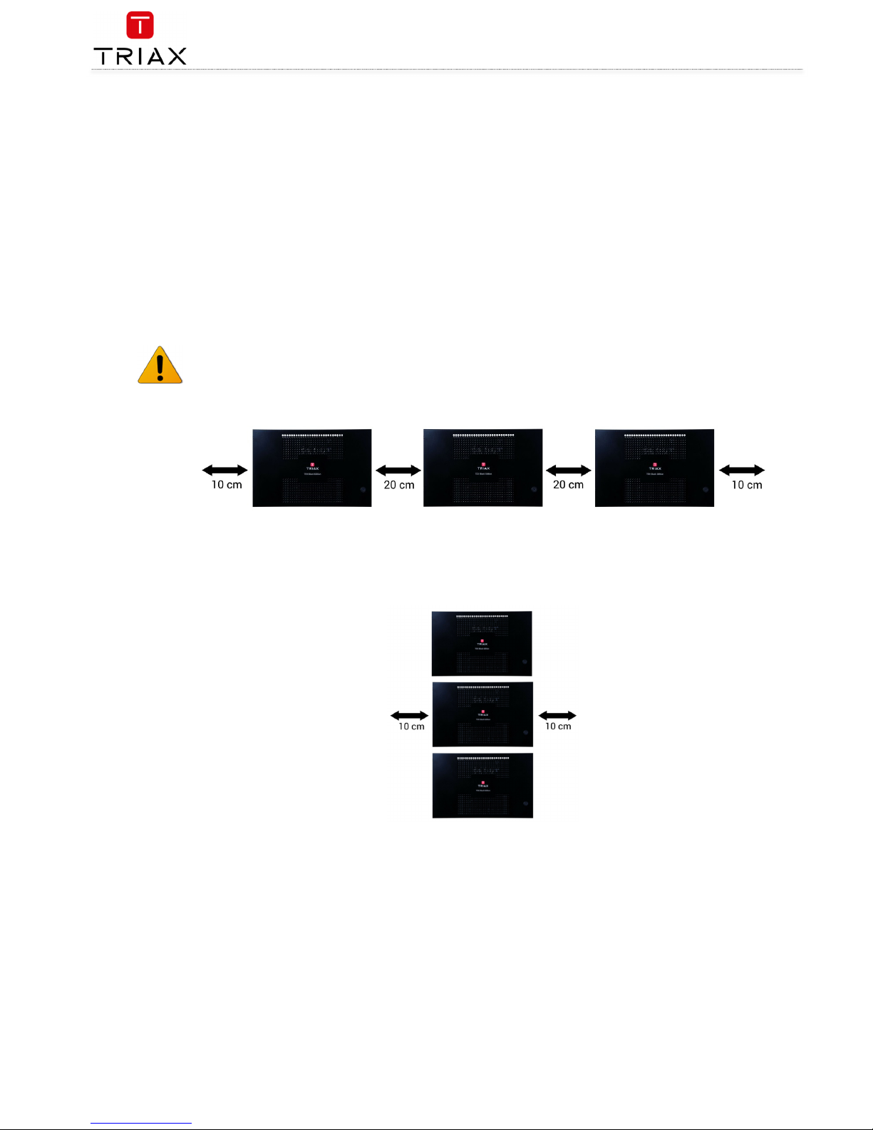
Ventilation requirements
Ensure that the following ventilation requirements are met:
1. Horizontal
Min. 20cm ventilation space must be available between headends.
Min. 10cm ventilation space must be available outside the end headends.
Min. 10cm ventilation space must be available from the front of each headend.
2. Vertical
10cm ventilation space must be available on both sides of each headend.
10cm ventilation space must be available from the front of each headend.
Page 9
TDX Headend System Main Unit
Black Edition
9
EN
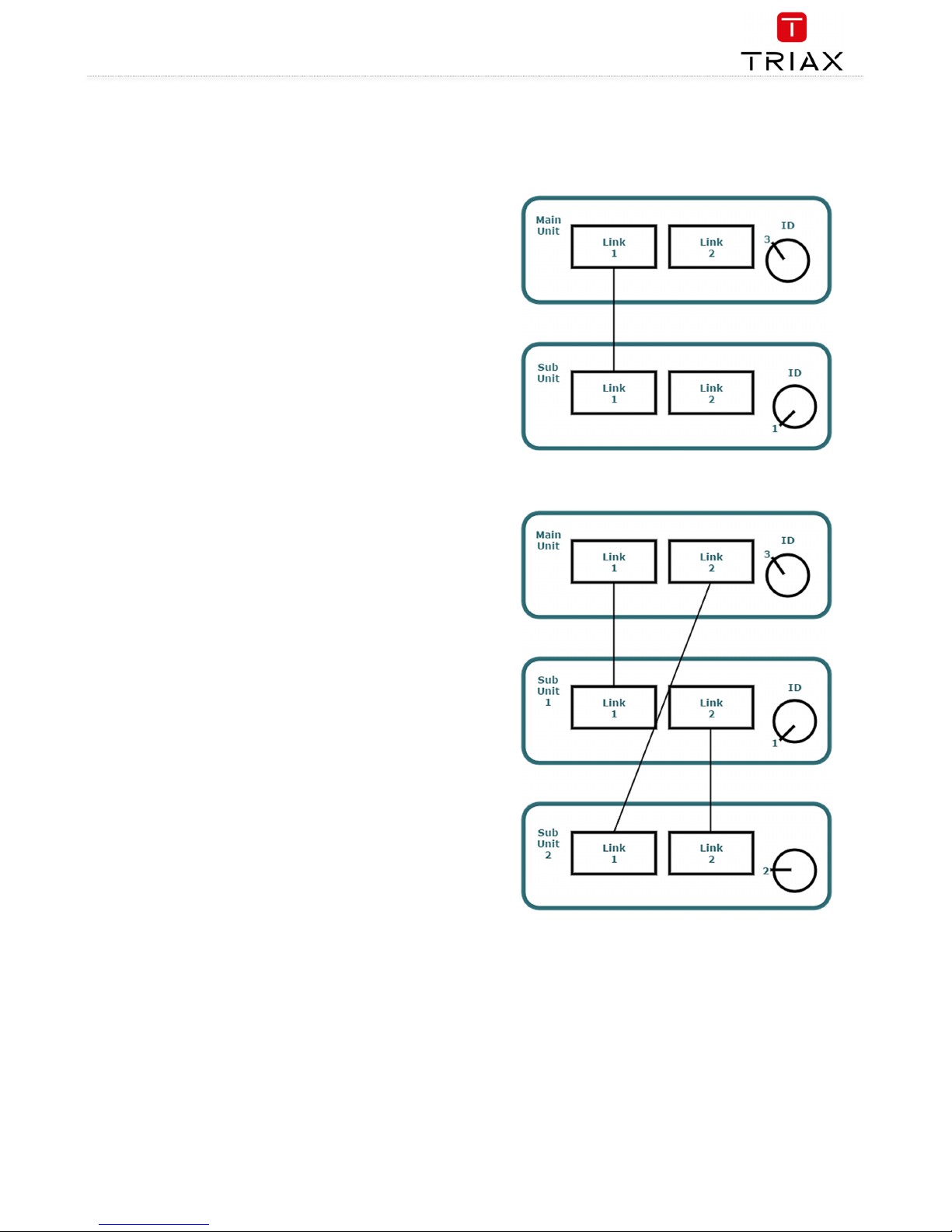
Connection units – direct connection
Note that direct connection hardware configurations require the
Connection type
field in the service tool’s Admin/IP Settings/Setup window
to be set to ‘Direct’
1. 1x Main – 1x sub
1. Insert SFP copper transceivers into the “Link 1“sockets
on the main headend and subunit headend.
2. Route a RJ45 Cat5e or better cable from the "Link 1"
socket on the main unit to the "Link 1" socket on subunit
1.
3. Set the "ID switch" on the main headend and subunit
headend to the following:
Main unit = "3"
Subunit = "1"
a.
2. 1x Main – 2x sub
1. Insert SFP copper transceivers into the “Link 1“ and
“Link 2” sockets on the main headend and subunit
headends.
2. Route a RJ45 Cat5e or better cable from the "Link 1"
socket on the main unit to the "Link 1" socket on subunit
1.
3. Route a RJ45 Cat5e or better cable from the "Link 2"
socket on the main unit to the "Link 1" socket on subunit
2.
4. Route a RJ45 Cat5e or better cable between the “Link 2”
sockets on both subunits.
5. Set the "ID switch" on the main headend and subunit
headends to the following:
Main unit = "3"
Subunit 1 = "1"
Subunit 2 = "2"
Page 10
TDX Headend System Main Unit
Black Edition
EN
10
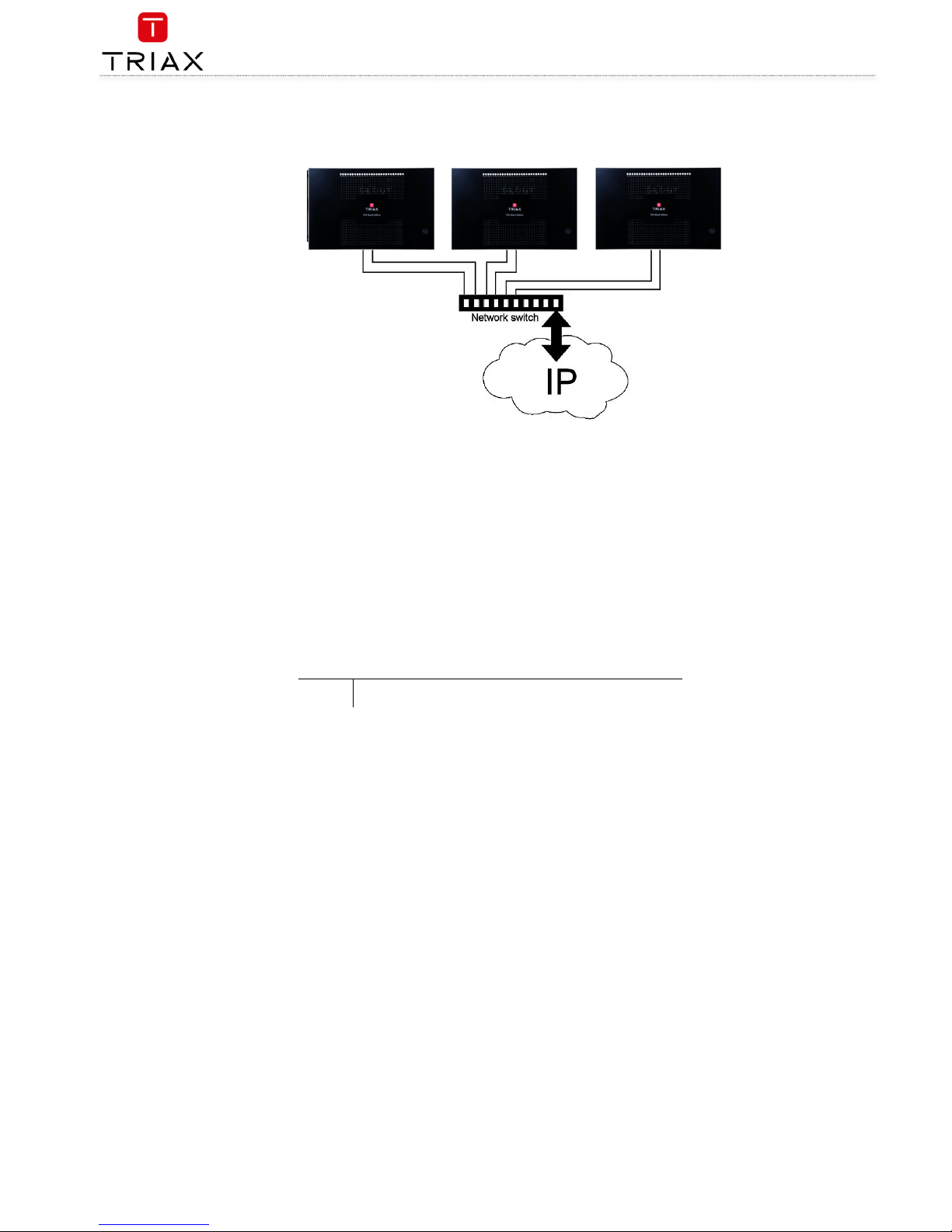
Connecting units – switch connection
Note that headend units connected using a network switch require the
Connection type
field in the service tool’s
Admin /IP Settings
/Setup
window to be set to
Switch
.
Triax recommends that a network switch is used for connecting the main and subunits even if IP services are not currently supported.
The network switch used must support IGMP ver. 2 and contain a sufficient number of ports to connect to the Link sockets on the main
and subunits.
1. Insert SFP copper transceivers into the “Link 1“ and “Link 2” sockets on the main headend and subunit headend(s).
2. Route a RJ45 Cat5e or better cable from the "Link 1" socket on the main unit and subunit(s) to the network switch.
3. Route a RJ45 Cat5e or better cable from the "Link 2" socket on the main unit and subunit(s) to the network switch.
4. Set the "ID switch" on the main headend and subunit headends to the following:
a. Main unit = "3"
b. Subunit 1 to "1"
c. Subunit 2 (if present) to "2"
5. Connect the network switch to the IP network.
Multi headend installation – Fiber optic
Fiber-optic cables must be used to connect the main headend unit to one or two subunits over distances greater than 100m.
The following SFP fibre-optic transceivers must be used in the Link sockets:
492087 Fiber (850nm) (LC) 1000Mbps 550m Gigabit Ethernet
492088 Fiber (1310nm) (LC 1000Mbps 2km Gigabit Ethernet
Resetting IP adress
The IP address of a headend unit can be returned to the factory default address by using the ID switch.
1. Turn off the power to the main unit.
2. Set the ID switch on the main unit to "7".
3. Turn on the power.
The four LEDs flash red and yellow until the process of resetting the IP address has been completed.
The LEDs show green-constant if the reset process was successful.
1. Turn off the power to the main unit.
2. Set the ID switch on the main unit back to the initial setting.
3. Turn on the power to the main unit.
The IP address has been reset to the factory default (192.168.0.100)
Page 11
TDX Headend System Main Unit
Black Edition
11
EN
Input modules
16 input modules can be installed per headend unit. Hot swap technology is used in the headend, meaning that modules can be
inserted/removed/moved when the headend is in operation.
Input module types
Each input module is identified through the use of a specifically coloured label. The label also indicates the module type’s name and associated item
number. The remainder of the label is used for noting post-installation module information.
Another label containing a barcode and serial number is located on the underside of the input module.
Name
DVB-C input module
Item number(s)
492024
Label colour
Crimson
Name
HDMI input module
Item number(s)
492030
Label colour
Orange
Name
A/V input module
Item number(s)
492080
Label colour
Yellow
Name
DVB-S/DVB-S2 input module
Item number(s)
492020
Label colour
Light blue
Name
DVB-T/DVB-T2 input modules
Item number(s)
492022, 492023
Label colour
Purple
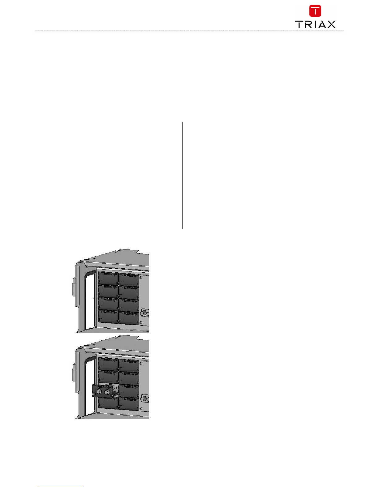
Inserting input modules
Prize the protective cover away from an available input
slot.
Retain the protective cover.
Note: Any available input slot can be used
Push the input module into the input slot until the input
module is locked in position.
Note details for the input module on the label (optional).
Note details for the input module on the label located
inside of the door (optional).
Continue inserting all additional input modules.
Page 12
TDX Headend System Main Unit
Black Edition
EN
12
Attaching cables
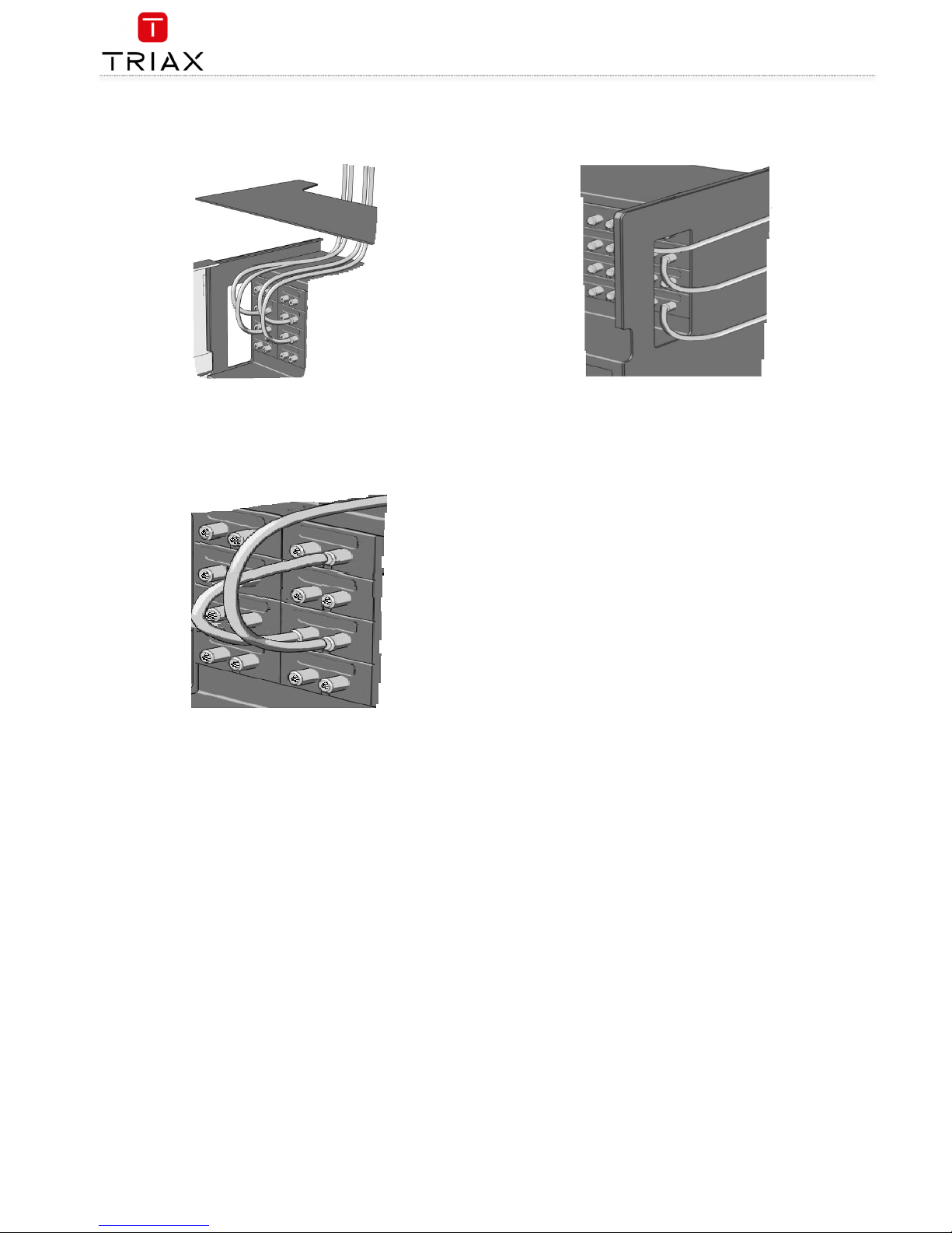
Signal cables can be attached when all input modules have been installed.
1. Route the cables either through the cable openings on the top or on the sides of the headend.
2. Attach the signal cables to the ‘IN’ connector on the input module.
Note:
Ensure that enough cable is available for relocating input modules to alternate input slots at a later date.
Looping cables
DVB-S/S2 signals can be looped between input modules:
1. Attach the signal cable to the IN port on one DVB-S/S2 input
module.
2. Attach a loop cable to the OUT port on the same DVB-S/S2
input module.
Attach the other end of the loop cable to the IN port on another DVBS/S2 input module.*
Removing input modules
Input modules are removed from the headend by:
1. Remove the signal cable from the module.
2. Prize the module out of the headend with a flathead
screwdriver.
3. Pull the module out of the headend.
Note:
Modules can be removed while the headend is in operation.
Moving input modules
1. Prize the module out of the headend with a flathead
screwdriver.
2. Pull the module out of the headend.
3. Insert the module in a new input slot.
Note:
Modules can be moved while the headend is in operation.
Page 13
TDX Headend System Main Unit
Black Edition
13
EN
Output modules
Six output modules, each consisting of four RF channels can be installed in a headend unit. Hot Flash technology is used in the headend, meaning that
output modules can be inserted/removed/moved while the headend is running.
Output module types
Each output module is identified through use of a specifically coloured label. The label also indicates the module type’s name and associated item
number. The remainder of the label is used for noting post-installation module information.
Another label containing a barcode and serial number is located on the underside of the output module.
Name
QAM FTA/CI output module
Item number(s)
492055/492056
Label colour
Purple
Name
PAL FTA/CI output module
Item number(s)
492050/492051/492052/492053
Label colour
Green
Name
COFDM FTA/CI output module
Item number(s)
492060/492061
Label colour
Orange
Name
2xCI Slots output module
Item number(s)
492070
Label colour
Black
Name
IP 2xCI output module
Item number(s)
492072
Label colour
Black
Note:
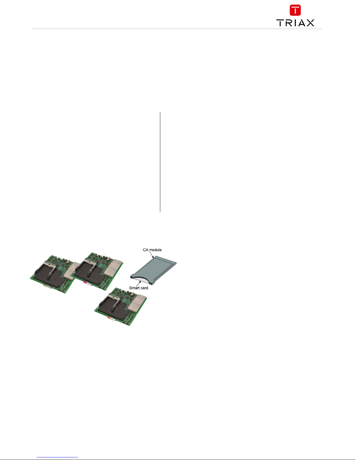
Some output modules also contain slots for two CAM modules
Inserting output module
Depending on where you want to insert the output module push the extractor fan to the opposite side.
1. Insert smart cards (if relevant).
Insert the service provider’s smartcard into the CA
module.
Insert the CA module into either of the available
slots in the output module.
2. Push the output module into an available output slot.
3. Press until the output module is locked into position.
4. Continue inserting all additional output modules.
5. Note details about the output module on the label (optional).
6. Note details about the output module on the label located on
the inside of the door (optional).
7. Return the extractor fan to the centre of the output area.
Removing output module
1. Release the lock mechanism on the module to be removed.
2. Extract the module from the headend.
3. Return the extractor fan to the center of the output area.
Auxiliary modules
Two slots are present in the middle of the output section for installation of auxiliary modules. For details refer to products that use auxiliary boards.
Page 14
TDX Headend System Main Unit
Black Edition
EN
14
System monitoring
Input modules – LED status
Each input module has an LED on the front to
indicate its current status when the headend is
powered:
Green - flashing
The module is yet to be configured yet.
Green
No errors, and the tuner is locked to the frequency.
Red
Error, and the tuner is not locked to the frequency.
No colour
Module is not powered.
Input module software updates are also displayed
on the LED when the modules are updating:
Orange
Booting.
Temporary off
Initiation of the software update.
Temporary green
Every time the module receives a valid data package.
Repeated until the update is completed without errors.
Red
Software update failed.
Output modules – LED status
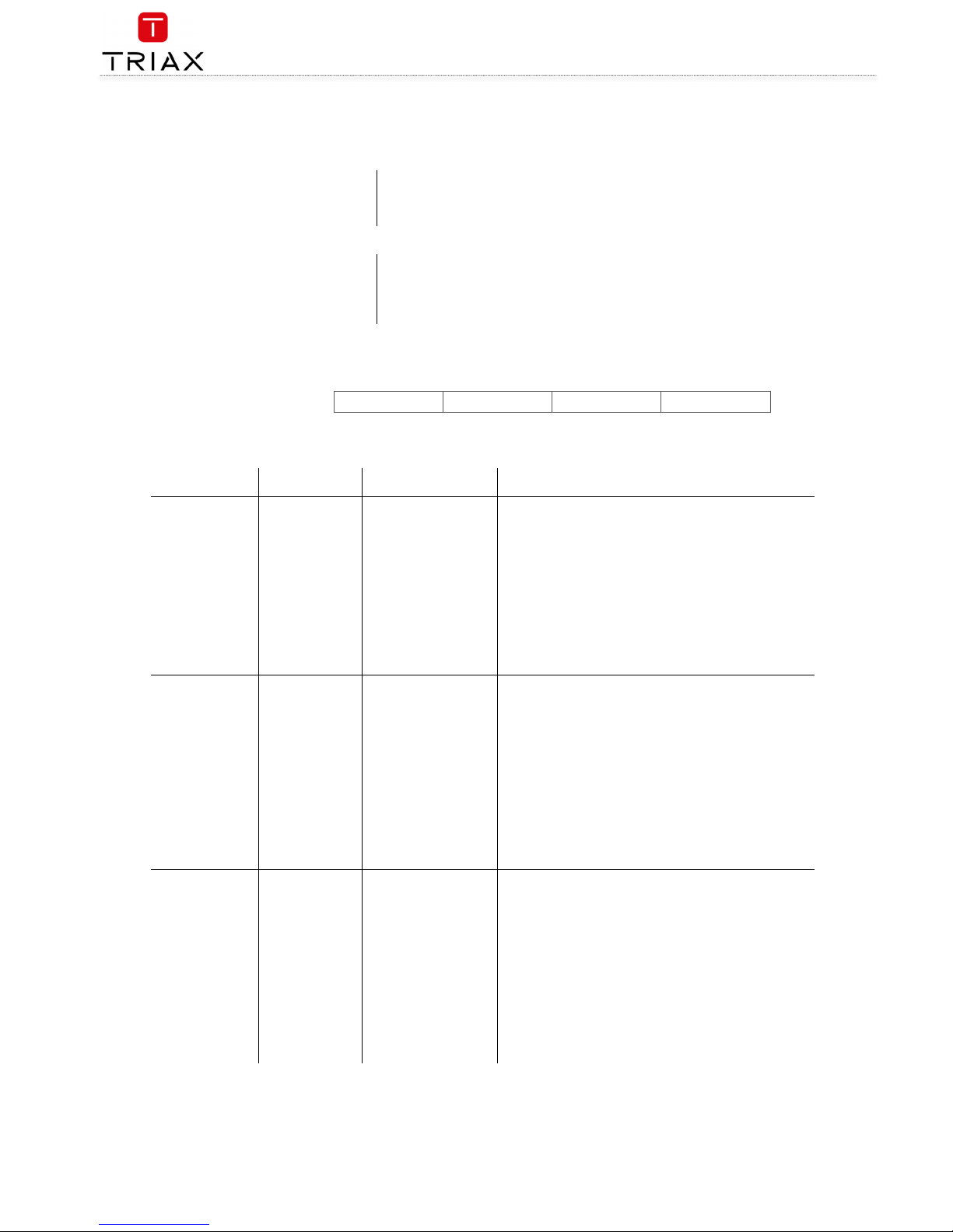
Four LEDs are placed at the top of the output section of each headend unit, and provide information on the state of the
headend and subunits (if present).
The four LEDs are named (from left to right):
The LEDs can be green - constant, green – flashing, red, or no colour is displayed. The message being indicated are different for each LED.
Headend
type/usage
LED Name Colour Message
Standalone System Status
Green – constant Power is on and the headend is operational.
Green – flashing The headend is booting up.
Red
An error has been detected in the headend, which must be
investigated.
Tuner Status
Green – constant The input module tuners are locked.
Red One or more Input module tuners are not locked.
Unit Link 1 Not used
Unit Link 2 Not used
Main Unit in
multi-unit
installation
System Status
Green - constant
Power is on and the headend is operational.
Green – flashing The headend is booting up.
Red
An error has been detected in the headend, which must be
investigated.
Tuner Status
Green – constant The input module tuners are locked.
Red One or more Input module tuners are not locked.
Unit Link 1
Green – constant The subunit is connected to the main unit.
Red There is a problem with the connection to the subunit.
No colour No subunit is connected to the main unit.
Unit Link 2
Green – constant The subunit is connected to the main unit.
Red There is a problem with the connection to the subunit.
No colour No subunit is connected to the main unit.
Sub Unit 1 in
multi-unit
installation
System Status
Green – constant Power is on and the headend is operational.
Green – flashing The headend is booting up.
Red
An error has been detected in the headend, which must be
investigated.
Tuner Status
Green – constant The input module tuners are locked.
Red One or more Input module tuners are not locked.
Unit Link 1
Green – constant The subunit is connected to the main unit.
Red There is a problem with the connection to the subunit.
No colour No subunit is connected to the main unit.
Unit Link 2
Green – constant The subunit is connected to the main unit.
Red There is a problem with the connection to the subunit.
No colour No subunit is connected to the main unit.
System Status Tuner Status Unit Link 1 Unit Link 2
Page 15

TDX Headend System Main Unit
Black Edition
15
EN
Headend
type/usage
LED Name Colour Message
Sub Unit 2 in
multi-unit
installation
System Status
Green – constant Power is on and the headend is operational.
Green – flashing The headend is booting up.
Red
An error has been detected in the headend, which must be
investigated.
Tuner Status
Green – constant The input module tuners are locked.
Red One or more Input module tuners are not locked.
Unit Link 1 Green – constant The subunit is connected to the main unit.
Red There is a problem with the connection to the subunit.
Unit Link 2
No colour
No subunit is connected to the main unit.
Green – constant The subunit is connected to the main unit.
Red There is a problem with the connection to the subunit.
No colour No subunit is connected to the main unit.
Service tool - System requirements
The headend needs to be configured before it can be used.
Computer minimum requirements
A computer meeting the following minimum requirements is required for configuring the headend.
Operating system:
Windows XP or later
Browser:
Mozilla firefox ver. 46.0.1 or newer
Google Chrome ver. 50.0.2661 or newer
MS internet explorer 11 ver. 11.0.9600.18314 or newer
Static IP address
A static address must be used on the computer you use to configure the headend.
Refer to the computer’s operating software documentation for assistance on using static IP addresses.
Page 16
TDX Headend System Main Unit
Black Edition
EN
16
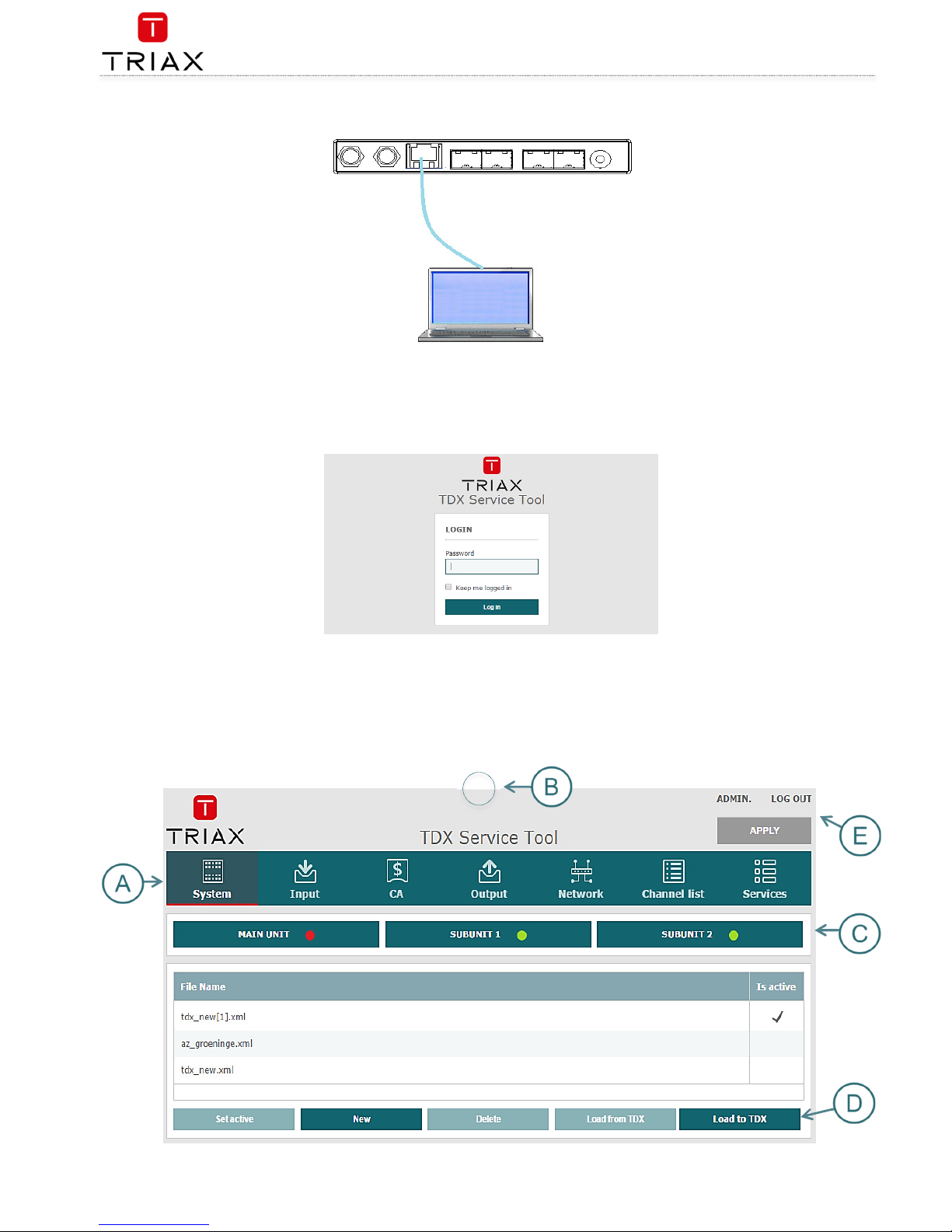
Physical connection to headend
Connect a Cat5e shielded cable or better between the computer’s network port and the configuration port on the headend.
Starting service tool
1. Open a web browser window.
2. Enter
‘http://192.168.0.
100’ in the web address field.
3. Press
Enter
.
4. Enter the password.
5. Press the
Log in
button.
Note:
Password = ‘
triax1234’
when the service tool is opened on each headend for the first time.
The
Keep me logged in
checkbox overrides the system’s automatic time out function, which is activated after 20 minute’s inactivity.
Overview
Page 17
TDX Headend System Main Unit
Black Edition
17
EN
Tabs
Accesses the various tabs used to configure the headend’s input and output modules.
System
The service tool’s ‘home’ window. Provides system overview information and
configuration activation/control.
Input
Tab for configuring input modules and services.
CA Modules
Tab for configuring CI modules and CA cards. Refer to output module manuals for
information.
Output Network
Tab for configuring output modules and services.
Channel List
Tab for viewing available channels, refer to input module manuals for information.
Services
Tab for service overview with filter options
Communication circle
Indicates whether the service tool is communicating with the headend unit.
Circle is spinning
The service tool and headend are communicating.
System icons
Indicates whether the headend unit is functioning correctly.
Green
The headend unit is functioning correctly.
Red
The headend unit is NOT functioning correctly.
To get further information: press relevant button :
Main unit
Subunit 1
Subunit 2
Misc. buttons
Apply
Stores and applies the configuration settings.
Log In/Out
Service tool access control.
Admin
Opens the settings for service tool window, where language, location, time zone, and
initial IP addresses are specified.
Configuration buttons
Set active
Set the selected configuration active
New
Create a new default configuration
Delete
Delete the selected configuration
Load from TDX
Load new configuration from computer
Load to TDX
Load selected configuration to computer
Administration
NOTE:
Press checkmark to select configuration.
Page 18
TDX Headend System Main Unit
Black Edition
EN
18
The system language, locale, and time zone need to be specified on each headend unit.
It is also necessary to specify IP addresses for headends which are located on a distribution network.
Language
1. Press the
Admin
button at the top right-hand corner of the
System window.
2. Open the
Current language
drop-down list.
3. Select the desired language.
4. Press the
UPDATE
button, down below.
Location
1. Press the
Admin
button at the top right-hand corner of the
System window.
2. Expand the
Country settings
area.
3. Open the
Current location
drop-down list.
4. Select the country where the headend is located.
5. Press the
UPDATE
button, down below.
Time zone
Page 19
TDX Headend System Main Unit
Black Edition
19
EN
1. Press the
Admin
button at the top right-hand corner of the
System
window.
2. Expand the
Time zone settings
area.
3. Open the
Input module (Main unit)
drop-down list.
4. Select the input module that is to be used for setting the
headend’s system date/time/time zone.
5. Press the
UPDATE
button, down below.
Time set by NTP server
It is possible to have the time in the TDX set by a NTP server.
The
Primary
and
Secondary time server
can be setup using either a. IP
address like “192.168.30.31” or a URL like “the.best.ntpserver.org”. If a
URL is used then a DNS must be setup in the
IP settings
sub menu. See
below.
Security
1. Press the
Admin
button at the top right-hand corner of the
System window.
2. Expand the
Password settings
area.
3. Specify the current password in the
Old password
field.
(‘
triax1234’
) if the service tool is being used for the first time.
4. Specify a new password in the
New password
field.
5. Re-specify the new password in the
Confirm password
field.
6. Press the
UPDATE
button, down below.
Page 20
TDX Headend System Main Unit
Black Edition
EN
20
Features
and License Keys
Licenses handle the Features (e.g. IP input and/or IP output or SNMP
functionality) available for the Headend. To activate a specific
Feature, you need to type in the License Key for the specific Feature.
The License Key and matching Unique ID is created for the individual
Headend, and can therefore not be re-used in other Headend
installations.
When you have purchased and retrieved the necessary License Keys
and Unique IDs they need to be entered into the Headend system to
activate the Feature:
1. Press the Admin button at the top right-hand corner of the
system window.
2. Expand the “License handling” area.
3. Enter the retrieved License Keys to the matching Unique
IDs in the order given from TRIAX.
4. Press the ACTIVATE button, and the installed license is
listed.
How-To get
License Keys
To retrieve a License Key, you need to access the TRIAX Product
Registration Tool (PRT) on our online HELPDESK:
http://www.triax.com/Helpdesk/ProductRegistrationTool
To register a Headend system and retrieve new License Keys, you will
need to upload the Equipment-File for the specific Headend. The
Equipment-File is automatically generated by the service tool:
1. Press the Admin button at the top right-hand corner of the
system window.
2. Expand the “System maintenance” handling area.
3. Press SAVE EQUIP. and the Equipment-File is generated and
saved on your PC.
30-day Trial Period, Free of charge access to all Features
The TDX Black Edition is delivered with a free of charge 30-day
installation period with unlimited access to all available Features.
When TDX Black Edition is initialized for the first time, you have to start
the 30-day Trial Period. The START TRIAL box is automatically displayed,
and you start the trial by pressing START.
Above the menu bar you will now see the remaining days of your trial
period.
To activate Features permanently, please follow procedure described in
“Features and License Keys”
To end 30-day Trial Period actively you have 2 choices:
1. Retrieve “Installation Key” license from PRT. At the same time
please retrieve License Keys for any other Features to be
permanently installed in the Headend.
2. Expand “License handling” area and press END TRIAL.
NOTE:
Access to TRIAX HELPDESK require personal login credentials! If
not already acquired, please apply online on
http://www.triax.com/Service/UserSubscriptionSLA
Attention
When trial period reaches 0 days, the Headend will automatically
restart and no
Features
will be available.
.
Page 21
TDX Headend System Main Unit
Black Edition
21
EN
IP
settings
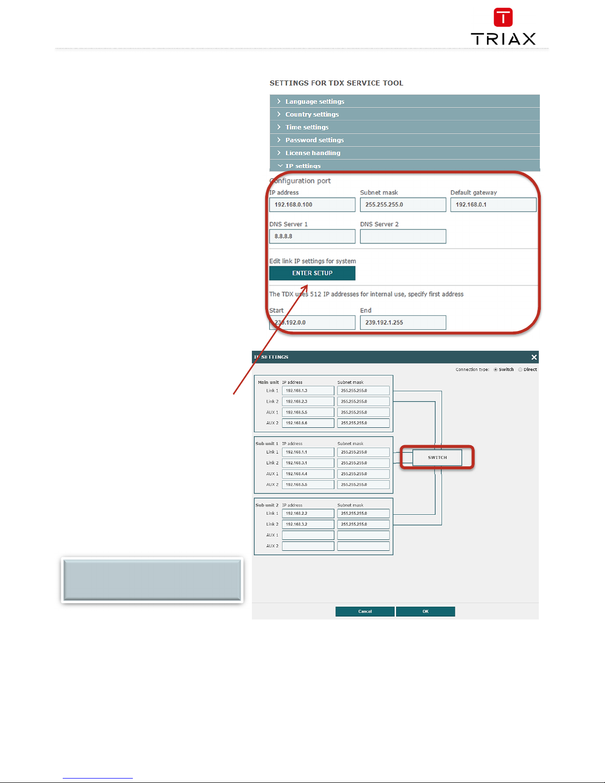
It may be necessary to specify specific IP addresses for the
headend to avoid network IP address conflicts.
Note:
Headend IP addresses can be reset to factory default
settings if required. This is done via the ID switch located on
the headend unit(s).
1. Press the
Admin
button at the top right-hand
corner of the System window.
2. Expand the
IP settings
area.
3. Specify the headend’s IP address, subnet mask
and default gateway in the corresponding fields.
4. Press the
UPDATE
button, down below.
IP settings
- continued
This step is only relevant where Main and sub units are
connected to the network via a Gigabit network switch.
1.
Press the
ENTER SETUP
button
The
IP Settings
window is used to specify unique IP
addresses and subnet masks used by the Link 1 and
Link 2 sockets on the main and sub units. This provides
additional functionality to avoid IP address conflicts.
1. Select the
Switch
radio button.
2. Specify unique IP addresses and subnet
mask details for the main and subunits in the
corresponding fields.
3. Press the
UPDATE
button, down below.
NOTE:
The
AUX 1, AUX 2
and associated
IP Address
and
Subnet mask
fields are used in connection with the
IP output module
.
Page 22
TDX Headend System Main Unit
Black Edition
EN
22
IP
settings
-
continued
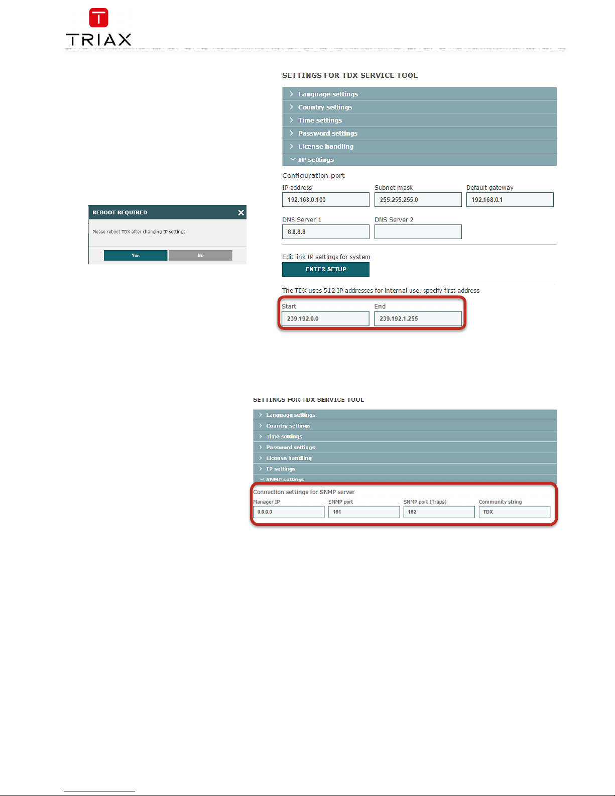
Remaining steps are valid for all multi-unit installations.
The 512 IP addresses used by the headend(s) must not
conflict with any of the IP addresses used either within the
network or for services.
1. Enter the first of the 512 IP addresses used for
internal purposes in the
Start
field.
2. Press the
UPDATE
button, down below.
A message is displayed if the headend needs to be rebooted
due to IP address changes having been made.
SNMP settings
SNMP stands for “Simple Network Management
Protocol”.
SNMP is an Internet standard protocol that you use
for exchanging management information between
the equipment in a CATV network. You can use
SNMP to monitor sub-headends, fibre notes and
amplifiers or to check the status of the equipment.
1. Press the
Admin
button at the top right-
hand corner of the System window.
2. Expand the
SNMP settings
area.
3. Specify the IP address of the computer
that monitors the network, i.e. the SNMP
manager.
4. Specify new SNMP port numbers if you
want to change the default values in the
two SNMP port fields.
5. Enter a password to access the SNMP
manager in the
Community string
field.
6. Press the
UPDATE
button, down below.
For an overview of SNMP traps, see “SNMP Traps”.
Page 23
TDX Headend System Main Unit
Black Edition
23
EN
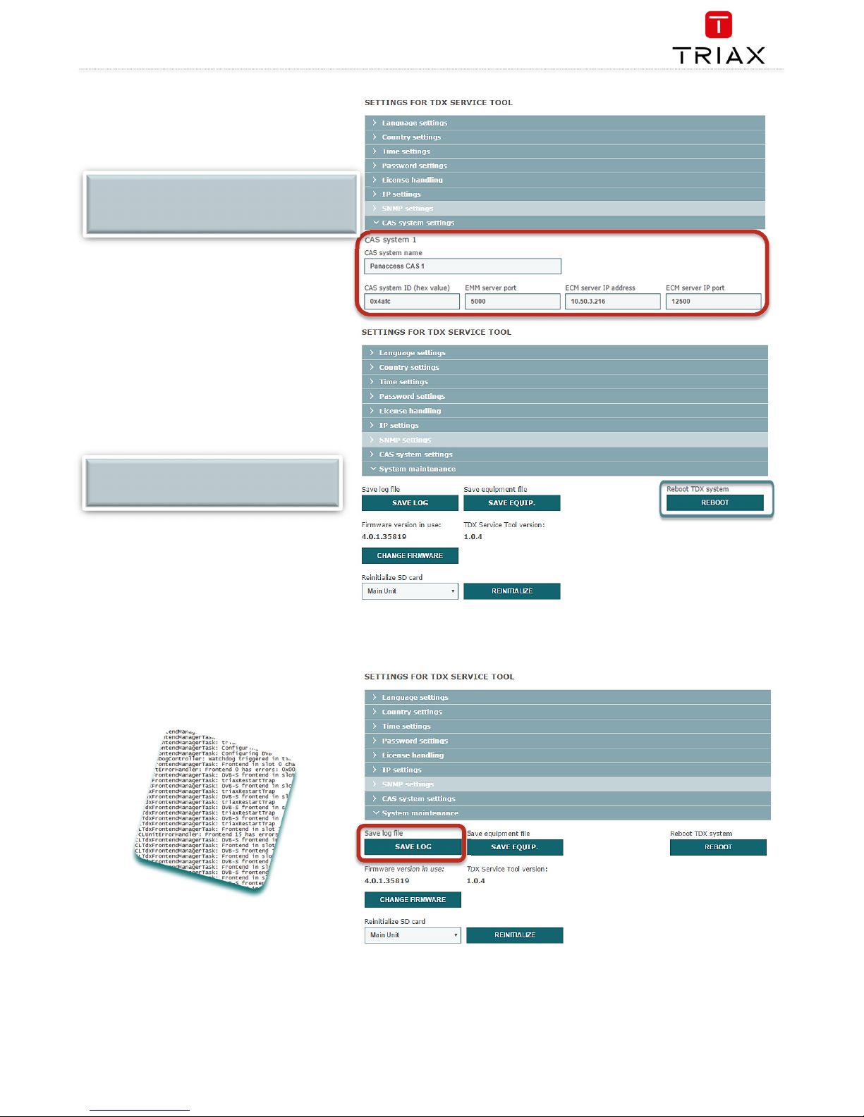
CAS server settings
Enter relevant information – as example
shown here.
Press the
UPDATE
button, down below.
Rebooting
1. Press the
Admin
button at the top of the right-
hand corner of the System window.
2. Expand the System maintenance area.
3. Press the
Reboot
button.
4. You will be prompted before reboot takes
place.
View
system log
It is possible to save log files for viewing headend
actions.
1. In the System maintenance – press
SAVE LOG
2. A txt file is saved to the Downloads folder in
Windows – see snippet above.
3. Open the TDXLOG.txt file in ie. Notepad or the
like.
4. Rename the file if needed
NOTE:
CAS system should be connected to the TDX system.
TDX should have quality input signal and user should
have a license.
NOTE:
Changes to IP addresses only take effect when the
headend has been rebooted.
Page 24
TDX Headend System Main Unit
Black Edition
EN
24
Firmware updating
Firmware updates are available from the support/
helpdesk sites at TRIAX
Always read the release notes to determine whether the
headend would benefit from available firmware updates
or not.
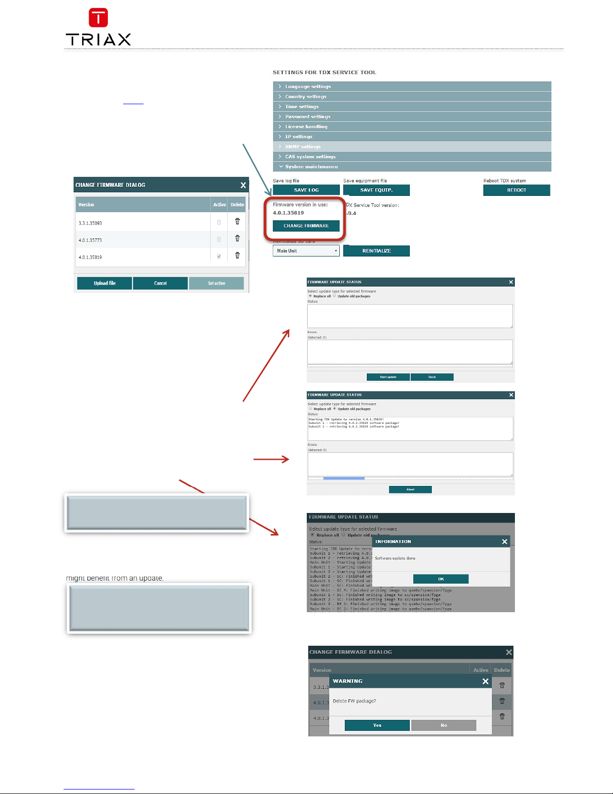
1. Press the CHANGE FIRMWARE button
2. A dialog box that lists the current and previous
F/W versions, will open:
3. To change the F/W, highlight the firmware you
want to install, press SET ACTIVE or
Press the UPLOAD FILE button, find the desired
F/W to be uploaded and installed, and then
press SET ACTIVE
4. When you have pressed the the SET ACTIVE
button a box opens, where you have 2 options:
a. REPLACE ALL
updates all of the headend’s firmware, i.e.
modules, system controller and user interface.
(This is recommended)
b. UPDATE OLD PACKAGES
Updates only outdated modules
5. Press START UPDATE, and the update starts,
during which you have can abort if needed.
6. When update is finished (could take some time)
you will be noticed.
The
Update old packages
radio button should only be
used in cases where the headend consists mainly of new
modules, but also contains some older modules that
might benefit from an update.
Firmware clean
up
Select the firmware updates to be removed from the
system tool by pressing the DELETE bucket, and confirm
with YES
NOTE:
Service distribution to end-users will be disrupted
while the headend restarts.
S/W NOTE:
As from the F/W version 4.0.1 it is not possible to
reverse to older Firmware. This is due to
significantly changed and improved firmware.
Page 25
TDX Headend System Main Unit
Black Edition
25
EN
Format file system in flash
Force TDX
systemcontroller in failsafe mode
If data in the TDX needs to be deleted, then you need to format file
system in flash of the TDX.
Be aware: this operation DELETES ALL data in the TDX
– including License data !
1. Set rotary wheel to 6
2. Reboot TDX
3. Wait for the 4 front LED’s to blink red
4. Set wheel to 2
5. The 2nd diode should slowly blink green followed by rapid
blinking green after some seconds
6. Wait for diode to turn solid green
7. Set wheel back to original position
8. Reboot
If there is a S/W version mismatch inside the TDX system – then the
system will go into “Failsafe” mode. To get back into normal mode, a
S/W update has to be performed.
The Failsafe mode can also be forced – see description below:
1. Set rotary wheel to 6
2. Reboot TDX
3. Wait for the 4 front LEDS to blink red
4. Set wheel to 1
5. The 1 st diode should slowly blink followed by fast blinking
green
6. Wait for diode to turn solid green
7. Set wheel back to original position
8. Reboot
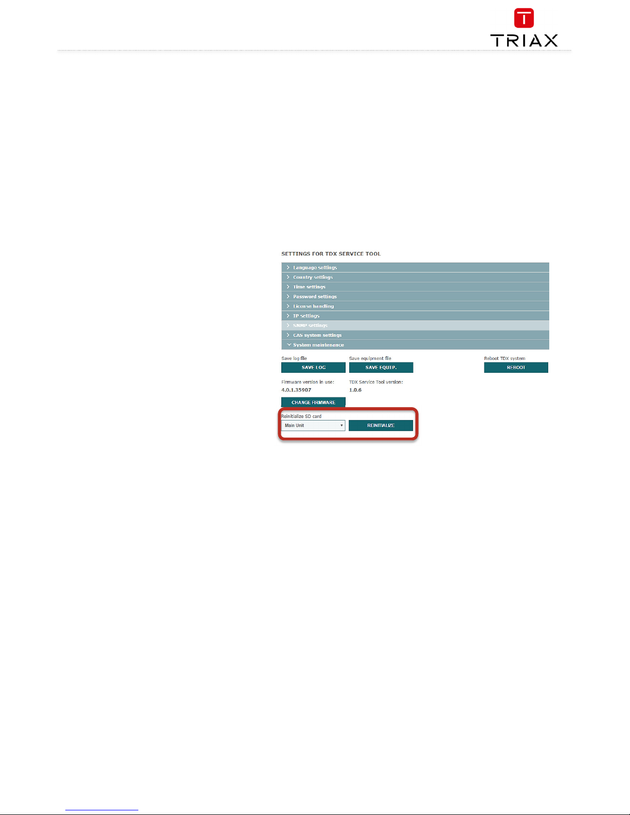
Reinitialize SD card
If the TDX system reports “SD card corrupt” then the SD
card needs to be reinitialized.
This can happen for the SD card in either the Main or
Subunit 1 or 2. (if your TDX system got Subunits)
Be aware: This function deletes ALL information stored in
the SD card.
The SD card stores NON critical data, (ie. logfiles and S/W
update packages).
Choose the unit in which the SD card needs to be
reinitialized.
Page 26
TDX Headend System Main Unit
Black Edition
EN
26
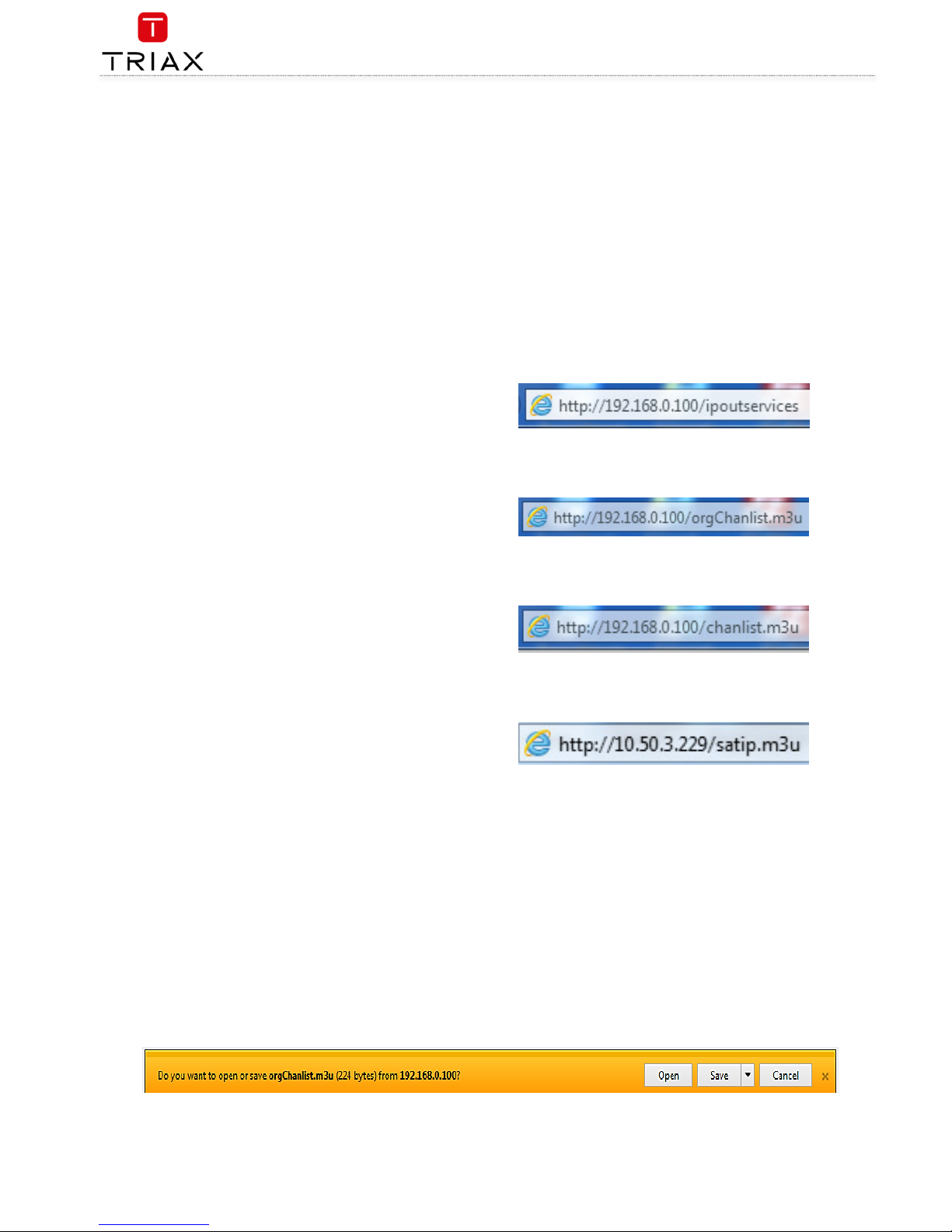
IP out service list
It is possible to get the list of services at IP out in the following
formats:
XSPF
M3U
Extended M3U
Extended++ M3U
XSPF
can be accessed by enter “/ipoutservices” after the URL for
the TDX configuration.
Sample
:
<?xml version="1.0" encoding="UTF-8"?>
<playlist version="1" xmlns="http://xspf.org/ns/0/">
<trackList>
<track><title>DR1</title><location>udp://@239.194.0.1:50172</location>
<extension
application="http://www.triax.com"><poolserviceid>4</poolserviceid></extension></track>
<track><title>Syd</title><location>udp://@239.194.0.2:50172</location>
<extension
application="http://www.triax.com"><poolserviceid>6</poolserviceid></extension></track>
</trackList>
</playlist>
M3U
can be accessed by enter “/orgChanlist.m3u” after the URL for
the TDX configuration.
This service list contains
IP adresses and port numbers
Sample:
udp://239.194.0.1:50172
udp://239.194.0.2:50172
Extended M3U
can be accessed by enter “/chanlist.m3u” after the
URL for the TDX configuration.
The service list is compliant to SAT>IP Protocol Specification
(ver. 1.2.2) and is defined as
“extended M3U channel list”
In the standard under appendix A2.1
This service list contains
IP adress and port number
Service name
LCN
Sample
:
#EXTM3U
#EXTINF:0,1. DR1
udp://239.194.0.1:50172
#EXTINF:0,3. Syd
udp://239.194.0.2:50172
Extended++ M3U
can be accessed by enter “/satip.m3u” after the
URL for the TDX configuration.
The service list is based at the Extended M3U with further
extensions.
The service list can be used for TV sets. Panasonic is one TV set
vendor that supports this service list as service discovery.
The list is used for communication between the TDX system
controller and the TDX EPG server.
This service list contains
IP adress and port number
Service name, transport stream ID, original network ID
LCN
Service type (1=TV, 2=Radio)
Sample
:
#EXTM3U
#EXTINF:0,1. DR1
udp://239.194.0.1:50172?stype=1&onid=43962&tsid=0&svcid=4
#EXTINF:0,3. Syd
udp://239.194.0.2:50172?stype=1&onid=43962&tsid=0&svcid=6
All above list will be downloaded:
Page 27
TDX Headend System Main Unit
Black Edition
27
EN
System information
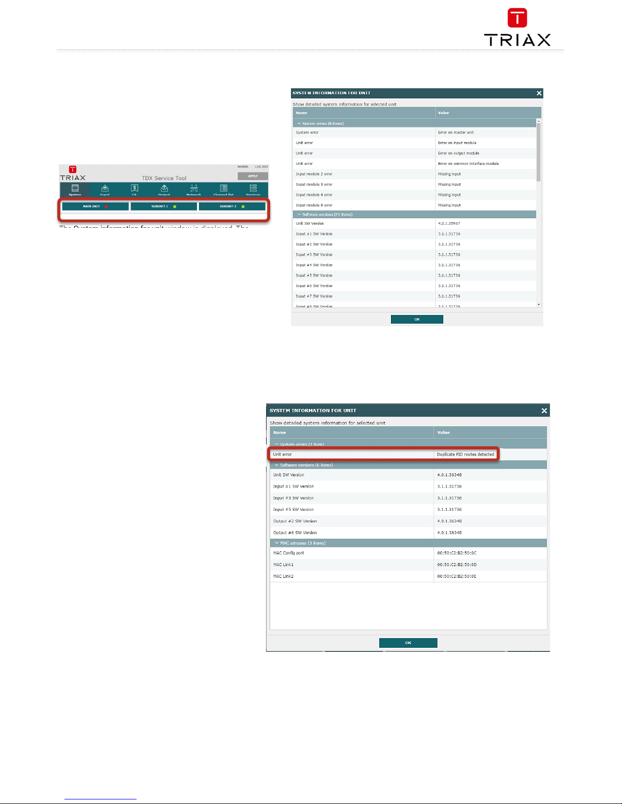
Duplicated PID‘s
Selecting IP services for output may result in a selection
of services from an MPTS stream that uses the same PID
for two or more services.
It is not possible to output services with identical PIDs.
If you have selected services with identical PIDs, the
System icon of the headend unit that handles the output
of the services with identical PIDs turns red.
Click the affected unit to open the
System
information for unit
window.
The
System information for unit window
lists the output
module(s) and channel(s) which attempt to output
services with identical PIDs.
To solve the problem you have to open the configuration
window of the output module(s) listed in the
System
information for unit
window, and deselect the selected IP
services one by one while checking the
System
information for unit
window until the message disappears
from the window.
Viewing
system information
Detailed information is available on headend units:
1. Select the
System
tab.
2. Select the main unit or one of the subunits in the
System information list
area.
The
System information for unit
window is displayed. The
window contains information relating to:
Any headend system errors
Name and associated software version of input and output
modules
Note that the software versions installed on all headends,
including each input/output module must be identical.
Update the software for the entire headend installation
(including input/output modules) if this is not the case.
MAC addresses
Current/minimum/maximum temperatures
Power supply
Page 28
TDX Headend System Main Unit
Black Edition
EN
28
Managing configuration files
Creating
1. Select the
System
window.
2. Select the
New
button.
An empty configuration file is created and listed in the
configuration list area.
Activating
1. Select the
System
tab.
2. Select the configuration that is to be actively
used on the headend.
Press the
Set active
button.
Deleting
1. Select the
System
tab.
2. Highlight the configuration file to be deleted.
Press the
Delete
button.
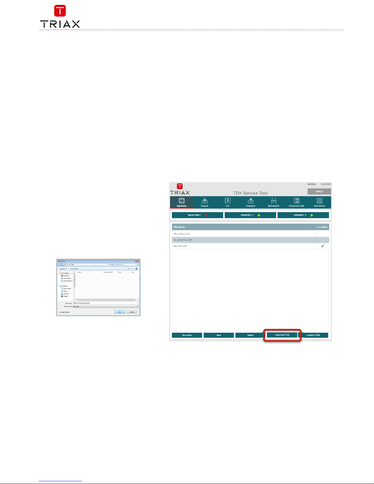
Saving
Headend configuration files can, if desired, be saved on
the computer. This simplifies the process of configuring
additional headends that contain the same modules.
A saved configuration file can also be used on headends
that do not contain exactly the same modules. It will,
however, be necessary to reconfigure/delete/add the
modules that differ between the initial headend and that
being configured.
1. Select the
System
tab.
2. Press the
Load from TDX
button.
3. Navigate to where the configuration file is to be
saved.
4. Enter a name for the configuration file.
5. Select ‘XML’ in the
File type
field.
6. Press the
Save
button to save.
Page 29
TDX Headend System Main Unit
Black Edition
29
EN
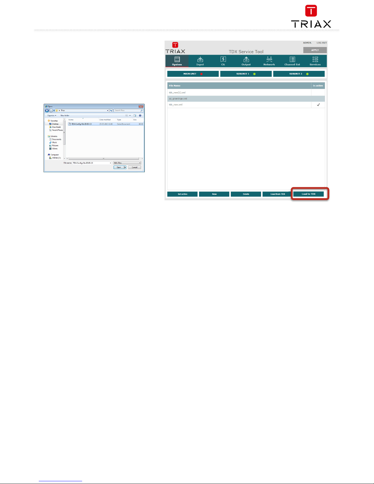
Uploading
Configuration files previously saved on a computer can be
transferred to the system tool to simplify the
configuration process.
Any module differences will need to be manually
configured.
1. Select the
System
tab.
2. Press the
Load to TDX
button.
3. Navigate to the folder where the configuration
file to be uploaded is located.
4. Select the file.
5. Press the
Open
button.
The configuration file will now be listed in the
configuration list area. A number in brackets, e.g. (1), is
added to the name of the new file if an identically named
configuration file is already present.
Page 30
TDX Headend System Main Unit
Black Edition
EN
30
IP Input configurations
The headend system includes basic IPTV functionality which enables service delivery over a packet-switched network infrastructure. To handle IP input
through the Link sockets the following requirements must be satisfied:
IP multicast streaming (UDP streaming)
Possibility of RTP
Possibility of IGMP version 2
SPTS or MPTS including PAT, PMT, CAT
Important:
The TDX headend system supports up to 7 TS packets per IP packet at IP inputs.
The TDX headend system does not support IP fragmentation at IP inputs, which may occur if the IP packets are transmitted over a network with a
Maximum Transmission Unit (MTU) less than approximately 80 + N*188 bytes, where N is the number of packets per IP packet..
Recommended settings are 7 TS packets per IP packet and a minimum MTU of 1500 bytes in the entire network path.
Creating
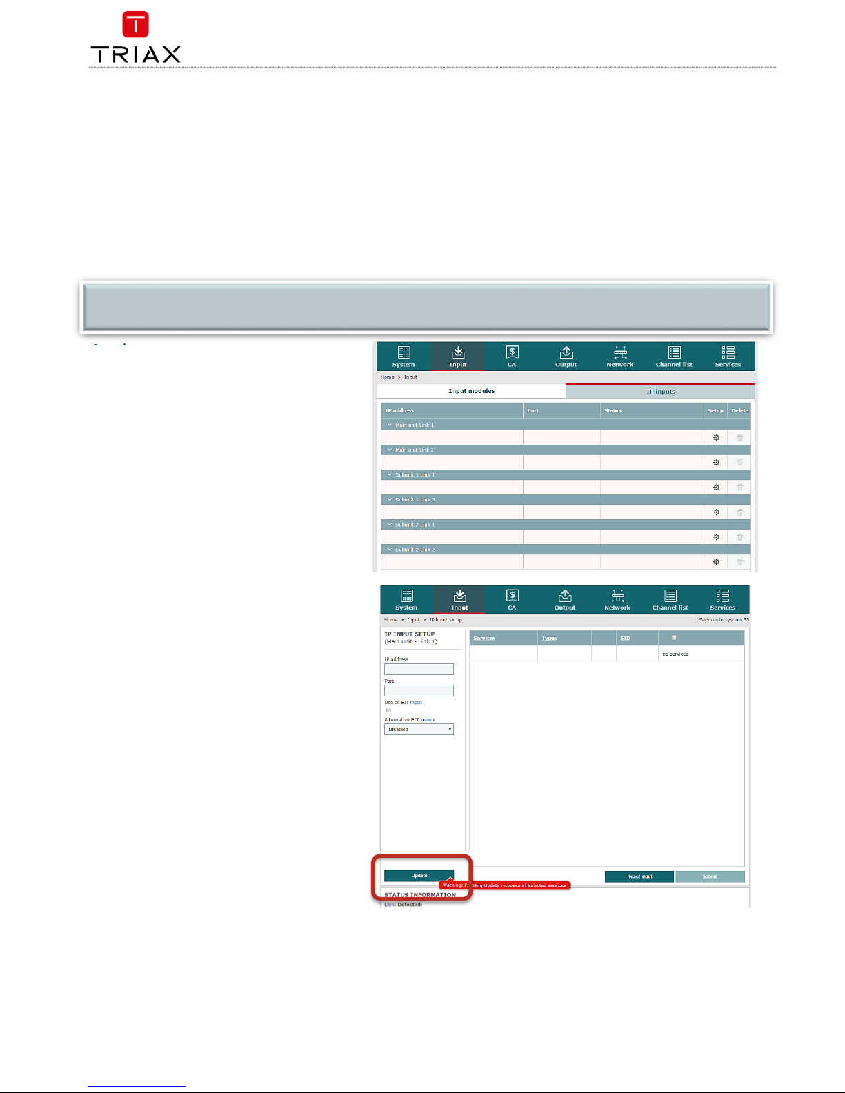
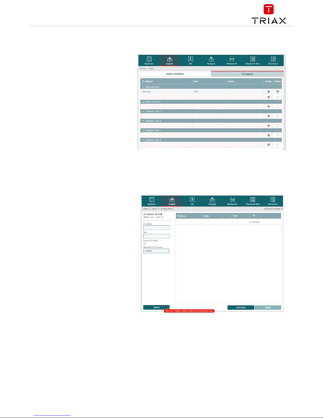
1. Select the
Input
tab.
2. Select the
IP inputs
sub-tab.
3. Press the
Setup
button for the link socket that
processes IP input.
4. Specify the desired IP address and associated
IP port number in the corresponding fields.
5. Press the
Update
button.
6. Check the
Selected services
checkbox for one
or more services to select the service(s) you
want to use.
NOTE:
Licenses for IP input are required to be able to use the IPTV functionality in the headend. The licenses can be purchased from Triax Sales, and need
to be activated, see “Activating licenses”.
Page 31
TDX Headend System Main Unit
Black Edition
31
EN
Creating
- continued
Important:
If the IP input uses MPTS streams, then each stream can
contain one or more services. An MPTS stream may use
the same PID (Package ID) for two or more of the
services that it contains.
However, the headend system cannot output services
with the same PID. To discover services with the same
PID is NOT possible until you have selected the services
with identical PIDs in order to output them using an
output module or a Link socket.
If you attempt to output services with identical PIDs:
the System Status LED turns red on the unit
that tries to output the IP services,
the System icon of the affected headend unit
turns red on the System tab in the Service Tool,
the System Status LED and System icon turn
red on the main unit in a multi-unit installation.
See “Duplicated PIDs” for further information.
7. View the
Status information
area to ensure that
IP data is being sourced through the Link
socket.
8. Press the
Submit
button.
The selected service is now available in the headend
service pool.
9. Press the Apply button to save the new
settings in the configuration.
Specifying EIT/EPG source
One input on each link per headend can be configured to
carry Event Information Table (EIT) data.
1. Specify the desired IP address and associated
IP port number in the corresponding fields.
2. Check the
Use as EIT input
checkbox.
3. Press the
Update
button.
4. Check the
Selected services
checkbox for one
or more services to select the service(s) you
want to use
5. View the
Status information
area to ensure that
IP data is being sourced through the Link
socket.
6. Press the
Submit
button.
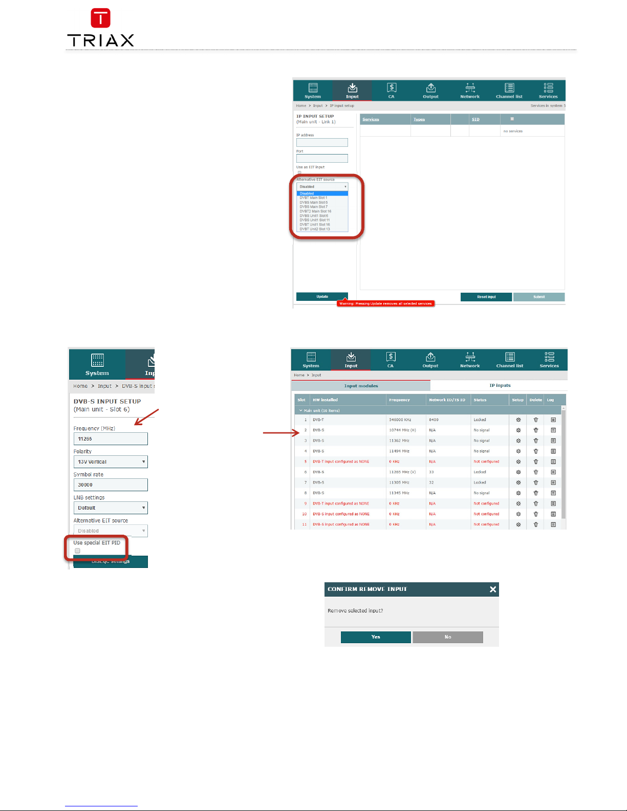
Specifying Alternative EIT/EPG source
Page 32
TDX Headend System Main Unit
Black Edition
EN
32
1. Specify the desired
IP address
and associated
IP
port number
in the corresponding fields.
2. Open the
Alternative EIT source
drop-down list.
3. Select the
EIT source
to be used.
4. Press the
Update
button.
5. Check the
Selected services
checkbox for one or
more services to select the service(s) you want to
use
6. View the
Status information
area to ensure that IP
data is being sourced through Link 1 or 2 on the
socket.
7. Press the
Submit
button.
EIT for Viasat services
It is possible to change the EIT at
PID 57 received at DVB-S input and
convert the EIT to the standard PID
(PID 18) for EIT. This function is for
Viasat services. To activate this
function select
Use special EIT PID
at the
Input
menu for DVB-S.
Modifying
To modify an existing IP input
configuration:
-Press the
Setup
button associated
with the IP input configuration.
-Make the required modifications
as when creating an IP input
configuration.
-Press the
Submit
button.
-Press the
Apply
button when the
modifications have been made.
Deleting
1. Press the
Delete
button of the IP input to
be removed.
2. Confirm that the selected IP input is to be
removed.
3. Press the
Apply
button.
IP output configurations
Page 33
TDX Headend System Main Unit
Black Edition
33
EN
Creating
The headend system offers the following possibilities
when you output IPTV services through the Link sockets.
IP multicast streaming (UDP streaming)
No RTP option
IGMP version 2
SPTS or MPTS including SDT, PAT, PMT, CAT
Packet ratio of 1 TS packet per IP packet
Not possible to change service ID (SID)
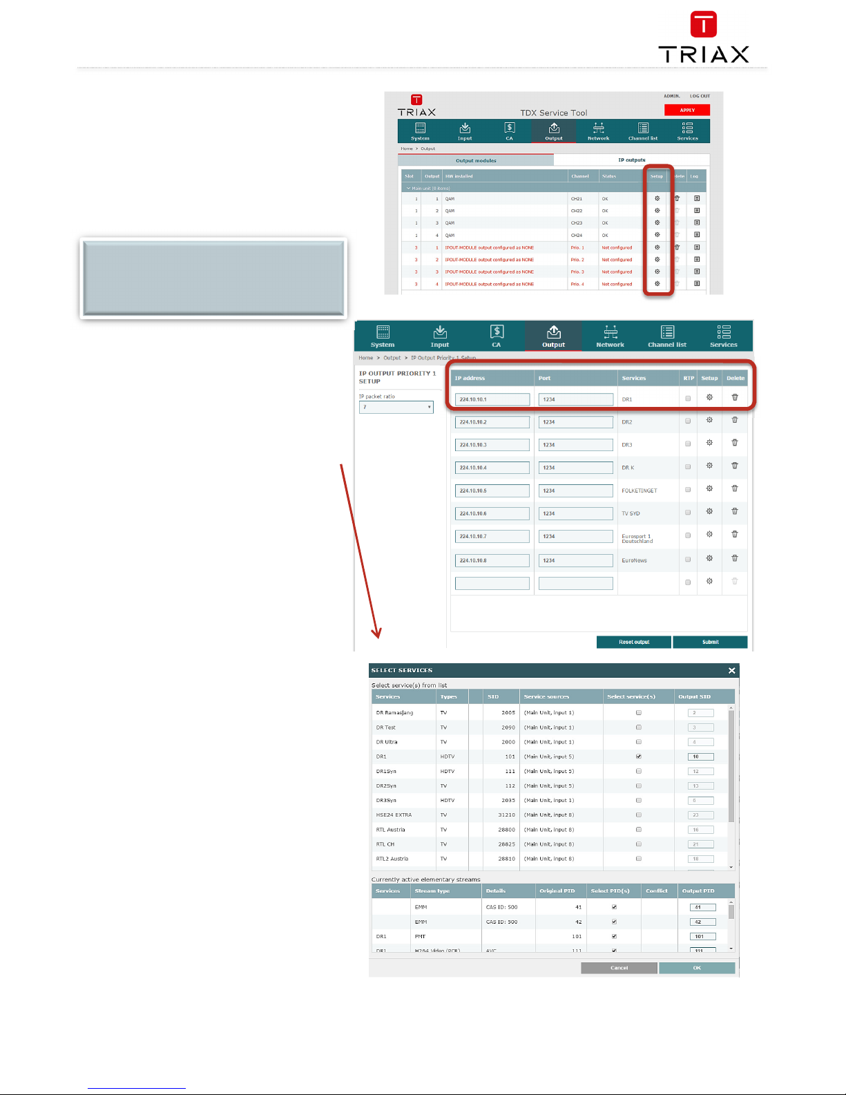
1. Select the
Output
tab.
2. Select the
IP outputs
sub-tab.
3. Press the
Setup
button for the link socket that
will process IP output.
4. Specify the desired
IP address
and associated
IP port number
in the corresponding fields.
5. Press the
Services
button.
The
Select Services
window displays services from input
that has entered the headend system through the same
unit which contains the Link socket(s) being used for
service distribution.
6. Select the services to be distributed through
the link.
7. Press the
UPDATE
button, down below.
Notes:
Services selected for one output on a Link will not be
selectable for other outputs on the same Link.
Re-scrambled and/or descrambled services cannot be
distributed using the Link sockets. They can, however, be
distributed using an IP output module and the AUX
sockets. The IP output module offers the possibility to
solve these limitations:
RTP
Set packet ratio for TS packets per IP packet
Changing service ID (SID)
Selection of descrambled service
Selection of scrambled service
See the IP output module user guide for further
information.
Creating - continued
NOTE:
Licenses for IP output are required to be able to use
the IPTV functionality in the headend. The licenses
can be purchased from Triax Sales, and need to be
activated, see “Activating licenses”.
Page 34
TDX Headend System Main Unit
Black Edition
EN
34
8. View the
Status information
area, down below, to see the
following:
The link’s RTP status
The transfer bitrate
The number of license services used.
The total number of purchased service licenses
9. Press the
Submit
button.
10. Press the
Apply
button
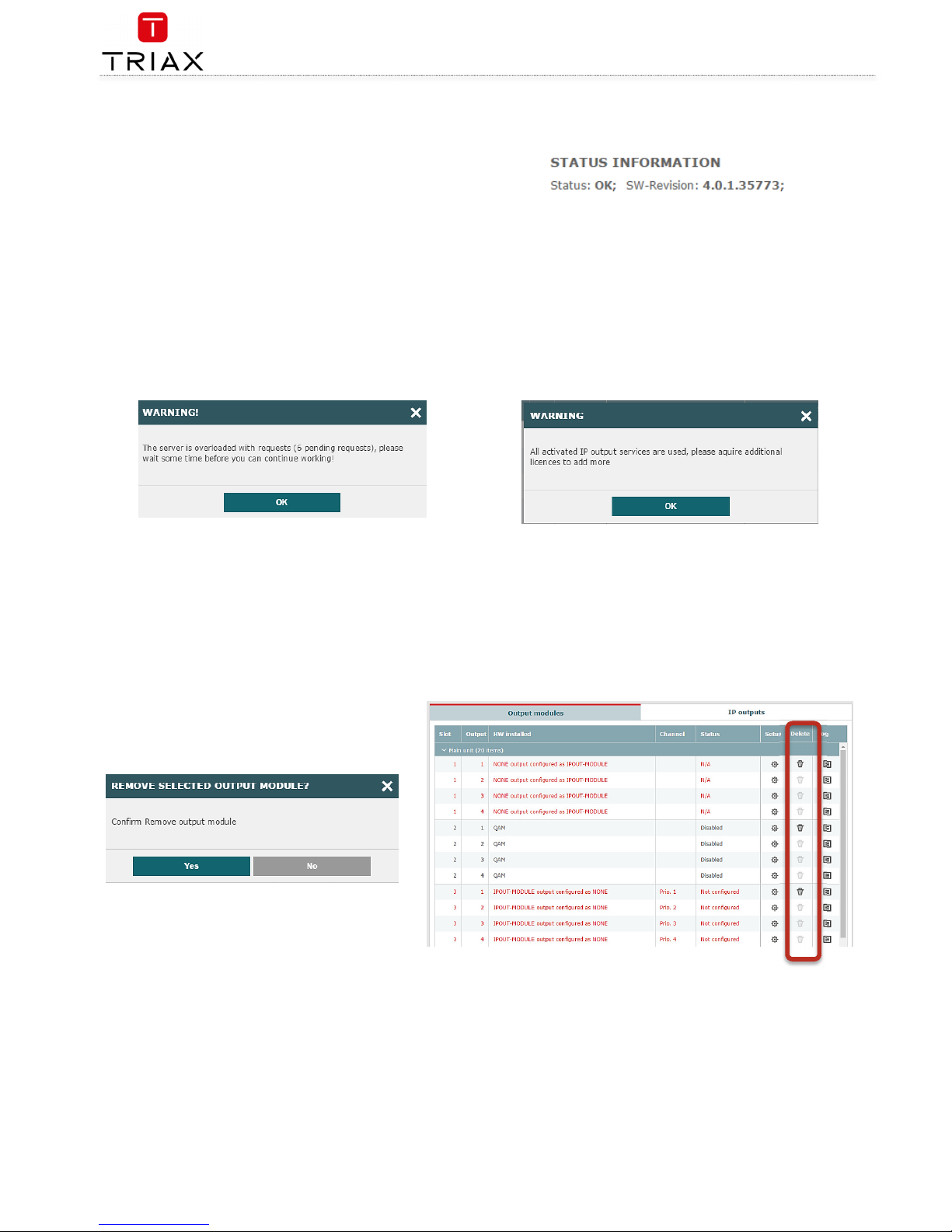
The following message is displayed if the server is busy fulfilling
requests from the user:
The following message is displayed if more services have been selected
than are permitted by the current licenses.
Modifying
To modify and existing IP output configurations:
1. Press the
Setup
button associated with the IP output configuration.
2. Make the required modifications as when creating an IP output configuration.
3. Press the
Submit
button on the IP output setup window.
Press the
Apply
button when the modifications have been made.
Deleting
1. Press the
Delete
button for the IP output to be
removed.
2. Confirm that the selected IP output is to be
removed.
3. Press the
Apply
button
EIT/EPG output
Page 35
TDX Headend System Main Unit
Black Edition
35
EN
If you want to distribute EIT information in connection with your IP output, you can choose between:
distributing EIT information with every single IP service, or
use a barker channel for carrying all EIT information for the IP output.
The EIT barker channel can be output in two ways depending on how you distribute your IP output:
IP output method
Barker channel distribution method
IP output is distributed through the Link
sockets.
EIT barker channel is output through Link 2 on the
main unit
IP output is distributed through an IP
output module.
EIT barker channel is output through the AUX
socket on the first IP output module in the
headend system
EIT –
every IP service
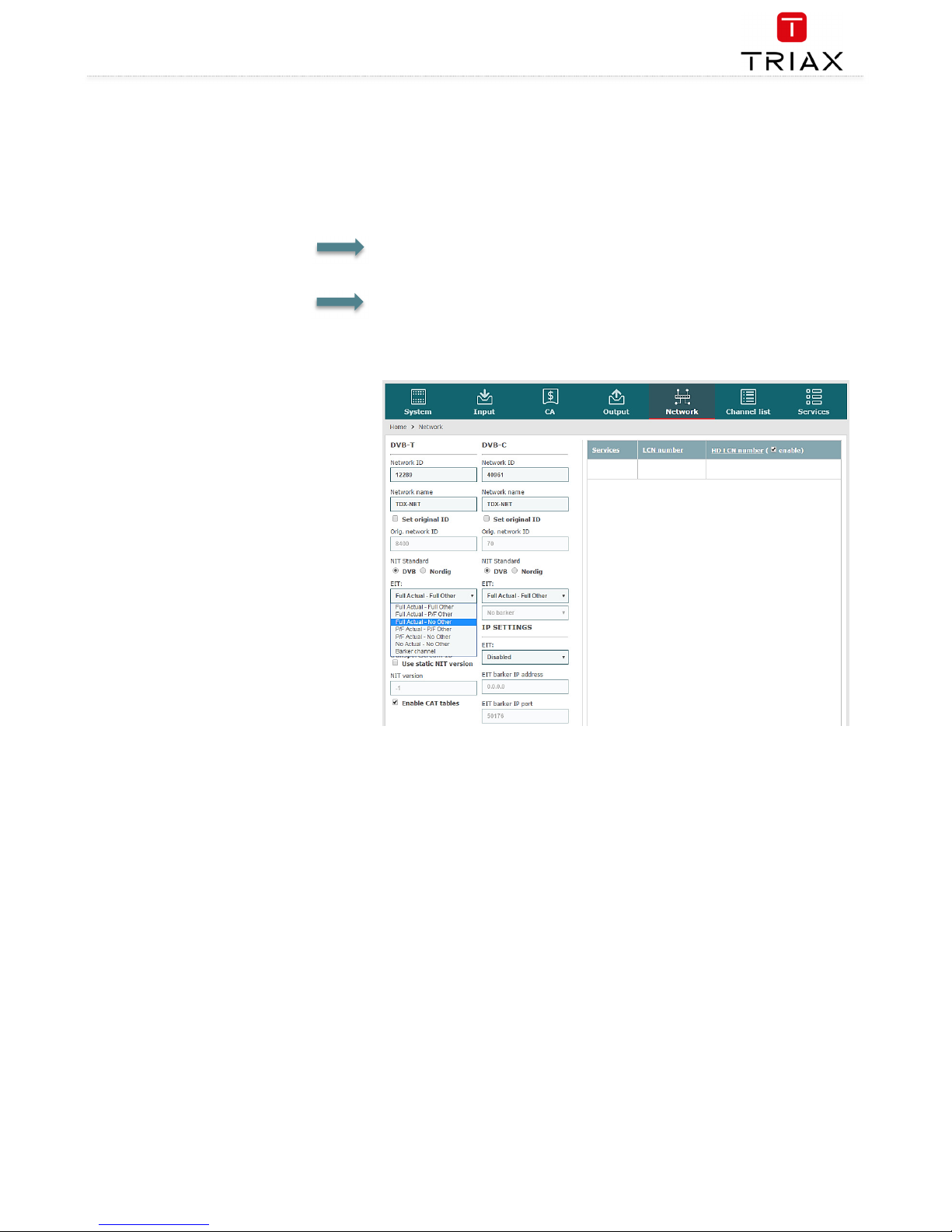
1. Select the
Network
tab in the Service Tool.
2. Open the
EIT
drop-down list.
3. Select “Full Actual – No other”.
4. Press the
Submit
button.
5. Press the
Apply
button.
EIT –
barker
channel
Page 36
TDX Headend System Main Unit
Black Edition
EN
36
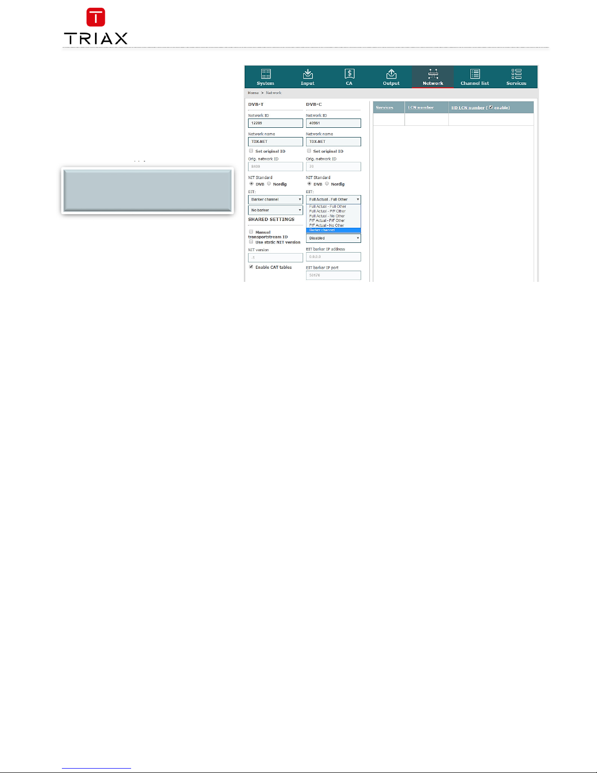
1. Select the
Network
tab in the Service
Tool.
2. Open the
EIT
drop-down list.
3. Select “Barker channel”.
4. Specify the IP address for the EIT barker
channel in the
EIT barker IP address
field.
5. Specify the associated port number in the
EIT barker IP port
field.
6. Press the
Submit
button.
7. Press the
Apply
button.
The
Network
window now contains a single line of
information stating which unit and socket is used by
the EIT barker channel.
PID handling
NOTE:
The IP address used for the barker channel
must not conflict with any of the IP addresses
used for service distribution.
Page 37
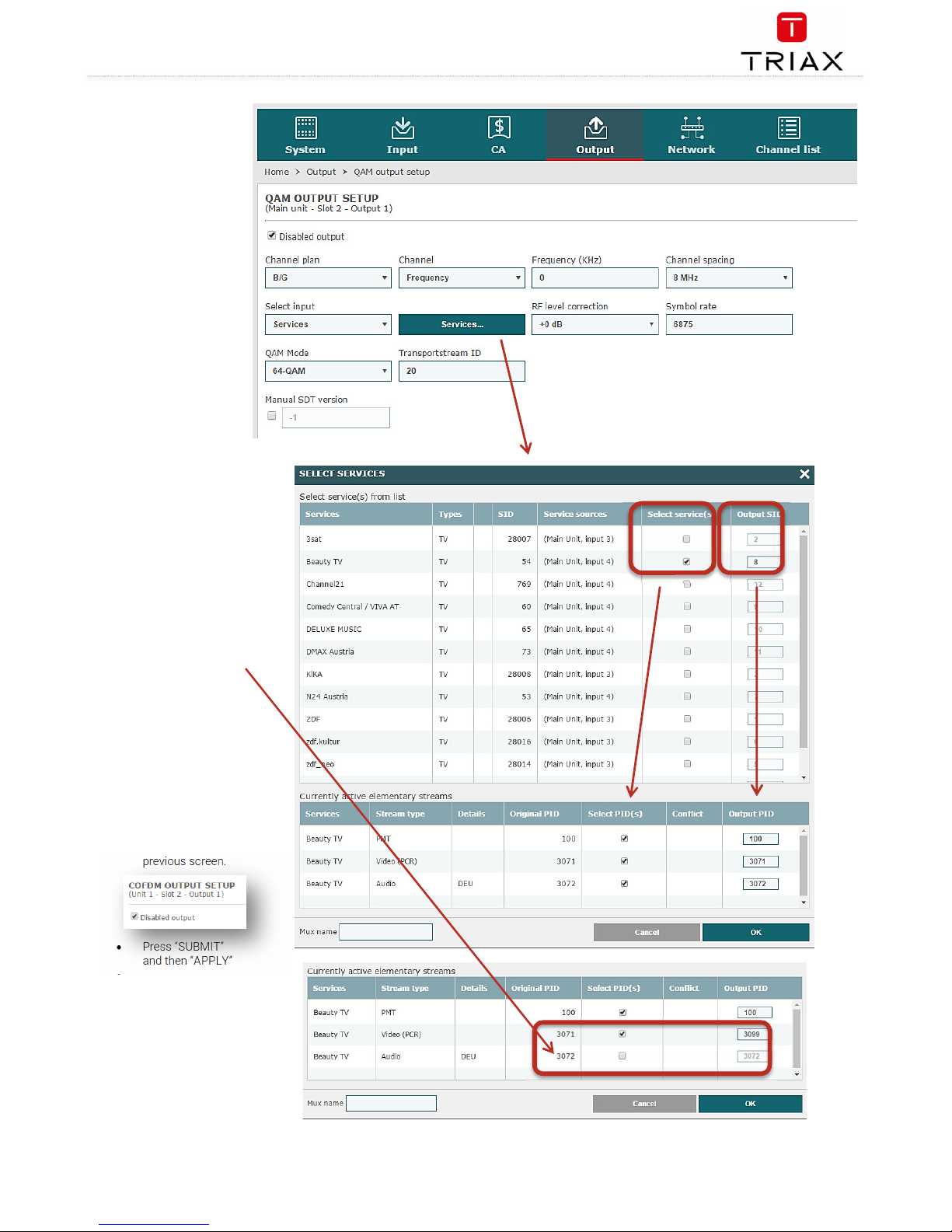
TDX Headend System Main Unit
Black Edition
37
EN
From S/W version 4.0.1 it is
possible to filter or even
remap the PID.
1. Find output and
press SERVICES
button.
2. A box opens – by
pressing the
SELECT SERVICES
you can
select/deselect
specific services.
3. It is also possible to
change the output
PID – remember
however that all
PID’s shall be
different.
Example:
Press button
SERVICES
At the shown QAM
output,
there is the
following services:
3SAT, KIKA, ZDF,
zdf-kultur, zdf-neo
and zdf-info.
Enable the “beauty
TV” service
Now you can see
the elementary
streams that
comes with the
service
You can choose to
hide
the audio by
uncheck the PID
(3072)
You can also
choose to remap
the Video PID from
3071 to 3099
Press OK
Remember to
uncheck
the field
“disabled output” at
the
previous screen.
Press “SUBMIT”
and then “APPLY”
This way it is
possible to have full
control over the
PID’s of
a specific stream
Page 38

TDX Headend System Main Unit
Black Edition
EN
38
SNMP traps
PowerUp
OID: 1.3.6.1.4.1.41359.1.1.1.1
Trap generated when the TDX will be power cycled.
Login
OID: 1.3.6.1.4.1.41359.1.1.1.2
Trap generated when the web configurator is logged on.
Logout
OID: 1.3.6.1.4.1.41359.1.1.1.3
Trap generated when the web configurator is logged out.
TimeOut
OID: 1.3.6.1.4.1.41359.1.1.1.4
Trap generated when the web configurator is timed out.
FailedLogin
OID: 1.3.6.1.4.1.41359.1.1.1.5
Trap generated when the web configurator login has failed.
Restart
OID: 1.3.6.1.4.1.41359.1.1.1.6
Trap generated when TDX is restarted.
InputError
OID: 1.3.6.1.4.1.41359.1.1.1.7
Trap generated when an input module has an error, e.g. module no longer locked to frequency, missing
module etc,
CIInsertion
OID: 1.3.6.1.4.1.41359.1.1.1.8
Trap generated when a CI module is inserted in the TDX.
CIRemoval
OID 1.3.6.1.4.1.41359.1.1.1.9
Trap generated when a CI module is removed from the TDX.
ModuleInsertion
OID 1.3.6.1.4.1.41359.1.1.1.10
Trap generated when an input or output module is inserted.
ModuleRemoval
OID 1.3.6.1.4.1.41359.1.1.1.11
Trap generated when an input or output module is removed.
CIDescramblingError
OID 1.3.6.1.4.1.41359.1.1.1.12
Trap generated when a service descrambling has an error.
CICommunicationDown
OID 1.3.6.1.4.1.41359.1.1.1.13
Trap generated when communication with CI module fails.
VideoDecodingError
OID 1.3.6.1.4.1.41359.1.1.1.14
Trap generated when video decoding of a service in a PAL output module fails.
InterlinkDisconnect
OID 1.3.6.1.4.1.41359.1.1.1.15
Trap generated when main unit loses connection to a subunit.
ConfigurationChangeApplied
OID 1.3.6.1.4.1.41359.1.1.1.16
Trap generated when the user applies changes in the web configurator.
InputOK
OID 1.3.6.1.4.1.41359.1.1.1.17
Trap generated when an input module error disappears, e.g. errors that can disappear are input module
no longer locked to frequency, missing module etc,
CIDescramblingOK
OID 1.3.6.1.4.1.41359.1.1.1.18
Trap generated when a service descrambling error disappears.
CICommunicationUP
OID 1.3.6.1.4.1.41359.1.1.1.19
Trap generated when communication with the CI module no longer fails.
VideoDecodingOK
OID 1.3.6.1.4.1.41359.1.1.1.20
Trap generated when a video decoding of a service in PAL output module no longer fails.
InterlinkConnect
OID 1.3.6.1.4.1.41359.1.1.1.21
Trap generated when a main unit is connected to a subunit
Manufacturer
Dear Customer
Should you require technical assistance in the event that your expert dealer is unable to help you, please contact us at:
Triax A/S
Bjørnkærvej 3
8783 Hornsyld
Denmark
Tel.: +45 76 82 22 00
mail: [email protected]
web: www.triax.dk
Page 39

TDX Headend System Main Unit
Black Edition
39
EN
This page is intentionally left blank !
Diese Seite ist mit Absicht leer !
Cette page a été laissée blanche intentionnellement !
Esta página se ha dejado en blanco intencionalmente !
Denne side er med vilje efterladt tom
Page 40

triax.com/support
For further information
and updated manuals go to
Copyright © 2016 TRIAX. All rights reserve d. The TRIAX Logo and TRIAX, TRIAX Multimedia are registered
trademarks or trademarks of the TRIAX Company or its affiliate s.
All specifications in this guide are subjec t to change without further notice.
TRIAX A /S | Bjø rnkærv ej 3 | DK-8783 Hornsyld | Denmark
 Loading...