

Page 1
User Manual
Modulator MOD 102T
Article Article no.
MOD 102T
Version A Date 02/2018 EN
Modulator
300127
Page 2

Introduction
The MOD102T modulator has an HDMI input with local loop through, and a COFDM
output which is combined with the RF input. The HDMI input content can be supplied by
a number of sources, Blu-ray player, Satellite Set top box, CCTV etc. The input signal is
modulated as a COFDM output and can be distributed to a number of TV’s over an
existing private coaxial network.
It has an HDMI loop through, to connect to the local TV, and can also combine existing
RF with the modulated output channel on RF Out 1 and RF Out 2. The modulator has
adjustable level control to balance the COFDM channel with the incoming RF channels.
The source Set top box can be controlled from another TV location, via the IR remote
control over the coaxial cable, using an IR transmitter and a digital link. The coaxial
network must be connected to the RF Out 2, with the 9vdc able to pass through the
network, to remotely power the digital link.
The MOD102T Modulator can be set up, either via the front panel and LCD screen, or
through the Web user interface (RJ45 connector). Please see below for full instructions.
Page 3
Equipment Detail
MOD102T Basic Installation:
1. Connect
2. Connect
3. Connect
4. Connect
5. Plug power adapter into
Connect MOD102T with IR Transmitter and Triax Digital Link:
1. Connect the IR Transmitter to
the receiver (STB)
2. Connect Triax Digital Link (not included in accessories) at the other TV location, ensure the coax
network is connected to
For WebUI adjustment and Upgrade
HDMI In (4)
HDMI Output (3)
RF Out 1 (B)
RF In (1)
and Receiver (STB)
and local TV
and local TV
with Terrestrial input (Aerial)
DC9V/2A (8)
IR sensor (2)
RF Out 2 DC9V (C)
at the rear of the Modulator and ensure it points to
.
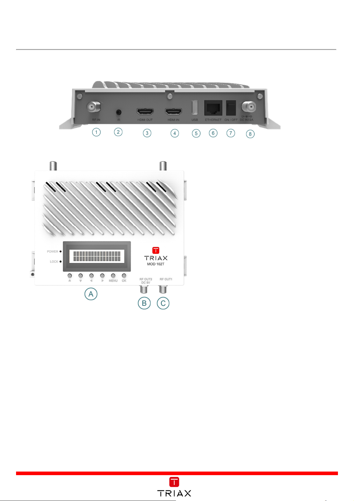
Interface
:
1. RF In
2. IR Sensor
3. HDMI Out
4. HDMI In
5. USB
6. Ethernet
7. On/Off
8. DC 9V/2A
A. Buttons: ▲▼◄ ► Menu, OK
B. RF Out 1
C. RF Out 2 DC 9V
1. Connect
Ethernet (6)
and PC/Laptop via RJ45 to adjust setting and apply software upgrades.
Page 4
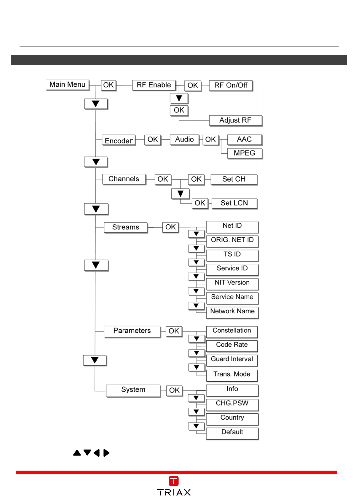
SET UP
Instruction o
n how to
set up the modulator using the front panel LCD display
Press OK and to make any adjustments or changes, confirm changes by pressing OK again.
Page 5
Instruction of how to use
WebUI
1.
Connecting to modulator
Step 1: Set the PC’s static IP address to 169.254.0.100
Step 2: Connect MOD102T to computer via an Ethernet cable.
Step 3: Open your browser and enter 169.254.0.3
(The Web UI only supports Windows 7 browsers or above.)
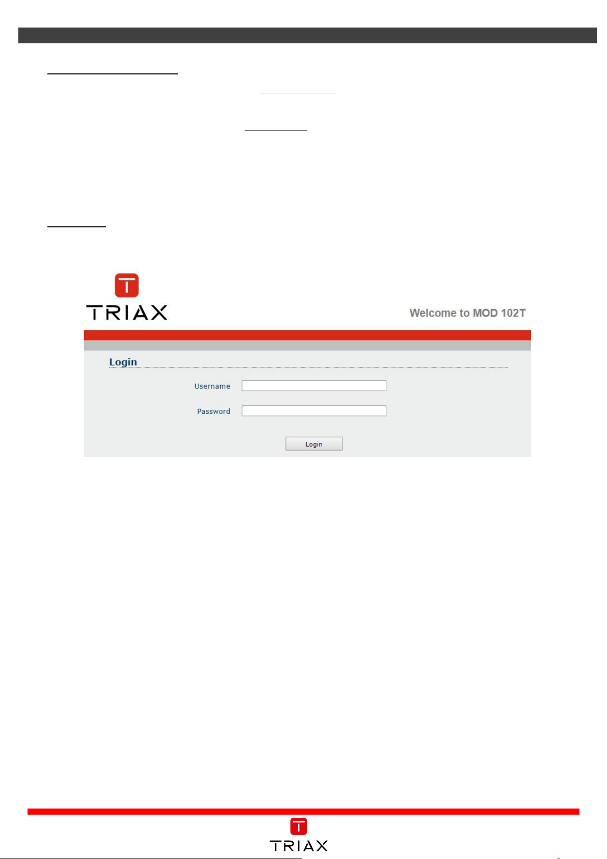
2.
Login Page:
Enter user name and password, and click login button.
Username: user
Password: 12345
<<After login, you can see main page as below>>
Page 6
3.
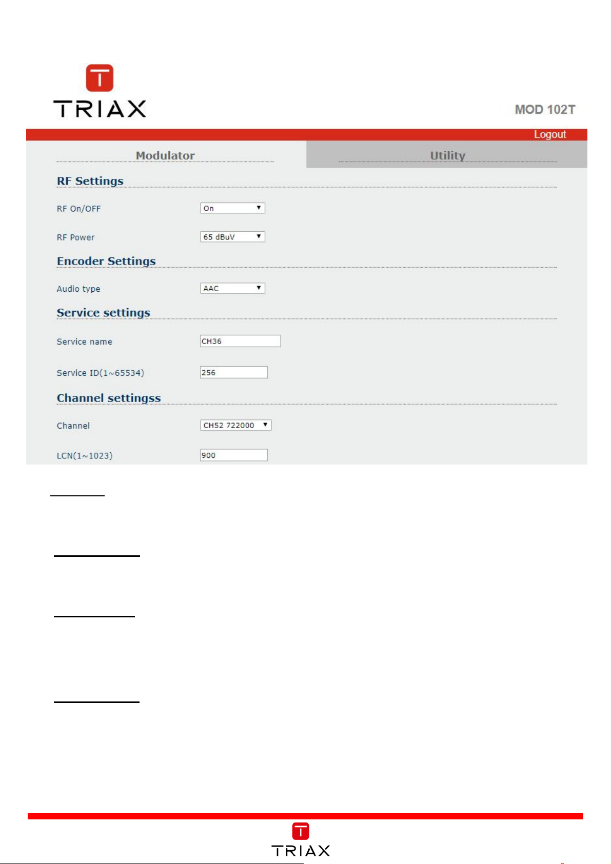
Modulator Setting:
RF Status:
1. RF On/Off: Users can either turn the RF on or off in this this menu.
Encoder Setting:
1. Audio Type: Users can choose either AAC or MPEG.
Service Setting:
1.
Service Name: Users can edit the service name (TV Program Name).
2.
Service ID: Users are able to define a device ID from 1 to 65534.
Channel Setting:
1.
Channel: Users can select the RF output channel number from the pre-set UK channel plan.
2.
LCN: Users can define the Logical Channel Number from 1 to 1023.
Page 7
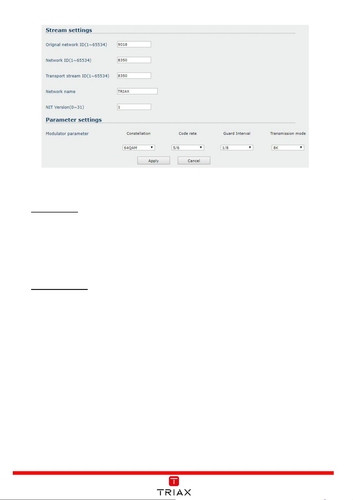
Stream Setting:
1.
OrgNetwork ID: Users Users can edit OrgNetwork ID from 1 to 65534.
2.
Network ID: Users can edit Network ID from 1 to 65534.
3.
TS ID: Users can edit TS ID from 1 to 65534.
4.
Network Name: Users can define the Network name.
Parameter Setting:
1.
Constellation: The MOD102T contains the following constellation modes: QPSK, 16QAM and
64QAM.
2.
Code Rate: Refers to the FEC (Forward Error Correction) rate. Which can be set as 5/6, or 7/8
3.
Guard Interval: Users can select either 1/8, 1/16, 1/32.
4.
Transmission Mode: Transmission mode can be set as either 2K and 8K FFT
Page 8
4.
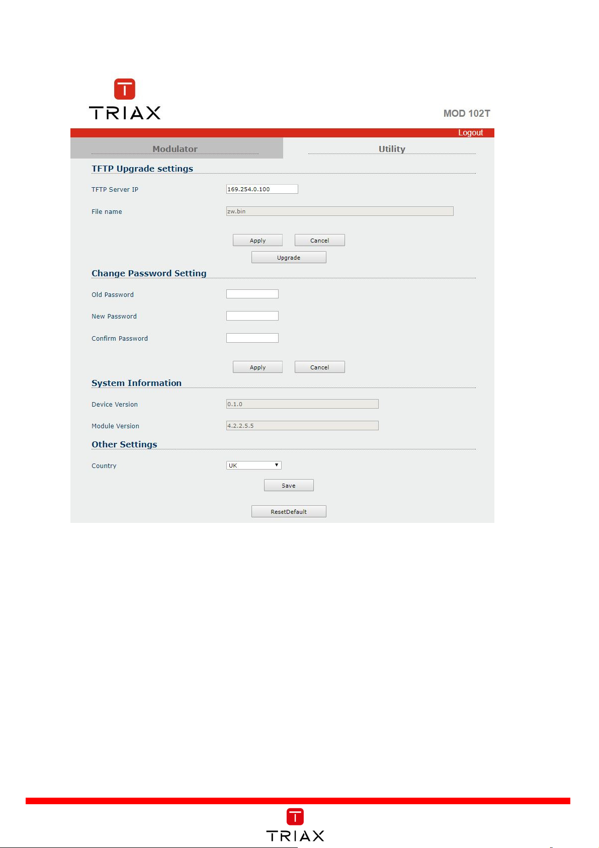
Utility:
Tftp Upgrade:
Select and upload bin file & apply firmware upgrade (details below).
Change Password Setting:
Old Password: Enter old password.
New Password: Enter pew password.
Confirm Password: Enter new password again.
System Information:
This shows the Device Version and Module Version.
Other Settings:
The user can also change the language setting to English, French, German, or Danish.
Page 9

Tftp Upgrade instruction
5.
Tftp Upgrade instruction
Set the PC’s static IP address to 169.254.0.100
I.
Launch Tftp tool and enter the below information under DHCP server tab.
II.
User can assign any
location, but the update file
must be in the assigned
folder.
Open the internet browser and enter: 169.254.0.3
III.
Username: user
Password: 12345
Page 10

IV.
Select Utility tab and click Tftp Upgrade button
The web page and Tftp will begin the upgrade process.
V.
Page 11

6.
Modulator default settings and options
Modulator Setting Description Default value Option
RF Settings
Encoder Settings
Service Settings
Channel Settings
Stream Settings
RF On/off On On/Off
Output power 65 85,78,72,65
Audio Type AAC AAC/MPEG
Service name CH 62 Edit Service Name
Service ID
256 Enter value : 1~65534
(1~65534)
Channel CH36 CH 21 ~ 69
LCN (1~1023) 900 Enter value : 1~1023
Orgnetwork ID
9018 Enter value : 1~65534
(1~65534)
Parameter Settings
Network ID
8350 Enter value : 1~65534
(1~65534)
TS ID (1~65534) 8350 Enter value : 1~65534
Network Name TRIAX Edit Network Name
Constellation 64QAM QPSK/16QAM/64QAM
Code Rate 5/6 5/6, 7/8
Guard Interval 1/8 1/8,1/16,1/32
Transmission
8K 2K, 8K
Mode
Bandwidth
8
7/8
Page 12

8
9
Default Settings
Country
RF Output
Encoder Audio type
Factory Setting
UK
RF Enable
RF Power (dBuV)
France
On
65 65 65 65 65
AAC
On
AAC
Denmark
On
AAC
Germany
On
AAC
Italy
On
AAC
Channels
Parameter
Service
Stream
Service Name
Service ID
Set CH
Set LCN
Private Data Specifier
Descriptor
ON ID
N ID
TS ID
Network Name
NIT Version
Constellation
Trans. Mode
Guard Interval
Code Rate
CH62
CH21
CH62
CH62
CH62
256 256 256 256 256
CH36
CH21
CH62
CH62
CH62
900 39 62 No loop No loop
0x0000233A
0x0000002
0x0000002
No loop
No loop
9018 8442 8400 8468 8572
8350 8442 12801 12289 12289
8350 301 8350 8350 8350
TRIAX
64QAM
1
30
64QAM
8K
1/8
5/6
TRIAX
8K
1/8
5/6
TRIAX
1
64QAM
8K
1/8
5/6
TRIAX
1
64QAM
8K
1/8
5/6
TRIAX
1
64QAM
8K
1/8
5/6
System
Info
Default
Password Old, New, Confirm
12345 12345 12345 12345 12345
Other
Language
English
Copyright © 2018 TRIAX. All rights reserved.
The TRIAX Logo and TRIAX, TRIAX Multimedia are registered trademarks or
trademarks
of the TRIAX Company or its affiliates.
All specifications in this guide are subject to change without further notice.
French
Danish German
 Loading...