

Page 1
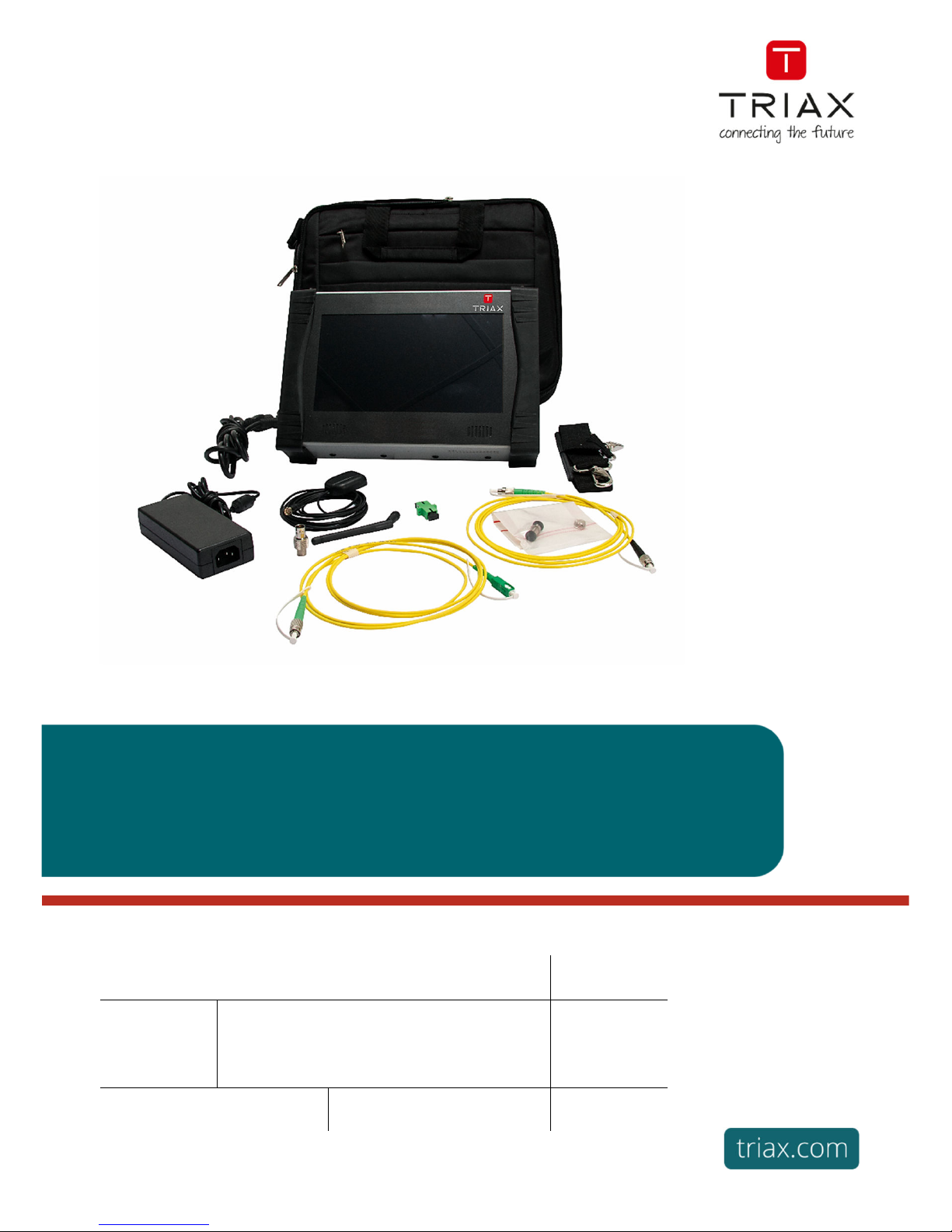
User Manual
TRIAX measuring instruments
MCT 08x series
Article Article no.
MCT 080
MCT 081
MCT 082
MCT 085
TRIAX Measuring instruments MCT 08x series
812980
812981
812982
812985
Version A Date 09/2018 EN
Page 2

– MCT08x –
GUARANTEE
Your instrument is guaranteed for two years for labour and parts against any manufacturing defect and/or functioning hazard.
This guarantee extends from the delivery date and ends 730 calendar days later.
In case of guarantee contract, this will cancel or replace these guarantee conditions hereabove.
The guarantee conditions by TRIAX are available on the website www.triax.com. The general guarantee conditions should
prevail on the following conditions that they sum up.
This guarantee does not cover the result of any abnormal use, handling mistake or mistake in the storage conditions outside the
defined range.
In case of application of the guarantee, the user shall return, at its own expenses, the relevant appliance to our office in the
country you’ve purchased this meter:
And add a description of the observed breakdown to the appliance.
The standard supplies provided with the appliance (cables, outlets…), the consumables (batteries …) and the optional supplies
(suitcases…) are guaranteed for 3 months against any manufacturing defect.
Such items as a suitcase, a LCD screen or a touchpad are guaranteed only for a normal use.
The guarantee does not cover wearing, accidental breaks or consecutive to a shock or any abnormal use.
The factory options integrated to the appliance are guaranteed for the same duration as the appliance itself.
In case of replacement or repair of the product, the remaining guarantee duration shall be:
- The remaining duration of the guarantee if the appliance is still under guarantee
- If the guarantee duration is less than 90 days, the replaced part is guaranteed for 90 days
Any replacement part becomes the property of the user and the exchanged parts become the property of TRIAX.
In case of intervention by an insurance company, the product becomes the property of the insurance company upon its
exclusive request. Else, it shall remain property of the user.
The guarantee covers exclusively the materials manufactured and provided by TRIAX.
Any intervention by the user or any third party without prior authorization by the company voids the guarantee.
The user shall be responsible for the return of its appliance to our site. Hence, it shall provide for a conditioning that shall
correctly protect the appliance while shipping. It shall subscribe, at its own expenses, any insurance required for the transport.
The TRIAX company reserves the right to refuse any product wrongly conditioned and not to take in charge any break
consecutive to the transport.
Particular case of the battery: There is a Li-ion battery as a standard equipment of this appliance. It shall not be transported
outside the appliance. In no case shall the user replace it. Its replacement in the factory is necessary to check the charge system
and the protective securities.
What to do in case of malfunction?
In case of malfunction or for any advice for use, please contact the technical support by TRIAX.
A technician shall answer you and give you any information required to solve your problem.
What to do in case of failure?
In case of failure of your appliance, please contact the after-sales support.
Please contact our Technical Support: http://www.triax.com/support
We thank you for your trust.
Page 3

FIELD METERS MCT 080 / 081 / 082 / 085 USER MANUAL
p. 2
METROLOGY
The meteorological conditions of your measurement instrument are defined in the specifications of this notice. Climate and
environmental conditions restrict the specifications of your Field Strength Measurer (MDC). TRIAX checks the characteristics
of each appliance one by one on an automatic bench during its manufacture. The adjustment and control are guaranteed under
conditions of the ISO9001 certification by facilities in connection with the COFRAC (or equivalent in the context of ILAC
reciprocity).
The specified characteristics are considered stable for a period of 12 months from the first use under normal conditions of use.
We recommend a check after 12 months and max. 24 months of use, then every 12 months after 24 months.
For any check of the characteristics, the following average climate conditions shall be maintained (23°C+3°C – 50(+20)%RH).
The MDC should have been working for 0,5 hour before check.
We recommend that you have this control made by our after-sales service (Service Après-Vente) for the best service and
preservation of the measuring quality of your instrument.
When a MDC returns to TRIAX, maximum service is provided with internal updating according to the required adjustments
and software updates. In case of shift in the characteristics, your instrument shall be adjusted to recover its original
characteristics.
PACKAGING
The packaging of this product is fully recyclable. Its design allows the transport of your instrument under the best
possible conditions. Please note that the original packaging should be additionally wrapped in case of transport by air,
road or postal
Page 4

FIELD METERS MCT 080 / 081 / 082 / 085 USER MANUAL
p. 3
TABLE OF CONTENTS
1 Important information .......................................................................................................... 7
1.1 Particular precautions .............................................................................................................................. 7
1.2 Security instructions ................................................................................................................................. 7
1.3 Conformity and restrictions of the appliance ............................................................................................. 7
2 Quick start-up ....................................................................................................................... 8
2.1 Presentation of the appliance ................................................................................................................... 8
2.2 Signal spotting ....................................................................................................................................... 10
2.2.1 Checking a terrestrial antenna .......................................................................................................... 10
2.2.2 Installation of a terrestrial antenna .................................................................................................... 11
2.2.2.1 Using Spectrum function .......................................................................................................... 11
2.2.2.1 Using Pointing function............................................................................................................. 13
2.2.3 Installation of a satellite dish............................................................................................................. 14
2.2.3.1 Using Spectrum function .......................................................................................................... 14
2.2.3.2 Using Pointing function............................................................................................................. 16
3 Presentation ....................................................................................................................... 19
3.1 General.................................................................................................................................................. 19
3.2 Description of the appliance ................................................................................................................... 20
4 Power-up ............................................................................................................................. 22
4.1 Battery ................................................................................................................................................... 22
4.2 Charging battery .................................................................................................................................... 22
4.3 External power supply ............................................................................................................................ 23
4.4 Turning the appliance on and off ............................................................................................................ 23
5 Man-machine interface ...................................................................................................... 24
5.1 Content of the screen ............................................................................................................................. 24
5.2 Changing a name or a value .................................................................................................................. 26
5.2.1 Change inside a table ...................................................................................................................... 26
5.2.2 Change with selection ...................................................................................................................... 27
5.2.3 Change with virtual keyboard ........................................................................................................... 27
5.3 Lists of measurements and setup library ................................................................................................ 28
6 Measurement lists .............................................................................................................. 31
6.1 The List page ......................................................................................................................................... 31
6.2 Modification of a list ............................................................................................................................... 32
7 Setup library ....................................................................................................................... 34
7.1 The Library page .................................................................................................................................... 34
7.2 Creation or modification of setups in the library ...................................................................................... 34
8 AUTOSET mode ................................................................................................................. 37
8.1 Terrestrial mode ..................................................................................................................................... 38
8.2 Satellite mode ........................................................................................................................................ 38
8.3 Cable mode ........................................................................................................................................... 39
8.4 «START » .............................................................................................................................................. 39
Page 5

FIELD METERS MCT 080 / 081 / 082 / 085 USER MANUAL
p. 4
9 Pointing antennas .............................................................................................................. 41
9.1 Terrestrial antenna pointing .................................................................................................................... 42
9.1.1 Updating channels ........................................................................................................................... 43
9.2 Satellite dish pointing ............................................................................................................................. 45
9.2.1 Updating satellites ............................................................................................................................ 47
9.2.2 Double Check Sat ............................................................................................................................ 48
9.2.3 Alignment of the satellite dish ........................................................................................................... 48
9.2.4 Azimut-Elevation-Polarization ........................................................................................................... 49
10 The Measures-TV-Spectrum page .................................................................................... 50
10.1 Modification of parameters.................................................................................................................. 51
10.2 « AutoLock » function ......................................................................................................................... 51
10.3 Level measurements .......................................................................................................................... 52
10.3.1 Satellite band ................................................................................................................................... 52
10.3.2 Terrestrial band ................................................................................................................................ 53
10.4 C/N .................................................................................................................................................... 54
10.5 Thresholds ......................................................................................................................................... 55
10.6 Digital measurements ......................................................................................................................... 55
10.7 DVB-T/H............................................................................................................................................. 57
10.8 DVB-T2 / T2 Lite ................................................................................................................................. 58
10.9 DVB-C ................................................................................................................................................ 59
10.10 J83B (MCNS) ..................................................................................................................................... 60
10.11 DVB-C2 .............................................................................................................................................. 61
10.12 DVB-S and DSS ................................................................................................................................. 62
10.13 DVB-S2 .............................................................................................................................................. 63
10.13.1 Multistream ...................................................................................................................................... 63
10.14 FM-RDS ............................................................................................................................................. 65
10.15 DAB/DAB+ ......................................................................................................................................... 66
11 Spectrum analyser ............................................................................................................. 67
11.1 Display modes .................................................................................................................................... 68
11.2 NIT/TV ............................................................................................................................................... 70
12 Image and Sound ............................................................................................................... 72
12.1 Digital TV ........................................................................................................................................... 72
12.2 Audio.................................................................................................................................................. 73
12.3 Table of services ................................................................................................................................ 73
12.4 PID function........................................................................................................................................ 73
12.5 NIT function ........................................................................................................................................ 74
12.6 Record function PVR .......................................................................................................................... 74
12.7 ETR290 Alarms function ..................................................................................................................... 75
12.8 ETR290 Bitrates function .................................................................................................................... 76
12.9 CAM installation / Access card............................................................................................................ 77
13 Monitoring........................................................................................................................... 78
14 Remote power supply / LNB – DiSEqC ............................................................................ 79
14.1 Terrestrial band .................................................................................................................................. 79
14.2 Satellite band ..................................................................................................................................... 80
Page 6

FIELD METERS MCT 080 / 081 / 082 / 085 USER MANUAL
p. 5
14.2.1 Launching ........................................................................................................................................ 80
14.2.2 Switches .......................................................................................................................................... 81
14.2.3 Positioner......................................................................................................................................... 82
14.2.4 DCSS .............................................................................................................................................. 83
14.2.4.1 Influence of the DCSS on the spectrum analyzer ...................................................................... 85
15 Measurement map .............................................................................................................. 86
15.1 Measurements filtering ....................................................................................................................... 86
15.2 Periodic scan ...................................................................................................................................... 86
15.3 USB recording .................................................................................................................................... 87
15.4 Values beyond tolerance .................................................................................................................... 88
15.5 Graphics............................................................................................................................................. 88
16 Constellation ...................................................................................................................... 90
17 Echo / Guard interval ......................................................................................................... 91
18 MER/Carrier ........................................................................................................................ 94
19 Shoulder Attenuation ......................................................................................................... 95
20 SFN Delay ........................................................................................................................... 96
21 ASI function ........................................................................................................................ 97
22 A/V function (external video)............................................................................................. 98
23 GPS ..................................................................................................................................... 99
23.1 VIEW function .................................................................................................................................... 99
23.2 LOG function .................................................................................................................................... 100
23.3 MAPPING function ........................................................................................................................... 100
23.3.1 Recording a file .............................................................................................................................. 102
23.3.2 Export and cartography .................................................................................................................. 103
24 Optical Fiber function ...................................................................................................... 105
24.1 What you should know...................................................................................................................... 105
24.1.1 Optical fiber ................................................................................................................................... 105
24.1.2 Connectors .................................................................................................................................... 106
24.2 Satellite reception ............................................................................................................................. 107
24.3 Wavelengths .................................................................................................................................... 108
24.4 Optical Power measurement ............................................................................................................. 109
25 5GHz input ........................................................................................................................ 110
26 WIFI ................................................................................................................................... 112
27 IPTV function .................................................................................................................... 113
27.1 Mesures IPTV .................................................................................................................................. 113
27.2 Inter-Arrival-Time IPTV ..................................................................................................................... 117
27.3 TV IPTV ........................................................................................................................................... 118
28 Save ................................................................................................................................... 119
29 Configuration.................................................................................................................... 120
29.1 Language ......................................................................................................................................... 120
29.2 Frequency map ................................................................................................................................ 120
Page 7

FIELD METERS MCT 080 / 081 / 082 / 085 USER MANUAL
p. 6
29.3 Memories ......................................................................................................................................... 120
29.3.1 View .............................................................................................................................................. 121
29.3.2 Save .............................................................................................................................................. 121
29.3.3 Save all .......................................................................................................................................... 122
29.4 Adjustment ....................................................................................................................................... 123
29.4.1 Measurement unit .......................................................................................................................... 123
29.4.2 Impedance ..................................................................................................................................... 123
29.4.3 Bip ................................................................................................................................................. 123
29.4.4 LCD ............................................................................................................................................... 123
29.4.5 IP address ..................................................................................................................................... 123
29.4.6 Password ....................................................................................................................................... 124
29.4.7 Background ................................................................................................................................... 124
29.5 Configuration .................................................................................................................................... 125
29.6 Update ............................................................................................................................................. 126
29.7 Factory recovery ............................................................................................................................... 126
30 Software update ............................................................................................................... 127
31 Connection of the appliance to a PC .............................................................................. 128
31.1 Required configuration...................................................................................................................... 128
31.2 ETHERNET interface ....................................................................................................................... 128
31.3 Network connexion ........................................................................................................................... 129
32 HDMI Connection ............................................................................................................. 130
33 Displayed messages ........................................................................................................ 131
33.1 Alert messages................................................................................................................................. 131
33.2 Error messages ................................................................................................................................ 132
34 Maintenance ..................................................................................................................... 133
35 Technical specifications .................................................................................................. 135
35.1 Selection Guide ................................................................................................................................ 135
35.2 Common technical specifications ...................................................................................................... 136
35.3 Digital measurements ....................................................................................................................... 137
35.4 Divers ............................................................................................................................................... 139
35.5 General specifications ...................................................................................................................... 140
35.6 Accessories ...................................................................................................................................... 140
35.7 V, dBµV, dBmV et dBm conversion................................................................................................... 141
35.8 Typical values for measurements...................................................................................................... 141
Page 8
FIELD METERS MCT 080 / 081 / 082 / 085 USER MANUAL
p. 7
1 Important information
Please read carefully the following instructions before using your appliance.
1.1 Particular precautions
Do not use the product for any other use than specified.
Use the provided charger unit to prevent any deterioration of the appliance and guarantee its measurement
characteristics.
Do not use in a wet environment.
Do not use in an explosive environment.
In case of failure or for the maintenance of the appliance, only a qualified personal shall be entitled to work on
it. In such a case, it is required to use TRIAX spare parts.
Do not open the appliance: risk of electric shock.
You should use the F/F adaptor provided with your measuring instrument. Any other adaptor could damage
your appliance and jeopardizes the guarantee.
Do not use gloves, stylus or any other object on to the touchscreen. Handle the screen carefully.
1.2 Security instructions
For a correct use of the appliance, it is necessary that users abide by the security and use instructions
described in this manual.
Symbols on the appliance:
Attention: Refer to the manual. Shows a risk of damage for the material connected to the
instrument or to the instrument itself.
Ground: Grounded accessible parts.
Product for recycling.
1.3 Conformity and restrictions of the appliance
See chapter EC Declaration of conformity.
Page 9
FIELD METERS MCT 080 / 081 / 082 / 085 USER MANUAL
p. 8
2 Quick start-up
2.1 Presentation of the appliance
Important keys:
MCT08x is an appliance with a capacitive touchscreen. This requires a soft handling. No glove and no stylus
should be used, so that the triggering should be taken into account.
You will recognize the « keys » by their dark grey color.
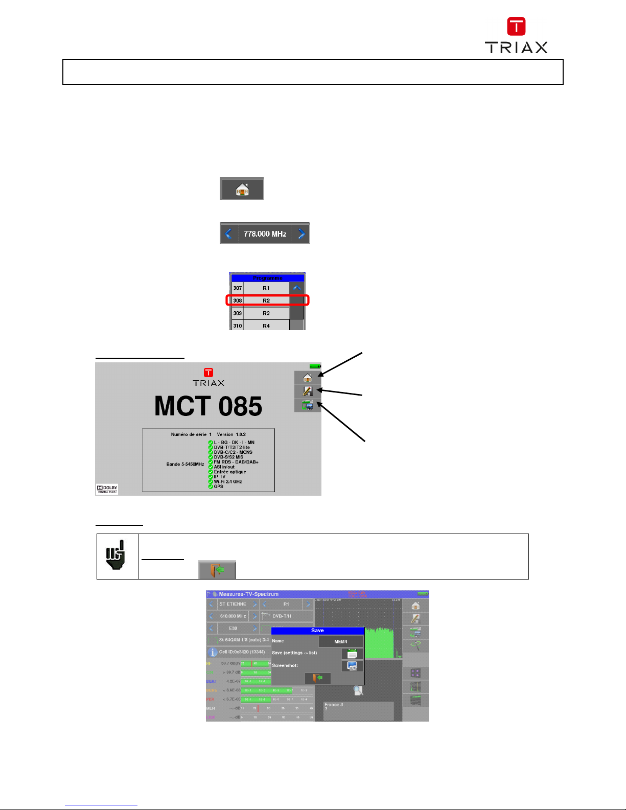
Example the HOME key :
Some parameters can move ‘step by step’ : use arrows on each side of the value.
Frequency example :
You may also access tables by pressing lines (on white or yellow)
Attention: To exit a window like in this example below, press the key:
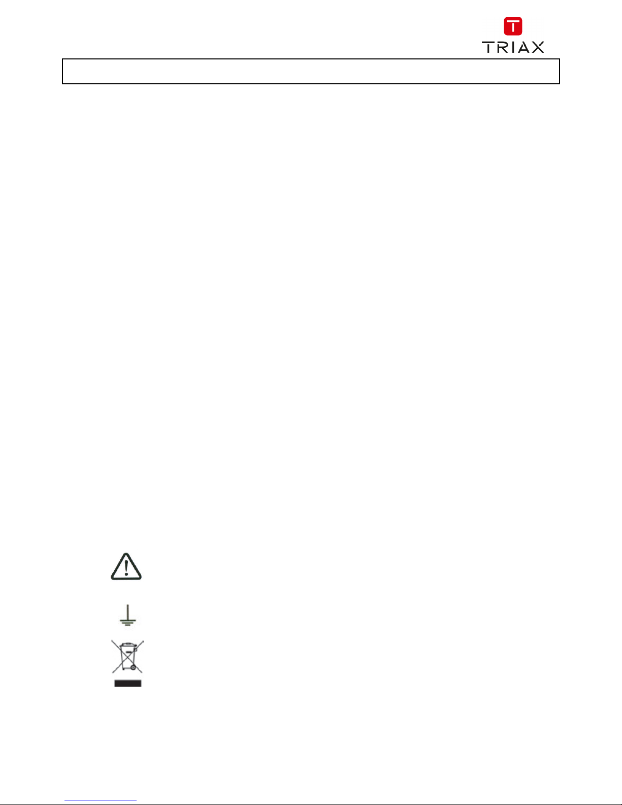
Press button ON/OFF
RF connector for use with an
F/F adaptor provided with the
appliance.
Page 10
FIELD METERS MCT 080 / 081 / 082 / 085 USER MANUAL
p. 9
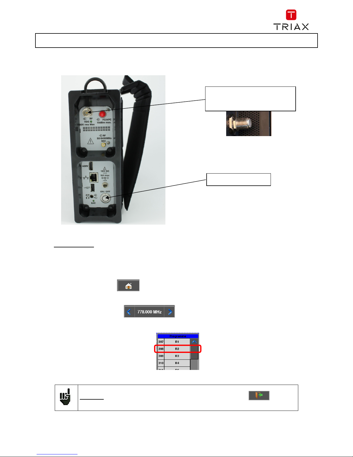
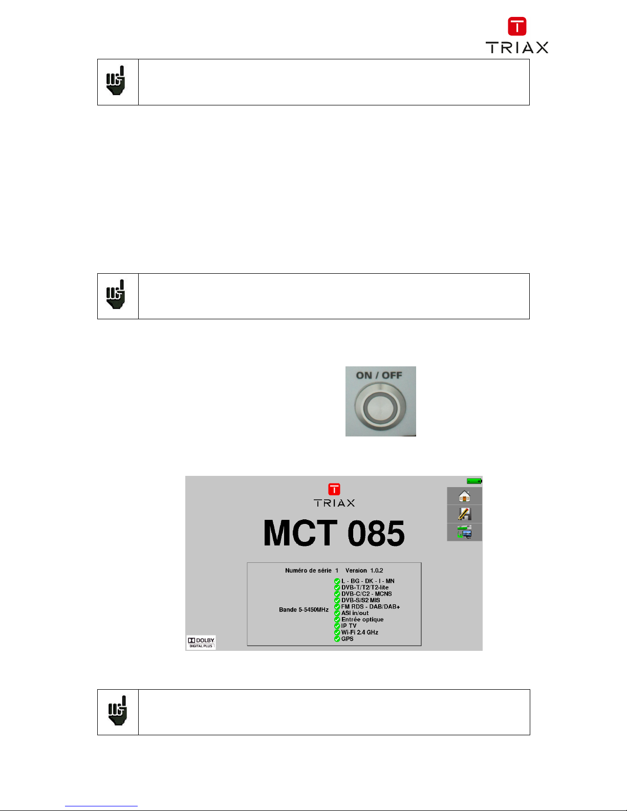
Welcoming page:
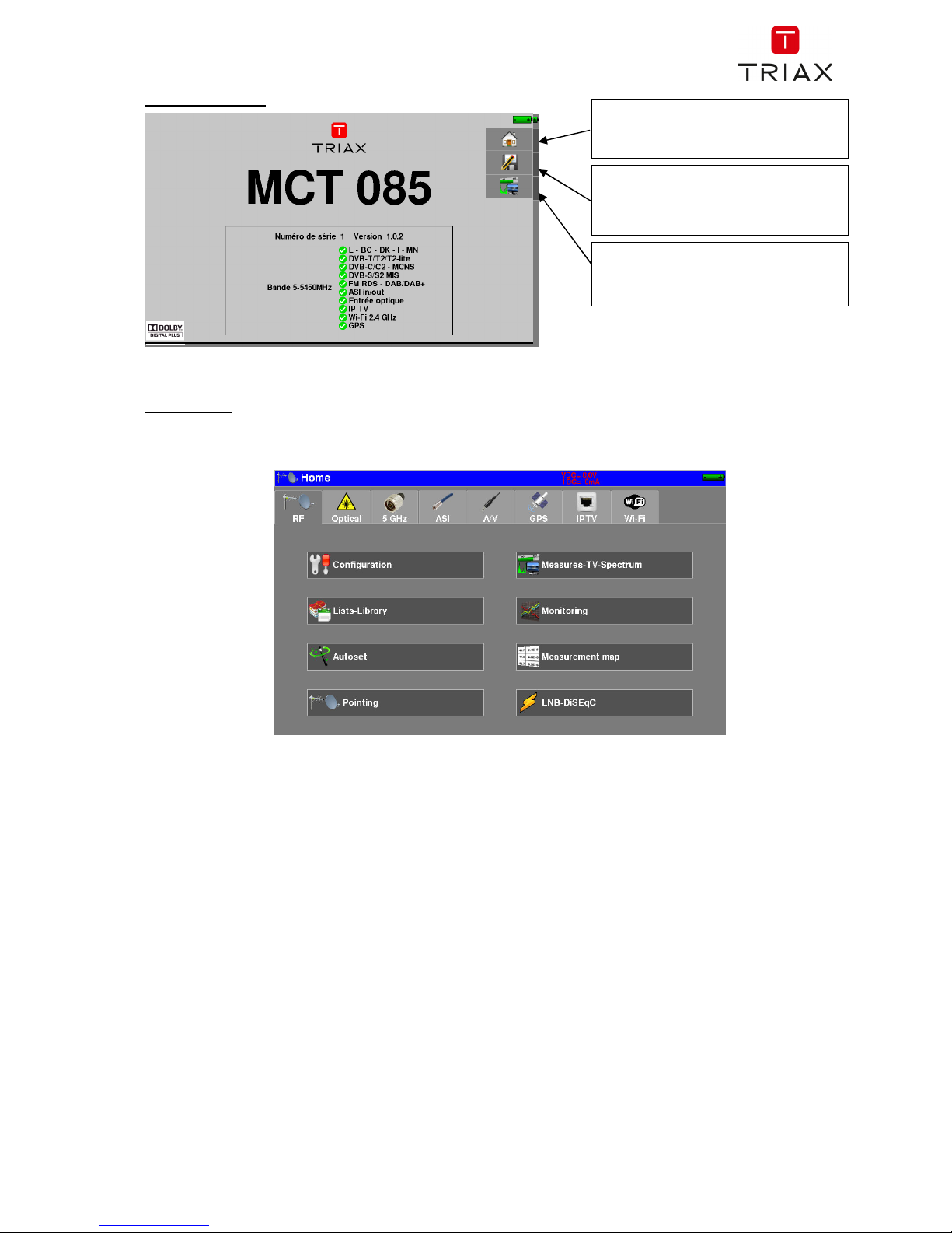
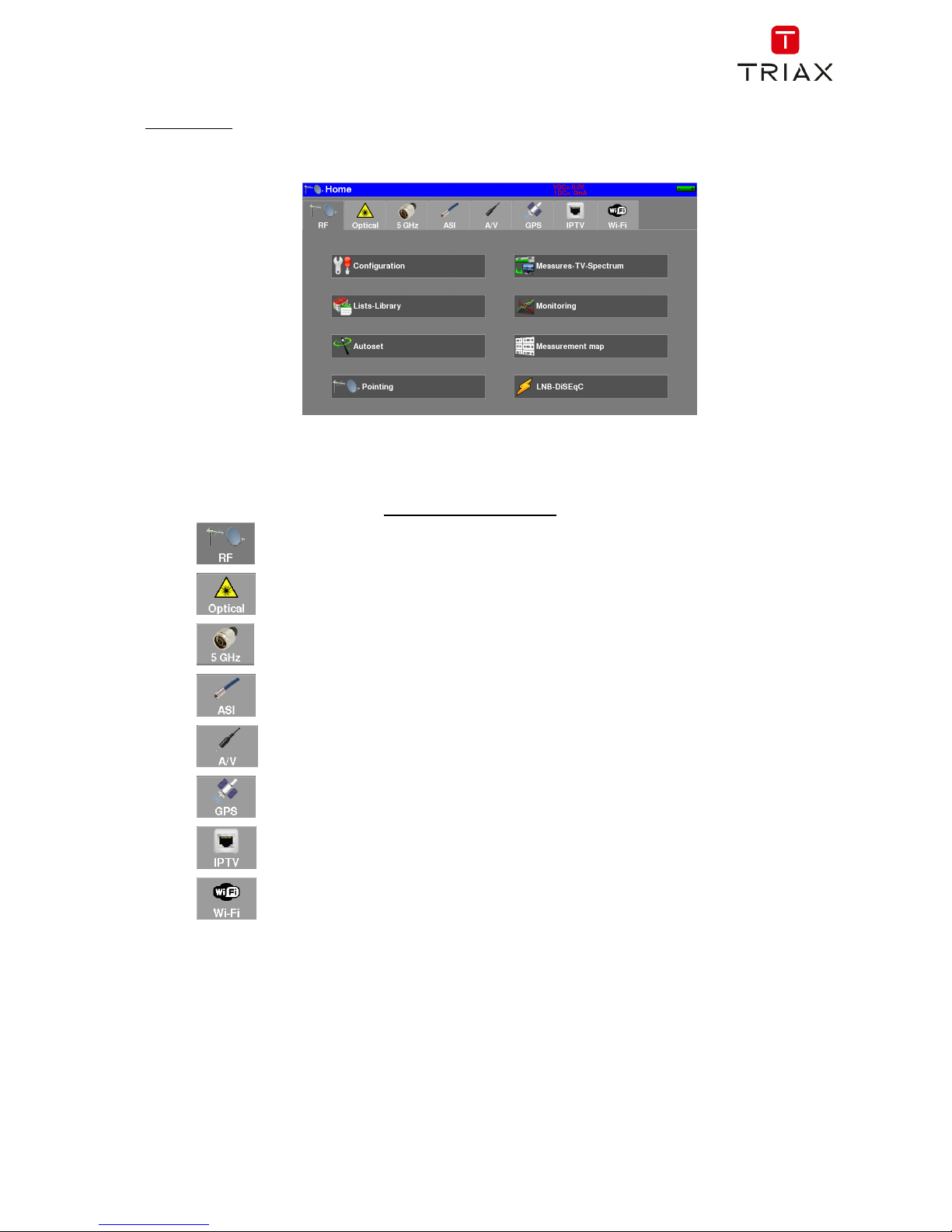
Home page :
The functions of the device are grouped by type: choose the category in this page by selecting a tab; the
possible functions will then be accessible.
HOME
Access to the main menu Home
SAVE
current page Save
Measures-TV-Spectrum
Access measurements
Page 11
FIELD METERS MCT 080 / 081 / 082 / 085 USER MANUAL
p. 10
2.2 Signal spotting
The MCT08x allows spotting signals in terrestrial or satellite very quickly.
In the following chapter, we will see how to spot a signal on three types of installation:
checking of a terrestrial antenna (the installation has already been made)
installation of a terrestrial antenna
installation of a satellite dish
2.2.1 Checking a terrestrial antenna
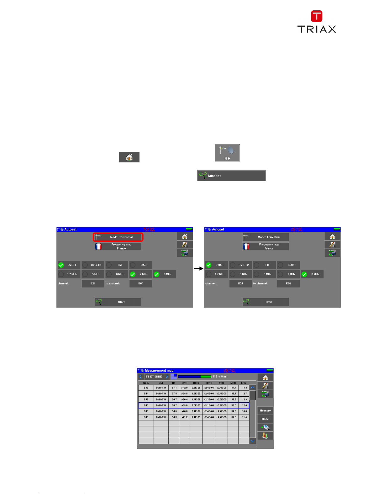
In this case, the “Autoset” function allows a “scan” of the channels that the antenna detects.
Plug the cable of your antenna to the MCT08x (take care to use an adequate adaptor)
Turn your appliance on.
Press the “Home” key , then choose the tab “RF”
The Home page appears on screen. Press “Autoset”
On this page, press “Mode”, “Terrestrial”, then select DVB-T and 8MHz (as here below)
The scan should range from the E2 to the E69 channels, frequency range Europe (you may reduce the
number of channels to scan if you know the range of the emitter where the antenna points at: the scan will
be faster)
Press “START”, the appliance starts a search.
At the end of the scan, it turns directly to the “Measurement Plan” mode. If channels were found, the
appliance makes measurements continuously (level, C/Nl, BER/MER) on the detected channels.
Page 12
FIELD METERS MCT 080 / 081 / 082 / 085 USER MANUAL
p. 11
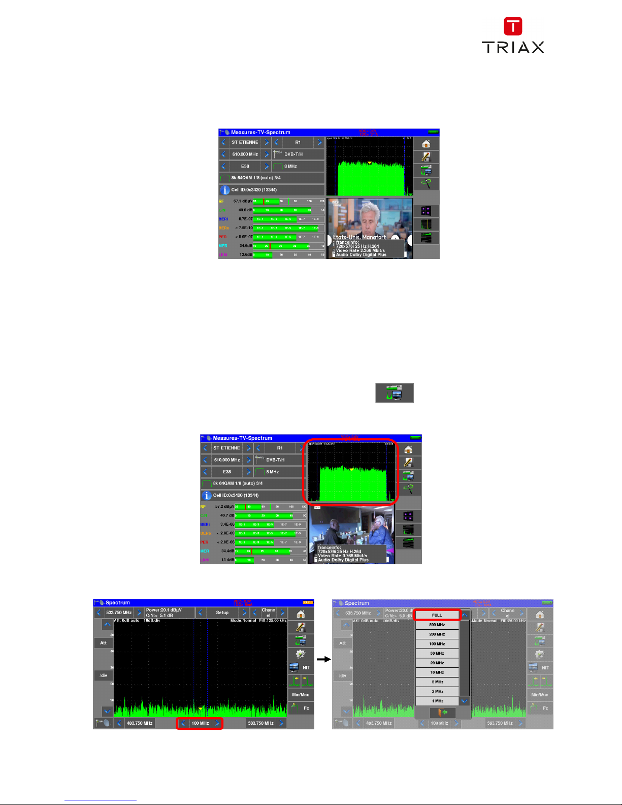
Eventually, press the “Measures/TV/Spectrum” key; on this new page, select the channel that you want to
display.
The instrument display on a single page of parameters of the signal, TV picture and Spectrum scan : a great
time gain for your installs.
2.2.2 Installation of a terrestrial antenna
To install a terrestrial antenna, two ways are possible :
Spectrum function use
Pointing function use
2.2.2.1 Using Spectrum function
Plug the cable of your antenna to the MCT08x (take care to use an adequate adaptor)
Turn your appliance on. Press the “Measures-TV-Spectrum” key
Press the “Spectrum” area
Access to full SPAN mode
Page 13
FIELD METERS MCT 080 / 081 / 082 / 085 USER MANUAL
p. 12
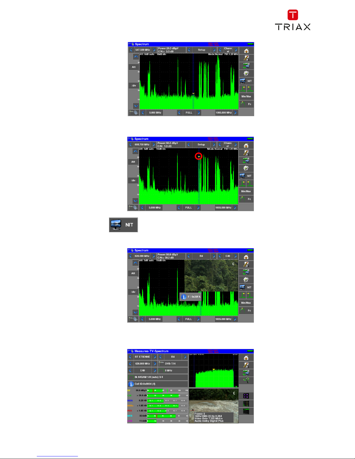
Adjust the antenna to get the most powerful signal possible
Press directly the signal you want in the spectrum (the cursor moves to where you press)
Press the NIT/TV key , the device find automatically all the parameters of the signal.
Once the search ended, the device display TV picture, TV name, “Network Name” and “Network ID”.
Press the “Measures-TV-Spectrum” key. You can now display the level, the BER/MER, the TV picture (with
information about the current service) and the spectrum of the signal selected on the same page…
Page 14
FIELD METERS MCT 080 / 081 / 082 / 085 USER MANUAL
p. 13
2.2.2.1 Using Pointing function
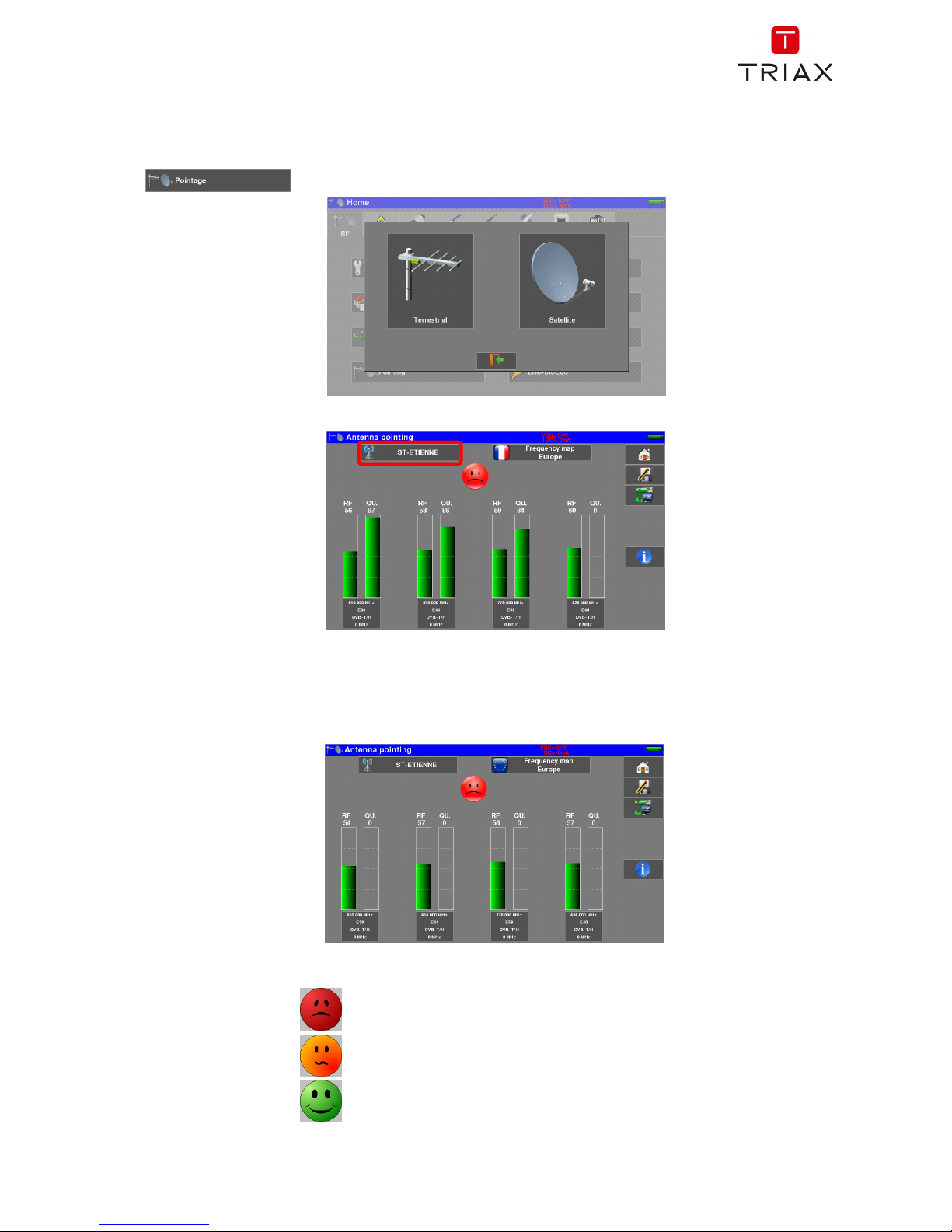
The device has a terrestrial pointing function to quickly and easily adjust your terrestrial antenna.
Access the terrestrial pointing menu from the "HOME" page by pressing the key« Pointing »
, puis « Terrestrial »
The following page appears :
Choose the transmitter to point in the list
If your transmitter is not in the list, if you want to enter a new transmitter, please refer to chapter 9.1
Once you have completed the four channels, turn the antenna slowly until you hear the melody and get the
maximum quality
No channels found → Red Smiley
Average reception quality → Orange smiley
Good reception quality → Green Smiley
Page 15
FIELD METERS MCT 080 / 081 / 082 / 085 USER MANUAL
p. 14
2.2.3 Installation of a satellite dish
To install a satellite antenna, two ways are possible :
Spectrum function use
Pointing function use
2.2.3.1 Using Spectrum function
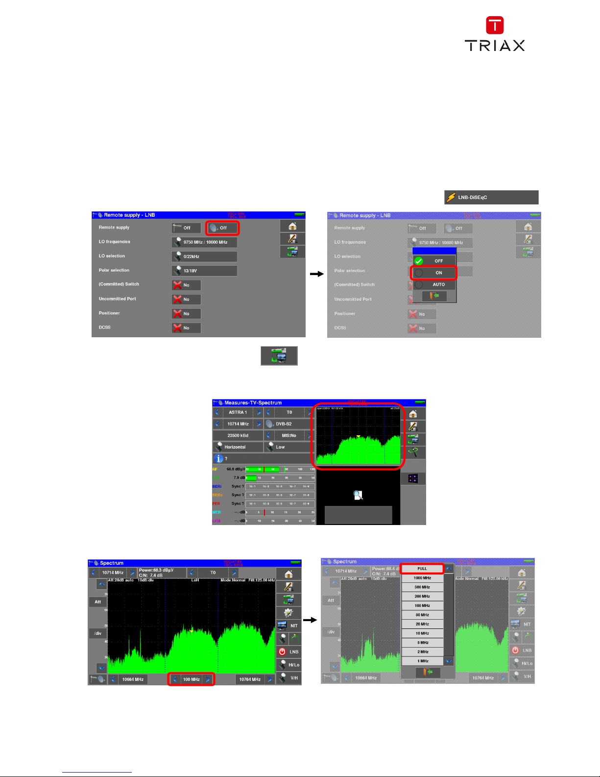
Connect the satellite dish to the appliance.
Activate the remote power supply
To access to the Remote power supply page, press “Home” and then “LNB-DISEQC”
Press key « Measures-TV-Spectrum »
Press the “Spectrum” area (see below)
Access to full SPAN mode
Page 16

FIELD METERS MCT 080 / 081 / 082 / 085 USER MANUAL
p. 15
Adjust the antenna to get the most powerful signal possible
Press directly the signal you want in the spectrum (the cursor moves to where you press)
Press the NIT/TV key , the device find automatically all the parameters of the signal.
Once the search ended, the device display TV picture, Satellite name, and “Network ID”.
Press the “Measures-TV-Spectrum” key. You can now display the level, the BER/MER, the TV picture (with
information about the current service) and the spectrum of the signal selected on the same page…
Page 17
FIELD METERS MCT 080 / 081 / 082 / 085 USER MANUAL
p. 16
2.2.3.2 Using Pointing function
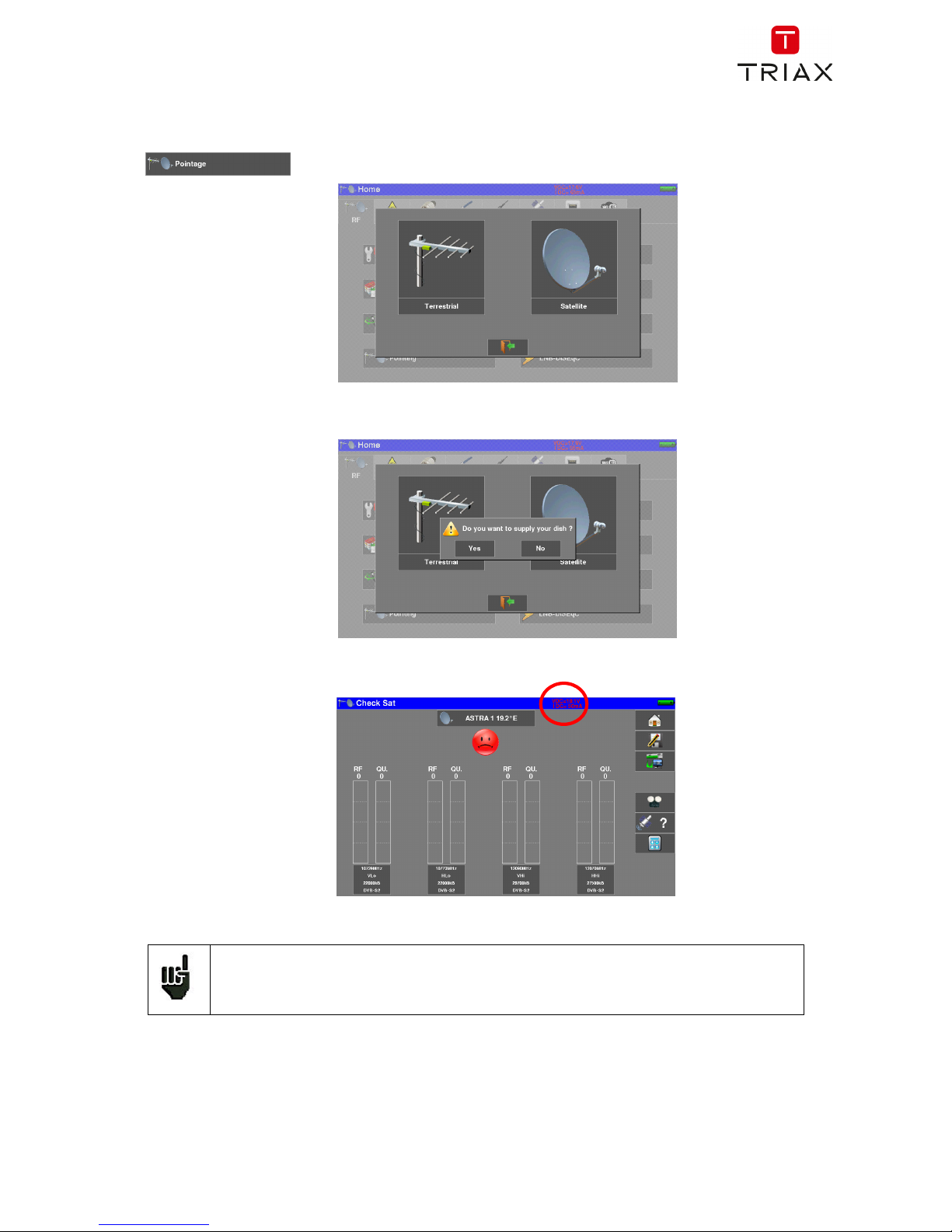
The device has a satellite pointing function to quickly and easily adjust your dish.
Access the satellite pointing menu from the "HOME" page by pressing the key« Pointing »
, then “Satellite”.
The device proposes to activate the remote power supply :
The following page appears:
Check the indication of consumption on the remote power supply; zero consumption
indicates a failed LNB, or a cut coaxial cable, for example.
Page 18
FIELD METERS MCT 080 / 081 / 082 / 085 USER MANUAL
p. 17
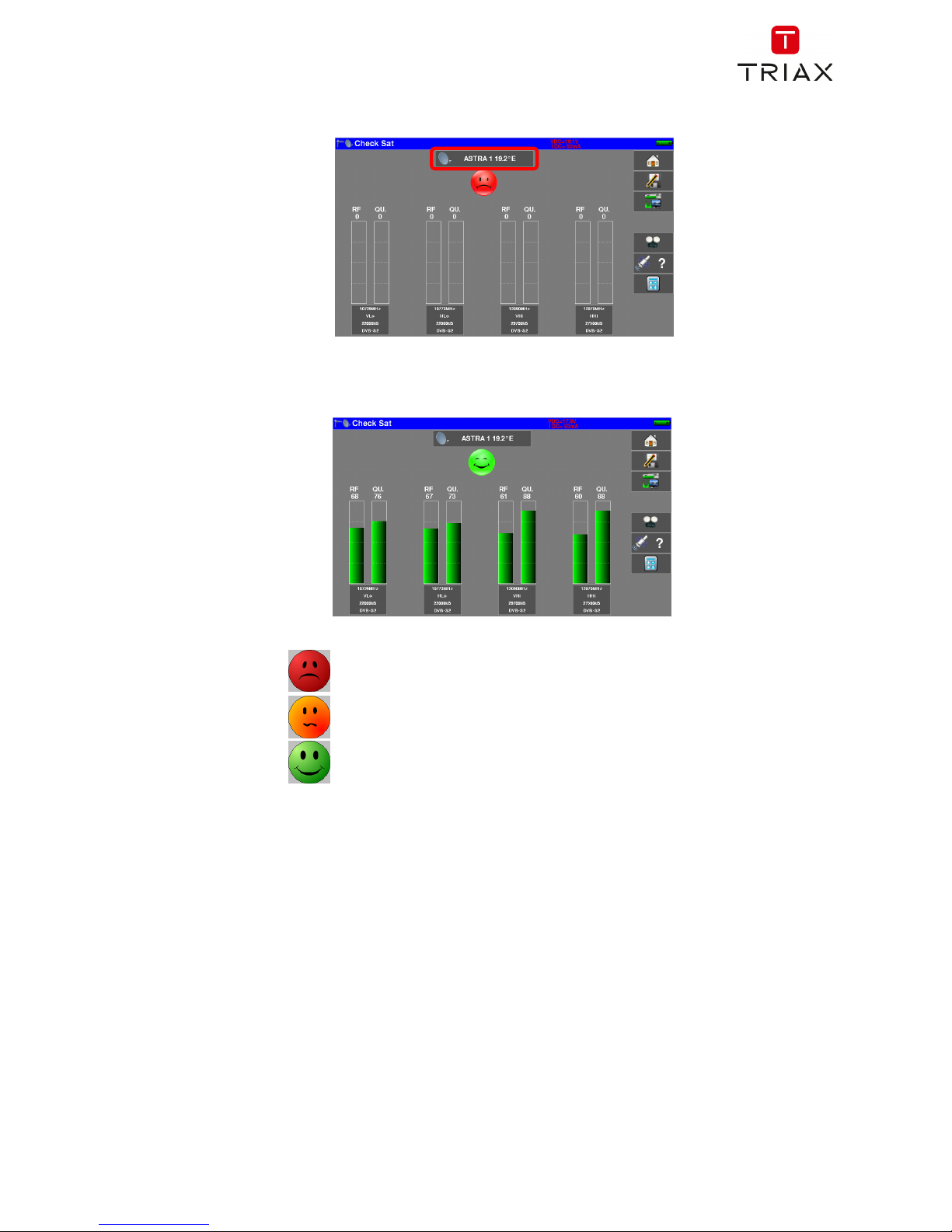
Select a satellite like in the example below (here Astra1):
If your satellite is not in the list, if you want to enter a new satellite, refer to chapter 9.2.
Slowly orientate the satellite dish until hearing the locking melody and getting the best quality
No found transponder → red smiley
Average reception quality → orange smiley
Good reception quality → green smiley
Reminder: transponder = satellite channel
Page 19
FIELD METERS MCT 080 / 081 / 082 / 085 USER MANUAL
p. 18
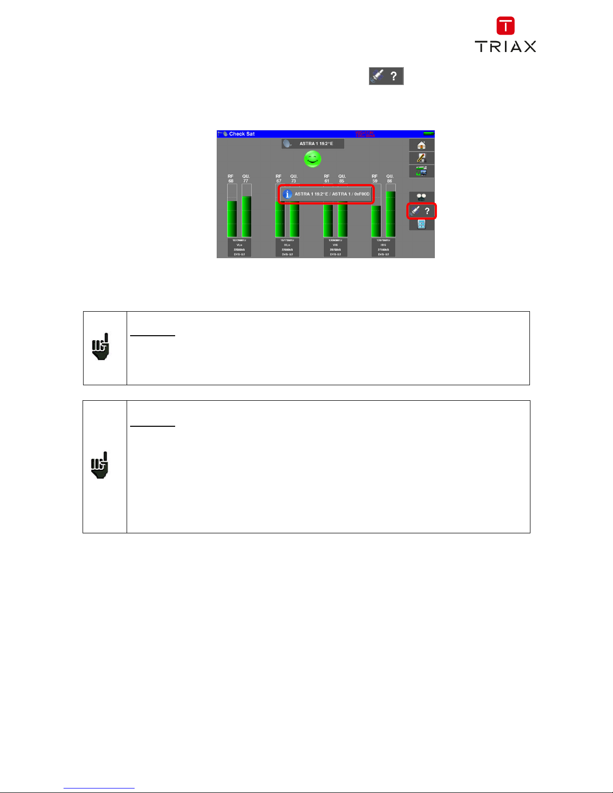
To check if the aimed satellite is the right one: press the “NIT key”
The appliance searches the MPEG NIT table on one of the 4 transponders and displays the name of the
satellite:
Attention:
To identify a satellite, you must be « hooked » on all 4 transponders. (Quality > 0)
However, some transponders are regularly modified. See the frequency range of the
satellite when a transponder does not seem to work.
Some switches or LNB work only with DiSEqC commands. In this case, position the
band (OL) and the polarization on DiSEqC at the Configuration page LNB-DiSEqC.
(Attention: the Check Sat is slower when using the DISEqC command).
For any additional information, our technical support is at your disposal:
Attention: The displayed name depends on the content of the MPEG NIT table.
Some distributors provide no (or poor) such table.
The displayed information may be wrong.
Page 20

FIELD METERS MCT 080 / 081 / 082 / 085 USER MANUAL
p. 19
3 Presentation
3.1 General
The field strength measurers MCT08x are handy appliances designed for the installation and maintenance of
any broadcasting and reception installations of analogical and digital terrestrial television channels, satellites
or cable networks.
The band ranges between 5 MHz to 2200 MHz; this allows accurate measurements on all analogical
television standards, FM carrier waves and the various digital standards DVB-C/C2, DVB-T/T2/T2Lite,
DAB/DAB+, DVB-S/S2, DSS.
They do Level measurements in average, peak and power according to the selected standard.
In Measurement Plan mode, they scan up to 50 setups at the same time and compare them to decision
levels (min / max).
Equipped with an efficient Bit Error Rate measurement (various BER, MER), they allow the full validation of
digital transmissions DVB-T/T2/T2Lite, DVB-C/C2, DAB/DAB+, DVB-S/S2 and DSS.
Providing a Constellation diagram for digital standards, the detection and display of Echoes and pre-
echoes and the display of MER per carrier in DVB-T/T2/T2Lite and DVB-C2 to have a complete analysis of
the digital signals.
The Spectrum analysis, quick and accurate, allows the display of the disturbances and the measurement of
C/N, power...
You can display the digital TV terrestrial or satellite under SD or HD, on standards MPEG2, MPEG4, and
HEVC.
The visualization of the terrestrial analog TV image is also possible, in RF signal or CVBS video input.
The Measures-TV-Spectrum mode allows the simultaneous display of level, spectrum and of video of the
same signal.
A HDMI socket allows the transmission of the TV picture to an external monitor.
The sound is audible through the built-in speakers, as well as available on the Jack headphone socket.
Designed for use on field, they are compact (less than 3 kg, battery included), autonomous (battery pack and
quick charger), equipped with a LCD 10’’ touchscreen (capacitive).
The high memory content allows the storage of many configurations, measurements and spectrum curves.
Each appliance is fully remote-controlled through ETHERNET connection via a computer.
Page 21
FIELD METERS MCT 080 / 081 / 082 / 085 USER MANUAL
p. 20
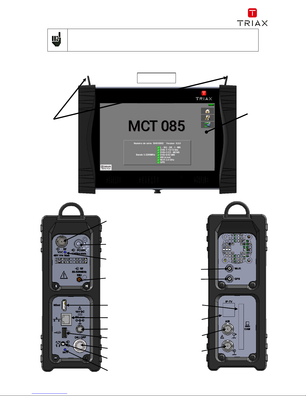
Attention : MCT080 - MCT081 - MCT082 - MCT085
Consult the Selection Guide to know the possibilities of your device.
3.2 Description of the appliance
Fastening
for straps
10’’
capacitive
touchscreen
high
resolution
FRONT VIEW
ON/OFF
switch
ASI OUT socket
IPTV input
DVB-CI CAM
(encrypted TV )
RF input
GPS input socket
Remote supply light
USB socket
Ethernet socket
HDMI socket
External power socket
Charging indicator
light
Optical Fiber input
5GHz RF input
AV Jack socket
WiFi input socket
ASI IN socket
Page 22
FIELD METERS MCT 080 / 081 / 082 / 085 USER MANUAL
p. 21
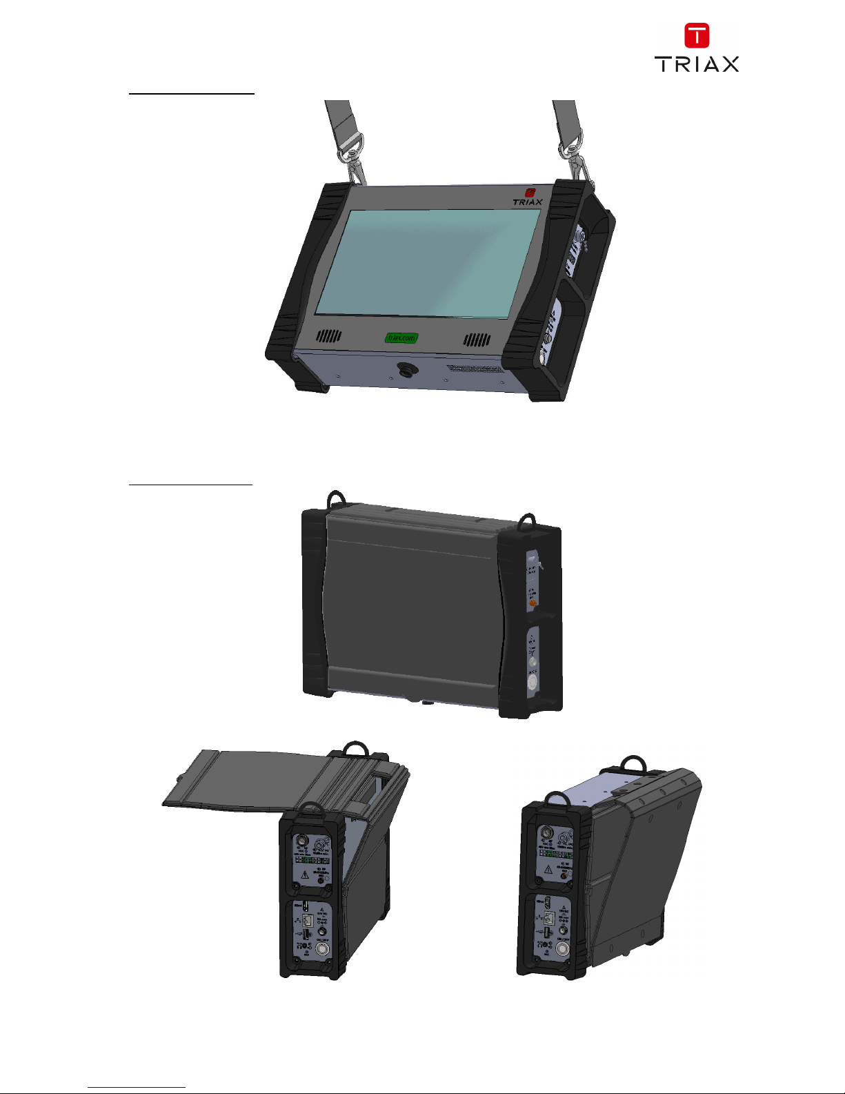
How to use the belts
Use of the sun visor
Page 23
FIELD METERS MCT 080 / 081 / 082 / 085 USER MANUAL
p. 22
4 Power-up
All the material is checked before shipment and delivered in an adapted packaging. There is no particular
unpacking instruction.
The appliance is equipped with a Lithium-Ion (Li-ion) battery. It is shipped with the battery loaded.
However, if the appliance has remained idle more than one month long, check its charge state and reload
if required.
4.1 Battery
Attention: Any intervention on the battery requires the disassembly of the appliance and
should be made by a TRIAX technician.
Use only batteries provided by TRIAX.
Security advice:
Do not throw into the fire or heat up the battery pack
Do not shunt the parts of the battery: risk of explosion!
Do not drill
Do not disassemble the battery pack
Do not reverse the polarities of the battery
This battery pack includes a protective item that should not be damaged or removed
Protect the pack from the heat while storing
Do not damage the protective sheath of the pack
Do not store the appliance in a vehicle under sunlight
Used batteries are not for domestic waste; lithium batteries should be recycled.
The battery has a 200-charge-discharge cycle life or 2 years.
Advice to extend the life of your battery:
Avoid deep discharges
Do not store the batteries too long without using them
Store the battery around 40% loading
Do not fully charge or fully discharge the battery before storage.
When the battery is almost fully discharged, the appliance will warn “Low battery”, then will shut
off after a few minutes.
4.2 Charging battery
To charge the battery inside the appliance:
Connect the external power supply provided through the jack plug of the appliance (on the right
side)
Connect the power supply on the mains
The internal charger starts charging the battery; the green lamp lights up.
Page 24
FIELD METERS MCT 080 / 081 / 082 / 085 USER MANUAL
p. 23
Loading will be faster if the appliance is off but will work if the appliance is on. Once the
battery loaded, the lamp will shut off automatically.
Discharge the appliance only with the provided power supply block.
The battery is 80%-loaded after 1 hour 50 minutes.
The total charge is reached after 2 hours 40 minutes.
The autonomy is set in terrestrial mode at 50% brightness, without remote power supply, interfaces not
connected, sound at 10%
4.3 External power supply
The appliance works under 15V (4.6 A) power supply.
The power supply block provided is an external power supply too.
Only use the power supply block provided with the appliance.
Using another power supply could damage your device and void the warranty.
4.4 Turning the appliance on and off
Press the button on the right side of the appliance:
The entry page appears on screen.
The message “Autotest: running” is shortly displayed, then disappears.
Pressing this button turns the appliance off.
The ON/OFF button lights up when the appliance is working.
Pressing the ON/OFF button for a long time forces the shut-off of the appliance;
proceed this way only in case of necessity.
Page 25
FIELD METERS MCT 080 / 081 / 082 / 085 USER MANUAL
p. 24
5 Man-machine interface
5.1 Content of the screen
MCT08x is an appliance with a capacitive touchscreen. This requires a soft handling. No glove and no stylus
should be used, so that the triggering should be taken into account.
You will recognize the « keys » by their dark grey color.
Example the home key:
Some parameters can be modified step by step : use the arrows close to the parameter value.
Example of frequency :
You can also select lines in tables.
Presentation page :
Windows :
Attention: To display a window like this one below, you have to press the key
Home
Access to the main
menu page
Save
Access to the save of
the current page
Measures-TV-Spectrum
Access to the
Measures/TV/Spectrum
page
Page 26
FIELD METERS MCT 080 / 081 / 082 / 085 USER MANUAL
p. 25
Home page :
The functions of the device are grouped by type: choose the category in this page by selecting a tab; the
possible functions will then be accessible.
“Home” page allows the navigation through all functions of the appliance.
We find the categories related to the measurement input used:
access to measurements on the RF input socket (levels, BER / MER, spectrum, TV, ...)
access to measurements on the Fibre Optic input (power, demodulation, ...)
access to measurements on RF input 5GHz (levels, BER / MER, spectrum, TV, ...)
access to measurements on the input ASI (TV, ETR290, ...)
access to the measurements on the Audio / Video input (TV, ...)
access to GPS-related measurements (cartography, reception, ...)
access to measurements on the IPTV Ethernet input (IAT, TV, ...)
access to measurements on the Wi-Fi input (levels, SSID, ...)
Page 27
FIELD METERS MCT 080 / 081 / 082 / 085 USER MANUAL
p. 26
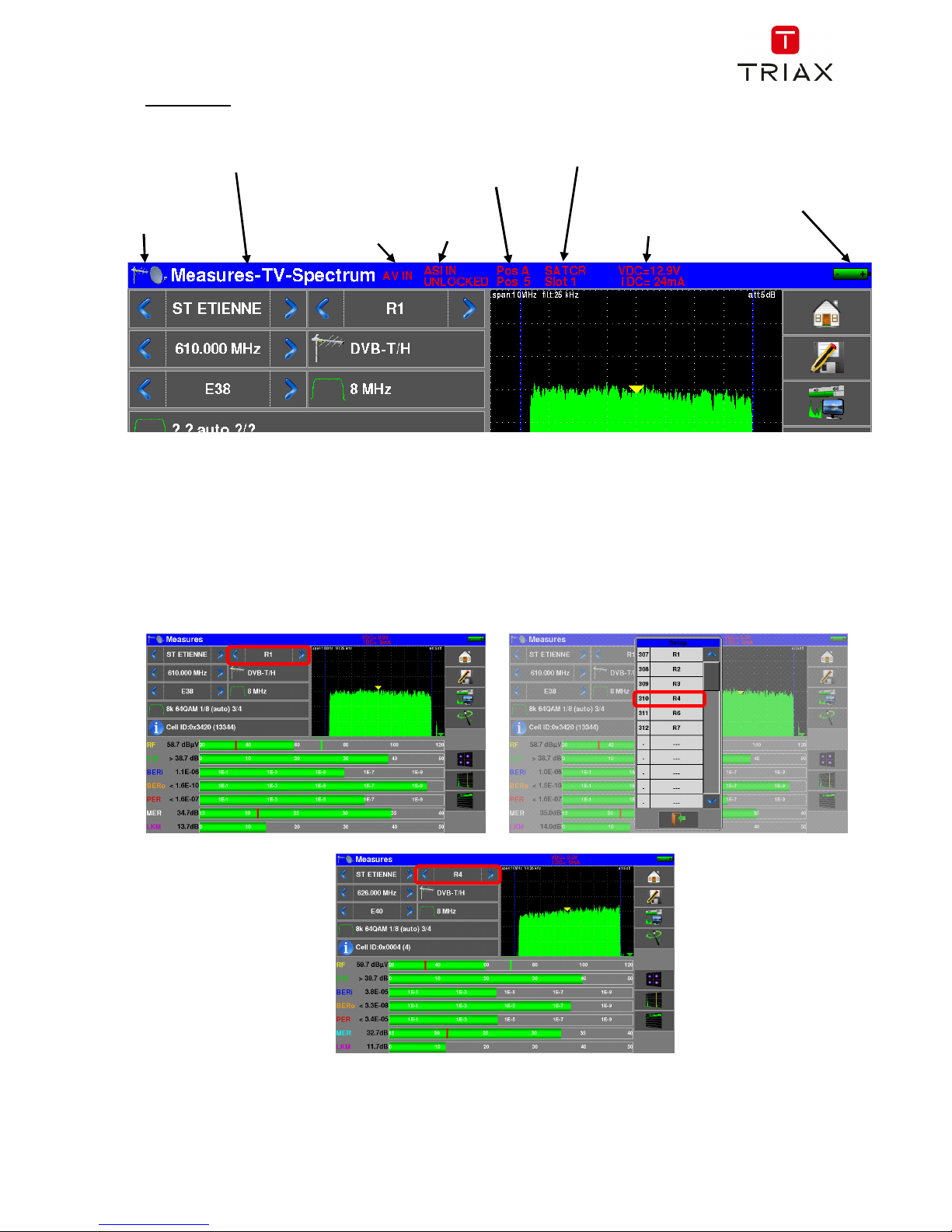
Information:
On all pages is displayed the following information :
5.2 Changing a name or a value
5.2.1 Change inside a table
You can select a setup in the table. In this case, you can validate a setup by pressing the line you want to
display
In this example, you change from the TNT-R1 setup to the TNT-R4 in the Measure page:
Voltage
and
Current
of
the remote power
supply
I
ndication of
the state of
the battery
Title of the pa
ge
ASI input
DISEQC switches
Icon to recall
measurement
input choice
SATCR
mode
Current Slot
External
video
Page 28
FIELD METERS MCT 080 / 081 / 082 / 085 USER MANUAL
p. 27
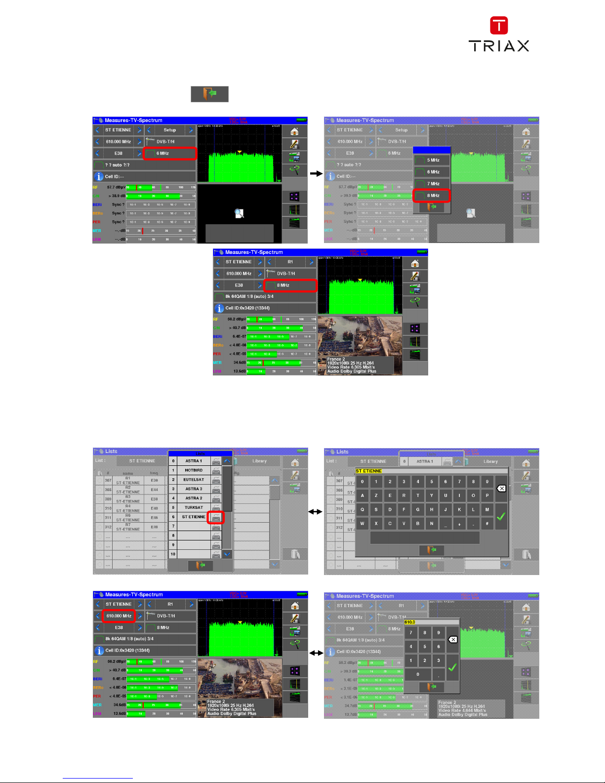
5.2.2 Change with selection
When pressing a key, you may have a window with multiple choice. You only have to press the value you
want to validate it. The key allows you to cancel and exit this window, like in the example below.
In this example, the bandwidth changes from 6 to 8 MHz:
5.2.3 Change with virtual keyboard
If you want to enter a name of a number,
press on the “keyboard” symbol on the line you want to change :
or on the numeric value you want to change :
Page 29
FIELD METERS MCT 080 / 081 / 082 / 085 USER MANUAL
p. 28
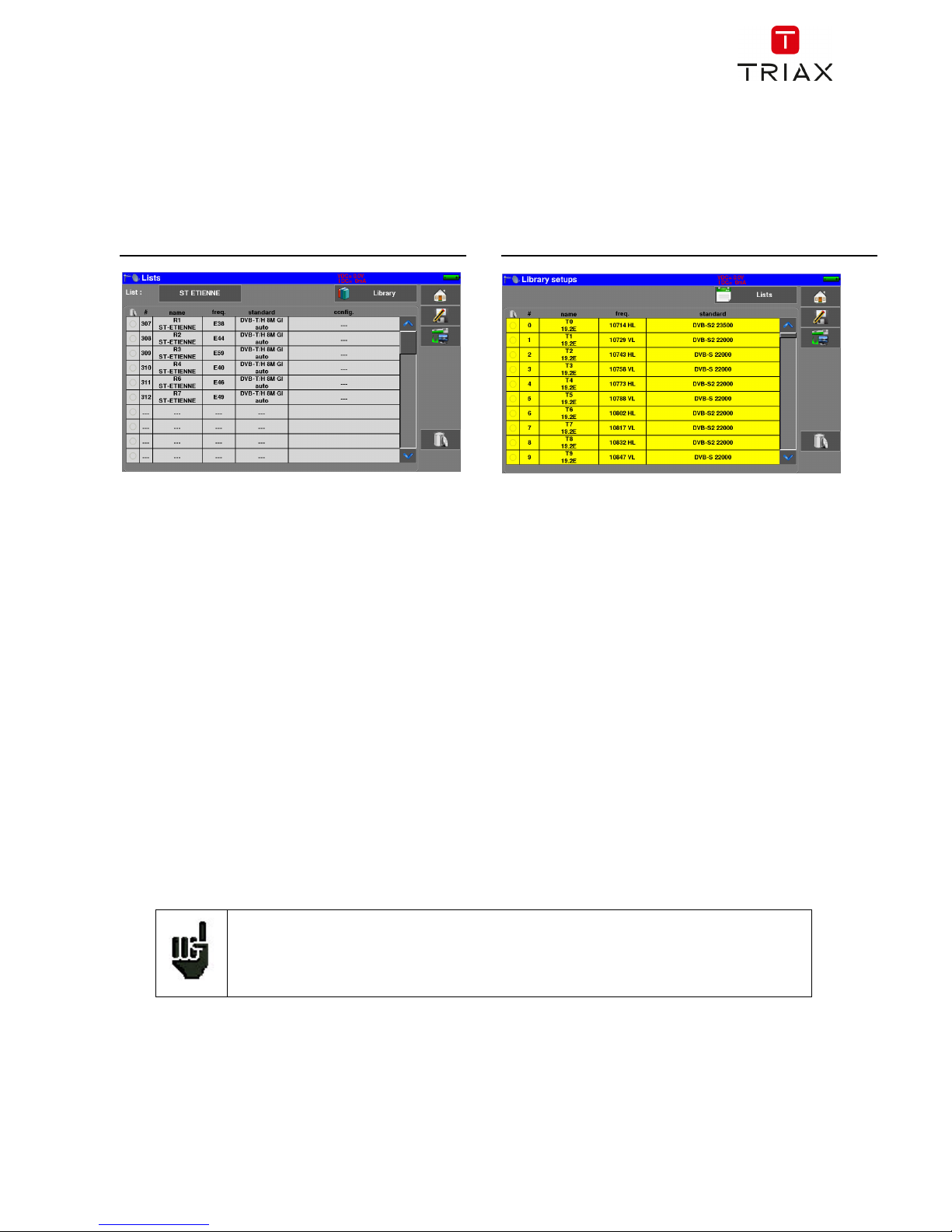
5.3 Lists of measurements and setup library
In order to make easier the recall of data on field, the appliance uses 20 Measurement Lists of each 50
lines and a Library of 1000 setups.
A setup corresponds to a terrestrial, cable or satellite emission.
A list of measurements corresponds to a particular installation: presence of several satellite dishes, of
various switches…
The same setup may be used in several measurement lists.
The same installation may use two satellite dishes
ASTRA 19.2 in DiSEqC position A
HOT BIRD 13 in DiSEqC position B
Another one may use three satellite dishes
ATLANTIC BIRD 3 in DiSEqC position A
ASTRA 1 in DiSEqC position B
HOT BIRD in DiSEqC position C
The same setup may be used several times in the same measurement list.
ZDF SatCR slot 0
ZDF SatCR slot 1
ZDF SatCR slot 2
ZDF SatCR slot 3…
If a parameter of a setup changes, for example a modification of rate or change from DVB-S to DVB-S2, only
the setup inside the library should be updated.
These lists and setups may be created on a computer thanks to TR7837 free software,
and loaded to the appliance through a USB stick.
Example of list (the background of the table is white) Example of library (the background of the table is yellow)
Page 30
FIELD METERS MCT 080 / 081 / 082 / 085 USER MANUAL
p. 29
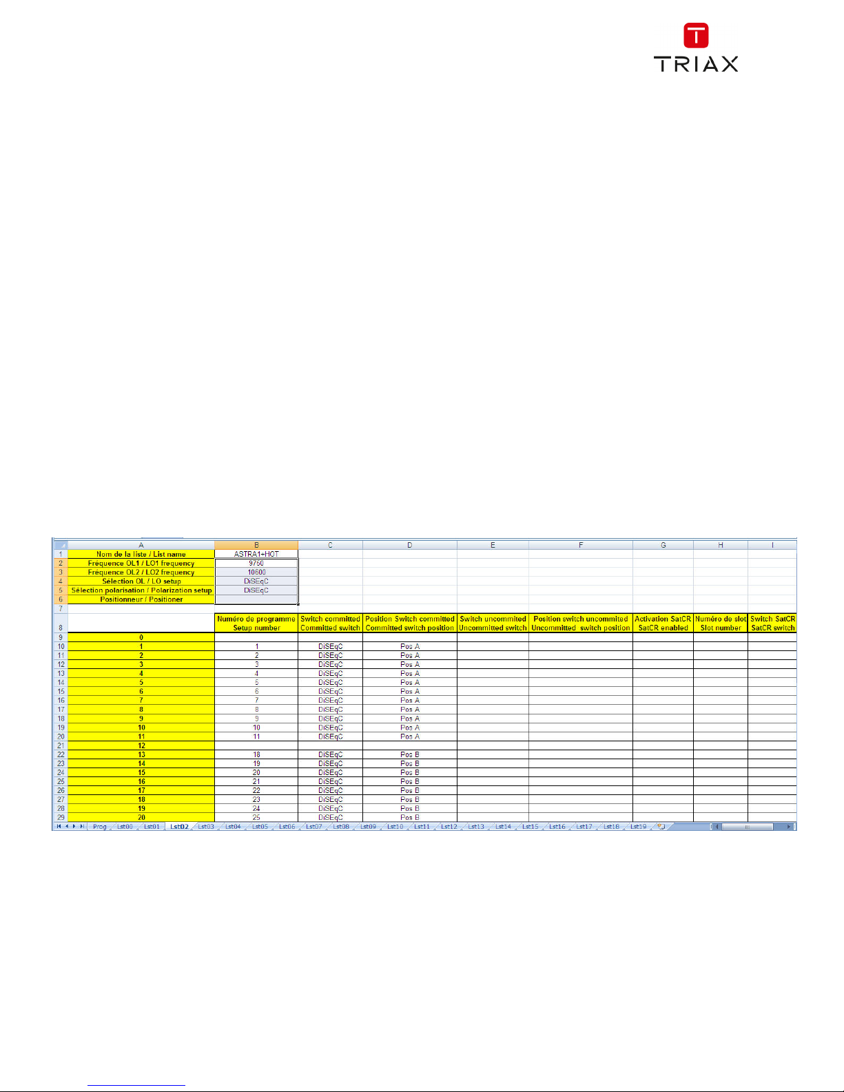
A list of measurements is made of:
a list name in 10 characters
the lowest frequency of the LNB (OL1)
the highest frequency of the LNB (OL2)
the selection mode low band / high band of the LNB
the selection mode of the polarization
the presence of the position number of the positioner (motorized satellite dish)
50 lines including each:
a setup number corresponding to the setup list
the presence and the functioning mode of the switch, committed type
the position of the switch, committed type
the presence and the functioning mode of the switch, uncommitted type
the position of the switch, uncommitted type
the presence of SatCR equipment
the SatCR slot number
the position of the SatCR switch
A few of these parameters are specific to the waveband of the satellite and have no influence in terrestrial
and cable modes.
Presentation of a measurement list in TR7837 :
A setup is made of:
a setup name in 8 characters
a place name in 10 characters
a frequency
a channel number in terrestrial or cable mode
a frequency map in terrestrial or cable mode
a vertical or horizontal polarization in satellite mode
a low or high LNB band in satellite mode
Page 31

FIELD METERS MCT 080 / 081 / 082 / 085 USER MANUAL
p. 30
a standard
an analogical mono stereo or NICAM mode in terrestrial or cable mode
a constellation type 64QAM 256QAM under DVB-C and J83B
a bandwidth 5, 6, 7 or 8 MHz under DVB-T and DVB-T2
a symbol rate under DVB-C, J83B, DVB-S, DVB-S2 or DSS
a value for the guard interval under DVB-T and DVB-T2
the inversion or not of the spectrum under DVB-T
According to the terrestrial, cable or satellite band mode and to the standard, some parameters have no
influence.
The place name may distinguish two distinct emitters, example TF1 Fourvière and TF1 Chambéry.
Frequency and channel number are equivalent: a valid channel number has priority over a frequency.
The frequency map parameter associated with the setup allows frontiersmen to keep on using channel
numbers.
Presentation of a setup library in TR7837 :
Selecting a list in the Lists page automatically recalls all information associated with this
list.
Selecting a Setup on a measurement page automatically recalls all information associated
with this setup.
Page 32

FIELD METERS MCT 080 / 081 / 082 / 085 USER MANUAL
p. 31
6 Measurement lists
6.1 The List page
In this page, you can select the list where you will work on measurements.
Pressing Home then Lists-Library gives you access to the
Lists function:
Lists are ranked from 0 to 19. To select the list you want, press the following the name of the list.
Available Lists are displayed. Press the one you want:
In this example, we selected ST ETIENNE.
Page 33

FIELD METERS MCT 080 / 081 / 082 / 085 USER MANUAL
p. 32
6.2 Modification of a list
To change the name of a list, you must trigger its name.
A virtual keypad shows up, type the new name.
To add a setup to the list, select the line. A window shows up:
By pressing the key before Setup, you disclose the available setups from the library (you cannot create a
setup from a list; to create a setup, see Setup creation or modification in the library):
Attention: A list may contain booth Satellite and Terrestrial setups.
Attention: If the line contains a setup, it shall be erased. To cancel, press:
Page 34

FIELD METERS MCT 080 / 081 / 082 / 085 USER MANUAL
p. 33
Scroll the list up or down to find the setup you want to add to your list. Press the line you want:
The setup is now in the list:
You may erase one or all setup(s) from the list :
mark on the left all lines to be deleted:
Then simply press the trash and validate your choice:
In a satellite setup, you can change the Switch, the Uncommitted Port and the DCSS by activating any of
these keys (this change will affect only the setup in this list, not in the library):
Page 35

FIELD METERS MCT 080 / 081 / 082 / 085 USER MANUAL
p. 34
7 Setup library
7.1 The Library page
By pressing Home then Lists-Library , you can access the Lists
function. From there, you can access the Library by pressing the key:
7.2 Creation or modification of setups in the library
To create or change a setup in the library, you have to select a line in the table. A window pops up:
From this window, you can create a terrestrial, satellite KU, L or C setup.
First choose the Standard of the program you want to create; you will then have access to para-meters
related to the standard.
To proceed, see chapter “
Man-machine interface “
Attention: If the line contains a setup, it will be erased. To cancel, press:
Page 36

FIELD METERS MCT 080 / 081 / 082 / 085 USER MANUAL
p. 35
Terrestrial setup:
Under standard DVB-T/H (DVB-T2 identical, except modulation)
Under standard DVB-C
In terrestrial analogical standard (L, BG, DK, I and MN)
To enter the
frequency band you
want for the setup
To enter the place
name you want for
the setup
To enter the name you
want for the setup
To enter the frequency
you want for the setup
To enter the
channel you
want for the
setup
To enter the standard
you want for the setup
(DVB-T/H in this case)
To enter the symbol rate
you want for the setup
To enter the type of audio
configuration you want for
the setup (mono, stereo or
NICAM)
Page 37

FIELD METERS MCT 080 / 081 / 082 / 085 USER MANUAL
p. 36
Setup Satellite KU, L or C:
Ku, L, or C corresponds to the satellite band of the setup
To enter the type of polarity
you want for the setup (high
or low, vertical or horizontal)
To enter the symbol rate you
want for the setup
Page 38

FIELD METERS MCT 080 / 081 / 082 / 085 USER MANUAL
p. 37
8 AUTOSET mode
Attention: The Autoset channel research is only possible when at least one list is empty
with enough place in the library
This mode allows an automatic research of setups and to provide information about the current place.
You can access it through the key on page “Home”.
The displayed lines on this page depend on the selected Frequency band : terrestrial, cable or satellite
mode:
Terrestrial Mode Satellite Mode
Cable Mode
Page 39

FIELD METERS MCT 080 / 081 / 082 / 085 USER MANUAL
p. 38
Once the mode selected, the keys of the various parameters activate or deactivate each option.
A green check shows that the parameter is included in the research. If there is no green check, the
parameter will not be taken into account for the research.
Active research parameter
Inactive research parameter
Attention: The more you select options, the longer the research.
8.1 Terrestrial mode
This mode allows automatic research on the terrestrial frequency band.
The table allows the selection of:
Standards
Channel widths
The channel range of the research
(i.e. 21 to 58).
Reducing the number of active
parameters reduces the search
time.
8.2 Satellite mode
This mode allows automatic research on the satellite frequency band.
The table allows the selection of:
Standards
LNB bands
LNB polarizations.
Page 40

FIELD METERS MCT 080 / 081 / 082 / 085 USER MANUAL
p. 39
8.3 Cable mode
This mode allows automatic research on the cable frequency band.
The table allows the selection of:
Standards
Channel widths
The channel range of the research
(i.e. 21 to 58).
8.4 «START »
No matter which mode is selected, press the “START” key when the table is filled to launch the research.
Pressing “Stop” will abort the research.
When the research is done, the appliance turns automatically to the Measurement map function.
Page 41

FIELD METERS MCT 080 / 081 / 082 / 085 USER MANUAL
p. 40
Any detected channel will be registered into the first empty list (automatically renamed AUTOSET) and
into the fist available setups of the library, starting from the end of the table.
The new list is created in the first
available list
The default name of the new list is
AUTOSET
New found channels are added one
by one into the new list
New found channels are added one
by one into the first available setups
of the library, starting from the end
of the table
Page 42

FIELD METERS MCT 080 / 081 / 082 / 085 USER MANUAL
p. 41
9 Pointing antennas
Press and to access the Pointing Antennas mode.
Then choose the antenna to point: terrestrial or satellite dish
In the case of the satellite dish, the device offers you to supply now your dish:
Page 43

FIELD METERS MCT 080 / 081 / 082 / 085 USER MANUAL
p. 42
9.1 Terrestrial antenna pointing
The following page appears:
Set your pointer:
- Name of the issuer
- 4 channel settings
You can choose an existing issuer from the available list or create a new one.
This new transmitter will be registered in the list of transmitters for future re-use.
Name of the transmitter :
Enter 4 frequencies or channels of the transmitter that you want to point to.
Page 44

FIELD METERS MCT 080 / 081 / 082 / 085 USER MANUAL
p. 43
Once you have completed the four channels, turn the antenna slowly until you hear the melody and get the
maximum quality
not synchronized on all four channels → RED Smiley
Average reception quality → ORANGE smiley
Good reception quality → GREEN Smiley
Pressing the key display the service’s names distributed on each multiplex:
9.1.1 Updating channels
If a channel does not give an indication of Quality, its parameters may have changed.
You can update the parameters by consulting the PDF file posted on the TRIAX website.
It is then enough to modify the frequencies by following the preceding paragraph.
Page 45

FIELD METERS MCT 080 / 081 / 082 / 085 USER MANUAL
p. 44
You may add new transmitters and update or suppress old ones thanks to a computer and an USB memory
stick.
You can use of free PC software TR7837: download it from our website.
Embedded Help will be useful for each work.
After changes, you only need to record a file TER.CSV on an USB memory stick and Import inside your
instrument.
You can find the channel numbers of the various French transmitters on the TRIAX
website (download section).
Page 46

FIELD METERS MCT 080 / 081 / 082 / 085 USER MANUAL
p. 45
9.2 Satellite dish pointing
The following page appears:
Set your pointer:
- Satellite to point
- 4 transponders settings
The appliance has 30 possible orbital positions for satellites. It is provided with 10 satellites registered.
4 transponders are appended to each satellite.
To modify a transponder, you must press the corresponding key.
Once all four transponders have been completed, slowly orient the dish until you hear the locking melody
and get the maximum quality.
Also, turn the LNB slightly to obtain the maximum quality (against polarization).
Frequency
Polarity
Symbol rate
Active or Inactive
Transponder
Standard
Page 47

FIELD METERS MCT 080 / 081 / 082 / 085 USER MANUAL
p. 46
not synchronized on all four transponders → RED Smiley
all tranponders loked, but average reception quality → ORANGE smiley
Good reception quality → GREEN Smiley
Press the key to check if the satellite pointed is the right one.
The device then searches the MPEG NIT table on one of the 4 transponders and displays the name of the
satellite:
Attention:
To identify a satellite, it must be synchronized on all 4 transponders.
However, some transponders are regularly modified.
See the frequency map of the satellite if a transponder does not seem to work.
Some switches or LNB work only with DiSEqC commands. In this case, position the OL
and the polarization on DiSEqC in the Configuration page LNB-DiSEqC.
(Attention: the Check Sat is slower with DiSEqC commands).
Page 48

FIELD METERS MCT 080 / 081 / 082 / 085 USER MANUAL
p. 47
9.2.1 Updating satellites
If a transponder does not give an indication of Quality, its parameters may have changed.
You can update the frequencies of the satellite pointers by consulting the PDF file posted on the TRIAX
website.
It is then enough to modify the frequencies by following the preceding paragraph.
We advise you to check and update your frequencies every 3 months.
You may add new satellites and update or suppress old ones thanks to a computer and an USB memory
stick.
You can use of free PC software TR7837: download it from our website.
Embedded Help will be useful for each work.
After changes, you only need to record a file SAT.CSV on an USB memory stick and Import inside your
instrument.
Attention: The displayed name depends on the content of the MPEG NIT table.
Some distributors provide no (or poor) such table.
The displayed information may be wrong.
You can find the updated list of satellites on the TRIAX website (download section) or in
the instruments section.
Page 49

FIELD METERS MCT 080 / 081 / 082 / 085 USER MANUAL
p. 48
The setting time depends on the rate of the transponder.
The lower the rate, the longer the setting time.
Hence you’d better select high rate transponders to align a satellite dish.
9.2.2 Double Check Sat
This mode allows you to orientate a double LNB by checking 4 transponders on 2 selected satellites.
This mode is identical to the simple Check Sat mode.
To access the double Check Sat mode, you have to trigger the Double key
9.2.3 Alignment of the satellite dish
Pressing the « Alignment » key enables the calculation of the Altitude, Azimuth and Polarization
values of your satellite dish:
Parameters :
Satellite 1: satellite to point; or 1st satellite in case of multi-headed satellite dish
Satellite 2: 2nd satellite in case of multi-headed satellite dish (else, input the same value as
satellite 1)
Latitude: latitude of your current geographical place
Longitude: longitude of your current geographical place
GPS: the GPS key inputs automatically the latitude and longitude fields (if the GPS
option is available in the appliance)
Parameters
Acquisition of coordinates
GPS
through the built-in receiver
Sat. A Sat. B
To return to the
simple mode
Page 50

FIELD METERS MCT 080 / 081 / 082 / 085 USER MANUAL
p. 49
Calculations :
Satellite: satellite to aim, the closest to the median position between Satellite1 and Satellite2
Elevation: tilting angle of the satellite dish
Azimuth: horizontal angle of the satellite dish with reference to the north
Polarization: rotation of LNB with reference to a vertical line.
9.2.4 Azimut-Elevation-Polarization
Azimuth
Position of the satellite dish on the horizontal plane with reference to the north. Measured in degrees.
Elevation
Tilt angle under which the beam from the satellite reaches your antenna. Measured in degrees using what
is specified on the stand of the satellite dish.
Polarization
Rotation required for the LNB from a vertical line. Measured in degrees.
To calculate the parameters of a single-headed satellite dish, enter the same satellite for Check Sat on both
parameters ‘Satellite 1’ and ‘Satellite 2’.
Note: The list of the available satellites for this calculation is the same as for Check Sat.
Page 51

FIELD METERS MCT 080 / 081 / 082 / 085 USER MANUAL
p. 50
Parameters
of signal
Measures
full screen
SPECTRUM
analyser
TV
f
ull screen
10 The Measures-TV-Spectrum page
The "TV-Spectrum Measurement" page contains Level / BER / MER measurements,
access to Spectrum Analyzer, access to the full screen TV image and all signal parameters.
So, pressing the red-circled zones will result in:
From this page, you can either perform measurements on a program stored in the current list (see chapter
"Setting Measurement Lists"), or manually change each of the parameters, or use the "AutoLock" function.
Page 52

FIELD METERS MCT 080 / 081 / 082 / 085 USER MANUAL
p. 51
10.1 Modification of parameters
The various parameters are:
The active List
The name of the setup
The frequency of the emitter or transponder
The standard and bandwidth for DVB-T/H and DVB-T2
The corresponding channel number for terrestrial and cable mode
The symbol rate
The polarization and the band for the satellite
The audio mode for the analogical TV
10.2 « AutoLock » function
This function allows you to lock on a digital channel (cable, satellite or terrestrial)
Just enter the frequency or channel (terrestrial), press the "AutoLock" key , the device finds in a few
seconds the standard, modulation and other signal parameters.
Terrestrial example on channel 38 (frequency 610MHz):
It is the same process in satellite mode.
The "INFO" key gives you access to additional indications depending on the standard
You can shift from terrestrial to satellite mode by:
- Changing the setup frequency
- Changing of standard
- Changing of setup (from a terrestrial to a satellite setup)
Page 53

FIELD METERS MCT 080 / 081 / 082 / 085 USER MANUAL
p. 52
10.3 Level measurements
You can measure levels at a specific frequency with a detection matching the standard.
In terrestrial band, for an user socket, the level should be:
- between 50 and 66 dBµV under FM
- between 35 and 70 dBµV under DVB-T/H, DVB-T2 and DAB/DAB+
- between 57 and 74 dBµV in any other case.
In satellite band, for an user socket, the level should be:
- between 47 and 77 dBµV.
The possible measurements are:
Average measurement
Peak measurement
Power measurement.
10.3.1 Satellite band
The following table sums up the measurement types and filters for each standard:
Standard Video carrier Measure filter
PAL FM Peak 125KHz
SECAM FM Peak 125KHz
NTSC FM Peak 125KHz
DVB-S Digital Power 125KHz
DSS Digital Power 125KHz
DVB-S2 Digital Power 125KHz
Page 54

FIELD METERS MCT 080 / 081 / 082 / 085 USER MANUAL
p. 53
10.3.2 Terrestrial band
The appliance automatically makes level measurements on the Video carrier wave.
The following table sums up the measurement types, filters and the frequencies of the audio carrier for each
standard:
Standard Video carrier Measure filter Sound carrier
Mono Stereo NICAM
BG negative, AM peak 25KHz FM FM DQPSK
5.5 MHz 5.74 MHz 5.85 MHz
DK negative, AM peak 25KHz FM FM DQPSK
6.5 MHz 6.258 MHz 5.85 MHz
I positive, AM peak 25KHz FM DQPSK
6.0 MHz 6.552 MHz
L positive, AM peak 25KHz AM DQPSK
6.5 MHz 5.85 MHz
MN negative, AM peak 25KHz FM FM
4.5 MHz 4.72 MHz
DVB-C digital power 25KHz
DVB-T/H digital power 25KHz
DVB-T2 digital power 25KHz
DAB/DAB+ digital power 25KHz
FM FM average 25KHz
Carrier not modulated average 25KHz
The appliance displays the level of the Video carrier wave, the C/N ratio and the ratio Video/Audio in case
an analog standard.
Page 55

FIELD METERS MCT 080 / 081 / 082 / 085 USER MANUAL
p. 54
10.4 C/N
The device automatically measures C / N (carrier to noise ratio).
The calculation of C / N depends on the chosen standard:
analogue standard: C / N (dB) = carrier - noise - 10 x log (bandwidth / filter)
digital standard: C / N (dB) = carrier - noise
Standard ‘carrier’
detection
‘noise’
detection
bandwidth filter
Analog TV
BG, DK, I, L
peak mean 5 MHz 25KHz
Analog TV
MN
peak mean 4MHz 25KHz
Digital TV
Terrestrial
mean mean 5, 6, 7 ou 8MHz 25KHz
DAB/DAB+ mean mean 1.7MHz 25KHz
Digital TV
satellite
mean mean bitrate x (1+rolloff) 125KHz
Measurement cursor
« carrier »
Measurement cursor
« noise »
Page 56

FIELD METERS MCT 080 / 081 / 082 / 085 USER MANUAL
p. 55
10.5 Thresholds
Predefined thresholds are used to assess if the measurement is pertinent.
Standard Min Max
Analogical terrestrial TV
57 74
DVB-C/C2, J83B 57 74
DVB-T/T2 35 70
DAB-DAB+ 35 70
FM, carrier 50 66
Analogical satellite TV 47 77
DVB-S, DSS 47 77
DVB-S2 47 77
min threshold max threshold
Decision thresholds are used to display the measures « Power Level » and « Measurement Map »:
10.6 Digital measurements
In digital standards, in addition to the RF level and to the C/N hereabove, the appliance also displays :
- different BER (Bit Error Rate): ratio false bits / transmitted bits
- the Packet Error Rate (PER): ratio false packets / transmitted packets
- the MER (Modulation Error Ratio): digital signal-to-noise ratio
- LKM (Link Margin): difference between measured MER and MER before unlocked
(this is the margin available before unlocking.)
The bargraphs are displayed with colors depending on the measured error rates:
- GREEN: good error rates
- ORANGE: BERo > 10-4 (QEF : Quasi Error Free) without lost packet
- RED: lost packets (PER).
An automatic frequency check (AFC) is automatically activated in error rate measurement
mode.
Page 57

FIELD METERS MCT 080 / 081 / 082 / 085 USER MANUAL
p. 56
“Sync ?” displayed on screen means that the signal is absent or unlocked; check its
presence, the modulation parameters, the presence of remote power supply and the LNB
and DiSEqC parameters under satellite band.
The sign < before a value or error rate shows that there is no error but that 10-X bits have
been tested (i.e. <10
-8
means that 108 bits have been tested).
You can shift from terrestrial to satellite mode by:
- Changing the setup frequency
- Changing of standard
- Changing of setup (from a terrestrial to a satellite setup)
Page 58

FIELD METERS MCT 080 / 081 / 082 / 085 USER MANUAL
p. 57
10.7 DVB-T/H
Display of the measures of:
BERi: error rate before Viterbi
BERo: error rate after Viterbi
PER: error rate after Reed Solomon (error rate packet)
MER: modulation error rate
LKM: noise margin (Link Margin)
BERx: ‘bits’ error rate
Ratio between the number of false bits / number of transmitted bits during the measurement time
PER: ‘paquets’ error rate
Ratio between the number of false packets / number of transmitted packets during the measurement time
Recall: under DVB-T/H, a packet is made of 188 bytes; a packet is "false" if it includes more than 8 wrong
bytes (correction by Reed Solomon coding).
Display of the type of Modulation detected:
number of carriers (8 K)
constellation (64QAM)
guard interval (1/32 auto)
Viterbi rate (2/3)
spectrum inversion
In case of poor signal quality or co-frequent analogical signal, it is wise to switch to the manual guard interval
mode. To do so, you have to select the « Modulation » line and set the guard interval parameter to the right
value.
Display of the value of Cell ID from the diffuser and specific to the emitter.
TUNER
DEMODULATOR
VITERBI
REED
SOLOMON
DECODAGE
MPEG
PER
BERi BERo
Constellation
Echos
MER/carrier
Page 59

FIELD METERS MCT 080 / 081 / 082 / 085 USER MANUAL
p. 58
10.8 DVB-T2 / T2 Lite
Display of the measures of:
BERi: error rate before LDPC
BERo: error rate after LDPC
PER: error rate after BCH (lost packets)
MER: modulation error rate
LKM: noise margin (Link Margin)
Recall:
LDPC: Low Density Parity Check
BCH: Bose Chauhuri Houquenohem
The concatenation Viterbi + Reed Solomon of the correction of DVB-T/H has been replaced by the
concatenation LDPC + BCH under DVB-T2.
Display of the type of Modulation detected:
number of carriers (32 K)
constellation (256QAM R)
guard interval (1/8)
Viterbi rate (3/5)
Display of the values of Network_ID, System_ID, Cell_ID from the diffuser and specific to the emitter.
TUNER
DEMODULATOR
BCH
DECODING
MPEG
BERi
PER
LDPC
BERo
Constellation
Echos
MER/carrier
Page 60

FIELD METERS MCT 080 / 081 / 082 / 085 USER MANUAL
p. 59
10.9 DVB-C
Display of the measures of:
BERo: error rate before Reed Solomon
PER: error rate after Reed Solomon (error rate packet)
MER: modulation error rate
LKM: Noise margin (Link Margin)
BERo: error rate ‘bits’
Ratio between the number of false bits / number of transmitted bits during the measurement time
PER: error rate ‘packets’
Ratio between the number of false packets / number of transmitted packets during the
measurement time
Recall: under DVB-C, a packet is made of 188 bytes; a packet is "false" if it includes more than 8 wrong
bytes (correction by Reed Solomon coding).
TUNER
DEMODULATOR
REED
SOLOMON
DECODING
MPEG
BERo PER
Constellation
Page 61

FIELD METERS MCT 080 / 081 / 082 / 085 USER MANUAL
p. 60
10.10 J83B (MCNS)
Display of the measures of:
BERo: error rate before Reed Solomon
PER: error rate after Reed Solomon (error rate packet)
MER: modulation error rate
LKM: Noise margin (Link Margin)
BERo: error rate ‘bits’
Ratio between the number of false bits / number of transmitted bits during the measurement time
PER: error rate ‘packets’
Ratio between the number of false packets / number of transmitted packets during the
measurement time
Recall: Under J83-B, a packet is made of 188 bytes; a packet is "false" if it includes more than 8 wrong bytes
(correction by Reed Solomon coding).
Constellation
TUNER
DE
MODULATOR
REED
SOLOMON
DECODING
MPEG
BERo PER
Page 62

FIELD METERS MCT 080 / 081 / 082 / 085 USER MANUAL
p. 61
10.11 DVB-C2
Display of the measures of:
BERi: error rate before LDPC
BERo: error rate after LDPC
PER: error rate after BCH (lost packets)
MER: modulation error rate
LKM: noise margin (Link Margin)
Recall:
LDPC: Low Density Parity Check
BCH: Bose Chauhuri Houquenohem
Display of the type of Modulation detected:
number of carriers
constellation
guard interval
Viterbi rate
Active PLP and Data Slice
TUNER
DEMODULATOR
BCH
DECODING
MPEG
BERi
PER
LDPC
BERo
Page 63

FIELD METERS MCT 080 / 081 / 082 / 085 USER MANUAL
p. 62
10.12 DVB-S and DSS
Display of the measures of:
BERi : error rate before Viterbi
BERo : error rate after Viterbi
PER : error rate after Reed Solomon (error rate paquet)
MER : modulation error rate
LKM : Noise margin (Link Margin)
BERx : error rate ‘bits’
Ratio between the number of false bits / number of transmitted bits during the measurement time
PER : error rate ‘paquets’
Ratio between the number of false packets / number of transmitted packets during the
measurement time
Recall: Under QPSK (DVB-S) a packet is made of 204 octets; a packet is "false" if it includes more than 8
wrong octets (correction by Reed Solomon coding). Under DSS, a packet is made of 146 octets.
Display of the type of Modulation detected:
constellation (QPSK)
Viterbi rate (3/4)
TUNER
DEMODULATOR
VITERBI
REED
SOLOMON
DECODING
MPEG
BERi
BERo PER
Constellation
Page 64

FIELD METERS MCT 080 / 081 / 082 / 085 USER MANUAL
p. 63
10.13 DVB-S2
Display of the measures of:
BERi : error rate before LDPC
BERo : error rate after LDPC
PER : error rate after BCH (lost packets)
MER : modulation error rate
LKM : Noise margin (Link Margin)
Recall:
LDPC: Low Density Parity Check
BCH: Bose Chauhuri Houquenohem
The concatenation Viterbi + Reed Solomon of the correction of DVB-S has been replaced by the
concatenation LDPC + BCH under DVB-S2.
Display of the type of Modulation detected:
constellation (8PSK)
Viterbi rate (2/3)
10.13.1 Multistream
The 'Multistream' option allows you to view a DVB-S2 signal that uses Multiple Transport Stream technology
(several multiplexes are transported on the same transponder simultaneously).
Example: broadcasting of the two multiplexes of the TNT on Eutelsat 5 West A 5°W inside the same
transponder
Frequency: 12648MHz Vertical, DVB-S2 29500, ISI: 1, Gold code: 121212
TUNER
DEMODULATOR
BCH
DECODING
MPEG
BERi
PER
LDPC
BERo
Constellation
Page 65

FIELD METERS MCT 080 / 081 / 082 / 085 USER MANUAL
p. 64
To turn ON the Multistream, press "MIS":
.
Proprietary stream coding: PL Scrambling
- NO: no coding
- MANUAL: a code to enter
- AUTO: the 3 codes to enter are tried successively
by the device
Stream number
(ISI)
Activate
Multistream
Page 66

FIELD METERS MCT 080 / 081 / 082 / 085 USER MANUAL
p. 65
10.14 FM-RDS
FM radio demodulation and RDS services display.
RT (Radio Text)
Texts diffusion; few nets use it to send referencies of musics currently playing.
PS (Program Service)
Station name, 8 letters long. The RDS standard explain that these 8 letters must be fixed, and are the
name of the station. In practice, few radio station used this service to pass dynamic informations.
PI (Program Indentification)
PI code is an single code for each station (16 bits display in hexadecimal).
PTY (Program TYpe)
Program Type for current reception, from 32 types predefined.
ECC (Extended Country Code)
PI code est completed with the country code ECC.
The couple PI+ECC made this ID really single for one station all other the world.
Page 67

FIELD METERS MCT 080 / 081 / 082 / 085 USER MANUAL
p. 66
10.15 DAB/DAB+
DAB/DAB+ digital radio demodulation and services display.
DAB is a Digital audio radio diffusion using COFDM modulation caarying audio using system MPEG Layer 2.
DAB : sound MPEG Audio Layer II
DAB+ : sound HE-AAC V2.
Display of :
BERo : bit error rate measurement; convolutive coding for DAB, Reed-Solomon for DAB+
Service information:
Ensemble name : multiplex name
Service name
Service binary bit rate Kbits/s
current diffusion standard DAB /DAB+
Service type (News, Sport, Pop Music, Weather, …)
List of Services inside current multiplex :
Page 68

FIELD METERS MCT 080 / 081 / 082 / 085 USER MANUAL
p. 67
11 Spectrum analyser
Pressing SPECTRUM gives access to the SPECTRUM ANALYSER function.
(frequency / amplitude graphical representation of the signals present at the input of the device)
Satellite :
In Satellite mode, remote power control:
On / Off, horizontal / vertical polarization, low / high band
The input attenuator is automatically positioned according to the "Reference Level".
The filter is also automatically positioned according to the "Span".
The value of the filter is indicated at the top of the spectrum
Beware of saturation risks, use the formula:
Input attenuator = Reference level - 60 dBμV.
Example: to correctly display a 110 dBμV signal, you need a 50 dB attenuator
Measurement cursor
level, C/N
Mode :
terrestrial/satellite
Cursor:
automatic positioning
(peak/min/max/center)
NIT/TV:
TV and NIT
image overlay
Display:
mean/max/hold/
zoom /…
Half keys:
LNB or CURSOR
control
Channel:
Terrestrial
channel number
Cursor :
Manual
Positioning
Span :
excursion around the
central frequency
Reference level:
press arrows to modify
/div :
level scale 2, 5 or
10dB/div
Setup :
Setup from active
list
Att :
attenuator (auto, 5,
10, 15dB,…)
Frequency range:
press arrows to modify
Cursor frequency
entering the cursor
position
Page 69

FIELD METERS MCT 080 / 081 / 082 / 085 USER MANUAL
p. 68
11.1 Display modes
The spectrum display modes are:
Normal Normal sweep
MaxHold Keeps crests on every sweep
Average Averaging at each sweep
Page 70

FIELD METERS MCT 080 / 081 / 082 / 085 USER MANUAL
p. 69
Single Hold back the last sweep
Buzzer auditory indication of the total power seen
Zoom double display, zoom of the spectrum under the cursor
(10MHz in terrestrial, 50MHz in satellite)
LTE Simulation of an LTE filter (4G); influence on high frequencies
(4G present on channel 61 to 69).
The red curve corresponds to the spectrum with filter (example: channel 59 is attenuated).
Page 71

FIELD METERS MCT 080 / 081 / 082 / 085 USER MANUAL
p. 70
Full or wired plot
Measurement with 2 cursors: display of level / frequency differences
11.2 NIT/TV
This mode is used to display the TV channel pointed by the cursor in the spectrum page, this mode works
in terrestrial, cable and satellite.
The message displays the name of the channel "Network Name" and "Network id"
In satellite, the device also displays the name of the satellite and its position
Page 72

FIELD METERS MCT 080 / 081 / 082 / 085 USER MANUAL
p. 71
The display of a TV program is possible only for non-encrypted channels. For encrypted
channels, the instrument will display « conditional access ».
Displaying TV program can take several seconds because the instrument is looking for
standard and modulation of the channel before being able to decode and display the
program.
Some broadcasters did not fill the MPEG NIT information.
Instrument can display only the information supplied by broadcasters in the digital signals.
Page 73

FIELD METERS MCT 080 / 081 / 082 / 085 USER MANUAL
p. 72
12 Image and Sound
Pressing the TV zone gives access to the TV function.
Pressing the key switches to full screen mode, the image uses the entire screen, the only
remaining indication battery and current-voltage remote power supply:
To exit this mode, simply press anywhere on the screen.
12.1 Digital TV
The name of the service and its main characteristics are displayed on top right of the screen.
720x576i: picture resolution 720 pixels / line, 576 lines, interlace
25 Hz: frame frequency
MPEG-2 or H264 or HEVC: picture compression
Video Rate : instantaneous binary rate of the service
Audio MPEG Layer II: sound compression
Page 74

FIELD METERS MCT 080 / 081 / 082 / 085 USER MANUAL
p. 73
12.2 Audio
To set the volume, press an adjustment bar shows up:
The instrument can decode the following digital sound formats:
MPEG-1 L1/L2
AAC Advanced Audio Coding License Via Licensing
HE-AAC High Efficiency AAC License Via Licensing
Dolby Digital License Dolby®
Dolby Digital Plus License Dolby®
Made under licence by Dolby laboratories.
Dolby and the double-D symbol are trademarks of Dolby Laboratories
12.3 Table of services
Pressing gives access to the list of services:
This function also allows you to select the channel you want to display. You only have to press the line you
want.
12.4 PID function
Pressing gives you access to the PID list:
Page 75

FIELD METERS MCT 080 / 081 / 082 / 085 USER MANUAL
p. 74
The various PID are described under this function.
In the case of a multilingual emission, you can change the language by pressing the line you want.
Example: PID 732/Audio MPEG1 for an emission in German (code deu).
12.5 NIT function
Pressing gives you access to the NIT list:
This function allows the display of the « Network Information Table » of the multiplex.
The name of the network and some other helpful information are shown in this list.
12.6 Record function PVR
When using function, the instrument will record on USB memory stick the transport stream
(audio and video). The stream is the one of the displayed channel. File type is *.TS
The first press on Rec start recording; a second press stops recording.
Only the current Service (displayed) will be registered with the necessary Service Tables.
Notes:
- it is not possible to play back the recorded stream by the instrument
- the *.TS file can be played on a computer with appropriate software
- when recording an encrypted channel, the record keeps the encryption.
Page 76

FIELD METERS MCT 080 / 081 / 082 / 085 USER MANUAL
p. 75
12.7 ETR290 Alarms function
Pressing gives you access to the ETR290 Alarms function.
The instrument analyze in real time, the Transport Stream (TS) according the DVB recommendation
TR101290 defining an Alarms list.
Each error detected is displayed with a red cross beside its meaning .
These alarms are recorded (latched) on the display to help you to detect a short error along a long time
analyzing.
The status of each alarm can be simultaneously recorded on an USB stick : a file TSLOGxx.txt is created
with date and time of each alarm detected.
Page 77

FIELD METERS MCT 080 / 081 / 082 / 085 USER MANUAL
p. 76
12.8 ETR290 Bitrates function
Pressing the key accesses the ETR290 BITRATES function.
The device analyzes the Transport Stream (TS), and measures for each Service its bit rate and occupation
in the Multiplex.
In the list of Services are displayed, for each Service:
the current bit rate
the measured minimum
the maximum measured
the percentage occupied in the total multiplex
A graphic display is also possible:
Bit rate per service :
- percentage
- minimum
- maximum
Multiplex:
- total occupation
- 'Null' packets
- Services
tables
Page 78

FIELD METERS MCT 080 / 081 / 082 / 085 USER MANUAL
p. 77
12.9 CAM installation / Access card
To display encrypted services, it is necessary to install a CAM (Conditionnal Access Module) and a valid
Access card inside the instrument.
The slot of the CAM is placed on left side of the instrument.
If the displayed TV channel is encrypted, the appliance automatically checks on the CAM interface whether a
subscription card is present and whether the encryption key is compatible (access rights).
Note : the CAM should be recognized by the instrument.
Leave your CAM in place to hide the opening.
If the CAM is not present, there is a risk of deterioration of the electronics.
The manufacturer can not be held responsible for the consequences. It is recommended to
close this opening.
Page 79

FIELD METERS MCT 080 / 081 / 082 / 085 USER MANUAL
p. 78
13 Monitoring
The "Monitoring" function can be accessed from the HOME page by pressing
It allows to record on a defined time, all the measurements made on the current signal:
Current signal
Recorded
measures
Recording
time
Start/Stop
monitoring
Page 80

FIELD METERS MCT 080 / 081 / 082 / 085 USER MANUAL
p. 79
14 Remote power supply / LNB – DiSEqC
The key gives you access to the remote power supply / LNB-DiSEqC.
To start the remote power supply, press the key :
The window allows you to select the remote power supply on terrestrial and/or satellite mode.
14.1 Terrestrial band
In terrestrial mode, you can select:
A green check shows up where you validated.
OFF to turn off the
remote power supply
in terrestrial measure
5V-13V-18V-24V
to send 5, 13, 18
or 24 V to the RF
according to your
requirements
Page 81

FIELD METERS MCT 080 / 081 / 082 / 085 USER MANUAL
p. 80
14.2 Satellite band
14.2.1 Launching
Setting the remote power supply to satellite:
Configuration lines:
ON to turn on the
remote power
supply under
satellite
measure
OFF
to turn off the
remote power supply
under satellite measure
AUTO to launch
automatically the
remote power supply
in satellite measure
mode even after
shutting off
- LO frequency: LO
frequencies for low and high
bands
LO selection: band commutation
on the LNB (22kHz, ToneBurst or
DiSEqC)
- Polar selection: polarization
commutation on the LNB (13/18V
or DiSEqC)
- DCSS: Digital Channel Stacking (2
modes SATCR and SCD2 single
cable distribution)
- Switch: switch type and position
(No, ToneBurst, 22kHz, DiSEqC,
Pos A, B, C or D)
- Uncommitted: "Uncommitted" switch
type and position (No, DiSEqC, Pos 1 to
- Positioner: presence of a positioner
(Yes / No)
Page 82

FIELD METERS MCT 080 / 081 / 082 / 085 USER MANUAL
p. 81
14.2.2 Switches
2-satellite switch 4-satellite switch
* 22 kHz * DiSEqC Committed or Uncommitted
* ToneBurst (MiniDiSEqC)
*DiSEqC Committed or Uncommitted
16-satellite switch
* DiSEqC Committed + Uncommitted
Sat A
Sat B
Com
21
Sat A
Sat B
Sat D
Sat C
Com
2 1 4 3
Sat A
Sat B
Sat D
Sat C
Com
Sat A
Sat B
Sat D
Sat C
Com
Sat A
Sat B
Sat D
Sat C
Com
Sat A
Sat B
Sat D
Sat C
Com
Sat A
Sat B
Sat D
Sat C
Com
2 1 4 3 14 13 16 15
6
5
8 7
10
9
12 11
Uncommitted
Page 83

FIELD METERS MCT 080 / 081 / 082 / 085 USER MANUAL
p. 82
Switch line Uncommitted line
Satellite
Position Commande DiSEqC Position Commande DiSEqC
1 Pos A Option A + Position A Pos 1 Input 1
2 Pos B Option A + Position B Pos 1 Input 1
3 Pos C Option B + Position A Pos 1 Input 1
4 Pos D Option B + Position B Pos 1 Input 1
5 Pos A Option A + Position A Pos 2 Input 2
6 Pos B Option A + Position B Pos 2 Input 2
7 Pos C Option B + Position A Pos 2 Input 2
8 Pos D Option B + Position B Pos 2 Input 2
9 Pos A Option A + Position A Pos 3 Input 3
10 Pos B Option A + Position B Pos 3 Input 3
11 Pos C Option B + Position A Pos 3 Input 3
12 Pos D Option B + Position B Pos 3 Input 3
13 Pos A Option A + Position A Pos 4 Input 4
14 Pos B Option A + Position B Pos 4 Input 4
15 Pos C Option B + Position A Pos 4 Input 4
16 Pos D Option B + Position B Pos 4 Input 4
14.2.3 Positioner
The appliance sends a DiSEqC command that triggers the rotation of a motorized satellite dish.
In this example, the position is 9 (1 to 127 pre-loaded positions in the positioner)
If the positioner is on No, it is deactivated
Page 84

FIELD METERS MCT 080 / 081 / 082 / 085 USER MANUAL
p. 83
14.2.4 DCSS
Description:
DCSS Digital Channel Stacking system : signal distribution system using frequency transposition.
Used in satellite distribution for multiple or single dwelling, with several set top boxes.
To give several receptors access to the whole spectrum and all polarizations, you need one coaxial cable
per receptor and a suitable installation (multiple LNB, Quattro and multi-switches).
The DCSS system allow to feed dwellings with one or more satellites using only one coaxial cable
(SCD=SINGLE CABLE DISTRIBUTION).
The DCSS is an extension of the DiSEqC protocol that allows the connection of several receptors on only
one coaxial cable, no matter the band (H/L) and the polarization (H/V).
Functioning:
Each satellite receptor uses a fix frequency band (Slot or Port), whose width is (more or less) equal to the
width of the transponder.
The receptor requires a specific transponder frequency (frequency Ku) via a DiSEqC command.
Some equipment on the satellite dish (LNB or switch) moves the requested signal to the center of the
selected band (Slot). Then, the mixing equipment adds each user band (Slot) to only one output (up to 32
user bands).
Page 85

FIELD METERS MCT 080 / 081 / 082 / 085 USER MANUAL
p. 84
2 Modes :
SATCR : Satellite Channel Router, standard EN50494 (or SCD, Unicable, …)
Distribution of the satellite signal with only one coaxial cable to 2, 4 or 8 different receptors.
SCD2 : Single Cable Distribution v2, standards EN50607 and EN50494 (or SCD2, Unicable II, JESS)
Distribution of the satellite signal with only one coaxial cable to a maximum of 32 different receptors.
Using Diseqc 2.0 bi-directionnal possibility to ask current online devices and speed up installation.
Mode choice : press DCSS
SATCR (EN50494) :
SLOT x : active Slot choice
CONFIG : access to each slot configuration
Slots list, frequencies
INITIALISATIONS : 8 predefined slots
TALY : 4 predefined slots for Italiy
DETECT : automatic detection of slots (spectrum
detect based)
The DCSS mode has priority on all other modes DISEQC: selection polarization,
selection OL, switches committed and uncommitted and positioner.
Page 86

FIELD METERS MCT 080 / 081 / 082 / 085 USER MANUAL
p. 85
SCD2 (EN50607) :
SLOT x : active slot choice
CONFIG : access to each slot configuration
Slots list, frequencies, standard, PIN codes, bandwidth
INITIALISATIONS : 32 predefined slots
ALLOCATION : states of the 32 possible slots
DETECT : automatic detection of slots (DISEQC2.0
based)
14.2.4.1 Influence of the DCSS on the spectrum analyzer
Landmarks of the
user band (slot)
SatCR mode and active slot Current polarization and
band in the active slot
Frequency of the
transponder visible at
the center of the
active
slot
Page 87

FIELD METERS MCT 080 / 081 / 082 / 085 USER MANUAL
p. 86
15 Measurement map
To access the MEASUREMENT MAP function, press Home then Measurement map:
It is an automatic level and error rate measurement of the setups in the measurement list with labeling of the
levels beyond tolerance.
15.1 Measurements filtering
If your measurement list is mixing terrestrial/satellite/FM/… setups, you can apply a “filter” for measurements:
Press and choose which kind of setups you want to measure
15.2 Periodic scan
You can choose to make measurements over a known time :
Press and choose the periodic time to scan all the measurement list.
Measurement
result for
channel 38
under DVB-T/H
Page 88

FIELD METERS MCT 080 / 081 / 082 / 085 USER MANUAL
p. 87
You can choose:
mono : only one scan is made
0mn : the total scan starts again as soon as it is finished
1mn : the scan starts every minute
10mn : the measurement scan starts every 10 minutes
1h : the scan starts every hour
8h : the scan starts every 8 hours
24h : the scan starts every 24 hours
15.3 USB recording
You can save these measures on an USB stick :
Press opens a CSV file is a stick is detected.
The save starts after browsing of all setups.
This is when the date and time are recorded.
The previous « Mode » key allows you to select the duration between two records of the list.
BERi, BERo et PER are generic terms (frequently used)
BERi = BER in = inner BER
first BER treated by the demodulator (BER channel, CBER, LDPC)
BERo = BER out = outer BER
last BER treated by the demodulator (BER Viterbi, VBER, BCH)
PER = packet error rate
non-proofread packet, lost packet, wrong packet (UNC, PER)
Important:
A bargraph under the Measurement map allows you to track the evolution of the scan.
The background color of this bargraph shows you that a complete scan has been made
(for a save, for example):
- red: the measurement map has not been totally scanned yet
- green: the measurement map has been totally scanned
In case of mixed measurement map (terrestrial+satellite), the satellite remote power
supply has priority (the terrestrial remote power supply is ignored).
Page 89

FIELD METERS MCT 080 / 081 / 082 / 085 USER MANUAL
p. 88
15.4 Values beyond tolerance
The digital values are colored according to the Thresholds before decision
red for values less than Threshold min
orange for values more than Threshold max
15.5 Graphics
To switch to graphic mode, press
In graphic mode, you can see levels.
The graph is:
red for values less than Threshold min
orange for values higher than Threshold max
green for values between both thresholds
Page 90

FIELD METERS MCT 080 / 081 / 082 / 085 USER MANUAL
p. 89
You can measurement the difference “Tilt” between the levels of two setups thanks to the Ref and Curs
cursors :
You may graphically select a setup to know its name, its level measurement : press directly on the graphic
bar you want:
Page 91

FIELD METERS MCT 080 / 081 / 082 / 085 USER MANUAL
p. 90
16 Constellation
The graphic display of the Constellation is possible on the standards:
DVB-T/T2
DVB-C/C2
DVB-S/S2, DSS
In the "Measures-TV-Spectrum" page, press the key
The appliance displays the Constellation of the current signal.
On this page, you can ‘’zoom’’ on one of these quadrants by pressing
You can change the display of the quadrant by pressing
On this page, there is a template (with ideal constellation spots).
On this template, there is a yellow frame that shows where to zoom on the constellation.
The information displayed on the right of the Constellation diagram are :
current frequency
channel number (terrestrial only)
modulation, constellation, symbol rate
RF power
C/N ratio
bit error rate
MER
LKM (‘link margin’, noise margin)
Page 92

FIELD METERS MCT 080 / 081 / 082 / 085 USER MANUAL
p. 91
17 Echo / Guard interval
These measures are available with one of these standards :
DVB-T/T2
DVB-C2
In the "Measures-TV-Spectrum" page, press the key
Pressing changes the horizontal scale (distance).
Horizontal scale can be set in µs, km or miles by pressing
Moving measurement arrow can be done by screen touch, or by automatic search keys and
The end of the guard interval is displayed with a yellow line.
Pressing displays simultaneously echoes graphic and array of the highest echoes detected (first
10th) :
Press the key to stop the scan and hold the results.
Signal without echo
Signal with echoes and pre-echoes
Page 93

FIELD METERS MCT 080 / 081 / 082 / 085 USER MANUAL
p. 92
Reminder :
Remember: In terrestrial TV broadcasting, the received signal on the antenna comes from several possible
ways: the echoes.
In digital TV DVB-T/H and DVB-T2, these echoes may help or degrade the image according to the time
delay between the various signals that reach the antenna.
The broadcasting norms DVB-T and DVB-T2 define a modulation parameter called "guard interval" where
echoes won't disturb the reception.
The transmission of digital data (Symbol) is interrupted during the guard interval.
A delayed (or advanced) symbol of any shorter duration than the guard interval will not disturb the reception.
A delayed (or advanced) symbol of any longer duration than the guard interval will disturb the reception.
You have to reduce the level of reception of the echoes by orienting the antenna or by selecting a more
directive antenna.
The Echo function of the appliance enables you to display possible echoes that disturb the received signal.
Guard interval
limit
Main signal
Pre-echo
Echoes out off
the guard
interval
Measurements
form arrow
position
Page 94

FIELD METERS MCT 080 / 081 / 082 / 085 USER MANUAL
p. 93
Relative amplitude in dB and delay in µs (distance in km) from the main signal (pulse #0) can be measured.
The yellow line represents the end of the guard interval.
Echoes and pre-echoes (pulses) above the yellow line disturb the signal and must be reduced as much as
possible.
The echoes (pulses) beyond this line disturb the reception and must be as weak as possible.
Attention: a high amplitude echo pulse within the guard interval will also disturb the signal
quality.
Page 95

FIELD METERS MCT 080 / 081 / 082 / 085 USER MANUAL
p. 94
18 MER/Carrier
These measures are available with one of these standards :
DVB-T/T2
DVB-C2
In the "Measures-TV-Spectrum" page, press the key
The instrument will display MER per carrier and the MER of the whole signal.
The MER of each carrier is displayed, and each « hole » represents a potential problem on the signal or a
spurious.
A real signal is fluctuating a little bit. This must be taken into account during analysis:
In this page the “Speed” key defines the sampling of displayed carriers and MER:
: all carriers are sampled and used
: one over two
: one over four
: one over eight
: one over 16
: max speed : 624 carriers are measured
Perfect signal Highly disturbed signal
Page 96

FIELD METERS MCT 080 / 081 / 082 / 085 USER MANUAL
p. 95
19 Shoulder Attenuation
These measures are available with one of these standards :
DVB-T/T2
In the "Measures-TV-Spectrum" page, press the key
The device displays on this page the measurement of the 'Shoulder Attenuation' of the current signal.
This measure is defined by ETR290 :
Value of the 'Shoulders' measured:
'Lower': measurement of lower
frequency side of the channel
'Upper': measurement of high
frequency side of the channel
Page 97

FIELD METERS MCT 080 / 081 / 082 / 085 USER MANUAL
p. 96
20 SFN Delay
These measures are available with one of these standards :
DVB-T
In the "Measures-TV-Spectrum" page, press the key
The device displays on this page the measurement of the 'SFN Delay' of the current signal.
The device measures the time between the GPS 1PPS signal and the arrival of the MIP table in the MPEG TS
stream.
Use :
- connect the GPS antenna to the device
- connect the TV antenna, choose a channel
- wait until all indicators are green: GPS, 1PPS, DVB, MIP
- enter the distance of the transmitter (in a straight line)
- enter the demodulation time until you obtain the known "Static Delay" measurement
(this "Static Delay" time is set in the "MIP inserter" of each re-transmitter)
- when the measure '' Static Delay '' is correct, press the '' eraser '': this is the reference point for the '' Drift ''
plot
'' Drift '' = this is the drift in time in μs of the synchronization of the transmitter
Drift monitoring graph of the mesure ‘’Static
Delay’’
Distance between
transmitter and
instrument in meters
Demodulation time of
the internal DVB-T
decoder
Reference reference for
the Drift monitoring
graph
Page 98

FIELD METERS MCT 080 / 081 / 082 / 085 USER MANUAL
p. 97
21 ASI function
The input or the output of the MPEG digital video signal is made according to the ASI standard
("asynchronous serial interface").
This is a serial transmission, asynchronous (without clock) 270MHz on coaxial cable to input or output a
digital modulator or an MPEG frame analyzer for example.
ASI input
Pressing the "HOME" key and then the tab "ASI" allows
to access the ASI IN entry
The state of the interface is displayed on the TV image:
Indications:
• ASI IN: TV picture from ASI input
• UNLOCKED / LOCKED: status of the ASI interface (unlocked / locked)
The ETR290 analysis functions are available on this ASI input.
ASI output
The device continuously transmits on the output ASI OUT the multiplex coming from:
- the RF input on a synchronized digital channel
- optical input on a synchronized digital channel
- the input ASI IN if the interface is synchronized
Page 99

FIELD METERS MCT 080 / 081 / 082 / 085 USER MANUAL
p. 98
22 A/V function (external video)
The device can display on its screen, the TV picture from the A / V input (jack, see section 3.2)
Pressing the "HOME" key and then the tab "A/V" allows
to access to input AV external video :
The state of the interface is displayed on the TV image:
Indications:
AV IN: TV picture from external A / V input (jack)
Connection cable: accessory available from TRIAX
RCA yellow : video
RCA white : left audio
RCA red : right audio
Page 100

FIELD METERS MCT 080 / 081 / 082 / 085 USER MANUAL
p. 99
23 GPS
To access the GPS functions, press the "HOME" key and then the "GPS" tab
3 functions are available :
MAPPING function to create a map with positions and RF measurements
VIEW function to graphically display all GPS satellites in view
LOG function to record the number of GPS satellites used for positioning
23.1 VIEW function
The appliance starts searching several satellites to find its own position with accuracy:
When satellites have been found, they appear on the pattern; non-locked satellites blink.
The data are:
- the number of locked satellites on the total possible satellites
- the UTC time
- the latitude and longitude of your place
- a table including
the PRN (Pseudorandom Noise), the identification label of the satellites
the SNR (Signal/Noise Ratio), signal quality reception (0% = no signal)
the graphical representation of the SRN.
 Loading...