

Page 1
– MCT059 –
Model Item no.
TRIAX MCT059 Field Strength Meter 812970
Version
1.0
Date
06/2017
EN
User manual
MCT059 Field Strength Meter
Page 2

– MCT059 –
p.
2
Version / Date
Modified chapters
Detail of change/update
1.0 / March 2017 All First document created
Thank you for purchasing this TRIAX product and therefore trusting our company. Our different teams (research
department, production, sales department, after-sales service…) are aiming at satisfying your wishes by designing
and updating very advanced appliances.
Page 3

– MCT059 –
p.
3
To obtain the best performance from this product please read this manual carefully.
For more information please contact our different services
Copyright TRIAX, 2017. All rights reserved.
Any total or partial reproduction of this document must be submitted for TRIAX written authorization.
GUARANTEE
Your instrument is guaranteed for two years for labor and parts against any manufacturing defect and/or functioning
hazard. This guarantee extends from the delivery date and ends 730 calendar days later.
In case of guarantee contract, this will cancel or replace these guarantee conditions hereabove.
The guarantee conditions by TRIAX are available on the website www.triax.com. The general guarantee conditions
should prevail on the following conditions that they sum up.
This guarantee does not cover the result of any abnormal use, handling mistake or mistake in the storage conditions
outside the defined range.
In case of application of the guarantee, the user shall return, at its own expenses, the relevant appliance to our
factory:
And add a description of the observed breakdown to the appliance.
The standard supplies provided with the appliance (cables, outlets…), the consumables (batteries …) and the optional supplies (suitcases…) are guaranteed for 3 months against any manufacturing defect.
Such items as a suitcase, a LCD screen or a touchpad are guaranteed only for a normal use.
The guarantee does not cover wearing, accidental breaks or consecutive to a shock or any abnormal use.
The factory options integrated to the appliance are guaranteed for the same duration as the appliance itself.
In case of replacement or repair of the product, the remaining guarantee duration shall be:
- The remaining duration of the guarantee if the appliance is still under guarantee
- If the guarantee duration is less than 90 days, the replaced part is guaranteed for 90 days
Any replacement part becomes the property of the user and the exchanged parts become the property of TRIAX.
In case of intervention by an insurance company, the product becomes the property of the insurance company upon
its exclusive request. Else, it shall remain property of the user.
The guarantee covers exclusively the materials manufactured and provided by TRIAX.
Any intervention by the user or any third party without prior authorization by the company voids the guarantee.
The user shall be responsible for the return of its appliance to our site. Hence, it shall provide for a conditioning that
shall correctly protect the appliance while shipping. It shall subscribe, at its own expenses, any insurance required
for the transport.
The TRIAX company reserves the right to refuse any product wrongly conditioned and not to take in charge any
break consecutive to the transport.
Particular case of the battery: There is a Li-ion battery as a standard equipment of this appliance. It shall not be
transported outside the appliance. In no case shall the user replace it. Its replacement in the factory is necessary to
check the charge system and the protective securities.
We thank you for your trust.
Page 4

– MCT059 –
p.
4
METROLOGY
The meteorological conditions of your measurement instrument are defined in the specifications of this notice. Climate and environmental conditions restrict the specifications of your Field Strength Measurer (MDC). TRIAX checks
the characteristics of each appliance one by one on an automatic bench during its manufacture. The adjustment and
control are guaranteed under conditions of the ISO9001 certification by facilities in connection with the COFRAC (or
equivalent in the context of ILAC reciprocity).
The specified characteristics are considered stable for a period of 12 months from the first use under normal conditions of use.
We recommend a check after 12 months and max. 24 months of use, then every 12 months after 24 months.
For any check of the characteristics, the following average climate conditions shall be maintained (23°C+3°C –
50(+20)%RH). The MDC should have been working for 0,5 hour before check.
We recommend that you have this control made by our after-sales service for the best service and preservation of
the measuring quality of your instrument.
When a field meter is returned to TRIAX, maximum service is provided with internal updating according to the required adjustments and software updates. In case of shift in the characteristics, your instrument shall be adjusted to
recover its original characteristics.
PACKAGING
The packaging of this product is fully recyclable. Its design allows the transport of your instrument under the best
possible conditions. Please note that the original packaging should be additionally wrapped in case of transport by
air, road or postal.
SPARE PARTS
According to the consumption law of March 17, 2014, Article L111-3 and Decree 2014-1482 of 09/12/2014, TRIAX
informs you of the availability of spare parts of products placed on the market as of March 1, 2015:
Spare parts are not available to the consumer. TRIAX offers the supply of spare parts during repair by its service.
Consumable parts are provided according to the legislation applicable to them (case of batteries).
TRIAX is committed to providing parts or alternatives for a period of at least 2 years beyond the warranty period.
Page 5

– MCT059 –
p.
5
TABLE OF CONTENTS
1 Important information .......................................................................................................... 8
1.1 Particular precautions ..................................................................................................................................... 8
1.2 Security instructions ....................................................................................................................................... 8
1.3 Symbols and definitions ................................................................................................................................. 8
1.4 Conformity and restrictions of the appliance .................................................................................................. 9
2 Quick start-up ..................................................................................................................... 10
2.1 Presentation of the device ............................................................................................................................ 10
................................................................................................................................................................................. 10
2.2 Signal spotting .............................................................................................................................................. 11
2.2.1 Scanning a terrestrial antenna in RF mode .......................................................................................... 11
2.2.2 Installation of a terrestrial antenna ........................................................................................................ 13
2.2.2.1 Use of the spectrum ....................................................................................................................... 13
2.2.2.2 Use of the Antenna pointing .......................................................................................................... 15
2.2.3 Installation of a satellite dish ................................................................................................................. 17
3 Presentation ....................................................................................................................... 19
3.1 General ......................................................................................................................................................... 19
3.2 Description of the appliance ......................................................................................................................... 20
4 Power-up ............................................................................................................................. 21
4.1 Battery .......................................................................................................................................................... 21
4.2 Battery charge .............................................................................................................................................. 21
4.3 External power supply .................................................................................................................................. 22
4.4 Turning the appliance on and off .................................................................................................................. 22
5 Man-machine interface ...................................................................................................... 23
5.1 Content of the screen ................................................................................................................................... 23
23
5.2 Changing name or value .............................................................................................................................. 25
5.2.1 Changing inside a table ........................................................................................................................ 25
5.2.2 Change with selection ........................................................................................................................... 26
5.2.3 Change with virtual keyboard ................................................................................................................ 26
5.3 Lists of measurements and setup library ..................................................................................................... 27
6 AUTOSET mode ................................................................................................................. 29
6.1 Terrestrial mode ........................................................................................................................................... 30
6.2 Satellite mode ............................................................................................................................................... 30
6.3 Cable Mode .................................................................................................................................................. 31
6.4 «START » menu key .................................................................................................................................... 31
7 Measurement lists .............................................................................................................. 33
7.1 The list page ................................................................................................................................................. 33
7.2 Modification of a list ...................................................................................................................................... 34
8 Setup library ....................................................................................................................... 37
8.1 The library page ........................................................................................................................................... 37
8.2 Creation or modification of setups in the library ........................................................................................... 37
Page 6

– MCT059 –
p.
6
9 Check Sat ............................................................................................................................ 40
9.1 Updating satellites ........................................................................................................................................ 41
9.2 Check Sat function ....................................................................................................................................... 41
9.3 Checking the aligned satellite ...................................................................................................................... 43
9.4 Double Check Sat ........................................................................................................................................ 43
9.4.1 Recall .................................................................................................................................................... 44
10 TERRESTRIAL check ......................................................................................................... 45
11 The Measures-TV-Spectrum page .................................................................................... 48
12 Measures (MEASURES-TV-SPECTRUM) .......................................................................... 49
12.1 Autolock function ...................................................................................................................................... 49
12.2 Modification of parameters ....................................................................................................................... 50
12.3 Level measurements ................................................................................................................................ 50
12.4 Satellite band ............................................................................................................................................ 51
12.5 Terrestrial band ......................................................................................................................................... 52
12.6 Thresholds ................................................................................................................................................ 52
12.7 Digital measurements ............................................................................................................................... 53
12.8 DVB-T/H ................................................................................................................................................... 54
12.9 DVB-T2 /T2 Lite ........................................................................................................................................ 55
12.10 DVB-C ....................................................................................................................................................... 56
12.11 DVB-C2 ..................................................................................................................................................... 57
12.12 DVB-S et DSS .......................................................................................................................................... 58
12.13 DVB-S2 ..................................................................................................................................................... 59
13 Spectrum analyzer ............................................................................................................. 60
14 Image and Sound ............................................................................................................... 61
14.1 Digital TV .................................................................................................................................................. 61
14.2 Full screen mode ...................................................................................................................................... 61
14.3 Audio ......................................................................................................................................................... 62
14.4 Table of services ....................................................................................................................................... 62
15 Remote power supply / LNB – DiSEqC ............................................................................ 63
15.1 Terrestrial band ......................................................................................................................................... 63
15.2 Satellite band ............................................................................................................................................ 64
15.2.1 Power ON .............................................................................................................................................. 64
15.2.1 Switches ................................................................................................................................................ 65
15.2.1 Positioner .............................................................................................................................................. 66
15.2.2 DCSS .................................................................................................................................................... 67
15.2.2.1 Influence of the DCSS on the spectrum analyzer.......................................................................... 69
16 Constellation ...................................................................................................................... 70
17 Echo / Guard interval ......................................................................................................... 71
18 Measurement map.............................................................................................................. 73
18.1 Out of tolerance values ............................................................................................................................. 74
19 Optical measurement ......................................................................................................... 75
19.1 Presentation of the optic measurement .................................................................................................... 75
Page 7

– MCT059 –
p.
7
19.2
What you need to know ............................................................................................................................ 76
19.2.1 The optical fiber ..................................................................................................................................... 76
19.2.2 Connectors ............................................................................................................................................ 77
19.3 Optical power measurement ..................................................................................................................... 78
19.4 The satellite reception via optical fiber ..................................................................................................... 79
19.5 Fiber reception after coupler ..................................................................................................................... 80
20 Configuration ..................................................................................................................... 81
20.1 Language .................................................................................................................................................. 81
20.2 Frequency map ......................................................................................................................................... 81
20.3 Memories .................................................................................................................................................. 82
20.3.1 View ...................................................................................................................................................... 83
20.3.2 Save ...................................................................................................................................................... 83
20.3.3 Update ................................................................................................................................................... 84
20.4 Factory recovery ....................................................................................................................................... 85
20.5 Configuration import/export ...................................................................................................................... 86
21 Software update ................................................................................................................. 87
22 Save..................................................................................................................................... 88
23 Connection of the appliance to a PC ................................................................................ 89
24 Displayed messages .......................................................................................................... 91
24.1 Alert messages ......................................................................................................................................... 91
24.2 Error messages ........................................................................................................................................ 92
25 Maintenance ....................................................................................................................... 93
26 Technical specifications .................................................................................................... 95
26.1 Technical specifications ............................................................................................................................ 95
26.2 Digital measurements ............................................................................................................................... 96
26.3 OPTIC MEASUREMENT .......................................................................................................................... 97
26.4 Miscellaneous ........................................................................................................................................... 98
26.5 General specifications .............................................................................................................................. 99
26.6 Accessories .............................................................................................................................................. 99
26.7 V, dBµV, dBmV and dBm conversion ..................................................................................................... 100
26.8 Typical values for measurements ........................................................................................................... 100
27 Terminology ..................................................................................................................... 101
Page 8
– MCT059 –
p.
8
1 Important information
Please read carefully the following instructions before using your device.
1.1 Particular precautions
• Do not use the product for any other use than specified.
• Use the provided charger unit to prevent any deterioration of the appliance and guarantee its measurement
characteristics.
• Do not use in a wet environment.
• Do not use in an explosive environment.
• In case of failure or for the maintenance of the appliance, only a qualified personal shall be entitled to work on
it. In such a case, it is required to use TRIAX spare parts.
• Do not open the appliance: risk of electric shock.
• You should use the F/F adaptor provided with your measuring instrument. Any other adaptor could damage
your appliance and jeopardizes the guarantee.
• Do not use gloves, stylus or any other object on to the touchscreen. Handle the screen carefully.
1.2 Security instructions
For a correct use of the appliance, it is necessary that users abide by the security and use instructions described in this manual.
Specific warnings appear all along this manual.
In case of need, warning symbols are displayed on the appliance:
1.3 Symbols and definitions
Symbols in this manual:
Remark: Shows important information
Key or press zone
Window or display zone showing up after the operation achieved
Page 9
– MCT059 –
p.
9
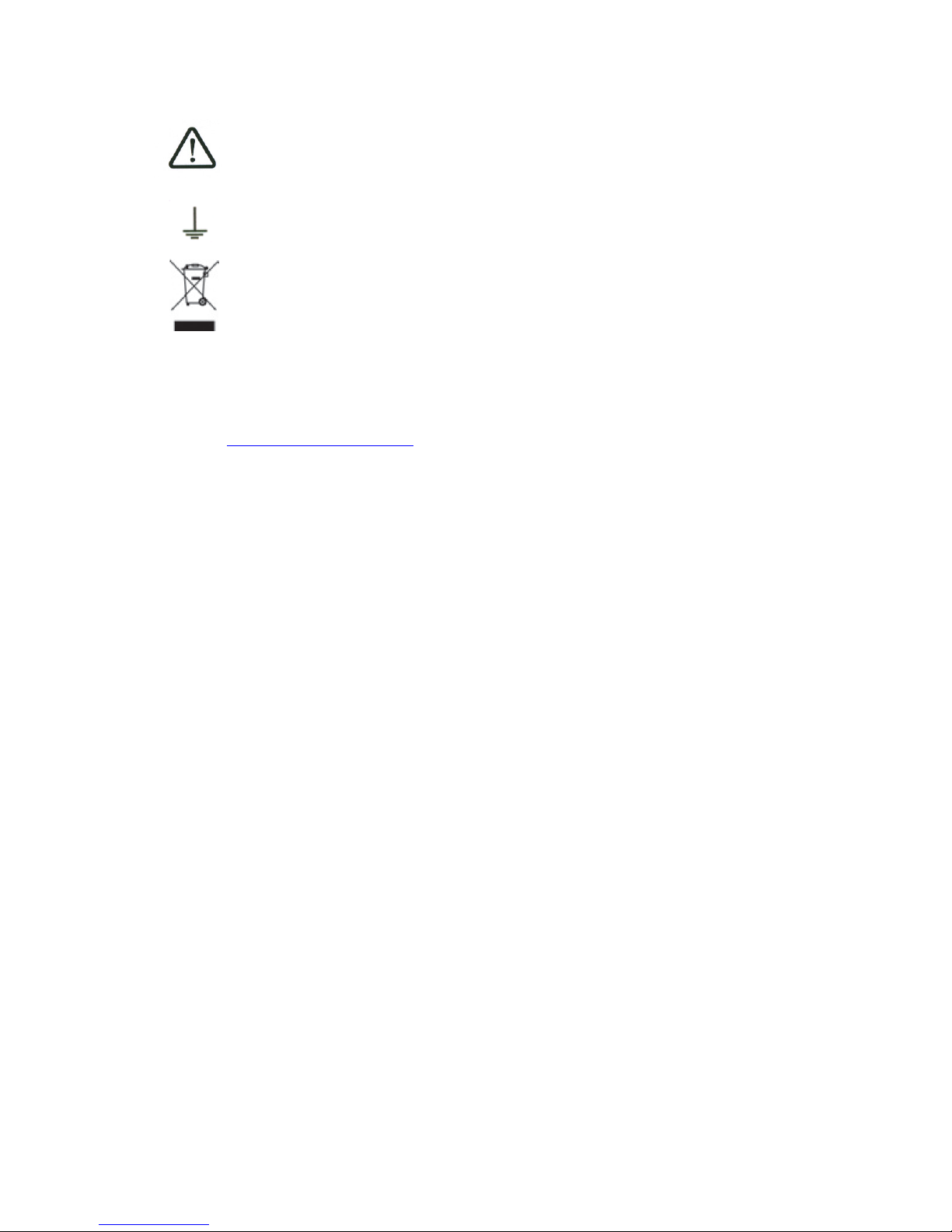
Symbols on the appliance:
Attention: Refer to the manual. Shows a risk of damage for the material connected to the instrument or to the instrument itself.
Ground: Grounded accessible parts.
Product for recycling.
1.4 Conformity and restrictions of the appliance
See chapter EC Declaration of conformity.
Page 10
– MCT059 –
p.
10
2 Quick start-up
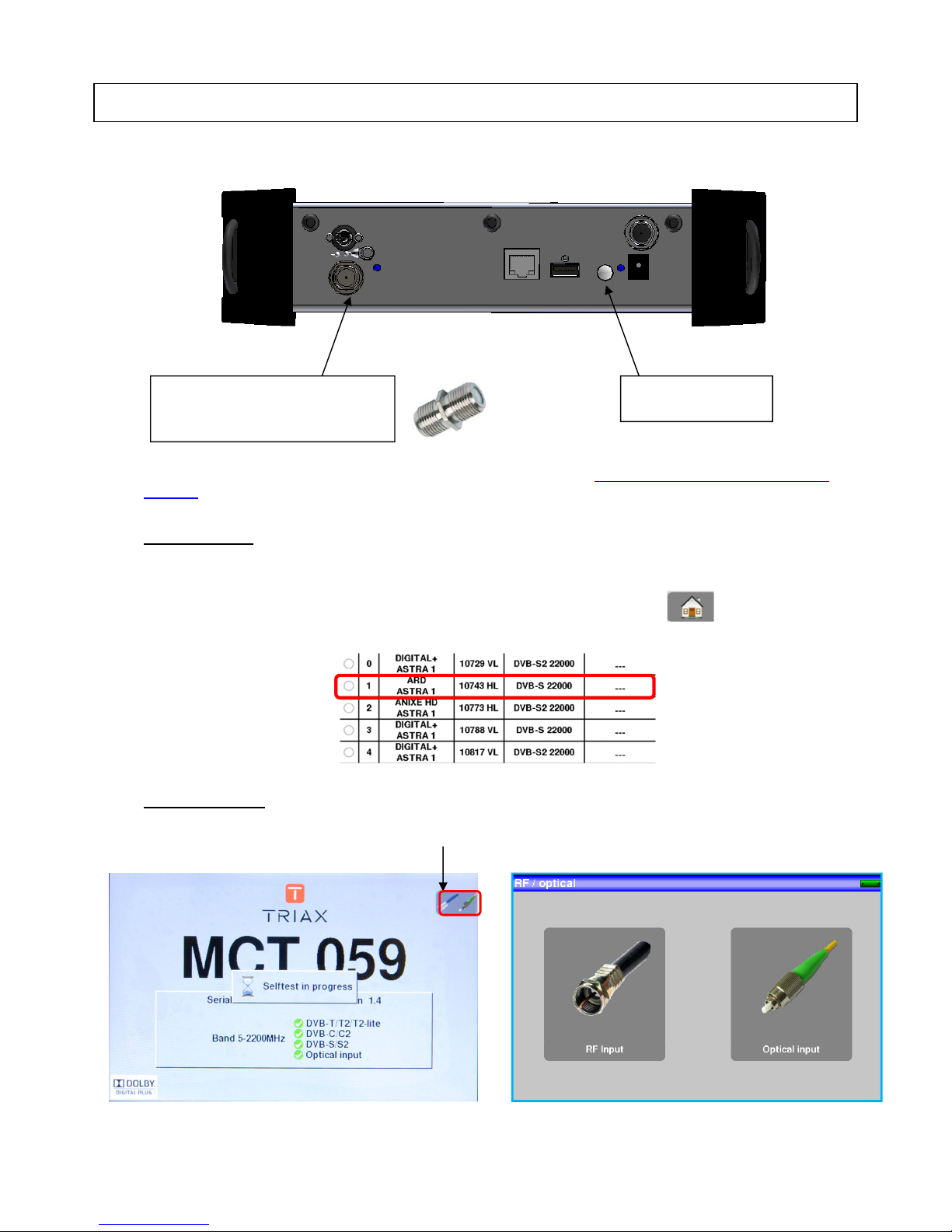
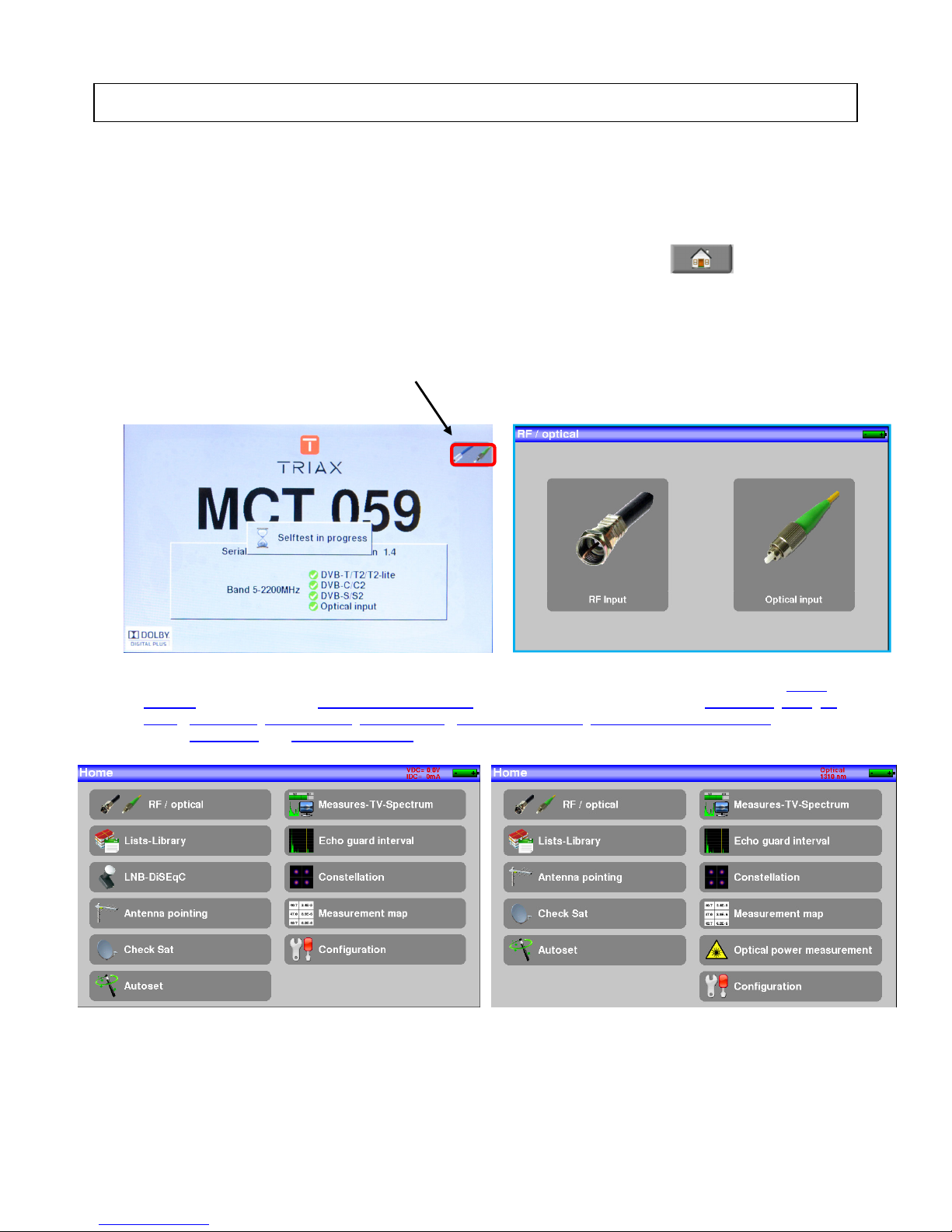
2.1 Presentation of the device
To plug the appliance for optic measurements, refer to the paragraph 19.1 Presentation of the optic meas-
urement
Important keys:
MCT059 is an appliance with a capacitive touchscreen. This requires a soft handling. No glove and no stylus
should be used, so that the triggering should be taken into account.
You will recognize the « keys » by their dark grey color (example: the home key: )
You may also access tables by pressing lines (on white or yellow)
Welcoming page:
button ON/OFF
RF connector for use with the
F/F adaptor provided with the
appliance.
Gives you access to the using mode (RF or optic)
Page 11
– MCT059 –
p.
11
Attention : To exit a window like in this example below, press the key:
2.2 Signal spotting
The MCT059 appliance tracks very quickly RF or optical terrestrial or satellite signals.
In the following chapter, we will see how to spot a RF signal on three types of installation:
• Checking of a terrestrial antenna (the installation has already been made).
• Installation of a terrestrial antenna.
• Installation of a satellite dish.
2.2.1 Scanning a terrestrial antenna in RF mode
In this case, the Autoset function allows a scan of the channels that the antenna detects.
Plug the cable of your antenna to the MCT059 appliance (WARNING: use an adequate adaptor)
The antenna shall be previously adjusted to a terrestrial emitter.
Turn on your appliance. Press RF/Optic
Press Entrée RF
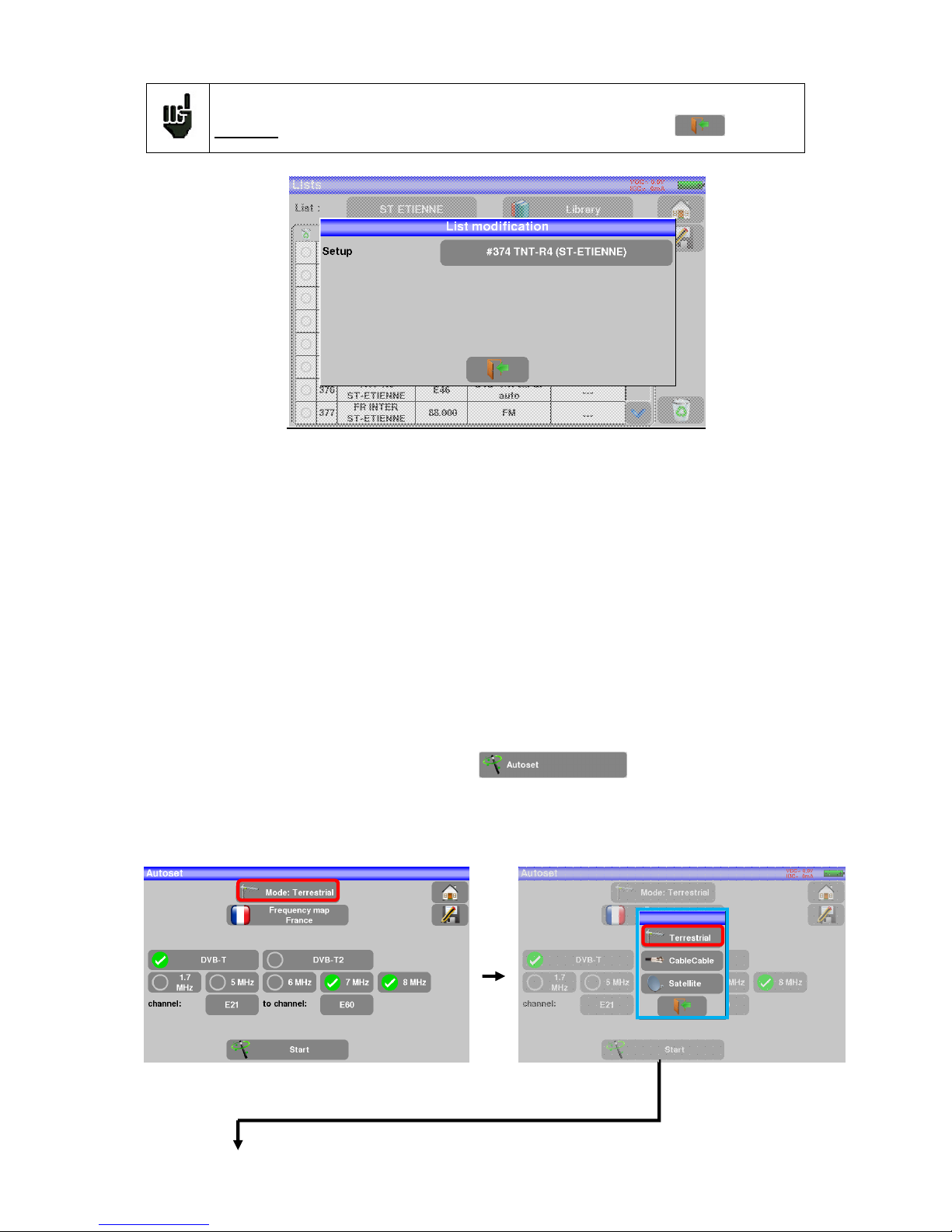
The Home page appears on screen. Press Autoset
On this page, press Mode, Terrestrial, then select DVB-T and 8MHz (as here below)
The scan should range from the E21 to the E69 channels, frequency range Europe (you may reduce the
number of channels to scan if you know the range of the emitter where the antenna points at: the scan will
be faster)
Page 12
– MCT059 –
p.
12
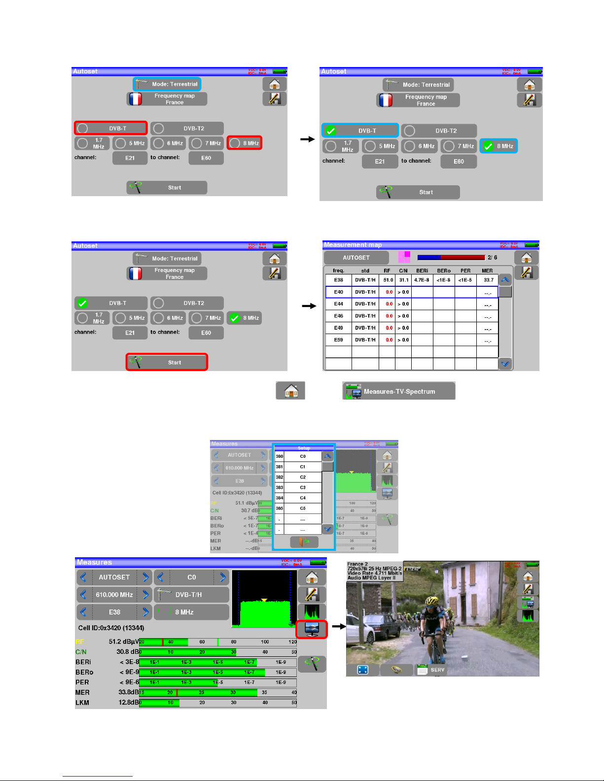
Press START. The appliance searches until the end of the scan and turns directly to the Measurement plan
mode. If channels were found, the appliance makes measurements continuously (C/N-level, then BER/MER)
on the detected channels. If no channel has been found, see the next chapter.
To finish, press the home measurement key then on , On this new page,
press Prog, select the channel that you want to display.
Check the level, the BER/MER, the TV detection and the spectrum of the signal on this page…
Page 13
– MCT059 –
p.
13
2.2.2 Installation of a terrestrial antenna
You have two methods to install a terrestrial antenna:
• Use of the spectrum
• Use of the satellite dish
2.2.2.1 Use of the spectrum
Plug the cable of your antenna to the MCT059 (take care to use an adequate adaptor)
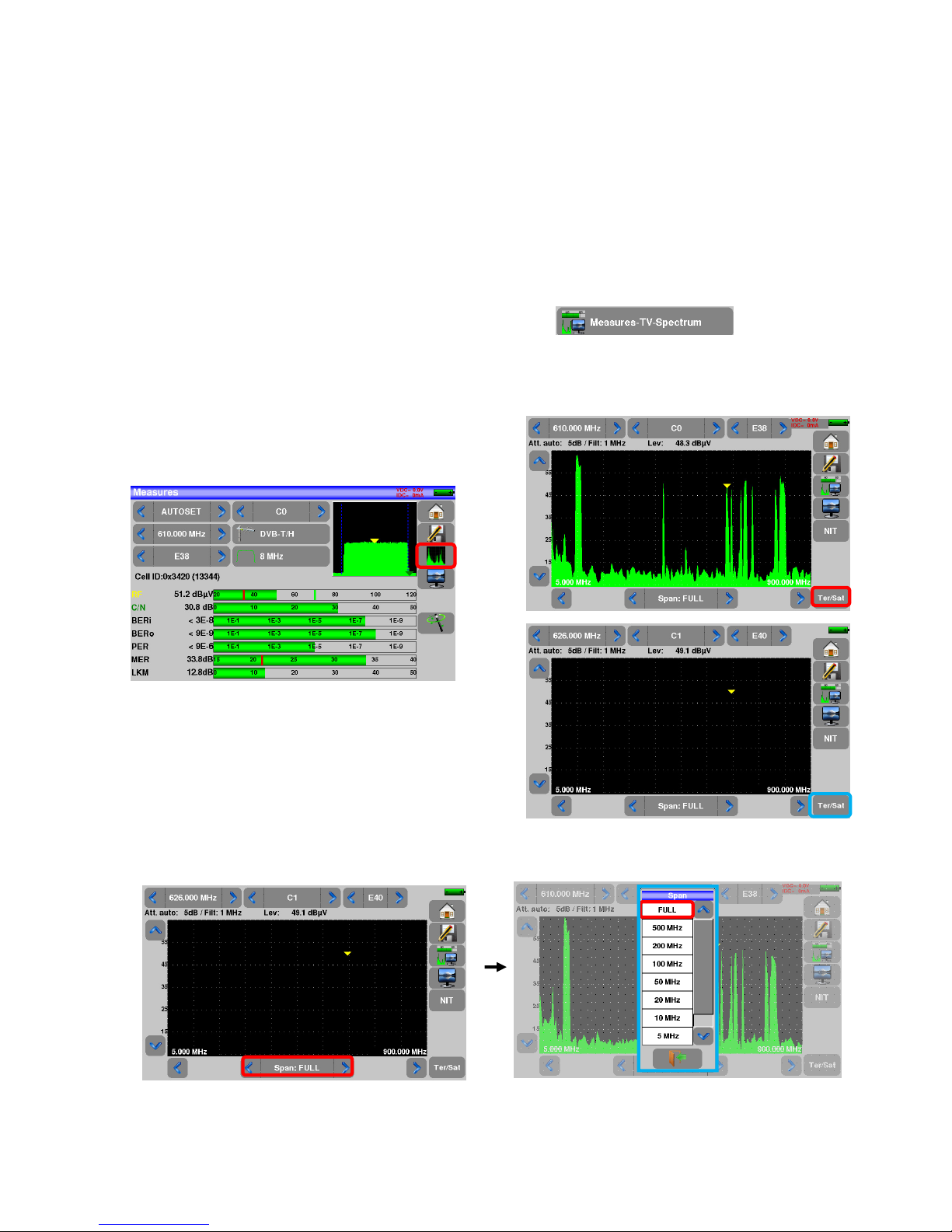
Turn your appliance on. Press the Measures-TV-Spectrum key
Press the Spectrum zone, access to terrestrial mode if needed
Access to full SPAN mode
Page 14
– MCT059 –
p.
14
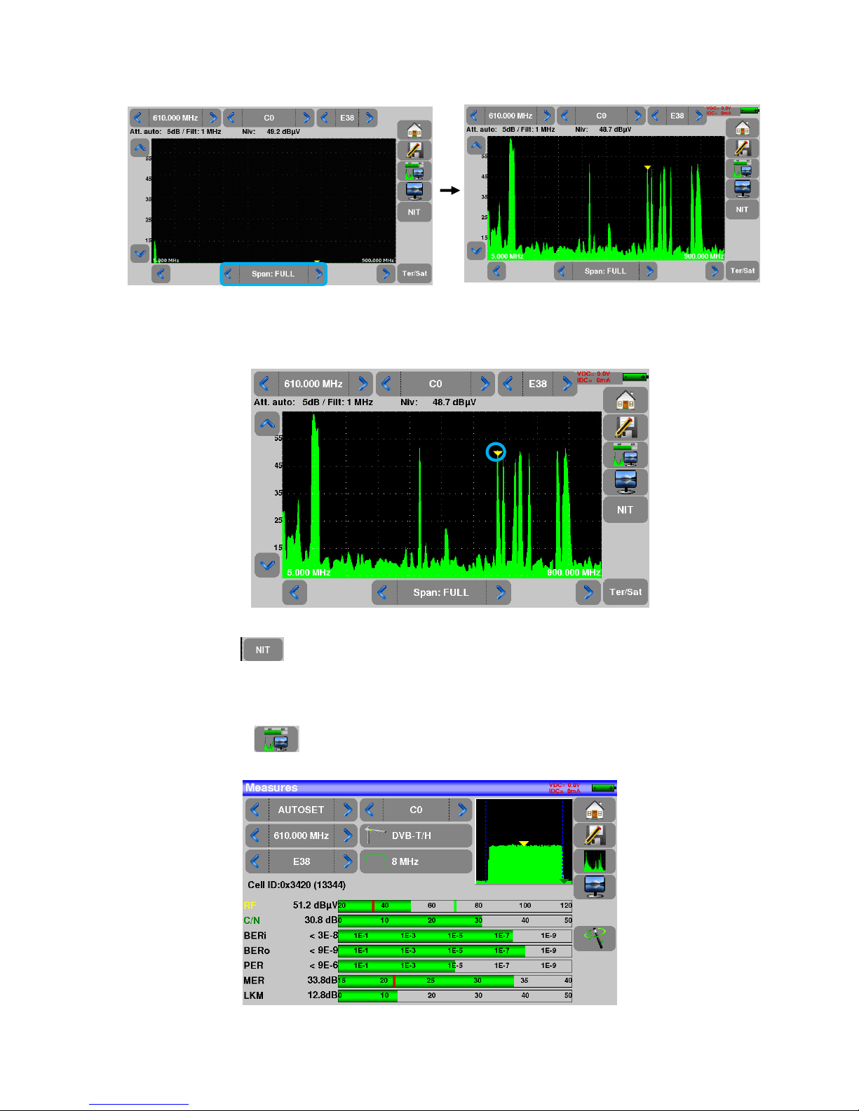
Adjust the antenna to get the most powerful signal possible
Press directly the signal you want in the spectrum (the cursor moves to where you press)
Press the NIT key , the device find automatically all the parameters of the signal.
Once the search ended, the device display the “Network Name” and the “Network ID”.
Press the Measures-TV-Spectrum key. You can now display the level, the BER/MER of the signal selected
on the same page…
Page 15
– MCT059 –
p.
15
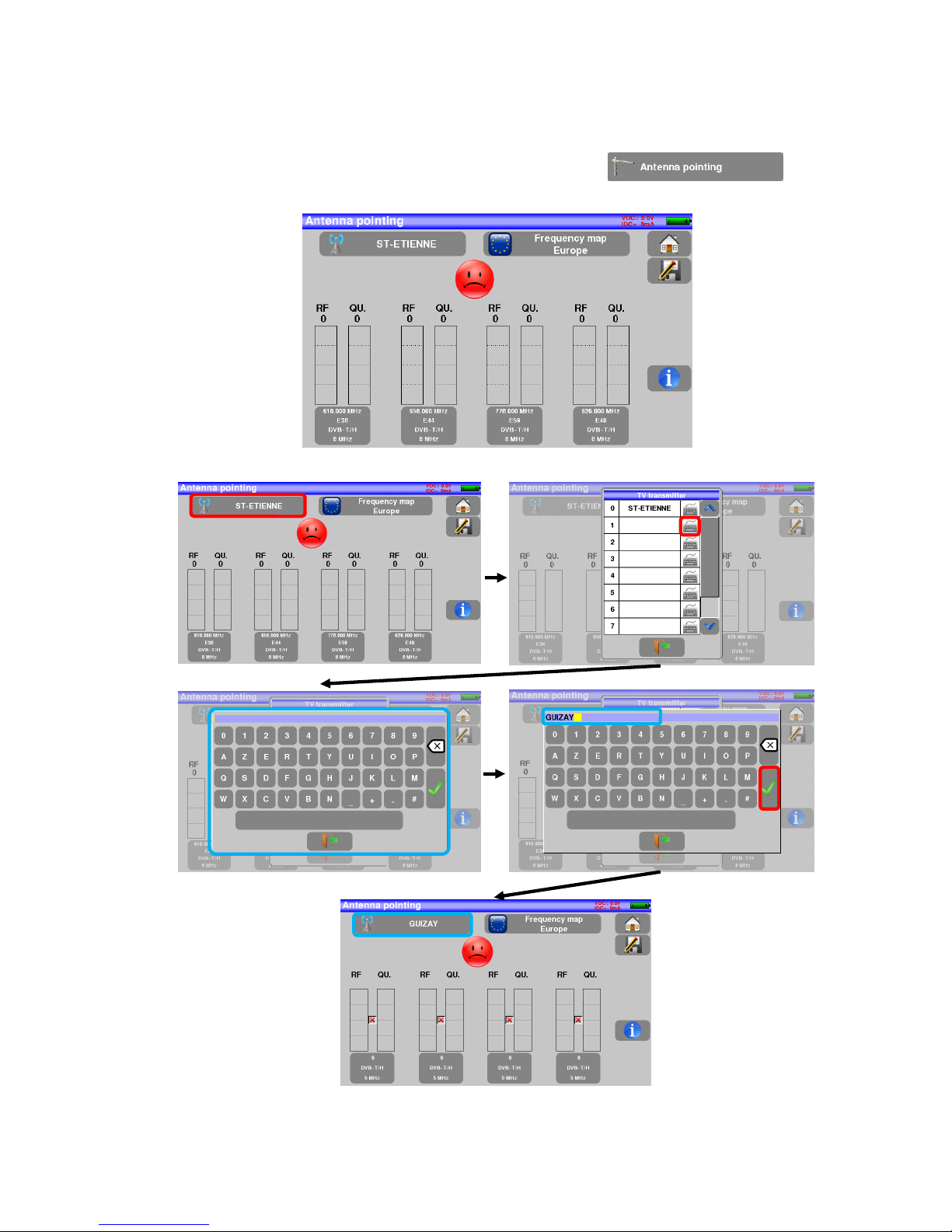
2.2.2.2 Use of the Antenna pointing
The appliance gets an “Antenna pointing” mode in order to align quickly and easily your terrestrial antenna.
To access to the “Antenna pointing” mode from the HOME page, press
The following page appears:
Set your emitter name:
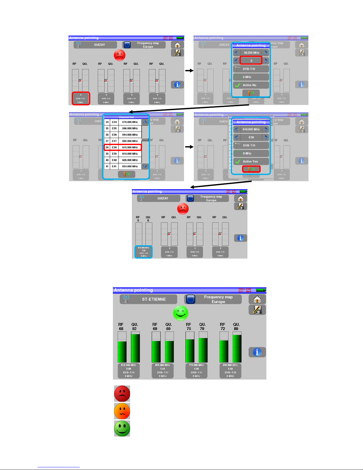
Enter 4 frequencies of the emitter you want to check.
Page 16
– MCT059 –
p.
16
Slowly orientate the antenna until hearing the locking melody and getting the best quality
No transmitter found, bad reception quality → red smiley
Average reception quality (< 50%) → orange smiley
Good reception quality (> 50%) → green smiley
Page 17
– MCT059 –
p.
17
2.2.3 Installation of a satellite dish
Connect the satellite dish to the appliance.
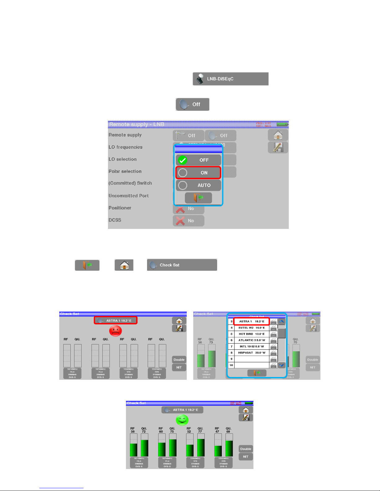
Activate the remote power supply
To access to the Remote power supply page, press
To switch on the remote power supply, press then select ON in the page to launch the remote
power supply:
A green check appears in front of what you validated
Press then and access the Check Sat mode.
(the appliance already includes a list of satellites).
Select a satellite like in the example below (here Astra1):
Page 18
– MCT059 –
p.
18
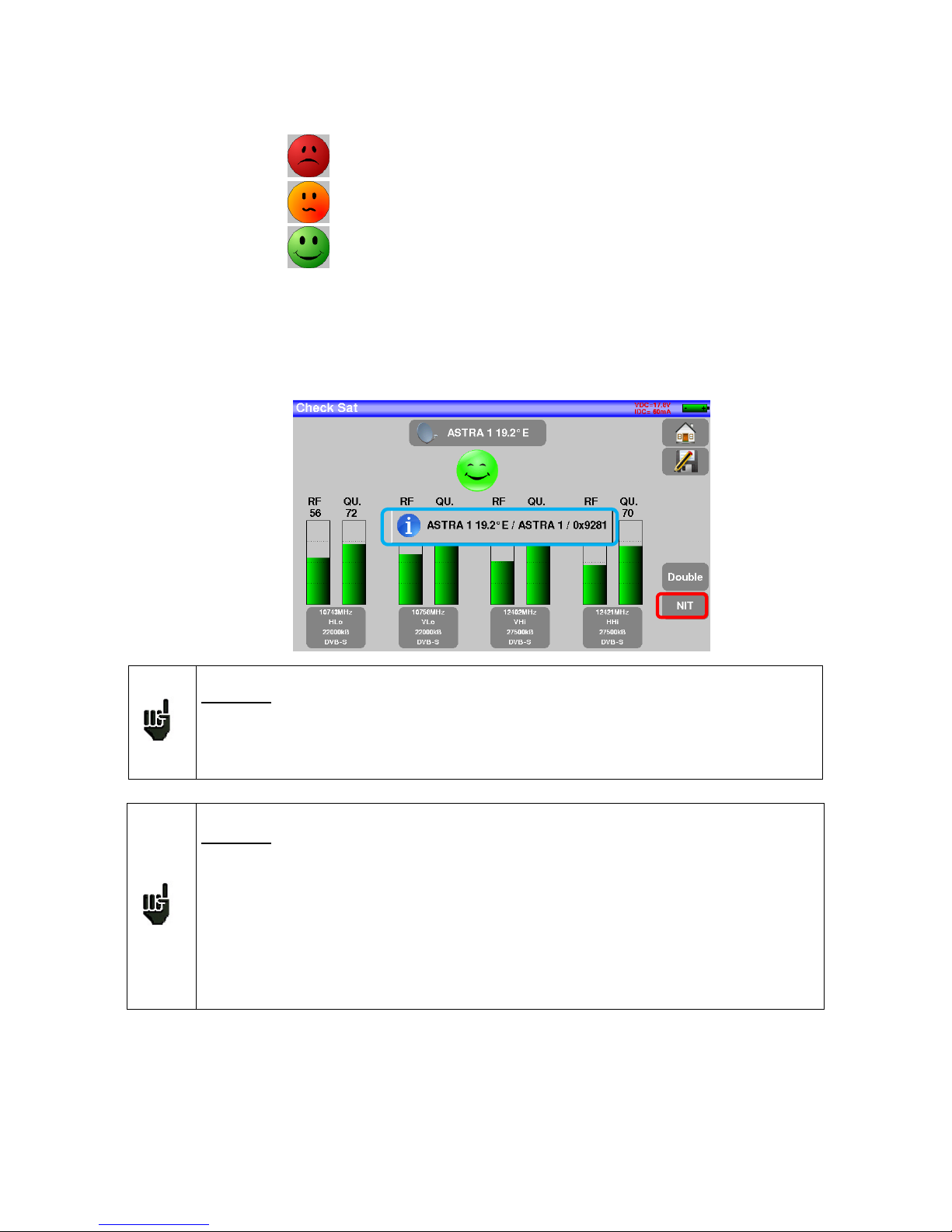
Slowly orientate the satellite dish until hearing the locking melody and getting the best quality
No found transponder → red smiley
Average reception quality (< 50%) → orange smiley
Good reception quality (> 50%) → green smiley
Reminder: transponder = satellite channel
To check if the aimed satellite is the right one: press the NIT key
The appliance searches the MPEG NIT table on one of the 4 transponders and displays the name of the
satellite:
Attention:
To identify a satellite, you must be locked on all 4 transponders. (Quality > 0)
However, some transponders are regularly modified. See the frequency range of the
satellite when a transponder does not seem to work.
Some switches or LNB work only with DiSEqC commands. In this case, position the
band (OL) and the polarization on DiSEqC at the Configuration page LNB-DiSEqC.
(Attention: the Check Sat is slower when using the DiSEqC command).
Attention: The displayed name depends on the content of the MPEG NIT table.
Some distributors provide no (or poor) such table.
The displayed information may be wrong.
Page 19

– MCT059 –
p.
19
3 Presentation
3.1 General
-The MCT059 field measurer is a handy appliance designed to qualify and maintain all RF or optical installations RF for broadcasting and receiving analogical and terrestrial digital, satellite or cable network television
channels.
-The band ranges between 5 MHz and 2200 MHz; this allows accurate measurements on all analogical television standards, FM carrier waves and the various digital standards DVB-C/C2, DVB-T/T2/T2Lite, DVB-S/S2
and DSS.
-He does Level measurements in average, peak and power according to the selected standard
-Optical power measurements are made on the 3 bands
-Conversion of an optical signal (optical head, FTH-type cable) into a RF signal RF within the band of the field
measurer
-In Measurement Plan mode, they scan up to 50 setups at the same time and compare them to decision
levels (min / max).
- Equipped with an efficient Bit Error Rate measurement (various BER, MER), they allow the full validation of
digital transmissions DVB-T/T2/T2Lite, DVB-C/C2, DVB-S/S2 and DSS.
- Providing a Constellation diagram for digital standards, the detection and display of Echoes and pre-ech-
oes permit to complete this analysis.
- You can display the digital terrestrial or satellite TV (free programs) under SD or HD.
- You can hear digital sound through integrated loudspeakers.
-Designed for use on field, it is compact (less than 2 kg battery included), autonomous (battery pack and quick
charger), equipped with a LCD 7’’ touchscreen (capacitive).
- The high memory content allows the storage of many configurations, measurements and spectrum curves.
-The appliance fully remote-controlled through USB and ETHERNET connections via a computer.
Page 20
– MCT059 –
p.
20
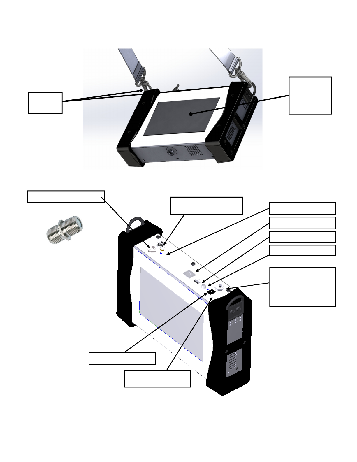
3.2 Description of the appliance
Fastening
for straps
7’’ capacitive
touchscreen
high resolution
ON/OFF switch
RF socket with F/F adapter
Remote supply light
USB A socket
Ethernet socket
External power socket
15 V 5 A max
Charging indicator light
Optical FC APC input
with protective plug
RF F output of the optical option to link to the
RF F input of the appliance via the provided
angled F/F cable
Page 21
– MCT059 –
p.
21
4 Power-up
All the material is checked before shipment and delivered in an adapted packaging. There is no particular
unpacking instruction.
The appliance is equipped with a Lithium-Ion (Li-ion) battery.
However, if the appliance has remained idle more than one month long, check its charge state and reload
if required.
4.1 Battery
Attention: Any intervention on the battery requires the disassembly of the appliance and
should be made by a TRIAX technician.
Use only batteries provided by TRIAX.
Security advice:
Do not throw into the fire or heat up the battery pack
Do not shunt the parts of the battery: risk of explosion!
Do not drill
Do not disassemble the battery pack
Do not reverse the polarities of the battery
This battery pack includes a protective item that should not be damaged or removed
Protect the pack from the heat while storing
Do not damage the protective sheath of the pack
Do not store the appliance in a vehicle under sunlight
Used batteries are not for domestic waste; lithium batteries should be recycled.
The battery has a 200-charge-discharge cycle life or 2 years.
Advice to extend the life of your battery:
Avoid deep discharges
Do not store the batteries too long without using them
Store the battery around 40% loading
Do not fully charge or fully discharge the battery before storage.
When the battery is almost fully discharged, the appliance will warn “Low battery”, and then will shut
off after a few minutes.
4.2 Battery charge
To charge the battery inside the appliance:
• Connect the external power supply provided through the jack plug of the appliance (above)
• Connect the power supply on the mains
• The internal charger starts loading the battery; the green lamp lights up.
Page 22
– MCT059 –
p.
22
Charge the device only when the device is off.
Charge the device only with the provided power supply block.
The battery is 80%-loaded after 1 hour 50 minutes. The total charge is reached after 2 hours 30 minutes.
The autonomy is defined in terrestrial mode with the lighting of the screen decreased, without remote supply, interfaces not connected and sound at 10%
4.3 External power supply
The appliance works under 15V (1 A) power supply. The power supply block provided is an external
power supply too. Only use the power supply block provided with the appliance. Use of another mains
block could damage your appliance and would not valid the guarantee.
4.4 Turning the appliance on and off
Press the button on the right side of the appliance:
The entry page appears on screen.
The message “Autotest: running” is shortly displayed, and then disappears.
Pressing this button turns the appliance off.
The ON/OFF button lights up when the appliance is working.
Pressing the ON/OFF button for a long time forces the shut-off of the appliance; pro-
ceed this way only in case of necessity.
Page 23
– MCT059 –
p.
23
5 Man-machine interface
5.1 Content of the screen
MCT059 is an appliance with a capacitive touchscreen. No glove should be used. If you don’t want to damage your screen, do not use any stylus or object.
You can recognize the« keys » by their dark grey frame, example the Home key:
You can also select lines of tables.
The MCT059 can work in RF or optical mode. You can switch from one mode to the other at start-up and
from the homepage:
The Home page allows you to navigate among all functions of the appliance. You will find there the LNB –
DiSEqC (in RF mode) and Measures-TV-Spectrum functions. But you will also find the AUTOSET, Lists-,Library , Check Sat, Configuration ,Constellation , Echo guard interval, optical power measurement (in optical
mode) RF/Optical and Measurement map keys.
Gives you access to the using mode (RF or optical)
RF mode
OPTI
CAL mode
Page 24
– MCT059 –
p.
24
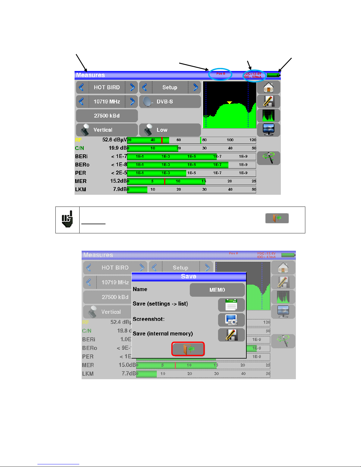
On all pages is displayed the following information:
Attention: To exit a window like this one below, you have to press the key
Indication of
the state of
the battery
Page
title
Indication of the position
of the
switch or of the SatCR (position
of the slot)
Display of the Tension and
Current values for the selected
remote powering or wavelength
Page 25
– MCT059 –
p.
25
To navigate through a table inside a page or a window, a vertical slide appears with arrows to move up and
down the table.
To move faster, you can slide a cursor with your fingers.
5.2 Changing name or value
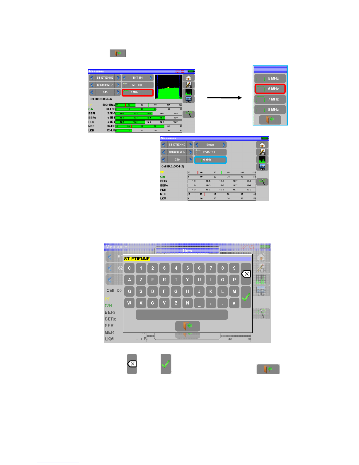
5.2.1 Changing inside a table
You can select a setup in the table. In this case, you can validate a setup by pressing the line you want to
display.
In this example, you change from the TNT-R1 setup to the TNT-R4 in the Measure page:
Cursor to navigate up
or down
Move up through
the table
Move down
through the table
Page 26
– MCT059 –
p.
26
5.2.2 Change with selection
When pressing a key, you may have a window with multiple choices. You only have to press the value you
want to validate it, the key allows you to cancel and exit this window, like in the example below:
In this example, the bandwidth changes from 8 to 6 MHz:
5.2.3 Change with virtual keyboard
If you want to enter a name of a number, a window appears with a numeric keypad and a virtual AZERTY
keypad:
In this keyboard appear keys to erase, to valid the selected value and the key to cancel
and exit from this window.
Page 27
– MCT059 –
p.
27
5.3 Lists of measurements and setup library
In order to make easier the recall of data on field, the appliance uses 20 measurement lists of each 50 lines
and 1000 setups.
A setup corresponds to a terrestrial, cable or satellite emission.
A list of measurements corresponds to a particular installation: presence of several satellite dishes, of various switches…
The same setup may be used in several measurement lists.
The same installation may use two satellite dishes
ASTRA 19.2 in DiSEqC position A
HOT BIRD 13 in DiSEqC position B
Another one may use three satellite dishes
ATLANTIC BIRD 3 in DiSEqC position A
ASTRA 1 in DiSEqC position B
HOT BIRD in DiSEqC position C
The same setup may be used several times in the same measurement list.
ZDF SatCR slot 0
ZDF SatCR slot 1
ZDF SatCR slot 2
ZDF SatCR slot 3…
If a parameter of a setup changes, for example a modification of rate or change from DVB-S to DVB-S2, only
the setup inside the library should be updated.
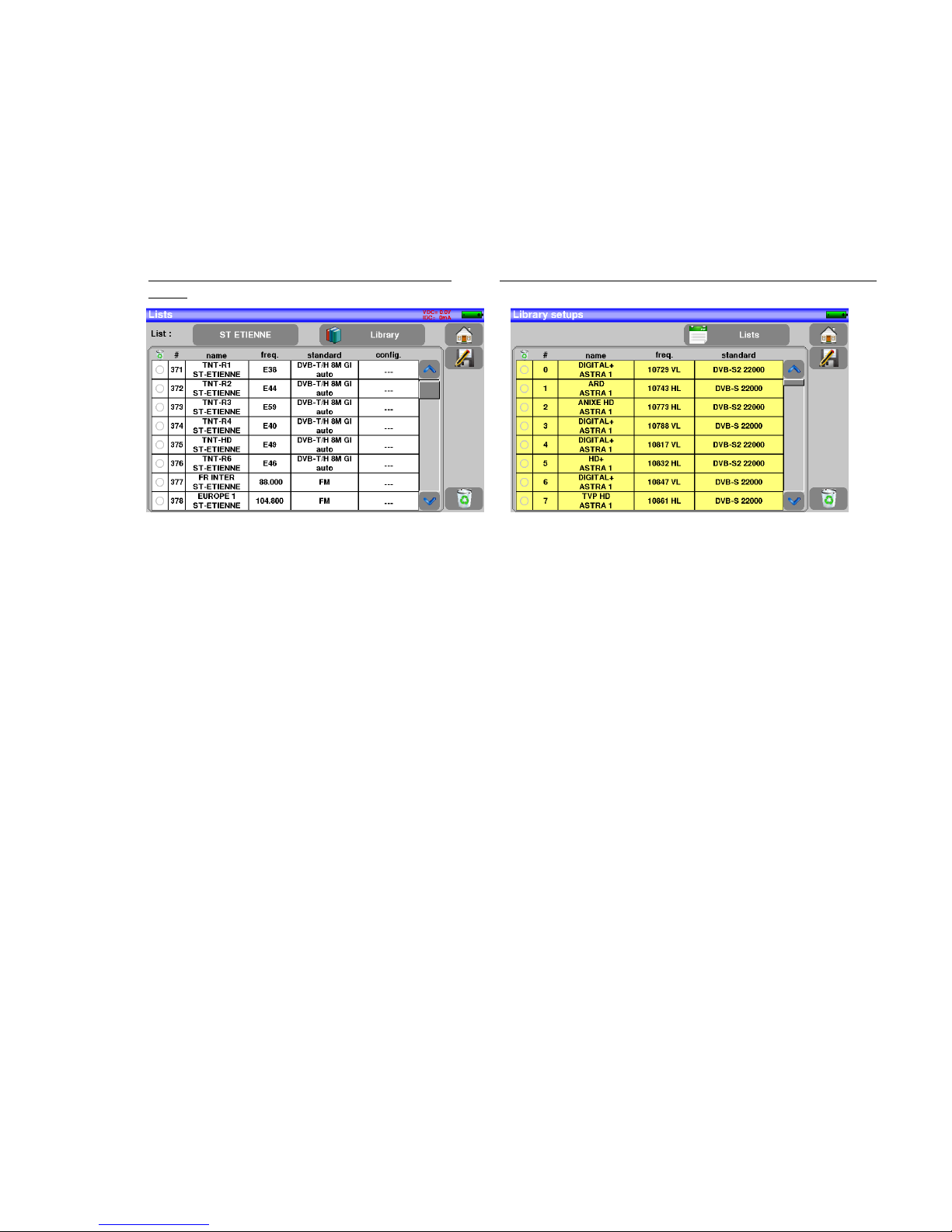
Example of list (the background of the table is
white)
Example of library (the background of the table is yellow)
Page 28

– MCT059 –
p.
28
A list of measurements is made of:
• a list name in 10 characters
• the lowest frequency of the LNB (OL1)
• the highest frequency of the LNB (OL2)
• the selection mode low band / high band of the LNB
• the selection mode of the polarization
• the presence of the position number of the positioner (motorized satellite dish)
• 50 lines including each:
• a setup number corresponding to the setup list
• the presence and the functioning mode of the switch, committed type
• the position of the switch, committed type
• the presence and the functioning mode of the switch, uncommitted type
• the position of the switch, uncommitted type
• the presence of SatCR equipment
• the SatCR slot number
• the position of the SatCR switch
A few of these parameters are specific to the waveband of the satellite and have no influence in terrestrial
and cable modes.
A setup is made of:
• a setup name in 8 characters
• a place name in 10 characters
• a frequency
• a channel number in terrestrial or cable mode
• a frequency map in terrestrial or cable mode
• a vertical or horizontal polarization in satellite mode
• a low or high LNB band in satellite mode
• a standard
• an analogical mono stereo or NICAM mode in terrestrial or cable mode
• a constellation type 64QAM 256QAM under DVB-C
• a bandwidth 5, 6, 7 or 8 MHz under DVB-T and DVB-T2
• a symbol rate under DVB-C, DVB-S, DVB-S2 or DSS
According to the terrestrial, cable or satellite band mode and to the standard, some parameters have no influence.
The place name may distinguish two distinct emitters, example TF1 Fourvière and TF1 Chambéry.
Frequency and channel number are equivalent: a valid channel number has priority over a frequency.
The frequency map parameter associated with the setup allows frontiersmen to keep on using channel numbers.
Selecting a list in the Lists page automatically recalls all information associated with this
list.
Selecting a Setup on a measurement page automatically recalls all information associated
with this setup.
Page 29
– MCT059 –
p.
29
6 AUTOSET mode
Attention: The Autoset channel research is only possible when at least one list is empty
with enough place in the library
This mode allows an automatic research of setups and to provide information about the current place.
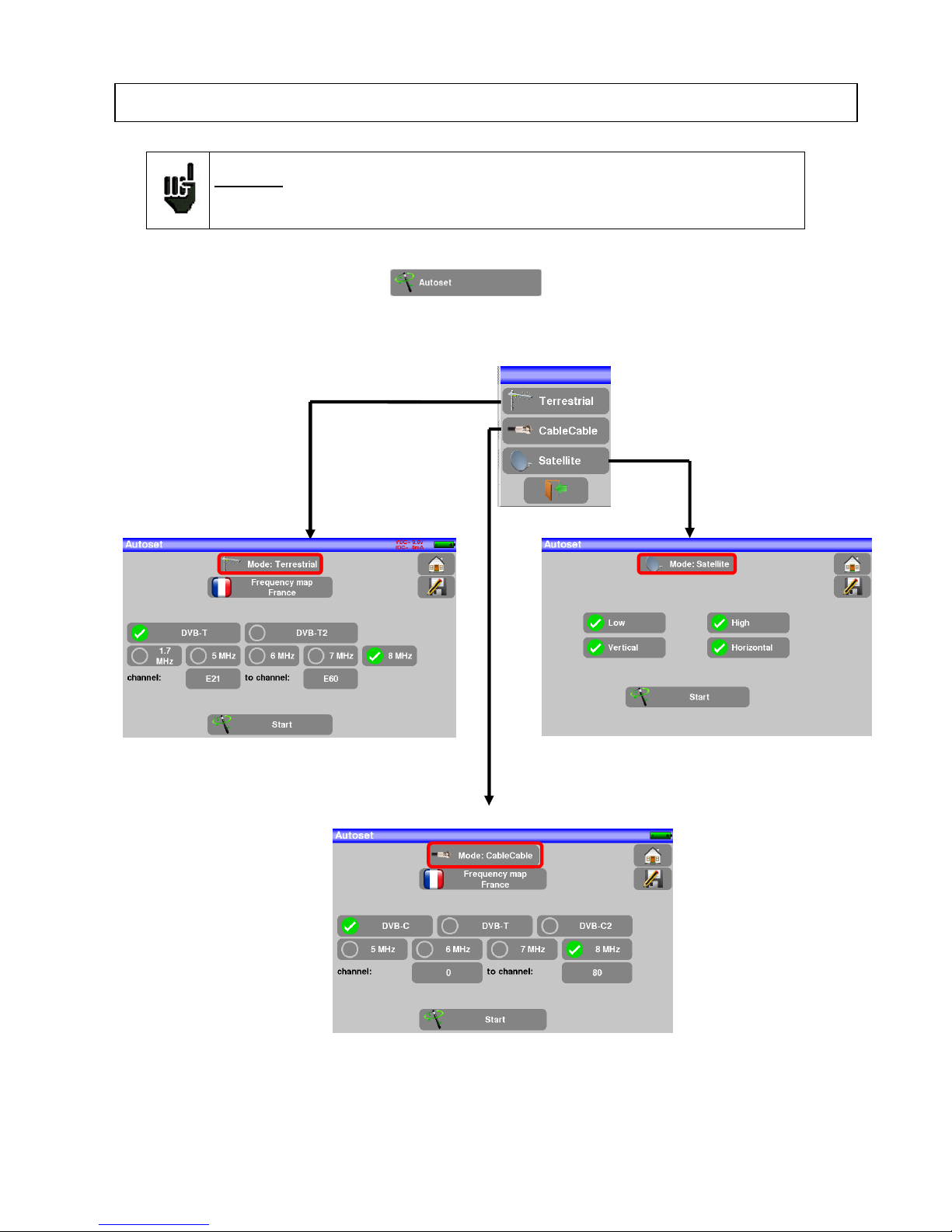
You can access it through the key on page Home.
The displayed lines on this page depend on the selected Frequency band. The key before the Mode line
allows you to select between terrestrial, cable or satellite mode:
Terrestrial Mode Satellite Mode
Cable Mode
Once the mode selected, the keys of the various parameters activate or deactivate each option.
Page 30
– MCT059 –
p.
30
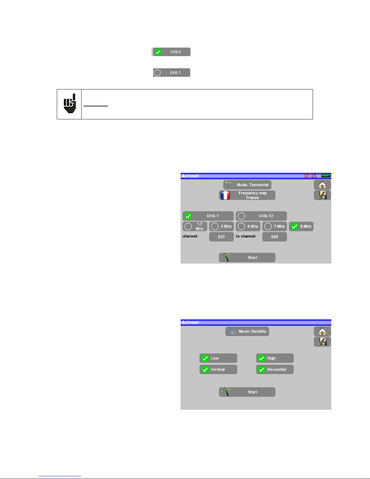
A green check shows that the parameter is included in the research. If there is no green check, the parameter will
not be taken into account for the research.
Active research parameter
Inactive research parameter
Attention: The more you select options, the longer is the research.
6.1 Terrestrial mode
This mode allows automatic research on the terrestrial frequency band.
The table allows the selection of:
• Standards
• Channel widths
• The channel range of the research
(i.e. 21 to 60).
The goal is to make researches
shorter by defining at best the settings (example: in France, no DVBT2, band width DDT 8MHz first
channel 21, last channel 60)
6.2 Satellite mode
This mode allows automatic research on the satellite frequency band.
The table allows the selection of:
• LNB bands
• LNB polarizations.
The goal is to make researches shorter again
Page 31

– MCT059 –
p.
31
6.3 Cable Mode
This mode allows automatic research on the cable frequency band.
The table allows the selection of:
• Standards
• Channel widths
• The search range of channels
6.4 «START » menu key
No matter which mode is selected, press the “START” key when the table is filled to launch the research.
Pressing “Stop” will abort the research.
When the research is done or if the user aborted it, the appliance turns automatically to the Measure-
ment map function.
Page 32

– MCT059 –
p.
32
Any detected channel will be registered into the first empty list (automatically renamed AUTOSET) and
into the fist available setups of the library, starting from the end of the table.
The new list is created in the first
available list
The default name of the new list is
AUTOSET
New found channels are added one
by one into the new list
New found channels are added one
by one into the first available setups
of the library, starting from the end
of the table
Page 33

– MCT059 –
p.
33
7 Measurement lists
7.1 The list page
In this page, you can select the list where you will work on measurements.
Pressing the Lists-Library key gives you access to the LISTS function:
Lists are ranked from 0 to 19. To select the one you want, press the following key. Lists are displayed. Press
the one you want:
In this example, we selected ST ETIENNE.
Page 34

– MCT059 –
p.
34
7.2 Modification of a list
To change the name of the list of ST ETIENNE, you must push on its name, then on the symbol of the keypad. A virtual keypad shows up. Type the new name.
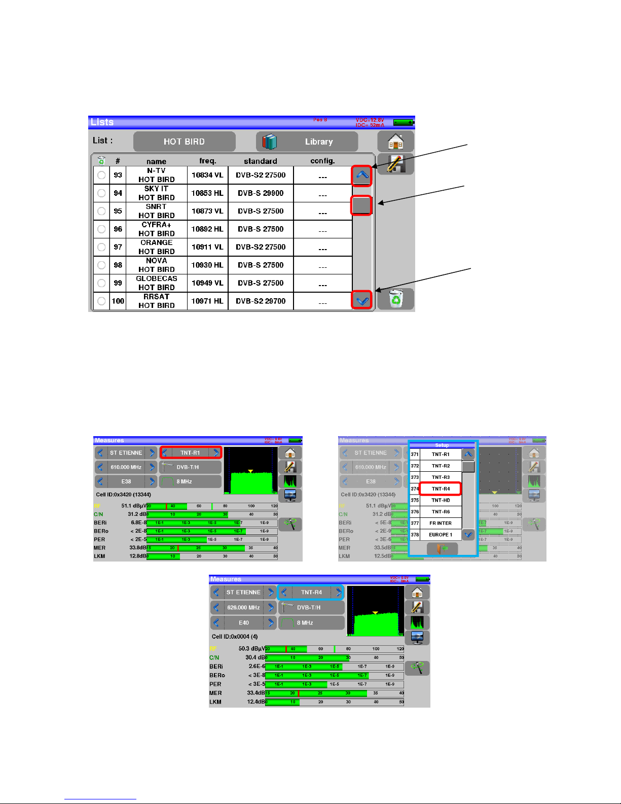
To add a setup to the list, select the line. A window shows up:
By pressing the key before Setup, you disclose the available setups from the library (you cannot create a
setup from a list; to create a setup, see Setup creation or modification in the library):
Scroll the list up or down to find the setup you want to add to your list. Press the line you want:
Attention: A list may contain a Satellite and a Terrestrial setup.
Attention: If the line contains a setup, it shall be erased. To cancel, press:
Page 35

– MCT059 –
p.
35
The setup is now in the list:
You may erase the setup from the list by pressing the check to the left of the setup or to the setups you have
to delete. Then click the basket and select the deletion of the selected setup:
Page 36

– MCT059 –
p.
36
You can also delete the totality of a list by pressing directly on the basket then by selecting
.
In a satellite setup, you can change the switch, the Uncommitted Port and the DCSS by activating any of
these keys (this change will affect only the setup in this list, not in the library):
Page 37

– MCT059 –
p.
37
8 Setup library
8.1 The library page
Pressing the Lists-Library key gives you access to the LISTS function. From this
page, you have access to the Library by pressing :
8.2 Creation or modification of setups in the library
To create or change a setup in the library, you have to select a line in the table. A window pops up:
Attention: If the line contains a setup, it will be erased. To cancel, press:
Page 38

– MCT059 –
p.
38
You may erase the setup from the list by pressing the check to the left of the setup or to the setups you have
to delete. Then click the basket and select the deletion of the selected setup:
From this window, you can create a terrestrial, satellite KU, L or C setup.
To proceed, see chapter 5
Man-machine interfaces
Terrestrial setup:
Under standard DVB-T/H DVB-T2
Under standard DVB-C / DVB-C2
In terrestrial analogical standard (L, BG, DK, I and MN)
To enter the frequency band you
want for the setup
To enter the Emitter/Satellite name
you want for the
setup
To enter the name you
want for the setup
To enter the frequency
you want for the setup
To enter the
channel you
want for the
setup
To enter the standard
you want for the setup
(DVB-T/H in this case)
To enter the symbol rate
you want for the setup
To enter the type of audio
configuration you want for
the setup (mono, stereo or
NICAM)
Page 39

– MCT059 –
p.
39
Setup Satellite KU, L or C:
Ku L or C corresponds to the selected band
To enter the type of polarity
you want for the setup (high
or low, vertical or horizontal)
To enter the symbol rate you
want for the setup
Page 40

– MCT059 –
p.
40
9 Check Sat
Press to access the Check Sat mode.
The appliance has 32 possible orbital positions for satellites. It is provided with near of 10 satellites registered.
4 transponders are appended to each satellite.
You can select the satellite by pressing « Name and position of the satellite ».
To modify a transponder, you must press the corresponding key:
Name and position
of the satellite
Global quality indi-
cation
Frequency, po-
larization,
band, level
and qualit
y
Frequency
Polarity
Symbol rate
Active or Inactive
Transponder
Standard
Page 41

– MCT059 –
p.
41
9.1 Updating satellites
You can update frequencies of the checks sat by consulting the file PDF posted on-line on the site web of
TRIAX.
You have to modify frequencies, following the previous paragraph and using the file updated monthly on the
web site of TRIAX.
We advise you to check and to update your frequencies every three months. We advise you to check and to
update your frequencies every three months
9.2 Check Sat function
Procedure:
1/ Connect the satellite dish to the appliance and start it up.
2/ Validate the remote power supply:
- VDC lights up.
- Check the power supply current of the LNB (IDC at the top right corner of the screen should be
between 50 and 200mA).
See chapter Remote power supply / LNB – DiSEqC
3/ On the Home page, go to the Check Sat mode.
Select the satellite to aim at in the list (example ASTRA1)
4/ Slowly orientate the satellite dish until hearing the locking melody and getting the best quality.
5/ Slightly turn the LNB to get the best quality (counter-polarization).
You will hear a melody as soon as a first transponder is detected; then, you will hear beeps. These beeps
are closer and closer as the quality increases.
Page 42

– MCT059 –
p.
42
If the appliance is not synchronized on all four transponders, the quality indication is red.
If the appliance is synchronized on all four transponders but the reception quality is average, the quality indication is orange.
Good reception quality (> 50%) → green smiley
Attention:
To identify a satellite, it must be synchronized on all
4 transponders
.
However, some transponders are regularly modified.
See the frequency map of the satellite if a transponder does not seem to work.
Some switches or LNB work only with DiSEqC commands. In this case, position the OL
and the polarization on DiSEqC in the Configuration page LNB-DiSEqC.
(Attention: the Check Sat is slower with DiSEqC commands).
Page 43

– MCT059 –
p.
43
9.3 Checking the aligned satellite
To check if you have aimed the right satellite, press the NIT key.
The appliance searches the MPEG NIT table on one of the 4 transponders and displays the name of the
satellite:
9.4 Double Check Sat
This mode allows you to orientate a double LNB by checking 4 transponders on 2 selected satellites. This
mode is identical to the simple Check Sat mode
.
To access the double Check Sat mode, you have to trigger the Double key.
Attention: The displayed name depends on the content of the MPEG NIT table.
Some distributors provide no (or poor) such table.
The displayed information may be wrong.
Sat. A
Sat. B
To return to the
simple mode
Page 44

– MCT059 –
p.
44
9.4.1 Recall
Azimuth
Position of the satellite dish on the horizontal plane with reference to the north. Measured in degrees.
Elevation
Tilt angle under which the beam from the satellite reaches your antenna. Measured in degrees using what is
specified on the stand of the satellite dish.
Polarization
Rotation required for the LNB from a vertical line. Measured in degrees.
Page 45

– MCT059 –
p.
45
10 TERRESTRIAL check
To access to the menu terrestrial check from Home page, press
The following page appears:
Set up your check:
Page 46

– MCT059 –
p.
46
Enter 4 frequencies or channels of the transmitter you try to check.
Once you informed the 4 transponders, slowly orientate the satellite dish until hearing the locking melody
and getting the best quality.
No found transponder → red smiley
Average reception quality (< 50%) → orange smiley
Good reception quality (> 50%) → green smiley
Page 47

– MCT059 –
p.
47
Press key permits to list the services distributed on the multiplex:
Page 48

– MCT059 –
p.
48
11 The Measures-TV-Spectrum page
TV
mode
SPECTRUM
mode full
screen
Autolock :
Automatic search of setup
Page 49

– MCT059 –
p.
49
12 Measures (MEASURES-TV-SPECTRUM)
Pressing the MEASURE zone gives access to the MEASURES function.
In this page, you can either perform measurements on a memorized program in the current list (see chapter
« Measurement list »), or change parameters manually, or use the AutoLock function
12.1 Autolock function
This function is design to lock on a digital signal (terrestrial, cable or satellite)
You just have to enter the frequency or the channel (for terrestrial), then press AutoLock, The instrument will
find automatically in few seconds the digital standard, the modulation type and all other parameters of the
signal.
Example for terrestrial, channel 38 (frequency 610MHz):
Example for satellite low vertical polarization, frequency 12109 MHz :
Page 50

– MCT059 –
p.
50
12.2 Modification of parameters
The various parameters are:
• The name of the setup (selection on the active list)
• The frequency of the emitter or transponder (and the true frequency of satellite)
• The standard and bandwidth for DVB-T/H and DVB-T2
• The corresponding channel number for terrestrial and cable mode
• The symbol rate for the satellite
• The polarization and the band for the satellite
• The audio mode for the analogical TV
12.3 Level measurements
You can measure levels at a specific frequency with a detection matching the standard.
In terrestrial band, for an user socket, the level should be:
- between 50 and 66 dBµV under FM
- between 35 and 70 dBµV under DVB-T/H, DVB-T2
- between 57 and 74 dBµV in any other case
In satellite band, for an user socket, the level should be:
- between 47 and 77 dBµV.
You can shift from terrestrial to satellite mode by:
- Changing the setup frequency
- Changing of standard
- Changing of setup (from a terrestrial to a satellite setup)
Page 51

– MCT059 –
p.
51
Example in terrestrial mode:
The appliance makes different measurements according to the current standard.
The other possible measurements are:
• Average measurement
• Peak measurement
• Power measurement.
12.4 Satellite band
The following table sums up the measurement types and the frequencies of the audio carrier waves for each
standard:
Standard Video carrier Measure
PAL FM Peak
SECAM FM Peak
NTSC FM Peak
DVB-S Digital Power
DSS Digital Power
DVB-S2 Digital Power
The best is to be the closest possible of the green bar without exceeding it.
For the MER measure, the value must be superior to the mini threshold.
Signal/noise ratio of
the signal
Signal level
Reduced spectrum of the
Span signal, ca. 10MHz
Page 52

– MCT059 –
p.
52
12.5 Terrestrial band
The appliance automatically makes level measurements on the Video carrier wave.
The following table sums up the measurement types and the frequencies of the audio carrier waves for each
standard:
Standard Video carrier Measure Sound carrier
Mono stereo NICAM
BG negative, AM peak FM FM DQPSK
5.5 MHz 5.74 MHz 5.85 MHz
DK negative, AM peak FM FM DQPSK
6.5 MHz 6.258 MHz 5.85 MHz
I positive, AM peak FM DQPSK
6.0 MHz 6.552 MHz
L positive, AM peak AM DQPSK
6.5 MHz 5.85 MHz
MN negative, AM peak FM FM
4.5 MHz 4.72 MHz
DVB-C digital power
DVB-T/H digital power
DVB-T2 digital power
DAB/DAB+ digital power
FM FM average
Carrier not modulated average
The appliance displays the level of the Video carrier wave and the C/N ratio.
12.6 Thresholds
Predefined thresholds are used to assess if the measurement is pertinent.
Standard Min Max
Terrestrial analog TV 57 74
DVB-C/C2 57 74
DVB-T/T2 35 70
DAB-DAB+ 35 70
FM, Carrier 50 66
Satellite analog TV 47 77
DVB-S, DSS 47 77
DVB-S2 47 77
Page 53

– MCT059 –
p.
53
min threshold max threshold
12.7 Digital measurements
In digital measurement mode, in addition to the RF level and to the C/N here above, the appliance also displays the various BER (Bit Error Rate), the PER (Packet Error Rate) and the MER (Modulation Error Ratio)
under DVB-T/T2/T2Lite, DVB-C/C2, DVB-S/S2 or DSS.
You also get the LKM:x.xdB (Link Margin) specification.
This expression in dB is the difference between the measured MER and the limit MER before disconnection
of the image: it’s the security available before disconnection.
“Sync ?” displayed on screen means that the signal is absent or unlocked; check its presence, the modulation parameters, the presence of remote power supply and the LNB and
DiSEqC parameters under satellite band.
The sign < before a value or error rate shows that there is no error but that 10-X bits have
been tested (i.e. <10
-8
means that 108 bits have been tested).
You can shift from terrestrial to satellite mode by:
- Changing the setup frequency
- Changing of standard
- Changing of setup (from a terrestrial to a satellite setup)
Page 54

– MCT059 –
p.
54
12.8 DVB-T/H
Display of the measures of:
• BERi: error rate before Viterbi
• BERo: error rate after Viterbi
• PER: error rate after Reed Solomon (error rate packet)
• MER: modulation error rate
• LKM: noise margin (Link Margin)
BERx: ‘bits’ error rate
Ratio between the number of false bits / number of transmitted bits during the measurement time
PER: ‘packets’ error rate
Ratio between the number of false packets / number of transmitted packets during the measurement time
Recall: Under DVB-T/H, a packet is made of 204 octets; a packet is "false" if it includes more than 8 wrong
octets (correction by Reed Solomon coding).
Display of the value of Cell ID from the diffuser and specific to the emitter.
TUNER
DEMODULATEUR
VITERBI
REED
SOLOMON
DECODAGE
MPEG
PER BERi BERo
Page 55

– MCT059 –
p.
55
12.9 DVB-T2 /T2 Lite
Display of the measures of:
• BERi: error rate before LDPC
• BERo: error rate after LDPC
• PER: error rate after BCH (lost packets)
• MER: modulation error rate
• LKM: noise margin (Link Margin)
Recall:
LDPC: Low Density Parity Check
BCH: Bose Chauhuri Houquenohem
The concatenation Viterbi + Reed Solomon of the correction of DVB-T/H has been replaced by the concatenation LDPC + BCH under DVB-T2.
Display of the values of Cell_ID from the diffuser and specific to the emitter.
TUNER
DEMODULATEUR
BCH
DECODAGE
MPEG
BERi PER
LDPC
BERo
Page 56

– MCT059 –
p.
56
12.10 DVB-C
Display of the measures of:
• BERo: error rate before Reed Solomon
• PER: error rate after Reed Solomon (error rate packet)
• MER: modulation error rate
• LKM: Noise margin (Link Margin)
BERo: error rate ‘bits’
Ratio between the number of false bits / number of transmitted bits during the measurement time
PER: error rate ‘packets’
Ratio between the number of false packets / number of transmitted packets during the measurement time
Recall: Under DVB-C, a packet is made of 204 bites; a packet is "false" if it includes more than 8 wrong octets (correction by Reed Solomon coding).
TUNER
DEMODULATEUR
REED
SOLOMON
DECODAGE
MPEG
BERo
PER
Page 57

– MCT059 –
p.
57
12.11 DVB-C2
Display of the measures of:
• BERi: error rate before LDPC
• BERo: error rate after LDPC
• PER: error rate after BCH (lost packets)
• MER: modulation error rate
• LKM: noise margin (Link Margin)
Recall:
LDPC: Low Density Parity Check
BCH: Bose Chauhuri Houquenohem
• Active PLP and Data slice
TUNER
DEMODULATEUR
BCH
DECODAGE
MPEG
BERi PER
LDPC
BERo
Page 58

– MCT059 –
p.
58
12.12 DVB-S et DSS
Display of the measures of:
• BERi : error rate before Viterbi
• BERo : error rate after Viterbi
• PER : error rate after Reed Solomon (error rate packet)
• MER : modulation error rate
• LKM : Noise margin (Link Margin)
BERx : error rate ‘bits’
Ratio between the number of false bits / number of transmitted bits during the measurement time
PER : error rate ‘packets’
Ratio between the number of false packets / number of transmitted packets during the measurement time
Recall: Under QPSK (DVB-S) a packet is made of 204 octets; a packet is "false" if it includes more than 8
wrong octets (correction by Reed Solomon coding). Under DSS, a packet is made of 146 octets.
TUNER
DEMODULATEUR
VITERBI
REED
SOLOMON
DECODAGE
MPEG
BERi BERo
PER
Page 59

– MCT059 –
p.
59
12.13 DVB-S2
Display of the measures of:
• BERi : error rate before LDPC
• BERo : error rate after LDPC
• PER : error rate after BCH (lost packets)
• MER : modulation error rate
• LKM : Noise margin (Link Margin)
Recall:
LDPC: Low Density Parity Check
BCH: Bose Chauhuri Houquenohem
The concatenation Viterbi + Reed Solomon of the correction of DVB-S has been replaced by the concatenation LDPC + BCH under DVB-S2.
TUNER
DEMODULATEUR
BCH
DECODAGE
MPEG
BERi PER
LDPC
BERo
Page 60

– MCT059 –
p.
60
13 Spectrum analyzer
Pressing SPECTRUM gives access to the SPECTRUM ANALYSER function. (graphical representation
frequency / amplitude of the present signals in the input of the device)
Satellite Terrestrial
2 predefined bandwidths are available: terrestrial and satellite. To swap from satellite to terrestrial, press
the key, as shown on the bottom side of the screen.
The input attenuator is automatically tuned according to the level of the signals measured.
Filters are automatically selected according to the « Span ».
The filter used is displayed on the upper left corner.
Parameters of the spectrum are:
Channel: use a channel for the spectrum
(in terrestrial mode).
Cursor: simply press the area
where you want to move or set the
cursor
Span : frequency span around the
center frequency
Reference level: can
be modified with updown arrows
List: you can select a Program (in the current list)
Frequency range: can
be changed using the
arrows
Frequency: value of the frequency where the cursor is,
user can enter a frequency
value, or increase – decrease
the frequency with <> keys
Page 61

– MCT059 –
p.
61
14 Image and Sound
Pressing the TV zone gives access to the TV function.
14.1 Digital TV
The name of the service and its main characteristics are displayed on top left of the screen.
• 720x576i: picture resolution 720 pixels / line, 576 lines, interlace
• 25 Hz: frame frequency
• MPEG-2: picture compression
• Video Rate 4.106 Mbits/s : instantaneous binary rate of the service
• Audio MPEG Layer II: sound compression
On this page, there are 3 keys at the bottom of the screen; they will be described in the next chapters
14.2 Full screen mode
Pressing the key displays the image in full screen; only remain the battery level and the intensity
+ voltage of the remote power supply:
To exit, you only have to touch the screen anywhere.
Page 62

– MCT059 –
p.
62
14.3 Audio
To set the volume, press an adjustment bar shows up:
The instrument can decode the following digital sound formats:
MPEG-1 L1/L2
AAC Advanced Audio Coding License Via Licensing
HE-AAC High Efficiency AAC License Via Licensing
Dolby Digital License Dolby®
Dolby Digital Plus License Dolby®
Made under license by Dolby laboratories.
Dolby and the double-D symbol are trademarks of Dolby Laboratories
14.4 Table of services
Pressing gives access to the list of services:
This function allows selecting the channel you want to display. You only have to press the line you want.
Page 63

– MCT059 –
p.
63
15 Remote power supply / LNB – DiSEqC
The key gives you access to the remote power supply / LNB-DiSEqC.
To start the remote power supply, press the key after Remote supply:
15.1 Terrestrial band
In terrestrial mode, you can select:
A green check shows which voltage is selected.
OFF to turn off the
remote power supply
in terrestrial measure
5V-13V-18V-24V
to send 5, 13, 18
or 24 V to the RF
according to your
requirements
Page 64

– MCT059 –
p.
64
15.2 Satellite band
15.2.1 Power ON
Setting the remote power supply to satellite:
Configuration lines:
See chapter Man-machine interface for any change.
-DCSS: Digital Channel Stacking (2
modes SATCR and SCD2 single
cable distribution)
- LO1 and LO2 Frequency:
LO frequencies low and high
band of LNB
- LO selection: band commutation
on the LNB (22 kHz, Tone Burst or
DiSEqC)
- Selection polar: polarization
commutation on the LNB (13/18V
or DiSEqC)
- Switch: switch type and position
(No, Tone Burst, 22 kHz, DiSEqC,
Pos A, B, C or D)
-Uncommitted: "Uncommitted" switch type
and position (No, DiSEqC, Pos 1 to 16)
-Positioner: presence of a positioner
(Yes / No)
ON to turn on the
remote power supply under satellite
measure
OFF
to turn off the remote power supply under satellite measure
AUTO to launch automatically the remote power supply in
satellite measure
mode even after
shutting off
Page 65

– MCT059 –
p.
65
15.2.1 Switches
2-satellite switch 4-satellite switch
* 22 kHz * DiSEqC Committed or Uncommitted
* ToneBurst (MiniDiSEqC)
*DiSEqC Committed or Uncommitted
16-satellites switch
Sat A
Sat B
Com
21
Sat A
Sat B
Sat D
Sat C
Com
Sat A
Sat B
Sat D
Sat C
Com
Sat A
Sat B
Sat D
Sat C
Com
Sat A
Sat B
Sat D
Sat C
Com
Sat A
Sat B
Sat D
Sat C
Com
2 1 4 3 14 13 16 15
6
5
8 7
10
9
12 11
Uncommitted
Sat A
Sat B
Sat D
Sat C
Com
2 1 4 3
Page 66

– MCT059 –
p.
66
* DiSEqC Committed + Uncommitted
Switch line Uncommitted line
Satellite
Position DiSEqC command Position DiSEqC command
1 Pos A Option A + Position A Pos 1 Input 1
2 Pos B Option A + Position B Pos 1 Input 1
3 Pos C Option B + Position A Pos 1 Input 1
4 Pos D Option B + Position B Pos 1 Input 1
5 Pos A Option A + Position A Pos 2 Input 2
6 Pos B Option A + Position B Pos 2 Input 2
7 Pos C Option B + Position A Pos 2 Input 2
8 Pos D Option B + Position B Pos 2 Input 2
9 Pos A Option A + Position A Pos 3 Input 3
10 Pos B Option A + Position B Pos 3 Input 3
11 Pos C Option B + Position A Pos 3 Input 3
12 Pos D Option B + Position B Pos 3 Input 3
13 Pos A Option A + Position A Pos 4 Input 4
14 Pos B Option A + Position B Pos 4 Input 4
15 Pos C Option B + Position A Pos 4 Input 4
16 Pos D Option B + Position B Pos 4 Input 4
15.2.1 Positioner
The appliance sends a DiSEqC command that triggers the rotation of a motorized satellite dish.
In this example, the position is 2 (1 to 127 pre-loaded positions in the positioner)
If the positioner is on No, it is deactivated
See chapter Man-machine interface for any change.
Page 67
– MCT059 –
p.
67
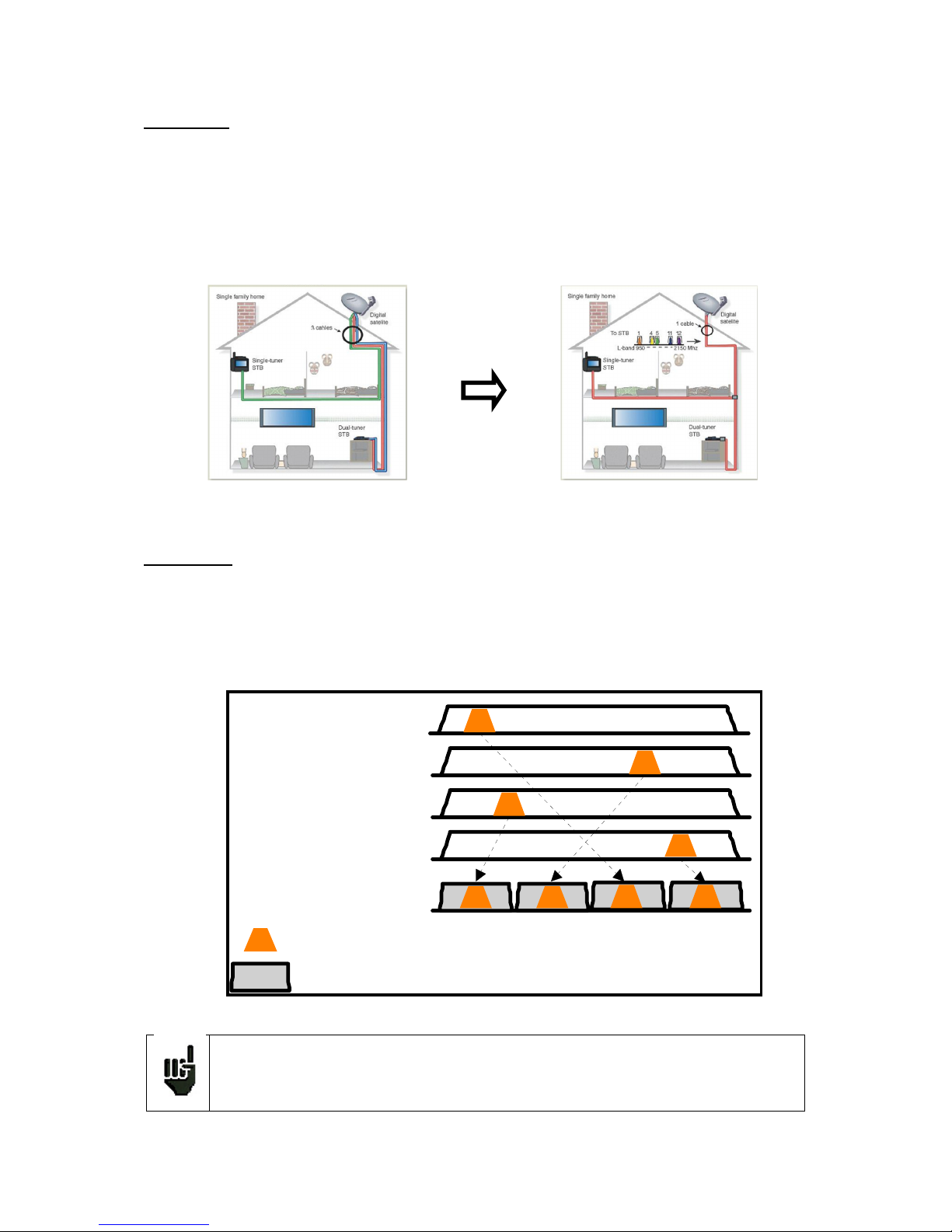
15.2.2 DCSS
Description:
DCSS Digital Channel Stacking system: signal distribution system using frequency transposition.
Used in satellite distribution for multiple or single dwelling, with several set top boxes.
To give several receptors access to the whole spectrum and all polarizations, you need one coaxial cable
per receptor and a suitable installation (multiple LNB, Quattro and multi-switches).
The DCSS system allow to feed dwellings with one or more satellites using only one coaxial cable (SCD=SIN-
GLE CABLE DISTRIBUTION).
The DCSS is an extension of the DiSEqC protocol that allows the connection of several receptors on only one
coaxial cable, no matter the band (H/L) and the polarization (H/V).
Functioning:
Each satellite receptor uses a fix frequency band (Slot or Port), whose width is (more or less) equal to the
width of the transponder.
The receptor requires a specific transponder frequency (frequency Ku) via a DiSEqC command.
Some equipment on the satellite dish (LNB or switch) moves the requested signal to the center of the selected
band (Slot). Then, the mixing equipment adds each user band (Slot) to only one output (up to 32 user bands).
The DCSS mode has priority on all other modes: selection polarization, selection
OL, switches committed and uncommitted and positionner.
Sa t A - High / Horizontal
Sa t A - High / Horizontal
Sa t A - Low / Horizontal
Sa t A - Low / Vertica l
Signal sur un seul câ ble
Tra nspondeurs
Ba n de s utilisateurs (Slot)
Tp1
Tp2
Tp3
Tp4
Slot1 Slot2 Slot3 Slot4
Page 68

– MCT059 –
p.
68
2 Modes :
SATCR : Satellite Channel Router, standard EN50494 (or SCD, Unicable, …)
Distribution of the satellite signal with only one coaxial cable to 2, 4 or 8 different receptors.
SCD2 : Single Cable Distribution v2, standard EN50607 (or SCD2, Unicable II, JESS)
Distribution of the satellite signal with only one coaxial cable to a maximum of 32 different receptors.
Using DiSEqC 2.0 bi-directional possibility to ask current online devices and speed up installation.
Mode choice: press DCSS
SATCR (EN50494) :
• SLOT x: active Slot choice
• CONFIG: access to each slot configuration
Slots list, frequencies and switch PosA / PosB
• INITIALISATIONS: 8 predefined slots
• ITALY: 4 predefined slots for Italy
• DETECT: automatic detection of slots (spectrum
detect based)
•
Page 69

– MCT059 –
p.
69
SCD2 (EN50607) :
• SLOT x: active Slot choice
• CONFIG: access to each slot configuration
Slots lists, frequencies, switches, PIN codes
• INITIALISATIONS : 32 predefined slots
• ALLOCATION : states of the 32 possible slots
• DETECT : automatic detection of slots (DISEQC2.0
based)
15.2.2.1 Influence of the DCSS on the spectrum analyzer
Landmarks of the user
band (slot)
SatCR mode and active slot
Current polarization and
band in the active slot
Frequency of the transponder visible at the
center of the active slot
Page 70

– MCT059 –
p.
70
16 Constellation
The key gives you access to the CONSTELLATION function.
These measures are available if one of these standards is running in the LEVEL MEASUREMENT page.
• DVB-T/H
• DVB-T2
• DVB-C
• DVB-C2
• DVB-S, DSS, DVB-S2
The appliance displays the Constellation of the current signal.
The information displayed on the right of the Constellation diagram is:
• current frequency
• modulation
• constellation
• symbol rate
• error rate and MER
Page 71

– MCT059 –
p.
71
17 Echo / Guard interval
Available only for DVBT/H, DVB-T2 or DVB-C2 standards.
Pressing allows you to access to Echo Guard interval measurement.
Pressing changes the horizontal scale (distance).
Horizontal scale can be set in µs, km or miles by pressing
Moving measurement arrow can be done by screen touch, or by automatic search keys
and .
The end of the guard interval is displayed with a yellow line.
Reminder:
Remember: In terrestrial TV broadcasting, the received signal on the antenna comes from several possible
ways: the echoes.
In digital TV DVB-T/H and DVB-T2, these echoes may help or degrade the image according to the time delay between the various signals that reach the antenna.
Signal without echo
Signal with echoes and pre-ech-
oes
Page 72

– MCT059 –
p.
72
The broadcasting norms DVB-T and DVB-T2 define a modulation parameter called "guard interval" where
echoes won't disturb the reception.
The transmission of digital data (Symbol) is interrupted during the guard interval.
A delayed (or advanced) symbol of any shorter duration than the guard interval will not disturb the reception.
A delayed (or advanced) symbol of any longer duration than the guard interval will disturb the reception.
You have to reduce the level of reception of the echoes by orienting the antenna or by selecting a more directive antenna.
The Echo function of the appliance enables you to display possible echoes that disturb the received signal.
Relative amplitude in dB and delay in µs (distance in km) from the main signal (0 pulse) can be measured.
The yellow line represents the end of the guard interval.
Echoes and pre-echoes (pulses) above the yellow line disturb the signal and must be reduced as much as
possible.
The echoes (pulses) beyond this line disturb the reception and must be as weak as possible.
Attention: a high amplitude echo pulse within the guard interval will also disturb the signal
quality.
Yellow line,
Guard interval
limit
Main signal
Pre-echo
Echos out of interval
Measurements
form arrow position
Page 73

– MCT059 –
p.
73
18 Measurement map
To access the MEASUREMENT MAP function, press Measurement map:
It is an automatic level and error rate measurement of the setups in the measurement list with labeling of the
levels beyond tolerance.
BERi
,
BERo
and
PER
are generic terms (frequently used)
BERi = BER in = inner BER
first BER treated by the demodulator (BER channel, CBER, LDPC)
BERo = BER out = outer BER
last BER treated by the demodulator (BER Viterbi, VBER, BCH)
PER = packet error rate
non-proofread packet, lost packet, wrong packet (UNC, PER)
Important:
A bargraph above the Measurement map allows you to track the evolution of the scan.
The background color of this bargraph shows you that a complete scan has been made
(for a save, for example):
- red: the measurement map has not been totally scanned yet
green: the measurement map has been totally scanned
In case of mixed measurement map (terrestrial+satellite), the satellite remote power
supply has priority (the terrestrial remote power supply is ignored).
Measurement
result for channel 38 under
DVB-T/H
Page 74

– MCT059 –
p.
74
18.1 Out of tolerance values
The digital values are colored according to the Thresholds before decision
• red for values less than Threshold min
• orange for values more than Threshold max
Page 75

– MCT059 –
p.
75
19 Optical measurement
19.1 Presentation of the optic measurement
The Optic function allows measurements in various set-up configurations:
-cable satellite reception (cable LNB output)
-after a cable sat/terrestrial coupler
-measurement of optical power
Accessories are provided to use this function:
-1 angled F/F cable (code: 978754800)
-1 FC/FC optical fiber jumper cable to switch from APC to PC, SPC or UPC (code: 978754700)
-1 FC/SC APC optical fiber jumper cable (code: 978754710)
-1 connection SC/SC APC
-1 connection FC/FC
Plugging:
(Appliance seen from above)
To switch to optical mode:
From the start page:
RF F output of the optical option to connect to
the RF F input of the
appliance via the provided angled F/F cable
FC APC optical input
with protective plug
Page 76

– MCT059 –
p.
76
From the home page:
19.2 What you need to know
A few notions are required before considering the use of optical fibers.
19.2.1 The optical fiber
Optical fibers are sometimes used for satellite reception. This technology enables makes it possible to transmit a signal further with less loss and with a larger bandwidth.
The optical fiber is a waveguide, generally made of glass, that enables the transmission of the optical signal.
Optical fibers are made of a core, a cladding and at least one protection. There are two kinds of optical fibers:
multimode and single-mode.
The difference is the size of the core inside the fiber: 9µm diameter for single-mode, 50µm for multimode.
Multimode is less expensive, while single-mode induces less losses.
For satellite reception, only single-mode fibers are used.
Sectional view of an optical fiber:
Warning: Optical fibers are fragile and must not be constrained, bent or folded: the core may be damaged or even broken, which results in a partial or total loss of the signal.
125µm
CORE
CLADDING
PROTECTION
9 ou 50µm
Page 77

– MCT059 –
p.
77
19.2.2 Connectors
Like for RF, connectors are very important and their selection has consequences on the quality of the received signal.
With optical fibers, there are several kinds of connectors according to the type of fiber (single-mode or multimode) and to the selected connection.
Thus, there are plastic SC connector for indoor uses and metal FC connectors for indoor and outdoor uses.
Similarly, there are various « polishing » of the fiber core:
- straight PC (Physical Contact) SPC (Super Physical Contact) or UPC (Ultra Physical Contact), or
- angled APC (Angled Physical Contact)
APC polishing generates advantageously less losses by reflection. APC connectors are recognizable thanks
to their green color.
If you plug an APC connector to a non-APC connector, in addition to an increased risk of damaging the
connector, there will be automatically a 4dB decrease of the optical level, which means 8dB for RF. Thus,
you will have to take great care of the connections and the types of connectors for your installation.
On the measurement device, the connector is FC APC, but 2 jumper cables are provided with the appli-
ance to switch from FC APC to FC PC (UPC or SPC) and from FC APC to SC APC.
Warning: Before connecting a fiber, it is compulsory to clean both connectors with a compressed air spray. Never use clothes, alcohol, water or any other liquid or solvent.
Warning: The wavelengths inside the optical fibers are generated by lasers; you cannot
see them, but they are particularly dangerous for your eyes and may lead to irreversible
damages. Thus, you must be very careful when manipulating these fibers (i.e. do not watch
inside a connector when linked to the live head).
The measurement device has no optical source: it does not emit any light.
Page 78

– MCT059 –
p.
78
19.3 Optical power measurement
To access the Measurement of Optical Power, press the key “Optical power measurement”.
Plug the optical fiber at the output of your equipment on to the optical FC APC socket of the appliance.
Measurement of the losses at insertion:
Make a first measurement at the LNB of your installation: press the reference of the desired wavelength. The
appliance will keep this measure as a reference and automatically switches to dB.
Make measurements everywhere on your installation to check losses of the optical signal.
Warning: The appliance can measure only one wavelength at a time. If there are several wavelengths,
measurements will be wrong.
Selection of the recording duration:
10mn
60mn
8h
24h
Selection of the displayed wavelength: 1310, 1490 or 1550nm
Selection of the displayed
unit: dBm, mW or dB for the
measures of losses
Measurement of optical
power for the selected
wavelengths
Reference for the
active wavelength
of the measures
of losses
Graphics of measure vs. time
Purple: 1310nm
Yellow: 1490nm
Blue: 1550nm
Display of the optical power of
the wavelengths
Purple: 1310nm
Yellow: 1490nm
Blue: 1550nm
Page 79

– MCT059 –
p.
79
19.4 The satellite reception via optical fiber
With optical fibers, the satellite emission is the same as in standard reception mode, but at the output of the
head, instead of 4 bands (HH HL VH VL), there are only 2 bands (vertical and horizontal) in optical signal
mode (the optical head is powered by an independent external power supply).
On your installation, at the end of the fiber, you must install a converter that turns your optical signal to a 4band RF signal: HH HL VH VL; VL and HL bands are between 950 and 1950MHz; VH and HH bands are
between 1100 and 2150MHz. Band commutations on this converter are made with 0/22kHz and 13/18V like
on any classical installation.
In our case, the output of this head (fiber) may be directly connected to the appliance, which will manage the
bands like the converter in order to allocate them between HH, HL, VL and VH. Thus, the use is transparent.
Warning: the LNB is powered independently.
To display the signal at the output of your installation, you must connect the RF output of the optical option
to the RF input of the appliance via the provided angled F/F cable. Power your LNB (no external power supply
is provided with the measurement appliance).
Remove the protective plug from the FC APC optical socket; if required, use the provided jumper cable, and
connect the optical fiber from your dish to the same socket.
You can then direct your dish (see chapter 2.2.3 Installation of a dish)
Once the measurements are over, put the protective plug on to the optical socket of the appliance.
Warning: The appliance can measure only one wavelength at a time. If there are several wavelengths,
measurements will be wrong.
You’d better check the optical power of the LNB before processing (Measurement of optical power)
Measurement on FC APC
External power
supply
Vertical polarisation sat... 10750 to 12750
Horizontal polarisation sat. 10750 to 12750
Warning: The optical head is powered independently from the fiber
output
Vertical polarisation fiber
950 to 3000MHz
Horizontal polarisation fiber
3400 to 5450MHz
Fiber output
Page 80

– MCT059 –
p.
80
19.5 Fiber reception after coupler
The optical option makes it possible to make measurements after terrestrial coupler / sat at the output of the
fiber.
Example of installation:
To display the signal at the output of your installation, you must connect the RF output of the optical option
to the RF input of the appliance via the provided angled F/F cable. Power your coupler (no external power
supply is provided with the measurement appliance).
Remove the protective plug from the FC APC optical socket; if required, use the provided jumper cable, and
connect the optical fiber from your dish to the same socket.
Then, you can turn your dish (see chapter 2.2.3 Installation of a dish) and/or your terrestrial antenna (see
chapter 2.2.2 Installation of a terrestrial antenna).
Once the measurements are made, put the plug onto the optical socket of the appliance.
Warning: The appliance can measure only one wavelength at a time. If there are several wavelengths,
measurements will be wrong.
You’d better check the optical power of the coupler before processing (Measurement of optical power)
External
power
Vertical polarisation sat. 10750 to 12750
Horizontal polarisation sat. 10750 to 12750
Vertical polarisation fiber
950 to 3000MHz
Horizontal polarisation fiber
3400 to 5450MHz
RF Satellite
RF terrestrial
50 to 900MHz
Optical output
50 to 5450MHz
SAT/TERRESTRIAL
COUPLER
Measurement on FC APC
Page 81

– MCT059 –
p.
81
20 Configuration
For configuration, go to the Home page, then Configuration
20.1 Language
You can select your language by pressing the « flag » (below). Press the flag corresponding to your language:
20.2 Frequency map
This key allows you to select the terrestrial frequency map of the appliance:
Page 82

– MCT059 –
p.
82
20.3 Memories
To save a picture or any other feature, see chapter Save
The number of saved file and their memory size are displayed.
When pressing this key, a pull-down menu lists the previously saved files.
The first column contains the order number of the file; the second column contains the name of the file; the
last column contains the type of file: Measure, Spectrum, Measurement map…
By pressing a line of the table, you open a window:
Page 83

– MCT059 –
p.
83
20.3.1 View
This key allows the display of the content of the file:
20.3.2 Save
- Save (BMP -> USB) allows you to export the file to the USB stick under BMP format (non-compressed
graph); it is useful to transfer graphs to a report in a PC computer.
Here is the BMP file of the previously displayed DVB-T/H channel, edited on PC to have the spectrum full
screen.
Page 84

– MCT059 –
p.
84
- Save (CSV -> USB) allows you to export the file to the USB stick under CSV format (text file by columns
separated with semicolons); it is useful to analyze values in a spreadsheet.
Here is the spectrum here above with a curve under EXCEL™.
- - Save all (BMP -> USB) records all files from the appliance under BMP format into separated registers:
• LEVEL for the level measurements
• MAP for the measurement maps
• SPECTRUM for the spectrum measurements
• BER-MER for the error rate measurements
• CONST for the constellations
• ECHO for the echoes.
- Save all (CSV -> USB) also records all files from the appliance into separated registers, but under CSV for-
mat.
20.3.3 Update
See chapter Software update for more details.
Page 85

– MCT059 –
p.
85
20.4 Factory recovery
A complete set-up of the appliance under its FACTORY configuration, with confirmation
Attention: In case of factory recovery, you lose:
- the setup library
- the measurement lists
Page 86

– MCT059 –
p.
86
20.5 Configuration import/export
You can make a backup on a USB stick of your setups/lists of your appliance by pushing « « Configuration
Export ».
And you can import from a USB stick this configuration with the touch “Configuration import”. You can also
update checksat/antenna pointing configuration available on TRIAX’s website.
Page 87

– MCT059 –
p.
87
21 Software update
You can easily update the software to get new functionalities.
The update requires an USB stick.
To achieve the update:
- Download the update file 784X_VX.X zip file on our website (www.triax.com )
- Insert a USB stick on your PC
- Unzip the file onto the root of the memory stick
- Pull the USB stick off from your computer
- Turn your appliance on
- Go to the Home page, press configuration .
- Insert the USB stick into the connector of the appliance.
- Select Update:
Attention: Do not turn the appliance off while updating
The updating process lasts ca. 10 minutes. At the end of the update, the appliance asks you to restart the
appliance. The software is then loaded into your appliance.
Error messages may show up: Do not take them into account.
Attention: Take care that the remaining battery life is sufficient (> 30%), else plug the appliance on the mains with the provided adapter.
Page 88

– MCT059 –
p.
88
22 Save
Pressing opens a window (here, on the Measurement page):
In this window, you can save the current measurement parameters from the active list, make a screen shot
to a USB stick under BMP format or make a save into internal memory.
You can rename the save file (see chapter Man-machine interface).
The default name of the save is MEM(X+1) (X is the number of saves in the appliance).
You will be suggested a save into internal memory only in the Spectrum, Measurements, Constellation,
Guard interval and Measurement map pages.
After transfer, you will be able to use the saved measures to create measurement reports on your computer (see paragraph Saves for more details).
When you stop the appliance, it may need a few seconds to stop completely because
the save on flash memory is carried out during the extinction.
Page 89

– MCT059 –
p.
89
23 Connection of the appliance to a PC
The appliance has an ETHERNET interface that makes it possible to connect directly to a PC.
For this type of connection, no driver is necessary.
Connect your appliance to your PC by using a crossed ETHERNET cable.
- Configuration of the connection:
Ethernet connection of your appliance to the PC.
To change the IP address of your appliance, press and:
The PC software in communication with the appliance must have the same IP address as the appliance,
just like in the example below:
With the virtual digital
keypad, type the IP address you want, then
validate with ENTER
PC
MCT059
Ethernet
network
PC software, settle the
address at
192.168.0.170
Page 90

– MCT059 –
p.
90
1) Contact your network administrator to get a free IP address and
the subnet mask
2) Type the IP address and
the subnet mask in the appliance
3) Type the same IP address and
subnet mask in the PC software
you’re using
Attention: If the PC has already been connected to Ethernet (network, modem…), it is
necessary to reboot the PC before connecting your appliance.
For the Ethernet connection of your appliance to a computer network, see the following scheme:
Page 91

– MCT059 –
p.
91
24 Displayed messages
The appliance may display messages while working.
24.1 Alert messages
Low battery: the appliance is about to shut off in a few minutes.
Confirmation request for an important action.
Remote power supply issue: voltage already present or maximum current exceeded.
Page 92

– MCT059 –
p.
92
Messages of the same kind may show up; the pop up window is an alert; the corresponding message explains the issue.
24.2 Error messages
A message may show up at the bottom of the screen immediately after updating the software. Do not take it
into account as far as it does not show up at a second start-up.
Else, or for any other problem, contact the TRIAX technical support.
Page 93

– MCT059 –
p.
93
25 Maintenance
This appliance requires some maintenance to meet its requirements and maintain its general characteristics.
Consequences Recommended periodicity of con-
trols
Recommended
use limit
BATTERY Reduction of the bat-
tery life
200 charge / dis-
charge cycles
or 2 years
STRAPS Breakdown At each use
Check the holding of the straps
Back Light SCREEN Reduction of visibility 1 year
Measurement setting
/ check
Erroneous measures Once a year 12 months
CONNECTIONS Erroneous measures At any measurement
Optical fiber jumper
cable
Erroneous measures At any measurement, check the
state and cleanliness of the jumper
This "advice" does not engage the responsibility of TRIAX.
It guarantees the best possible use of the characteristics and the preservation of the product.
Routine maintenance:
The basic maintenance is simply cleaning the outside of the appliance. Any other operation requires a
trained personal.
Unplug the appliance before any intervention.
Do not let water flow inside the appliance: risk of electric shock.
Periodically clean the appliance under the following conditions:
- use soapy water
- never use any product containing petrol, benzene, alcohols that would attack silkscreen printings
- wipe out with a soft lint-free cloth
- use a solvent-free antistatic product to clean the screen.
RF socket:
- Make sure there are no specks of copper between the winner conductor and the ground
- Replace periodically the adapter F/F, an adapter in poor condition distorts all the measures.
Optical:
- Before connecting a fiber, it is compulsory to clean both connectors with a compressed air spray. Never
use clothes, alcohol, water or any other liquid or solvent.
Page 94

– MCT059 –
p.
94
INFORMATION ABOUT THE LCD COLOR SCREEN WITH ACTIVE MATRIX
Your TRIAX field strength meter is equipped with a LCD color screen with active matrix.
This screen is provided by renowned manufacturers. In the current technical conditions of manufacture, they
cannot guarantee 100% good functioning pixels in the display zone. They specify a number of possible defective pixels at the surface of the screen.
The TRIAX quality service has preconditioned the mounting of the screen on your instrument to the respect
of the acceptance conditions of the manufacturers.
Acceptance criteria:
Zone A (central zone): total less than 5 defective pixels, less than 3 contiguous pixels.
Zone B (total surface of the screen): less than 9 defective pixels on the whole surface of the screen, with respect of the conditions prevailing in zone A.
Is considered as defective any pixel on screen that does not light up or lights up in a different color as expected.
The contractual guarantee on your field strength measurer can be exerted only if these criteria are not met,
as well at delivery as during the period of guarantee.
B ZONE
A ZONE
(Diagonal 60% B)
Page 95

– MCT059 –
p.
95
26 Technical specifications
26.1 Technical specifications
Technical specifications Terrestrial band Satellite band
Frequencies
Range 5-900 MHz 900-2200 MHz
Resolution measure 50 kHz, display 1 kHz measure 1MHz, display 1MHz
Level measurements
Dynamic range 20-120 dBµV (30-120 dBµV for 5-45MHz) 30-110 dBµV
Noise floor level 10 dBµV typical 20 dBµV typical
Units dBµV
Accuracy ±2dB +/- 0.05dB/°C
Resolution 0,1dB
Measurement Filters 100KHz - 300 kHz - 1MHz 1MHz - 3MHz - 10MHz
Standards
DVB-C/C2, DVB-T/T2/T2lite
BG, DK, I, L, MN, carrier
DVB-S/S2, DSS
PAL, SECAM, NTSC
Measures RF level/power, C/N
Spectrum Analyzer
Fast Mode 350 ms typ. (3 times/s)
Filters (according to span) 100kHz, 300kHz, 1 MHz 1MHz - 3MHz - 10MHz
Attenuator automatic or manual (0 to 55 dB with 5 dB step)
Dynamic range (display) 60 dB (10 dB/div)
Span 5MHz à full span 1, 2, 5 step
Pre-echoes /Echos DVBT/T2
Dynamic range
DVB-T : 50 dB, -75km +75km ( 8k)
DVB-T2 : 50 dB, -75km +75km ( 8k)
DVB-C2 : 50 dB, -35km +35km (4k)
Units µs, km, miles
Constellation display
yes, standards DVB-T/T2, DVB-C/C2, DVB-S/S2, DSS
Measurement Map
Capacity scanning of 50 setups maximum
Display Text table
TV MPEG
Digital Multiplex (not coded)
MPEG2 SD (standard definition)
MPEG4 HD (high definition H.264)
Service table DVB-SI SDT, LCN
Sound MPEG-1, MPEG-2, AAC, HE AAC, Dolby® Digital, Dolby® Digital Plus
Page 96

– MCT059 –
p.
96
26.2 Digital measurements
DVB-T/H
Bit Error Rate (BER)
CBER (before Viterbi BERi)
VBER (after Viterbi BERo)
UNC (lost packets PER)
Noise margin
Modulation Error Rate(MER) 5 - 35dB
Bandwidth 6MHz, 7 MHz, 8 MHz
FFT type 2k, 8k, auto
Constellation QPSK, 16QAM, 64QAM, auto
Viterbi rate 1/2, 2/3, 3/4, 5/6, 7/8, auto
Guard interval auto, manual
Spectrum inversion auto
HP/LP – PLP – Data Slice HP/LP
Standards ETS 300-744
DVB-T2 / T2 Lite
Bit Error Rate (BER)
LDPC (BERi)
BCH (BERo)
FER (frame error PER)
Noise margin
Modulation Error Rate(MER) 5 - 35dB
Bandwidth 1.7MHz, 5MHz, 6MHz, 7 MHz, 8 MHz
Mode SISO, MISO, PLP single or multiple
FFT type 1k, 2k, 4k, 8k, 16k, 32k + extended bandwidth, auto
Constellation QPSK, 16QAM, 64QAM, 256QAM, auto
Viterbi rate 1/2, 3/5, 2/3, 3/4, 4/5, 5/6, 1/3, 2/5, auto
Guard Interval auto
Spectrum inversion auto
HP/LP – PLP – Data Slice PLP
Standards ETS 302-755
DVB-C J83A
Bit Error Rate (BER)
BER (before Reed Solomon BERo)
UNC (lost packets PER)
Noise margin
Modulation Error Rate(MER) 20 - 40dB
Symbol Rate 1 to 7.224 Ms/s
Constellation 16QAM, 32QAM, 64QAM, 128QAM, 256QAM
Spectrum inversion auto
Standards ETS 300-429
DVB-C2
Bit Error Rate (BER)
LDPC (BERi)
BCH (BERo)
FER (frame error PER)
Noise margin
Modulation Error Rate(MER) 5 - 35dB
Symbol rate -
Bandwidth 6MHz, 8 MHz
Mode PLP and data slice, single or multiple
FFT type 4k
Constellation 16QAM, 64QAM, 256QAM, 1024QAM, 4096QAM, auto
Viterbi rate 2/3, 3/4, 4/5, 5/6, 8/9, 9/10
Page 97

– MCT059 –
p.
97
Guard interval auto
Spectrum inversion auto
HP/LP – PLP – Data Slice PLP+Data Slice
Standards ETS 302-769
DVB-S, DSS
Bit Error Rate (BER)
CBER (before Viterbi BERi)
VBER (after Viterbi BERo)
UNC (lost packets PER)
Link margin
Modulation Error Rate(MER) 0 - 20dB
Symbol rate 1 to 45Ms/s
Constellation QPSK
Viterbi rate 1/2, 2/3, 3/4, 5/6, 6/7, 7/8, auto
Spectrum inversion auto
Standards ETS 300-421
DVB-S2
Bit Error Rate (BER)
LDPC (BERi)
BCH (BERo)
PER
Link margin
Modulation Error Rate(MER) 0 - 20dB
Symbol rate 1 to 45Ms/s
Constellation QPSK, 8PSK, 16APSK, 32APSK
Modulation CCM, VCM, ACM
Multistream stream select ISI 0-99, PL scrambling (Gold code)
Viterbi rate 2/5, 1/2, 3/5, 2/3, 3/4, 5/6, 8/9, 9/10, auto
Spectrum inversion auto
Standards ETS 302-307
26.3 OPTIC MEASUREMENT
Measurement of optical power
Bandwidth 1310nm, 1490nm, 1550nm
Measurement dynamics -49.9dBm to +10dBm
Accuracy +/- 0.5dB
Connector FC/APC
Optical converter
Conversion dynamics -5dBm to +10dBm
Converted RF band (cable) 50 to 900MHz
Converted RF band (optical LNB) 950MHz to 5450MHz
Output RF bandwidth 50MHz to 2150MHz
Output connector F
Page 98

– MCT059 –
p.
98
26.4 Miscellaneous
Storage
Memory Internal on non-volatile memory, or external USB stick (not supplied)
Data saved measurements (level, BER/MER, Measurement Maps, Spectrum,…)
Capacity 512 KB (about 150 files)
Inputs / Outputs
RF input 75 Ohms, F (with adaptor)
Max permitted voltage 48V RMS / 50Hz
Interfaces USB A, USB mini B, Ethernet 10baseT (RJ45)
DC supply input
jack 5.5 mm
15 V max, 5 A max
Remote supply Terrestrial Satellite
Voltage
5V/13V/18 V/24V
500 mA max (300mA for 24V)
13/18 V
500 mA max
DiSEqC -
DiSEqC 1.2
control of dish motor
switches committed & uncommitted
Mini DiSEqC (22kHz)
- 22 kHz, ToneBurst
SCD /SATCR EN 50494
Single cable satellite distribution
-
8 slots max
switch committed
SCD2 EN 50607
Single cable satellite distribution v2
-
32 slots max
switches committed & uncommitted
code PIN
Page 99

– MCT059 –
p.
99
26.5 General specifications
Display
LCD TFT 7 inch color 16/9, luminosity backlight 500 cd/m², 800x480 dots
Touch capacitive
External supply Main adaptor 110/230 VAC, with 5,5mm jack, 15 V 1 A
Battery Batterie Li-ion 25W
Autonomy 2 hours typical, depending of use
Charging time 1,5 hour for 80% of capacity
Operating temperature -5°C to 45°C
Storage temperature -10°C to 60°C
EMC and safety
NF EN 61326-1(2013) et NF EN 61326-2-1(2013) (class B, basic electromagnetic environment) / NF EN
61010
Dimensions 250 x 165 x 65 mm
Weight 1,350 kg
26.6 Accessories
Supplied with: main adapter, battery (installed), user manual (CD-ROM), F/F adapter, pouch with carrying belt and dedi-
cated accessories for optical input (Presentation of the optical measurement)
Optional accessories:
• Car cigar lighter adaptor:
• Carrying bag 784X/781X:
• Luxury backpack
• Sun protector + Rain protector + coat hook
• Rain protector
Contact our sales department TRIAX.
Page 100

– MCT059 –
p.
100
26.7 V, dBµV, dBmV and dBm conversion
dBµV (dBmV) is a logarithmic ratio between a measured voltage Ud and a reference voltage Ur.
The reference voltage is Ur = 1 μV (1 mV)
N = 20 log (Ud/Ur)
dBm is a logarithmic ratio between a measured power Pd and a reference power Pr.
The reference power is Pr = 1 mW into 75 ohms.
N = 10 log (Pd/Pr) with Pd = Ud2 / 75
Ud = 1 µV N = 0 dBµV N = - 60 dBmV N = -108.75 dBm
Ud = 1 mV N = 60 dBµV N = 0 dBmV N = -48.75 dBm
Ud = 1 V N = 120 dBµV N = 60 dBmV N = 11.25 dBm
26.8 Typical values for measurements
Values given are indicatives, minimum and maximum for good signal quality
Measurements
Level, power (dBµV)
C/N
(dB)
BER MER
(dB)
modulation
mini maxi
Terrestrial
Analogue TV 57 74 > 45 - - -
FM 50 66 > 38 - - -
DAB/DAB+ 35 70 BER < 2E-4 - 2K
DVB-T/H 35 70 > 26 VBER < 2E-4 > 26 8K, 64QAM, 1/32, 2/3
DVB-T2 35 70 > 22 FER < 2E-7 > 22 32K, 256QAM, 1/8, 2/3
DVB-C 57 74 > 31 BER < 2E-4 > 31 64QAM
Satellite
Analogue TV 47 77 > 15 - - -
DVB-S, DSS 47 77 > 11 VBER < 2E-4 > 11 QPSK, 3/4
DVB-S2 47 77 > 8 PER < 1E-7 > 8 8PSK, 2/3
 Loading...