

Page 1

User
Manual
triax.com in-house-connectivity
User Manual
HMX 442 LP4K Matrix Art. No. 310037
HMX 663 LP4K Matrix Art. No. 310047
HMX 884 LP4K Matrix Art. No. 310038
Page 2

User Manual
Preface
Carefully read this user manual prior to installing the matrix. Pictures shown in this manual is for reference only, different model
and specifications are subject to real product. This manual is only for operational instruction only, not for maintenance purposes.
Pictures shown in this manual are for reference only. Specifications are subject to change without notice. Please refer to the Triax
website www.triax.uk
Trademarks
Any other trademarks mentioned in this manual are acknowledged as the properties of the trademark owner. No part of this
publication may be copied or reproduced without the prior written consent of Triax.
FCC Statement
This equipment generates, uses and can radiate radio frequency energy and, if not installed and used in accordance with the
instructions, may cause harmful interference to radio communications. It has been tested and found to comply with the limits for
a Class A digital device, pursuant to part 15 of the FCC Rules. These limits are designed to provide reasonable protection
against harmful interference in a commercial installation. Operation of this equipment in a residential area may to cause
interference, in which case the user at their own expense will be required to take whatever measures may be necessary to
correct the interference. Any changes or modifications not expressly approved by the manufacture would void the user’s
authority to operate the equipment.
2/52
Page 3

SAFETY PRECAUTIONS
To ensure the best from the product, please read all instructions carefully before using the device. Keep this manual for
further reference.
Unpack the equipment carefully and save the original box and packing material for possible future shipment.
Follow basic safety precautions to reduce the risk of fire, electrical shock and injury to persons.
Do not dismantle the housing or modify the module. It may result in electrical shock or burn.
Using supplies or parts not mee
ting the products’ specifications may cause damage, deterioration or
malfunction.
Refer all servicing to qualified service personnel.
To prevent fire or shock hazard, do not expose the unit to rain, moisture or install this product near water.
Do not put any heavy items on the power cable to prevent damage.
Do not remove the housing of the device as opening or removing housing may expose you to dangerous voltage
or other hazards.
Install the device in a place with good ventilation to avoid damage caused by ov
erheating.
Keep the module away from liquids.
Spillage into the housing may result in fire, electrical shock, or equipment damage. If an object or liquid falls or
spills on to the housing, unplug the module immediately.
Do not use liquid or aerosol cleaners to clean this unit. Always unplug the power to the device before cleaning.
Unplug the power cord when left unused for a long period of time.
Information on disposal for scrapped devices: do not burn or mix with general household waste
, please treat them
as normal electrical wastes.
3/52
Page 4

User Manual
Contents
Preface 2
Trademarks 2
FCC Statement 2
Safety Precautions 3
Contents 4
Contents Continued 5
1. Introduction 6
1.1 Introduction to the Triax Matrices 6
1.2 Features 6
1.3 Packing Lists 7
1.3.1 Packing List HMX 442LP4K (310037) 7
1.3.2Packing List HMX 663LP4K (310047) 7
1.3.3 Packing List HMX 884LP4K (310038) 7
2.1 Product Appearance HMX 442LP4K (310037) 8
2.1 .1Front Panel 8
2.1.2 Rear Panel 8
2.1.3 Rear Panel– Continued 9
2.2 Product Appearance HMX 663LP4K (310047) 10
2.2.1 Front Panel 10
2.2.2 Rear Panel 11
2.3 Product Appearance HMX 884LP4K (310038) 12
2.3.1 Front Panel 12
2.3.2 Rear Panel 13
3. System Connection 14
3.1 System Applications 14
3.2 Usage Precautions 14
3.3 Connection Diagram 14
3.3.1 HMX 442LP4K (310037) Connection Diagram 14
3.3.2 HMX 663LP4K (310047) Connection Diagram 14
3.3.3 HMX 884LP4K (310038) Connection Diagram 15
3.4 Connection Procedure 15
3.5 Connection to HDBaseT™ HRX 1LP4K receiver (310039) 16
4.System Operations 17
4.1 Front Panel Button Control 17
4.1.1 Switching I/O connection 17
4.1.2 EDID Management 18
4.1.3 EDID Invoking 19
4.1.4 Enquiry 20
4.1.5 Clear Operation 20
4/52
Page 5

5/52
4.2 IR Control 20
4.2.1 Usage of IR Remote 21
4.2.2 IR Operations 22
4.2.3 IR Matrix Bi-directional Control 22
4.2.4 IR Control Setting 23
4.2.5 Control Local Device From Viewing Area or Zone 24
4.3 RS232 Control 24
4.3.1 Connection with RS232 Communication Port 24
4.3.2 Installation / Uninstallation of RS 232 Control Software 25
4.3.3 Basic Settings 25
4.3.4 RS232 Communication Commands (HMX442LP4K) 26
4.3.4 RS232 Communication Commands - Continued 27
4.3.4 RS232 Communication Commands - Continued 28
4.3.4 RS232 Communication Commands - Continued 29
4.3.4 RS232 Communication Commands - Continued 30
4.3.4 RS232 Communication Commands - Continued 31
4.3.4 RS232 Communication Commands - HMX 663LP4K & HMX 884LP4K) 32~39
4.4 RS232 Control Modes 39
4.4.1 RS232 Control Modes– Control Triax Matrix Locally 40
4.4.2 RS232 Control Modes– Control Triax Matrix Zones 40
4.4.3 Control 3rd Party Device Locally 40
4.4.4 Bi-directional RS232 Control 41
4.5 TCP/IP Control 42
4.5.1 Control Modes 42
4.5.2 GUI for TCP/IP 43
4.5.2 GUI for TCP/IP Screen Grabs 44
4.5.2 GUI for TCP/IP Screen Grabs—Continued 45
4.5.3 GUI Updates 45
4.4.4 Firmware Updates via USB 46
5. Specifications 47
6. Troubleshooting and Maintenance 48
6. Troubleshooting and Maintenance 49
7. After Sales Support 49
Contents Continued
Page 6

User Manual
1. Introduction
1.1 Introduction to the Triax Matrices
The new range of Triax Matrices encompass the HMX 442LP4K, HMX 663LP4k and HMX 884LP4K are professional
HDBaseT Matrix Switches that accommodate either 4, 6 or 8 HDMI inputs (4k signal resolution 3840 x 2160@30Hz at
40max), and the corresponding number of CAT5e/6/7 outputs, in addition all matrices have either 2, 3 or 4 simultaneous
HDMI outputs to be used with local displays or AVR’s.
The Matrices enables the user to select any HDMI input by front panel buttons, IR, RS232, GUI or 3rd Party integration
control. The selected source is delivered to the HDMI Outputs 1, 2, 3 or 4 individually or simultaneously and to the
HDBaseT outputs 1~4, 1~6, 1~8 subject to model. The uncompressed signals are transmitted via the pre-installed
CAT cabling infrastructure, it is recommended to use high quality CAT6 cable and avoid CCS type CAT cable. The
signals can be received up to 70m for 1080p and a maximum of 40m at 4Kx2K@30Hz, 3840x2160@30Hz.
All Triax matrices support EDID management, HDCP , bi-directional RS-232 and IR control.
Apart from the embedded HDMI audio, the Triax matrices provide auxiliary audio inputs. Audio source can be selected
via RS232 command. The selected Source’s audio is simultaneously passed to both the HDMI and HDBaseT outputs,
The HDBaseT signals are then converted back to HDMI, the HDMI cable can be plugged directly in to a display or local
AVR.
1.2 Features
Support HDMI 1.4, 4Kx2K @30Hz & 1080p 3D
HDCP1.4 compatible, supports manual HDCP management and auto-detecting
Transmit 4Kx2K@30Hz signal for 8m via HDMI port, 40m via HDBT ports
Audio source selectable via RS232 command
Either 4, 6 or 8 HDBaseT™ CAT outputs, 70m at 1080p and 40m at 4Kx2K@30Hz on a single CAT5e/6 cable
Supports PoC (Power over Cable, PoE-Power over Ethernet or PoH-Power over HDBaseT™)
Real-time LCD status indication
Controllable via front panel, RS232, IR ,TCP/IP and or 3rd Party integration.
Supports bi-directional IR& RS232 control
Built-in GUI for TCP/IP control
Powerful EDID management
Retains settings after power cycle
Supports firmware upgrade through Micro USB port, available from Triax website, www.triax.uk
Rack-mount or desk top design
6/52
Page 7

1.3.1 Package List– HMX 442LP4K (310037)
1 x HMX 442LP4K
2 x Mounting ears (6 x Screws)
1 x RS232 cable
1 x IR Receiver
4 x Plastic feet (4 x Black Screws)
1 x IR remote
1 x Plug-top power adapter (DC 24V 2.5A)
3 x interchangeable plugs EU, AU/NZ and UK
8 x Pluggable Terminal Blocks
4 x IR Transmitters
1 x Twin High Powered IR Blaster
1 x Multi-lingual User manual
1.3.2 Package List– HMX 663LP4K (310047)
1 x MHX 663LP4K
2 x Mounting ears (6 x Screws)
1 x RS232 cable
6 x IR Transmitters
1 x IR Receiver
1 x Twin High Powered IR Blaster
4 x Plastic feet (4 x Black Screws)
1 x IR Remote
3x Interchangeable power cords EU, AU/NZ and UK
18 x Pluggable Terminal Blocks
1 x Multi-lingual User Manual
1.3.3 Package List– HMX 884LP4K (310038)
1 x HMX 884LP4K
2 x Mounting ears (6 x Screws)
1 x RS232 cable
1 x IR Receiver
1 x Twin High Powered IR Blaster
8 x IR Transmitters
4 x Plastic feet (4 x Black Screws)
1 x IR remote
3x Power Cords EU, AU/NZ and UK
24 x Pluggable Terminal Blocks
1 x Multi-lingual User Manual
Notes: Please check the contents carefully that the matrix and the accessories are all included and undamaged, if not,
please contact your supplier. Do Not Use if the product is damaged.
7/52
Page 8
User Manual
2.1 Product Appearance of the HMX 442LP4K (310037)
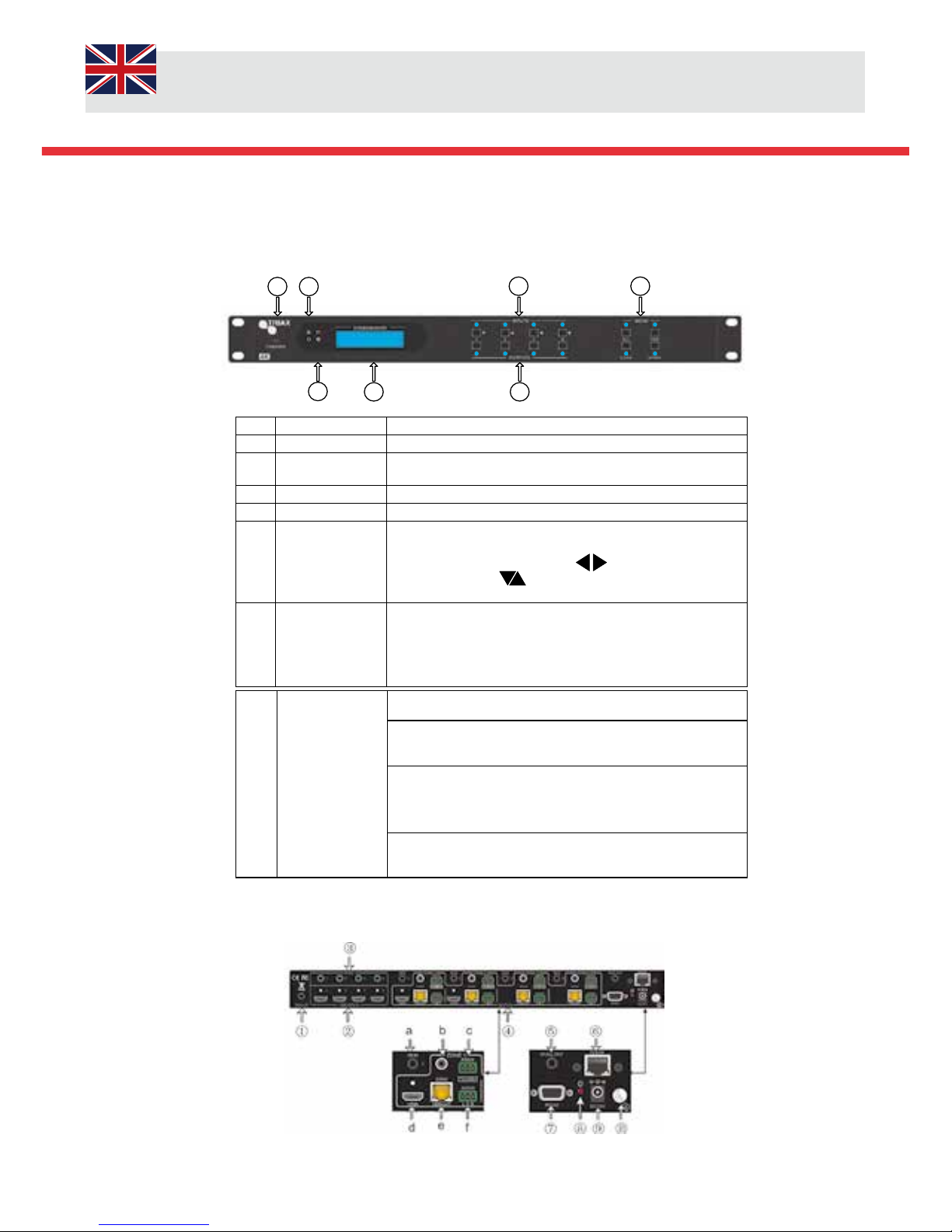
2.1.1 Front Panel
No. Name Description
①
Firmware Micro USB - firmware upgrade
②
Power
Indicator
Illuminate Green when power on, Red in Standby
③
IR In-built IR sensor, receive IR signals sent from IR remote.
④
LCD Screen Displays real-time status indication.
⑤
INPUTS/
Menu buttons
Normal mode: ranging from "1" to "4".
Enquiry mode (buttons 1~4): Press “ENTER” for >3
seconds to enter mode. Press to select
different menus, to select options, press ENTER
to confirm.
⑥
OUTPUTS buttons/ EDID
Management
buttons
Normal mode: ranging from "1" to "4". Output 1~2 support
synchronous local HDMI output.
EDID Invoking mode: press and hold EDID button for >3
seconds to enter mode, press buttons 1or
2, these switch to
the previous/next EDID data.
⑦
Function Buttons
ALL: Select all inputs / outputs
EDID management button: Enables input port to manually
capture and select the EDID data of output device.
CLEAR: Cancel an operation, like switching output
Channel or learning EDID data before it comes into effect.
The matrix will return to the previous state.
ENTER: Confirms operation. Press and hold for >3 seconds to
enter Enquiry mode.
1. Notes: Pictures shown in this manual are for reference only. Specifications are subject to change without notice.
2.1.2 Rear Panel
1 2
3
4
5
6
7
8/52
Page 9

9/52
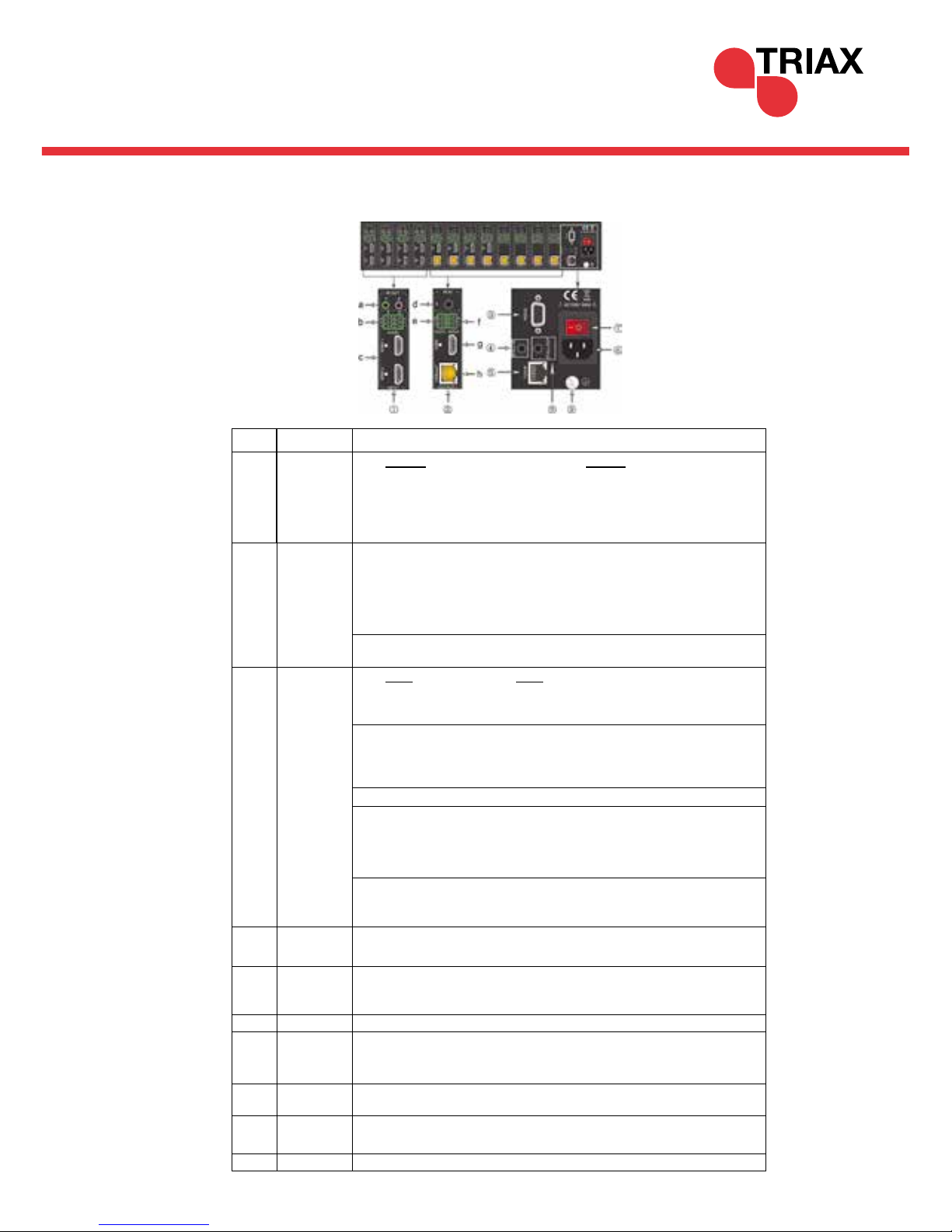
2.1.3 Rear Panel HMX 442LP4K (310037) continued
No. Name
Description
①
IR ALL IN
Pug the IR Receiver in to the 3.5mm jack socket. The allows IR signals to
pass from the Matrix to each corresponding Receiver in the zone.
②
HDMI INPUTS 4 x HDMI type A female input sockets. Plug an HDMI cable from the
Source to any of the HDMI input Sockets.
③
IR OUT
Plug an IR transmitter into the 3.5mm jack socked marked up “IR OUT” on the matrix,
ensure that the required zone is chosen, these are clearly marked up. The IR signals are sent from the receiver in the zone to the matrix, these are passed
through to enable control of the Source.
④
OUTPUTS
a. IR IN: Plug an IR receiver in to the “IR IN” 3.5mm socket on the matrix. The IR
Signals are sent from the matrix to the receiver on thought to the IR
emitter.
b. COAX: HDMI de-embedded digital audio output
c.
RS232: Serial communications between matrix and the corresponding
HDBaseT™ receiver.
d. HDMI: HDMI Type A connectors, plug an HDMI cable in to the
output socket and connect it to either a local display or AVR.
e. HDBaseT™: Uses HDBT technology to convert HDMI to
CAT5e/6. Use with HRX 1LP4K receiver
f. Audio: HDMI de-embedded stereo audio output
IR All OUT
Plug IR Twin Blaster in to the 3.5mm jack marked as “IR ALL OUT”. This func-
tion allows IR signals to be sent from the zones back through the matrix to
control 3rd party equipment such as AVR’s
⑥
TCP/IP
TCP/IP port for unit control
⑦
RS232
Serial port for unit control, 9-pin female connector, connects with control
device such as a PC.
⑧
Power Indicator Front panel Illuminate Green when powered on and RED in Standby. RED
Power on Indicator on rear panel
⑨
DC24V
DC 24V power adaptor.
⑩
Ground
Ensure that the matrix is earth bonded
⑤
Page 10
User Manual
10/52
2.2 Product Appearance of the HMX 663LP4K (310047)
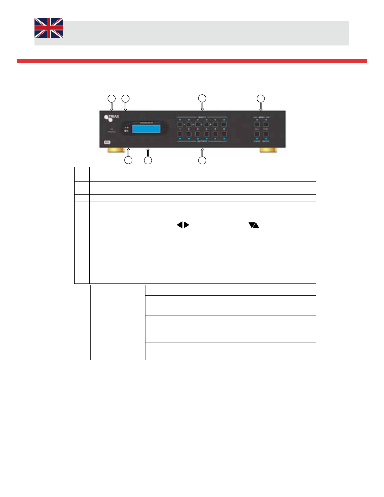
2.2.1 Front Panel
2
3
4
5
6
7
1
No. Name Description
①
Firmware Micro USB firmware update
②
Power
Indicator
Illuminate Green when power on
Illuminate Red in standby mode
③
IR In-built IR sensor, receive IR signals sent from IR remote.
④
LCD Screen Display real-time operation status.
⑤
INPUTS/ Menu
buttons
Normal mode: ranging from "1" to "6".
Enquiry mode (buttons 1~4): Press “ENTER” for >3 seconds to enter
mode. Press to select different menus, to select options. Press
ENTER to confirm.
⑥
OUTPUTS buttons/
EDID Management
buttons
Normal mode: ranging from "1" to "6". Output 1~3 support
Synchronous local HDMI output.
EDID control mode: press and hold EDID button for >3 seconds enter this
mode, buttons 1~6 correspond to the 6 embedded EDID data received
from the displays. Press any of the 6 buttons to save the embedded EDID
data.
⑦
Function Buttons
ALL: Select all inputs / outputs
EDID management button: Enables input port to manually capture and
select the EDID data of output device.
CLEAR: Cancel an operation, like switching output
Channel or learning EDID data before it comes into effect. The matrix
will return to the previous state.
ENTER: Confirms operation. Press and hold for >3 seconds to enter Enquiry
mode.
Page 11
11/52
2.2 Product Appearance of the HMX 663LP4K (310047)
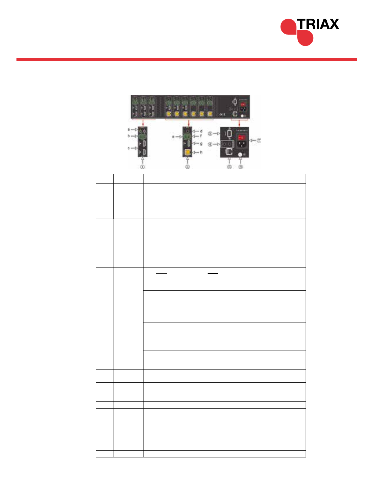
2.2.2 Rear Panel
INPUTS
b. AUDIO: Auxiliary audio input ports, 6 in total, compatible with
PCM audio sources
c. HDMI: 6 x HDMI type A female sockets. Plug an HDMI cable in to the
socket and repeat on the Source device (such as Blu-ray)
②
OUTPUTS
d. IR IN: The matrix has 6 “IR IN” 3.5mm sockets. These connect di-
rectly to the IR IN on the receivers. This forms a fixed bi-directional
transmission link.
e. RS232: The matric has six 3-pin pluggable terminal blocks, these ena-
ble fixed communication link with the RS232 port on corresponding HDBaseT™ receiver.
f. AUDIO: 6 x stereo audio outputs
g. HDMI: HDMI Type A connectors, plug an HDMI cable into
the output socket and connect it to either a local display or
AVR
.
h. HDBaseT: Uses HDBT technology to convert HDMI signals to
CAT5e/6
③
RS232
Serial port for unit control, 9-pin female connector, enables control of 3rd
party device such as a PC.
④
IR ALL IN
Plug an IR Receiver in to the “IR ALL IN” 3.5mm jack socket. Sends IR
command signals from the matrix to the receivers.
⑤
TCP/IP TCP/IP port for unit control
⑥
IR ALL OUT
Receivers IR command signals from the receivers and re-transmits
the command signals to 3rd party devices such as AVR’s.
⑦
Power
Button
Front panel Illuminate Green when powered on and RED in Standby. RED
Power on Indicator on rear panel
⑧
Power
Supply
Plug the power supply in to the Matrix, select to correct power cord for
your region.
⑨
GROUND Ensure the Matrix is earth bonded.
No. Name
Description
①
INPUTS
a. IR OUT: Plug the IR emitters in to the “IR OUT” 3.5mm jack sockets.
This allows the IR signals to be passed through the matrix to the
receiver in the select zone or to all zones. The default setting enables
all corresponding inputs to be connected to their respective outputs,
i.e. IR IN 1 to be linked to IR OUT 1.
Page 12
User Manual
12/52
2.3 Product Appearance of the HMX 884LP4K (310038)
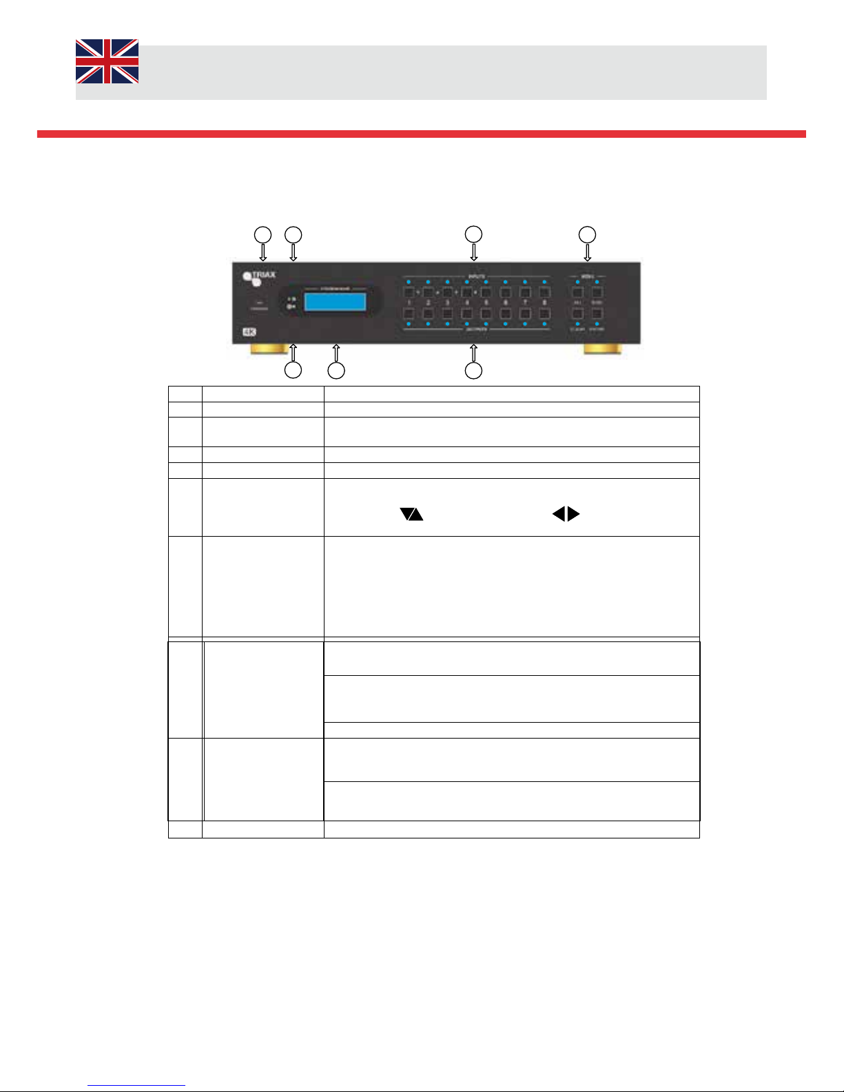
2.3.1 Front Panel
2
3
4
5
6
7
1
No. Name Description
①
Firmware Micro USB firmware update
②
Power
Indicator
Illuminate Green when power on
Illuminate Red in standby mode
③
IR In-built IR sensor, receive IR signals sent from IR remote.
④
LCD Screen Display real-time operation status.
⑤
INPUTS/ Menu
buttons
Normal mode: ranging from "1" to "8".
Enquiry mode (buttons 1~4): Press “ENTER” for >3 seconds to enter
mode. Press to select different menus, to select options. Press
ENTER to confirm.
⑥
OUTPUTS buttons/
EDID Management
buttons
Normal mode: ranging from "1" to "8". Output 1~3 support
Synchronous local HDMI output.
EDID control mode: press and hold EDID button for >3 seconds enter this
mode, buttons 1~8 correspond to the 8 embedded EDID data received
from the displays. Press any of the 8 buttons to save the embedded EDID
data.
⑦
Function Buttons
ALL: Select all inputs / outputs
EDID management button: Enables input port to manually capture and
select the EDID data of output device.
CLEAR: Cancel an operation, like switching output
Channel or learning EDID data before it comes into effect. The matrix
will return to the previous state.
ENTER: Confirms operation. Press and hold for >3 seconds to enter Enquiry
mode.
Page 13
13/52
2.3 Product Appearance of the HMX 884LP4K (310037)
2.3.2 Rear Panel
INPUTS
b. AUDIO: Auxiliary audio input ports, 8 in total, compatible with
PCM audio sources
c. HDMI: 8 x HDMI type A female sockets. Plug an HDMI cable in to the
socket and repeat on the Source device (such as Blu-ray)
②
OUTPUTS
d. IR IN: The matrix has 8 “IR IN” 3.5mm sockets. These connect
directly to the IR IN on the receivers. This forms a fixed bi-directional
transmission link.
e. RS232: The matric has 8 x 3-pin pluggable terminal blocks, these
enable fixed communication link with the RS232 port on
corresponding HDBaseT™ receiver.
f. AUDIO: 8 x stereo audio outputs
g. HDMI: HDMI Type A connectors, plug an HDMI cable into
the output socket and connect it to either a local display or
AVR
.
h. HDBaseT: Uses HDBT technology to convert HDMI signals to
CAT5e/6
③
RS232
Serial port for unit control, 9-pin female connector, enables control of 3rd
party device such as a PC.
④
IR ALL IN
Plug an IR Receiver in to the “IR ALL IN” 3.5mm jack socket. Sends IR
command signals from the matrix to the receivers.
⑤
TCP/IP TCP/IP port for unit control
⑥
IR ALL OUT
Receivers IR command signals from the receivers and re-transmits
the command signals to 3rd party devices such as AVR’s.
⑦
Power
Button
Front panel Illuminate Green when powered on and RED in Standby. RED
Power on Indicator on rear panel
⑧
Power
Supply
Plug the power supply in to the Matrix, select to correct power cord for
your region.
⑨
GROUND Ensure the Matrix is earth bonded.
No. Name
Description
①
INPUTS
a. IR OUT: Plug the IR emitters in to the “IR OUT” 3.5mm jack sockets.
This allows the IR signals to be passed through the matrix to the receiver in the select zone or to all zones. The default setting enables
all corresponding inputs to be connected to their respective outputs,
i.e. IR IN 1 to be linked to IR OUT 1.
Page 14
User Manual
14/52
3.3.2 HMX 663LP4K (310047) Connection Diagram
3. System Connection
3.1 System Applications
The Triax Matrices are ideal for Schools, Residential Pubs, Clubs and Sports Bars.
3.2 Usage Precautions
1. System should be installed in a clean environment.
2. Ensure that all of the power cords and plugs are not damaged, if there are any signs of damage DO NOT Use and send
back to the Supplier.
3. All devices should be connected before power on.
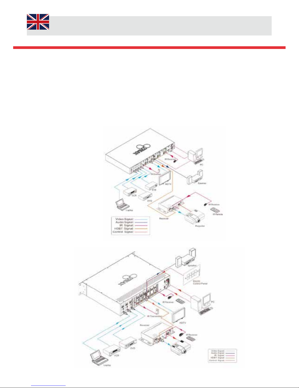
3.3 System Connection Diagrams
3.3.1 HMX 442LP4K (310037) Connection Diagram
Page 15
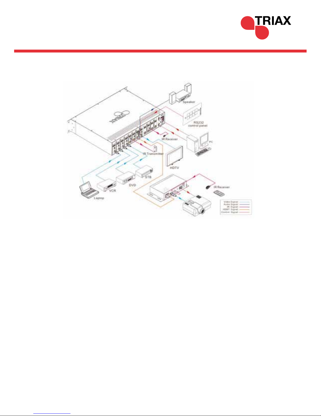
15/52
3.3.3 HMX 884LP4K (310038) Connection Diagram
3.4 Connection Procedure
1) Connect HDMI sources (e.g. DVD) to HDMI inputs of the Matrix with High Speed + Ethernet HDMI cables.
2) Connect auxiliary audio sources to the AUDIO IN ports with audio cables.
3) Connect HDBaseT receivers (e.g. HRX 1LP4K) to the HDBaseT Output ports with CAT5e or higher.
4) Connect HDMI displays (e.g. HDTV) to HDMI outputs of the Matrix or the receivers with HDMI cables
5) Connect speakers/earphones to AUDIO output ports
6) Connect the RS232 port of control device (e.g. a PC) to the RS232 port of either Matrix or far-end receivers. RS232
signal can be transmitted bi-directionally between Matrix and far-end receivers.
7) The Matrix can collect IR signal sent by the included IR remote via its built-in IR sensor or through external IR receiver
connected to the IR IN/ IR OUT ALL/ IR ALL IN port. The IR signal can be transmitted bi-directionally between Matrix and
far- end receivers.
8) Connect an AC 100V~240V power outlet and the Matrix with the AC power cord or the Transformer adaptor on the
HMX 442LP4K, Select the correct Power Plug adaptor for your region
Note:
1) Output audio is selectable via RS232 command Audio/[X]:[Y]. It’s free to select whether analogue audio or HDMI
audio to output. Default is HDMI audio. [Not applicable to HMX 442LP4K]
2) IR receivers connected to IR IN & IR ALL IN should be with
carrier. If not, send command %0900. or %0901.to activate
native carrier mode or force carrier mode in the IR matrix launched between Matrices and receivers.
Page 16

User Manual
16/52
3.5 Connection with the HRX 1LP4K (310039) HDBaseT™ Receiver
The Triax series of Matrices are PoE compatible meaning that the matrices power up the HDBaseT™ receivers such as HRX
1LP4K. Connect a CAT5e patch lead to the RJ45 output port of the matrix to the pre-installed CAT cabling, at the receiver
location there may a be RJ45 Socket or a direct cable. Plug the cable directly in to the receiver. If there is a socket insta lled
you will need to connect a patch lead between the socket and the receiver, it is very important to use a high quality cable.
Once all the connections have been made then plug in and turn on the matrix.
HMX 442LP4K
HMX 663LP4K
HMX 884LP4K
Page 17

17/52
1
2
ENTER
INPUTS OUTPUTS
4. System Operations
4.1 Front Panel Button Control
Refer to Section 2.1 Front Panel Appearance dependent on model. Basic Introduction on programming the Triax Matrices via
the front panel.
4.1.1 Switching I/O connection
To convert one input to an output: Operation “Input 1”+“Output 2”+“ENTER”
Example: Input 1 to Output 2
Note: Default setting, All IR OUT sockets correspond with the total number of HDMI INPUTS dependent on model. When you
convert an HDMI input to an output, the corresponding IR OUT will be switched synchronously.
2) To convert an input to several outputs:
Operation: “input” + “output” + “output” +… + “ENTER”
Example: Switch input 2 to output 2 and 4
2
ENTER
INPUTS
2
OUTPUTS4OUTPUTS
3) To convert an input to all outputs: Operation: “input” + “ALL” + “ENTER”
Example: Convert input 1 to all outputs
3) To convert an input to all outputs:
Operation: “Input” + “ALL” + “ENTER”
Example: Convert input 1 to all outputs
1
ALL ENTER
INPUTS OUTPUTS
LED programming sequence, The BLUE LED’s will flash 3 times when the program sequence has been saved, If there is no
BLUE LED sequence the programming has failed.
Page 18

User Manual
18/52
4.1.2 EDID Management
The Triax Series of Matrices offer EDID management as a standard feature. This allows and maintains
compatibility between devices. This procedure allows the matrix to learn the setting from a display or
TV in a particular zone.
EDID learning from output.
The matrix will learn the EDID information from the output port / zone.
Operation: Press “EDID” Press “Inputs 2” Press “Output 4” Press “Enter” in sequence and save
Example: Input 2 learns the EDID information from output 4
EDID
ENTER
INPUTS
2 4
OUTPUTS
All Input ports learn the EDID setting from one specified output sink device.
The matrix will learn the EDID information from the output port / zone 4 and be saved to ALL inputs.
Operation: Press “EDID” Press “ALL” Press “Output 4” Press “Enter” in sequence and save
Example: ALL Input learns the EDID information from output 4
EDID
ENTER
INPUTS
ALL
4
OUTPUTS
LED programming sequence, The BLUE LED’s will flash 3 times when the program sequence has been saved, If there is no
BLUE LED sequence the programming has failed.
Page 19

19/52
4.13 EDID Invoking
There are Five [HMX442LP4K] and Six types [ HMX 663LP4kK & HMX884LP4K] of embedded EDID data, The table below
illustrates the detailed information of the embedded EDID data.
HMX 663LP4K / HMX 884LP4K
Output Button EDID Data
1 1080P 3D 2CH
2 1080P 3D Multichannel
3 1080P 2D 2CH
4 1080P 2D Multichannel
5
3840x2160 2D(30Hz)
6
4096x2160 2D(30Hz)
Format: Press and hold “EDID” for 3 seconds, “INPUTS”+“OUTPUTS”+“ENTER”. Operations:
Set EDID data for one input
Operation: Press “EDID” (hold for 3 seconds to enter in EDID setting status), “INPUTS”+“OUTPUTS”+“ENTER”.
Example: Set the EDID data of INPUT 4 to the forth type of embedded EDID data:
Set EDID data for all inputs
Operation: Press “EDID” (hold for 3 seconds to enter in EDID setting status), “ALL”+“OUTPUTS”+“ENTER”.
Example: Set the EDID data of all input ports to the second type of EDID data:
EDID
ENTER
INPUTS
4 4
OUTPUTS
EDID
ENTER
INPUTS
ALL
2
OUTPUTS
To confirm that the programming has been successful the BLUE LED’s will flash 3 times at a normal speed, if unfortunately
the programming was unsuccessful the BLUE LED’s will Flash fast 3 times.
HMX 442LP4K
Output Button EDID Data
1 1080P 2D 2 CH
2 1080P 3D 2 CH
3 1080P 2D Multichannel
4 1080P 3D Multichannel
5
3840x2160 2D(30Hz)
HMX 442LP4K: Press and hold “EDID” for 3 seconds to enter EDID invoking mode, in this mode, use output buttons 1/2 to
switch among the 5 embedded EDID data. Then press “ENTER” to confirm invoking.
Format: Press and hold “EDID” for 3 seconds, “INPUTS”+“OUTPUTS 1/2”+“ENTER”.
Operations:
Invoke embedded EDID data for one input
Operation: Press “EDID” (hold for 3 seconds to enter in EDID setting status), “INPUTS”+“OUTPUTS”+“ENTER”.
Example: Set the EDID data of INPUT 2 to the forth type of embedded EDID data:
Press EDID (hold for 3 seconds) INPUT2 OUTPUT1 or OUTPUT2 to switch to the 4th EDID data ENTER.
Note: If the conversion is successful, indicators of the pressed buttons will blink green for three times at normal speed; if the
conversion failed, they will blink for three times quickly.
Page 20

User Manual
20/52
4.1.4 Enquiry
Press and Hold the “ENTER” button for 3 seconds and this will give you access to the “ENQUIRY”
Mode. Use Left and Right direction buttons to navigate the menu.
Function Items
Example Description
Check the connection
status of inputs
Y means the corresponding port is
connected with input device, N means
not.
Check the connection status of outputs
Y means the corresponding port is connected with output device, N means not.
Correspondence between
inputs and outputs
Shows the correspondence
between the 8 inputs and 8 outputs.
Check if the input is
with HDCP
Y means the input signal is with
HDCP, N means not.
Check if the output is
with HDCP
Y means the output signal is with
HDCP, N means not.
IN 1 2 3 4
Connect Y Y Y Y
OUT 1 2 3 4
Connect Y Y N N
OUT 1 2 3 4
INPUT 1 2 3 4
IN 1 2 3 4
HDCP Y Y Y N
OUT 1 2 3 4
HDCP Y Y Y N
Press and Hold the “ENTER” button for 3 seconds and this will give you access to the “ENQUIRY”
Mode. Use Left and Right direction buttons to navigate the menu.
Check Output
Resolution
Use button to check ALL output
resolutions separately.
RESOLUTION
OUT 1 1920 x 1080
To Check the Output Status
Press any output button to check its corresponding input.
Example: Check which one is the corresponding input is assigned to output 2. (Presume Output 2 corresponds to Input 1.)
Operation: Press Output 2 button, The LCD screen displays “AV: 1->2 IR: 1->2” and indicators input 1 and output
2 are corresponding the display will last for 3 seconds. Also the corresponding BLUE LED’s above the buttons will
illuminate.
4.1.5 Clear operation
When you switch output channel, learn EDID data or set EDID data, press Clear button to go “back” to the previous step
before pressing “ENTER” you confirm and access that mode or confirm changes.
4.2 IR Control
By using IR & HDBaseT transmission technology, all Matrices have the functions as follows:
1) Able to control the device or display in the Zone. From the matrices location (Local).
2) Control local input/output device remotely.
3) Control the Matrix locally/remotely.
Page 21

21/52
4.2.1 Usage of IR Remote
1. Standby Button, Press to Enter or Exit standby
mode.
2. Input Channels, range from 1~ X dependent on
model. IR commands only operate within the
actual Zone
3. Menu Button, ALL, EDID and CLEAR replicate
Front functionality
4. Navigation Buttons ENTER to
Confirm
5. Output Channels (Zone) , Range 1~8 dependent
on model.
Note: With this IR remote control unit (RCU) ALL Triax Matrices can be controlled by the built-in IR Sensor on the front of
the unit.
Page 22

User Manual
22/52
HRX 1LP4K 1 HRX 1LP4K 2 HRX 1LP4K 3 HRX 1LP4K 4 HRX 1LP4K 5 HRX 1LP4K 6 HRX 1LP4K 7 HRX 1LP4K 8
4.2.2 IR Operations
1) IR Matrix Switching
The 8 “IR OUT” ports and the 8 “IR IN” ports on the far-end Zone receivers make up an 8x8 IR matrix. Refer to schematic
below (subject to model):
4.2.3 IR Matrix Bi-directional Control
The IR Signal command is received by the HRX 1LP4K Receiver located in the zone, modulated and superimposed on to the CAT cabling
infrastructure. The IR signal is received by the matrix demodulated and returned once more to an IR signal via the IR OUT to the IR blaster which
sends the commands to the source.
Switching Operation default setting: The IR IN ports correspond to the HDMI Input sources.
Page 23

23/52
HRX 1LP4K
4.2.4 IR control setting
Control the devices located in the zones via the local IR commands at the sources location
Connect the IR emitter receiver to the IR IN port of the Triax Matrix. The users can now control the devices in the zone from the
matrix at the Source location. To enable this functionality a IR blaster needs to be plugged in to the IR Out socket on the HRX
1LP4K and has to be inline of sight of the device that you want to control.
See Schematic below (for illustration only):
To control ALL receivers in the zones a IR emitter needs to connected to the IR ALL IN port on the matrix and an IR Blaster/
transmitter connected to the IR Out socket on the HRX 1LP4K receivers. Once the commands are sent from the local source the
IR signals are modulated and passed through the CAT cable infrastructure before being demodulated at the receiver and blaster
out to the display. The Blaster must be in-line of sight of the display.
HRX 1LP4K 1
HRX 1LP4K 2
HRX 1LP4K 3 HRX 1LP4K 4 HRX 1LP4K 5 HRX 1LP4K 6
HRX 1LP4K 8
HDMI
Lead
HRX 1LP4K 7
IR Blaster
HDMI Lead
Page 24

User Manual
24/52
HD Receiver
IR Blaster
HRX 1LP4K
IR Emitter
HD Receiver RCU
Triax Matrix HMX 884LP4K
4.3 RS232 Control
4.3.1 Connection with RS232 Communication Port
The Triax Matrices and Receivers have bi-directional control which enables signal source controls such as RS 232 to be used
in either location. Both the Matrix and the receiver have RS 232 a female 9-pin D connectors / 3-pin pluggable terminal block.
The definition of its pins is listed in the table below.
4.2.5 Control local device from remote viewing area or zone
The Triax Matrices enables the end users to control the source equipment whilst in the main viewing area. This feature is
possible by installing an IR receiver connected to the IR in port on the HRX 1LP4K receiver. Using the standard remote
control for the Source device, direct the remote at the receiver which must be in-line of sight to ensure that it picks up the
IR commands.
The IR commands are modulated on to the CAT cable infrastructure and demodulated at the matrix and converted back to
IR signals IR Out port, these commands are then blaster back via the transmitter to the source device.
See schematic below:
No. Pin Function
1 N/u Unused
2 TX Transmit
3 Rx Receive
4 N/u Unused
5 Gnd Ground
6 N/u Unused
7 N/u Unused
8 N/u Unused
9 N/u Unused
Page 25

25/52
4.3.2 Installation/uninstallation of RS232 Control Software
installation Copy the control software file to the computer connected with matrix
Uninstall: Delete all the control software files in corresponding file path.
4.3.3 Basic Settings
Firstly, connect the matrix with an input source and an output sink or the network. Connect the computer which has the
installed RS232 control software. Double-click the software icon to run the software.
Here we take the software CommWatch.exe as example.
The software can be downloaded from the www.triax.com website on the support page
or directly on the product page
The interface of the control software is showed as below:
Please ensure that you have set the parameters of the COM number, baud rate, data bit, stop bit and parity bit correctly, only then
will you be able to send out commands in the command sending area.
Page 26

User Manual
26/52
Command Function
Feedback Exam-
ple
System Commands
/*Type; Inquire the models information. HMX 442LP4K
/%Lock;
Lock the front panel buttons on the
Matrix.
System Locked!
/%Unlock;
Unlock the front panel buttons on the
Matrix.
System Unlock!
/^Version; Inquire the version of firmware VX.X.X
/:Message
Off;
Turn off the feedback command from
the com port. It will only show simple
words like “SWITCH OK!”.
/:MessageOff;
/:Message
On;
Turn on the feedback command from
the com port.
/:MessageOn;
Demo.
Switch to the “demo” mode, convert
input and output in turn like1B1, 1B2,
…4B3, 4B4, 1B1… and so on .The
switching interval is 2 seconds.
Demo Mode
AV: 01-> 01
AV: 01-> 02
AV: 01-> 03
AV: 01-> 04
AV: 02-> 01
…
Undo. To cancel the previous operation.
Undo Ok!
Out 01 02 03 04
In 01 01 01 01
Operation Commands
[x]All.
Transfer signals from the input channel [x] to all output channels
X To All.
(X=01~04)
All#.
Transfer all input signals to the corresponding output channels respectively like 1->1, 2->2…
All Through.
All$. Switch off all the output channels. All Closed.
[x]#.
Transfer signals from the input channel [x] to the output channel [x].
X Through.
(X=01~04)
[x]$. Switch off the output channel [x].
X Closed.
(X=01~04)
[x]@. Switch on the output channel [x]. X Open. (X=01~04)
All@. Switch on all output channels.
All Open.
4.3.4 RS232 Communication Commands (HMX 442LP4K)
Baud rate: 9600 Data bit: 8 Stop bit: 1 Parity bit: none
Page 27

27/52
Command Function Feedback Example
[x1]V[x2].
Transfer the AV signal from the input
channel [x1] to one or several output
channels ([x2], separate output channels
with comma).
AV: X1-> X2
(X1/X2=01~04)
[x1]B[x2].
Transfer the AV and IR signal from input
channel [x1] to one or several output
channels ([x2], separate output channels
with comma).
AV: X1-> X2
(X1/X2=01~04)
[x1] R[x2].
Transfer the IR signal from output [x1] to
input [x2].
IR: X1-> X2(X1、
X2=01~04)
Status[x].
Check the I/O connection status of output
[x]
AV: Y-> X
(X=01~04, Y=01~04)
Status.
Inquire the input channel to the output
channels one by one.
AV: 01-> 01
AV: 02-> 02
AV: 03-> 03
AV: 04-> 04
Save[Y].
Save the present operation to the preset
command [Y], ranges from 0 to 9.
Save To FY (Y=0-
9)
Recall[Y]. Recall the preset command [Y].
Recall From FY (Y=0
-9)
Clear[Y]. Clear the preset command [Y]. Clear FY (Y=0-9)
PWON. Work in normal mode. PWON
PWOFF.
Enter into standby mode and cut off the
power supply to HDBaseT receivers.
PWOFF
STANDBY.
Enter into standby mode. (Do not cut off
the power supply to HDBaseT receivers,
press other buttons or send other commands to start.)
STANDBY
/%[Y]/[X]:[Z].
HDCP management command.
[Y] is for input (value: I) or output (value:
O); [X] is the number of the port, if the
value of X is ALL, it means all ports; [Z] is
for HDCP compliant status, the value
may be 1 (HDCP compliant) or 0 (not
HDCP compliant).
/%[Y]/[X]:[Z].
DigitAudioON
[x].
Enable HDMI audio output of port x.
X=1, 2, 3, 4, enable this port.
X=5, enable all the 4 ports.
DigitAudio ON with
[x]
Page 28

User Manual
28/52
Command Function Feedback Example
DigitAudio
OFF[x].
Disable HDMI audio output of port x.
X=1, 2, 3, 4, disable this port.
X=5, disable all the 4 ports.
DigitAudio OFF with
[x]
/+[Y]/
[X]:******.
Set communication between PC and
HDBaseT receiver.
Y is for RS232 port (connect with RS232
port of HDBaseT receiver)
Y= 1~5 or A~H, The value of Y is
defined into the following meanings
(in a given baud rate depended by
the value of X):
Y = 1~4, send this command to the cor-
responding HDBaseT receiver to
control far-end device.
Y = 5, send this command to all
HDBaseT receivers to control all farend devices.
Y = A, B, C, or D
Y = E, F, G, or H
For items c or d, send this command,
it will be saved to the matrix switcher
but taken without action to corresponding HDBaseT receiver. And its
command function will be effective
almost at the same time when you
send the command PWON (for item
c) or PWOFF (for item d).
Note:
A & E are for port 1. B & F are for
port 2.
C & G are for port 3. D & H are for
port 4.
X is for bound rate, its value ranges from
1 to 7 (1--2400, 2--4800, 3--9600, 4-19200, 5--38400, 6—57600, 7--
115200)
***** is for data (max 48 Byte)
******
Page 29

29/52
Command Function Feedback Example
EDIDH[x]B[y].
Input port [y] learns the EDID from out-
put port [x].
If the EDID data is available and the au-
dio part supports not only PCM mode,
then force-set it to support PCM mode
only. If the EDID data is not available,
then set it as inialized EDID data.
EDIDH[x]B[y]
EDIDPCM[x].
Set the audio part of input port [x] to
PCM format in EDID database.
EDIDPCM[x]
EDIDG[x].
Get EDID data from output [x] and dis-
play the output port number.
Hexadecimal EDID
data and carriage
return character
EDIDMInit.
Restore the factory default EDID data of
every input.
EDIDMInit.
EDIDM[X]B[Y].
Manually EDID switching. Enable input
[Y] to learn the EDID data of output[X].
If the EDID data is not available, then set
it as inialized EDID data.
EDIDM[X]B[Y]
EDIDUpgrade
[x].
Upgrade EDID data via the RS232 port.
[x] is the input port, when the value of X
is 9, it means to upgrade all input ports.
When the switcher receives the com-
mand, it will show a message to prompt
you to send EDID le (.bin le). Opera-
ons will be canceled aer 10 seconds.
Please cut o all connecons of
HDBaseT ports.
Please send the
EDID le
EDID/[x]/[y].
Set the EDID data of input port [x] to
built-in EDID No.[y].
[y]=1~5, correspond to the 5 embedded
EDID data separately
EDID/[x]/[y]
Page 30

User Manual
30/52
Command Function Feedback Example
UpgradeIntEDID[x].
Upgrade one of the 5 embedded EDID data, x is
the serial number for EDID data:
1. 1080P 2D 2CH
2. 1080P 3D 2CH
3. 1080P 2D Mulchannel
4. 1080P 3D Mulchannel
5. 3840x2160 2D (30Hz)
When the switcher gets the command, it will
show a message to send EDID le (.bin le). Oper-
aons will be invalid aer 10 seconds.
Please send the EDID le
GetIntEDID[x]. Return the embedded EDID data ranked x, [x]=1~5
GetInPortEDID[X]. Return the EDID data of input [x], [x]=1~4
%0801.
Auto HDCP management, acvate carrier nave
mode
%0801
%0900. Switch to carrier nave mode. Carrier nave
%0901. Switch to force carrier mode. Force carrier
%0911. Reset to factory default. Factory Default
%9951. Check the command sent by port 1 when PWON. Port 1:data when PWON
%9952. Check the command sent by port 2 when PWON. Port 2:data when PWON
%9953. Check the command sent by port 3 when PWON. Port 3:data when PWON
%9954. Check the command sent by port 4 when PWON. Port 4:data when PWON
%9955. Check the command sent by port 1 when PWOFF. Port 1:data when PWOFF
%9956. Check the command sent by port 2 when PWOFF. Port 2:data when PWOFF
%9957. Check the command sent by port 3 when PWOFF. Port 3:data when PWOFF
%9958. Check the command sent by port 4 when PWOFF. Port 4:data when PWOFF
Page 31

31/52
Command Function Feedback Example
Clear[Y].
Clear the preset command [Y].
Clear FY (Y=0-9)
PWON. Work in normal mode. PWON
PWOFF.
Enter into standby mode and cut off the
power supply to HDBaseT receivers.
PWOFF
STANDBY.
Enter into standby mode. (Do not cut off
the power supply to HDBaseT receivers,
press other buttons or send other
commands to start.)
STANDBY
Audio/[X]:[Y].
Select HDMI audio or analogue audio
as audio source for output 1~8.
Audio/[X]:[Y]. X=1~8,
Y=0 (HDMI audio) or 1
(Analogue audio).
/%[Y]/[X]:[Z].
HDCP management command.
[Y] is for input (value: I) or output (value:
O); [X] is the number of the port, if the
value of X is ALL, it means all ports; [Z] is
for working status (value: 1 or 0).
/%[Y]/[X]:[Z]. Y=I/
O;
X=1~8 or ALL; Z=1/0
[x1]R[x2].
Transfer the IR signal from input channel
[x1] to output channel [x2].
IR: X1-> X2 (X1/
X2=1~8)
DigitAudioON[
x].
Enable HDMI audio output of port x.
X=1, 2, 3, 4, 5, 6, 7, 8, enable this
port.
X=9, enable all the 8 ports.
DigitAudio ON with [x]
x=1~8 or ALL
DigitAudioOF
F[x].
Disable HDMI audio output of port x.
X=1, 2, 3, 4, 5, 6, 7, 8, disable this
port.
X=9, disable all the 8 ports.
DigitAudio OFF with
[x]
x=1~8 or ALL
*Note: outputs depends on matrix model
Page 32

User Manual
32/52
Command Function Feedback Example
System Commands
/*Type; Enquires models information. “Triax Model”
/%Lock; Locks the front panel buttons on the Matrix. System Locked!
/%Unlock;
Unlocks the front panel buttons on the
Matrix.
System Unlock!
/^Version; Displays Firmware version VX.X.X
/:Message Off;
Turn off the feedback command from the
com port. It will only show simple words
like “SWITCH OK!”.
/:Message Off;
4.3.4 RS232 Communication Commands (HMX 663LP4K & HMX 884LP4K)
Baud rate: 9600 Data bit: 8 Stop bit: 1 Parity bit: none
Command
Function Feedback Example
/:MessageOn;
Turn on the feedback command from the
com port.
/:MessageOn;
Demo.
Switch to the “demo” mode, convert input
and output in turn like1B1, 1B2, …8B7,
8B8, 1B1… and so on .The switching
interval is 2 seconds.
Demo Mode
Undo. To cancel the previous operation. Undo Ok!
Operation Commands
[x]All.
Transfer signals from the input channel [x]
to all output channels
X To All. (X=1~8)
All#.
Transfer all input signals to the
corresponding output channels
respectively like 1->1, 2->2…
All Through.
All$. Switch off all the output channels. All Closed.
[x]#.
Transfer signals from the input channel [x]
to the output channel [x].
X Through. (X=1~8)
[x]$. Switch “OFF” the output channel [x]. X Closed. (X=1~8)
[x]@. Switch “ON” the output channel [x]. X Open. (X=1~8)
All@. Switch “ON” all output channels. All Open.
[x1]V[x2].
Transfer the AV signal from the input
channel [x1] to the
output channel [x2].
AV: X1-> X2 (X1/
X2=1~8)
[x1]B[x2].
Transfer the AV and IR signal from the
input channel [x1] to the output channel
[x2].
AV: X1-> X2 (X1/
X2=1~8)
Status[x].
Check the I/O connection status of output
[x]
AV: Y-> X (X=1~8,
Y=1~8)
Status.
Enquire the input channel to the output channels one by one. This example
shows the 8x8.
AV: 1-> X1
AV: 2-> X2
AV: 3-> X3
AV: 4-> X4
AV: 5-> X5
AV: 6-> X6
AV: 7-> X7
AV: 8-> X8
Save[Y].
Save the present operation to the preset
command [Y], ranges
from 0 to 9.
Save To FY (Y=0
-9)
Recall[Y].
Recall the preset command [Y].
Recall From FY
(Y=0-9)
Page 33

33/52
Command Function Feedback Example
Clear[Y].
Clear the preset command [Y].
Clear FY (Y=0-9)
PWON. Work in normal mode. PWON
PWOFF.
Enter into standby mode and cut off the
power supply to HDBaseT receivers.
PWOFF
STANDBY.
Enter into standby mode. (Do not cut off
the power supply to HDBaseT receivers,
press other buttons or send other
commands to start.)
STANDBY
Audio/[X]:[Y].
Select HDMI audio or analogue audio
as audio source for output 1~8.
Audio/[X]:[Y]. X=1~8,
Y=0 (HDMI audio) or 1
(Analogue audio).
/%[Y]/[X]:[Z].
HDCP management command.
[Y] is for input (value: I) or output (value:
O); [X] is the number of the port, if the
value of X is ALL, it means all ports; [Z] is
for working status (value: 1 or 0).
/%[Y]/[X]:[Z]. Y=I/
O;
X=1~8 or ALL; Z=1/0
[x1]R[x2].
Transfer the IR signal from input channel
[x1] to output channel [x2].
IR: X1-> X2 (X1/
X2=1~8)
DigitAudioON[
x].
Enable HDMI audio output of port x.
X=1, 2, 3, 4, 5, 6, 7, 8, enable this
port.
X=9, enable all the 8 ports.
DigitAudio ON with [x]
x=1~8 or ALL
DigitAudioOF
F[x].
Disable HDMI audio output of port x.
X=1, 2, 3, 4, 5, 6, 7, 8, disable this
port.
X=9, disable all the 8 ports.
DigitAudio OFF with
[x]
x=1~8 or ALL
*Note: outputs depends on matrix model
Page 34

User Manual
34/52
Command Function Feedback Example
/+[Y]/[X]:******.
Set communication between PC and
HDBaseT receiver.
① Y is for RS232 port (connect with
RS232 port of HDBaseT receiver)
Y= 1~9 or A~P, The value of Y is
defined into the following meanings
(in a given baud rate depended by the
value of X):
a. Y = 1~8, send this command to the
corresponding HDBaseT receiver to
control far-end device.
b. Y = 9, send this command to all
HDBaseT receivers to control all
far-end devic
es.
c. Y = A, B, C, D, E, F, G or H
d. Y = I, J, K, L, M, N, O or P
For items c or d, send this command,
it will be saved to the matrix switcher
but taken without action to
corresponding HDBaseT receiver.
And its command function will be
effective almost at the same time
when you send the command PWON
(for item c) or PWOFF (for item d).
Note:
A & I are for port 1. B & J are for port
2.
C & K are for port 3. D & L are for
port 4.
E & L are for port 5. F & N are for
port 6.
G & O are for port 7. H & P are for
port 8.
② X is for bound rate, its value ranges
from 1 to 7 (1--2400, 2--4800,
3--9600, 4--19200, 5--38400,
6—57600, 7--115200)
③ ***** is for data (max 48 Byte)
/+[Y]/[X]:******.
Page 35

35/52
Command Function Feedback Example
EDIDH[x]B[y].
Input port [y] learns the EDID from output
port [x].
If the EDID data is available and the audio
part supports not only PCM mode, then
force-set it to support PCM mode only. If
the EDID data is not available, then set it
as initialized EDID data.
EDIDH[x]B[y].
EDIDPCM[x].
Set the audio part of input port [x] to PCM
format in EDID database.
EDIDPCM[x].
EDIDG[x].
Get EDID data from output [x] and display
the output port number.
Hexadecimal EDID data and carriage return character
EDIDMInit.
Restore the factory default EDID data of
every input.
EDIDMInit.
EDIDM[X]B[Y].
Manually EDID switching. Enable input[Y]
to learn the EDID data of output[X]. If the
EDID data is not available, then set it as
initialized EDID data.
EDIDM[X]B[Y].
EDIDUpgrade
[x].
Upgrade EDID data via the RS232 port.
[x] is the input port, when the value of X is
9, it means to upgrade all input ports.
When the switcher receives the
command, it will show a message to
prompt you to send EDID file (.bin file).
Operations will be cancelled after 10
seconds. P
lease cut off all connections of
HDBaseT ports.
Please send the
EDID file
EDID/[x]/[y].
Set the EDID data of input port [x] to
built-in EDID No.[y].
[y]=1~4, correspond to the 4 embedded
EDID data
EDID/[x]/[y].
Page 36

User Manual
36/52
Command Function Feedback Example
UpgradeIntED ID
[x].
Upgrade one of the 6 embedded EDID
data, x is the serial number for EDID data
1. 1080P 3D 2CH
2. 1080P 3D Multichannel
3. 1080P 2D 2CH
4. 1080P 2D Multichannel
5. 3840x2160 2D (30Hz)
6. 4096x2160 2D (30Hz)
When the switcher gets the command, it will
show a message to send EDID file (.bin
file). Operations will be invalid after
10 seconds.
Please send the
EDID file
GetIntEDID[x].
Return the embedded EDID data ranked x,
[x]=1~6
GetInPortEDI D
[X].
Return the EDID data of input [x], [x]=1~8
%0801.
Auto HDCP management, activate carrier
native mode
%0801.
%0900. Switch to carrier native mode.
Carrier native
%0901. Switch to force carrier mode.
Force carrier
%0911. Reset to factory default. Factory Default
%9951.
Check the command sent by port 1 when
PWON.
Port 1:data when
PWON
%9952.
Check the command sent by port 2 when
PWON.
Port 2:data when
PWON
%9953.
Check the command sent by port 3 when
PWON.
Port 3:data when
PWON
%9954.
Check the command sent by port 4 when
PWON.
Port 4:data when
PWON
%9955.
Check the command sent by port 5 when
PWON.
Port 5:data when
PWON
%9956.
Check the command sent by port 6 when
PWON.
Port 6:data when
PWON
%9957.
Check the command sent by port 7 when
PWON.
Port 7:data when
PWON
Page 37

37/52
Command Function Feedback Example
%9958.
Check the command sent by port 8 when
PWON.
Port 8:data when
PWON
%9941.
Check the command sent by port 1 when
PWOFF.
Port 1:data when
PWOFF
%9942.
Check the command sent by port 2 when
PWOFF.
Port 2:data when
PWOFF
%9943.
Check the command sent by port 3 when
PWOFF.
Port 3:data when
PWOFF
%9944.
Check the command sent by port 4 when
PWOFF.
Port 4:data when
PWOFF
%9945.
Check the command sent by port 5 when
PWOFF.
Port 5:data when
PWOFF
%9946.
Check the command sent by port 6 when
PWOFF.
Port 6:data when
PWOFF
%9947.
Check the command sent by port 7 when
PWOFF.
Port 7:data when
PWOFF
%9948.
Check the command sent by port 8 when
PWOFF.
Port 8:data when
PWOFF
%9961.
Check the system locking status.
System Locked/ Unlock!
%9962.
Check the status while in standby mode.
STANDBY/PWON/ PWOFF
%9963.
Check the working mode of infrared
carrier.
Carrier native/ Force carrier
%9964.
Check the IP address.
IP:192.168.0.178 (default)
Page 38

User Manual
38/52
Command Function Feedback Example
%9966.
Check the audio sources of all outputs
Channel 1 is HDMI Audio
Channel 2 is HDMI Audio
Channel 3 is HDMI Audio
Channel 4 is HDMI Audio
Channel 5 is HDMI Audio
Channel 6 is HDMI Audio
Channel 7 is Analog
Audio
Channel 8 is HDMI Audio
%9971.
Check the connection status of the inputs.
In 1 2 3 4
Connect N Y Y Y In 5 6
7 8
Connect N Y Y Y
%9972.
Check the connection status of the
outputs.
Out 1 2 3 4
Connect N Y Y Y Out 5 6
7 8
Connect N Y Y Y
%9973.
Check the HDCP status of the inputs.
In 1 2 3 4
HDCP N N Y Y In 5 6
7 8
HDCP N N Y Y
%9974.
Check the HDCP status of the outputs.
Out 1 2 3 4
HDCP N N Y Y Out 5 6
7 8
HDCP N N Y Y
%9975.
Check the I/O connection status.
Out 1 2 3 4
In 1 2 3 4
Out 5 6 7 8
In 5 6 7 8
Page 39

39/52
Command Function Feedback Example
%9976.
Check the output resolution.
Resolution
Out 1 0000x0000
Out 2 1920x1080
Out 3 1920x1080
Out 4 1920x1080
Out 5 0000x0000
Out 6 1920x1080
Out 7 1920x1080
Out 8 1920x1080
%9977.
Check the status of digital audio of output
channels.
Out 1 2 3 4
Audio Y Y Y Y Out
5 6 7 8
Audio Y Y Y Y
%9978.
Check the HDCP compliant status of the
inputs.
In 1 2 3 4
HDCPEN Y Y Y Y In
5 6 7 8
HDCPEN Y Y Y Y
Note:
1) Please disconnect all the twisted pairs before sending command EDIDUpgrade[X].
2) In above commands, “[”and “]” are symbols for easy reading and do not need to be typed in actual operation.
3) Please remember to end the commands with the ending symbols “.” and “;”.
4) Type the command carefully, it is case-sensitive.
4.4 RS232 Control Modes
To control the Triax Matrices, you need to connect its 9 pin female RS232 port to a PC’s RS232 port, or you can just connect
any one of the HDBaseT receiver’s RS232 port with PC (RS232 command can be transmitted to the matrices via the twisted
pair). By using RS232 control software and with right specification settings, you are able to control the matrices.
Page 40

User Manual
40/52
HRX 1LP4K
4.4.1 Control Triax Matrix locally
4.4.2 Control Triax Matrix from the Zones
4.4.3 Control 3rd-Party Device Locally
Connect the 9 pin female RS232 port of the Matrix to the PC, by using the RS232 command “/+[Y]/[X]:******.”, you are able
to control the 3rd-party device connected with the HDBaseT receiver.
Please refer to the detailed command description in 4.3.4 RS232 Commands.
HRX 1LP4K
Page 41

41/52
4.4.4 Bi-directional RS232 Control
By connecting one RS232 port to a PC (or controlled device), and connecting the RS232 port of corresponding HDBaseT
receiver with controlled device (or PC), the RS232 signal is able to be transmitted bi-directionally.
Control far-end device locally from matrix
Connect the RS232 (3-pin pluggable terminal block) port in any zone to PC, and connect the controlled RS232 device (3rd
party device) to the corresponding (same zone as PC) receiver, see below:
HRX 1LP4K
Control the Matrix and 3rd Party control from a remote zone
Connect the RS 232 (3-pin pluggable terminal block) in to the marked port on the matrix where the 3rd
party device is locally situated. Connect the PC to the RS 232 port on the receiver as shown below.
HRX 1LP4K
Page 42

User Manual
42/52
4.5 TCP/IP Control
4.5.1 Control Modes
Control of the Triax Matrix via TCP/IP from remote zones
TCP/IP default settings: IP is 192.168.0.178, Gateway is 192.168.0.1, and Serial Port is 8080. IP & Gateway can be changed as
you need, Serial Port cannot be changed.
Control the matrix from a single PC
Connect the PC to the RJ 45 HDBaseT port on the matrix, set the IP address and gateway to the same IP and gateway
as the matrix (Default:192.168.0.178)
Control the Matrix by PC (s) on a Network (LAN)
Connect the Matrix and the PC to the router via a direct network connection as shown in the example
below. Set the IP and Default gateway of the matrix to the same as the router’s. If the settings are correct
the Matrix and the PC are on the same network they will be able to communicate with each other.
Page 43

43/52
Follow the steps below:
1. Connect the PC’s Ethernet port to the TCP/IP port on the Matrix using a RJ45 standard patch lead
2. Make note of your PC’s IP address and default gateway settings
3. Set the PC’s IP settings and Default gateway to be in the same range as the matrix
4. Change the IP address and the default gateway setting of the matrix (which is on the label stuck to the unit) to an address
within the same range as the router
5. Port 4001
4.5.2 GUI for TCP/IP control
The Triax series of Matrices come with an on-board GUI for convenient TCP/IP control. The GUI allows
the user to interact with the matrix through graphical icons and visual indicators. To access the web
browser type in the following IP address 192.168.0.178. The screen below will be shown.
There are two logins for each matrix one for the Administrator and the other for User.
Default Username: admin and the password is: admin
Default Username: user and the password is: user
The administrator has more rights and can access and configure settings whilst the User can only view with minimal access to
settings.
Page 44

User Manual
44/52
Main interface: The screen shot below shows after logging in the Inputs and Output configuration I/O. The button matrix displays
every possible connection between every input and output, Administrators can carry on the connection by clicking on the
corresponding button.
Users display is locked to give minimal access. If any changes are made press “Save” and Cancel to “Exit” without making
changes.
Interface: Set Title Bar Label, LCD Readout and button labels, press “Save” to save all changes.
Page 45

45/52
Configuration: Set HDCP compliance status for every input and manage EDID.
See Screen shot below.
Network: Enquire and configure network settings including MAC address, IP address, subnet mask and default gateway.
Note: Log in as User access to main interface only.
4.5.3 GUI Updates
All Triax GUI support online updates, visit http://192.168.0.178:100. Type in the Username and password to log in to the
configuration interface. Click Administration at the source menu to get Upload Program as shown below.
Select the desired update file and press Appl y to start the upgrade.
Page 46

User Manual
46/52
4.5.5 Firmware Update via USB
The Triax Series of Matrices can have their firmware updated via USB. For assistance please contact technicalsupport@triax.co.uk
Download the latest upgrade file, copy the exe.file to the PC and double click on the file to start the process.
When the program is running it will display the update dialogue box shown below, Press the Button and choose the
upgrade file to be downloaded and press the button.
Once this update has finished and is accepted a new window will appear showing the message Update Success
Note: The COM number connected to the PC is only available when it is in the range of 1~9.
Page 47

47/52
5. Specifications, For All Triax Matrices, HMX 442LP4K , HMX 663LP4K and HMX 884LP4K
Video Input Video Output
Input
4, 6 or 8, HDMI
Output
2, 3, or 4 HDMI
4, 6, or 8 HDBaseT
Input
Connector
Female HDMI
Output Connector
Female HDMI
Female RJ45 (with LED indicators)
Input Level T.M.D.S. 2.9V~3.3V Output Level T.M.D.S. 2.9V~3.3V
Input
Impedance
100Ω (Differential)
Output
Impedance
100Ω (Differential)
HDBaseT Outputs
Up to 70m1080P@60Hz/
40m4Kx2K@30Hz
Video General
Gain 0 dB Bandwidth 10.2 Gbit/s
Video Signal
HDMI (or DVI-D)
Maximum Pixel Clock
225MHz
Resolution
Range
Up to 4Kx2K, 1080P 3D
Switching Speed
200ns (Max.)
Max Pixel
Clock
225MHz
EDID Management
In-built EDID data and
manual EDID
management
HDCP
Supports HDCP 1.4, auto detecting for HDCP status& selectable HDCP status
Audio General
Output Signal
Analogue audio
Output
Connector
3-pin pluggable
terminal block
PCM Format
Distortion:
0.1% 32Ω/70mW@1KHz,
0.1%16Ω/105mW @1KHz
Frequency
Response
20Hz~20KHz
CMRR
>90dB @20Hz ~ 20KHz
Control Parts
Control Ports dependant on
model
4, 6, 8 IR OUT (green
and red)
4, 6, 8 IR IN (black)
1 IR ALL OUT (black)
1 IR ALL IN (black)
1 TCP/IP (female RJ45)
1 RS232 (9 pin female)
Panel Control
Front panel buttons
4, 6, 8 RS232s (3-pin
pluggable terminal blocks)
IR Control
In-built IR sensor, Ex-
tended IR receiver
RS232
Control
9 pin female
TCP/IP Control
Works with In-built web GUI
General
Power Supply
DC 24V 2.5A
100V~240V AC
Power
Consumption
48W HMX 442LP4K,
80W HMX 663LP4K,
103W HMX 884LP4K (full
load)
Temperature
-10 ~ +40℃
Reference
Humidity
10% ~ 90%
Dimension (W*H*D)
HMX 442LP4K
HMX 66sLP4K
HMX 884LP4K
437 x 44 x 235 mm
437 x 87.8 x 380 mm
437 x 87.8 x 380 mm
Weight
2.0kg
5.3kg
5.4kg
Page 48

User Manual
48/52
Problems Causes Solutions
Colour lose or no video
signal output
The connecting cables may
not be connected correctly
or it may be broken.
Check whether the cables are connected correctly
and in good condition.
Fail or loose connection
Make sure there is good connection
No output i mage when
switching
No signal at the input /
output end
Check with oscilloscope or multi-meter if there is any signal at
the input/ output end.
Fail or loose connection
Make sure the connection is good
Input source is with HDCP
while the HDCP
compliance is switched
off.
Send command
/%[Y]/[X]:1. or change HDCP compliance status in GUI.
The display doesn’t support the input resolution.
Switch for another input source or enable the display to
learn the EDID data of the input.
Cannot control the
device via front panel
buttons
Front panel buttons are
locked.
Send command /%Unlock; or select unlock in GUI interface to
unlock
Cannot control the
device via IR remote
The battery “DEAD” Change for new battery.
The IR remote is broken.
Send it to authorized dealer for repairing or replace
Beyond the effective range
of the
IR signal or not
pointing at the IR receiver
Adjust the distance and angle and point right at the IR
receiver.
The IR receiver connected
to IR IN/ IR ALL IN port is
not with carrier
Replace IR receiver
Power Indicator remains
off when powered on
Fail or loose power
connection
Check whether the cables are connected correctly
6. Troubleshooting and Maintenance
Page 49

49/52
EDID management does
not work normally
The HDMI cable is broken
at the output end.
Change for another HDMI cable which is in good
working condition.
There is a blank screen on
the display when switching
The display does not support the resolution of the
video source.
Switch again.
Manage the EDID data manually to make the resolution of the video source automatically compliant with
the output resolution.
Cannot control the device
by control device (e.g. a
PC) through RS232 port
Wrong connection
Check to ensure the connection between
the control device and the unit
Wrong RS232
communication parameters
Type in correct RS232 communication parameters:
Baud rate:600;
Data bit: 8;
Stop bit: 1;
Parity bit: none
Broken RS232 port
Send it to authorized dealer for checking.
Static becomes stronger
when connecting the video
connectors
Bad grounding
Check the grounding and make sure it is
connected well.
Cannot control the device
by RS232 / IR remote /
front panel buttons
The device has already
been broken.
Send it to authorized dealer for repairing.
If the problem persists after following the above troubleshooting steps, seek further assistance from authorised distributors or
contact Triax sales and support at:
International support@triax.dk
UK support@triax.co.uk.
7. After-sales Service
In the unlikely event of an issue occurring with this product, please contact your point of sale. Proof of purchase will be need to
be supplied.
The product must be correctly installed and operated in accordance with the instructions contained in this operating manual.
For technical support, please contact your installer.
Please state potential issue and what test procedures have been carried out.
Page 50

User Manual
50/52
Notes - for your personal use
Page 51

Notes - for your personal use
51/52
Page 52

triax.com
Contact
triax.com/contact
08-2015A
SUPPORT
Power over Ethernet
READY
by-pass
RJ45
RS232
4x
 Loading...