

Page 1
AssemblyInstruction
CGS470
Model Itemno.
CGS 470 325010
Version 18 Date 01/2017 EN
Page 2

Contents
1 Safety regulations ..............................................................................................3
2 General information ..........................................................................................3
2.1 Scope of delivery ............................................................................... 3
2.2 Meaning of the symbols used ............................................................... 4
2.3 Technical data.................................................................................... 4
2.4 Description ........................................................................................ 5
3 Installation ........................................................................................................7
3.1 Retrofitting a CA module ..................................................................... 7
3.2 Setting the operating voltage of the CA module ..................................... 8
3.3 Installing the digital module ................................................................. 9
3.4 Connecting the digital module ........................................................... 10
4 The control panel at a glance ...........................................................................11
4.1 Menu items ...................................................................................... 11
4.2 Functions of the control panel buttons .................................................. 11
5 Programming ..................................................................................................12
5.1 Preparation...................................................................................... 12
5.2 Programming procedure .................................................................... 13
5.3 Programming the digital module ......................................................... 15
Selecting the module / channel strip ................................................... 16
Tuner .............................................................................................. 16
LNB oscillator frequency .................................................................... 17
CA module, Card information ............................................................ 18
Input symbol rate .............................................................................. 18
Input frequency ................................................................................ 19
Station filter ..................................................................................... 20
Audio stream for a TV channel ........................................................... 21
Volume level .................................................................................. 21
Identification of the stereo / dual tone ................................................. 22
Selecting the picture format ............................................................... 22
Picture format signal, Teletext mode .................................................... 23
Activating test lines ........................................................................... 23
Teletext subtitle pages and Standard ................................................... 24
Activating teletext subtitle pages and setting the standard ................ 24
Activating DVB subtitle pages ....................................................... 25
Black bar ................................................................................... 25
Storing data .................................................................................... 26
6 Final procedures .............................................................................................. 27
- 2 - CGS 470
Page 3
1 safety regulations
• The standards IEC/EN/DIN EN 50083 resp. IEC/EN/DIN EN 60728 must
be observed.
• Do not perform installation and service work during thunderstorms.
• Assembly, installation and servicing should be carried out by authorised
electricians.
• Switch off the operating voltage of the system before beginning with assembly or service work.
• Avoid short circuits!
• Observe the relevant standards, regulations and guidelines on the installation and operation of antenna systems.
• To ensure electromagnetic compatibility, make sure all connections are tight
and the covers are screwed on securely.
• No liability is accepted for damage caused by faulty connections or inappropriate handling of the device.
Check the head-end station CSE 2800 according to the safety instructions
listed in their assembly instruction.
Take precautions to prevent static discharge when working on the device!
Electronic devices should never be disposed of in the household rubbish. In
accordance with directive 2002/96/EC of the European Parliament and the
European Council from January 27, 2003 which addresses old electronic and
electrical devices, such devices must be disposed of at a designated collection
facility. At the end of its service life, please take your device to one of these
public collection facilities for proper disposal.
2 general information
2.1 sCo pe of d e livery
1 CGS 470 module
1 AV cable
1 CD (assembly instructions)
1 Brief Assembly Instructions
- 3 - CGS 470
Page 4
2.2 mea ning of t he sy mbols u s ed
Important note
—> General note
–
–
/
/
Optional use of the buttons
• Performing works
2.3 teChniC al data
The requirements of the following are met:
2011/65/EU, 2014/30/EU, 2014/35/EU
The product fulfils the guidelines and standards for CE labelling.
Unless otherwise noted all values are specified as "typical".
RF input:
Frequency range: ....................................................... 950 … 2150 MHz
Level: ..................................................................... 60 dBμV … 80 dBμV
Input impedance: ...............................................................75 Ω, nominal
Return loss: .....................................................................................8 dB
Input data rate: ...............................................................1 … 45 MSymb
Remote power supply: .................. 12 V / 350 mA
(switch-off at short-circuit)
Output specifications:
Audio
Noise voltage ratio rated (DIN 45633): ...........................................60 dB
Non-linear distortion factor: ............................................................0.6 %
Frequency range: ..........................................................20 Hz … 15 kHz
Level at -12 dB: .......................................................................500 mV
Impedance: ............................................................................ max. 1 kΩ
rms
Video
Signal-to-noise ratio:.............................................................58 dB (rated)
Level (75 Ω): ..................................................................................1 V
Impedance: ....................................................................................75 Ω
Connections:
SAT inputs: ............................................................................ 2 F-sockets
Connection strip (20-pin): ...................
AV output: ...........................................................................
- 4 - CGS 470
For supply voltages and control circuits
26-pin
socket
pp
Page 5
2.4 des C ription
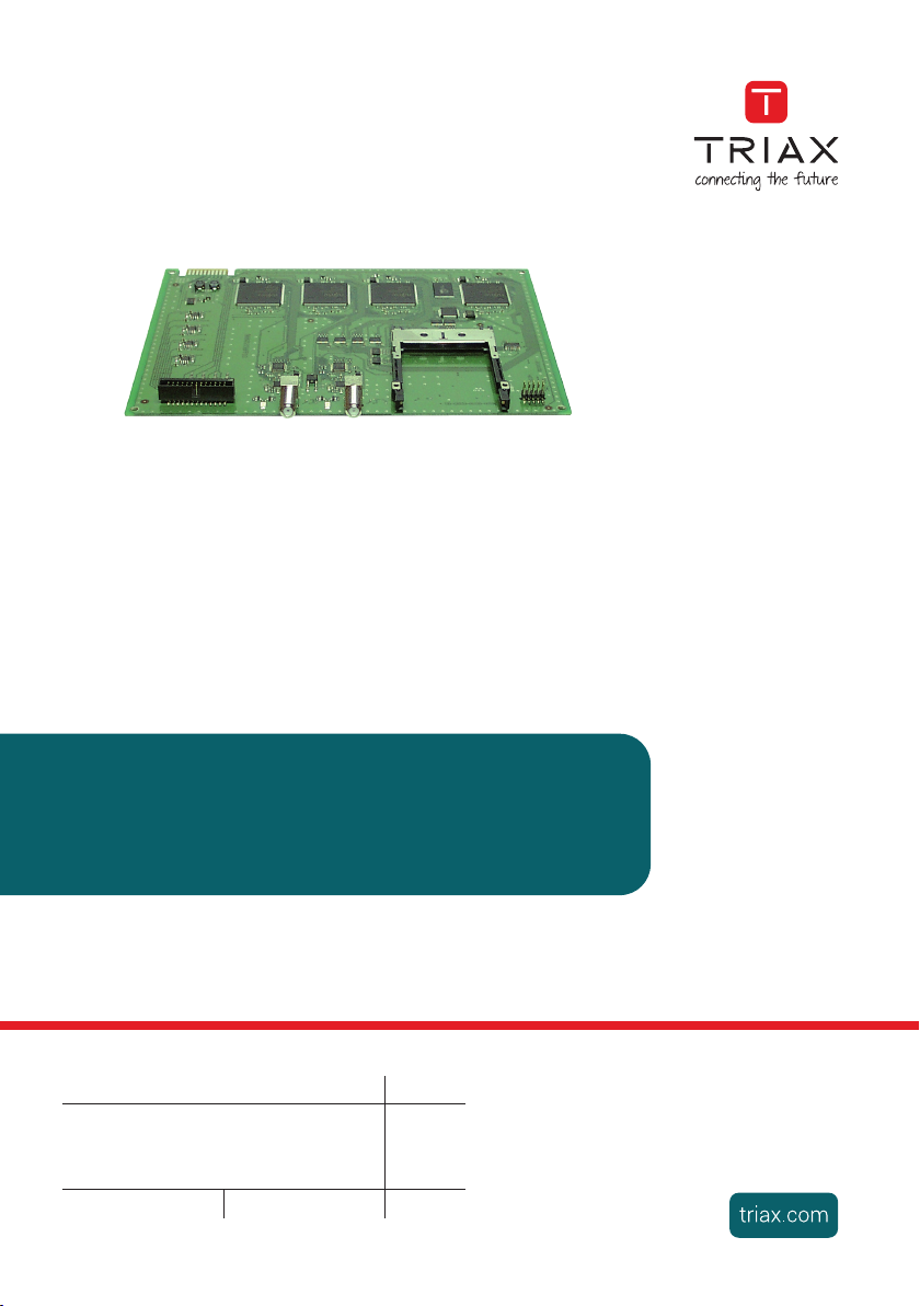
The module
CGS 470
, in the following called digital module, has a QPSK AV
converter which simultaneously converts four QPSK modulated channels into AV
signals using two SAT tuners. It is additionally equipped with a common interface, which enables the descrambling of up to 4 scrambled channels through a
single data stream when used in conjunction with a CA module and an appropriate smart card from a service provider.
The
digital
module
has two SAT inputs and one AV interface, through which the
decoded AV signals are fed to the corresponding modulator module. Components (e.g. LNB) which are connected upstream can be powered through the
SAT inputs.
The channel strips "A" "B", "C" and "D" can be individually programmed. This
means it is possible to select up to 4 channels from two transponders. Via
tuner "A" scrambled and unscrambled channels can be received. Tuner "D" is
prepared to receive unscrambled channels only.
The following tables show the possible allocations of the selectable number of
channels to the tuners.
For example, if three unscrambled channels from tuner "A" will be used, one
unscrambled channel from tuner "D" can be used. If , e.g. two unscrambled
channels from tuner "A" will be used, two unscrambled channels from tuner
"D" can be used.
Tuner "A" Tuner "D"
Quantity of unen-
crypted channels
3 1
2 2
1 3
For example, if four scrambled channels from tuner "A" will be used, no chan-
nel from tuner "D" can be used. If , e.g. two scrambled channels from tuner
"A" will be used, two unscrambled channels from tuner "D" can be used.
Tuner "A"
(encrypted
channels)
4 0
Quantity of
channels
- 5 - CGS 470
3 1
2 2
1 3
Tuner "D"
(unencrypted
channels)
Page 6
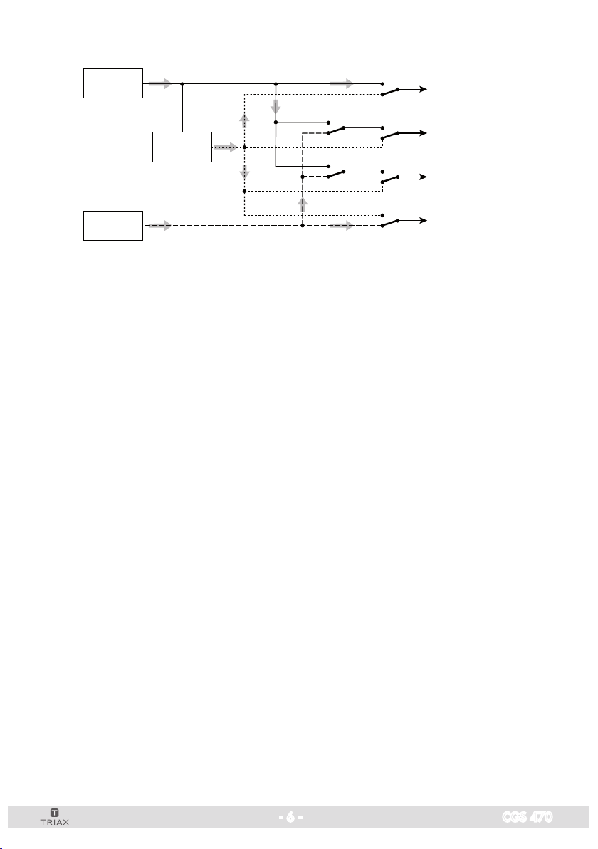
Signal transfer principle:
TUNER
"A"
CA module
TUNER
"D"
Channel strip "A"
Channel strip "B"
Channel strip "C"
Channel strip "D"
The prepared input signals are fed to the modulator module via the AV in-
terface. From there, they are fed to the HF output collector of the head-end
station, through which the level of the output signal can be adjusted via the
software in the head-end station.
The
digital module
operating software can be updated using a PC or notebook and the software "BE-Flash" via the 9-pin D-SUB socket on the head-end
station. You can find the current operating software for the
the software "BE-Flash"
and the current assembly instructions
digital module,
on the website
"www.triax.com".
This digital module is designed exclusively for use in the CSE 2800 head-end
station.
- 6 - CGS 470
Page 7
3 installation
– Ensure the head-end station is mounted so it will not be able to vibrate.
Avoid, for example, mounting the head-end station onto a lift shaft or any
other wall or floor construction that vibrates in a similar way.
– Before installing or changing a module, switch off the head-end station or
unplug the power cable from the mains power socket.
Take measures to protect against ESD!
• Open the housing of the head-end station in accordance with the assembly
instructions for the CSE 2800.
3.1 retr o fitting a Ca module
The digital module is equipped with a common interface. It allows you to
connect a CA module for various scrambling systems and service providers.
Scrambled channels can only be descrambled with a CA module suitable for
the scrambling system and the corresponding smart card. The smart card contains all the information for authorisation, descrambling and subscription.
Caution
– Check with the distributor or manufacturer of the CA module to be used
to ensure that it is suitable for descrambling several channels.
– The hardware and software of the module CGS 470 have been thoroughly
prepared and tested.
– Any changes made by program providers to the structures in the program
data might impair or even prevent this function.
– When working with a CA module, please read the corresponding operat-
ing manual from the respective provider.
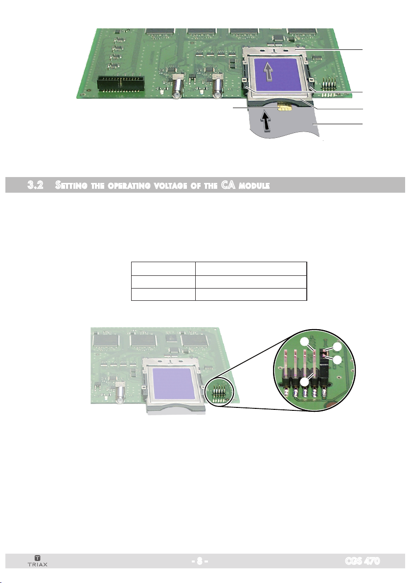
• Insert the smart card
smart card faces the thicker side (top) of the CA module (fig. 1).
• Push the CA module 2 without canting into the guide rails 4 of the common interface slot 5 according to the following picture and contact it to
the common interface.
- 7 - CGS 470
1 into the CA module 2 so that the chip 3
on the
Page 8
5
4
3
2
1
3.2 se tting th e ope ratin g vo ltage o f the Ca m odule
The CA modules can require different operating voltages.
• Set the required operating voltage by plugging the jumper to the respective
contacts:
Contacts Operating voltage
1 - 2 + 5 V (Factory default)
3 - 4 + 3.3 V
3
1
2
4
- 8 - CGS 470
Page 9
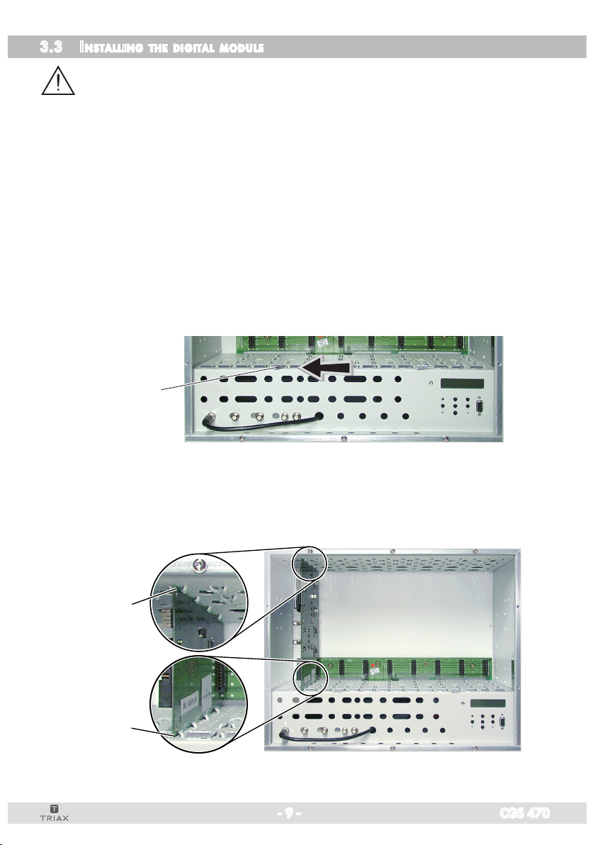
3.3 in sta lling t h e digital m o d u le
– If a CA module is used, check that the plug contacts of the CA module are
tightly seated in the terminal strip on the digital module and make sure there
is a reliable contact.
– Always position modules which belong together next to each other. The
digital module must be installed to the left of the modulator module.
– When installing the digital module, make sure that it is inserted in a long
numbered groove in front of a contact strip on the board at the rear wall of
the housing.
The shorter not numbered grooves without a contact strip on the board at
the rear wall of the housing are for add-on modules only.
• Open the housing of the head-end station in accordance with the assembly
instructions for the CSE 2800.
• Open the locking device 1 in the direction of the arrow.
1
• Insert the digital module in grooves A and B of an open slot left to the
associated modulator module
and gently slide it into the
head-end station
until it makes contact with the board on the rear wall.
B
A
- 9 - CGS 470
Page 10

• Install the appropriate modulator module.
—> Figure 5 shows the slots 1 (digital module) and 2 (modulator mod-
ule). The slot between them (without a contact strip on the board at
the rear wall of the housing) is for an add-on module only.
C
D
E
1
• After installing the modules close the locking device 1 in direction of the
arrow.
3.4 Co n n eCtin g the d i g ita l module
• Connect SAT-IF inputs C of the digital module to the preinstalled Fterminals in the rear wall of the head-end station via the cable inlets E using HF
cables made on-site (length approx. 80 cm) or if applicable to one of the
outputs of a retrofitted SAT-IF input distributor.
• Using the ribbon cable D to connect the AV output of the digital module to
the AV input of the modulator module.
- 10 - CGS 470
Page 11

4 the Control panel at a glanCe
4.1 menu i tems
Program the module using the buttons on the head-end station control unit. The
menus appear on the two-line display of the control unit.
The parameters and functions to be set are underlined.
You can use the button to select the following menu items:
– LNB oscillator frequency
– Tuner selection (channel strips "B", "C" and "D" only)
– Symbol rate
– Input frequency
– Station filter
– Audio stream selection
– Audio output level
– Stereo decoding / audio type selection
– Picture format signal (WSS)
– Test lines
– Teletext subtitle page
– Store
4.2 fu nCtions of th e Cont r ol panel b u t tons
M
S
– To move the cursor
– To adjust values and functions
– To store the programmed data
– To switch to the next menu
- 11 - CGS 470
Page 12

5 programming
5.1 pre par atio n
• Connect the digital module to a programmed modulator module.
—> For the programming of the output channels please read the assem-
bly instructions of the corresponding modulator module.
• Connect the test receiver to the HF output on the modulator module.
• Adjust the test receiver to the output channel of the channel strip to be set:
Digital module – channel strip "B" —> modulator module – channel strip "B",
Digital module – channel strip "C" —> modulator module – channel strip "C",
Digital module – channel strip "D" —> modulator module – channel strip "D".
• Switch on the modulator if necessary. For each modulator, there is a green
Digital module – channel strip "A" —> modulator module – channel strip "A",
LED which indicates if the modulator is switched on.
LED – Channel strip “A“
LED – Channel strip “B“
LED – Channel strip “C“
LED – Channel strip “D“
- 12 - CGS 470
Page 13

5.2 pr ogramming p r oCedure
Ein/On
SETUP
Bx 1A
ARD
M
Bx 1…
TUNER Line A
M
Bx 1…
10600 MHz
/
M
/
Bx 1…
27500
M
Bx 1…
11836 MHz
M
BE160
V 10
QUAD
V 18
INPUT
LNB
SYMBO L
FREQ
+0.2
Bedienhinweise
"blättert" Menüs vorwärts.
M
wählen die Eingabeposition
/
wählt Untermenü
stellen Werte ein,.
/
S
speichert alle Eingaben.
1 zeigt die Eingabeposition
Bx 1A
Böx 4
Bx 1B
C5-12 ,S3-2 4
C5-12 ,S3-2 4
ARD
TUNER Line D / Line A CA
/
Bx 1A M ENU
>
Infor matio n *)
/
/
/
/
Operating Hints
scrolls forward through the menu.
M
select the enter position.
/
selects a submenu.
set values and triggers actions.
/
S
saves all entries.
1 shows the enter position
TWIN- SAT
TWIN- SAT
QUAD
C07
C07
V 18
A
nur Kanalzug B, C, D
only channel strip B, C, D
1/6
/
/
*) Die angezeigte Information ist abhängig
M
vom verwendeten CA-Modul
The information displayed is dependent on
the CA module used
nur Kanalzug A mit CA-Modul
only channel strip A with CA module
nur Kanalzug A und D (INPUT TUNER Line D)
only channel strip A and D (INPUT TUNER Line D)
Bx 1…
01/06 + TV
Das E rste
/
Programmauswahl / Channel selection
M
Bx 1…
01 / 02 “d eu”
AUDIO
Das Menü wird nur bei Auswahlmöglichkeit
mehrerer Begleittöne angezeigt.
This menu is only displayed if several audio
/
streams are selectable.
M
Bx 1…
Level
AUDIO
-6 dB
/
-26 … 6 dB
M
Bx 1…
mpeg
AUDIO
DUAL norm
/
/
norm / swap
mpeg / VPS
M
- 13 - CGS 470
Page 14

M
/
/
M
Bx 1…
11836 MHz
FREQ
+0.2
/
/
Bx 1…
Das E rste
01/06 + TV
M
M
Bx 1…
Level
AUDIO
-6 dB
M
Bx 1…
mpeg
AUDIO
DUAL norm
M
M
Bx 1…
01 / 02 “d eu”
AUDIO
-26 … 6 dB
/
/
/
Bx 1…
27500
SYMBO L
/
/
M
Das Menü wird nur bei Auswahlmöglichkeit
mehrerer Begleittöne angezeigt.
This menu is only displayed if several audio
streams are selectable.
*) Die angezeigte Information ist abhängig
vom verwendeten CA-Modul
The information displayed is dependent on
the CA module used
nur Kanalzug A und D (INPUT TUNER Line D)
only channel strip A and D (INPUT TUNER Line D)
nur Kanalzug A mit CA-Modul
only channel strip A with CA module
norm / swap
mpeg / VPS
/
/
Programmauswahl / Channel selection
Bx 1…
Lette r
Bx 1…
WSS o n
Bx 1…onTESTL INES
Bx 1…
off
Bx 1…
S => S TORE
VIDEO
M
VIDEO
TXT o n
M
M
SUBTI TLE
/
M
off / txt / dvb / bla ck
MEMORY
S
Letter / 16:9
/
/
on / off
/
on / off
/
Bx 1…
txt
M
SUBTI TLE
150 west
/
M M
/
west / eas t 0…63
CAN CEL
Bx 1…
dvb
SUBTI TLE
– –
nur w enn U ntert itel
verfü gbar sind:
Sprac he au swähl en
only if su btitl es are
avail able:
selec t lan guage
/
/
Bx 1…
black
SUBTI TLE
M
40/10
/
/
A
- 14 - CGS 470
Page 15

5.3 pr ogramming t h e digital m odule
Notes:
– Entries are saved by pressing the button.
—> You will be returned to "Selecting the module/channel strip".
– The programming process can be cancelled by pressing and holding the
button.
—> You will be returned to "Selecting the module/channel strip".
• Switch on the head-end station.
—>
The display shows "SETUP BE160" and the software
head-end station (e.g. V 10).
—> The output level of the output collector can be adjusted in the "SET-
UP" menu (see CSE 2800 assembly instructions).
version of the
Ein/On
SETUP
- 15 - CGS 470
BE160
V 10
Page 16

se l eCtin g the m o dule / Channel s trip
• Press repeatedly if necessary to select the particular module (Bx ...) or
channel strip
"A", "B", "C" or "D"
to be programmed.
Bx 1A
Böx 4
Bx 1A
ARD
QUAD
V 18
Bx 1B
C5-12,S3-24
C5-12,S3-24
ARD
• Press the button to activate the channel strip.
—> The display shows, e.g., the "Bx 1A QUAD" menu.
"Bx" indicates the slot
"1" indicates slot no. 1
"A" indicates channel strip "A"
"ARD" name of the selected channel
"V 18" software version of the module
• Press the button:
Channel strip B, C or D:
—> The "Tuner" – "INPUT TUNER" menu is activated.
Channel strip A:
—> The "LNB oscillator frequency" – "LNB" menu is activated (page 17).
TWIN-SAT
TWIN-SAT
QUAD
C07
C07
V 18
tuner
Select the tuner in this menu out of which demodulated data stream a channel
has to be used.
Bx 1D
TUNER Line A
—> This menu is only displayed in channel strips B, C and D.
- 16 - CGS 470
INPUT
Page 17

• Using buttons select the tuner:
For Channel strips "B" and "C": "TUNER Line A" or "TUNER Line D",
For Channel strip "D": "TUNER Line D" or "TUNER Line A CA"
• Press the button.
Channel strip A / Channel D with setting "Tuner Line D":
—> The "LNB oscillator frequency" – "LNB" menu is activated.
Channel strip B or C / Channel strip D with setting "Tuner Line A CA":
—> The "Station filter" menu is activated (page 20).
lnb os Cillat o r fre q u e nCy
—> This menu is only displayed in channel strip A / channel strip D with
setting "Tuner Line D".
Bx 1A
10600 MHz
• Using the
LNB
>
Bx 1A ME NU
Information *)
1/6
buttons, move the cursor under the digit of the oscillator
frequency to be set.
• Use the
buttons to set the oscillator frequency of the LNB being used
• Press the button.
—> This menu is only displayed in channel strip A if a CA modul is in use.
—> The "CA module, card information" – "MENU" is activated.
—> *) The information shown in the display is dependent on the CA
module used.
- 17 - CGS 470
.
Page 18

Ca modul e, Card in format i o n
A menu has been provided for these settings, which is displayed on your TV
screen. The menu varies according to which CA module is used. For this reason, please refer to the operating manual of your particular CA module. The
relevant information is shown on the display of the head-end station.
• Use to select a menu item on the screen.
• Activate the menu item with .
• Select the required function with the buttons.
• Press the button to store the settings.
• Press the button.
—> Input symbol rate" – "SYMBOL" menu is activated.
in put s ymbo l rat e
—> This menu is only displayed in selection channel strip A and selec-
tion channel strip D with setting "Tuner Line D".
The symbol rate of the satellite transponder can be found in the current trans-
ponder tables of the various satellite
respective service
provider.
trade magazines or on the website of the
•
Using the
Bx 1A
27500
buttons, move the cursor under the digit of the symbol rate
SYMBOL
displayed to be set.
• Use the
buttons to set the desired symbol rate.
• Press the button.
—> The "Input frequency" – "FREQ" menu is activated.
- 18 - CGS 470
Page 19

in put f requen Cy
—> This menu is only displayed in selection channel strip A and selec-
—> Once the HF receiver has synchronised to the input signal, any
—> If a question mark "?" appears in the second line of the display,
tion channel strip D with setting "Tuner Line D".
offset to the target frequency is displayed in MHz, e.g. "+ 0.2".
there is no input signal present. Check the configuration of the antenna system and head-end station as well as the preceding settings
of the module in question.
•
Using the
displayed
• Use the
•
Press the buttons to adjust the input frequency displayed so that the
frequency offset amounts to less than 1MHz.
Bx 1A
11836 MHz
buttons, move the cursor under the digit
FREQ
+0.2
of the frequency
to be set.
buttons to set the input frequency.
—>
A status LED indicates the quality of the received transport stream::
Status LED
Tuner ”A“
Status LED
Tuner ”D“
LED indicator Signal quality
Green Good
Orange
Red no signal
Poor
• Press the button.
- 19 - CGS 470
Page 20

—> The "Station filter" menu is activated.
station f i lte r
In this menu, select the channel from the data stream that is to be made avail-
able through this channel strip.
If the error message "SERVICE no transponder" appears, no input signal
is present. In this case, you should check the previous settings as well as the
configuration of the SAT antenna system.
If the "scanning ..." message appears on the display, the table of received
channels is being read. Please wait until this process is finished.
As soon as the station filter has found all of the TV or radio channels, the corre-
sponding data appears in the display of the
head-end station
.
Bx 1A
Das Erste
Meaning of the indicators shown in this example:
"01/06" The first of a total of six channels has been activated.
" + " The audio stream for the current TV channel is avail-
"TV" The data on the display corresponds to a TV channel.
"Das Erste" Channel name
Other possible indicators:
"RA" The data on the display corresponds to a radio chan-
" + " The audio stream for the current TV channel is avail-
" * " A star indicates that this TV or radio channel is scram-
—> For radio channels, the background of the screen of the connected
TV or test receiver is darkened.
—> If a service number (e.g. "SERVICE 131") appears instead of "TV" or
"RA", this indicates that an unnamed station or an undefined data
stream is being received.
01/06 + TV
able in several languages.
nel.
able in several languages.
bled. To enable the channels, a CA module and a
s
mart card from the respective service provider
required.
are
- 20 - CGS 470
Page 21

• Select the desired TV or radio
channel
with the buttons.
• Press the button.
—> If the selected channel is broadcast with two or more audio streams,
the "Audio stream for a TV channel" – "AUDIO" menu will appear.
Otherwise the "Volume level" –
(see page 21).
"AUDIO Level" menu is activated
au dio st r ea m fo r a t v Channel
This menu only appears if the selected channel is broadcast with two or more
audio streams (languages). In this menu, select the desired audio stream from
the transport stream.
Bx 1A
01 / 02 “deu”
AUDIO
• Use the buttons to select the audio stream you want.
• Press the button.
—> The "Volume level" – "AUDIO Level" menu is activated.
vol ume l evel
In this menu, you can balance unequal volume levels of TV and radio stations
in the various channel strips.
Bx 1A
Level
AUDIO
-6 dB
• Set the volume level to the same level as the levels of the other output channels using the buttons (+6dB … -26dB), if necessary.
• Press the button.
—> The "Identification of the stereo / dual tone" – "AUDIO" menu is
activated.
- 21 - CGS 470
Page 22

id e ntifi Cati on of t h e ste reo / dual tone
In this menu, you can select whether the stereo audio identification is decoded
from the VPS data or from the MPEG data stream. Further you can swap the
languages on TV stations with dual tone.
Bx 1A
mpeg
AUDIO
DUAL norm
• Using the buttons, select the data stream from which the identification
("mpeg" or "VPS") to be used.
•
Use the buttons to position the cursor under the dual tone code "DUAL
…" to be set.
• Use the buttons to switch between "Dual norm" or "Dual swap" audio
streams for dual tone TV channels.
• Press the button.
—> The "Selecting the picture format" – "VIDEO" menu is activated.
se l eCtin g the p i Cture format
TV programmes are transmitted in accordance with DVB Standard in picture format
4:3 or 16:9. The factory setting "Letterbox" should be retained in normal circum-
stances, as 4:3 TVs are also supported in this case. The "16:9" setting should only
be selected if all of the TVs connected to the head end are 16:9 capable. The set-
tings are only effective with TV programmes with the picture format "16:9"!
"Letterbox": Black bars at the top and bottom edge of the screen (so that
the picture is not distorted at 4:3 TVs).
"16:9": In the case of TVs with the picture format 4:3, the picture con-
tent is vertically "stretched" (e.g. faces appear longer).
Bx 1A
Letterbox
• Press the buttons to set the picture format wished (
VIDEO
"Letterbox"or"16:9"
• Press the button.
—> The "Picture format, Teletext mode" – "VIDEO" menu is activated.
- 22 - CGS 470
).
Page 23

pi Cture f orm at signal , te letex t mode
Bx 1A
10600 MHz
LNB
>
A
Bx 1A
C5-12,S3-24
TWIN-SAT
C07
Böx 4
C5-12,S3-24
TWIN-SAT
C07
Bx 1B
WDR Köln
QUAD
V 1
Bx 1A
Das Erste
QUAD
V 1
Bx 1A ME NU
Information *)
1/6
M
M
/
/
/
/
M
Bx 1A
11836 MHz
FREQ
+0.2
/
/
Bx 1A
Das Erste
01/07 + TV
M
M
Bx 1A
Level
AUDIO
0 dB
M
Bx 1A
mpeg
AUDIO
DUAL norm
M
M
Bx 1A
01 / 02 “deu”
AUDIO
-26 … 6 dB
Bx 1A
WSS off
VIDEO
TXT on
/
/
/
/
Bx 1A
27500
SYMBOL
/
/
M
Das Menü wird nur bei Auswahlmöglichkeit
mehrerer Begleittöne angezeigt.
This menu is only displayed if several audio
streams are selectable.
*) Die angezeigte Information ist abhängig vom verwendeten CA-Modul
The information displayed is dependent on the CA module used
norm / swap
on / off
mpeg / VPS
/
/
/
/
M
on / off
Programmauswahl / Channel selection
If problems with the automatic picture format switchover (e.g. 4:3, 16:9, Letter-
In addition you can
•
• To activate/deactivate teletext mode,
box) arise with the connected devices, you can switch "off" the Wide-ScreenSignaling (WSS) in this menu.
To activate/deactivate WSS, use the buttons to select "off" or "on".
cursor under teletext mode "
teletext "off" or "on".
activate or deactivate the teletext mode.
Bx 1A
WSS on
TXT on
VIDEO
TXT on
use the
" and use the
buttons to position the
buttons to switch the
• Press the button.
aCtivati ng te s t lines
For specific applications test lines can be inserted in the teletext in this menu.
—> The "Activating test lines" – "TESTLINES" menu is activated.
• Using the
• Press the button.
—> The "Teletext subtitle pages and Standard" – "SUBTITLE" menu is
buttons switch the test lines "on" and "off"
activated.
Bx 1A
off
TESTLINES
- 23 - CGS 470
Page 24

tele text s ubtit l e pages a n d standa rd
This menu allows subtitles (transmitted in teletext or DVB data stream) to be
displayed directly in the channel or parts of the screen to be masked by a
black bar. Using the
buttons, the submenus can be selected. With set-
ting "SUBTITLE - off" subtitle function is switched off.
M
Bx 1A
off
SUBTI TLE
/
M
off / txt / dvb / bla ck
Bx 1A
txt
SUBTI TLE
150 west
/
M M
/
west / eas t 0…63
Bx 1A
dvb
SUBTI TLE
– –
nur w enn U nterti tel
verfü gbar sind:
Sprac he au swähle n
only if su btitle s are
avail able:
selec t lan guage
Bx 1A
black
/
/
SUBTI TLE
M
40/10
/
/
aCtivati ng te letext s u btit l e pages a n d set ti ng th e sta ndar d
This menu allows subtitles transmitted in teletext to be displayed directly in the
channel.
To display the characters for Western ("west") or Eastern ("east") European
languages, the corresponding character set can be selected.
• U
• U
• U
sing the
sing the
use
sing the
buttons select the submenu "SUBTITLE - txt".
Bx 1A
txt
buttons select the digit of the page number to be set. Then
to set each of the three digits.
buttons select the
SUBTITLE
150 west
teletext standard setting, e.g. "west" and
use to select the teletext standard "west" or "east".
• Press
the
button to activate these settings and to leave the
subtitle functions" menu
"Setting the
.
—> The "Storing data" – "MEMORY" menu is activated (see page 26).
- 24 - CGS 470
Page 25

aCtivati ng dvb sub t itle pag es
Bx 1A
black
SUBTITLE
40/10
This menu allows subtitles transmitted in a DVB data stream to be displayed
directly in the channel.
The language of the subtitles can be selected.
• U
• U
sing the
sing the
buttons select the submenu "SUBTITLE - dvb".
buttons select "– –" and select the language you want using
the buttons
—> This selection is only possible if subtitles are available.
• Press
the
button to activate these settings and to leave the
subtitle functions" menu
—> The "Storing data" – "MEMORY" menu is activated (see page 26).
Bx 1A
dvb
SUBTITLE
– –
.
.
bl aCk b ar
This menu allows to mask a part of the screen by a black bar.
position and the height can be adjusted.
• U
sing the
buttons select the submenu "SUBTITLE - black".
Bx 1A
black
SUBTITLE
40/10
"Setting the
The vertical
• U
- 25 - CGS 470
sing the
buttons select
the setting of
"vertical position / height of the
bar" and set the value you want using the buttons
• Press
the button to activate these settings and to leave the
subtitle functions" menu
—> The "Storing data" – "MEMORY" menu is activated (see page 26).
.
.
"Setting the
Page 26

stori ng data
Bx 1A
S => STORE
MEMORY
S
M
CANCEL
• All programmed data is saved by pressing the button. Then you will be
returned to the menu item "Selecting the module / channel strip" (page 16).
—> By pressing the button, you will be returned to the menu item "Se-
lecting the module / channel strip" without
data.
saving the programmed
- 26 - CGS 470
Page 27

6 fi n a l proCedures
After installing the head-end station, upgrading accessories or installing mod-
ules it is necessary to tighten all cable connections, cable terminals and cover
screws in order to maintain compliance with current EMC regulations.
• Securely tighten the cable connections (F connectors) using an open-ended
spanner (spanner gap 11 mm).
• Test the output level of the output collector according to the CSE 2800 assembly instructions and set the output level required for the cable system.
• Mount the base plate and the front cover (see CSE 2800 assembly instructions).
- 27 - CGS 470
Page 28

For further information
and updated manuals go to
Copyright © 2016 TRIAX. All rights reserved. The TRIAX Logo and TRIAX, TRIAX Multimedia are
registered tr ademarks or trademarks of the TRIA X Company or its affiliates.
All specificat ions in this guide are subject to change without further notice.
TRIAX A/S | Bjørnkærvej 3 | DK-8783 Hornsyld | Denmark
 Loading...