

Page 1
A
CLASS
KLASSE
Head-End Receiver Modulator
CCS 1231
CCS 1233
CCS 1234
CCS 1235
A
KLASSE
CLASS
Art. No. 325110 / 325111 / 325112 / 325113 GB
Assembly Instructions
TRIAX - your ultimate connection
Page 2

- 2 -
Contents
1 Safety regulations .......................................................................................................3
2 General information ....................................................................................................4
2.1 Package contents ..........................................................................................4
2.2 Technical data ..............................................................................................4
2.3 Description ..................................................................................................5
2.4 Display of the software version .......................................................................6
2.5 Scope of application .....................................................................................6
3 Assembly ....................................................................................................................7
3.1 Installing the Cassette ....................................................................................7
3.2 Connecting the Cassette ................................................................................8
4 The control panel at a glance.......................................................................................8
4.1 Menu items ..................................................................................................8
4.2 Control panel ...............................................................................................9
5 Programming .............................................................................................................9
5.1 Preparation ..................................................................................................9
5.2 The menus at a glance ................................................................................10
5.3 Programming the Cassette ...........................................................................12
5.3.1 Setting the output level (channel strips)
5.3.2 Setting the output channel ............................................................ 13
5.3.3 Setting the input frequency (transponder frequency) .......................... 13
5.3.4 Modulator menu......................................................................... 14
Setting the modulation depth (residual carrier) ................................. 14
Setting the picture/sound spacing.................................................. 15
5.3.5 Setting the IF bandwidth (threshold) ............................................... 15
5.3.6 Sound settings ........................................................................... 16
5.3.6.1 Selecting audio type and frequency (reception) .................. 16
5.3.6.2 “STEREO” audio type .................................................... 16
5.3.6.3 Audio setting “autom. V:STEREO” .................................. 17
5.3.6.4 Audio setting “manual V: STEREO”: ................................ 17
5.3.6.5 Switching audio channel 1/audio channel 2 ..................... 18
5.3.6.6 “MAIN” audio type ...................................................... 19
5.3.6.7 “SubMONO” audio type .............................................. 20
5.3.7 Adjusting the volume .................................................................. 20
5.3.8 Saving settings ........................................................................... 20
5.3.9 Setting channel strip “B” .............................................................. 20
6 Blanking of the video signal ......................................................................................21
............................................ 12
7 C band reception ......................................................................................................22
8 Channel and frequency tables ...................................................................................23
- 2 -
Page 3

- 3 -
1 Safety regulations
Important
• Assembly, installation and servicing must be carried out by an authorised
electrician.
• Switch off the operating voltage before starting assembly or service work or
pull out the mains plug.
• Install the system …
- in a dust-free, dry environment,
-
so that it is protected from moisture, vapours, splashing water and dampness,
- somewhere protected from direct sunlight,
- away from the immediate vicinity of heat sources,
- at an ambient temperature of < 50 °C.
• Make sure the device is adequately ventilated.
Do not cover the ventilation slots!
• Avoid short circuits!
• No liability is accepted for damage caused by a faulty connection or inexpert
handling.
• Observe the relevant standards, regulations and guidelines on the installation
and operation of antenna systems.
• Earth the SAT receiver using the equipotential bonding rail in accordance with
DIN EN 50083 and VDE 0855.
• Do not perform installation and service work during thunderstorms.
Take measures to prevent static discharge when working on the device!
Electronic devices should never be disposed of in the household rubbish.
In accordance with directive 2002/96/EC of the European Parliament
and the European Council from January 27, 2003 which addresses old
electronic and electrical devices, such devices must be disposed of at a
designated collection facility. At the end of its service life, please take
your device to one of these public collection facilities for proper disposal.
- 3 -
Page 4

- 4 -
2 General information
2.1 Package contents
1 Cassette CCS 1231 or CCS 1233 or CCS 1234 or CCS 1235
1 HF connection cable
1 CD (assembly instructions)
2.2 Technical data
The following EU directives are met:
73/23/EEC, 89/336/EEC
The product fulfills the guidelines and standards for CE labelling.
SAT input:
Frequency range: 950 … 2150 MHz
Frequency raster: 1 MHz
Fine tuning increment: 125 kHz
Level range: 57 dBµV … 80 dBµV
IF bandwidth: 3-stage broadband reduction (threshold)
Video
Frequency range: 5 Hz … 5 MHz
Deviations: automatic, 14 … 26 MHz
Polarity: can be set, positive/negative
Audio
Frequency range: 20 Hz … 15 kHz
Audio frequency range: 5 MHz … 9.77 MHz
Sound IF bandwidth: can be set, main: 280 kHz/sub: 130 kHz
De-emphasis: can be set, main: 50 µs/75 µs/J 17
Mono/stereo/dual (two-channel) with VPS code
HF output:
Fine tuning range: ± 4 MHz
Fine tuning increment: 62.5 kHz
Signal to noise: typ. 56 dB
Output level: 96 – 104 dBµV
Output impedance: 75 Ω, nominal
CCS 1231
Modulator channels channel strip A: C2 … C4
Frequency range: 48.25 MHz … 62.25 MHz
Channel raster: PAL CCIR standard B
Modulator channels channel strip B: S3 … S24 including C5 … C12
- 4 -
Page 5

- 5 -
Modulator channels channel strip B: S3 … S24 including C5 … C12
Frequency range: 119.25 MHz … 327.25 MHz
Channel raster: PAL CCIR standard B/G
CCS 1233
Channels: S3 … S24 including C5 … C12
Frequency range: 119.25 MHz … 327.25 MHz
Channel raster: PAL CCIR standard B/G
CCS 1234
Channels: S21 … S41
Frequency range: 303.25 MHz … 463.25 MHz
Channel raster: PAL CCIR standard G
CCS 1235
Channels: C21 … C69
Frequency range: 471.25 MHz … 855.25 MHz
Channel raster: PAL CCIR Standard G
Connections:
SAT inputs: 1 IEC socket (female), 2nd input prepared
HF output (modulator): 1 IEC socket, female
Connection strip (10-pin): Supply voltages, control circuits
Socket RS 232: Serial interface (Sub-D, 9-pin)
2.3 Description
These twin-SAT cassettes enables the conversion of two TV satellite signals
of the same polarisation (horizontal or vertical) from the 1st SAT IF level
(950-2150 MHz) to the TV ranges band I to band V.
Each Cassette contains 2 channel strips with identical circuits. These are indicated in the display by Bx A or Bx B. The SAT signal transmitted via the SAT input
passes the SAT tuner, the video and stereo audio signal processing units and is
sent on to the combiner via a CCIR modulator. The combiner links the channel
strip A signal to the signal at channel strip B and transmits the signal via the HF
output socket of the HF bus bar. The signal can be set using the corresponding
level regulator (max. –20 dB). All other settings are made using the keypad of
the control unit of the head end.
After switching on the head end, the software version of the control unit is
displayed briefly in the two-line LC display. Approx. five minutes after the last
button has been pressed, the display switches off automatically or the software
version of the control unit is displayed.
- 5 -
Page 6

- 6 -
2.4 Display of the software version
• Keep any two keys on the control unit of the head end pressed simultaneously until the display goes dark and the software version, e.g. “V.30 ”, is
displayed.
Important:
The head end requires a control unit with the V.27 software version or higher to
control these cassettes. For lower software versions, the software of the control
unit must be updated.
2.5 Scope of application
The cassettes are designed for use in the following head ends:
– CSE 3312
– CSE 3319
- 6 -
Page 7

- 7 -
3 Assembly
3.1 Installing the Cassette
Warning
• Pull the mains plug out of the head end of the mains socket before inserting or replacing cassettes.
• Unscrew the screws 1 from the bracket in the head end.
• Insert the Cassette into a free slot and push it into the housing.
• Align the Cassette and gently make it contact with the connections of the
circuit board and the HF bus bar.
• Fasten the Cassette with the 1 screws.
1
0°
- 7 -
1
Page 8
- 8 -
3.2 Connecting the Cassette
SAT IF input
• Connect the input cable to the SAT IF input.
• Connect the head end to the mains power supply.
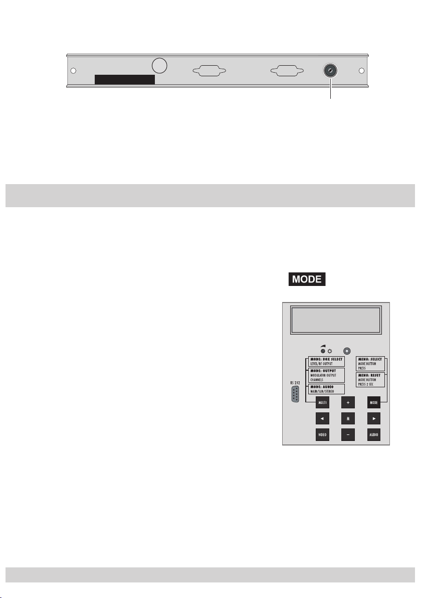
4 The control panel at a glance
4.1 Menu items
The cassettes can be programmed using the keys on the head end control unit.
The two-line display of the control unit then shows the menus.
You can select the following main menu items with the button:
– Cassette and channel strip
– Output channel, fine tuning (offset)
– Input frequency, fine tuning
– Modulator setting
– IF bandwidth
– Audio types
– Volume adjustment
- 8 -
BE–Remote V.30
please wait . . .
Page 9

- 9 -
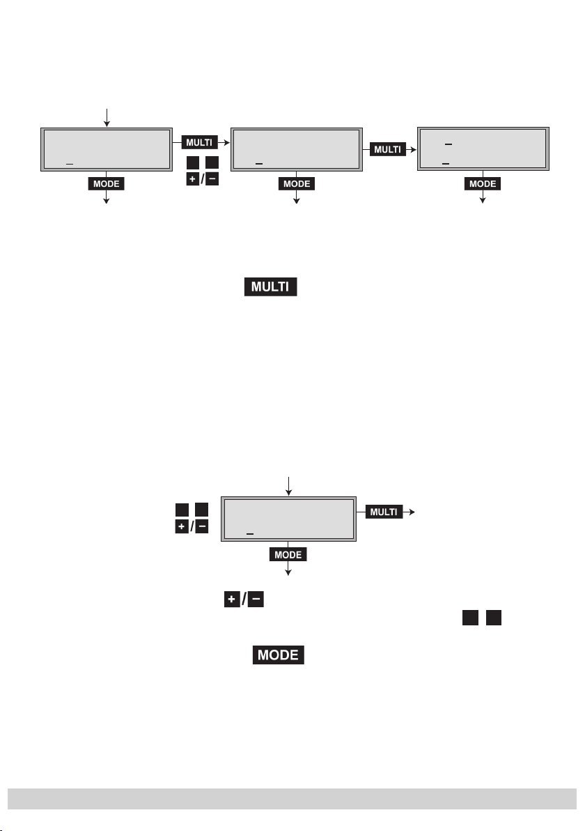
4.2 Control panel
You can individually select the menus and menu items step-by-step using the
keypad of the head end:
–
–
◀
– set values, initiate actions
– selects sub-menus
M
–
– The parameters to be set are underlined (cursor).
scrolls forward through the menu
select parameters in the menus
▶
/
saves all entries
5 Programming
The following examples show how to program the Cassette CCS 1233.
5.1 Preparation
• Connect the test receiver to the HF output of the head end.
• Set the output channel of the Cassette (see page 13) and adjust the test receiver to this channel.
• Switch on the modulator if necessary.
• Balance the output levels of the channel strips “A” and “B” if the difference in
level is ≥ 1 dB (see page 12).
• Measure the output level of the analogue cassettes and, if necessary, tune
them to a uniform output level.
- 9 -
Page 10

- 10 -
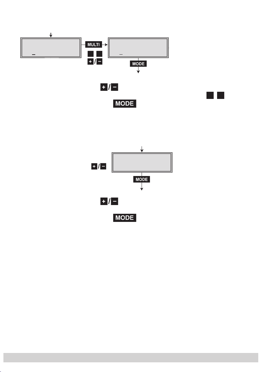
5.2 The menus at a glance
The standard menu shows the programming sequence using the example of
channel strip “A”. Programming for channel strip “B” is done in the same
way.
Ein / On
Bx 1 … n
◀
▶
/
BE–Remote
please wait …
t > 10 s
Bx 1A
C5-12
Bx 1A
C12
Bx 1A
1090.0 MHz
Bx 1A
PAL
TWIN-SAT
OUTPUT:
DECODER:
V. 3 0
C12
INPUT:
M
Bx 1A
Level HF Out
TWIN-SAT
0 … – 7 dB
0
t > 2 s
n
I
t > 2 st > 2 s
▶
▶
Bx 1A
C12 Fine
Bx 1A
Modulator:
Bx 1A
Depth:
OUTPUT
MODULAT:
MODULAT:
on
normal
+ 63…– 64
0
on / off
normal … –10%
Bx 1A
IF wide
TUNER:
Bx 1A
Pic/Snd
wide / narrow / DX
- 10 -
MODULAT:
normal
–1…normal … +2 dB
Page 11

- 11 -
◀
Bx 1A
▶
/
7.02 MHz
STEREO
Bx 1A
autom.
manuell
Bx 1A
Dual
Dual
Bx 1A
T1 7.02
5,5 MHz 5,74 MHz
T1 7,02 MHz 7,20 MHz
T2 7,20 MHz 7,02 MHz
AUDIO-IN:
VPS:
V: STEREO
autom.
AUDIO-OUT:
Stereo
Change:
T2 7.20
Bx 1A
◀
7.02 MHz
▶
/
Bx 1A
Bx 1A
Deemphasis
Deemphasis
50us
Bx 1A
7.02 MHz
SubMONO
AUDIO-IN:
MAIN
AUDIO-IN:
AUDIO-IN:
50μs, 75μs
J17
◀
▶
/
Bx 1A
Vol.: –
AUDIO-OUT:
+
M
- 11 -
Page 12

- 12 -
5.3 Programming the Cassette
• Switch on the head end.
—> The processor reads the cassettes‘ data (approx. 10 seconds).
—> The display shows the software version (e.g. V.30).
Ein / On
Bx 1 … n
BE–Remote
please wait …
t > 10 s
Bx 1A
C5-12
TWIN-SAT
5.3.1 Setting the output level (channel strips)
V. 30
C12
Bx 1A
M
Level HF Out
TWIN-SAT
0 … – 7 dB
0
—> The display shows e.g. the menu “Bx 1A TWIN-SAT”.
“Bx” stands for Cassette (box),
“1” for Cassette 1,
“A” for channel strip A.
• Select the Cassette to be programmed (box no.) by repeatedly pressing the button
• Press the button.
—> The “LEVEL HF OUT:” menu appears on the display.
• Select the channel strips “A” or “B” and by pressing
adjust the higher output level of one channel strip to the
lower output level of the other channel strip by increments
of “0” to “–7” dB.
.
• To save the channel strip settings:
press the M button.
Repeat the adjustment for other cassettes and channel
strips, if required.
• Press the button.
—> The “OUTPUT” menu is activated.
- 12 -
Page 13

- 13 -
5.3.2 Setting the output channel
Bx 1A
C12
OUTPUT:
• By pressing
t > 2 s
▶
Bx 1A
C12 Fine
OUTPUT
+ 63…– 64
0
, set the desired output channel.
—> The channel range that can be set depends on the
type of Cassette used.
Frequency offset (fine tuning)
Important: Only change the frequency offset in exceptional
circumstances and if there is a well-founded reason for
doing so, since once you have changed it, all connected
televisions of the cable system must be adjusted to match it
by means of corresponding fine-tuning corrections.
• Press and hold down the
▶
button until “0” also appears
on the display.
• Set the frequency offset (+63 … –64) with the buttons.
• Press the button.
—> The “INTPUT” menu is activated.
5.3.3 Setting the input frequency (transponder frequency)
In this menu with VPS code, the name of the station is dis-
played instead of “INPUT”. The VPS code is not supported
by all stations!
◀
/
Bx 1A
▶
1090.0 MHz
INPUT:
• Press
—> Change the position of the cursor with
n
I
to set the input frequency.
.
◀
▶
/
- 13 -
Page 14

- 14 -
The display “ I ” is for helping to set the input frequency.
That does not mean that a visual check is unnecessary.
n
Reception frequency is too low
Reception frequency is ideal
Reception frequency too high
• Press the button.
—> The “DECODER” menu appears in the display.
Bx 1A
PAL
• Press and hold down the
button until
▶
“MODULAT: Modulator” appears in the display.
5.3.4 Modulator menu
DECODER:
t > 2 st > 2 s
▶
Bx 1A
Modulator:
MODULAT:
on
on / off
• By pressing the buttons, switch the modulator (HF
output) off or on (“off” or “on”).
• Press the button.
—> The display shows “MODULAT: Depth:”.
Setting the modulation depth (residual carrier)
If the sound drones due to the content of the picture, lower
the modulation depth.
Bx 1A
Depth:
MODULAT:
normal
normal … –10%
• Press to set the modulation depth (“normal” or
“-5 %” or “-10 %”).
- 14 -
Page 15

- 15 -
• Press the button.
B
—> The display shows “MODULAT: Pic/Snd”.
Setting the picture/sound spacing
In the event of moiré interference, the 5.5 MHz audio fre-
quency can be set.
5.3.5 Setting the IF bandwidth (threshold)
Bx 1A
IF wide
Bx 1A
Pic/Snd
MODULAT:
normal
–1…normal … +2 d
• Press to set the attenuation of the audio frequency.
(“–1” dB, “normal”, “+1” dB, “+2” dB).
• Press the button.
—> The “TUNER IF” menu appears in the display.
The IF bandwidth should only be changed in the event of
bad reception conditions.
TUNER:
wide / narrow / DX
• Use to set the value “wide”/“ narrow”/ “ DX” for the
best picture and sound.
• Press the button.
—> The “AUDIO-IN” menu appears in the display.
- 15 -
Page 16
- 16 -
Bx 1A
7.02 MHz
AUDIO-IN:
STEREO
▶
◀
/
▶
◀
/
5.3.6 Sound settings
5.3.6.1 Selecting audio type and frequency (reception)
Bx 1A
7.02 MHz
STEREO
“STEREO”audio type
AUDIO-IN:
Page 16
Bx 1A
◀
7.02 MHz
▶
/
“MAIN” audio type
Page 19
AUDIO-IN:
MAIN
Bx 1A
7.02 MHz
SubMONO
“SubMONO” audio type
Page 20
AUDIO-IN:
• Use the button to select the audio type:
“STEREO”/ “ MAIN”/“ SubMONO”
5.3.6.2 “STEREO” audio type
If the “STEREO” audio type is selected, the lower audio fre-
quency of the corresponding stereo pair 7.02/7.20 MHz
or 7.38/7.56 MHz etc. is set. The upper audio frequency
is automatically received using a frequency that is 180 kHz
higher.
• Use to set the audio frequency.
◀
▶
—> Change the position of the cursor with
/
.
• Press the button.
—> The display shows the “VPS” menu.
Note:
If “autom.” and “NO IDENT” are displayed, then the sta-
tion does not transmit any VPS code. In this case select the
display “manuell” (manual).
- 16 -
Page 17

- 17 -
Bx 1A
autom.
autom.manuell
VPS:
V: STEREO
• Use to select the setting “autom.” or “manuell” .
5.3.6.3 Audio setting “autom. V:STEREO”
• Press the button. The display shows the
“AUDIO-OUT: Vol.:” menu.
• Adjust the volume (page 20).
• Save the settings (page 20).
5.3.6.4 Audio setting “manual V: STEREO”:
• Press the button. The display shows the
menu “AUDIO-OUT Stereo” or “Dual”.
Bx 1A
Dual
Dual
AUDIO-OUT:
Stereo
manuell
autom.
• Use to select “Stereo” for stereo sound or “Dual”
for 2-channel sound.
—> “Stereo” audio setting
• Press the button.
—> The display shows “AUDIO-OUT: Vol.:”.
• Adjust the volume (page 20).
• Save the settings (page 20).
- 17 -
Page 18

- 18 -
—> “Dual” audio setting:
Select “Dual” for stations that use the audio frequen-
cies for transmitting different languages.
• Press the button.
The display shows the “Change” menu.
5.3.6.5 Switching audio channel 1/audio channel 2
In this menu you have the option of assigning the lower
audio frequency (7.02 MHz/7.20 MHz) to the output audio frequency 5.5 MHz or 5.74 MHz. That means that you
can replace the digital sound 1 (e.g. German) by digital
sound 2 (e.g. English) for a 2-language programme.
StereoDual
Bx 1A
T1 7.02
5,5 MHz 5,74 MHz
T1 7,02 MHz 7,20 MHz
T2 7,20 MHz 7,02 MHz
Change:
T2 7.20
• Use to swap audio frequencies “T1 7.02 7.20 ”
and “T2 7. 20 7. 02”.
• Press the button.
—> The display shows “AUDIO-OUT: Vol.:”.
• Adjust the volume (page 20).
• Save the settings (page 20).
- 18 -
Page 19
- 19 -
5.3.6.6 “MAIN” audio type
Bx 1A
7.02 MHz
AUDIO-IN:
STEREO
Bx 1A
7.02 MHz
AUDIO-IN:
MAIN
▶
◀
/
Bx 1A
Deemphasis
Bx 1A
Deemphasis
AUDIO-IN:
50us
50μs, 75μs
J17
• Use to set the audio frequency.
—> Change the position of the cursor with
• Press the button.
—> The display shows the “AUDIO-IN de-emphasis”
Changing the de-emphasis
• Use to select de-emphasis “50 µs”/ “ 75 µs”/ “ J17”.
menu.
◀
.
▶
/
• Press the button.
—> The display shows the “AUDIO-OUT: Vol.:” menu.
• Adjust the volume (page 20).
• Save the settings (page 20).
- 19 -
Page 20

- 20 -
5.3.6.7 “SubMONO” audio type
Bx 1A
7.02 MHz
AUDIO-IN:
SubMONO
▶
◀
/
Bx 1A
7.02 MHz
AUDIO-IN:
MAIN
Bx 1A
C5-12
TWIN-SAT
C12
• Use to set the audio frequency.
◀
▶
—> Change the position of the cursor with
/
• Press the button.
—> The display shows the “AUDIO-OUT: Vol.:” menu.
5.3.7 Adjusting the volume
You can adjust the different volumes of the set stations in
this menu.
.
Bx 1A
Vol.: –
AUDIO-OUT:
+
M
• Use to balance the volumes of the set stations.
5.3.8 Saving settings
• Press the M button.
—> Return to Cassette selection B (page 12).
Note:
Going back to select cassettes B via cancels all
settings that have not been saved.
5.3.9 Setting channel strip “B”
• Select channel strip “B” and make the settings described
for channel strip “A”.
- 20 -
Page 21

- 21 -
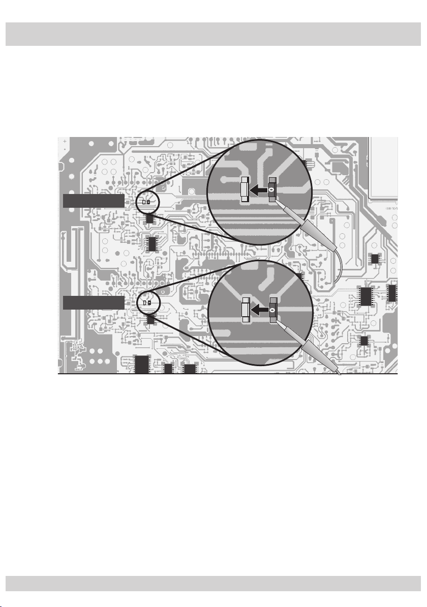
6 Blanking of the video signal
The video signal can be blanked (black screen) for “audio only” transmission.
• Remove the cover on the bottom side of the Cassette.
• On the soldered side of the chassis plate, resolder chip bridges A and B as
shown in the following illustration.
Chip bridge B
Chip bridge A
• Fit the cover on the bottom side of the Cassette.
• Install, fasten and connect the Cassette.
- 21 -
Page 22
- 22 -
7 C band reception
With an appropriate satellite antenna or LNB this Cassette can also receive signals from stations using the C band (4 GHz) for transmission. A negative video
polarity must be set for these stations.
• Remove the cover on the bottom side of the Cassette.
• On the soldered side of the chassis plate, resolder chip bridges C (channel
strip A) and D (channel strip B).
Chip bridge D
Chip bridge C
• Fit the cover on the bottom side of the Cassette.
• Install, fasten and connect the Cassette.
- 22 -
Page 23
- 23 -
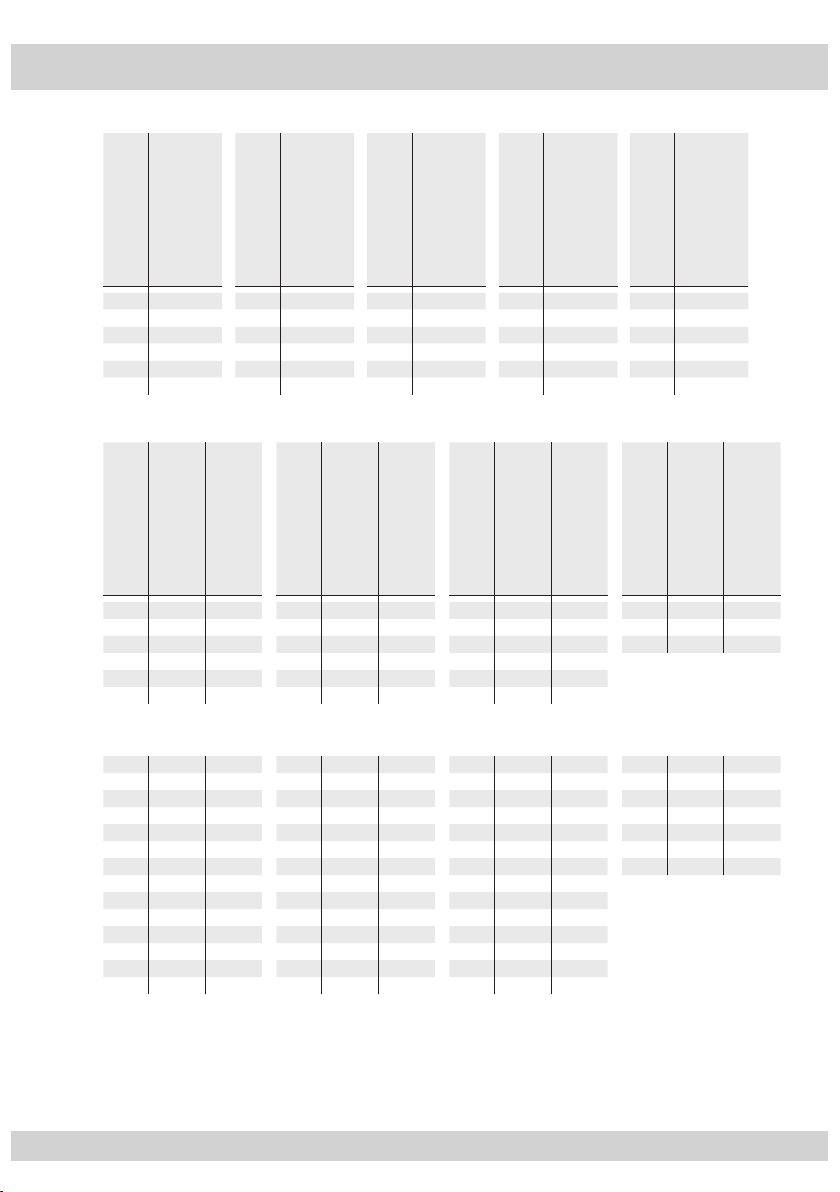
8 Channel and frequency tables
CCIR – Band I/III (Frequency raster 7 MHz)
Kanal
Channel
Bildträgerfrequenz
C 2 48.25
C 3 55.25
C 4 62.25
S 2 112.25
S 3 119.25
S 4 126.25
]
[MHz
Picture carrier frequency
Kanal
Channel
S 5 133.25
S 6 140.25
S 7 147.25
S 8 154.25
S 9 161.25
S 10 168.25
]
Kanal
[MHz
Bildträgerfrequenz
Picture carrier frequency
Channel
C 5 175.25
C 6 182.25
C 7 189.25
C 8 196.25
C 9 203.25
C 10 210.25
]
[MHz
Bildträgerfrequenz
Picture carrier frequency
CCIR – Hyperband (Frequency raster 8 MHz)
]
Kanal
S 21 303.25 306.00
S 22 311.25 314.00
S 23 319.25 322.00
S 24 327.25 330.00
S 25 335.25 338.00
S 26 343.25 346.00
[MHz
Channel
Bildträgerfrequenz
Kanalmittenfrequenz
Picture carrier frequency
Channel centre frequency
]
Kanal
[MHz
S 27 351.25 354.00
S 28 359.25 362.00
S 29 367.25 370.00
S 30 375.25 378.00
S 31 383.25 386.00
S 32 391.25 394.00
]
]
Kanal
[MHz
[MHz
Channel
Bildträgerfrequenz
Kanalmittenfrequenz
Picture carrier frequency
Channel centre frequency
S 33 399.25 402.00
S 34 407.25 410.00
S 35 415.25 418.00
S 36 423.25 426.00
S 37 431.25 434.00
S 38 439.25 442.00
CCIR – Band IV/V (Frequency raster 8 MHz)
C 21 471.25 474.00
C 22 479.25 482.00
C 23 487.25 490.00
C 24 495.25 498.00
C 25 503.25 506.00
C 26 511.25 514.00
C 27 519.25 522.00
C 28 527.25 530.00
C 29 535.25 538.00
C 30 543.25 546.00
C 31 551.25 554.00
C 32 559.25 562.00
C 33 567.25 570.00
C 34 575.25 578.00
C 35 583.25 586.00
C 36 591.25 594.00
C 37 599.25 602.00
C 38 607.25 610.00
C 39 615.25 618.0 0
C 40 623.25 626.00
C 41 631.25 634.00
C 42 639.25 642.00
C 43 647.25 650.00
C 44 655.25 658.00
C 45 663.25 666.00
C 46 671.25 674.00
C 47 679.25 682.00
C 48 687.25 690.00
C 49 695.25 698.00
C 50 703.25 706.00
C 51 711.25 714.00
C 52 719.25 722.00
C 53 727.25 730.00
C 54 735.25 738.00
C 55 74 3.25 746.00
C 56 751.25 754.00
C 57 759.25 762.00
C 58 767.25 770.00
C 59 775.25 778.00
C 60 783.25 786.00
C 61 791.25 794.00
C 62 799.25 802.00
Kanal
Channel
C 11 217.25
C 12 224.25
S 11 231.25
S 12 238.25
S 13 245.25
S 14 252.25
]
[MHz
Channel
Bildträgerfrequenz
Picture carrier frequency
]
Kanal
[MHz
Bildträgerfrequenz
Picture carrier frequency
]
[MHz
Kanalmittenfrequenz
Channel centre frequency
Channel
S 15 259.25
S 16 266.25
S 17 273.25
S 18 280.25
S 19 287.25
S 20 294.25
Kanal
Channel
S 39 447.25 450.00
S 40 455.25 458.00
S 41 463.25 466.00
C 63 807.25 810.00
C 6 4 815.25 818.00
C 65 823.25 826.00
C 66 831.25 834.00
C 67 839.25 842.00
C 68 847.25 850.00
C 69 855.25 858.00
]
[MHz
Bildträgerfrequenz
Picture carrier frequency
]
]
[MHz
[MHz
Bildträgerfrequenz
Kanalmittenfrequenz
Picture carrier frequency
Channel centre frequency
- 23 -
Page 24

Alterations reserved. Technical data E. & O.E. 14052009
 Loading...