

Page 1
A
CLASS
KLASSE
Head-End HDTV Converter to IP
DVB-S2 to SPTS
CCS 1000 S
A
KLASSE
CLASS
Art. No. 325191 GB
Assembly Instructions
TRIAX - your ultimate connection
Page 2

- 2 -
Contents
1 Safety regulations and notes .....................................................................................4
2 General information .................................................................................................5
2.1 Packing contents ..........................................................................................5
2.2 Meaning of the symbols used ........................................................................5
2.3 Technical data .............................................................................................5
2.4 Description .................................................................................................6
2.5 Software query ............................................................................................7
3 Assembly .................................................................................................................8
3.1 Installing the cassette ....................................................................................8
3.2 EMC regulations ..........................................................................................8
3.3 Cassette overview ........................................................................................9
3.4 Connecting the cassette ..............................................................................10
3.5 Retrofitting a CA module ............................................................................10
4 The control panel at a glance ..................................................................................11
4.1 Menu items ...............................................................................................11
4.2 Control panel ............................................................................................11
5 Programming .........................................................................................................12
5.1
Programming procedure
5.1.1 Channel strips “A” (without CA module) and “B” .................................12
5.1.2 Channel strip “A” with CA module ....................................................14
5.2 Programming the cassette ..........................................................................15
Selecting the cassette, displaying the software version ....................................15
Setting the Ethernet parameters ...................................................................16
Setting the IP address of the cassette ............................................................16
Setting the address range ...........................................................................17
Setting the address of the gateway ..............................................................18
Setting the UDP port ...................................................................................18
Selecting the input data stream ....................................................................19
Setting the LNB oscillator frequency .............................................................19
Setting the input symbol rate .......................................................................20
Setting the DVB mode ................................................................................20
Setting the input frequency ..........................................................................21
Testing the signal to noise ratio ....................................................................22
Allocating the IP addresses .........................................................................23
Switching the IP address off or on ................................................................24
Selecting the transmission protocol ...............................................................24
Setting the port number ..............................................................................24
Copying the settings to all IP addresses ........................................................25
Defining the quantity of data packets ...........................................................25
Setting the forward error correction .............................................................25
Setting the transmission channel ..................................................................25
Copying the settings to all IP addresses ........................................................26
Setting IP addresses for services ..................................................................27
..............................................................................12
- 2 -
Page 3

- 3 -
Allocating IP addresses to services manually .................................................27
Allocating IP addresses to services automatically ...........................................27
Allocating services manually .......................................................................28
Selecting the sound options of the service .....................................................29
Switching DVB service information on or off ..................................................30
Copying the settings to all IP addresses ........................................................30
Displaying the output data rate ....................................................................31
Saving settings ..........................................................................................31
5.2.1 Operation with a CA module ............................................................31
Setting the operating voltage for the CA module .................................31
Setting the PID monitoring ................................................................32
Configuring the CA module ..............................................................33
Decoding services ...........................................................................34
6 Final procedures .....................................................................................................35
- 3 -
Page 4

- 4 -
1 Safety regulations and notes
• Assembly, installation and servicing should be carried out by authorised
electricians.
• Switch off the operating voltage of the system before beginning with assembly or service work or pull out the mains plug.
• Do not perform installation and service work during thunderstorms.
• Install the system so it will not be able to vibrate…
- in a dust-free, dry environment
- in such a manner that it is protected from moisture, fumes, splashing
water and dampness
- somewhere protected from direct sunlight
- not within the immediate vicinity of heat sources
- in an ambient temperature of -20 °C to +50 °C.
• Ensure that the head-end station is adequately ventilated. Do not cover
the ventilation slots.
• Beware of short circuits
• No liability is accepted for any damage caused by faulty connections or
inappropriate handling.
• Observe the relevant standards, regulations and guidelines on the instal-
lation and operation of antenna systems.
• Earth the SAT receiver in accordance with DIN EN 50083-1 / 60728-11
and VDE 0855 (earthing, equipotential bonding rail).
• Test the software versions of the head-end station and the cassette and
update them if necessary. The current software versions can be found at
”www.triax.com”.
• For further information please read the assembly instructions for the
head-end station used.
Take action to prevent static discharge when working on the device.
Electronic devices should never be disposed of in the household rubbish. In
accordance with directive 2002/96/EC of the European Parliament and
the European Council from January 27, 2003 which addresses old electronic and electrical devices, such devices must be disposed of at a designated collection facility. At the end of its service life, please take your
device to one of these public collection facilities for proper disposal.
- 4 -
Page 5

- 5 -
2 General information
2.1 Packing contents
1 Cassette CCS 1000 S 2 HF cables
1 CD (assembly instructions) 1 Brief assembly instructions
2.2 Meaning of the symbols used
Important note
—> General note
• Performing works
2.3 Technical data
The devices meet the following EU directives:
2006/95/EC, 2004/108/EC
The product fulfils the guidelines and standards for CE labelling.
HF input
Frequency range: 925 … 2150 MHz
Level range: 60 dBµV … 80 dBµV
Return loss: > 8 dB
Impedance: 75 Ω
DVB-S modes: QPSK 1/2 , 2/3 , 3/4 , 5/6 , 7/8
DVB-S2 modes: QPSK 1/2 , 3/5 , 2/3 , 3/4 , 4/5 , 5/6 , 8/9 , 9/
8PSK
Symbol rate DVB-S: QPSK: 2 … 45 MSymb/s
Symbol rate DVB-S2: QPSK: 10 … 30 MSymb/s
8PSK: 10 … 31 MSymb/s
3
/5 , 2/3 , 3/4 , 5/6 , 8/9 , 9/
10
10
LAN interface
Standard: 100-BASE-T
Data rate: ≤ 80 MBit
Protocols: UDP (User Data Protocol),
RTP (Real-Time Transport Protocol)
ASI interfaces
Standard: DIN EN 50083-9
Format: MPEG ISO IEC 13818-1
User data rate: 2 … 90 Mbit/s
- 5 -
Page 6
- 6 -
Impedance: 75 Ω
Level (input / output): 800 mVPP ± 10%
Return loss (input): > 17 dB (5 … 270 MHz)
Connections
SAT inputs: 2 F sockets
HF output: 1 IEC socket (no function)
LAN: 1 RJ 45 socket
ASI input: 1 BNC socket, 75 Ω
ASI output: 1 BNC socket, 75 Ω
Connection strip (10-pin): for supply voltages and control circuits
RS 232 socket: serial interface for software update
Conditional access: 1 (several channels can be decoded)
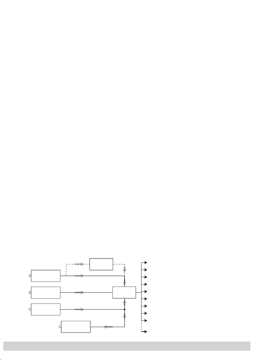
2.4 Description
The cassette is a
DVB-S2 / SPTS
converter which combines modulated services (programmes) in accordance with the DVB-S-/DVB-S2 standard and data
streams supplied via the ASI interface into one data stream in the TPS module.
This is emitted via the LAN interface and can contain up to 16 services. For
operating the cassette in a LAN network it can be assigned its own IP address.
The cassette is equipped with two tuners. The accompanying channel strips
consist of the digital SAT tuners and the digital signal processing levels. The
resulting data streams from the “
Tuner A
”/“
Tuner B
” channel strips and from the
data streams supplied via the ASI socket (ASI – Asynchronous Serial Interface
according to DIN EN 50083-9) can take up to 16 services and are each assigned an IP address.
The signal supplied into the ASI input is provided again
via the ASI output.
Principle signal path:
IP address: Port:
Service 1 212.40.90 : 1234
Service 2 212.40.91 : 1234
Service 3 212.40.92 : 1234
Service 4 212.40.93 : 1234
Service 5 212.40.94 : 1234
Service 6 212.40.95 : 1234
Service 7 212.40.96 : 1234
Service 8 212.40.97 : 1234
Service 9 212.40.98 : 1234
Service 16 212.40.105 : 1234
"Tuner A"
"Tuner B"
ASI input
CA-ModulCA module
TPS
ASI output
- 6 -
Page 7

- 7 -
In the head-end station display, the channel strips of the cassette are indicated
with “
Bx …A
” (“
Tuner A
”) or “
Bx …B
” (“
Tuner B
”). The channel strip “
Tuner A
”
can decode encoded channels via a corresponding CA module. The cassette is
controlled with the head-end station control unit.
Two LEDs provide an indication of the signal quality with their colour. The quality
C/N
of the received transport stream can also be shown in the display (“
” menu).
In an additional menu, the transmission of DVB service information (EIT, TDT and
SDT) or teletext (TXT) can be individually activated or deactivated.
DVB service information:
EIT (Event Information Table):
For each service, event information is transmitted (such as starting time,
duration, encryption etc.)
TDT (Time Date Table):
The transmitted table contains the current time and date.
SDT (Service Description Table):
Information relating to the encryption is also sent with the name of each
service.
The LEDs for the LAN interface show whether a network connection exists and
whether a data transfer is in progress.
When the head-end station is switched on, the two-line LC display shows the
software version of the control unit.
To operate this cassette the software version of the control unit must be “V 41”
or higher. You can find the current operating software for the control unit and
the cassette, the software “BE-Flash” and the current assembly instructions on
the website “www.triax.com”.
The cassette is designed for use in the following head-end stations:
– CSE 3301 – CSE 3308
– CSE 3312 – CSE 3319
2.5 Software query
Control unit
If necessary, you can activate the indication of the software version of the control unit manually:
• Press any two keys on the control unit of the head-end station simultaneously
until the display goes dark and the software version, e.g. “V 41” appears.
Cassette
After activating the cassette the software version of the cassette is displayed (s.
page 15).
- 7 -
Page 8
- 8 -
3 Assembly
A
CLASS
KLASSE
3.1 Installing the cassette
– Ensure the head-end station is mounted so it will not be able to vibrate.
Avoid, for example, mounting the head-end station onto a lift shaft or any
other wall or floor construction that vibrates in a similar way.
– Before installing or changing a cassette unplug the power cable from the
mains power socket.
• Remove the fastening screws
1 of an unoccupied slot from the bracket of the
head-end station.
• Insert the cassette in this slot and push it into the housing.
• Align the cassette and apply slight pressure to connect it to the connections of
the board and the HF bus bar.
• Fasten the cassette with the screws 1.
1
0°
1
3.2 EMC regulations
To comply with the current EMC regulations, it is necessary to connect the
lines leading in and out of the head-end station using cable terminals.
When mounting the cassette in a head-end station which is installed in a
19” cabinet, make sure the connections leading in and out for the 19” cabinet are made using cable terminals.
The attenuation of shielding of the connection lines must meet the require-
A
KLASSE
CLASS
ments for “Class A”.
- 8 -
Page 9
- 9 -
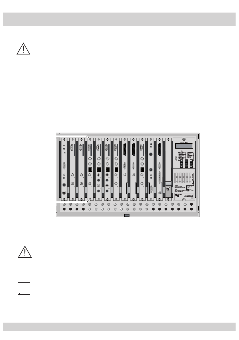
• Insert the required number of cable terminals in the openings provided in the
head-end station or in the 19" cabinet.
—> Cable terminals are not included in the scope of delivery.
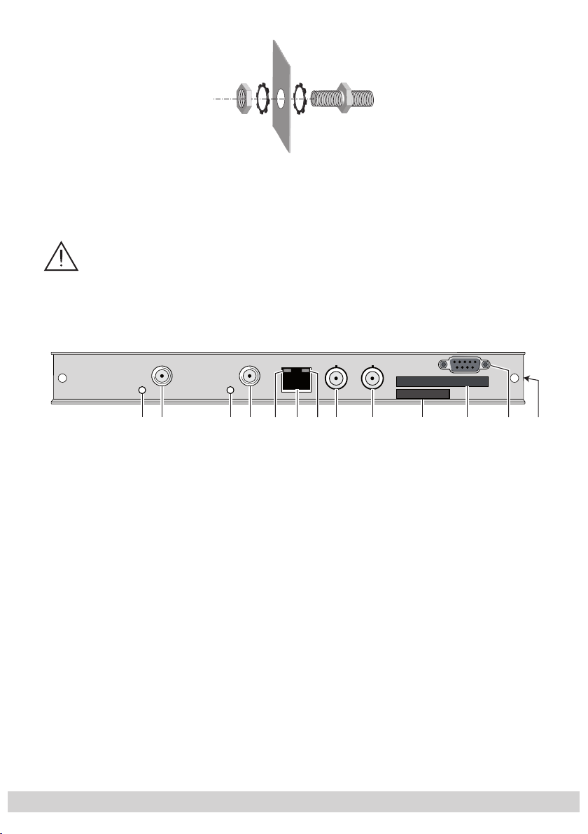
3.3 Cassette overview
Tighten the nuts on the cable terminals until the teeth on the lock washer have
penetrated the exterior coating and a good connection is made between the
housing and cable terminals.
5678 9 ! @2143 0 #
1 Status LED
2 SAT IF input
3 Status LED
4 SAT IF input
of channel strip “
of channel strip “
of channel strip “
of channel strip “
Tuner B
Tuner B
Tuner A
Tuner A
”
”
”
”
5 Status LED of the LAN interface (yellow LED – data transfer)
6
LAN socket
7 Status LED of the LAN interface (green LED – network connection)
8 ASI input
9 ASI output
0 Type label
! Slot for a CA module
@ D-SUB socket “RS 232“
The operating software of the cassette can be updated via the 9-pin D-SUB
socket “RS 232” using a PC or notebook and the software “BE-Flash”.
You can find the current operating software on the website “www.triax.com”.
# MAC address
- 9 -
Page 10
- 10 -
3.4 Connecting the cassette
• Connect the SAT IF connections to the SAT IF input sockets
“
Tuner A
• Connect the LAN socket 6.
• Connect the ASI input 8 and the ASI output 9 to the peripheral ASI devices.
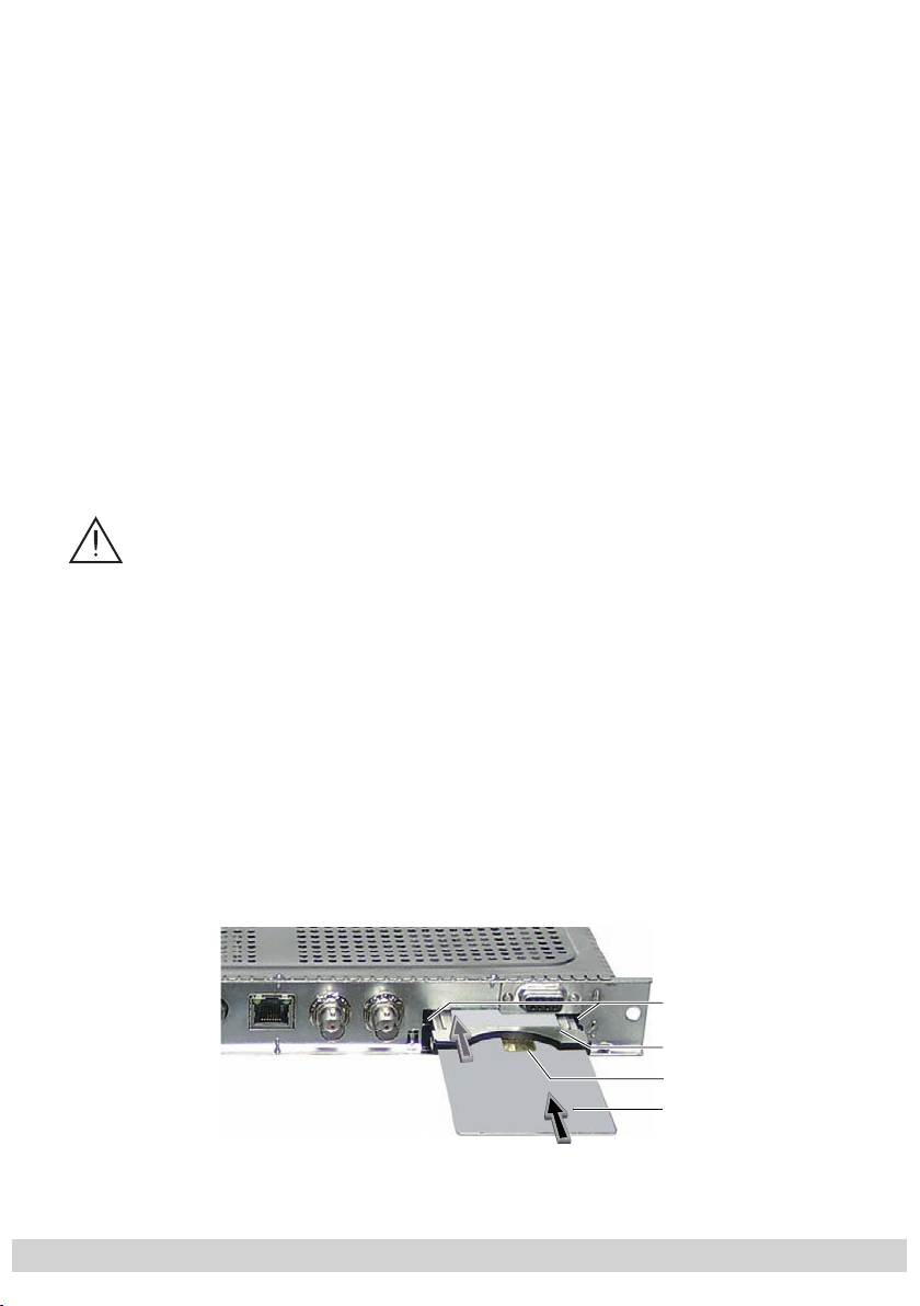
3.5 Retrofitting a CA module
The cassette is equipped with a common interface. It allows you to connect
a CA module for various encryption systems and service providers. Encoded
services (channels) can only be decoded with a CA module suitable for the
encoding system and the corresponding smart card. The smart card contains all
the information for authorisation, decoding and subscription.
– The hardware and software of this cassette have been thoroughly pre-
– When working with the CA module, please read the corresponding op-
”) and 2 (channel strip “
–
Check with the distributor or manufacturer of the CA module to be used
to ensure that it is suitable for decoding several services.
pared and tested.
structures might impair or even prevent this function
erating manual from the respective provider.
Any changes made by service providers in the data
Tuner B
”) (figure in chapter 3.3).
4 (channel strip
.
• Insert the smart card 1 into the CA module 2 so that the chip 3 on the
smart card faces the thicker side (top) of the CA module.
• Insert the CA module into the guide rails of the CA slot 4 with the top side
of the CA module facing the top side of the cassette.
• Push the CA module without canting into the guide rails of the CA slot 4 and
contact it to the common interface.
4
2
3
1
- 10 -
Page 11
- 11 -
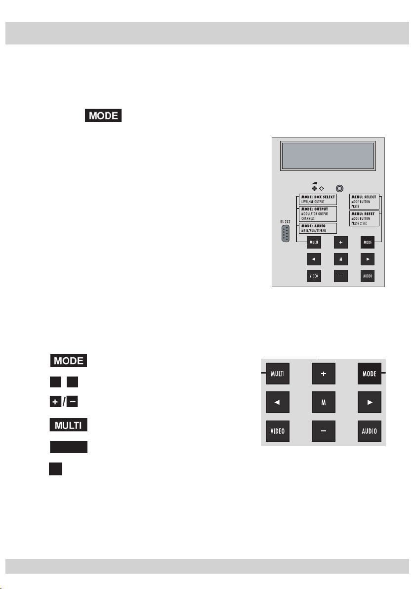
4 The control panel at a glance
4.1 Menu items
Program the
cassette
using the buttons on the control unit of the head-end station.
The two-line display of the control unit then shows the menus.
The parameters and functions to be set are underlined.
Use the key to select the following main menu items:
– Setting Ethernet parameters
– Selecting the input
– Allocating the IP addresses
BE–Remote V 41
please wait . . .
– Displaying the data rate
4.2 Control panel
The key pad on the head-end station is used to scroll through the menus and
menu items one at a time:
scrolls forward through the menus.
◀
▶
/
select parameters in the menus.
set values, initiate actions.
selects sub-menus.
AUDIO
M
scrolls backward through the menus.
saves all entries.
- 11 -
Page 12

- 12 -
5 Programming
BE–Remote
please wait …
V 41
Box 4
V 11
DVBS2-SPTS
– – –
1
…………………
……
+
t > 10 s
Bx 4
stat =>
ETHERNET
Options
stat / DHCP
A
Bx 4
192.168. 0. 1
IP-GATEWAY
Bx 4
255.255.255. 0
IP-MASK
Å
Ï
/
Bx 4
192.168. 0.128
IP-ADDR
Å
Ï
/
Å
Ï
/
Bx 4
60000
UDP-PORT
Å
Ï
/
B
Å
0 … 65535
Ein / On
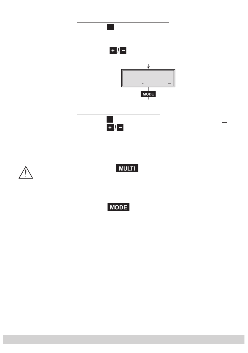
5.1
Programming procedure
5.1.1 Channel strips “A” (without CA module) and “B”
Box
Box 5
page 14
- 12 -
Page 13

- 13 -
Tuner A /
Tuner B /
ASI
Bx 4A
11836 -1.8
FREQ
CN 12
Bx 4A
27500 DVB-S
SYMBOL
Å
Ï
/
Å
Ï
/
Bx 4A
10600 MHz
LNB
Å
Ï
/
Å
Bx 4
Tuner A OK
INPUT
=>
C
D
Kanalzug “A” mit CA-Modul
Channel strip “A“ with
CA module
Kanalzug “A”
ohne CA-Modul,
Kanalzug “B” /
Channel strip “A“
without CA module,
Channel strip “B“
DVB-S / QPSK… /
8PSK… / DTV…
Å
Ï
/
Bx 4A
12.0 dB
C/N
(+ 9.6) OK
Anzeige:
Signalqualität
Display:
Signal quality
10600 / 9750
27500 / 22000
IP-OUT 1
…
IP-OUT 16
IP 1
227. 40. 50. 60
OUT-IP
IP 1
7 off
PKTS / FEC
Å
Ï
/
IP 1
on UDP
MODE / PORT
1234
Å
Ï
/
Å
Bx 4
Das Erste
IP-OUT 1
=>
on / off
UDP / RTP,
0 … 65535
copy
off / 10/9 … 20/19
Annex A / Annex B
001/016
IP 1 TV
Das Erste
all / 01/…
IP 1
all
AUDIO
copy1 … 7
Å
Ï
/
auto
page 14
page 14
- 13 -
Page 14

- 14 -
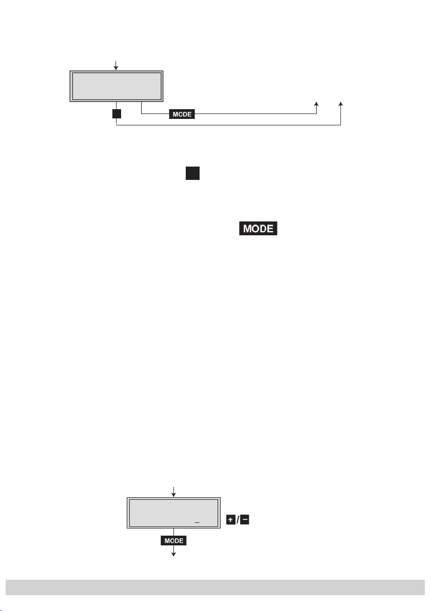
5.1.2 Channel strip “A” with CA module
A
M
B
Bx 4
72.956 Mbps
DATARATE
Bx 4
EIT TDT TXT SDT
OPTIONS
Å
Ï
/
EIT / eit, TDT / tdt,
TXT / txt, SDT / sdt
(ON / off)
copy
Bx 4A
Menu <=
CA
=> Edit
*) Die angezeigte Information ist
abhängig vom verwendeten
CA-Modul.
The information displayed is
dependent on the CA module
used.
Bx 4A 01/03
Information *)
MENU
Bx 4A TV X
. . . .
04/09
S
X – entschlüsselt
decrypted
0 – verschlüsselt
encrypted
X / 0
nächster Service
next service
Bx 4A
PID Check
CA
on
Å
Ï
on / off
M
Å
Ï
/
D
Bx 4A
Menu <=
CA
=> Edit
Bx 4A
Supply
CA
5.0 V
3.3 V / 5.0 V
C
page 13
page 12
page 13
- 14 -
Page 15

- 15 -
5.2 Programming the cassette
BE–Remote
please wait …
V 41
t > 10 s
Ein / On
Box 4
V 11
DVBS2-SPTS
– – –
1
+
A
—> Pressing the
button for longer than 2 seconds cancels the programming procedure. This takes you back to the program item “Selecting
the cassette” from any menu. Any entries that have not been saved are
reset to the previous settings.
M
—> Entries in the menus can be saved by pressing the
key. You are taken
back to the “Selecting the cassette” menu item.
—>
Using the
AUDIO
button previous menus can be activated.
• Switch on the head-end station
—> The display shows the software version (e.g. V 41)
—> The processor reads the
cassettes
‘ data
(approx. 10 seconds).
Selecting the cassette, displaying the software version
Box
Box 5
• Select the
cassette
you want to program (e.g. Box 4) by
repeatedly pressing the button if necessary.
—> The display shows e.g. the menu
“Box 4” stands for
”
”V 11” software version of the cassette
DVBS2-SPTS
- 15 -
” type of cassette
“Box 4 DVBS2-SPTS“
slot
4
:
Page 16

- 16 -
• Press the button.
Bx 4
stat =>
ETHERNET
Options
stat / DHCP
Bx 4
192.168. 0.128
IP-ADDR
Å
Ï
/
B
Å
4
/
—> The “Setting the Ethernet parameters” – “ETHERNET”
menu is activated.
Setting the Ethernet parameters
In this menu you specify whether the Ethernet parameters
for the cassette are entered automatically by a connected
server (“DHCP”), or whether you want to enter them manually
(“stat”). To assign the cassette uniquely, each IPTV cassette
must be allocated its own IP address.
• Press the
Bx
192.16. 0.12
buttons to select manual setting (”stat”) or
IP-ADDR
automatic setting (”DHCP”) of the Ethernet parameters.
• Press the
—> The “Setting the IP address of the cassette”
▶ button to activate the setting options
(”Options”)
– menu
.
“IP-ADDR” is activated.
Setting the IP address of the cassette
If you choose to enter the Ethernet parameters manually,
set the IP address of the cassette in this menu. If “DHCP”
is selected, the “IP-ADDR”, “IP-MASK” and “IP-GATEWAY”
sub-menus display the parameters that were assigned automatically by a connected server. If a server is not connected,
“ 0. 0. 0. 0*” appears in the corresponding menu.
The star “ * ” in the display means that the data is provided
by a DHCP server.
- 16 -
Page 17

- 17 -
Bx 4
stat =>
ETHERNET
Options
stat / DHCP
Bx 4
192.168. 0.128
IP-ADDR
Å
Ï
/
B
Å
stat / DHC
P
B
Bx 4
255.255.255. 0
IP-MASK
Å
Ï
/
tat =>
Options
◀
• Use the
▶
buttons to place the cursor under the digit
/
of the IP address displayed to be set and use to set
the IP address wished.
• Press the
—> The “Setting the address range”
button.
– “IP-MASK” menu is
activated.
Setting the address range
In this menu you define the address range for the cassettes
connected to the LAN network.
◀
• Use the
▶
buttons to place the cursor under the digit
/
of the IP address displayed to be set and use to set
the IP address wished.
• Press the
—> The “Setting the address of the gateway”
button.
–
“IP-GATEWAY” menu is activated.
- 17 -
Page 18

- 18 -
Setting the address of the gateway
Bx 4
192.168. 0. 1
IP-GATEWAY
Å
Ï
/
Bx 4
60000
UDP-PORT
Å
Ï
/
0 … 65535
The address of a gateway (server) can be set in this menu. If
no gateway is used you can skip this setting.
◀
• Use the
▶
buttons to place the cursor under the digit
/
of the IP address displayed to be set and use to set
the IP address wished.
• Press the
—> The “Setting the UDP port”
button.
– “UDP-PORT” menu is
activated.
Setting the UDP port
The UDP port setting is required if the cassette needs to be
reached externally to make the setting, such as from another
input frequency. This setting is intended for future functions
and can be skipped for this cassette.
◀
• Use the
▶
buttons to place the cursor under the digit
/
of the port number displayed to be set and use to
set the port number wished (”0” … ”65535”).
• Press the
—> The “Selecting the input data stream”
button.
– “
INPUT
” menu
is activated.
- 18 -
Page 19

- 19 -
Selecting the input data stream
Tuner A /
Tuner B /
ASI
Bx 4A
10600 MHz
LNB
Å
Ï
/
Å
Bx 4
Tuner A OK
INPUT
=>
D
10600 / 9750
A
z
/
Tuner A /
Tuner B /
ASI
Bx 4A
10600 MHz
LNB
Å
Ï
/
Å
Bx 4
Tuner A OK
INPUT
=>
D
10600 / 9750
/
/
A
4
T
D
In this menu you select the signal source for the selection of
the services. The data streams to be processed are provided
by ”Tuner A”, ”Tuner B” and the ASI interface ”ASI”.
uner A
uner B
SI
Bx
u
r A OK
• Press the
Bx 4
106 MH
buttons to select the signal source of the
NB
10600 / 9750
input data stream (”Tuner A”, ” Tuner B”, ”ASI”).
—> ”OK” indicates that an input signal is available. If
there is no input signal available ”– –” is displayed
instead of ”OK”.
• Press the ▶ button.
—> The “Setting the LNB oscillator frequency” – “
menu is activated.
Setting the LNB oscillator frequency
Set the oscillator frequency of the LNB used in this menu.
INPU
=
LNB
”
• Using the button the oscillator frequencies ”10600“
or ”9750“ can be selected directly.
◀
• To set other oscillator frequencies use the
▶
buttons to
/
place the cursor under the digit of the oscillator frequency
displayed to be set.
• Press to enter the respective digit of the oscillator
frequency of the LNB used.
• Repeat the procedure by the quantity of the digits to be
set.
- 19 -
Page 20

- 20 -
• Press the button.
Bx 4A
27500 DVB-S
SYMBOL
Å
Ï
/
Å
Ï
/
D
DVB-S / QPSK… /
8PSK… / DTV…
27500 / 22000
—> The “Setting the input symbol rate, setting the DVB
mode” – “SYMBOL” menu is activated.
Setting the input symbol rate
Setting the DVB mode
The symbol rates of the satellite transponders can be found in
the current channel table of the satellite operator, in various
satellite magazines and in the Internet.
The cassette recognizes the transmitted DVB mode and
switches over between the normal QPSK mode (DVB-S) and
the DVB-S2 mode. Receiving stations with DVB-S2 mode,
we suggest to preset the DVB mode to shorten the time for
searching stations.
Setting the input symbol rate
• Using the
button the symbol rates 27500“ or
”22000“ can be selected directly.
◀
• To set other symbol rates use the
▶
buttons to position
/
the cursor under the digit of the symbol rate displayed to
be set.
• Press
to enter the respective digit of the symbol rate
needed.
• Repeat the procedure by the quantity of the digits to be set.
Setting the DVB mode
• Use the
set the required DVB-S2-mode with the
▶
button to place the cursor under “DVB-S” and
buttons.
• Press the button.
—> The “Setting the input frequency” – “FREQ” menu is
activated.
- 20 -
Page 21

- 21 -
Setting the input frequency
Bx 4A
11836 -1.8
FREQ
CN 12
C
Kanalzug “A” mit CA-Modul
Channel strip “A“ with
CA module
Kanalzug “A”
ohne CA-Modul,
Kanalzug “B” /
Channel strip “A“
without CA module,
Channel strip “B“
Å
Ï
/
Bx 4A
12.0 dB
C/N
(+ 9.6) OK
Anzeige:
Signalqualität
Display:
Signal quality
If three dots “ … “ appear in the second line of the display,
the cassette is in the “station search” mode. Please wait until
the process has finished.
Once the HF receiver has synchronised to the input signal,
any offset to the target frequency is displayed in MHz, e.g.
“– 1.8”.
If a question mark “?” appears in the second line of the display, there is no input signal present. Check the configuration
of the antenna system and head-end station as well as the
preceding settings of the cassette.
◀
• Use the
▶
buttons to position the cursor under the
/
digit of the frequency displayed to be set.
• Press
• Set the frequency offset shown in the display
to less than 1 MHz
the
to set the input frequency.
by varying the input frequency
buttons.
(e.g. “– 1.8”)
using
—> The ”CN 12” display indicates the signal to noise ra-
tio of the signal received.
• Press the button.
—> The “Testing the signal to noise ratio” – “C/N” menu
is activated.
- 21 -
Page 22

- 22 -
Testing the signal to noise ratio
In this menu you can estimate the quality of the input signal.
C/N
(+ 9.6) OK
Bx 4A
12.0 dB
1 Current signal to noise ratio
2 This value shows the difference between the quality
of the input signal and the threshold of the tuner at
this type of modulation.
At a value lower than “5” picture dropouts can occur.
3 If “OK” is shown, the signal to noise ratio is ok.
If a value < 5 is shown under 2 the display changes
from “OK” to “??”. In this case test the input signal.
—> In addition to the indicator in the display, there is a
status LED which indicates the quality of the received
transport stream (level and C/N).
—> If the LED lights yellow the SAT IF input level and the
signal to noise ratio must be tested.
Status LED
"Tuner A"
LED indicator Indication
Green Signal quality is good
Yellow
Red No signal
Signal quality is insufficient
Status LED
"Tuner B"
• Press the button
- 22 -
to return to the main menu.
Page 23

- 23 -
• Press the button.
IP-OUT 1
…
IP-OUT 16
IP 1
on UDP
MODE / PORT
1234
Å
Ï
/
Å
Bx 4
Das Erste
IP-OUT 1
=>
on / off
UDP / RTP,
0 … 65535
copy
1
T
4
/
—
> The “Selecting the input data stream”
– “INPUT” menu
is activated when the input signal source “Tuner A”
without a
CA module installed
and “Tuner B” are pro-
grammed (page 19).
—> Programming the input signal source “Tuner A” with
a CA module installed the “Setting the operating voltage for the CA module” – “CA Supply” menu is
activated (page 31).
• Use the
(“Tuner
buttons to select further input signal sources
B” / “
ASI
”) and program them.
• Press the button.
—> The “Allocating the IP addresses” – “IP-OUT 1” menu
is activated.
Allocating the IP addresses
In this menu up to 16 services that are contained in the data
streams of the input source signals (“Tuner A”, “Tuner B”,
“ASI”) can be accessed. The services detected receive an IP
address automatically.
In the following sub-menus you can set specific parameters
for each service.
• Press the
(“IP-OUT 1
IP
buttons to select the IP outputs to be set
” … “
IP-OUT 16
ODE / POR
123
”).
on / off
DP / RTP,
… 65535
—> In the second line of the display the service is indi-
cated allocated to the IP output (e.g. ”Das Erste”).
• Press the ▶ button.
—> The “Switching the IP address off or on, selecting the
transmission protocol, setting the port number” –
“
MODE / PORT
- 23 -
” menu is activated.
Page 24

- 24 -
Switching the IP address off or on
IP-OUT 1
…
IP-OUT 16
IP 1
on UDP
MODE / PORT
1234
Å
Ï
/
Å
Bx 4
Das Erste
IP-OUT 1
=>
on / off
UDP / RTP,
0 … 65535
copy
1
6
4
e
Bx 4
off
IP-OUT 1
=>
Å
Selecting the transmission protocol
Setting the port number
In this menu you can switch off the IP address displayed, and
define the transmission protocol and the port number.
IP-OUT
IP-OUT 1
Bx
as Erst
IP-OUT
=
Switching the IP address off or on
• Press the
buttons to switch off (”
off”) or (“on
”) the IP
address and the service referred.
—> In the second line of the ”IP-OUT …” menu ”off” is
displayed instead of the service referred.
Selecting the transmission protocol
• Press the ▶ button to position the cursor under ”UDP” or
“RTP”.
• Using the buttons to select the transmission protocol
wished:
“UDP” – The User Datagram Protocol is for the connec-
tionless transmission of data to a certain application. The port number of the service is also sent
which the data should obtain.
“RTP” – The Real-time Transport Protocol is for continu-
ously transmitting multimedia data streams in an
IP network. Unlike UDP, the header is transmitted
which makes the data transmission more robust.
- 24 -
Page 25

- 25 -
Setting the port number
IP 1
7 off
PKTS / FEC
Å
Ï
/
off / 10/9 … 20/19
Annex A / Annex B
copy1 … 7
• Press the ▶ button to position the cursor under the port
number e.g. ” 1234”.
◀
• Use the
▶
buttons to position the cursor under the
/
digit of the port number displayed to be set.
• Using the
buttons set the port number wished.
Copying the settings to all IP addresses
• Pressing the
button the settings ”transmission protocol” and ”Port number” can be copied to all IP addresses.
—> The display shows ”
copy
” for a short time.
• Press the button.
—> The “Defining the quantity of data packets, setting
the forward error correction, setting the transmission
channel” – “PKTS / FEC” menu is activated.
Defining the quantity of data packets
Setting the forward error correction
Setting the transmission channel
In this menu you set the quantity of the data packets to be
transmitted, the forward error correction FEC and the transmission channel. If the forward error correction is used the
data to be transmitted is encoded in a redundant way so that
the addressee can correct transmission errors.
Defining the quantity of data packets
• Using the buttons define the quantity of MPEG data
packets in one IP data packet (”1” … ”7”).
- 25 -
Page 26
- 26 -
Setting the forward error correction
IP 1
7 10/09
PKTS / FEC
AnnexB
• Press the ▶ button to position the cursor under ”off” .
—> In position ”off” the forward error correction (FEC) is
switched off.
• Using the buttons set the value of the FEC wished
(”off, 10/9” … ”20/19”).
Setting the transmission channel
▶
• Press the
button to position the cursor under ”Annex…”.
• Use the buttons to set the transmission channel
wished (”AnnexA” / ”AnnexB”).
Copying the settings to all IP addresses
• Pressing the
button the settings ”Quantity of the
data packets”, Forward error correction” and ”Transmission channel” can be copied to all IP addresses.
—> The display shows ”
copy
” for a short time.
• Press the button.
—> The “Setting IP addresses for services” – “OUT-IP”
menu is activated.
- 26 -
Page 27

- 27 -
Setting IP addresses for services
IP 1
227. 40. 50. 60
OUT-IP
Å
Ï
/
auto
In this menu you set the IP address for the IP output selected.
The software allows to allocate IP addresses to 16 services
automatically in ascending order after setting the IP address.
If an already available IP address is occupied, an exclamation mark ” ! ” appears in the first line of the display beside
the number of the IP output.
IP 1 !
227. 40. 50. 60
OUT-IP
Allocating IP addresses to services manually
◀
• Press the
▶
buttons to position the cursor under the
/
digit of the IP address to be set.
• Using the buttons set the IP address wished
.
Allocating IP addresses to services automatically
• Pressing the
button the first 16 of the present services are occupied with IP addresses in ascending order,
starting from the IP address set.
—> The display shows ”
auto
” for a short time.
• Press the button.
—> The “Allocating services manually” menu is activat-
ed.
- 27 -
Page 28

- 28 -
Allocating services manually
001/016
IP 1 TV
Das Erste
In this menu all services (programmes) supplied via “Tuner A”, “Tuner B” and “ASI” can be displayed and each serv-
ice is assigned a set IP address in the “OUT-IP” menu. The
service can be accessed in the connected network using the
given IP addresses for this output in the “OUT-IP” menu.
• Using the buttons select the service wished
—> The display shows e.g.:
Das Erste
IP 1 TV 001/016
.
Meaning of the indicators in the example:
“IP 1” – IP address with the consecutive number ”1”
“TV” – ”Television” (type of service)
“0
01/016” – The 1st of 16 services is being allocated
to the IP address.
“
Das Erste
” – Name of the service
Further possible terms displayed:
“RA” ”Radio” (type of the service)
For radio stations, the
screen of the connected TV
or test receiver is darkened.
“ * ” The star means that the TV or radio station se-
lected is encoded. To enable the stations, the CA
module and the appropriate smart card of the
station provider are required.
—> If a service number (e.g. “131”) appears instead of
“TV” or “RA”, this indicates that an unnamed station
or an undefined data stream is being received.
- 28 -
Page 29

- 29 -
If the service selected is already allocated to an IP address,
all / 01/…
IP 1
all
AUDIO
in the first line of the display an exclamation mark ” ! ” appears beside the type of the service.
IP 1 TV !
Das Erste
001/016
If no service is found the display shows “– – –” instead of the
name of the service. In this case check the configuration of
the antenna system including the head-end station and the
previous settings of the cassette as well as the components
connected to the ASI input.
• Press the
button.
—> The “Selecting the sound options of the service” –
“AUDIO” menu is activated.
Selecting the sound options of the service
If several sound options in different languages, Dual sound
(“2ch”) or AC3 are transmitted in a service, you can select
the desired audio stream from the transport stream in this
menu.
• Press
to select the desired sound option (e.g. ”all”,
”deu” – German, ”2ch” etc.).
• Press the button.
—> The “Switching DVB service information on or off” –
“OPTIONS” menu is activated.
- 29 -
Page 30

- 30 -
Switching DVB service information on or off
Bx 4
EIT TDT TXT SDT
OPTIONS
Å
Ï
/
EIT / eit, TDT / tdt,
TXT / txt, SDT / sdt
(ON / off)
copy
In this menu the transmission of the DVB service information
(EIT – Event Information Table, TDT – Time Date Table, TXT –
Teletext, SDT – Service Description Table) can be activated
or deactivated.
◀
• Use the
▶
buttons to position the cursor under the
/
transmission option to be activated or deactivated.
• Using the buttons activate
”
SDT”) or deactivate
(”
eit
”, ”
tdt
”, ”
(”
EIT
”, ”
txt
”, ”
sdt”) the transmis-
TDT
”, ”
TXT
”,
sion option wished.
—> Activated options are shown with capital letters, de-
activated with small letters.
Copying the settings to all IP addresses
• Pressing the
button the settings can be copied to
all IP addresses.
—> The display shows ”
copy
” for a short time.
• Press the button.
—> The “Allocating the IP addresses” – “IP-OUT …” menu
is activated (page 23).
• Repeat the settings until all services wished are allocated
to an IP address.
• Press the button.
—> The “Displaying the output data rate” – “DATARATE”
menu is activated.
- 30 -
Page 31
- 31 -
Displaying the output data rate
A
M
B
Bx 4
72.956 Mbps
DATARATE
In this menu the current data rate is displayed.
Saving settings
• Press the
—> The settings are saved.
—> You will be returned to the menu item “Selecting the
cassette” via connection A (page 15).
—> By pressing the button, you will be returned
to the menu item “Setting the Ethernet parameters” via
B
5.2.1 Operation with a CA module
In order for this function of the CA module to be possible, in
the “Selecting the input data stream” – “INPUT” menu (page
19) an input signal source must be selected whose data
stream contains services which can be decoded by the CA
module you are using and your smart card. Where both encrypted and unencrypted services are transmitted, short-term
picture loss may occur when switching between encrypted
and unencrypted services.
M
button.
without
saving the programmed data
(page 16).
Setting the operating voltage for the CA module
In this menu the operating voltage for the CA module can
be set.
Bx 4A
Supply
C
CA
5.0 V
- 31 -
3.3 V / 5.0 V
Page 32

- 32 -
• Use the buttons to set the operating voltage for the
CA module (”3.3 V“ / ”5.0 V“).
• Press the button.
—>
The “Setting the PID monitoring” – “CA”
menu
is acti-
vated.
Setting the PID monitoring
The factory default of the PID monitoring is switched on.
If particular PIDs are not decrypted the CI module is reset.
Additionally dropouts may occur if several services are decrypted. To prevent this the PID monitoring can be switched
off.
Bx 4A
PID Check
CA
on
on / off
• Use the
buttons to switch “off” or “on” the PID moni-
toring.
• Press the button.
—>
The “Configuring the CA module” – “CA” menu is activated.
- 32 -
Page 33

- 33 -
Configuring the CA module
Bx 4A
Menu <=
CA
=> Edit
*) Die angezeigte Information ist
abhängig vom verwendeten
CA-Modul.
The information displayed is
dependent on the CA module
used.
Bx 4A 01/03
Information *)
MENU
Bx 4A TV X
. . . .
04/09
S
X – entschlüsselt
decrypted
0 – verschlüsselt
encrypted
X / 0
nächster Service
next service
Å
Ï
M
Å
Ï
/
X
üsse
d
üsse
d
X /
e
ce
/
The menu varies according to which CA module you are
using. For this reason, please refer to the operating manual
of your particular CA module. The relevant information is
shown in the display of the head-end station. This may appear as a fixed display or as scrolling text according to display capabilities.
0
/09
–
ntschl
ecrypte
0 – verschl
ncrypte
ächster Servic
next servi
lt
lt
—> By pressing the
button you can skip the
“Configuring the CA module” – “CA” menu and activate the “Selecting the input data stream” – “INPUT”
menu (page 19).
• Press the ◀
button to activate the menu of the CA module.
—> The display shows e.g.: Bx 4A 01/03 MENU
Information
Meaning of the indicators:
“Bx 4A” – Slot 4, channel strip “Tuner A”
“
01/03
” – The first of three menu items is activated.
“
MENU
For the explanation of further details please use the operating instructions of the CA module used.
” – The menu of the CA module is activated.
- 33 -
Page 34

- 34 -
• Use the buttons to activate the menu desired.
Bx 4A
Menu <=
CA
=> Edit
*) Die angezeigte Information ist
abhängig vom verwendeten
CA-Modul.
The information displayed is
Bx 4A 01/03
Information *)
MENU
Bx 4A TV X
. . . .
04/09
S
X – entschlüsselt
decrypted
0 – verschlüsselt
encrypted
X / 0
nächster Service
next service
Å
Ï
M
Å
Ï
/
3
)
• Press the ▶ button to activate the menu.
• Use the buttons to select the function desired.
◀
• To set the CA module use the
▶
and buttons.
/
• All settings are saved by pressing the M button.
—> You will be returned to the “Configuring the
CA module” – “CA” menu item.
By pressing the button you can cancel the
—>
settings in the menu of the CA module and are returned
to the “Configuring the CA module” – “CA” menu.
• Press the ▶ button.
—> The “Decoding services” – “Edit” menu is activated.
Decoding services
In this menu you select the services wished from the encoded
data stream, which are to be decoded.
—> The display shows e.g.:
. . . .
Bx 4A TV X 04/09
Bx
A 0
/0
ENU
Information *
Meaning of the indicators in the example:
“Bx 4A” – Slot 4, channel strip “Tuner A”
“TV” – ”Television” (type of service)
“X” –
decrypted.
“
04/09” – The 4th of 9 services is displayed.
“
. . . .
” – Name of the service
The currently
- 34 -
selected
service is
Page 35

- 35 -
Further possible terms displayed:
D
Bx 4A
Menu <=
CA
=> Edit
“RA” – ”Radio” (type of service)
“0”
–
• Use the
◀
order which are to be decoded, then use
The currently selected service is
encrypted.
▶
buttons to call up the services in sequential
/
to decrypt
(“X”) or not to decrypt them (“0”).
•
Save changes and activate the filter:
Press the button.
—> The filter is activated. The display shows the
“Configuring the CA module” – “CA” menu.
• Press the button.
—> The “Selecting the input data stream” – “INPUT”
menu is activated (page 19).
6 Final procedures
After installing the head-end station, upgrading accessories or installing
cassettes it is necessary to tighten all cable connections, cable terminals
and cover screws in order to maintain compliance with current EMC regulations securely.
• Securely tighten the cable bolted connections fingertight using an appropriate
open-ended spanner.
• Mount the front cover (s. assembly instructions of the head-end station).
- 35 -
Page 36

Alterations reserved. Technical data E. & O.E. 26102009
 Loading...