

Page 1
| GB |891072E
TDX Headend Unit - Art. No. 492090
User guide
Page 2

2
Contents
Contents
Introduction............................................................................................................................ 4
Box content ............................................................................................................................ 5
Unit - exterior ......................................................................................................................... 5
Unit - interior .......................................................................................................................... 6
Mounting ................................................................................................................................ 8
Earthing ................................................................................................................................. 9
Input modules ....................................................................................................................... 9
Output modules .................................................................................................................. 12
CAM/Smart card ................................................................................................................ 14
Small Form-factor Plugable (SFP) ..................................................................................... 14
Connecting units ................................................................................................................. 15
ID switch ............................................................................................................................ 18
Power and RF output .......................................................................................................... 19
LEDs ..................................................................................................................................... 20
Configuration of system ..................................................................................................... 22
Log in .................................................................................................................................... 23
System window ................................................................................................................... 24
System information ............................................................................................................ 25
Communication icon .......................................................................................................... 26
Administration window ....................................................................................................... 26
Language settings ............................................................................................................. 27
Country settings ................................................................................................................. 28
Time zone settings ............................................................................................................. 29
Password settings ............................................................................................................. 31
Licence handling ................................................................................................................ 32
IP settings .......................................................................................................................... 33
Save settings ..................................................................................................................... 36
Create a new system configuration ................................................................................... 37
Save configuration .............................................................................................................. 38
Change system configuration ............................................................................................ 38
IPTV window ........................................................................................................................ 39
IPTV configuration window ................................................................................................ 40
Status information ............................................................................................................. 43
Delete IP group ................................................................................................................. 44
Log file .................................................................................................................................. 45
Update firmware .................................................................................................................. 48
Reboot system ..................................................................................................................... 53
Load to TDX ......................................................................................................................... 54
Load from TDX ..................................................................................................................... 55
Configuration of modules ................................................................................................... 56
Technical data ...................................................................................................................... 57
Your notes ....................................................................................................................... 58-59
Manufacturer ....................................................................................................................... 60
Declaration of conformity ................................................................................................... 60
Page 3
3
Safety Precautions
Environment
Operating temperature from -10 C to +50 C.
Storage temperature from -20 C to + 70 C.
Max. operating humidity 80% (RH).
Max. storage humidity 90% (RH).
Power supply
The input voltage must be 190-264 VAC. ~ 45/65 Hz / 280 W (Max).
Use only power connections installed by professionals.
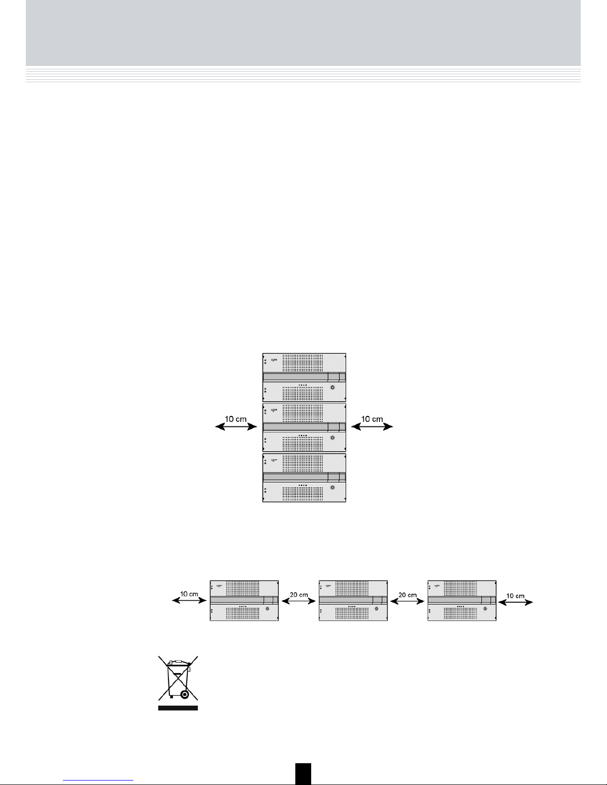
Ventilation
The way you position the headend units must leave a minimum of
10 cm on each side of the units for ventilation.
If you position the headend units side by side, the distance between the
units must be at least 20 cm.
Disposal
Within in the European Union this label indicates that the product
cannot be disposed of with the general household waste.
Neither the headend nor the input and output modules can be disposed of with the general household waste.
For proper treatment and recycling of old products, please take
them to designated collection points in accordance with your national legislation.
Earth
Every unit in your headend system must be earthed by connecting it
to the ground with a wire according to the electrical regulations of your
country.
Safety precautions
Page 4

4
Introduction
With the TDX headend system, Triax introduces the TDX IP-pool which
provides you with the full freedom of assigning services from any input
to any set of output modules.
All incoming signals from input modules initially arrive in the TDX IP-pool.
From this pool they can be converted into any output signals you require
while simultaneously being fed to several different output modules.
Besides, the configuration of input and output modules can be readily
changed at any time.
The ability of converting any input signal to any output signal makes the T
DX headend system uniquely flexible, efficient and economical.
Introduction
Page 5
5
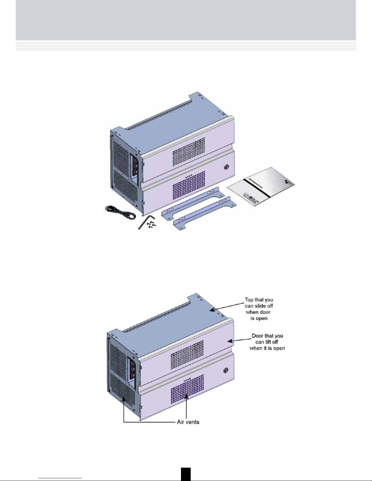
Unpacking
Included in the box you will find the TDX headend unit, key, brackets, Torx®
key, screws, a power lead and a user guide.
Box content
Unit - exterior
In order to make it easy for you to work with a TDX headend unit you can remove the door and the top from the unit.
Everything you need to do in connection with the headend unit you can do
from the front of the unit.
Note
Before you leave a headend system, the extractor fan in the output
section must be clicked into place in the middle of this section and
the door must be closed due to heat and EMC.
Page 6
6
TDX Unit
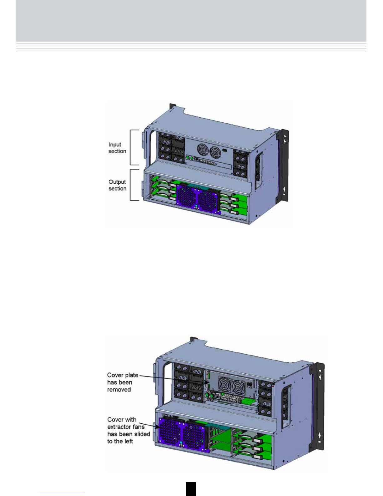
Unit - interior
Inside the TDX unit the interior is divided into two parts, an upper part - input
section - containing all the input modules, and a lower part - output section containing all the output modules.
In the input section covers are used to protect all module slots.
For EMC reasons only remove covers from the module slots that you want to
insert modules into.
Extractor fans have been placed in both the input section and the output
section of the unit to prevent the unit from overheating.
In the output section you can slide the cover with the extractor fans from one
side of the output section to the other when you want to install or replace
output modules.
Page 7
7
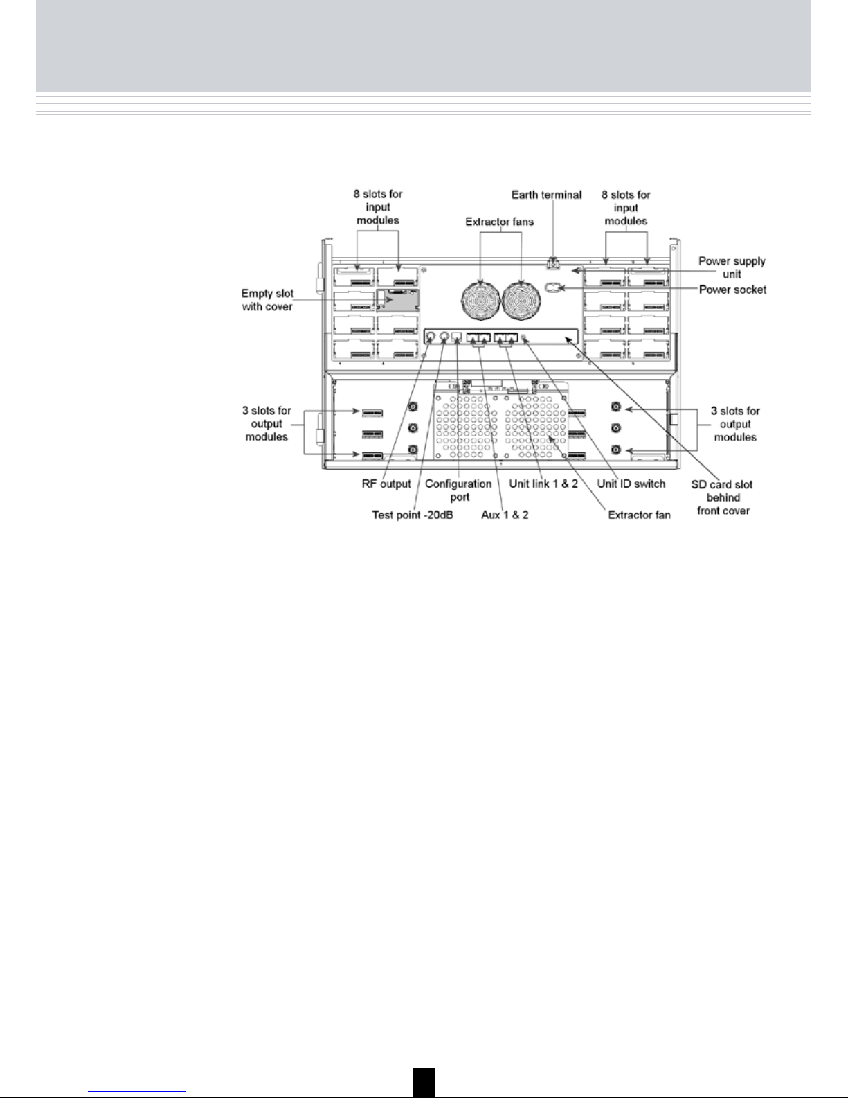
Below you can see an empty headend unit without the front and top.
TDX Unit
RF output
Distributes the RF channels from the output modules
using an F-connector.
Test point -20 dB
RF test point of output (-20 dB).
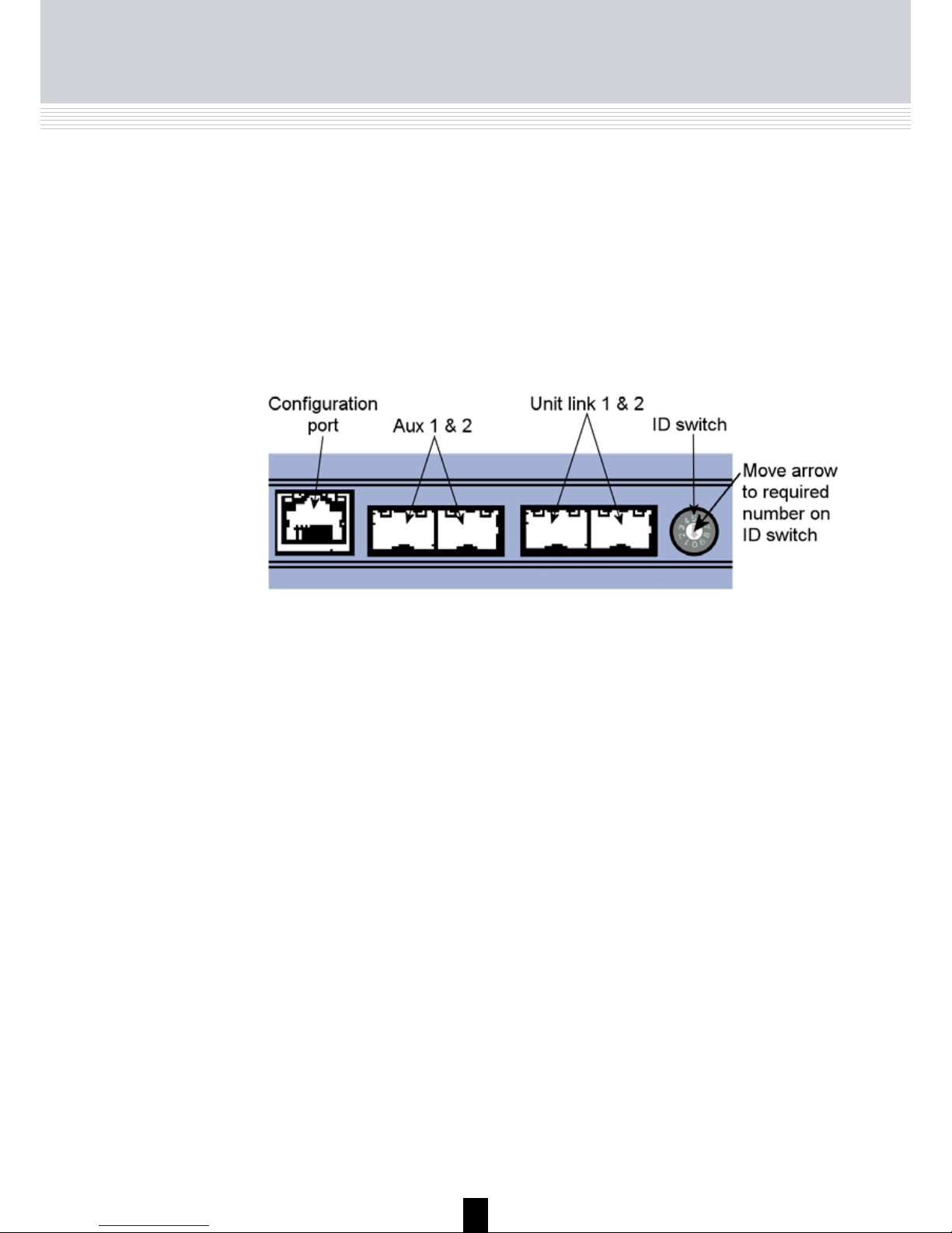
Configuration port
Ethernet configuration port for setting up the headend system. Connector type is RJ-45 and cable type
is Cat7. Use a computer/laptop with the software
recommended below to configure the system.
Recommendations:
Operating system: Windows XP or above.
Browser: Windows Internet Explorer version 6.0 or
above.
Additional software: Microsoft© Silverlight Runtime
version 3.0 or above.
Aux 1 & 2
For future use.
Unit link 1 & 2
Connects the main unit with subunits 1 and 2.
Unit ID switch
Switch for setting the ID of the main unit and the two
subunits.
Note
When you attach F-connectors to the RF
output and Test point sockets you have to be
very careful when you tighten the F-connectors or you may destroy the sockets.
Secure Digital (SD)
card
Memory card for storage of the system configuration. Placed in a slot behind the front cover.
Page 8
8
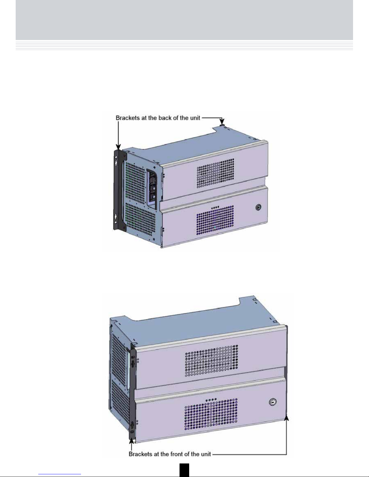
Mounting
Depending on whether you want to mount the headend unit in a rack or on a
wall you have to position the brackets accordingly on the headend unit.
To mount the headend unit on a wall, screw the brackets to the back of the
unit before you mount it.
To mount the headend unit in a rack, screw the brackets to the front of the
unit before you mount it.
Mounting the Unit
Page 9
9
Input modules
It is possible to install up to 16 input modules in a headend unit.
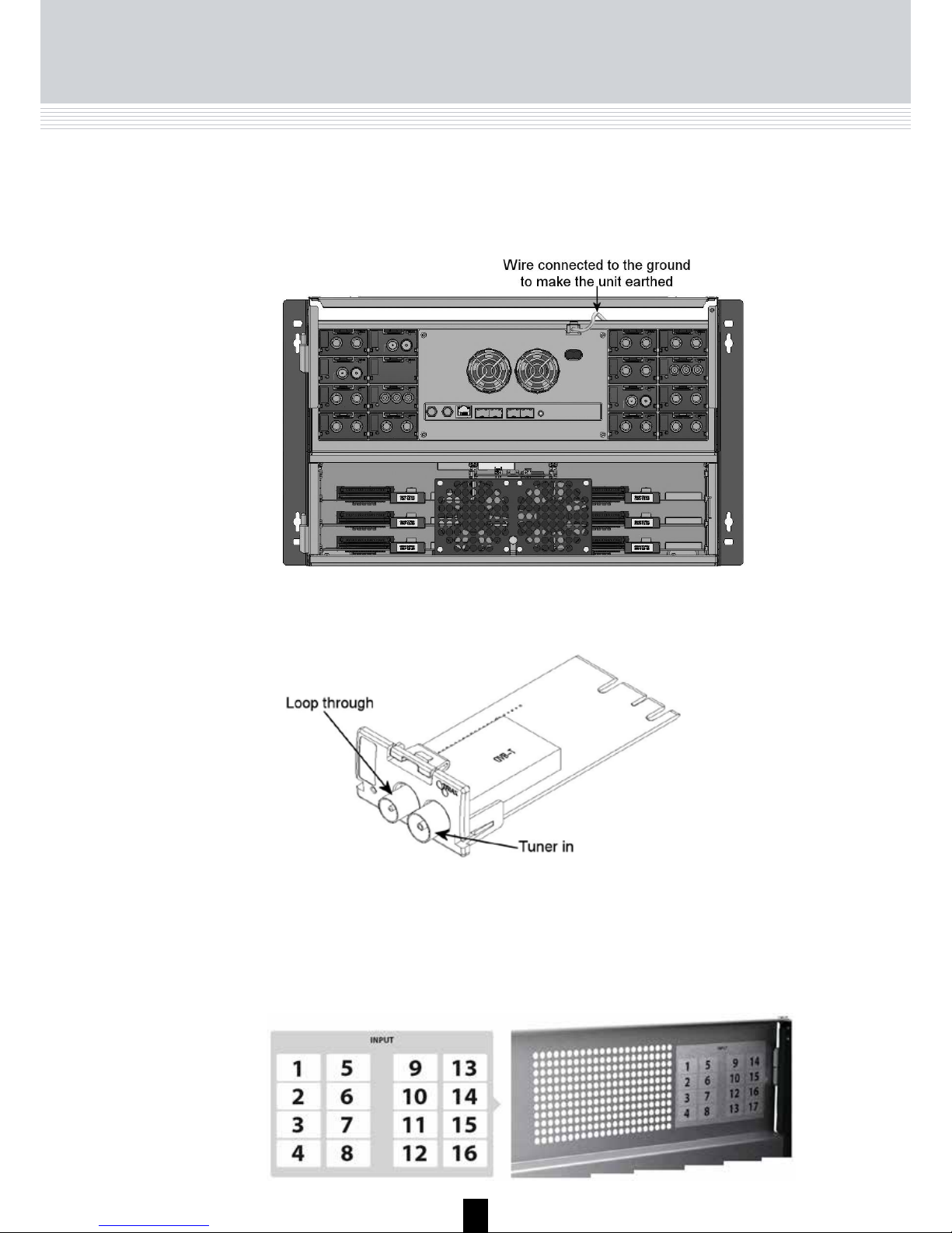
Earthing/Input
Earthing
The headend unit must be earthed before you install any modules, i.e. you
have to connect each headend unit to the ground with a wire from the Earth
terminal socket.
It is optional in which slots you place the individual input modules in the input
section. For convenience each slot has been given a number. An overview of
the slot numbers has been placed on the inside of the door of each unit.
Note
Slot no. 1 is placed in the top left-hand corner of the input section
when you face the front of the unit.
Page 10
10
Input
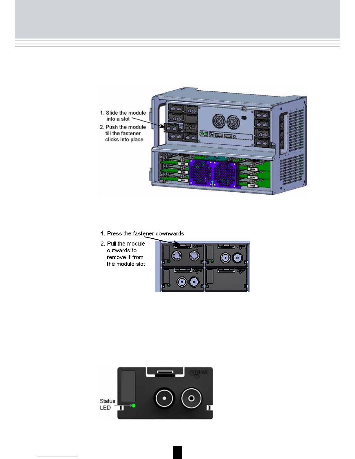
Each input module has a LED on the front to signal whether the module is
locked or not to the frequency that it is set to receive at.
You can remove an input module from a module slot without using any tools,
just use your fingers.
You install an input module by sliding the module into a module slot in the
upper section of the headend unit and click the module into place.
The module has not been configured yet.
Green - flashing
No errors and the tuner is locked to the frequency.
Green
Error and the tuner is not locked to the frequency.
Red
Power has not been switched on.
No colour
When you update the software of a module the status LED provides you with
information about the updating process.
Page 11
11
Input
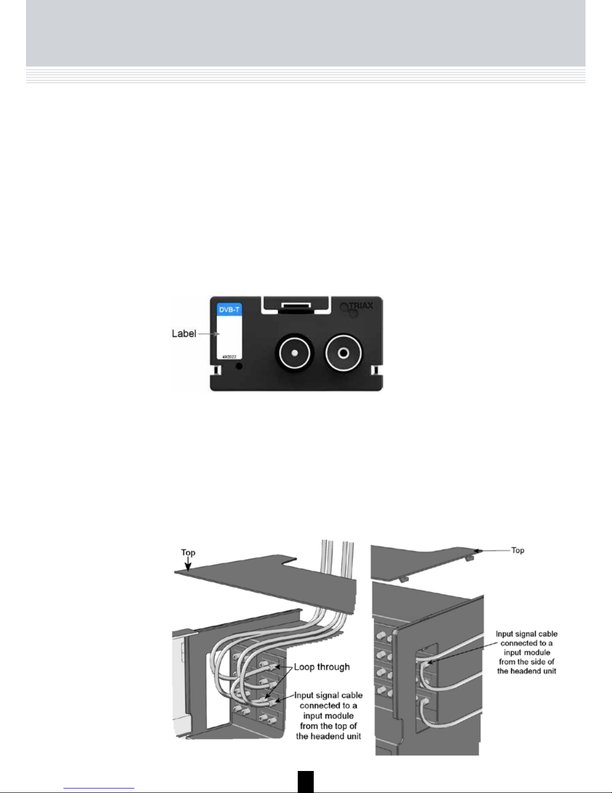
A label is provided on the input module where you can write the information
regarding the configuration of the module.
Besides the information that you write on the label, the module type and
code number are also displayed on the label.
When all the required input modules have been installed you can connect
the input signal cables one by one to the input modules. It is also possible to
make a loop through from one input module to another using a cable.
When connecting the input signal cables you have to decide whether you
want the cables to go from the top of the headend unit to the input modules
or from the side of the unit to the modules.
Boot loader state.
Orange
Initiation of the software update.
Temporary off
Every time the modules receives a valid data package.
Repeated until the update is completed without errors.
Temporary green
Software update failed.
Red
The coloured part of the label informs you of the module type. Each type of
module is allocated a unique coloured label.
On the bottom of the module you will find a label with the bar code and a serial number printed on it.
Page 12
12
Output
Output
modules
It is possible to install up to 6 output modules in a headend unit. Each output
module consists of 4 RF channels. Depending on the type of module you can
add up to 2 CAM modules on each output module.
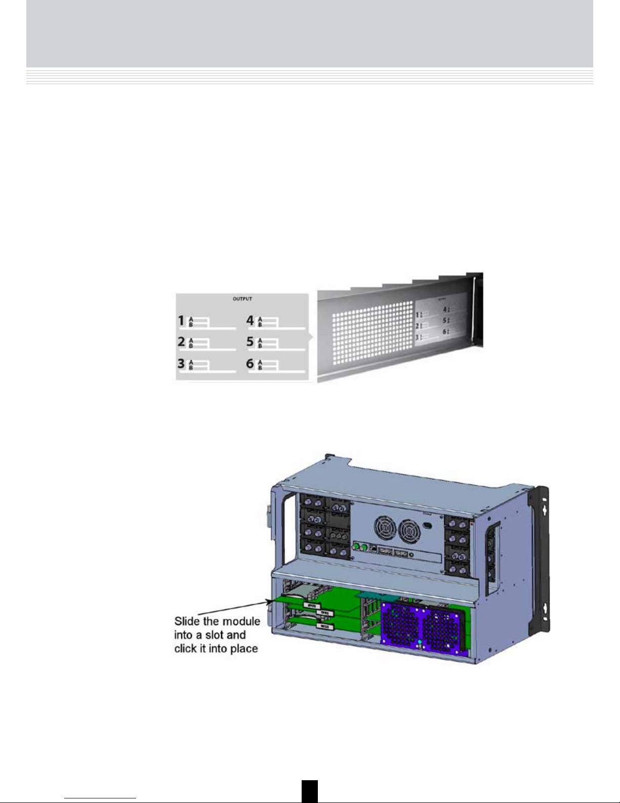
It is optional in which slots you place the individual output modules. For
convenience each slot has been given a number, and an overview of the slot
numbers has been placed on the inside of the door of each unit.
Note
Slot no. 1 is placed in the top left-hand corner of the output section
when you face the front of the unit.
In the future it may also be possible to add an Aux module (for future options)
to the output section.
You install an output module by sliding it into a slot in the lower section of the
headend unit and click it into place.
Note
You can use hot swapping when you insert a module into or remove a module from the TDX system.
Page 13
13
Output
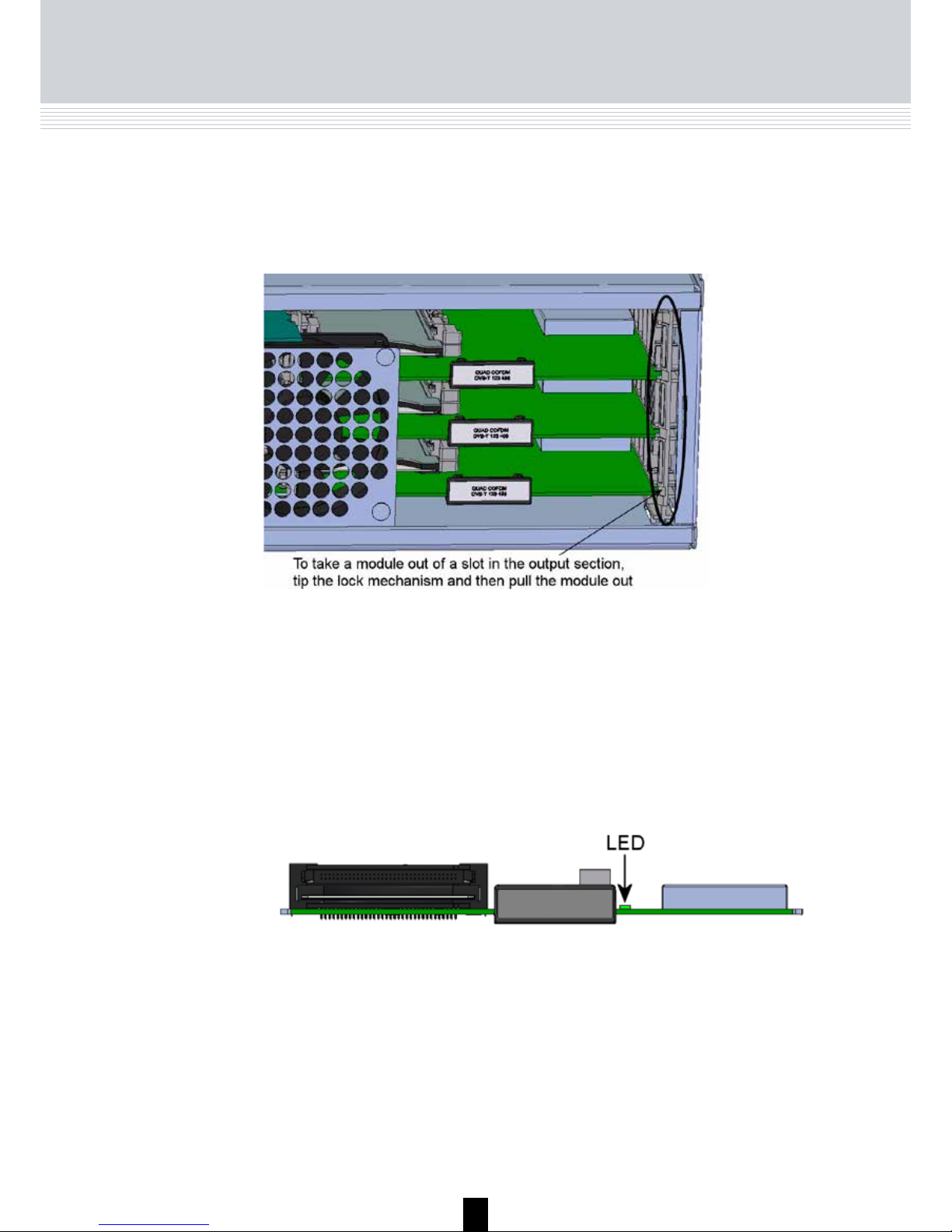
Move the lock mechanism slightly to release the module.
Each output module has a LED on the front to signal whether the module
functions according to its purpose.
You release an output module from a slot by using the lock mechanism that
is placed to the right of the modules in the output section.
When you update the software of a module the status LED provides you with
information about the updating process.
Boot loader state.
Orange
Initiation of the software update.
Temporary off
Every time the modules receives a valid data package.
Repeated until the update is completed without errors.
Temporary green
Software update failed.
Red
The module has not been configured yet.
Green - flashing
No errors and everything is valid.
Green
Error.
Red
Power has not been switched on.
No colour
Page 14
14
Output
CAM/Smart
card
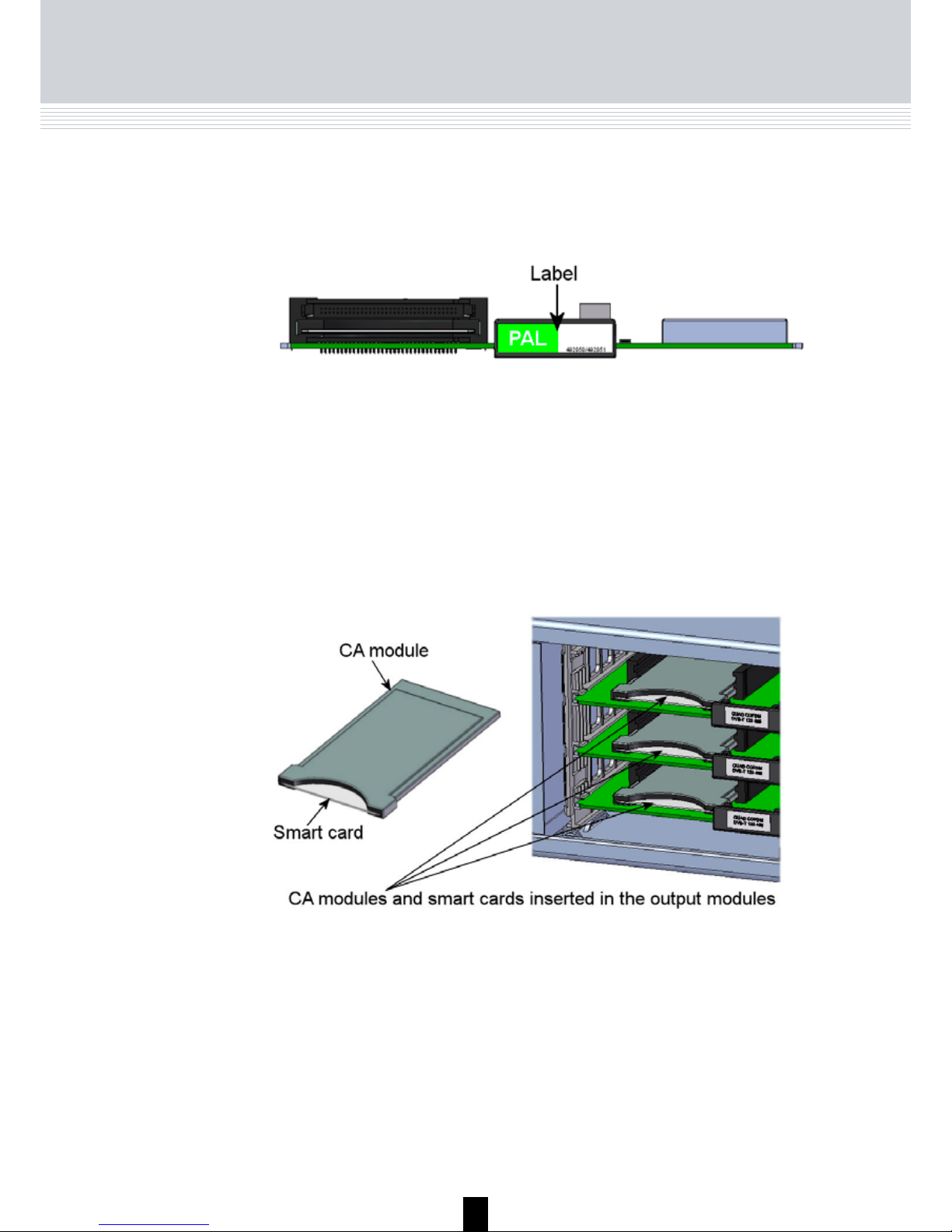
You can insert 2 Conditional Access modules (CA) into each of those output
modules that have CI slots. Each CA module is able to unscramble at least
one service. Which services depend on the service provider of the CA module and smart card.
Small
Form-factor
Plugable
(SFP)
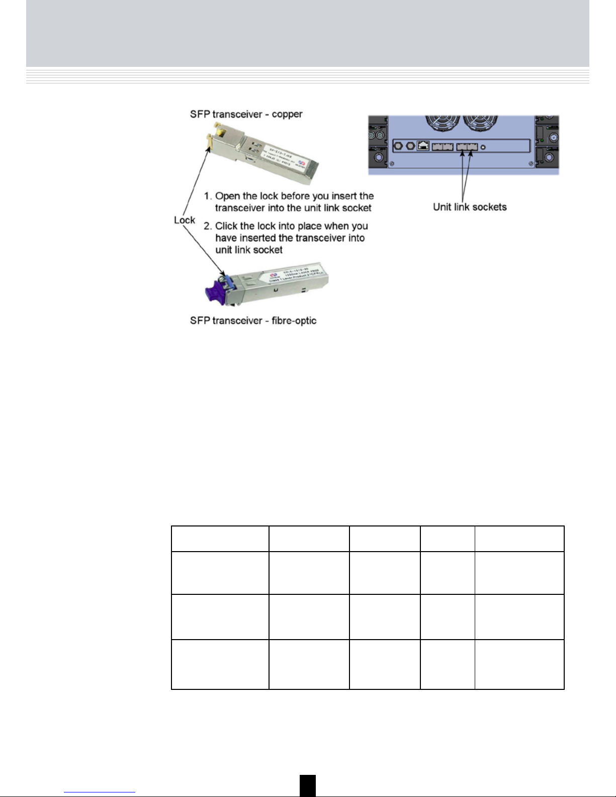
Before you can connect the main unit with any subunits you have to insert
SFP copper or SFP fibre-optic transceivers into the unit link sockets on both
the main unit and the subunit/s.
When you insert an SFP transceiver into a unit link socket you have to open
the lock mechanism on the transceiver before you insert it into the unit link
socket.
Click the lock mechanism into place to lock the transceiver in the socket.
A label with the bar code, serial number and address printed on it is placed
elsewhere on the module.
A label is provided on the output module where you can write the information regarding the configuration of the module. The module type and code
number are printed on the label.
Page 15
15
Note
You also have to insert SFP copper or SFP fibre-optic transceivers into the unit link sockets on the main unit if you want to use the
sockets to output services using an IPTV system.
Connecting units
Connecting
units
To connect the main headend unit with one or two subunits you pull Cat5 or
better cables (SFP copper transceiver) or 850 or 1310 cables (depending on
the SFP fibre-optic transceiver) from one unit to another following the guidelines in the table below regarding the maximum length of the cables.
Part Package Data rate Reach Application
492086
EOLT-C12-02
Copper SFP
(RJ45)
1000Mbps 100m Gigabit Ethernet
via Cat5 cable
492087
EOLS-8512-MXX
Fiber (850nm)
(LC)
1000Mbps 550m Gigabit Ethernet
492088
EOLS1324_02XX
Fiber (1310nm)
(LC)
1000Mbps 2km Gigabit Ethernet
Note
Triax recommend you to use shielded Cat cables.
Page 16
16
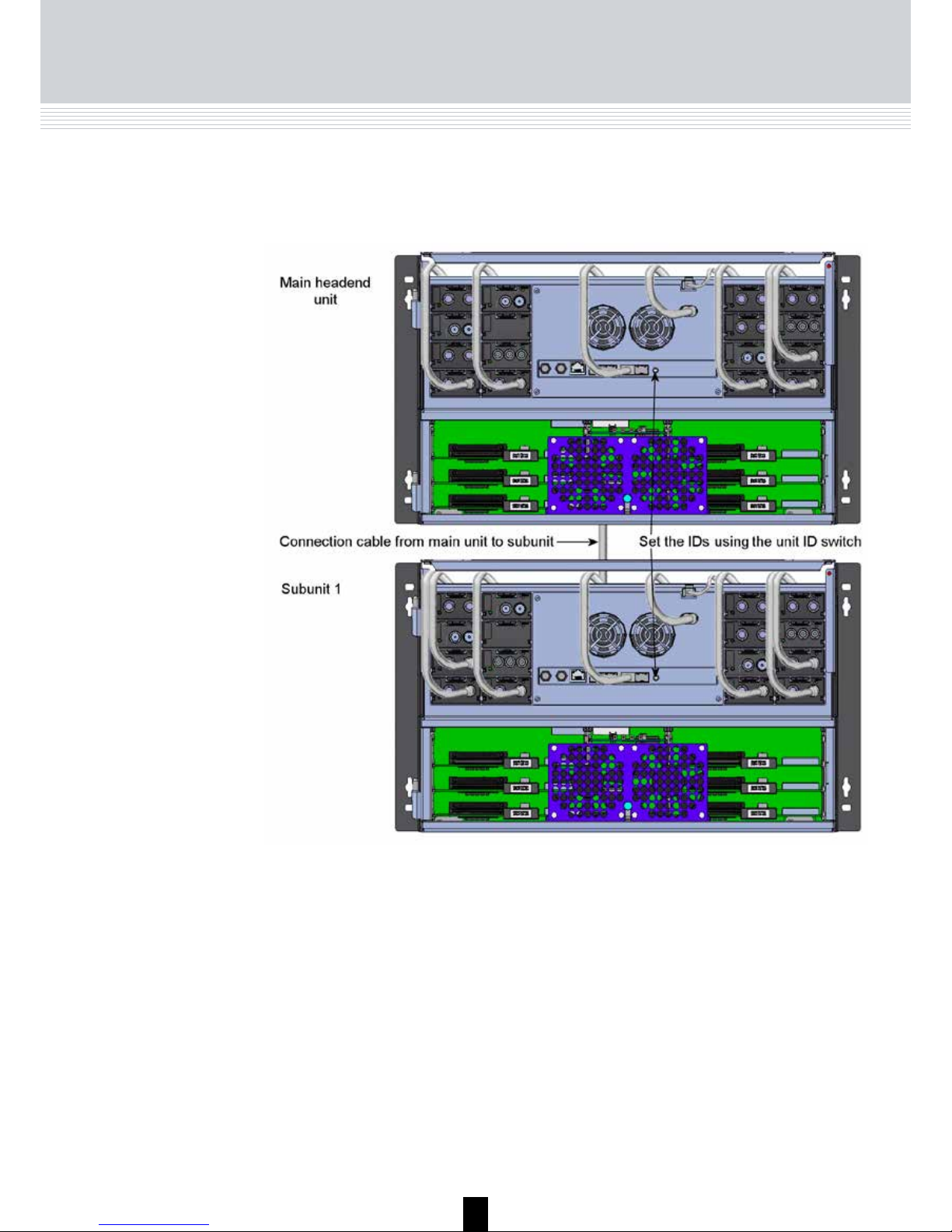
If you only connect one subunit to the main unit, you pull a cable from the
“unit link 1” socket on the main unit to the “unit link 1” socket on the subunit.
Connecting units
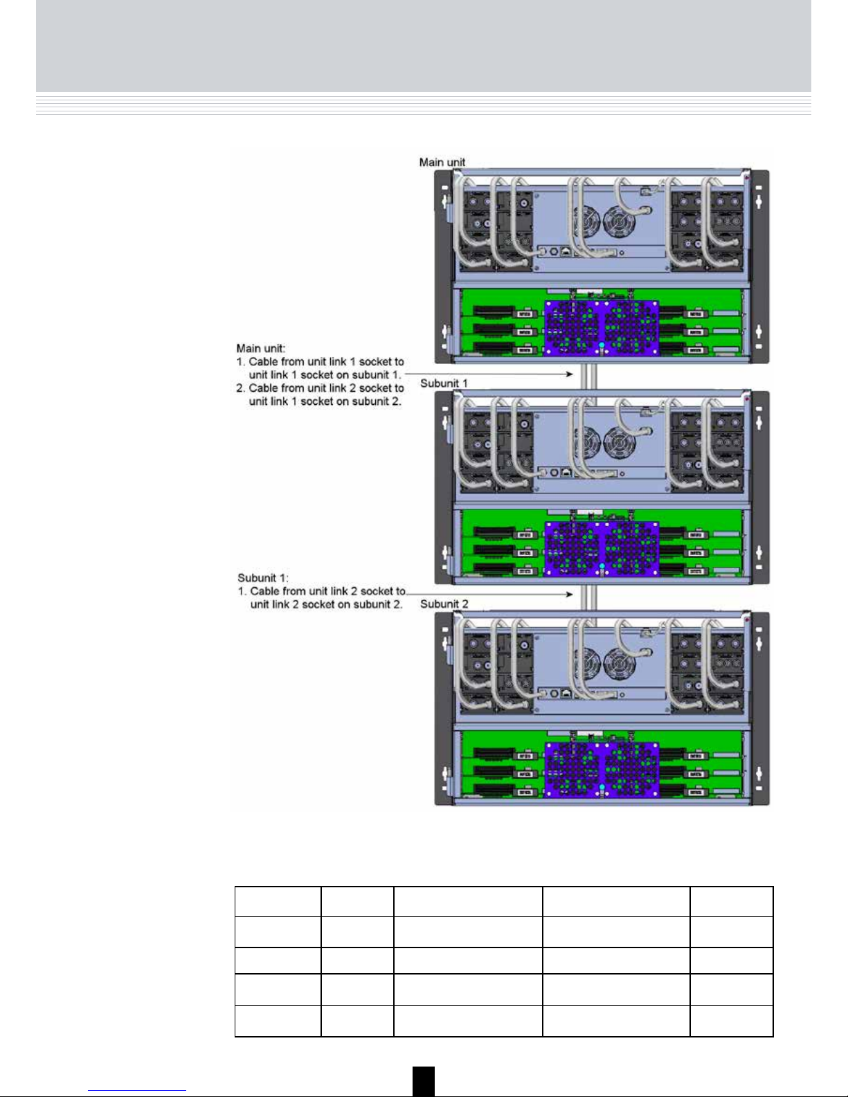
To connect two subunits to the main unit, you pull a cable from the “unit link
1” socket on the main unit to the “unit link 1” socket on subunit 1.
Then you pull a cable from “unit link 2” socket on the main unit to the “unit
link 1” socket on subunit 2.
Next you connect the first subunit to the second subunit using the “unit link
2” sockets on subunits 1 and 2.
Page 17
17
Connecting Units
Eth0 Unit link 1 Unit link 2 ID Switch
Single unit To PC IPTV out IPTV out 0
Main unit To PC Connect to subunit 1 Connect to subunit 2 3
Subunit 1 Not used Connect to main unit Connect to subunit 2 1
Subunit 2 Not used Connect to main unit Connect to subunit 1 2
The table below sums up some of the information from the previous pages.
Page 18
18
When you have connected the main unit and the subunits, you have to set
the IDs of the main unit and the subunits using the “unit ID switch” on the
units.
You set the main unit to “3”, subunit 1 to “1” and subunit 2 to “2”.
ID switch
You have to use a small screwdriver to move the arrow on the ID switch to
the required ID number.
ID Switch
• Switch off the power to the main unit.
• Set the ID switch on the main unit to “7”, then switch on the power.
The four LEDs flash red and yellow until the process of resetting the IP
address has been completed.
If the reset process has been successful the LEDs will turn green.
If the reset process fails the LEDs will turn red.
• Switch off the power to the main unit.
• Set the ID switch on the main unit back to the initial setting.
• Switch on the power to the main unit.
In case you need to reset the IP address of a headend unit, i.e. to return to
the factory default address, you use the ID switch.
To return to factory default settings do the following:
Note
If your headend system consists of only one unit you have to set the
ID of the unit to“0”.
Now you have reset the IP address to the factory default address.
For information about how to change a default IP address, see “IP settings”
on page 33.
Page 19

19
Power and
RF output
Connect each headend unit to a combiner using RF cables from the RF output socket to the combiner.
Next you connect each headend unit to the mains with a power lead from the
power socket to the mains.
Power & RF
Page 20

20
LEDs
To indicate the state of the headend system and the individual units, four
LEDs are placed at the top of the output section of each TDX unit.
The fourLEDs have separate functions.
The colours of the LEDs can be green, green - flashing or red. The message
delivered by the colour depends on the function of the individual LEDs.
System status
• Green: Power is on and the headend system is up
and running.
• Green - flashing: The headend system is booting.
• Red: An error has been detected in the headend
system and it must be investigated. Use the System
information window as starting point for locating errors. For information about System information, see
“System information” on page 25.
LEDs
Tuner status of
input modules
• Green: The tuners are locked.
• Red: One or more tuners are not locked.
Unit link 1
• Green: The subunit is connected to the main unit.
• Red: There is a problem with the connection to the
subunit.
• No colour: No subunit is connected to the main unit.
Unit link 2
• Green: The subunit is connected to the main unit.
• Red: There is a problem with the connection to the
subunit.
• No colour: No subunit is connected to the main unit.
Page 21

21
LED 1 LED 2 LED 3 LED 4
Stand-alone
unit
System state State of input
modules (system)
Always off Always off
Main unit System state State of input
modules (system)
Link 1 state Link 2 state
Subunit 1 System state State of input
modules (unit)
Link 1 state Link 2 state
Subunit 2 System state State of input
modules (unit)
Link 1 state Link 2 state
The table below sums up the type of information that the four LEDs display
on the different units.
LEDs
Page 22

22
Configuration
Configuration
of system
In order to set up and configure the modules within the headend system you
have to connect your laptop (Windows based) to the RJ45 socket on the
main headend unit using a Cat7 cable.
To access the TDX Service Tool, open your web browser on your laptop and
input the following IP address in the web address bar http://192.168.0.100
and press enter.
The Triax TDX Digital Headend system uses the programs below and in addition to access the TDX Service Tool Microsoft© Silverlight Runtime version
3.0 is required.
Recommendations:
Operating system: Windows XP or above.
Browser: Windows Internet Explorer version 6.0 or above.
Additional software: Microsoft© Silverlight Runtime version 3.0 or above.
Your laptop has to use a static IP address in order to access
the TDX Service Tool using the above mentioned IP address.
Note
Page 23

23
Log in
When you have loaded the TDX Service Tool from the TDX headend system
to your laptop/computer the Login window of TDX Service Tool is displayed.
The first time you want to log in to your TDX headend system you have to
enter the default password. The default password is: triax1234
You can change the default password as soon as you have logged in to your
headend system. More information about changing passwords, see “Password settings” on page 31.
When you have pressed the Log in button the System window is displayed.
Every time you set up a new headend system you have to start
from scratch in the TDX Service Tool, meaning that you will have
change the default password, select which language you want to
use in the TDX Service Tool and change the IP address if your TDX
headend system is part of a distribution network.
Note
Log in
Page 24

24
System window
The System window contains a number of tabs and buttons, information
about connected units and a configuration list area.
Via the tabs you enter the different stages of
setting up your input and output modules.
This list displays whether any subunits are connected to the main headend unit and also whether
they are up and running.
This list area will display your present configuration
of your headend system as well as the previous
versions of the configuration.
Configuration list
area
System information
list
Buttons
Tabs
Informs you when the communication between the
TDX system and theTDX Service Tool fails.
Communication icon
System window
In connection with every new headend system the System
window in the TDX Service Tool will display an empty
configuration list area.
Note
You use the buttons in the upper right-hand corner
in connection with the TDX Service tool whereas
you use the buttons below the configuration list
area in connection with the entire setup itself.
Page 25

25
System window
In the System information window you get information about system errors,
which software version each of the input and output modules uses and the
MAC addresses.
In connection with errors in your TDX headend system you can use the
System information window as starting point for locating the errors.
System
information
To get detailed information about the individual units you can click the unit
in question in the System information list and open the System information
window.
Page 26

26
Green: The TDX Service Tool and your TDX headend system exchange
information without any problems.
Communication
icon
The colour of the communication icon tells you when TDX Service Tool is not
communicating properly with the TDX headend system.
Red: The TDX Service Tool and your TDX headend system are not
communicating properly. Press the F5 button to refresh the internet browser
and renew communication between the TDX Service Tool and the headend
system.
To change password and language you have to open the Administration
window by clicking the Admin. button in the top right-hand corner of the
System window.
Administration
window
Click the Admin. button to open the Administration window.
System window
Page 27

27
Administration window
Language
settings
When you have opened the Administration window the Language settings
area is displayed.
To select another language, click the arrow to the right of the Current
language field to open the drop-down list with the languages you can
choose from.
Select the language you want to use in the TDX Service Tool.
The language you selected is now displayed in the Current language field.
Page 28

28
Country settings
Now you can see the fields of the Country settings area.
To enter the Country settings area, click the arrow bracket to the left of
Country settings.
To set the location of your TDX headend system, click the arrow to the right
of the Country field to open the drop-down list with the countries you can
choose from.
Settings
Page 29

29
Settings
Time zone
settings
To enter the Time zone settings area, click the arrow bracket to the
left of Time zone settings.
Select the country in which your TDX headend system is located.
The country you selected is now displayed in the Country field.
Page 30

30
To set the time zone of your TDX headend system, click the arrow to the
right of the Time zone field to open the drop-down list with the time zones
you can choose from.
To set time in accordance with the time zone, click the arrow to the
right of the Input module field to open the drop-down list with all the
input modules installed in your main unit.
Select the time zone you want to use in connection with your TDX
headend system.
The time zone you selected is now displayed in the Time zone field.
Settings
Page 31

31
Settings
Select the input module you want to use for setting the time. The input
module you selected is now displayed in the Input module field.
To enter the Password settings area, click the arrow bracket to the left
of Password settings.
Password
settings
To verify the new password enter the new password once more in the
Confirm password field.
To change password enter the old password in the Old password field.
Enter the new password in the New password field.
Page 32

32
If you have bought licences to output services using e.g. IPTV you have to
activate these licences in your TDX headend system using Licence handling
in the Administration window.
To enter the Licence handling area, click the arrow bracket to the left of
Licence handling.
Before you can activate a licence you have to contact Triax and provide
information about the serial number displayed in the Serial number field
and the ID displayed in the TDX unique ID field.
When Triax has received the ID of your TDX they will provide you with the
activation key.
Enter the activation key in the Activation key field then click the Activate
button to access the licence you have bought.
Licence handling
Settings
Page 33

33
Settings
IP settings
When you have clicked the Activate button to access your licence
your TDX unique ID is changed and the activation key is deleted.
Note
When you have accessed your licence you use e.g. the IPTV tab to select
the services you want to output in connection with the licence.
If you want to buy more licences you will have to contact Triax
with the new TDX unique ID to Triax to get a new activation key
to access an additional licence.
If your TDX headend system is part of a network you have to change the I
P address of the configuration port to include the main unit in the network.
To enter the IP settings area, click the arrow bracket to the left of IP settings.
Page 34

34
Enter a new IP address, subnet mask and default gateway in the
corresponding fields.
Note
In case you need to reset the IP address to the factory
default address, you have to use the ID switch.
For information about how to use the ID switch to reset
the IP address, see “ID switch” on page 18.
Important
To make a changed IP address take effect you have to r
eboot the TDX headend system using the Reboot button
in the System maintenance area or switch off the power.
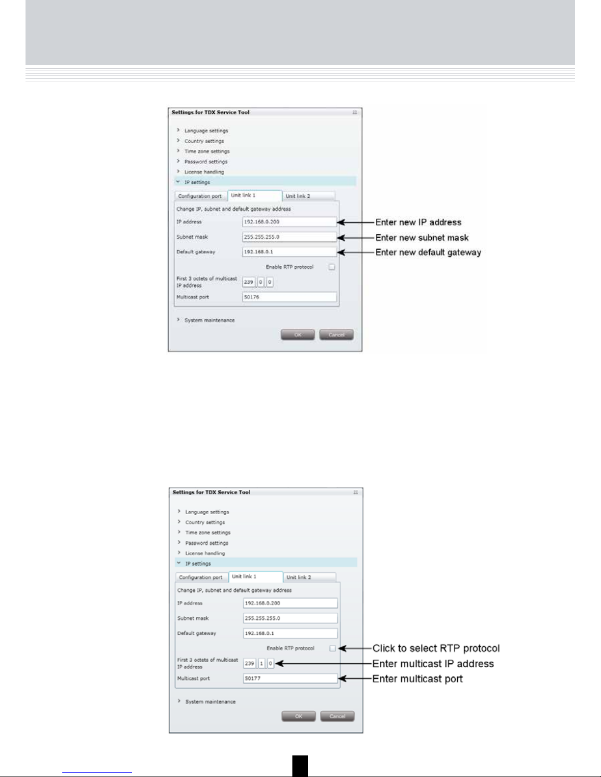
To output services using an IPTV system or to include a subunit in a network
you have to enter an IP address, subnet mask and default gateway for each
unit link socket you use.
To enter the IP settings area, click the arrow bracket to the left of IP settings.
Now click the Unit link 1 tab to display the relevant fields.
With regard to IPTV you also have to enter a multicast IP address and a
multicast port for each unit link socket you use.
Enter a new IP address, subnet mask and default gateway in the
corresponding fields.
Settings
Page 35
35
Settings
In case you cannot use the default values displayed in the two fields, enter
a new multicast IP address and a multicast port in the corresponding fields.
Click the Enable RTP protocol check box if you want to use Real-time
Transport Protocol in your IPTV system.
In connection with IPTV the fields at the bottom of the area are needed as
well.
Page 36

36
When you have made the changes you want to make in the Administration
window, click the OK button at the bottom of the Administration window
to save the changes and return to the System window.
Save settings
Click the Unit link 2 tab if you have connected an IPTV system or a second
subunit to the Unit link 2 socket and enter an IP address, subnet mask and
default gateway and in connection with IPTV also a multicast IP address and
a multicast port.
Important
To make a changed IP address take effect you have to reboot
the TDX headend system using the Reboot button in the
System maintenance area or switch off the power.
Note
You only need to change password, language, time zone,
country and IP addresses the first time you enter a new TDX
headend system in order to set it up.
Settings
Page 37

37
System configuration
Create a
new system
configuration
To create a new configuration, click the New configuration button in the
System window.
Now a configuration file is created and the file is listed in the configuration
list area.
Click this button to download a configuration file from your
computer/laptop to your TDX system. More information
about downloading, see “Load to TDX” on page 54.
Click this button to upload the configuration file from the
TDX system to your computer/laptop. More information
about uploading, see “Load from TDX” on page 55.
You use the buttons below the configuration list area to manage
configuration files in your headend system.
Click this button to delete a selected configuration file.
Click this button when you want to activate a selected
configuration file.
Delete
Load to TDX
Load from TDX
Set active
Click this button to create a new configuration file.
New
To activate a new configuration file, select the file and click the Set active
button, and the Apply button to save the configuration file.
Page 38

38
Change system
configuration
When you change an existing configuration of your headend system the
TDX Service Tool updates the date and time of the configuration file when
you save the changes using the Apply button.
Apply
An important button when you change your configuration of the headend
system is the Apply button placed in the upper right-hand corner of the TDX
Service Tool window.
Save
configuration
Whenever you have made changes in your configuration,
“Apply” on the Apply button turns red to tell you that
you have unsaved changes that need to be saved.
Click the Apply button to save the changes. When
changes have been saved the “Apply” text looses the
red colour.
System configuration
Page 39

39
IPTV
IPTV window
To output services using IPTV, click the IPTV tab in the TDX Service Tool to
display the IPTV window.
The first time you display the IPTV window in a new configuration the list
areas below "Link 1" and "Link 2" representing the unit link 1 and 2 sockets
on the main unit will be empty.
To display the Configuration window, click the Setup button of the unit link
socket to which your IPTV system is connected.
The TDX headend system includes basic IPTV functionality which enables
you to deliver services using the architecture and networking methods of the
Internet Protocol Suite over a packet-switched network infrastructure, e.g.
the Internet and broadband Internet access networks.
Page 40
40
IPTV
configuration
window
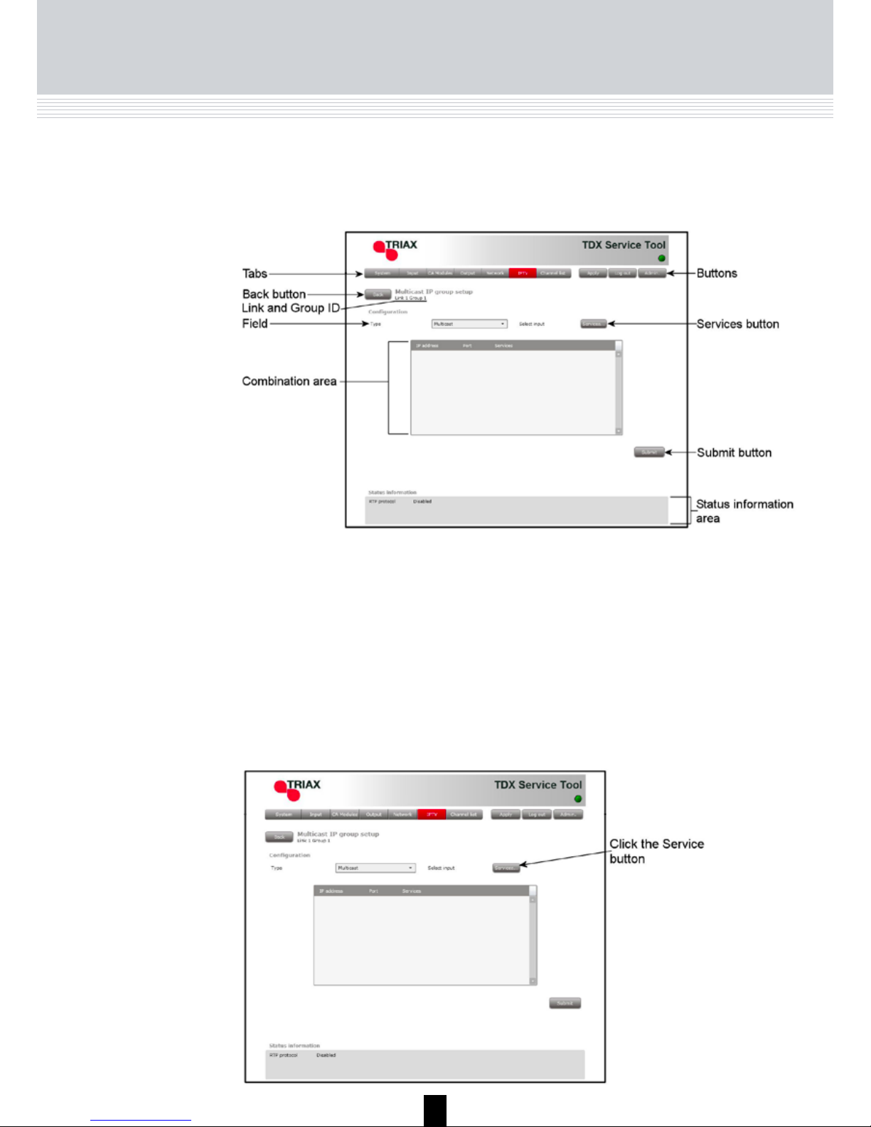
The first time the TDX Service Tool displays the Configuration window in a
new configuration the fields in the window will either display a default value
or be empty.
Type
To select the desired type of communication, click the
arrow to the right of the Type field to open the dropdown list with the types you can choose from.
Select the type you want to use.
Select input
To select services, click the Services... button next to
Select input label to open the Select services window.
Note
If you have selected “Multicast” in the Type
field you can only output one service on each
IP address.
IPTV
Page 41

41
IPTV
In the Select Services window you can select the service that you want to
output.
Click OK to return to the Configuration window when you have selected the
services you want to output.
To select one or more services, click the check box (square) to the right of
the service you want.
Page 42

42
Note
When you have selected a service this service will no longer
be available in the TDX-pool for the unit link in question.
In the Configuration window the combination area displays the services
you have selected and the IP addresses that have been allocated to each
of the services.
If you have selected more services than your licence(s) entitles you to select,
you will get a warning and the services that exceed the number of services
you can select will be deselected
It is possible to change the last digits of the IP address if for example you
want to change the order of the services.
To change the last digits of the IP address, click the field, delete the
existing digit(s) and enter the new digit(s).
Note
You can change the first digits of the IP address in the IP
settings area in the Administration window.
IPTV
Page 43

43
IPTV
When you have selected the services you want you have to click the Submit
button to enter this information in to the headend system and return to the
Output window.
Remember to click the Apply button in the upper right-hand corner to save
new settings in the configuration.
Status information is placed at the bottom of the Configuration window.
The information displayed in the configuration window includes RTP
protocol and services.
Services used
RTP protocol
Informs whether or not you have enabled RTP in the IP
settings menu in the Administration window.
Status
information
Tells you how many services out of the total number
services your licence gives you access to you have
output so far.
Page 44

44
IPTV
When you return to the Output window the configuration of the unit link1
socket is displayed in the IPTV list.
If your licence(s) gives you access to select a large number of services it is
possible to group the services in the IPTV list in order not to lose control of
which services you have selected.
To configure a new group of services, click the Setup button to open the
Configuration window. Select a number of services in the Configuration window, click the Submit button to enter this information in to the headend system and return to the Output window which will display the new group.
If you want to remove a group of services and the associated configuration
you can use the Delete button of the group in question in the IPTV window.
Click the Delete button of the group you want to remove. A message window
is displayed asking you to confirm that you want to remove group.
Delete IP group
Page 45

45
Log file
To save a log file on your computer/laptop you have to open the Administration window.
Log file
You can save a log file that lists actions that have occurred in the TDX headend system. This may be useful in case of problems with your TDX headend
system.
The size of the log file will be adequate for listing all actions that have occurred in the system for a couple weeks.
Click the Admin. button in the top right-hand corner of the TDX Service Tool
window to open the Administration window.
To enter the System maintenance area, click the arrow bracket to the left of
System maintenance.
Page 46

46
Log file
In case you need to save the log after having looked at the file in the
Notepad window you can use the Save as command in the File menu
of the Notepad window.
In the System maintenance area click the Save log button to open the
File Download window.
In the File Download window you can either open the log file or save the
file to your laptop/computer.
If you only want to save the log file when you open the File Download
window, click the Save button to open the Save as window.
If you want to open the log file click the Open button in the File Download
window.
Page 47

47
Log file
When the log file has been downloaded and saved, you can open the log file,
open the folder where you have saved the log file or just close the window.
Navigate to the folder where you want to place the log file
Click the Save button to save the file.
Clicking the Save button displays the Download window.
When you close the Download window you return automatically to the Administration window. Close this window by clicking the OK or Cancel button.
Page 48

48
Updating firmware
Click the Change... button to the right of the version number of the current
firmware to open the Firmware window.
Update
firmware
When firmware updates for your TDX system is available on the Triax home
page, www.Triax.com, you can download these updates to your computer
and then upload the updates to your TDX system using the Administration
window.
Click the Admin. button in the top right-hand corner of the TDX Service Tool
window to open the Administration window.
To enter the System maintenance area, click the arrow bracket to the left of
System maintenance.
Page 49
49
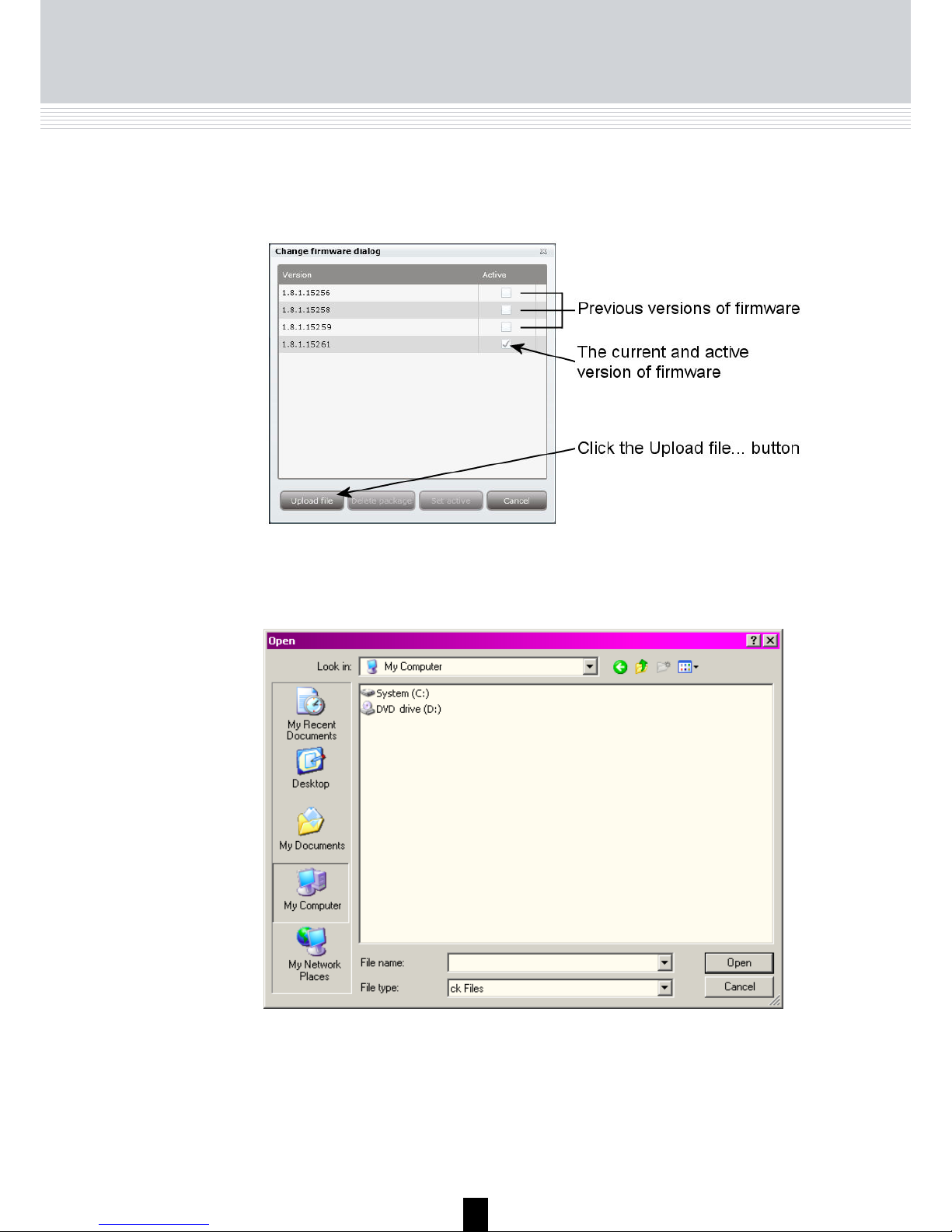
Updating firmware
The Firmware window lists the current version of your TDX firmware as well
as previous versions of the firmware.
Click the Upload file... button to display the Open window.
In the Open window navigate to the folder where you saved the update file
when you downloaded it from the Triax home page.
Select the file.
Click the Open button to include the file in the list in the Firmware window
Page 50

50
Updating firmware
When you have clicked the Open button you return to the Firmware window.
In the Firmware window the new update file is placed at the bottom of the list
of updates.
Click the file name to select the file and then click the Set active button to
transfer the update to the TDX system.
Clicking the Set active button displays the Firmware update window. In this
window you select whether you want to update all firmware, i.e. modules,
system controller and user interface, or only firmware that is in need of an
update.
Triax recommend that you use the Replace all option when you want to update your firmware.
You should only use Update old packages if your TDX headend system consists mainly of new modules and a few older modules that might benefit from
an update.
Page 51

51
Updating firmware
When updating the firmware, the Firmware update status window will display
information about status and errors as well as the progress of the update itself. An update will take approximately 5 minutes.
When you have finished updating the firmware you have to reboot the system by clicking the Restart button in order to make the update effective.
Important
When rebooting the TDX headend system the distribution of
services to all your end-users will be interrupted for a very
short time.
Page 52

52
Updating firmware
When you have rebooted the TDX headend system, a message window is
displayed asking you to restart your Internet browser.
When you have restarted your browser you have to log into the TDX Service
Tool in case you need to make any changes.
If your list of firmware updates needs to be tidied you can remove one or
more of the previous firmware updates listed in the Change firmware window.
Select the firmware update and click the Delete package button.
The firmware update is removed from the list.
Page 53

53
Rebooting
You can also reboot the TDX headend system by switching
off the power manually.
Note
When the TDX system has been rebooted, you close the Administration
window and restart your Internet browser.
Important
When rebooting the TDX headend system or switching off
the power the distribution of services to all your end-users
will be interrupted.
Reboot system
If you need to switch the TDX headend system off and then immediately
start it again you can use the Reboot button in the System maintenance
area of the administration window.
Click the Reboot button to reboot the TDX headend system.
When you have restarted your browser you have to log into the TDX Service
Tool if you need to make further changes.
Page 54

54
Loading
In case you want to load a configuration file made using the TDX Configurator
from your computer/laptop to your TDX system you have to use the Load to
TDX button on the System tab.
Load to TDX
Click the Load to TDX button at the bottom of the System tab to display the
Open window.
In the Open window navigate to the folder where you saved the configuration
file from the TDX Configurator.
Select the file, then click the Open button to include the file in the configuration
list on the System tab.
Page 55

55
Loading
The configuration file will now be listed in the configuration list area.
If the name of the new configuration file is identical to the existing configura-
tion file a number in brackets will be added to the name of the new file.
Load from TDX
You can save a configuration file from your TDX headend system to your
computer/laptop in case you want to use it in another TDX headend system
that is identical to the one from which you want to save the configuration file.
To save a configuration file on your computer/laptop you have to use the
Load from TDX button on the System tab.
If, however, you load a configuration file into a dissimilar TDX system you will
have to reconfigure all those modules that deviate from what is specified in
the configuration file. All deviating modules will be marked in red.
Click the Load from TDX button at the bottom of the System tab to display
the Save As window.
Page 56

56
Loading
Navigate to the folder where you want to save the configuration file.
Enter the name of the configuration file in the File name field.
Select file type in the File type field.
Click the Save button to save the file.
You return automatically to the System tab when you have saved the configuration file.
For information on how to configure the different input and output modules,
please read the associated user guides.
Configuration
of modules
Page 57

57
Technical data
Type
TDX Cabinet - main unit for TDX range of modules
Technical data
Description
The TDX housing is designed to accommodate up to 16 frontend and 6 quad
backend modules. Up to three TDX headends can be combined as one sys
tem of up to 48 input muxes and 72 output channels, either 72 PAL programs
or 72 QAM/COFDM muxes or a mixture of these.
The heart of the TDX is the TDX pool where services are available from all
front end modules, whether terrestrial, satellite or AV encoder. From the pool,
the services can be cherry-picked and distributed via the COFDM, QAM, PAL
or IP backend modules. Any input can be connected to any output.
Features
Better and stronger performance with energy-friendly
and long-term reliability, in a compact housing
Quick installation
Cable management
Hot swap service in TDX system.
Easy set-up with few modules
Product
Art. No.
TDX Main unit cabinet
492090
General
Frequency range (RF OUT) MHz 47-862
Impedance (RF OUT) Ohm 75
Return loss (RF OUT) dB > 14 at 47MHz (-1.5dB/octave; Min. 10dB)
Testpoint dB -20
Output level max @ 60 dB IMD
24 combined channels
dBµV 103
Power Supply
Operating voltage VAC 190-260 50/60 Hz
Min. power consumption W 20
Max. power consumption W 280
Max. LNB control mA 4 x 305
Connectors
AC Power in (1,8m) IEC320 (cable)
Ext. TV-OUT F-con
Ext. testpoint F-con
PC RJ 45
SFP cage 4 x expansion
Environment
Temperature, operating °C -10…+50
Temperature, storage °C -20…+70
Humidity, operating % 20…80
Humidity, storage % 10…90
Mechanical data
Weight - net kg 10.5
Dimensions product ( L x W x H ) mm 440x240x290
Page 58

58
Your notes
Page 59

59
Your notes
Page 60

10 - 2012
Dear Customer,
Should you require technical assistance in the event that your
expert dealer is unable to help you, please contact us at:
Triax A/S
Bjørnkærvej 3
8783 Hornsyld
Denmark
Tel.: +45 76 82 22 00
mail: triax@triax.dk
web: www.triax.dk
DECLARATION OF CONFORMITY
TRIAX confirms that the product conforms to relevant EEC harmonised standards and consequently can carry the CE-mark.
Relevant harmonised standards:
DE/EN 60728-2 2010, DS/EN 60728-11 2010 and DS/EN 50083-2 2006
This document is only valid with the signature of the person responsible for CE-marking by Triax
Date: October 2012 Signature:
Manufacturer
 Loading...