

Page 1
Model Item no.
QAM output module 492055
492056
Version 891076E 12 - 2013 EN
triax.com
User guide
QAM output module
Page 2

2
Rev. 01 - 2014 - E
Contents
Contents
Disposal .................................................................................................................................. 3
Box content ............................................................................................................................ 3
QAM module .......................................................................................................................... 3
Labels ..................................................................................................................................... 4
Installation of module ........................................................................................................... 4
Removal of module ............................................................................................................... 4
CAM/Smart card .................................................................................................................... 5
Status LED ............................................................................................................................. 5
Log in ...................................................................................................................................... 7
CA Modules window ............................................................................................................. 8
CA Modules configuration window ...................................................................................... 9
Delete CA module .............................................................................................................. 15
Event log ............................................................................................................................ 15
Output window .................................................................................................................... 16
Configuration of output modules ....................................................................................... 17
Payload monitor ................................................................................................................. 22
Status information .............................................................................................................. 23
Delete output modules....................................................................................................... 24
Event log ............................................................................................................................ 25
Network window .................................................................................................................. 26
Channel list .......................................................................................................................... 29
Save configuration .............................................................................................................. 30
Your notes ............................................................................................................................ 31
Manufacturer ....................................................................................................................... 32
Page 3
3
Rev. 01 - 2014 - E
Introduction
Disposal
Within in the European Union this label indicates that the product
cannot be disposed of with the general household waste. Neither
the headend nor the input and output modules can be disposed of
with the general household waste.
For proper treatment and recycling of old products, please take
them to designated collection points in accordance with your national legislation.
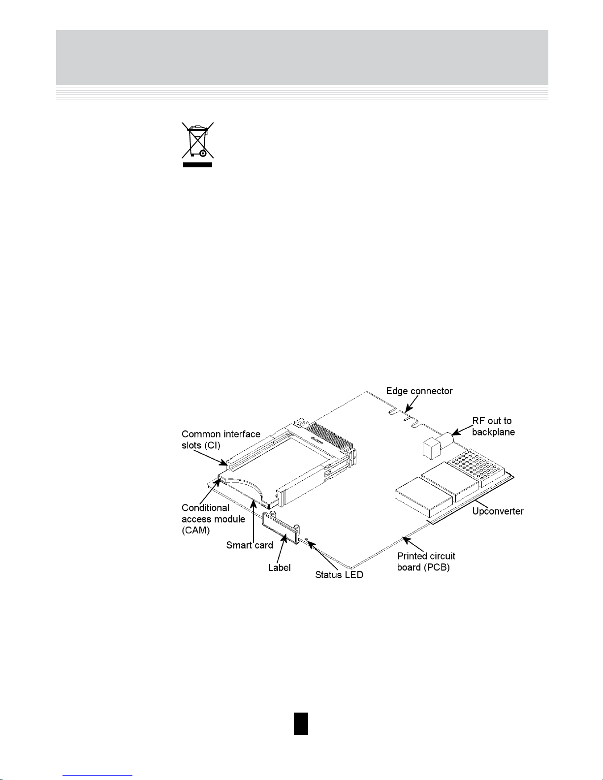
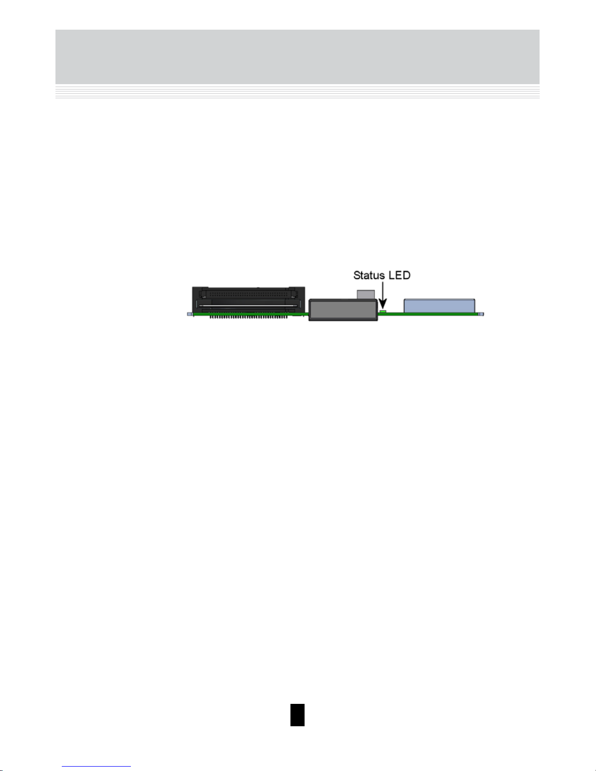
The QAM output module is available in two versions, one version with Common Interface (CI) and one without.
Below you can see an illustrated description of a QAM module with CI slots.
QAM module
Box content
A new output module is wrapped in antistatic bubble wrap and packed in a
cardboard box when you receive it.
Included in the box is a user guide instructing you in how to use the TDX
Service Tool to configure the module.
Page 4
4
Rev. 01 - 2014 - E
Basics
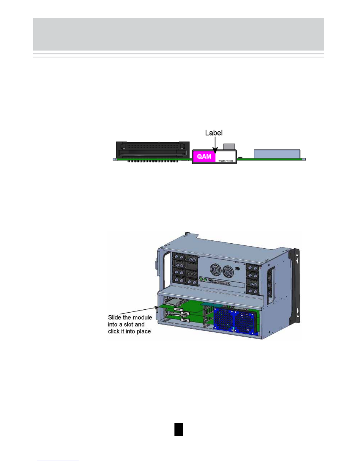
Labels
Installation of
module
You install an output module by sliding the module into a module slot in the
lower section of the headend unit and click it into place.
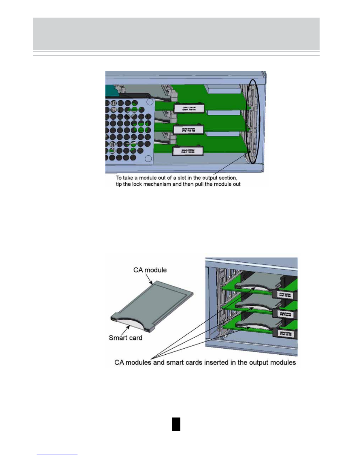
Removal of
module
You release a CI module from a slot by using the lock mechanism that is
placed to the right of the modules in the output section.
Move the lock mechanism slightly to release the module.
A label is placed on the output module where you can write the information
regarding the configuration of the module.
Besides the information that you write on the label, the module type and part
number are also displayed on the label.
Note
The coloured part of the label informs you of the module type.
Each type of module is allocated a unique coloured label.
On the bottom of the module you will find a label with the bar code and a serial number printed on it.
Note
You can use hot swapping when you insert a module into or remove a module from the TDX system.
Page 5
5
Rev. 01 - 2014 - E
Basics
CAM/Smart
card
You can insert 2 Conditional Access modules (CA) into each of those output
modules that have Common Interface (CI) slots.
Each CA module is able to unscramble at least one service. Which services
depend on the service provider of the CA module and smart card.
Status LED
There is a status LED on the front of each module. The LED indicates whether the module functions according to its purpose or fails.
Page 6
6
Rev. 01 - 2014 - E
Basics
When you update the software of a module the status LED provides you with
information about the updating process.
Boot loader state.
Orange
Initiation of the software update.
Temporary off
Every time the modules receives a valid data package.
Repeated until the update is completed without errors.
Temporary green
Software update failed.
Red
The output module receives data.
Green - flashing
The output module receives valid services.
Green - constant on
When starting the TDX system the output module and
the system controller negotiate connection speed. If
the LED continues to be red either the output module
or the system controller has not been inserted correctly.
Red
The output module has not been configured yet or the
module has not been inserted correctly.
No colour
Page 7
7
Rev. 01 - 2014 - E
TDX Service Tool
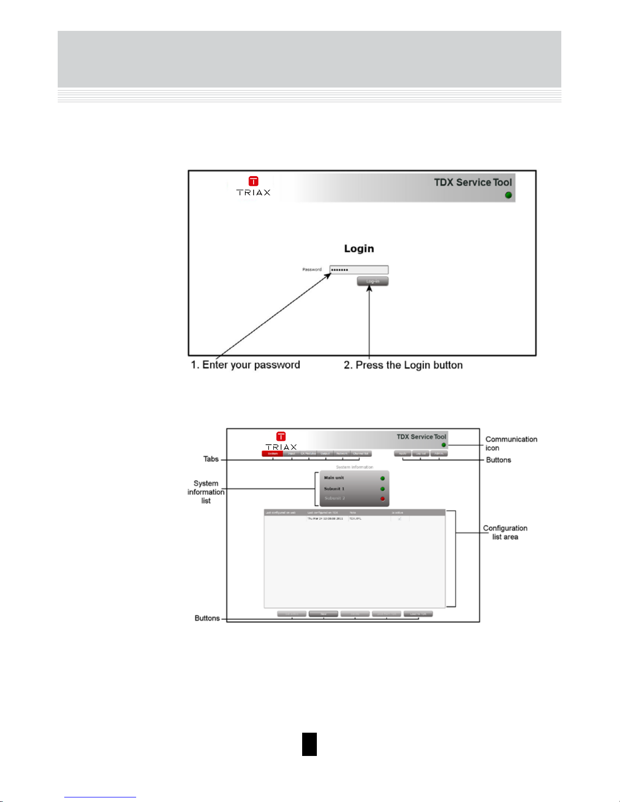
Log in
When you have loaded the TDX Service Tool from the TDX headend system
to your laptop/computer the Login window of TDX Service Tool is displayed.
When you have pressed the Log in button the System window is displayed.
Page 8
8
Rev. 01 - 2014 - E
TDX Service Tool
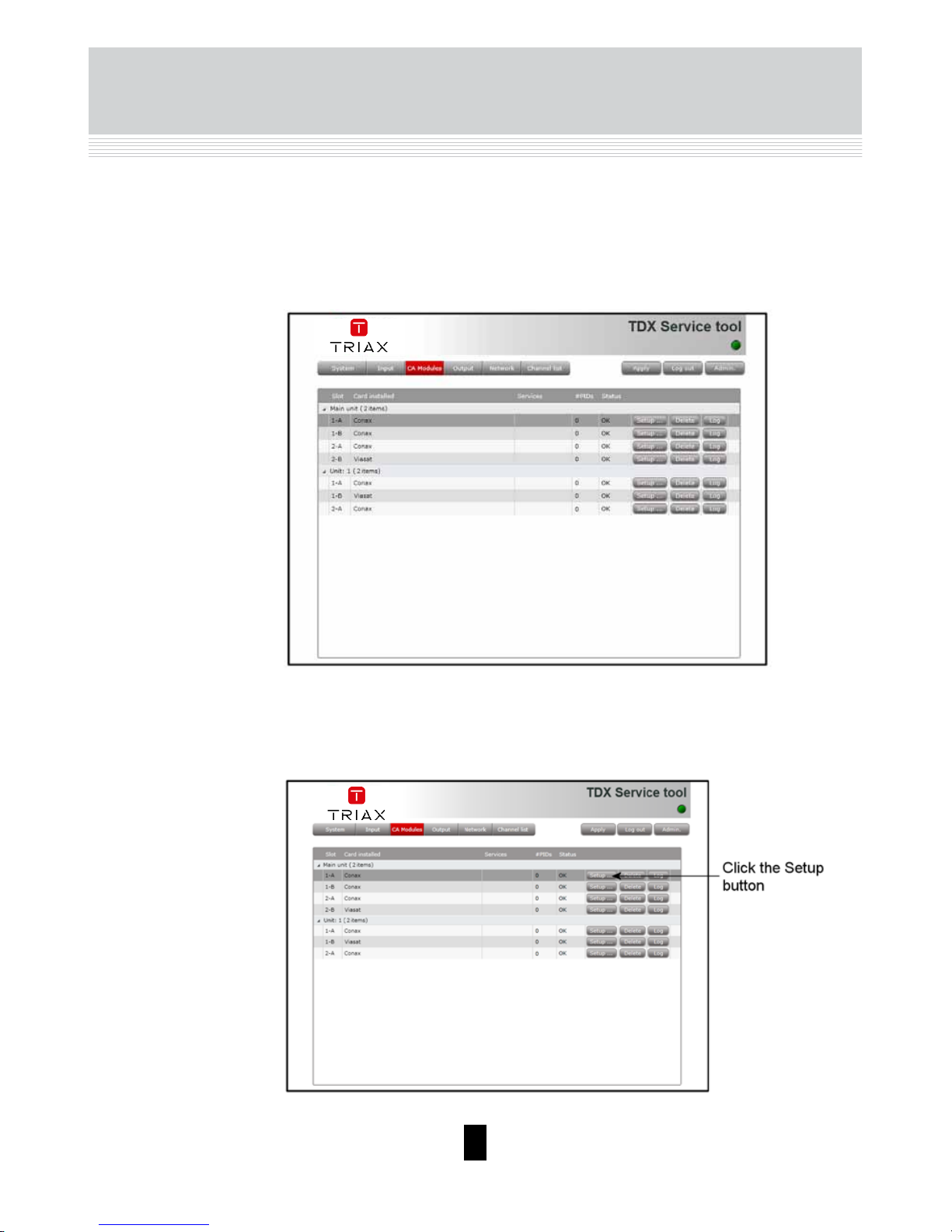
CA Modules
window
Click the CA Modules tab in the TDX Service Tool to display the CA Modules
window.
The first time you display the CA Modules window in a new configuration the
module list only displays the number and type of the CA modules that you
have inserted in the main and subunits.
You have to configure the CA modules individually.
To display the Configuration window, click the Setup button of the CA mod-
ule you want to configure.
Page 9
9
Rev. 01 - 2014 - E
TDX Service Tool
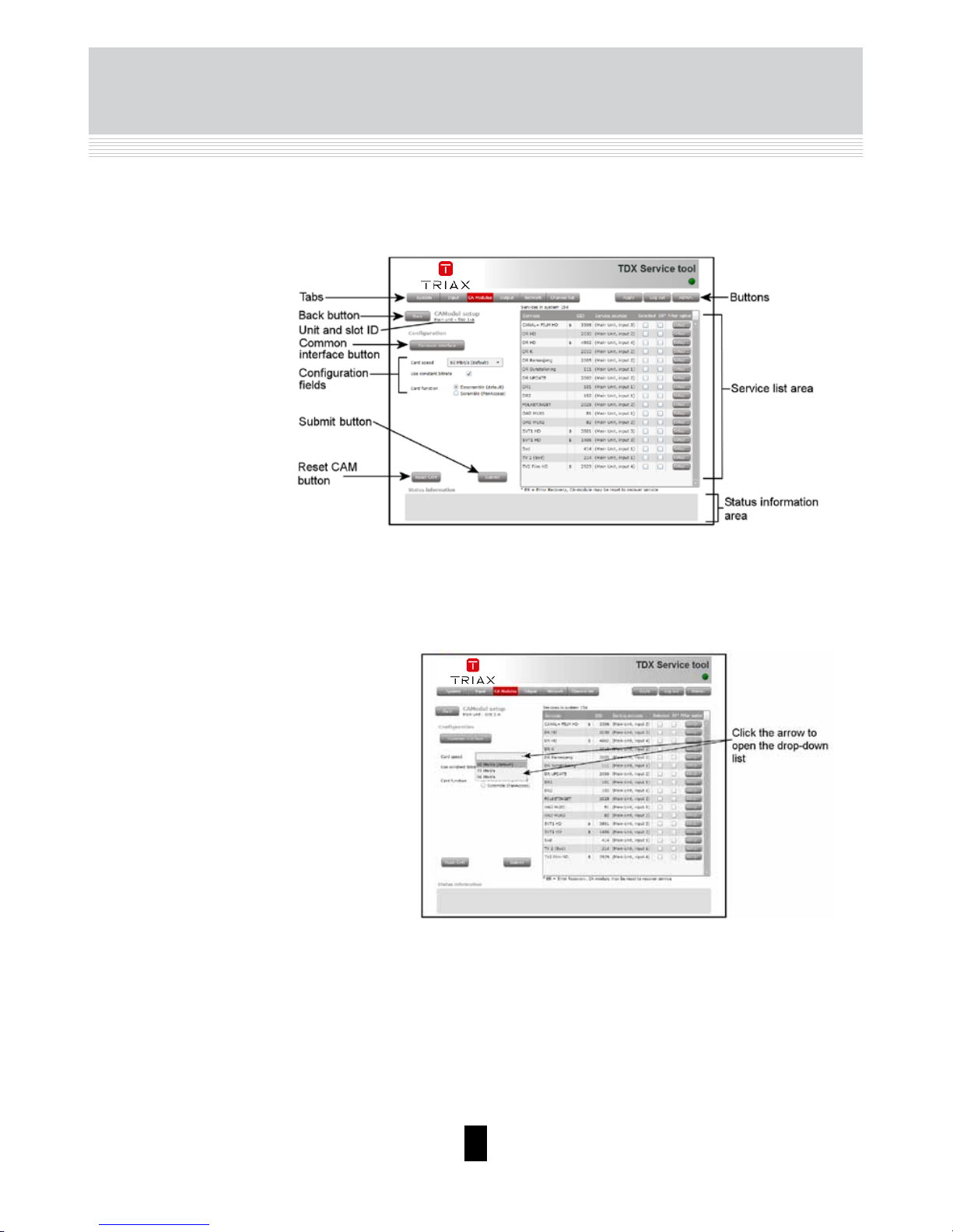
CA Modules configuration window
When you open the Configuration window for a CA module in a new configuration, only default values are displayed.
Card speed
Open the drop-down list with the card speeds if you want
a higher card speed than the default card speed.
Select the required card speed.
Use constant
bitrate
This check box is selected as default.
If you prefer a variable bitrate, instead of a bitrate where
null packets are used to keep the bitrate constant, click
the check box to deselect the use of constant bitrate.
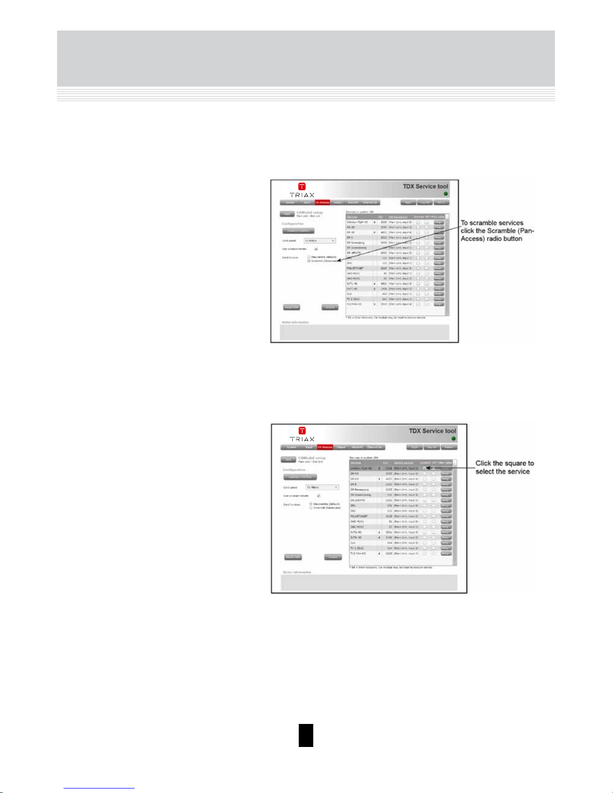
Card function
Here you decide whether you want the CA module to
descramble services that are scrambled or you want the
module to scramble services that are not scrambled .
Page 10
10
Rev. 01 - 2014 - E
TDX Service Tool
Select the service(s) that you want to descramble in the
Service list area by clicking the service(e).
Scrambled services are marked with a dollar sign - $.
The Descramble button is default.
Click the Scramble (PanAccess) button if you want to
scramble services using the PanAccess Scrambler.
If you select the ER checkbox of a service in the list area,
you enable automatic error recovery for the service.
Service list area
ER checkbox
By selecting the ER checbox you enable a constant monitoring of the signal transmission status through the CA
module.
The CA module is automatically reset if the signal transmission fails. When a CA module is reset, the signal transmission is interrupted for all the services associated with
that CA module.
Page 11

11
Rev. 01 - 2014 - E
TDX Service Tool
The ER checkbox should not be enabled for services
where signals are not transmitted on a 24-hour basis.
To change the Filter options for a service, click the Setup
button of the service in question to open the Filter options
window.
Filter option
By default all audio PIDs (Packet Identifier) associated
with the service are descrambled.
To descramble all PIDs that are not audio or video related,
click the Descramble non audio/video PIDs checkbox.
Page 12

12
Rev. 01 - 2014 - E
TDX Service Tool
Deselecting the Descramble all audio PIDs checkbox, displays a field with a drop-down list below the checkbox.
Open the drop-down list and select the the language of
the audio PID you want to descramble.
To descramble only selected audio PIDs you have to deselect the Descramble all audio PIDs checkbox.
An additional field with a language drop-down list is displayed every time you select a language. You can descramble as many audio PIDs as you need.
To remove a selection leave the field empty.
Page 13

13
Rev. 01 - 2014 - E
TDX Service Tool
If the language of the audio PID you want to descramble is not displayed in the list you can enter a three letter
string signifying the language you need.
Click OK to return to the Configuration window.
Please refer to the user guides of the CA modules and
smart cards you have inserted in the output modules for
further information.
Clicking the Common interface button gives you access
to information from the smart card inserted in the CA
module. The type of information provided by the smart
card depends on the card itself and its make.
Common
interface
If the CA module malfuntions, click the Reset CAM button
to reboot the TDX headend system.
Reset CAM
When a CA module is reset, the signal transmission is
interrupted for all the services associated with that CA
module.
A message window is displayed asking you to confirm
that you want to reset the CA module.
Page 14

14
Rev. 01 - 2014 - E
TDX Service Tool
Status information
To be implemented later.
Remember to click the Apply button in the upper righthand corner to save new settings in the configuration.
Submit
When you have made all the required selections, click the
Submit button to save this information in the headend
system and return to the CA Modules window.
The selected service(s) is now listed in the CA Modules
window next to the CA module.
Page 15

15
Rev. 01 - 2014 - E
TDX Service Tool
If you want to remove a CA module, click the Delete button of the module in
question in the CA Modules window.
A message window is displayed asking you to confirm that you want to remove the output module.
Delete CA module
If you want to display a history of the events related to the CA module, click
the Log button of the module in question to open the Event Log window.
Event log
Page 16

16
Rev. 01 - 2014 - E
TDX Service Tool
Output window
You have to configure the output modules individually.
Select a QAM output module and click the Setup button to display the Con-
figuration window of the module.
Click the Output tab in the TDX Service Tool to display the Output window.
The first time you display the Output window in a new configuration the
module list only displays the number and type of output modules that you
have inserted in the main and subunits.
Page 17

17
Rev. 01 - 2014 - E
Configuration of
output modules
The first time the Service Tool displays the Configuration window for an output module in a new configuration the fields in the window will display default
values and/or be empty, and the output module is disabled.
If you want to enable this module, click the Disabled
output checkbox.
Disabled output
Channel plan
To select another TV system, open the drop-down list
with the systems you can choose from.
Select the system you want to use.
TDX Service Tool
Page 18

18
Rev. 01 - 2014 - E
You can configure a QAM module either:
• by using the specifications of the channel plan
or
• by entering a frequency manually.
Using the channel plan denitions:
Open the drop-down list with the predefined channels
and select the channel you want to use.
When you have selected a channel the Frequency and
Channel spacing fields are automatically filled in.
Channel, Frequency and Channel
spacing
Enter a frequency manually:
Open the Channel drop-down list and select “Frequen-
cy” list.
Enter the desired frequency in KHz in the Frequency
field.
Open the drop-down list with the channel spacings and
select the channel spacing you want to use.
You can select services in two ways, either:
• by selecting services from the TDX-pool
or
• by selecting services from an input module you
select.
Select input
Services from the TDX-pool
Open the drop-down list and select “Services” from the
drop-down list.
Click the Services... button next to Select input field to
open the Select services window.
Note
When you have selected a channel using the
channel plan or entered a frequency manually,
then you have also set up the other three RF
channels on the module in question. You only
need to select services for each of the three
other RF channels, or disable one or more of
the three channels.
TDX Service Tool
Channel
Frequency
Channel spacing
Page 19

19
Rev. 01 - 2014 - E
TDX Service Tool
In the Select Services window you can select the service or services that you want to output.
Note
By clicking one of the underlined column
headlines you can sort the list into alphabetical or numerical order.
Click the checkbox to the right of the service(s) you
want.
By default each service listed in the Select services
window has an automatically assigned Service ID (SID)
which is displayed in the Output SID column.
Page 20

20
Rev. 01 - 2014 - E
If you want to give your selection of services a name,
enter the name in the Mux name field.
TDX Service Tool
The SID must be a number between 1 and 65535.
You can manually change the SID of the services you
have selected in the Output SID column.
The SID must to be unique inside a network with the
same Original Network ID (ONID) and Transport Stream
ID (TS-ID). All QAM output modules in your TDX headend system uses the same ONID but separate TS-IDs
for each output.
If you assign the same SID to services distributed via
the same output, the TDX system will check the SIDs
and display a warning that explains the problem.
Page 21

21
Rev. 01 - 2014 - E
Click OK to return to the Configuration window.
Note
The services you have selected will no longer
be available in the TDX-pool for other output
modules.
Services from input module
To select the services from a particular input module,
open the drop-down list of the Select input field and
select “Transparent” from the list.
TDX Service Tool
Click the Services... button to open the Select input
modules window.
Click the checkbox of the module you want to use.
If you want to give your selection of services a name,
enter the name in the Mux name field.
Click OK to return to the Configuration window.
Next you select or enter values in the other fields in the
Configuration window.
RF level correction
To select another RF level correction, open the dropdown list and select the level you want to use.
Symbol rate
Enter the desired symbol rate (from 3150 to 7200 kS) in
the Symbol rate field.
QAM mode
To select which QAM mode to use, open the dropdown list and select the QAM mode you want to use.
Transportstream
ID
By default each QAM output has an automatically assigned transport stream ID. It is possible to change the
ID.
Note
Each QAM output in your TDX headend system must have a unique transport steam ID.
Page 22

22
Rev. 01 - 2014 - E
TDX Service Tool
Payload monitor
The payload monitor above the status information area is a real time monitor,
which graphically indicates the amount of data that is currently being transmitted.
Changes in the configuration have to be submitted before the payload monitor can measure it.
The update frequency is approximately 5 seconds.
The Status information area also contains information related to the bandwidth monitor.
Manual SDT
version
By default this checkbox is deselected.
If it is necessary to control when a new SDT version
is sent, then select the checkbox and enter a version
number (0-31) in the field next to the checkbox.
It is recommended that you keep the default value.
Click the Submit
button to enter
your selections
Page 23

23
Rev. 01 - 2014 - E
When you have finished the configuration of the output, click the Submit button to enter the information into the headend system and return to the Output window.
Remember to click the Apply button in the upper right-hand corner to save
new settings in the configuration.
TDX Service Tool
Status information
SW revision
Displays the software version of the output module.
Status information about the output is placed at the bottom of the Configuration window.
Status
Informs you whether output is enabled or disabled.
Current payload
Informs you about the level of data that is currently being transmitted.
Max payload
Displays the maximum limit on how much data you can
transmit.
Note
The software version of the QAM module
must be identical with the software versions
installed on the other input/output modules as
well as the headend units.
Watch the status information to check that the output module.
Page 24

24
Rev. 01 - 2014 - E
When you return to the Output window the configuration of the output module is displayed in the module list.
Now you can configure the other outputs of the first QAM module and then
continue to configure the other output modules, following the procedure just
described.
TDX Service Tool
To remove an output module and the associated configuration you can use
the Delete button of the module in question in the Output window.
Click the Delete button of the QAM output module you want to remove.
A message window is displayed asking you to confirm that you want to re-
move the output module.
Delete output
modules
Until you have physically removed the output module from the headend unit
the module list will display four lines with the writing in red.
Page 25

25
Rev. 01 - 2014 - E
TDX Service Tool
If you want to display a history of the events related to the QAM output, click
the Log button of the output in question to open the Event Log window.
Event log
Page 26

26
Rev. 01 - 2014 - E
Network ID
Enter the required network ID in the Network ID field.
If it is an open network, the network ID has to follow
the “ETSI TR 101 211” guidelines. If it a closed network
you can determine the ID yourself.
Network IDs and and names are required for both both DVB-T and DVB-C.
Network name
Enter a network name in the Network name field. The
maximum number of characters you can enter in the
field is 255.
Network
window
Click the Network tab in the Service Tool to display the Network window.
The first time you display the Network window the fields in the window will
display default values and/or be empty. The service list area will display all
the digital services you have configured to output using the Output tab.
End-users need the network ID if they have to do a NIT (Network Information
Table) search when searching for services on their televisions or set-top boxes. Some set-top boxes may also need the original network ID in connection
with a NIT search.
Orig. network ID
Enter the required original network ID in the Orig. network ID field.
Set original ID
To change the default values of the original network ID,
click Set original ID checkbox to enable the Orig. network ID field.
TDX Service Tool
NIT standard
Select which standard you want to use, DVB or Nordig.
By default DVB is selected.
EIT information
The Event Information Table (EIT) drop-down list enables you to change the EIT settings for both DVB-T and
DVB-C.
Page 27

27
Rev. 01 - 2014 - E
Basically, the drop-down list gives you at choice between using a barker channel or using all outputs for
transmitting EIT informationl.
By using a barker channel all EIT information, i.e. actual
present/following and actual schedule EIT for all services, will be transferred from the individual outputs to
the barker channel thereby making more room/ payload
available to the transmission of services.
If you use a barker channel to carry the EIT
information you have to make sure that the
set-top boxes used by end-users are NorDig
compliant, i.e. they can read a Linkage Descriptor from a NIT.
Note
To use a barker channel for transmitting all EIT information, select “Barker channel” in the EIT drop-down list.
Below the EIT drop-down list, select the channel you
want to use as barker channel in the drop-down list.
TDX Service Tool
Page 28

28
Rev. 01 - 2014 - E
In the service list area you determine the numerical output order of the digital
services on the television or set-top box of the end-user.
Enable HD LCN
Select the Enable HD LCN checkbox if you want an HD
channel to take precedence over the same channel in
SD mode.
Note
You cannot give the same LCN number to
more services.
TDX Service Tool
If you prefer not to use a barker channel you have the following options:
Full Actual - Full Other All outputs will have all EIT information available, so
all actual present/following, actual schedule, other
present/following and other schedule EIT are sent
out with all muxes.
Full Actual - P/F Other All outputs will have actual present/following and
actual schedule EIT information, but only other present/following EIT information.
Full Actual - No Other All outputs will have actual present/following and
actual schedule EIT information, and no other EIT
information.
P/F Actual - P/F Other All outputs will have actual present/following EIT in-
formation and other present/following EIT information only.
P/F Actual - No Other All outputs will have actual present/following EIT
information.
No Actual - No Other No EIT information is output.
Manual transport
stream ID
Select the Manual transportstream ID if you want to enable the Transportstream ID field in the Configuration
windows for output modules.
Use static NIT
version
By default the Use static NIT version checkbox is deselected.
NIT version
Enter the desired number in the LCN number field to
the right of each service in the service list area.
Enable CAT tables
Enter the desired number in the LCN number field to
the right of each service in the service list area.
LCN number and
HD LCN Number
Enter LCN numbers for both the SD and HD channels
in the fields in the service list area.
Page 29

29
Rev. 01 - 2014 - E
TDX Service Tool
When you have entered the values you require you have to click the Submit
button to enter this information into the headend system.
Remember to click the Apply button in the upper right-hand corner to save
new settings.
When you have finished configuring all the output modules you have inserted
in the headend units the Channel list tab displays a list with all the channels
and services that you have selected.
Channel list
Page 30

30
Rev. 01 - 2014 - E
Apply
An important button when you change your configuration of the headend
system is the Apply button placed in the upper right-hand corner of the TDX
Service Tool window.
Save configuration
Whenever you have made changes in your configuration,
“Apply” on the Apply button turns red to tell you that you
have unsaved changes that need to be saved.
Click the Apply button to save the changes. When changes have been saved the “Apply” text turns white again.
TDX Service Tool
Page 31

31
Rev. 01 - 2014 - E
Your notes
Page 32

DECLARATION OF CONFORMITY
TRIAX confirms that the product conforms to relevant EEC harmonised standards and consequently can carry the CE-mark.
Relevant harmonised standards:
DE/EN 60728-2 2010, DS/EN 60728-11 2010 and DS/EN 50083-2 2006
This document is only valid with the signature of the person responsible for CE-marking by Triax
Date: October 2012 Signature:
Dear Customer,
Should you require technical assistance in the event that your
expert dealer is unable to help you, please contact us at:
Triax A/S
Bjørnkærvej 3
8783 Hornsyld
Denmark
Manufacturer
Copyright © 2016 TRIAX. All rights reserved. The TRIAX Logo and TRIAX, TRIAX Multimedia
are registered trademarks or trademarks of the TRIAX Company or its afliates.
All specications in this guide are subject to change without further notice.
TRIAX A/S | Bjørnkærvej 3 | DK-8783 Hornsyld | Denmark
triax.com/support
 Loading...