

Page 1
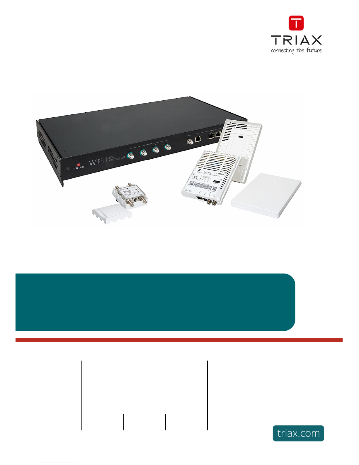
User Manual
Controller / Endpoint / RP filter
Ethernet over COAX
Article Article no.
EoC
Ethernet over COAX
Controller / Endpoint / RP filter
383101
383103
383200
383900
Version 1.2 Date 09/2018 EN
Page 2

Ethernet over COAX
1
EN
Safety Instructions ....................................................................................................................................................... 2
1.
The EoC solution – unmanaged or managed via In Touch ........................................................................ 3
Overview of components......................................................................................................................4
EoC Controller .......................................................................................................................................4
EoC Endpoint.........................................................................................................................................5
EoC Return path (RP) filter ...................................................................................................................5
2.
Standard configuration groups .................................................................................................................. 6
Initial Setup ...........................................................................................................................................6
Private only ...........................................................................................................................................6
Guest only .............................................................................................................................................6
Guest and Private .................................................................................................................................6
3.
How to connect standard configuration groups ........................................................................................ 7
Private network .....................................................................................................................................7
Guest network .......................................................................................................................................7
IP TV network........................................................................................................................................7
4.
Controller setup .......................................................................................................................................... 7
Operation ..............................................................................................................................................7
Ports ......................................................................................................................................................7
Mounting ...............................................................................................................................................7
5.
Endpoint setup ............................................................................................................................................ 8
Operation ..............................................................................................................................................8
LEDs on endpoint ..................................................................................................................................8
Reset .....................................................................................................................................................8
Mounting ...............................................................................................................................................8
6.
Controller interface ..................................................................................................................................... 9
Configuration wizard ............................................................................................................................9
Status ....................................................................................................................................................9
Network .............................................................................................................................................. 10
System ............................................................................................................................................... 12
Performance ...................................................................................................................................... 13
7.
Endpoint interface .................................................................................................................................... 13
Scan the QR code............................................................................................................................... 13
8.
Support...................................................................................................................................................... 13
Page 3
Ethernet over COAX
EN
2
Safety Instructions
To prevent fire, short circuit or shock hazard
Do not expose the unit to rain or moisture.
Install the unit in a dry location without infiltration or condensation of water.
Do not expose it to dripping or splashing..
If any liquid should accidentally fall into the cabinet, disconnect the power plug.
To avoid any risk of overheating
Install the unit in a well aired location and keep a minimum distance around the apparatus for
sufficient ventilation
Do not place anything on the unit that might cover the ventilation holes.
Do not install the product in a dusty place
Use the apparatus only in moderate climates (not in tropical climates)
Respect the minimum and maximum temperature specifications
To avoid any risk of electrical shocks
Attach protective earth connection to apparatus
The mains plug shall remain readily operable
Pull out power plug when making connections of cables
To avoid electrical shock, do not open the housing.
To avoid interferences with LTE services in Europe
Do not select a channel higher than UHF 48 in countries with LTE II / 700 operation
Do not select a channel higher than UHF 60 in countries with LTE I / 800 operation
Use coaxial cables with screening effectiveness of >85dB (Class A) at least or >95dB (Class A+)
WEEE disposal
This product may not be not be disposed of with general household waste
Follow applicable national legislation when disposing of this product
ATTENTION
Failure to comply
with the specified precautionary measures may cause serious injury to persons
or damage to property. The installation and commissioning may only be performed by suitably
qualified persons, technicians or installers in compliance with safety regulations.
Damage due to improper installation and commissioning, defective connectors on cables or any
other incorrect handling will void the warranty.
CAUTION: The safety requirements are according to EN 60728-11 and must be observed.
Disconnect mains power before working on electrical systems.
Any additional electrical wiring requirements should always be installed by a suitably
qualified person(s).
Installation or service work should NEVER be undertaken during electrical / thunderstorms.
Page 4
Ethernet over COAX
3
EN
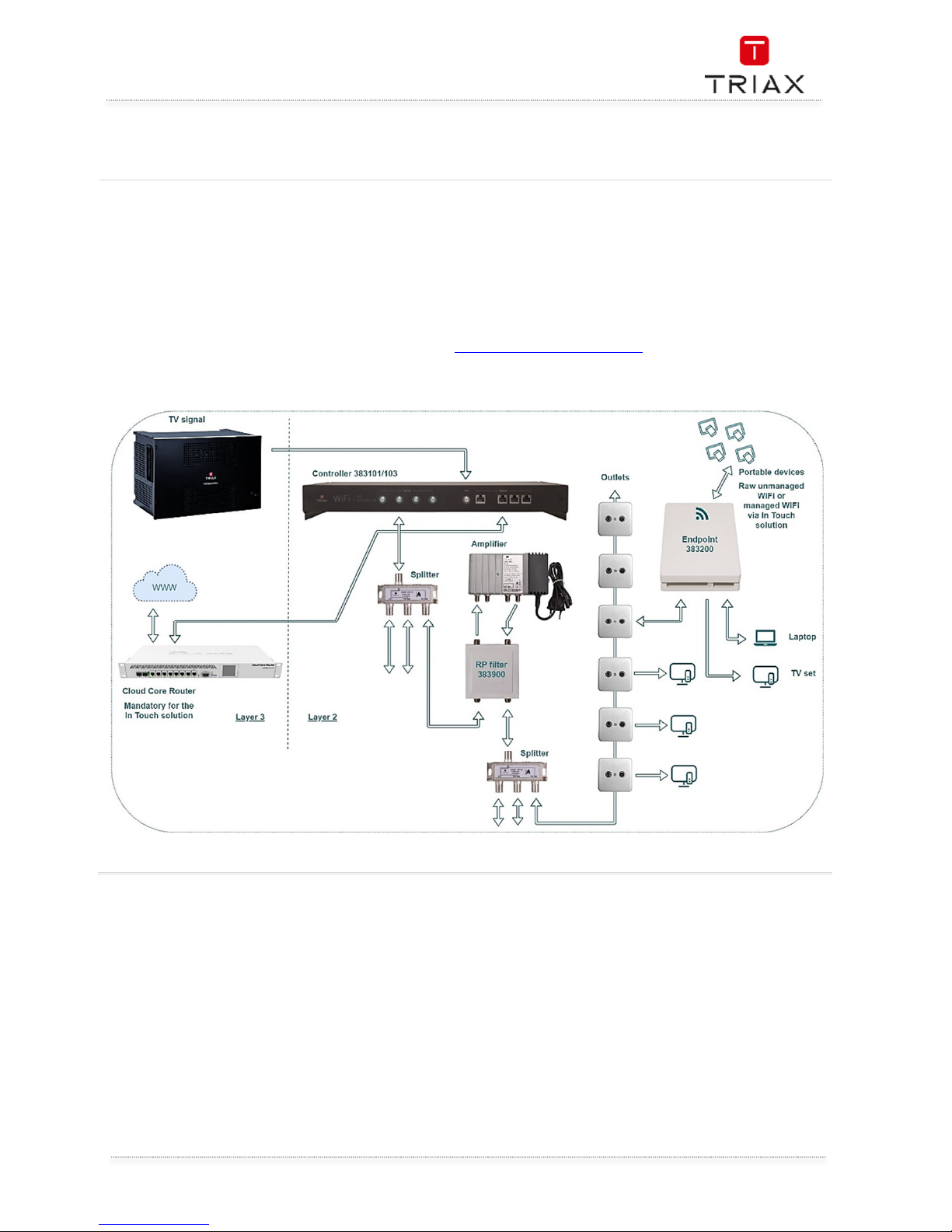
1. The EoC solution – unmanaged or managed via In Touch
Ethernet over Coax (EoC) allows the configuration of ethernet transport layer 2 traffic via a coax network in
coexistence with TV signals.
EoC is a straightforward system, well suited for retro-fitting into an existing coax installation with no or minor
modifications. With this solution the user is given raw WiFi.
EoC can also be used in combination with a TRIAX In Touch managed solution to add layer 3 functionality.
This gives the user a managed In Touch solution where the WiFi bandwidth per device can be controlled; as well
as providing a range of value added services.
For In Touch solutions, see separate information here: http://www.triax.com/intouch
Page 5
Ethernet over COAX
EN
4
Overview of components
To install the EoC controller and endpoints it is recommended to use the following process:
Start with the controller
Use the controller interface to
configure the system as needed
or use the standard configuration
(see paragraph “8.
Controller interface”)
Mount the controller
Attach cabling to controller
Then install endpoints
Mount the backplate of the endpoint
Attach cabling to endpoint
Click in the inner box of the endpoint and
wait for the LEDs to show that the
endpoint is up and running
Log onto the setup WiFi
(TriaxSetup_xxxx)
Scan the QR code on the endpoint, to get
a link to the endpoint installation page
and open this in a browser
Choose the configuration group needed
for the endpoint and fill out the text fields
Attach the lid of the endpoint and you
are done.
Using this process will allow for easier configuration of the endpoints, as the specific configuration groups
have already been set up and there is no need for individual setup of the endpoints, just choose the correct
configuration group and you are done.
EoC Controller
Page 6

Ethernet over COAX
5
EN
EoC Endpoint
EoC Return path (RP) filter
Page 7

Ethernet over COAX
EN
6
2. Standard configuration groups
The EoC controller and the endpoint comes with standard configuration groups. These can be used if you do
not need any further WiFi SSIDs or configuration of ethernet ports.
The standard configuration can be used in any
network where there is a need for
1. A private network, where clients must be
able to communicate with each other.
This could be printing from a PC to a
network printer or a PC needs to get files
from a local server etc.
2. A public guest network, where clients
cannot see each other (client isolation
active). This allows for a public WiFi,
where guests cannot access others
devices in the EoC system.
3.
IP TV distribution
The standard configuration on the controller is as
follows
Ethernet port 1: Fixed for management
port (VLAN 10)
Ethernet port 2: Private network (VLAN
50)
Ethernet port 3: Guest network (VLAN
100)
Ethernet port 4 : IP TV (VLAN 80)
All inbound traffic on the ethernet ports are tagged with the appropriate VLAN.
The controller is set up with the four standard configuration groups (Setup, Private, Guest, Guest & Private) as
a default.
A configuration group is a specific configuration used for the endpoints. A configuration group defines how
an endpoint is set up with WiFi, VLANs, port tagging.
This allows for simple configuration of an endpoint by assigning it to a group instead of applying all settings
individually.
The four configuration groups are described below
Initial Setup
This is a group that is used only for initial setup of the
endpoint.
All new endpoints will by default be configured with
this group.
An endpoint in this group broadcasts the
TriaxSetup_xxxx WiFi SSID, which allows you to
connect to the controller to configure an endpoint.
It sets the endpoint up as follows:
VLAN 10 on etherned port (Use to access
the controller interface
SSID: TriaxSetup_xxxx (VLAN 10)
Private only
This is a group for a private VLAN. It sets up the
endpoint as follows:
VLAN 80 on ethernet port (Mainly used
for IP TV – but basically a private
VLAN)
SSID: Private (VLAN 50)
Guest only
This is a group for a public guest network. It sets up
the endpoint as follows:
VLAN 80 on ethernet port (Mainly used
for IP TV – but basically a private VLAN)
SSID: Guest (VLAN 100, with client
isolation)
Guest and Private
This is used for an endpoint which serves both
private and public WiFi. It sets up the endpoint as
follows:
VLAN 80 on ethernet port (Mainly used
for IP TV – but basically a private VLAN)
SSID: Private (VLAN 50)
SSID: Guest (VLAN 100, with client
isolation)
Page 8

Ethernet over COAX
7
EN
3. How to connect standard configuration groups
Private network
Connect a CAT cable from your router/modem to
port 2 on the controller.
This will allow any endpoint with the “Private only” or
“Guest & Private” configuration to send out a WiFi
(SSID Private) with Internet.
On this network, devices can communicate with each
other.
This Private network uses VLAN 50.
Guest network
Connect a CAT cable from your router/modem to
port 3 on the controller.
This will allow any endpoint with the “Guest only” or
“Guest & Private” configuration to send out a WiFi
(SSID Guest) with Internet.
On this network, it is not possible for devices to see
each other or share data, as client isolation is
activated.
This Guest network uses VLAN 100.
IP TV network
Connect IP TV signal to ethernet port 4 on the controller. This will then be sent out on the ethernet port of any
endpoint with the “Guest only”, “Private only” or “Guest & Private” configuration. This IP TV network uses
VLAN 80.
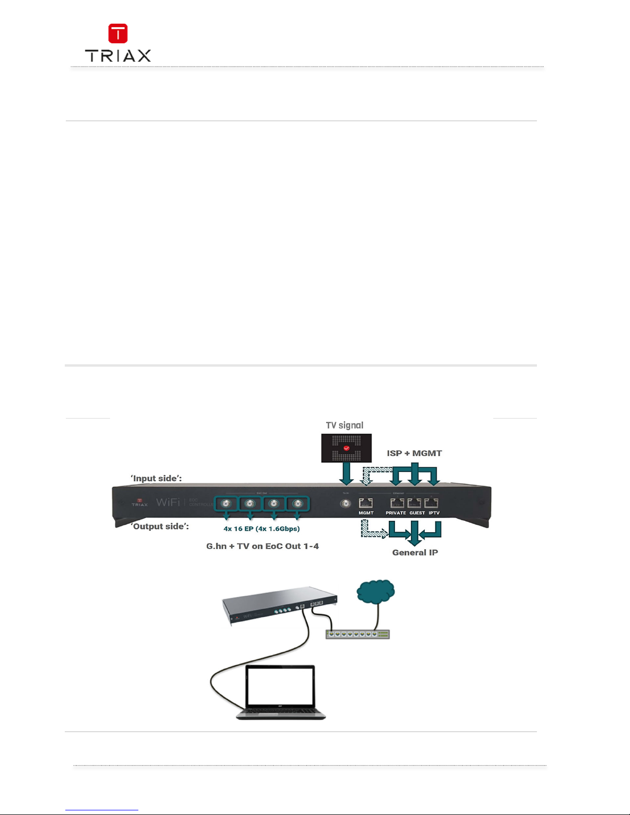
4. Controller setup
Operation
The controller acts as a layer 2 switch with a built in media converter.
Therefore, it is intended that a router is connected to the controller ethernet ports, facilitating IP address
management (DHCP) and providing Internet access.
Ports
The ethernet ports are described in the paragraph “2. Using the standard configuration”.
The TV in port allows for TV signals in the 300-862 MHz range.
The EoC out ports communicate using network (data) signals on 2-200 MHz and send out TV signals on 300862 MHz. The TV and network (data) signals will be split again at the endpoint.
Each EoC out port can support up to 16 endpoints. If more than 16 endpoints are connected to a single EoC
out port, then any endpoints above the 16th connected will not function.
Mounting
Controller can be mounted and stacked in Rack (19HE), or wall mounted in any direction needed.
Page 9

Ethernet over COAX
EN
8
5. Endpoint setup
Operation
Each endpoint has two RF ports, EoC + TV and TV out.
The EoC + TV port communicates using network (data) signals on 2-200 MHz and receives TV signals on
300-862 MHz.
The endpoint splits the signals into network data, accessible through ethernet and WiFi, and TV out.
LEDs on endpoint
Signal
No light: No network data connection to
the controller.
Flashing light: Communicating with the
controller.
Solid light: Network data connection to
controller established.
Colour Green: Good working connection.
Colour Orange/Yellow: Connection issues
(poor signal or authentication issues ).
Colour Red: Connection error (very poor
signal).
Status
No light: Endpoint is not powered on
(main CPU not running).
Flashing light:
o Slow (1s frequency):
Starting up or rebooting.
o Fast (200ms frequency):
Configuration
synchronization or FW
updating.
Solid light: Endpoint is powered on.
WiFi
No light: WiFi is turned off.
Flashing light: Indicates an error state.
Solid light: WiFi is turned on.
Reset
A paper clips or similar can be used to press the reset button on the endpoint.
This will trigger a reboot and remove the configuration data on the endpoint.
After start up the endpoint will automatically download the configuration from the controller, corresponding
to the group the endpoint is assigned to.
Mounting
For optimal WiFi coverage and for optimal cooling, always mount the Endpoint vertically on a wall as shown.
Page 10

Ethernet over COAX
9
EN
6. Controller interface
It is possible to access the web interface by connecting a PC via ethernet to port 1 on the controller. Open a
browser and type in http://setup.eoc and type in the admin username and password. By default this is
admin/admin, but is usually changed through the configuration wizard.
Configuration wizard
When accessing the controller interface for the first time, the configuration wizard welcome page will be
shown. In case this is not automatically shown, it can be accessed at: http://setup.eoc/config_wizard
At the configuration wizard welcome page you have the possibility to choose either:
Configuration wizard: this will take you through the most common configuration options:
Administrator account settings
Checking internet connection
Firmware update
Date & time settings
Restore/import configuration from backup
G.hn filters
(filter settings, filter setup ?)
WiFi settings
Configurations groups
Configure manually: skip the configuration wizard
Status
The system status page gives you an overview of the controller and the endpoints connected to the
controller.
The WiFi Clients status will show you which clients (if any) are connected to the WiFi of the endpoints.
Ethernet clients status will show you which clients (if any) are connected to an ethernet port on the
endpoints.
NOTE
After changing any settings, you must press the Save & Apply button, before the specific settings
takes effect on the endpoint or controller.
In the top right corner of the controller interface you will see a red disk if there are settings that have
been changed but not applied yet. If the disk is green all settings have been saved and applied.
Changes done in the configuration wizard are automatically saved and applied, after clicking “Finish”
on the last page
NOTE
After completion of the configuration; the wizard will not automatically be started
again.
Page 11

Ethernet over COAX
EN
10
Network
Change of settings of the network infrastructure, including the coax data connection.
Management settings
Apart from the default controller management interface on ethernet port 1 (setup VLAN 10), it is possible
here to allow management access through an additional VLAN (ethernet port) of your choice.
Furthermore, you can configure IPv4 settings used for management.
VLAN settings
This sub-page allows you to create any VLANs you need, which then can be configured on either WiFi SSIDs
or ethernet ports.
The default VLANs can be changed or they can be deleted, if you prefer to create your own. The Setup VLAN
cannot be deleted.
You can add a new VLAN by simply clicking ‘Add’. Then type in the name you want and the VLAN number you
wish to use (any number in the range 2-4095 can be used. VLAN 0 and 1 are reserved).
Checking the ‘Client isolation‘ will prevent any network traffic to flow between clients connected to this VLAN
in the EoC system. In such a VLAN the clients cannot see each other or interact unless this is done through
an external (Internet) server. For the client isolation to work correctly, please ensure that any network
infrastructure (routers and switches) connected to a client isolated VLAN of the EoC system also has a client
isolation feature.
WiFi settings
For WiFi radio settings see the “Endpoints settings” paragraph.
The WiFi settings allows to create multiple SSIDs to use on the endpoints.
The default SSIDs can be changed or deleted as needed, however the TriaxSetup_xxxx SSID cannot be
deleted.
The default SSIDs and their corresponding keys (passphrases) for authentication are listed below:
TriaxSetup_xxxx “SetupPasswordxxxx” (where “xxxx” are the last 4 characters of the controller
management interface MAC address)
Guest: “guestpassphrase”
Private: “privatepassphrase”
You can add a new SSID by simply clicking ‘Add new’. This allows you to create a new SSID with 2.4 and/or
5.0 GHz radios and the VLAN you prefer to use and the encryption needed.
If you choose to use encryption, you will need to enter a key (passphrase) for this SSID.
Ethernet settings
These settings allows you to configure the specific ethernet ports.
The controller port 1 settings cannot be changed, as this is by default a management port for the setup VLAN
(10).
The other controller ethernet ports can be configured as needed.
The controller ethernet is configured individually per port, and the endpoint ethernet port settings are
configured as a table of rules.
Each rule can be assigned to an endpoint configuration group (see “Group settings”).
This means that all endpoints within a certain configuration group will all have the same ethernet rule
settings.
NOTE
If you are using more than one VLAN for Internet, any router in front of the controller is required to
have either different subnets configured for each VLAN and/or VLAN separation for the client
isolation to work properly.
Page 12

Ethernet over COAX
11
EN
Network
Access VLAN
All inbound traffic that does not already
have a VLAN tag will be tagged with the
access VLAN.
Trunk VLAN
All: Traffic tagged with any VLAN created
in “VLAN settings” is allowed through the
port.
None: Traffic tagged with any VLAN is
blocked/dropped.
Only: Traffic tagged with the chosen
VLANs is allowed through the port.
DHCP filter
This setting is only available for endpoint rules. The filter will prevent rogue DHCP servers (routers) connected
to the endpoint ethernet ports to assign IP addresses to clients in the network.
G.hn settings - Multicast configuration and IGMP range
In case it is desired to use multicast traffic and IGMP/MLD capabilities, e.g. for IP TV, the parameters should
be configured accordingly. For a generic multicast setup using IGMP, the configuration should be:
Multicast Snooping type: IGMP
Broadcast IGMP/MLD reports allowed: Yes
Filter unknown multicast traffic: Yes
IGMP Multicast ranges configuration: the IP addresses used for multicast must be within the
range
If Multicast traffic and IGMP/MLD capabilities are not required, it is recommended for optimal performance
to configure the following:
Broadcast IGMP/MLD reports allowed: No
Filter unknown Multicast traffic: No
Notch filters
It is possible to change the frequency range used by the network data traffic.
The network data traffic will use the 2-200 MHz frequency range by default.
Adding a Notch filter and enabling it will remove the chosen range. Removing a range will allow for other
traffic to utilize this range, but also lower the total bandwidth available for network data.
By default there is a predefined disabled FM radio notch filter in the configuration. This can be enabled in
case it is desired to use the coax network for FM radio and network data signals at the same time.
All notch filters are configured using:
Start freq (kHz): This is the frequency you wish your filter to start. Please note this is in kHz and not MHz.
Stop freq (kHz): This is the frequency you wish your filter to stop. Please note this is in kHz and not MHz.
Depth: This is the attenuation of the network data signal. To completely avoid using the frequency range
choose 100 dB (complete carrier removal). All other values will only attenuate the network data signal, and it
will still be used for communication in the chosen frequency range.
Group settings
A group setting is used to quickly assign a full configuration to an endpoint. A group setting is comprised of
one or more WiFi SSIDs (if needed) and an ethernet rule to apply for the ethernet port on the endpoint.
The default groups can be changed or deleted as needed.
You can add a new Group by clicking the ‘Add’ button. Type in the name of your group, add as many WiFi
SSIDs as you need and choose an ethernet rule for the ethernet port.
Page 13

Ethernet over COAX
EN
12
Network
Endpoint settings
It is possible to see all endpoints configured on the controller.
Endpoints which has just been connected will get the configuration from the Setup group, which means that
they will broadcast a WiFi SSID called TriaxSetup_xxxx and the ethernet port can be used to connect to the
controller interface.
For each endpoint it is possible to configure the 2.4 GHz / 5 GHz radio settings individually. This includes
adjusting the transmit (Tx) power, WiFi channel and the channel width as well as what WiFi modes are
allowed.
System
Here system settings not related to network settings can be changed.
Date & time settings
You can choose to use the time servers already configured or add a new timeserver, if you wish to use a
custom.
Account settings
This is where you can change the login for the controller interface.
Backup & restore
You can export the current configuration as a backup file. Backup files can also be imported, which will
overwrite the current settings of the controller, and replace them with the settngs in the backup file.
Import will overwrite the current settings of the controller and replace them with the settings in the backup
file.
When setting up multiple controllers in multiple locations, you could duplicate the settings, by setting up one
controller, exporting a backup and then import that backup to other controllers.
You also have the possility to reset the controller to the factory default configuration.
Remember that this not only affects the controller as any connected endpoints will now get the default
configuration as well.
Firmware update
This allows you to update the firmware used by the controller and endpoints. Any firmware applied to the
controller will transfer to the endpoints.
Logs & reports
Here you can export logs of what has been happening in the system or export an equipment file showing all
equipment connected to the controller (including the controller).
Reboot
Here you can manually reboot the controller. No changes will be made to configuration, the controller will
shut down and boot back up.
Page 14

Ethernet over COAX
13
EN
Performance
In the performance page, you can choose an endpoint and start a TCP traffic test. The results are listed in a
table, including up and download speeds.
7. Endpoint interface
While connected to eihter the “TriaxSetup_xxxx” WiFi SSID or to the controller management interface on
ethernet port 1, you can scan the setup QR code on an endpoint. This will provide a link to access the
endpoint installation page, hosted by the controller, for that specific endpoint. You need to enter the controller
admin password to continue. (see paragraph 8. Controller interface)
The endpoint installation page can alternatively be accessed at
http://setup.eoc/endpoint/AA:BB:CC:DD:EE:FF where “AA:BB:CC:DD:EE:FF” must be substituted with the
endpoint MAC address found on the front label.
It is then possible to choose a configuration group for this specific endpoint, give it a name for reference, and
optionally type in a location or description.
Scan the QR code
While connected to the “TriaxSetup_xxxx” WiFi SSID, you can scan the setup QR code on the endpoint. This
will provide a link to access the controller setup page for that specific endpoint.
You need to enter the controller admin password to continue.
It is then possible to choose a configuration group for this specific endpoint and write in a name and/or
location.
8. Support
To get support, please access our support sites at http://www.triax.com/b2buserregister
You have to be a registered user in order to log in.
ATTENTION
Be careful how to interpret the results! The test can’t be used to validate the data rate throughput
experienced by clients on WiFi or ethernet, as the data rate throughput available for the test is limited.
Furthermore, any network data traffic (from other sources) can influence the results, as the coax
medium and internal switching capabilities of the system are shared among devices.
In case it is desired to validate the data rate throughput as experienced by clients, please use
appropriate test quipment.
NOTE
Because the endpoint installation page is hosted by the controller; it can’t be accessed if the endpoint
is not connected to the controller, even though the TriaxSetup_xxxx WiFi SSID’s is available
Page 15

Notes-Notizen-Notes-Notas-Notater
Page 16

triax.com
triax.dk - triax.se - triax-gmbh.de - triax.fr -
triaxmultimedia.es - triax.uk
triax.at – triax.hu
Information and manuals
:
Information og brugervejledninger:
Information och manualer:
Information und Bedienungsanleitungen:
Informations et modes d’emploi:
Información y manuales:
Lisätietoja ja oppaita:
információk és útmutatók:
Copyright © 2018 TRIAX. All rights reserved.
The TRIAX Logo and TRIAX Multimedia are registered trademark(s) of the
TRIAX Company or its affiliates.
TRIAX A/S | Bjørnkærvej 3 | 8783 Hornsyld | Denmark
Subject to change without notice
Änderungen vorbehalten
Peut être sujet à modification sans préavis
 Loading...