

Triax CGMM 480, 325019, CGMS 480, 325018 Assembly Manual

AssemblyInstruction
CGMM480/CGMS480
Model Itemno.
CGMM 480
CGMS 480
Version 10 Date 07/2016 EN
325018
325019

Contents
1 Safety regulations ..............................................................................................3
2 General information ..........................................................................................3
2.1 Scope of delivery ............................................................................... 3
2.2 Meaning of the symbols used ............................................................... 4
2.3 Technical data.................................................................................... 4
2.4 Description ....................................................................................... 5
3 Installation ........................................................................................................6
3.1 Installing the modulator module ............................................................ 6
3.2 Connecting the modulator module ........................................................ 7
4 The control panel at a glance .............................................................................8
4.1 Menu items ........................................................................................ 8
4.2 Functions of the control panel buttons .................................................... 8
5 Programming ....................................................................................................9
5.1 Preparation........................................................................................ 9
5.2 Programming procedure .................................................................... 10
5.3 Programming the modulator module ................................................... 11
Selecting the module / channel strip ................................................... 12
Switching on the modulator ............................................................... 12
Selecting channel / frequency setting.................................................. 13
Setting the output channel .................................................................. 13
Setting the fine tuning ....................................................................... 13
Setting the output frequency ............................................................... 14
Setting the output level ...................................................................... 14
Selecting the audio signal ................................................................ 15
Storing data .................................................................................... 15
6 Final procedures .............................................................................................. 16
7 Channel and frequency tables ..........................................................................17
- 2 - CGMM 480 / CGMS 480
1 safety regulations
• The standards IEC/EN/DIN EN 50083 resp. IEC/EN/DIN EN 60728 must
be observed.
• Do not perform installation and service work during thunderstorms.
• Assembly, installation and servicing should be carried out by authorised
electricians.
• Switch off the operating voltage of the system before beginning with assembly or service work.
• Avoid short circuits!
• Observe the relevant standards, regulations and guidelines on the installation and operation of antenna systems.
• To ensure electromagnetic compatibility, make sure all connections are tight
and the covers are screwed on securely.
• No liability is accepted for damage caused by faulty connections or inappropriate handling of the device.
Check the head-end station CSE 2800 according to the safety instructions
listed in their assembly instruction.
Take precautions to prevent static discharge when working on the device!
Electronic devices should never be disposed of in the household rubbish. In
accordance with directive 2002/96/EC of the European Parliament and the
European Council from January 27, 2003 which addresses old electronic and
electrical devices, such devices must be disposed of at a designated collection
facility. At the end of its service life, please take your device to one of these
public collection facilities for proper disposal.
2 general information
2.1 sCo pe of d e livery
1 CGMM 480 OIRT, CGMM 480 or CGMS 480 module
1 RF cable with F plugs
1 CD (assembly instructions)
1 Brief Assembly Instructions
- 3 - CGMM 480 / CGMS 480
2.2 mea ning of t he sy mbols u s ed
Important note
—> General note
–
–
/
/
Optional use of the buttons
• Performing works
2.3 teChniC al data
The requirements of the following EU directives are met:
2011/65/EU, 2014/30/EU, 2014/35/EU
The product fulfils the guidelines and standards for CE labelling.
Unless otherwise noted all values are specified as "typical".
RF outputs Modulators A / B / C / D:
Channels:
CGMM 480 / CGMS 480 ...................... PAL B/G;
C 02…C 69, S 03…S 41
CGMM 480 OIRT................. PAL D/K; R 01…R 12; s 01…s 38, C 21…C 69
Frequency range:
CGMM 480 / CGMS 480 ............................... 48.25 MHz…855.25 MHz
CGMM 480 OIRT.............................................49.75 MHz…855.25 MHz
Output level: .............................................................................85 dBµV
Output impedance: ............................................................75 Ω, nominal
Video:
Signal-to-noise ratio:.......................................................................55 dB
Frequency response: ........................................................ 20 Hz…5 MHz
Audio:
Frequency response: ........................................................40 Hz…15 kHz
Connections:
RF output: .............................................................................. 1 F socket
Connection strip (20-pin): ........................
AV input: .......................................................................
- 4 - CGMM 480 / CGMS 480
Supply voltages and control circuits
26-pin
pin socket

2.4 des C ription
The modulator modules contain four modulators, which convert existing CVBS
and audio signals into CCIR PAL B/G signals in the C 02 … C 69 channel
range (CGMM 480 / CGMS 480) or OIRT PAL-D/K signals in the channel
range R 01 … C 69 (CGMM 480 OIRT) via the AV interface.
The modulators are labelled (analogue to the channel strips) as "A", "B", "C"
and "D", and can be individually programmed. Four LEDs indicate if the respective modulator is switched on (LED illuminates) or off.
The audio and video signals being fed in through the 26-pin socket of the mod-
ulator module are modulated onto the carrier frequencies (channels) which
have been selected. The RF output signals are sent through the RF output on
the modulator module to the output collector. The levels of the RF output signals
are adjustable by software.
When the head-end station is switched on, the two-line LC display shows the
"SETUP" menu and the software version of the control unit. The head-end station total output level can be adjusted in this menu.
If the modulator modules are not detected by the head-end station you can up-
date the head-end station’s operating software via the head-end station’s 9-pin
D-Sub socket, using a PC or notebook and the "BE-Flash" software. To operate
the
digital module
the software version of the control unit (head-end station)
must be "V 10" or higher. You can find the current operating software for the
head-end station, the software "BE-Flash"
and the current assembly instructions
on the website "www.triax.com".
The modulator module is designed exclusively for use in the CSE 2800 head-
end station.
- 5 - CGMM 480 / CGMS 480
3 installation
– Ensure the head-end station is mounted so it will not be able to vibrate.
Avoid, for example, mounting the head-end station onto a lift shaft or any
other wall or floor construction that vibrates in a similar way.
– Before installing or changing a module, switch off the head-end station or
unplug the power cable from the mains power socket.
Take measures to protect against ESD!
• Open the housing of the head-end station in accordance with the assembly
instructions for the CSE 2800.
3.1 installi ng the m odulat o r modu le
– Always position modules which belong together next to each other. The
modulator module must be installed to the right of the digital module or an
add-on module.
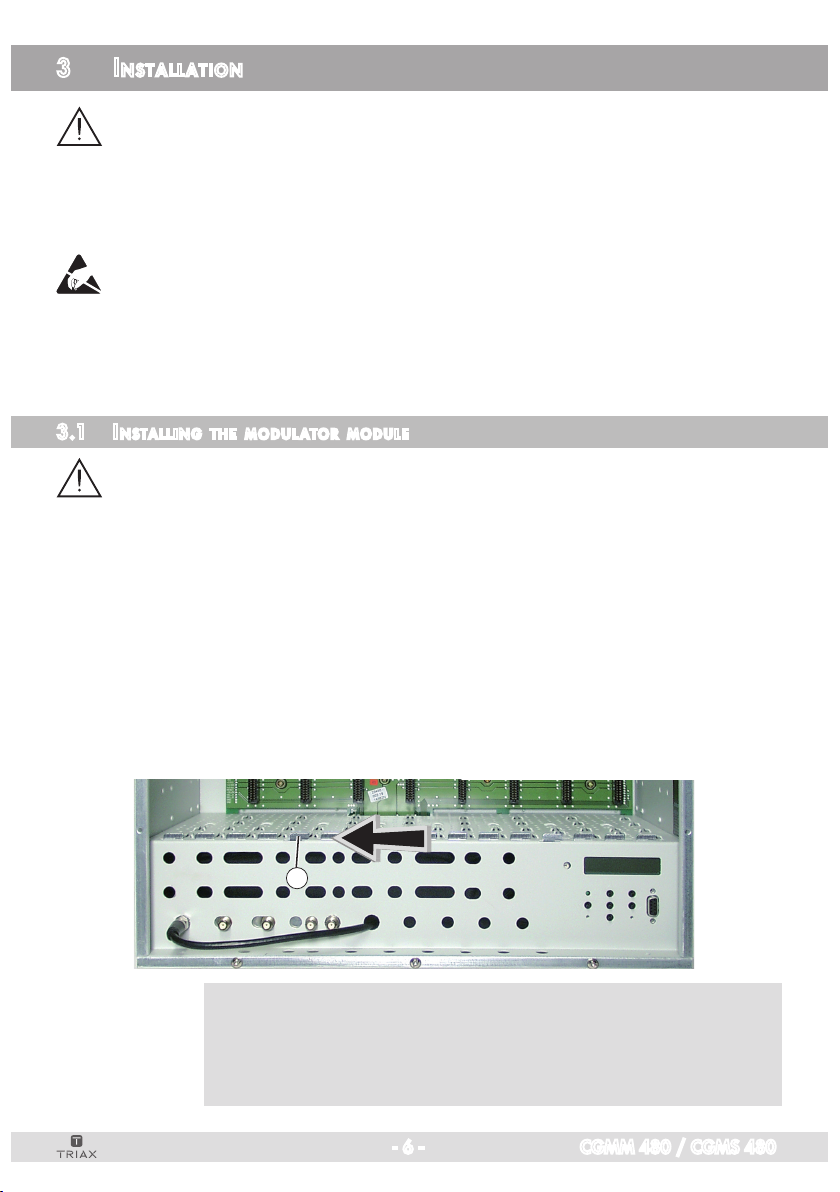
– When installing a module, make sure that it is inserted in the long numbered
grooves in front of the contact strip on the board at the rear wall of the housing.
The shorter, not numbered grooves without contact strip on the board at the
rear wall of the housing are for add-on modules only.
• Open the housing of the head-end station in accordance with the assembly
instructions for the CSE 2800.
• Open the locking device 1 in the direction of the arrow.
1
—> Slots 1 (digital module) and 2 (modulator module) are shown in the
following figure. The open slot in between (without a contact strip
on the board at the rear wall of the housing) is intended for an addon module.
- 6 - CGMM 480 / CGMS 480
 Loading...