

Page 1
User’s
Information
Manual
&
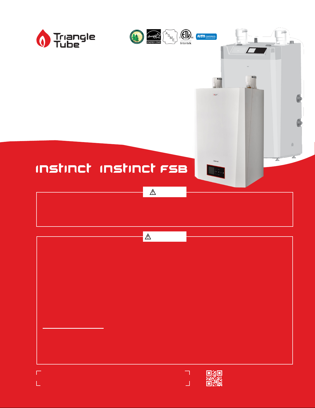
SOLO 110-155- 199 & COMBI 155-199
- Customer must register unit within thirty (30)
days of installation in order to gain warranty
coverage. See Warranty Card for details.
NOTICE
- Leave all documentation received with
appliance with the owner for future
reference.
• To maintain the safety & longevity of
your appliance, read and follow the
maintenance schedule information
throughout this manual.
• If the information in this manual
is not followed exactly, a fire or
explosion may result causing
substantial property damage,
serious injury, or death.
WARNING
FOR YOUR SAFETY
• Do not store or use gasoline or
other flammable vapors and liquids
in the vicinity of this or any other
appliance.
226977 A02 - Oct 2021
2019-17 Instinct WHB
& FSB User
Information Manual
’
s
• WHAT TO DO IF YOU SMELL GAS
- Do not try to light any appliance
- Do not touch any electrical switch;
do not use any phone in your
building.
- Immediately call your gas supplier
from a neighbor’s phone. Follow the
gas supplier’s instructions.
- If you cannot reach your gas
supplier, call the fire department.
Installation and service must be
performed by a qualified installer,
service agency or the gas supplier.
ORIGINAL
INNO VAT ORS
THE
Page 2

INTENTIONALLY LEFT BLANK
Page 3

TABLE OF CONTENTS
SAFETY INFORMATION .................................................................................................. V
PRODUCT AND SAFETY INFORMATION ...................................................................... VI
PRODUCT AND SAFETY INFORMATION ..................................................................... VII
CHAPTER 1 - COMBUSTION AIR CONTAMINATION .......................................................... 1
CHAPTER 2 - MAINTENANCE SCHEDULES .................................................................. 3
2.1. Service Technician ...................................................................................................... 3
2.2. Owner Maintenance ................................................................................................... 3
CHAPTER 3 - MAINTENANCE PROCEDURES ............................................................... 5
3.1. Owner Maintenance Procedures .................................................................................. 5
3.2. Daily Maintenance ...................................................................................................... 5
3.2.1
3.2.2
3.2.3
3.3. Monthly Maintenance ................................................................................................. 6
3.3.1
3.3.2
3.3.3
3.4. 6-Month Maintenance ................................................................................................. 8
Check Surrounding Area ................................................................................. 5
Check Ventilation Air Openings ........................................................................ 5
Check Temperature Display and Pressure Gauge ....................................................... 6
Check Vent and Combustion Air Piping ..................................................................... 6
Check Pressure Relief Valve ............................................................................. 6
Check Condensate Drain System ...................................................................... 7
3.4.1
3.4.2
3.4.3
Check Water and Gas Piping ............................................................................ 8
Operate Pressure Relief Valve .......................................................................... 8
Check Carbon Monoxide Detectors ................................................................... 8
CHAPTER 4 - OPERATING INSTRUCTIONS .................................................................. 9
CHAPTER 5 - CTRLMAX OPERATION ................................................................................ 11
5.1. CTRLMax Navigation ................................................................................................ 11
5.2. CTRLMax Menu Structure ......................................................................................... 12
5.3. Home Screen ............................................................................................................ 13
5.4. Status Line Messages................................................................................................ 14
5.5. Main Menu ............................................................................................................... 15
5.6. EZ Setup .................................................................................................................. 15
5.7. CH / DHW Operation ................................................................................................. 16
5.8. Language Selection .................................................................................................. 17
5.9. Boiler Information .................................................................................................... 18
5.9.1
5.10. Lockout History ........................................................................................................ 20
5.10.1
5.10.2
5.10.3
Information Items ................................................................................................ 19
Lockout Screen .................................................................................................... 21
Manual Reset Lockouts ................................................................................. 22
Automatic Reset Blocking Lockouts ................................................................. 23
iii
Page 4

iv
INDEX OF ILLUSTRATIONS
Fig. 1 - Condensate Drain Assembly ................................................................................................
7
Fig. 2 - Condensate Retention Clip - (Solo Models only) ...................................................................
Fig. 3 - CTRLMax User Interface .....................................................................................................
7
11
Page 5

TITL
SAFETY
SAFET
INFORMATION
IMPORTANT EXTRACTS FROM THE CONSUMER PRODUCT SAFETY COMMISSION WEBSITE
WWW.CPSC.GOV
Symptoms of CO poisoning
The initial symptoms of CO poisoning are similar to the
flu (but without the fever) They include:
• Headache
Carbon monoxide is produced by burning fuel.
Therefore, any fuel-burning appliance in your home is a
potential CO source.
When cooking or heating appliances are kept
in good working order, they produce little CO.
Improperly operating appliances can produce fatal CO
concentrations in your home.
What should you do?
Proper installation, operation, and maintenance of fuelburning appliances in the home is the most important
factor in reducing the risk of CO poisoning.
Make sure appliances are installed according to the
manufacturer’s instructions and the local codes. Most
appliances should be installed by professionals.
• Fatigue
• Shortness of breath
• Nausea
• Dizziness
If you suspect that you are experiencing CO poisoning,
get fresh air immediately. Leave the home and call for
assistance from a neighbor’s home. You could lose
consciousness and die from CO poisoning if you stay
in the home.
Get medical attention immediately and inform medical
staff that CO poisoning is suspected. Call the Fire
Department to determine when it is safe to reenter the
home.
Always follow the appliance manufacturer’s directions
for safe operation.
Have the heating system (including chimneys and
vents) inspected and serviced annually by a trained
service technician.
Examine vents and chimneys regularly for improper
connections, visible cracks, rust or stains.
Look for problems that could indicate improper
appliance operations:
• Decreased hot water supply
• Furnace unable to heat house or runs continuously
• Sooting, especially on appliances and vents
• Unfamiliar, or burning odor
• Increased moisture inside of windows
Operate portable generators outdoors and away from
open doors, windows, and vents that could allow CO to
come indoors.
In addition, install battery-operated CO alarms or plugin CO alarms with battery back-up in your home. Every
home should have a CO alarm in the hallway near
the bedrooms in each separate sleeping area. The CO
alarms should be certified to the requirements of the
most recent UL, IAS, or CSA standard for CO alarms. Test
your CO alarms frequently and replace dead batteries.
A CO alarm can provide added protection, but is no
substitute for proper installation, use and upkeep of
appliances that are potential CO sources.
v
Page 6
vi
DANGER
WARNING
WARNING
DANGER
SAFET
PRODUCT AND SAFETY INFORMATION
IMPORTANT SAFETY INFORMATION FOR THE HOMEOWNER AND THE TECHNICIAN
This manual contains important information with respect to
the operation and maintenance of the appliance.
This manual must be provided to the Homeowner, who will
keep it in a safe place for future reference.
Triangle Tube accepts no liability for any damage,
injury, or loss of life resulting from incorrect
installation, alteration of any factory supplied
parts, or the use of parts or fittings not specified by
Triangle Tube. If there is a conflict or doubt about the
proper installation of the unit or any factory supplied
replacement parts please contact Triangle Tube
Technical Support.
DEFINITIONS
The following terms are used throughout this manual
to bring attention to the presence of potential hazards
or to important information concerning the product.
STOP !
Failure to adhere to the guidelines within this manual
can result in substantial property damage, serious
TECHNICIAN: When calling or writing about the INSTINCT,
please have the boiler model and serial number available.
• Do not use this appliance if any part has been under
• Avoid electrical shock when servicing the
• Failure to comply with these instructions will
READ BEFORE SERVICING
injury, or death.
water. Immediately call a qualified service technician
to inspect the appliance and to replace any part of
the control system which has been under water.
appliance, by disconnecting the electrical supply
prior to performing service or maintenance.
result in substantial property damage, serious
injury, or death.
Indicates the presence of a hazardous situation which, if ignored, will result in substantial
property damage, serious injury, or death.
Indicates a potentially hazardous situation which, if ignored, can result in substantial property damage, serious injury, or death.
CAUTION
Indicates a potentially hazardous situation
which, if ignored, can result in minor property
damage, or injury.
NOTICE
Indicates special instructions on installation,
operation or maintenance, which are important to the equipment but not related to person-
al injury hazards.
BEST PRACTICE
Indicates recommendations made by Triangle
Tube for the installers, which will help to ensure
optimum operation and longevity of the equip-
ment.
• The INSTINCT Installation manual is for use only
by a qualified heating installer/service technician.
The homeowner will use this User's Information
Manual for reference.
• What to do if you smell gas:
-
Do not try to light any appliance
Do not touch any electrical switch; do not use
-
• Do not store or use gasoline or other flammable
• Prior to installing this product, the qualified
• All installation steps required in these manuals
• This product must be maintained / serviced and
• Failure to comply with these instructions can
any phone in your building.
Immediately call your gas supplier from a
-
neighbor’s phone. Follow the gas supplier’s
instructions.
If you cannot reach your gas supplier, call the
-
fire department.
vapors and liquids in the vicinity of this or any
other appliance.
installer must read all instructions included in
this manual and all accompanying manuals/
documents with this appliance.
must be performed in the proper order given.
inspected annually by a qualified service technician.
result in substantial property damage, serious
injury, or death.
Page 7

WARNING
A byproduct of any gas fired appliance is
SAFET
PRODUCT AND SAFETY INFORMATION
Boiler and System Water
•
carbon monoxide. Triangle Tube follows the
recommended advice of CPSC and requires
the installation of a minimum of two (2) carbon
monoxide detectors with an alarm and battery
back-up if hard wired; one in the mechanical room
where the boiler is located and another installed
in the area outside each sleeping area for all
installations. Consult the local authority having
jurisdiction for any additional carbon monoxide
detector requirements in your area. See Chapter
2 of the INSTINCT Installation & Maintenance
Manual for additional carbon monoxide detector
requirements in Massachusetts.
Failure to comply with these instructions can
•
result in substantial property damage, serious
injury, or death.
Service and Maintenance:
• Allow the unit to cool down prior to servicing to
avoid severe burns.
• The INSTINCT must be maintained as outlined
in this manual and have at least annual service
performed by a qualified service technician to
ensure unit / system reliability.
INSTINCT Operation
• Do not block flow of combustion air to the
INSTINCT. If the combustion air blockage is easily
accessible and removable, then remove it. If
blockage is not obvious or cannot be removed,
have the unit and system checked by a qualified
service technician. If in doubt turn off your
INSTINCT Boiler.
• Do not allow contaminated air to enter the unit’s
combustion air inlet. See Page 5 for details.
• The INSTINCT is equipped with a low water cutoff
device. The boiler and system piping must be filled
and pressurized to 12 psig prior to startup. The unit
will shut down if the pressure falls below 7.2 psig.
• Should overheating occur or if the gas supply fails
to shut off, DO NOT turn OFF or disconnect the
electrical supply to the pump. Instead, turn OFF the
manual gas control valve external to the appliance.
• Combustion Readings - For your safety and to
benefit from best warranty terms, ask your installer
to provide combustion readings that are to be
registered with Triangle Tube. See Warranty Card.
Combustion readings should be checked at least
annually for safe and reliable operation.
• Have the boiler and system water chemistry
checked at least annually by a qualified service
technician.
• Do not use petroleum-based cleaning or sealing
compounds in the boiler or system. Gaskets and
seals in the system may be damaged, which can
result in substantial property damage.
• Do not use any product not specifically designed
for boiler / hydronic heating systems. Serious
damage to the unit, piping system, personnel
and / or property may result.
• Continual fresh makeup water will reduce the life
of the INSTINCT. Addition of oxygen can cause
internal corrosion in the system components. All
leaks in the system must be repaired at once to
prevent excessive makeup water.
• Do not add cold makeup water when the
appliance is hot. Thermal shock can potentially
cause cracks in the heat exchanger.
• Failure to comply with these instructions can
result in substantial property damage, serious
injury, or death.
• It is prohibited to carry out any modifications to
the appliance without prior written consent from
Triangle Tube.
• Faulty parts must only be replaced by genuine
Triangle Tube factory parts.
• Failure to comply with these instructions can result
in minor property damage, or injury.
CAUTION
NOTICE
• The homeowner is only permitted to carry out the basic
set-up operations (EZ Setup) after they have received
all relevant instructions from the installer. Any other
set-up must be carried out by a qualified installer.
• In case of any anomaly, please call your qualified
service technician.
• Make sure to reference the unit’s model number and
serial number from the rating label when inquiring
about service or troubleshooting.
• Triangle Tube reserves the right to change the
technical characteristics, components and features of
its products without prior notice. Check for an updated
version of this manual at www.triangletube.com.
vii
Page 8

INTENTIONALLY LEFT BLANK
Page 9
•
•
DANGER
CHAPTER 1 - COMBUSTION AIR CONTAMINATION
WARNING
DANGER
CHAPTER 1
• When the air for combustion is taken from
If the INSTINCT combustion air inlet is located in
an area likely to cause or contain contamination,
or if products which could contaminate the air
cannot be removed, the combustion air must
be repiped and terminated at another location.
Contaminated combustion air will damage the
unit and its burner system, and can result in
substantial property damage, serious injury, or
death.
the room an air grille must be installed by
the contractor.
• Ensure the vent grilles are free from obstruction at all times. Do not be tempted to restrict or cover the air grilles as it
could cause serious injury, or death.
Potential contaminating products
• Spray cans containing chloro/fluorocarbons
• Do not operate the INSTINCT if the combustion air inlet is located near a laundry room or pool facility. These areas will always contain hazardous contaminants.
• Pool, laundry, common household, and
hobby products often contain fluorine
or chlorine compounds. When these
chemicals pass through the burner
and vent system, they can form strong
acids. These acids will corrode the heat
exchanger, burner components, and
vent system, causing serious damage
and possible flue gas spillage or water
leakage into the surrounding area.
• Please read the information listed below. If contaminating chemicals are located near the area of the combustion air inlet, the installer must pipe the combustion air inlet to an area free of these chemicals.
• Failure to comply with these instructions will result in substantial property damage, serious injury, or death.
• The INSTINCT boiler is classified as a
Category IV appliance. This utilizes
uncontaminated indoor or outdoor air
for applicance combustion. A direct
vent installation uses the outdoor
air. Air supply, combusiton chamber,
heat exchanger and evacuation of POC
(products of combustion) for this type
of appliance is sealed with respect to the
room in which the appliance is installed.
• An in-direct installation uses uncontaminated indoor air for appliance combustion.
• Permanent Wave Solutions
• Chlorinated wax
• Chlorine based swimming pool chemicals /
cleaners
• Calcium Chloride used for thawing ice
• Sodium Chloride used for water softening
• Refrigerant leaks
• Paint or varnish removers
• Hydrochloric acid / muriatic acid
• Cements and glues
• Antistatic fabric softeners used in clothes dryers
• Chlorine-type bleaches, detergents, and cleaning solvents found in household laundry rooms
• Adhesives used to fasten building products and
other similar products
Areas likely to contain these products
• Dry cleaning / laundry areas and establishments
• Beauty salons
• Metal fabrication shops
• Swimming pools and health spas
• Refrigeration Repair shops
• Photo processing plants
• Auto body shops
• Plastic manufacturing plants
• Furniture refinishing areas and establishments
• New building construction
• Remodeling areas
• Garages with workshops
1
Page 10

INTENTIONALLY LEFT BLANK
Page 11
WARNING
CHAPTER 2 - MAINTENANCE SCHEDULES
CHAPTER 2
2.1. Service Technician
2.2. Owner Maintenance
At least on an annual basis the following maintenance
should be performed by a qualified service technician:
General
• Attend to any reported problems.
• Inspect the interior of the boiler jacket area; clean
• Clean the condensate drain assembly and fill with
• Check boiler fluid pH on systems.
• Check for leaks, both inside and outside the unit:
• Verify vent piping and air inlet piping are in good
• Check boiler water pressure, piping and expansion
• Check control settings.
• Check ignition electrode (sand off any white oxide;
• Check ignition wiring and ground wiring.
• Check all control wiring and connections.
• Check burner flame pattern (stable and uniform).
• Check carbon monoxide detectors.
and vacuum if necessary.
fresh water.
water, gas, flue and condensate.
condition, sealed tight and properly supported.
tank.
clean and reposition).
Additional items if combustion or performance is poor:
• Clean heat exchanger and flue ways.
• Remove burner assembly and clean burner head
using compressed air only.
Periodically:
• Check the area around the unit.
• Check and remove any blockage from the
combustion air inlet and ventilation openings.
• Check the temperature and pressure gauges.
Monthly:
• Check vent piping.
• Check combustion air inlet piping or air grilles.
• Check the pressure relief valve.
• Check the condensate drain system.
Every 6 months:
• Check boiler piping and gas supply piping for
corrosion or potential signs of leakage.
• Operate the pressure relief valve.
• Check carbon monoxide detectors.
Follow the maintenance procedures given in
Chapter 3 on page 5 of this manual. Failure
to perform the service and maintenance
or follow the directions in this manual
can result in damage to the INSTINCT or
system components, resulting in substantial
property damage, serious injury, or death.
Service Technician maintenance procedures can be
found in Chapter 17 of the INSTINCT Installation and
Maintenance manual.
Once the maintenance items are completed, review
the service with the owner.
3
Page 12

INTENTIONALLY LEFT BLANK
Page 13
CHAPTER 3 - MAINTENANCE PROCEDURES
WARNING
WARNING
WARNING
WARNING
CHAPTER 3
3.1. Owner Maintenance Procedures
If contaminates are found:
• Remove products immediately from the
area. If they have been there for an extended period, call a qualified service
The INSTINCT must be inspected and serviced annually, preferably at the start of the
technician to inspect the unit for possible
damage from corrosion.
heating season, by a qualified service tech-
nician. In addition, the owner maintenance
and care of the unit as outlined in Chapter
2 on page 3 and further explained in this
chapter should be performed to assure maximum safety, efficiency and reliability of the
unit. Failure to service and maintain the
INSTINCT and the system components can
result in equipment failure, resulting in sub-
• If products cannot be removed, immediately call a qualified service technician
to re-pipe the combustion air inlet piping and locate the combustion air intake
away from the contaminated areas.
Failure to comply with these instructions can
result in substantial property damage, seri-
ous injury, or death
stantial property damage, serious injury, or
death.
• Verify that the area surrounding the INSTINCT is
free of combustible / flammable materials or flammable vapors or liquids. Remove immediately if
found.
In the case of In-direct vent installation the air
openings provided by the installer to supply
ventilation and combustion air are essential
for safe operation of the appliance. The user
must respect the importance of these air
openings and ensure that they are not partial-
ly or fully blocked under any condition. Failure to ensure free uncontaminated air flow
through the openings can result in substantial
• Verify that combustion air inlet area is free of any
contaminates. Refer to the materials listed in
Chapter 1 on page 1 of this manual. If any of
these products are in the area from which the unit
takes its combustion air, they must be removed
immediately or the combustion air intake must be
relocated to another area.
property damage, serious injury, or death.
NOTICE
The following information provides detailed
instructions for completing the owner main-
3.2.2 Check Ventilation Air Openings
Verify that all ventilation openings to the mechanical room or building are open and unobstructed.
tenance items outlined in the maintenance
schedule in
Chapter 2 on page 3.
3.2. Daily Maintenance
3.2.1 Check Surrounding Area
Check and verify that the vent termination
and the combustion air intake are free of debris and obstructions. Remove any debris on
the air intake or flue exhaust openings. If removing the debris does not allow the unit to
operate correctly, contact a qualified service
technician to inspect the unit and the vent /
combustion air system.
Eliminate all the materials listed in Chapter 1
on page 1 from the area surrounding the
unit and from the vicinity of the combustion
air inlet.
5
Page 14
6
WARNING
WARNING
DANGER
CHAPTER 3
CHAPTER 3 - MAINTENANCE PROCEDURES
3.2.3 Check Temperature Display and Pressure Gauge
• Ensure the pressure reading on the pressure gauge
does not exceed 25 psig. Higher pressure readings
may indicate a problem with the expansion tank.
• Ensure the temperature on the display panel does
not exceed 194ºF. Higher temperature readings
may indicate a water flow problem.
• Contact a qualified service technician if problem
persists.
The annual service and inspection must ensure
the venting and air supply are maitained in a
correct and safe working condition. Damaged
vent and air supply can result in serious injury,
or death.
3.3. Monthly Maintenance
3.3.1 Check Vent and Combustion Air Piping
3.3.2 Check Pressure Relief Valve
1. Visually inspect the pressure relief valve and the
relief valve discharge pipe for signs of weeping or
leakage.
2. If the pressure relief valve weeps often, the
expansion tank may not be operating properly.
Immediately contact a qualified service technician
to inspect the unit and system.
• Visually inspect the venting system and combustion air piping for blockage, deterioration of gaskets or leakage. Contact a qualified service technician immediately if any problems are found.
In the case of In-direct vent installation the air
openings provided by the installer to supply
ventilation and combustion air are essential
for safe operation of the appliance. The
user must respect the importance of these
air openings and ensure that they are not
partially or fully blocked under any condition.
Failure to ensure free uncontaminated air flow
through the openings can result in substantial
property damage, serious injury, or death.
Failure to inspect the vent system and
combustion air inlet piping and to have any
conditions repaired, will result in serious
injury, or death.
Page 15
CHAPTER 3 - MAINTENANCE PROCEDURES
WARNING
SEALS
RETAINING NUT
FILL PLUG WITH VACCUM
BREAK PORT
RETENTION
FIG. 2)
COMPRESSION NUT
WITH RUBBER SEAL
PLAS TIC BALL
DRAIN ASSEMBLY
Flexible tubing
(or 3/4 PVC/
CPVC Piping to
Drain)
CHAPTER 3
3.3.3 Check Condensate Drain System
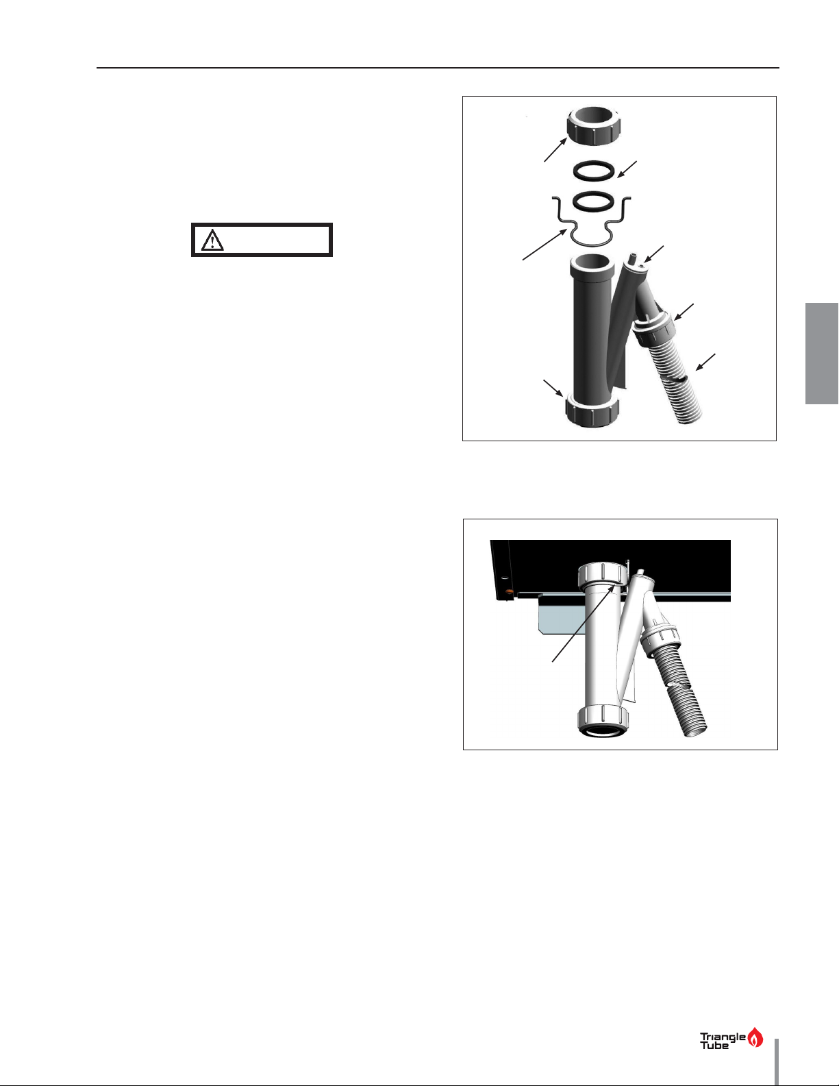
1. Ensure condensate drain assembly is firmly secured
to bottom of the unit. See Fig. 1 on the right. Ensure
the retention clip is secure. See Fig. 2 (Solo Models
only).
CLIP
Do not operate the boiler without the
factory-supplied condensate drain assembly
installed. Operation of the boiler without
(FOR S OLO
WALL HUNG
MODELS ONLY
REFER TO
the condensate drain assembly installed can
result in property damage, serious injury, or
death.
2. While the unit is running, check the discharge end
of the condensate drain tubing. Ensure no flue gas
is leaking from the condensate drain tubing by
holding your fingers near the opening.
3. If you notice flue gas leaking, turn off the unit and
contact a qualified service technician to inspect the
unit and condensate drain assembly.
(NOT SHOWN)
CONDENSATE
Fig. 1 - Condensate Drain Assembly
4. Ensure the condensate drain tubing is not blocked
by pouring water through the fill plug port on the
condensate drain assembly. The water should flow
out of the end of the drain tubing. If water does
not appear at the end of the drain tubing, contact
a qualified service technician to inspect and clean
the condensate drain assembly.
5. To fill the condensate drain assembly, remove the
fill plug from the condensate assembly. Slowly pour
water into the assembly until water appears at the
RETENTION CLIP
(FOR SOLO WALL
HUNG MODELS
ONLY
RETAINING NUT
end of the drain tubing. Stop filling and replace plug.
NOTE
To access the condensate siphon on the Floor Standing
models remove the front panel. Gain access to the
siphon by removing the securing screw holding the
siphon cover plate.
Fig. 2 - Condensate Retention Clip -
(Wall Hung Solo Models only)
7
Page 16
8
TITL
WARNING
WARNING
CHAPTER
CHAPTER 3
3.4. 6-Month Maintenance
3 - MAINTENANCE PROCEDURES
3.4.1 Check Water and Gas Piping
1. Remove the boiler front jacket panel and perform
a gas leak inspection per steps 1 through 6 of the
Operating Instructions on page 9. If gas odor or
a leak is detected, immediately shut down the unit
following procedures on page 9. Call a qualified
service technician.
2. Visually inspect for leaks around the internal boiler
water connections and around the heat exchanger.
Visually inspect the external system piping,
circulators, and system components and fittings.
Immediately call a qualified service technician to
repair any leaks.
Have leaks fixed at once by a qualified service
technician. Failure to comply can result in
substantial property damage, serious injury,
or death.
3.4.2 Operate Pressure Relief Valve
3. If water flows freely, release the lever and allow
the valve to seat. Watch the end of the relief valve
discharge pipe to ensure that the valve does
not weep after the line has had time to drain. If
the valve weeps, lift the lever again to clean the
valve seat. If the valve does not properly seat and
continues to weep afterwards, contact a qualified
service technician to inspect the valve.
4. If water does not flow from the valve when you
lift the lever completely, the valve or discharge
line may be blocked. Immediately shut the unit
down per the instructions on page 9. Call a
qualified service technician to inspect the valve
and discharge line.
3.4.3 Check Carbon Monoxide Detectors
Verify that at least two (2) carbon monoxide detectors
with an alarm and battery back-up if hard wired; one in
the mechanical room where the boiler is located and
another installed in the area outside each sleeping
area .
Contact a qualified service technician if carbon
monoxide detectors are not installed or operating
properly.
1. Before proceeding, verify that the relief valve
outlet has been piped to a safe place, avoiding any
possibility of scalding from hot water.
To avoid water damage or scalding, a
discharge line must be connected to the relief
valve outlet and directed to a safe place of
disposal. This discharge line must be installed
by a qualified service technician in accordance
with the INSTINCT installation manual. The
discharge line must be terminated so as
to eliminate possibility of severe burns or
property damage should the valve discharge.
Failure to comply can result in substantial
property damage, serious injury, or death.
2. Read the pressure gauge to ensure the system is
pressurized. Lift the relief valve top lever slightly,
allowing water to relieve through the valve and
discharge piping.
Page 17
FOR YOUR SAFETY, READ BEFORE LIGHTING
OPERATING INSTRUCTIONS
1. STOP! Read the safety information above. This ap-
7. Turn the service switch on the appliance control
pliance is equipped with an ignition device which
panel “ON”.
automatically lights the burner. DO NOT try to
8. Set room thermostat(s) to desired setting(s).
light the burner by hand.
9. The appliance control panel display will show the
2. Set room thermostat(s) to lowest setting. Turn the
current operating status on the Status Line at the
external manual gas valve handle clockwise
bottom of the screen. “Standby” means there is
to “CLOSE” (valve handle must be perpendicular to
no call for heat (all thermostats are satisfied). “CH
gas piping).
Demand” indicates a space heating call has been
3. Turn the service switch on the appliance control
received. “DHW Demand” indicates a domestic hot
panel OFF.
water call has been received. A flame icon will be
4. Remove the front jacket panel on the unit.
displayed when the unit is fired.
5. Wait five (5) minutes to clear out any gas. If you
10. If the unit will not operate, follow the instructions
then smell gas in the jacket enclosure or around
“To Turn Off Gas to Appliance” and call your service
the unit, STOP! Follow “B” in the safety information
technician or gas supplier.
above. If you don’t smell gas, go to the next step.
11. Replace the front jacket panel. Make sure the panel
6. Turn the external manual gas valve handle count-
is seated firmly in place and all mounting screws
er clockwise to “OPEN” gas supply (valve
are tightened.
handle shall be parallel to gas piping).
TO TURN OFF GAS TO APPLIANCE
CHAPTER 4
CHAPTER 4 - OPERATING INSTRUCTIONS
WARNING
If you do not follow these instructions exactly, a fire or explosion may result,
causing substantial property damage, serious injury, or death.
A. This appliance does not have a pilot. It is equipped C. Use only your hand to turn the external manual
with an ignition device which automatically lights
the burner. DO NOT try to light the burner by hand. by hand, don’t try to repair it; call a qualified service
B.
BEFORE OPERATING, smell all around the appliance
area for gas. Be sure to smell next to the floor
because some gas is heavier than air and will settle D. Do not use this appliance if any part has been
on the floor.
WHAT TO DO IF YOU SMELL GAS
• Do not try to light any appliance.
Do not touch any electric switch; do not
•
use any phone in your building
Immediately call your gas supplier from a
•
neighbor’s phone. Follow the gas supplier’s
instructions.
If you cannot reach your gas supplier, call
•
the fire department.
gas valve. Never use tools. If the valve will not turn
technician. Force or attempted repair may result in
a fire or explosion.
under water. Immediately call a qualified service
technician to inspect the appliance and to replace
any part of the control system and any gas control
which has been under water.
1. Set the room thermostat to lowest setting.
2. Turn the service switch on the appliance control
panel to “OFF”
3. Turn the external manual gas valve handle clockwise
to “CLOSE”.
9
Page 18

INTENTIONALLY LEFT BLANK
Page 19
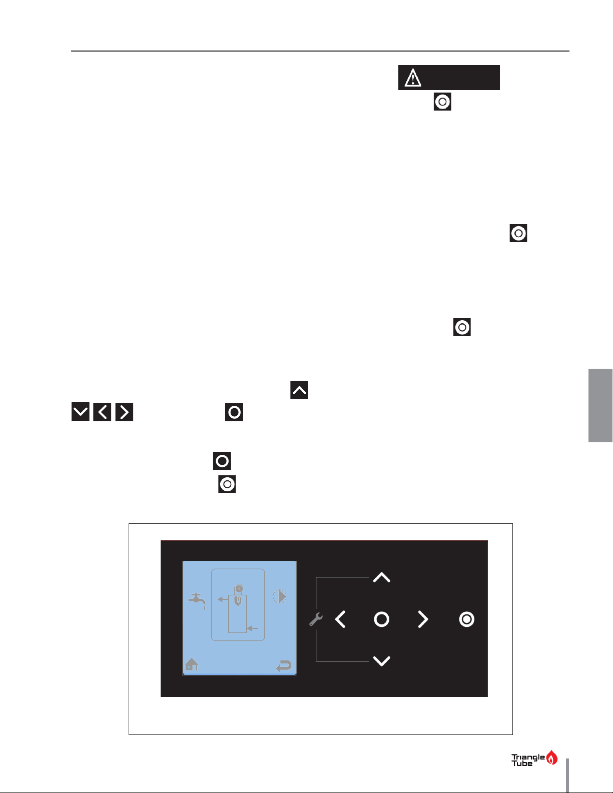
CHAPTER 5 - CTRLMAX OPERATION
DANGER
CHAPTER 5
The CTRLMax Boiler Management System is designed
to be flexible yet easy to use. CTRLMax monitors and
controls the INSTINCT to provide heat as efficiently as
possible.
All CTRLMax features are easy to use through a graphical display where information is presented either graphically or in plain English, so code charts are not required.
below
Fig. 3
INSTINCT Solo fired for a domestic hot water demand.
5.1. CTRLMax Navigation
The CTRLMax navigation is performed through soft keys
that react to the touch and emit a short beep when tapped.
Exert a light and short touch (tap) on the soft
keys to activate their function. Holding the
touch too long will not generate any reaction
from the CTRLMax, unless it is a combination of
soft keys meant to be touched simultaneously
for a determined duration, as instructed in this
manual. The arrow keys can also be held longer
Navigation is performed through four arrow soft keys
, , with a center soft key (OK /Reset func-
tions) for making selections and entering information.
The Main Menu can be entered from the Home Screen
shows an CTRLMax display example of the
NOTICE
to increase or decrease values faster.
When touching the
down but is not isolated from power supply.
Therefore, live current is still present in the
unit. For your safety, disconnect electrical
power supply to the unit before servicing or
making any electrical connections to avoid
,
possible electric shock hazard. Failure to do
so can cause serious injury, or death.
• When shutting down using the
key, the appliance will not react to any heat
demand. However, the basic appliance
protection functions (such as frost protection,
etc.) remain active.
• In addition, the arrow soft keys are no longer
illuminated, and the
The menu system utilizes icons to represent each
selection. The current selected menu is displayed as
a reversed image with a text description shown at the
top of the display. Menus can be entered by selecting
the the desired icon (highlights) using the arrow soft
keys.
soft key, the unit shuts
NOTICE
dimmed.
soft key lighting is
soft
by touching the center soft key .
To shut down the unit, touch the
soft key.
DHW
DHW Demand
Fig. 3 - CTRLMax User Interface
11
Page 20
CHAPTER 5 - CTRLMAX OPERATION
12
186°F
DHW
156°F
Target = 186°F
DHW Demand
EZ Setup
CH / DHW Operation
Select Language
Boiler Information
Heating Enabled
Select Language
Boiler Information
Lockout Histo ry
English
Deutsch
CHAPTER 5
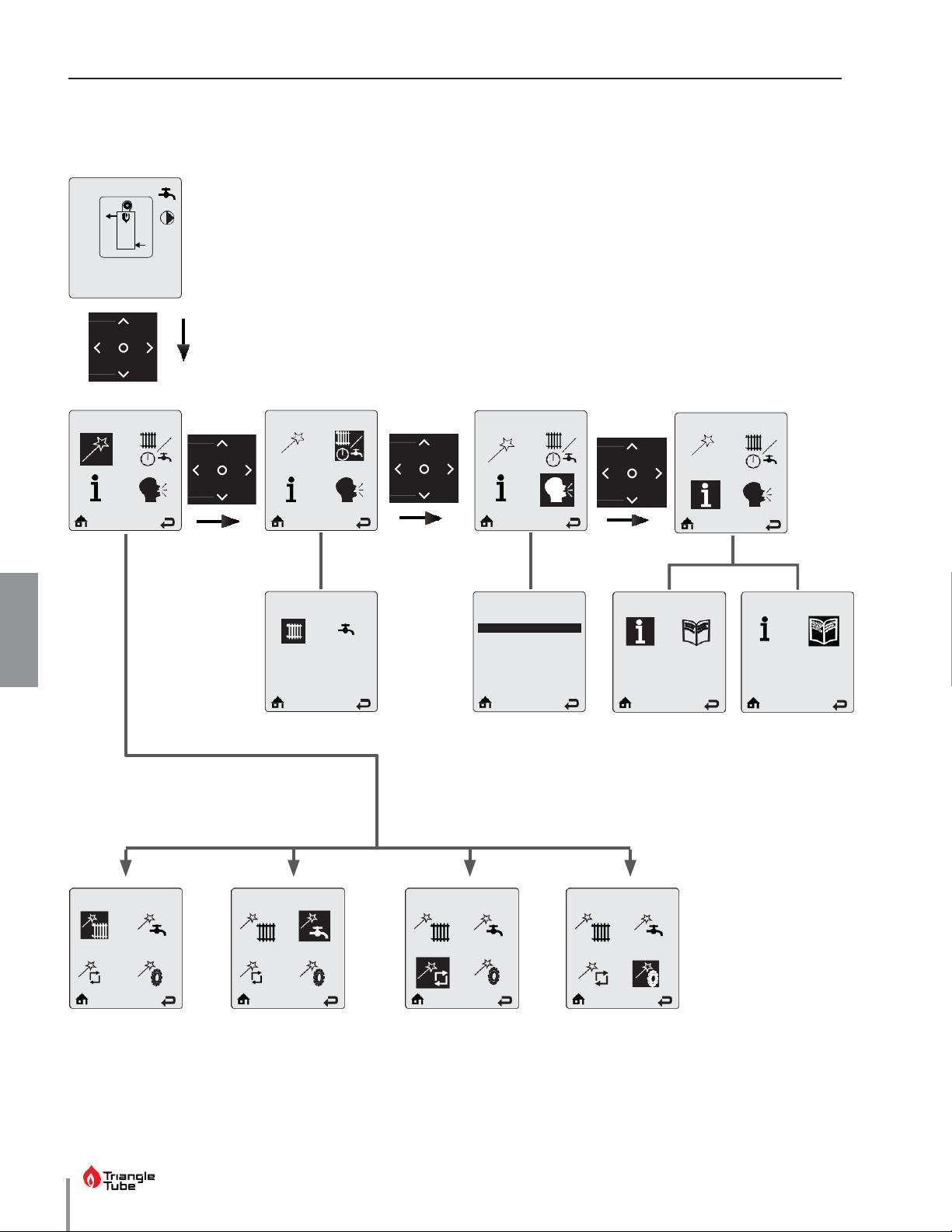
5.2. CTRLMax Menu Structure
Heating EZ Setup DHW EZ Setup
Français
Nederlands
Español
Italiano
EZ Setup Reset
Display EZ Setup
Page 21
CHAPTER 5 - CTRLMAX OPERATION
Radiator icon:
indicates that a central heating
call has been received. A small number 1 or 2
indicates
A
flame
Basic information:
The user can toggle
Combi
186°F
DHW
Faucet icon:
indicates that a DHW call has been
Circulator
powered.
156°F
through items using the
and soft
keys
Outdoor,
DHW flow.
Target = 186°F
DHW Demand
Status line:
displays the current operating state of
the boiler.
CHAPTER 5
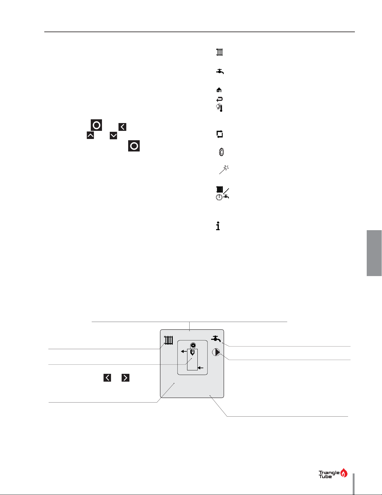
5.3. Home Screen
The Home Screen presents status information in a very
user friendly way so that the current state of the boiler
can be quickly accessed.
• Screen backlight - it will illuminate when any soft
key is touched, and remain illuminated for five minutes.
• Screen brightness
- it can be adjusted at the
Home screen by touching and holding simulta-
neously the and soft keys for 2 seconds.
Touch the and soft key to increase or de-
crease the contrast. Touch
to end the process.
Main Icons of CTRLMax display
•
Central Heating
to central/space heating.
• DHW - indicates information related to
Domestic Hot Water.
•
•
Home
Back
- to go back to the home screen.
- to go back to the previous screen.
• Warm Weather Shutdown - displays on the
home screen when the outdoor temperature
reaches the Warm Weather Shutdown temperature.
•
Reset - to reset the system to the factory
settings.
•
Settings - to access controller settings
(language, units, etc.).
•
Easy Setup - to quickly adjust the most
common settings.
•
CH/DHW operation - to enable/disable the
central/space heating or Domestic Hot Water
functions
- indicates information related
•
Information
- to get information on the boiler.
The INSTINCT is represented in the center of the Home Screen. Basic operating infor-
mation such as supply and return temperatures are displayed as well as current burner
which CH calls are active
flame symbol
to view Target, Supply, Return, Domestic,
is displayed when the unit is fired. The
size changes to indicate the current firing rate.
System and Mix Zone temperatures,
The model is indicated at the top of the screen.
status.
received.
icons:
indicate which circulators are currently
13
Page 22

CHAPTER 5 - CTRLMAX OPERATION
14
CHAPTER 5
5.4. Status Line Messages
Standby - Indicates that the INSTINCT is ready to
respond when a demand is received.
CH Demand - A central heating call has been received.
DHW Demand - A domestic hot water call has been
received.
CH/DHW Demand - Central heating and domestic hot
water calls are being received simultaneously. Both calls
are being satisfied simultaneously because domestic
hot water priority has been disabled.
DHW Priority - Central heating and domestic hot water
calls are being received simultaneously. Domestic hot
water call is being satisfied first because it has priority
over central heating calls.
PriorityTimeout - Central heating and domestic hot water
calls are being received simultaneously. The domestic hot
water priority time limit has been exceeded. Priority will
now switch back and forth between central heating and
domestic hot water calls until one call is satisfied.
DHW Post Pump
is/are running to remove heat from the INSTINCT at the
completion of a call.
Freeze Protection - The burner is fired because the
freeze protection feature has been activated. Freeze
protection will end once the supply/system water
temperature is raised to 60°F [16°C].
Boiler Protection - The burner firing rate is being
reduced because of an excessive difference between
the boiler supply and return temperatures. The firing
rate will begin increasing once the temperature
difference is less than 45°F [25°C].
Low Water Pressure - The system pressure has
dropped to 10.1 psi. The INSTINCT will still respond to
calls until the pressure drops below 7.2 psi. Increase
system pressure to 14.5 psi to clear Low Water Pressure
warning
Lockout Description - The lockout which currently
has the INSTINCT shut down is displayed.
- The domestic hot water circulator(s)
External Demand - An external modulation call has
been received.
Slave Operation
system.
Manual Operation - The burner or circulators have
manually been enabled in the Installer Menu.
CH Burner Delay - The burner will not fire until the call
blocking time has elapsed.
DHW Burner Delay - The burner will not fire until the
call blocking time has elapsed.
CH Setpoint Reached - The burner is not fired because
the supply/system water temperature exceeds the
setpoint. The central heating circulator(s) continue(s) to
operate and the burner will fire again once the supply/
system water temperature drops below the setpoint.
DHW Setpoint Reached - The burner is not fired
because the supply/system water temperature exceeds
the setpoint. The domestic circulator(s) continue(s) to
operate and the burner will fire again once the supply/
system water temperature drops below the setpoint.
- The INSTINCT is a slave in a cascade
CH Post Pump - The central heating circulator(s) is/
are running to remove heat from the INSTINCT at the
completion of a call.
Page 23
CHAPTER 5 - CTRLMAX OPERATION
Combi
186°F
DHW
156°F
Target = 186°F
DHW Demand
Touch center soft key
EZ Setup
The EZ Setup menu can
be
this icon.
Currently selected menu
The Boiler Information
Menu
by selecting this icon.
The Home Screen icon at
the bottom of each screen
returns
when selected.
The Previous Screen icon at the
bottom of each screen returns to
the previous screen when selected.
CHAPTER 5
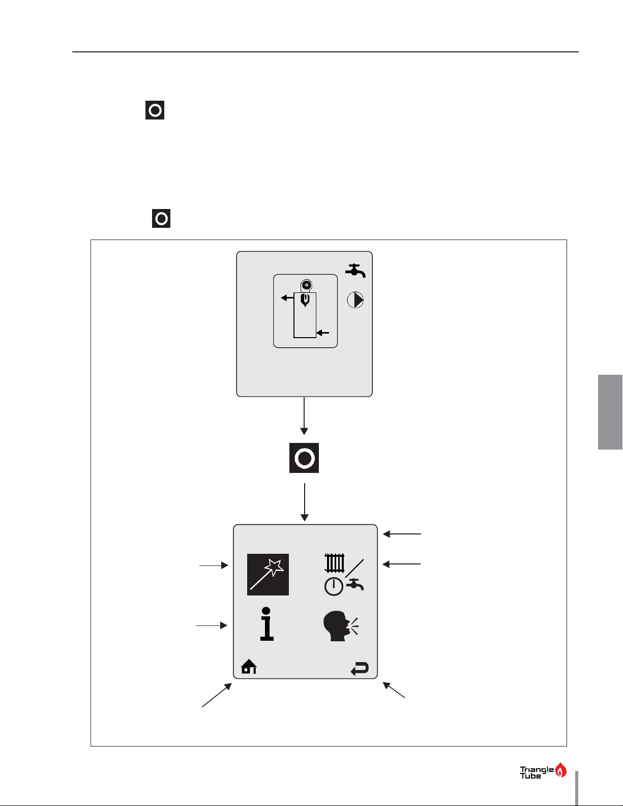
5.5. Main Menu
The Main Menu can be entered from the Home Screen
by touching the soft key.
The menu system utilizes icons to represent each se-
lection.
The currently selected menu is displayed as an inversed im-
5.6. EZ Setup
The EZ Setup menus provide a simple way to quickly
customize CTRLMax for each installation. EZ Setup
prompts the user to make selections which allows the
INSTINCT to be setup very quickly without searching
through long lists of settings and manually making
adjustments.
age with a text description shown at the top of the display.
Menus can be entered by scrolling through the icons
using the arrow soft keys, highlighting the desired icon
and touching the soft key.
accessed by selecting
can be accessed
to the Home Screen
The CH / DHW Operation
Menu can be accessed by
selecting this icon.
15
Page 24
CHAPTER 5 - CTRLMAX OPERATION
16
CHAPTER 5
5.7. CH / DHW Operation
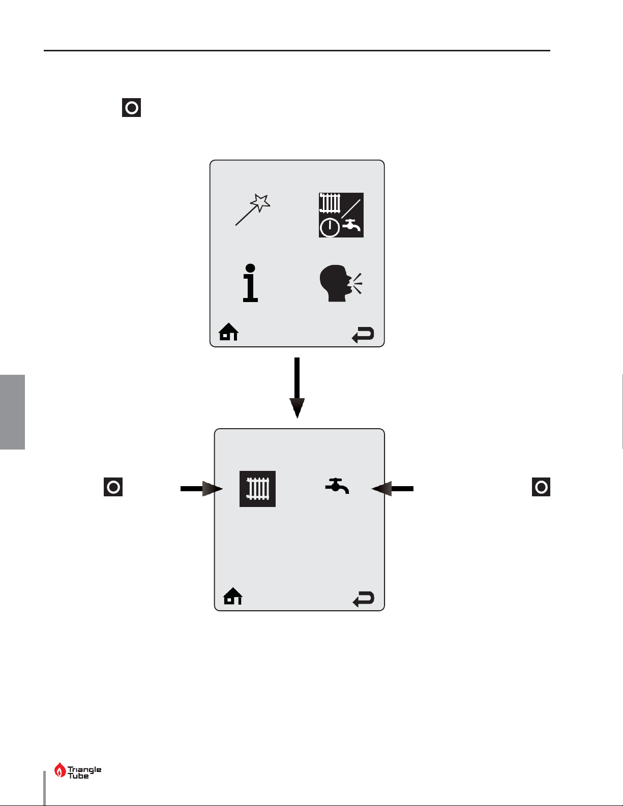
The CH / DHW Operation Menu can be entered from the Main Menu by selecting the CH / DHW Operation icon
and touching the
heating or domestic hot water functions of the INSTINCT.
soft key. The CH / DHW Operation Menu provides a simple way to disable either the central
CH / DHW Operation
Heating Operation can be
enabled and disabled by selecting the radiator icon and
touching the soft key to
toggle operation between
enabled and disabled.
A radiator icon with an X
through it indicates that the
heating function is disabled.
This icon is also displayed on
the Home Screen when disabled.
Heating Enabled
Domestic Hot Water Operation can be enabled and disabled by selecting the faucet
icon and touching the
soft key to toggle operation
between enabled and disabled.
A faucet icon with an X
through it indicates that the
domestic hot water function
is disabled.
This icon is also displayed on
the Home Screen when disabled.
Page 25

CHAPTER 5 - CTRLMAX OPERATION
Select Language
English
Deutsch
CHAPTER 5
5.8. Language Selection
The Select Language Menu can be entered from the Main Menu by selecting the Select Language icon and touch-
ing the soft key. The Select Language Menu provides a simple way to select the language used on the display
(nine different languages: English, French, Dutch, Spanish, Italian, German, Czech, Polish and Russian).
Select Language
Touch the
to select the required lan-
guage then touch the
soft key to store the setting
and
soft keys
Français
Nederlands
Español
Italiano
17
Page 26
CHAPTER 5 - CTRLMAX OPERATION
18
Boiler Setpoint
--
CHAPTER 5
5.9. Boiler Information
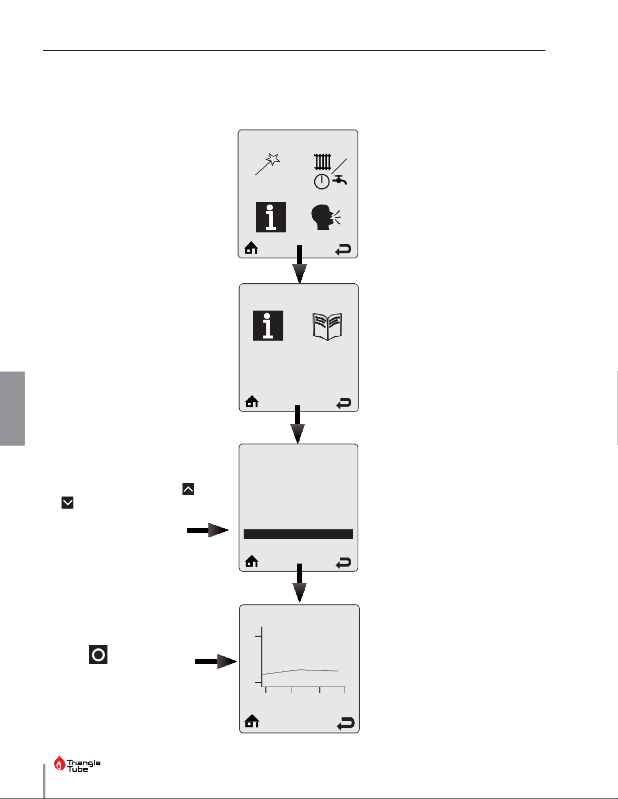
Boiler Information can be viewed by selecting the Boiler Information icon and pressing the OK button. Boiler
Information provides real time operating information of the INSTINCT.
Boiler Information
Boiler Information displays six boiler readings at a time. Each line contains an information item followed
by its current value. Touch the
and soft key to scroll through
additional information items.
Some information items include a
logging function.
Select the information item then
touch the soft key to view its
graph.
One sample is recorded every 12
minutes to produce a graph of the
Boiler Information
Boiler Information
Boiler Status
Heating Call
DHW Call
Boiler Firing Rate
Ionization current
Boiler Setpoint
194
68
-24.00
-16.00
Standby
-8.00
No
No
0µA
0.00
--
The following items have a logging
Boiler Firing Rate
Ionization Current
Boiler Setpoint
Boiler Supply Temperature
Boiler Return Temperature
Boiler Flue Temperature
Outdoor Temperature
DHW Storage Temperature
External Modulation Signal
Pressure
function:
•
•
•
•
•
•
•
•
•
•
last 24 hours.
Page 27

CHAPTER 5 - CTRLMAX OPERATION
Displays the number of domestic hot water ignitions since the unit was installed.
CHAPTER 5
5.9.1 Information Items
Information Item
Boiler Status
Heating Call
DHW Call
Boiler Firing Rate
Ionization Current
Boiler Setpoint
Supply Temp.
Return Temp.
Boiler Flue Temp.
Description
Displays the current operating state of the INSTINCT. This is the same as the status line on the home screen.
Displays if a central heating call is present.
Displays if a domestic hot water call is present.
Displays the current firing rate of the INSTINCT.
Displays the current flame ionization current from the ignitor.
Displays the current setpoint of the INSTINCT.
Displays the current supply temperature of the INSTINCT.
Displays the current return temperature to the INSTINCT.
Displays the current flue temperature of the INSTINCT.
Outdoor Temp.
DHW Storage Temp.
External Modulation Signal
Pressure
CH Ignitions
CH Runtime
DHW Ignitions
DHW Flowrate
DHW Runtime
Displays the current outdoor temperature.
Displays the current DHW storage temperature when Indirect Water Heater
Sensor PSRKIT22 is installed.
Displays the current external modulation signal being received from an external
controller.
Displays the current system water pressure.
Displays the number of central heating ignitions since the unit was installed.
This counter increases in increments of twenty.
Displays the number of hours the INSTINCT has run for a central heating call since
the unit was installed.
This counter increases in increments of twenty.
Displays the Domestic Hot Water flow rate
Displays the number of hours the INSTINCT has run for a domestic hot water call
since the unit was installed.
Mix Zone Temperature
Displays the current low temperature mix zone temperature.
19
Page 28
CHAPTER 5 - CTRLMAX OPERATION
20
1. Blower speed
5h ago
CHAPTER 5
5.10. Lockout History
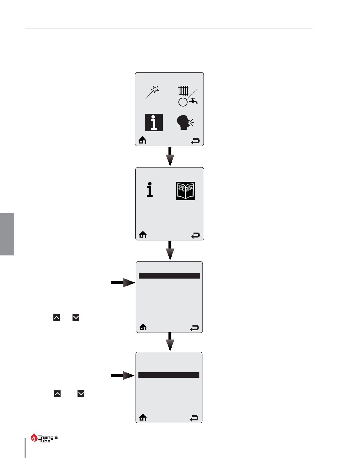
Lockout History can be viewed by selecting the Lockout History icon and pressing the OK button. The Lockout
History Screen lists the last eight lockouts along with how long ago they occurred.
Boiler Information
Lockout History displays the
last eight lockouts. The newest
Lockout History
Lockout History
lockout is displayed at the top of
2.
the screen.
The lockout message is followed
by how long ago the error
occurred.
Touch the and soft keys to
scroll through additional lockouts.
DHW Sensor Open 2h ago
3.
Sensor Drift
4.
No error
5.
No error
6.
No error
25 h ago
27 h ago
27 h ago
27 h ago
Lockout Details displays the
lockout at the top of the screen
followed by a snapshot of the
boiler information recorded at the
time of the lockout.
Touch the and soft keys
to scroll through additional
Lockout Details
Blower speed
Boiler Status
Heating Call
DHW Call
Boiler Firing Rate
Ionization current
--
--
44%
44µA
information items.
Page 29
CHAPTER 5 - CTRLMAX OPERATION
186°F
156°F
Target = --
Low Water
CHAPTER 5
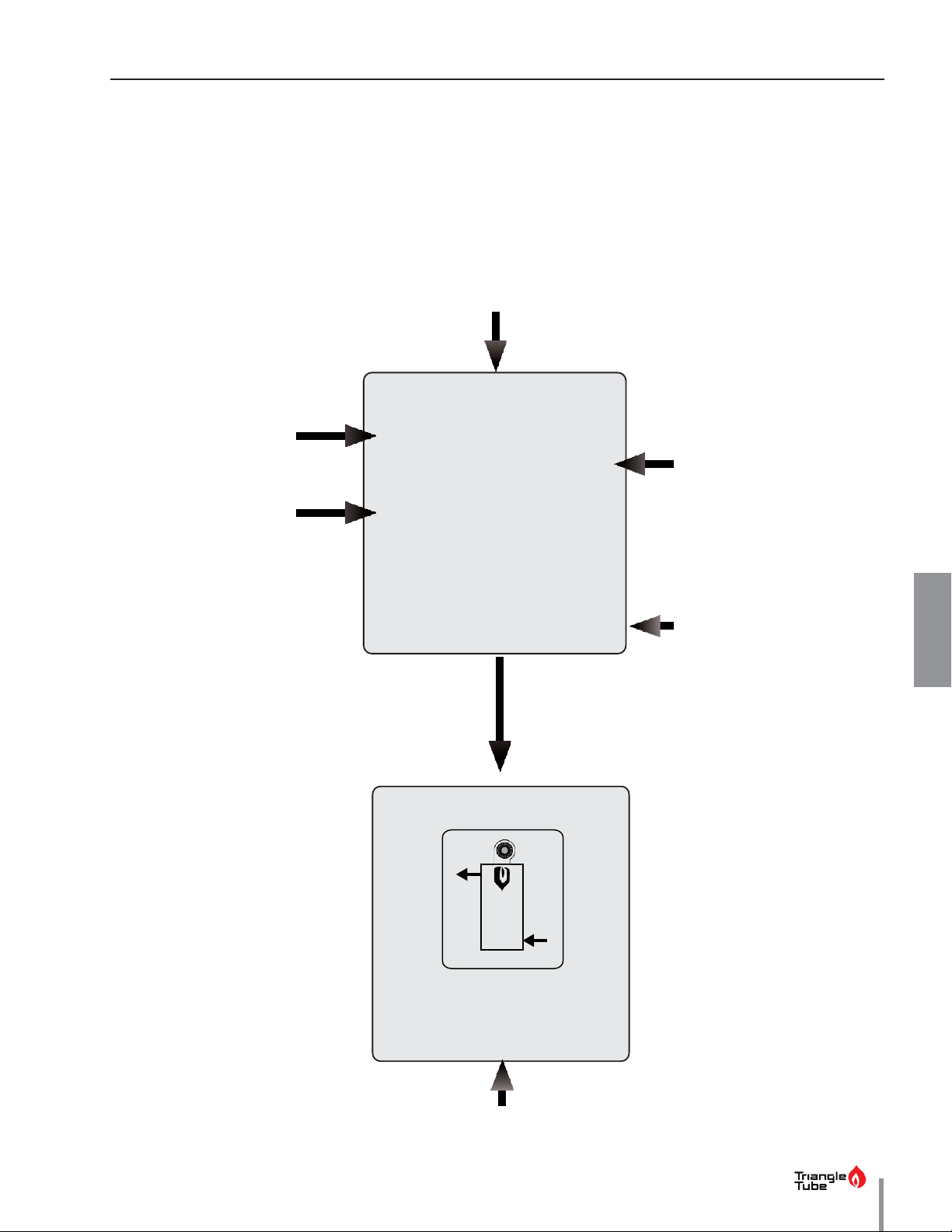
5.10.1 Lockout Screen
If a problem occurs, the Lockout Screen replaces the Home Screen. The backlight will remain on until the lockout
is reset.
Pressing any arrow button will return to the Home Screen so that additional troubleshooting can be performed. See
Sections 5.10.2 on page 22 and 5.10.3 on page 23
for a list of lockouts and descriptions.
The lockout message is displayed at the top of the screen
The first sentence gives a
description of the lockout.
The third sentence tells how
to reset the lockout
Water pressure has fallen below
range. Boiler will automatically
reset once water level returns to
Low Water
an acceptable operating level.
Increase pressure to normal
normal.
If problem persists,
call for service
The second sentence gives a
possible cure for the lockout.
E37
The lower right corner displays
the lockout reference code
Press any
ARROW
Button
Press any ARROW button to
return to the Home Screen
while locked out.
The Main Menu can then be
entered from the Home Screen
to help diagnose the problem.
Select the Home Screen icon
at the bottom of any menu
screen to return to the Lockout
Screen.
The status line now displays the lockout
21
Page 30

CHAPTER 5 - CTRLMAX OPERATION
22
Code
E1
E2
E3
E5
E8
E9
E13
E15
E16
E17
E18
E19
E21
E30
E31
E43
E44
E47
E80
E83
E87
CHAPTER 5
5.10.2 Manual Reset Lockouts
Lockout Message
Failed Ignition The burner failed to light after 5 ignition attempts.
False Flame Flame detected prior to ignition.
High Boiler Temperature
Blower Speed
Flame Circuit Error
Gas Valve Circuit Error
Reset Limit Reached
Sensor Drift
Supply Sensor Stuck Supply sensor reading is not changing.
Return Sensor Stuck
Description
Boiler temperature has reached 210°F [99ºC] or 102°F [39°C].
Blower is not at correct speed or speed signal is not being received by control module.
Flame circuit test failed.
Gas valve circuit test failed.
Resets are limited to 5 every 15 minutes.
Supply or return sensor reading has drifted.
Return sensor reading is not changing.
Sensor Failure
Flame Failure During Startup Phase
Internal Control Fault
Supply Sensor Shorted
Supply or return sensor reading changed very rapidly.
Flame lost after startup
A / D conversion error.
A short circuit has been detected in the boiler supply temperature sensor circuit.
Supply Sensor Open An open circuit has been detected in the boiler supply temperature sensor circuit.
Return Sensor Shorted
Return Sensor Open
Water Pressure Sensor Error
A short circuit has been detected in the boiler return temperature sensor circuit.
An open circuit has been detected in the boiler return temperature sensor circuit.
Water pressure sensor is disconnected or broken.
Return > Supply Return temperature is higher than supply temperature.
Delta T Protection
External Limit Open
Excessive difference between boiler supply and return temperatures has occured 5 times
An external manual reset limit has opened
Page 31

CHAPTER 5 - CTRLMAX OPERATION
CHAPTER 5
5.10.3 Automatic Reset Blocking Lockouts
Code Lockout Message
E7
E12
E25
E32
E33
E34
E37
E45
E46
E76
E77
High Flue Temperature
Internal Control Fault
Internal Control Fault
DHW Sensor Shorted
DHW Sensor Open
Low Voltage
Low Water
Flue Sensor Shorted
Flue Sensor Open
External Limit Open
High Mix Circuit Temperature
Flue temperature exceeds high limit.
Line voltage has fallen below an acceptable operating level.
Mix circuit temperature exceeds Mix zone high limit setting.
Description
EEPROM misconfiguration.
CRC check error.
A short circuit has been detected in the DHW temperature sensor circuit.
An open circuit has been detected in the DHW temperature sensor circuit.
Water pressure has fallen below 7.2 psi.
A short circuit has been detected in the boiler flue temperature sensor circuit.
An open circuit has been detected in the boiler flue temperature sensor circuit.
An external automatic reset boiler limit has opened.
E78
E79
E81
E82
E89
E90
E91
E92
E93
E94
E95
E96
E97 Cascade Mismatch Cascade configuration has changed.
Mix Circuit Sensor Shorted
Mix Circuit Sensor Open
Sensor Drift
Delta T Protection
Incorrect Setting
Firmware Mismatch
System Sensor Shorted
System Sensor Open
Outdoor Sensor Shorted
Internal Display Fault
Supply Sensor Error
Outdoor Sensor Open
Supply and return temperatures are not equal.
Excessive difference between the boiler supply and return temperatures.
A parameter setting is in conflict with another setting.
Control module and display firmware versions are incompatible.
An open circuit has been detected in the system temperature sensor circuit.
Supply sensor reading is invalid.
A short circuit has been detected in the mix circuit temperature sensor circuit.
An open circuit has been detected in the mix circuit temperature sensor circuit.
A short circuit has been detected in the system temperature sensor circuit.
A short circuit has been detected in the outdoor temperature sensor circuit.
Display memory error.
An open circuit has been detected in the outdoor temperature sensor circuit.
E98
E99
Cascade Bus Error
Controller Bus Error
Communication between boiler display and control module has been lost.
Communication with other boilers has been lost.
23
Page 32
24
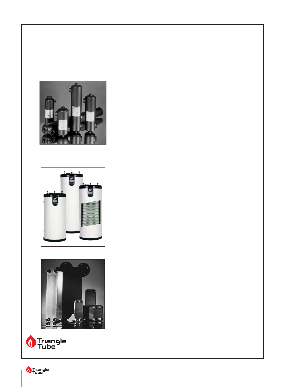
Additional quality water heating equipment available
Maxi-Flo Pool and Spa Heat Exchangers
from Triangle Tube
• Constructed of high quality corrosion resistant
stainless steel (AISI 316) or titanium
• Specially designed built-in flow restrictor to assure
maximum heat exchange
• Compact and light weight
• Available in 8 sizes to accommodate any size pool
or spa
SMART 316 Indirect Fired Water Heaters
TTP Brazed Plate Heat Exchangers
Triangle Tube
Tel: (856) 228 8881 - Fax: (856) 228 3584 - E-mail: [email protected]
• Exclusive Tank-in-Tank design
• Stainless steel construction
• Available in 7 sizes
• Limited LIFETIME residential warranty
• 6 Year limited commercial warranty
• Self cleaning/self descaling design
• For domestic water, snow melting, radiant floor
• Plates made of stainless steel, with 99.9 % copper
brazing, ensuring a high resistance to corrosion
• Self cleaning and self descaling
• Computerized sizing available from Triangle Tube
• Available in capacities from 25,000 BTU/hr to
5,000,000 BTU/hr
- 1240 Forest Parkway, Suite 100, West Deptford NJ 08066
 Loading...