


TRIUMPH SERIES
GAS-FIRED HIGH-EFFICIENCY BOILERS
Models:
• T300
• T399
• T425
Installation Date:
TRIAD Boiler Systems, Inc.
1099 Atlantic Drive, Unit 2
West Chicago, IL 60185
Phone: 630.562.2700
Fax: 630.562.2800
www.triadboiler.com
Version 1.0 / 5-19-10
______________________


Table of Contents
I. Product Description 2
II. Specications 2
III. Before Installing 3
IV. Locating The Boiler 3
V. Air For Ventilation 5
VI. Venting 7
Vent System Design 7
Removing An Existing Boiler From Common Chimney 16
Vent Adapter Installation 17
Assembly of Stainless Steel Venting System 19
Triad Concentric Venting Assembly 23
Condensate Trap & Drain Line 31
VII. Gas Piping 33
VIII. System Piping 34
General System Piping Precautions 34
System Design 34
Standard Piping Installation Requirements 43
Piping For Special Situations 44
IX. Wiring 47
X. Start-up and Checkout 51
XI. Operation 57
XII. Service and Maintenance 62
XIII. Troubleshooting 64
XIV. Parts 68
Appendix A. Boiler Operating Parameters
Overview 84
Entering The Access Code 84
Changing Parameters 85
Field Adjustable Parameters 88
Communication, Fan Speed and Error Modes 90
Appendix B. Component Test Procedures
Flame Signal Check 92
NTC Temperature Sensors 92
Appendix C. Special Requirements For Side-Wall Vented
Appliances In The Commonwealth of Massachusetts 94
1

I Product Description
The TRIUMPH is an aluminum gas red condensing boiler designed for use in forced hot water heating systems requiring supply water temperatures of 180°F or less. This boiler may be vented vertically or horizontally with combustion air
supplied from outdoors. This boiler is not designed for use in gravity hot water systems or systems containing signicant
amounts of dissolved oxygen.
II Specications
Figure 2.1: General Conguration
Table 2.2: Specications
MODEL
T300 5 300 100 265 230 93.1 88.2 33-3/8” 4” 4”
T399 7 399 106 350 304 91.7 87.6 40-1/8” 5” 5”
T425 7 425 106 367 320 90.9 86.5 40-1/8” 5” 5”
PERFORMANCE RATINGS ARE THE SAME FOR NATURAL AND LP.
NO. OF
SECTIONS
MAXIMUM
INPUT
MBH
MINIMUM
INPUT
MBH
GROSS
OUTPUT
MBH
IBR NET
RATING
MBH
COMBUSTION THERMAL “B” INLET “C” EXHAUST
HIGH FIRE
EFFICIENCY %
“A”
LENGTH
VENT COLLAR
DIAMETERS (IN.)
2

III Before Installing
1) Safe, reliable operation of this boiler depends upon installation by a professional heating contractor in strict
accordance with this manual and the authority having jurisdiction.
• In the absence of an authority having jurisdiction, installation must be in accordance with this manual and
the National Fuel Gas Code, ANSI Z223.1. In Canada, installation must be in accordance with the
B149.1 Installation Code
• Where required by the authority having jurisdiction, this installation must conform to the Standard for
Controls and Safety Devices for Automatically Fired Boilers (ANSI/ASME CSD-1).
2) TRIUMPH boilers utilize aluminum heat exchangers constructed, tested, and stamped in accordance with
ASME Boiler and Pressure Vessel Code Case 2382. Some jurisdictions which require ASME boiler construction do not recognize this Code Case and may not approve the installation of an aluminum boiler. Consult the
authority having jurisdiction before installing this boiler.
3) Read Section VI to verify that the maximum combustion air and exhaust pipe lengths will not be exceeded in
the planned installation. Also verify that the vent terminal can be located in accordance with Section VI.
4) Make sure that the boiler is correctly sized:
• For heating systems employing convection radiation (baseboard or radiators), use an industry accepted
sizing method such as the I=B=R Heat Loss Calculation Guide (Pub. #H21 or #H22) published by the
Hydronics Institute in Berkely Heights, NJ.
• For new radiant heating systems, refer to the radiant tubing manufacturer’s boiler sizing guidelines.
• For systems that incorporate other indirect water heaters, refer to the indirect water heater manufacturer’s
instructions for boiler output requirements.
• Long runs of venting may reduce the maximum input of the boiler by as much as 10% (See Section VI for
more information.
5) Make sure that the boiler received is congured for the correct gas (natural or LP).
6) Make sure that the boiler is congured for use at the altitude at which it is to be installed.
NOTICE
This product must be installed by a licensed plumber or gas tter when installed within the
Commonwealth of Massachusetts. See Appendix C for additional important information about
installing this product within the Commonwealth of Massachusetts.
IV Locating the Boiler
1) Observe the minimum clearances shown in Figure 4.1. These clearances apply to both combustible and non-
combustible materials. Observe the minimum clearances to combustibles for vent pipe shown in Table 4.2.
2) Note the recommended service clearances in Figure 4.1. The recommended service clearances may be reduced to the minimum combustible clearances provided:
a. Access to the front of boiler is provided through a door.
b. Access is provided to the condensate trap and ttings/trim located on the back of the boiler.
3) Boiler may be installed on non-carpeted combustible surface.
4) The relief valve must be installed in the factory specied location.
5) The boiler should be located so as to minimize the length of the vent system.
3

Figure 4.1: Clearances To Combustible Or Non-combustible Material
Table 4.2: Clearances From Vent Piping To Combustible Construction
TYPE OF VENT PIPE PIPE DIRECTION ENCLOSURE
HEAT FAB SAF-T VENT
PROTECH FASNSEAL
Z-FLEX Z-VENT III
METAL-FAB CORR-GUARD
HEAT FAB SAF-T VENT
PROTECH FASNSEAL
Z-FLEX Z-VENT III
METAL-FAB CORR-GUARD
HEAT FAB SAF-T VENT
PROTECH FASNSEAL
Z-FLEX Z-VENT III
METAL-FAB CORR/GUARD
100/150MM
CONCENTRIC VENTING
VERTICAL OR
HORIZONTAL
HORIZONTAL OR VERTICAL
WITH OFFSETS
VERTICAL WITH NO OFFSETS ENCLOSED ON ALL FOUR SIDES
VERTICAL OR HORIZONTAL ENCLOSED ON ALL FOUR SIDES 0”
AT LEAST ONE SIDE OPEN,
COMBUSTIBLE MATERIAL ON A
MAXIMUM OF THREE SIDES
ENCLOSED ON ALL FOUR SIDES
4
MINIMUM CLEARANCE
TO COMBUSTIBLE
MATERIAL
1”
2-1/2”
2-1/2”

6) The combustion air piping must terminate where outdoor air is available for combustion and away from areas that
will contaminate combustion air. Avoid areas near chemical products containing chlorine, chloride based salts,
chloro/uorocarbons, paint removers, cleaning solvents and detergents.
WARNING
OUTDOOR COMBUSTION AIR MUST BE PIPED TO THE AIR INTAKE. NEVER PIPE COMBUSTION
AIR FROM AREAS CONTAINING CONTAMINATES SUCH AS SWIMMING POOLS AND LAUNDRY
ROOM EXHAUST VENTS. CONTAMINATED COMBUSTION AIR WILL DAMAGE THE BOILER
AND MAY CAUSE PROPERTY DAMAGE, PERSONAL INJURY OR LOSS OF LIFE.
V Air for Ventilation
Air for combustion must always be obtained directly from outdoors, however sufcient air for ventilation must
still be provided in the boiler room. Air for ventilation is required to keep various boiler components from over-
heating and is always obtained from indoors. To ensure an adequate ventilation air supply, perform the following
steps:
Step 1: Determine whether the boiler is to be installed in a conned space - A conned space is dened by the
National Fuel Gas Code as having a volume less than 50 cubic feet per 1000 BTU/hr input of all appliances
installed in that space. To determine whether the boiler room is a conned space:
1) Total the input of all appliances in the boiler room in thousands of BTU/hr. Round the result to the next
highest 1000 BTU/hr.
2) Find the volume of the room in cubic feet. The volume of the room in cubic feet is:
Length (ft) x width (ft) x ceiling height (ft)
In calculating the volume of the boiler room, consider the volume of adjoining spaces only if no doors are
installed between them. If doors are installed between the boiler room and an adjoining space, do not consider
the volume of the adjoining space, even if the door is normally left open.
3) Divide the volume of the boiler room by the input in thousands of BTU/hr. If the result is less than 50, the
boiler room is a conned space.
Example:
A T300 and a water heater are to be installed in a room measuring 10ft – 3 in x 10ft with an 8 ft ceiling. The
water heater has an input of 50,000 BTU/hr:
Total input in thousands of BTU/hr = (300,000 BTU/hr + 50,000 BTU/hr) / 1000 = 350 MBTU/hr
Volume of room = 10.25 ft x 10 ft x 8 ft = 820 ft3
820/350 = 2.34. Since 2.34 is less than 50, the boiler room is a conned space.
Step 2a: If the boiler is to be placed in a conned space, provide two openings into the boiler room, one near the
oor and one near the ceiling. The top edge of the upper opening must be within 12” of the ceiling and the bottom
edge of the lower opening must be within 12” of the oor (Fig 5.1). The minimum opening dimension is 3 inches.
• If the TRIUMPH boiler is the only gas-burning appliance in the boiler room, these openings must each
have a minimum free area of 100 square inches.
• If other gas-burning appliances are in the boiler room, size the openings in accordance with the appliance
manufacturer’s instructions or the National Fuel Gas Code. Minimum opening free area is 100 square
inches even if opening requirements for other appliances are less.
5

Figure 5.1: Boiler Installed In A Conned Space, Ventilation Air From Inside
• If the total volume of both the boiler room and the room to which the openings connect is less than 50 cubic feet
per 1000 BTU/hr of total appliance input, install a pair of identical openings into a third room. Connect additional rooms with openings until the total volume of all rooms is at least 50 cubic feet per 1000 BTU/hr of input.
• The “free area” of an opening takes into account the blocking effect of mesh, grills, and louvers. Where screens
are used, they must be no ner than ¼” (4 x 4) mesh.
Step 2b: If the boiler is to be placed in an unconned space, the natural inltration into the boiler room will
provide adequate air for ventilation without additional openings into boiler room.
6

VI Venting
WARNING
Failure to vent this boiler in accordance with these instructions could result in unreliable boiler
operation, severe damage to the boiler or property, personal injury or death:
* Do not attempt to vent this boiler with galvanized, PVC, or any other vent system not listed in Table 4.
* Do not attempt to mix components from different approved vent systems.
* Do not obtain combustion air from within the building.
* Do not install a barometric damper or drafthood on this boiler.
* The vent system for this boiler must not be shared with any other appliance.
* Moisture and ice may form on the surfaces around the vent termination. To prevent deterioration,
surfaces should be in good repair (sealed, painted, etc.)
A. Vent System Design
There are four basic ways to vent this boiler:
• Horizontal (“Side Wall”) Twin Pipe Venting - Vent system exits the building through an outside wall.
Combustion air and ue gas are routed between the boiler and outdoors using separate pipes.
• Vertical Twin Pipe Venting - Vent system exits the building through a roof. Combustion air and ue gas are
routed between the boiler and outdoors using separate pipes.
• Horizontal (“Side Wall”) Concentric Venting - Vent system exits the building through an outside wall.
Concentric venting consists of a “pipe within a pipe”. Flue gas exits the building through the inner pipe and
combustion air is drawn into the boiler through the space between the inner and outer pipe.
• Vertical Concentric Venting - Vent system exits the building through the roof. Concentric venting consists of a
“pipe within a pipe”. Flue gas exits the building through the inner pipe and combustion air is drawn into the boiler
through the space between the inner and outer pipe.
All of these systems are considered “direct vent” because in all of them air for combustion is drawn directly from
the outdoors into the boiler. A description of each of these venting options is listed in Tables 6.1 and 6.5. For
clarity, these vent options are numbered from 1 to 10. One of the vent option columns in Table 6.1 or in Table
6.5 must match the planned vent and air intake system exactly. In addition, observe the following guidelines:
1) Approved vent systems - Use only one of the approved vent systems shown in Tables 6.1 or 6.5. These vent systems
fall into two basic categories:
• Twin Pipe Vent Systems - The standard approved vent systems are made of a special stainless steel alloy (AL29-
4C) for protection against corrosive ue gas condensate. They are designed to provide a gas tight seal at all
joints and seams so that ue gas does not enter the building. Each approved vent system has a unique method for
installation - do not attempt to mix components from different vent systems. A list of approved twin pipe vent
systems is shown in Table 6.4.
• Concentric Vent System - The concentric vent system may only be used on the T300. Each Triad concentric
vent component consists of an inner pipe of polypropylene and the outer pipe of steel. Integral gaskets on each
concentric tting provide a gas tight seal. In this manual, concentric pipe sizes are called out in terms of the inner
and outer pipe nominal diameters in millimeters. For example“100/150mm” pipe consists of a 100mm exhaust
pipe inside a 150mm diameter outer pipe. A list of all Triad concentric vent components is shown in Table 6.10.
The T399 and T425 are supplied with stainless steel vent collar and a separate air intake collar for twin
pipe venting. The T300 may be supplied with either a stainless steel vent adaptor kit (P/N 230557) for twin
pipe venting or a concentric vent adaptor kit (P/N 230556) for concentric venting.
2) Maximum Vent and Air Intake Lengths - The maximum length of the vent air intake piping depends upon the vent
option selected and the boiler size. See Tables 6.1 and 6.5 for the maximum vent lengths. All vent lengths shown in
Tables 6.1 and 6.5 are in addition to one 90° elbow and the termination tting.
7

If additional elbows are desired, the maximum allowable vent length must be reduced by the amount shown in
Table 6.6 for each additional elbow used. Termination ttings are not counted when counting additional elbows.
Example:
A 4” twin pipe vent system is planned for a horizontally vented T300 which has the following components:
4 ft vertical pipe
1 90 elbow
10 ft horizontal pipe
1 90 elbow
6 ft horizontal pipe
1 45 elbow
8 ft horizontal pipe
1 termination tting
The Vent Option #1 column in Table 6.1 describes a horizontal direct vent system using 4” vent pipe. From this
column, we see that a T300 may have a vent length of up to 100ft. The rst 90 elbow and the termination tting are
not considered. From Table 6.6, the equivalent length of the 4” 45 elbow is 4.5ft and the equivalent length of the 4”
90 degree elbow is 8ft. The maximum allowable run of straight pipe on this system is therefore:
100ft – 4.5 ft – 8ft = 87.5ft
Since the planned installation has only 28 ft of straight pipe, the planned vent length is acceptable.
IMPORTANT
The length of the vent system has a minor impact on the maximum input of the boiler. The exact amount of this
de-rate is dependent upon a number of factors including the type of venting, number of joints in the vent system,
and the type of fuel. An estimate of the amount of de-rate that can be expected at the maximum vent length is as
follows:
T300: Less than 10%
T399, T425: Less than 2%
3) Minimum Vent and Air Intake Lengths - Minimum vent length is 4ft. Minimum air inlet length is 2ft.
4) Permitted Terminals for Horizontal Venting (Vent Options 1,2&3)
• Vent Option 1, 2 & 3 - Exhaust terminal is either Triad PN 240513 (4” vent systems) or PN 240514 (5” vent
systems). The air intake terminal is a 90 degree elbow with a rodent screen supplied by the installer. This elbow is
made out of the same material as the rest of the air inlet system (either galvanized or PVC) and is installed as shown
in Figure 6.2.
• Vent Option 4 - Triad P/N 23569.
5) Horizontal Vent and Air Intake Terminal Location - Observe the following limitations on the vent terminal location
(also see Figure 6.7):
• Vent terminals must be at least 1 foot from any door, window, or gravity inlet into the building.
• Maintain the correct clearance and orientation between the vent and air intake terminals. The vent and air intake
terminals must be at the same height and their center lines must be between 12 and 36 inches apart. Both terminals
must be located on the same wall.
• The bottom of the vent and air intake terminals must be at least 12” above the normal snow line. In no case should
they be less than 12” above grade level.
• The bottom of the vent terminal must be at least 7 feet above a public walkway.
8

• Do not install the vent terminal directly over windows or doors.
• The bottom of the vent terminal must be at least 3 feet above any forced air inlet located within 10 feet.
• USA Only: A clearance of at least 4 feet horizontally must be maintained between the vent terminal and gas
meters, electric meters, regulators, and relief equipment. Do not install vent terminal over this equipment. In
Canada, refer to B149.1 Installation Code for clearance to meters, regulators and relief equipment.
• Do not locate the vent terminal under decks or similar structures.
• Top of vent terminal must be at least 5 feet below eves, softs, or overhangs. Maximum depth of overhang is 3 ft.
• Vent terminal must be at least 6 feet from an inside corner.
• Under certain conditions, water in the ue gas may condense, and possibly freeze, on objects around the terminal
including on the structure itself. If these objects are subject to damage by ue gas condensate, they should be
moved or protected.
• If possible, install the vent and air intake terminals on a wall away from the prevailing wind. Reliable operation of
this boiler cannot be guaranteed if the terminal is subjected to winds in excess of 40 mph.
• Air intake terminal must not terminate in areas that might contain combustion air contaminates, such as near
swimming pools. See Section IV for more information on possible contaminates.
TABLE 6.1: SUMMARY OF HORIZONTAL VENTING OPTIONS
VENT OPTION # 1 3 4
CLASSIFICATION USED IN THIS
MANUAL
ILLUSTRATED IN FIGURE 6.2 6.2 6.3
VENT PIPE STRUCTURE
PENETRATION
AIR INTAKE PIPE STRUCTURE
PENETRATION
VENT PIPE SIZE 4” 5” 100/150mm
AIR INTAKE PIPE SIZE 4” 5”
T300 100FT
T399
LENGTH
T425 100FT
MAXIMUM VENT PIPE
T300 100FT N.R. 100FT
T399 100FT
T425
PIPE LENGTH
MAXIMUM INTAKE
VENT TERMINAL
AIR INTAKE TERMINAL 4” 90 ELBOW 5” 90 ELBOW
HORIZONTAL
TWIN PIPE
WALL WALL WALL
WALL WALL WALL
TRIAD PN
204513
HORIZONTAL
TWIN PIPE
N.R. 100FT
100FT
100FT
TRIAD PN
240514
HORIZONTAL
CONCENTRIC
CONCENTRIC
TRIAD 230569
CONCENTRIC
TERMINAL
VENT MATERIAL
AIR INTAKE MATERIAL GALVANIZED OR PVC
APPROVED VENT SYSTEM
SHOWN IN TABLE 6.4
9
TRIAD
100/150mm
VENT
COMPONENTS
SHOWN IN
TABLE 6.10

FIGURE 6.2: HORIZONTAL TWIN PIPE VENTING (VENT OPTIONS 1,2,3)
FIGURE 6.3: HORIZONTAL CONCENTRIC VENTING, T300 ONLY (VENT OPTION 4)
10

TABLE 6.4: PERMISSIBLE STAINLESS STEEL VENT SYSTEMS AND PRINCIPLE VENT
COMPONENTS (VENT OPTIONS 1,2,3,7,8,9)
MANUFACTURER VENT SYSTEM SIZE
SAF-T VENT
HEAT FAB
PROTECH
SYSTEMS
INC.
Z-FLEX
METAL-FAB CORR/GUARD
Notes:
1) T300 requires stainless steel vent adaptor kit P/N 230557 when used with the above stainless steel vent systems.
2) See vent system manufacturer ’s literature for other part numbers that are required such as straight pipe, elbows, restops, and vent sup-
ports.
EZ SEAL
FASNSEAL
Z-VENT
SINGLE WALL
4
5 5591CI TRIAD TERMINAL: 230514 9592
4 FSWT4 TRIAD TERMINAL: 230513 FSBS4
5 FSWT5 TRIAD TERMINAL: 230514 FSBS5
4 2SVSWTX04 TRIAD TERMINAL: 230513 2SVSTPF04
5 2SVSWTX05 TRIAD TERMINAL: 230514
4 CGSWWPK(4”) TRIAD TERMINAL: 230513 CGSWHTM(4”)
5 CGSWWPK(5”) TRIAD TERMINAL: 230514 CGSWHTM(5”)
WALL
THIMBLES
9493
9493S
5491CI
HORIZONTAL
TERMINATION
TRIAD TERMINAL: 230513 9492
VERTICAL
TERMINATION
INSTALLER TO
PROVIDE STAINLESS STEEL 1//2”
(2X2) OR GREATER
MESH
6) Permitted Terminals for Vertical Venting -
Vent Options 7, 8, 9 – A straight termination is installed in the end of the exhaust pipe. Vent manufacturer’s part
numbers for these terminals are shown in Table 6.4. The air inlet terminal consists of a 180 degree elbow (or
two 90 degree elbows) with a rodent screen as shown in Figure 6.8.
Vent Option 10 – Use Triad PN 230570 with the appropriate ashing (Table 6.10).
7) Vertical Vent Terminal Locations (Vent Options 7,8,9&10) - Observe the following limitations on the location of all
vertical vent terminals (see Figures 6.8 & 6.9):
• The top of the vent pipe must be at least 2 feet above any object located within 10 feet.
• For Vent Options 7, 8 & 9, the vertical distance between top of the vent and air inlet terminal openings must be at
least 12”.
• The bottom of the air inlet terminal must be at least 12” above the normal snow accumulation that can be expected
on the roof. The terminal used in Vent Option 10 has a xed distance above the storm collar of 19”. If a greater
distance is needed to provide the clearance above the snow line, build a chase on the roof and mount the vertical
terminal on top of the chase.
• For Vent Options 7, 8 & 9, the air intake terminal must be located on the roof and must be no further than 24”
horizontally from the exhaust pipe.
8) Wall thimbles – Wall thimbles are required where single wall vent pipe passes through combustible walls with less
than the required clearance shown in Table 4.2 or as required by local codes. Stainless vent manufacturer’s wall
thimble part numbers are shown in Table 6.4. Note that concentric vent has a “zero” clearance to combustibles and
therefore does not require the use of wall thimbles.
11

TABLE 6.5: SUMMARY OF VERTICAL VENTING OPTIONS
VENT OPTION # 7 8 9 10
CLASSIFICATION USED IN THIS
MANUAL
ILLUSTRATED IN FIGURE 6.8 6.8 6.8 6.9
VENT PIPE STRUCTURE
PENETRATION
AIR INTAKE PIPE STRUCTURE
PENETRATION
VENT PIPE SIZE 4” 4” 5” 100/150mm
AIR INTAKE PIPE SIZE 4” 5” 5”
T300 100 FT
T399 23 FT
LENGTH
T425 23 FT
MAXIMUM VENT PIPE
T300 100 FT 100 FT
T399 23 FT 100 FT
T425 23 FT 100 FT
PIPE LENGTH
MAXIMUM INTAKE
EXHAUST TERMINAL
AIR INTAKE TERMINAL 4” 180 ELBOW 5” 180 ELBOW 5” 180 ELBOW
VERTICAL
TWIN PIPE
ROOF ROOF ROOF ROOF
ROOF ROOF ROOF ROOF
RODENT SCREEN BY VENT SYSTEM MANUFACTURER.
SAME DIAMETER AS VENT SYSTEM. SEE TABLE 6.4.
VERTICAL
TWIN PIPE
VERTICAL
TWIN PIPE
CONCENTRIC
100 FT
100 FT
VERTICAL
CONCENTRIC
100 FT
TRIAD 230570
CONCENTRIC
TERMINAL
VENT MATERIAL APPROVED VENT SYSTEM SHOWN IN TABLE 6.4
AIR INTAKE MATERIAL GALVANIZED OR PVC
TABLE 6.6: VENT/ AIR INTAKE FITTING EQUIVALENT LENGTH
VENT FITTING EQUIVALENT LENGTH (ft)
100/150mm 90° SWEEP CONCENTRIC ELBOW 8.0
100/150mm 45° CONCENTRIC ELBOW 3.0
100/150mm 90° CONCENTRIC SUPPORT ELBOW 10.0
4” 90 ELBOW 8.0
4” 45 ELBOW 4.5
5” 90 ELBOW 13.0
5” 45 ELBOW 6.5
TRIAD
100/150mm
VENT
COMPONENTS
SHOWN IN
TABLE 6.10
12

FIGURE 6.7a: LOCATION OF VENT TERMINAL RELATIVE TO WINDOWS, DOORS, GRADE
FIGURE 6.7b: LOCATION OF VENT TERMINAL RELATIVE TO METERS AND FORCED AIR INLETS
FIGURE 6.7c: POSITIONING VENT TERMINAL UNDER OVERHANGS
13

FIGURE 6.8: VERTICAL TWIN PIPE SYSTEM (VENT OPTIONS 7,8 & 9)
FIGURE 6.9: VERTICAL CONCENTRIC SYSTEM, T300 ONLY (VENT OPTION 10)
14

TABLE 6.10: TRIAD CONCENTRIC100/150 VENT COMPONENTS
(VENT OPTIONS 4,10)
USED ON
TRIAD PN DESCRIPTION SIZE
230556 T300 CONCENTRIC VENT ADAPTER KIT 100/150mm 4,10 REQUIRED FOR CONCENTRIC VENTING
230567 90 DEGREE EL (SWEEP) 100/150mm 4,10
230565 45 DEGREE EL 100/150mm 4,10
230560 19 1/2” STRAIGHT 100/150mm 4,10 CAN BE CUT
230562 39” STRAIGHT 100/150mm 4,10 CAN BE CUT
230561 39” STRAIGHT 100/150mm 4,10 MAY NOT BE CUT
230563 78” STRAIGHT 100/150mm 4,10 MAY NOT BE CUT
230564 TELESCOPING STRAIGHT 100/150mm 4,10 ADJUSTABLE FROM 12-1/2” TO 17-1/2
230569 HORIZONTAL TERMINAL 100/150mm 4
230570 VERTICAL TERMINAL 100/150mm 10 (NOTE #1)
230571 FLAT ROOF FLASHING 100/150mm 10
230572 SLOPED ROOF FLASHING 100/150mm 10 (NOTE #2)
230568
230573 SUPPORT BAND 100/150mm 4,10
SUPPORT ELBOW WITH
CHIMNEY CHASE BRACKET
100/150mm 10 (NOTE #3)
VENT
OPTION #
COMMENTS
Table 6.10 Notes:
1) Vertical terminal can be used with either of the roof ashings listed beneath it.
2) Sloped roof ashing suitable for roof angles between 25 and 45 degrees.
3) Used at base of vertical run inside unused masonry chimney.
9) Pitch of Horizontal Piping - Pitch all horizontal piping so that any condensate which forms in the piping will run
towards the boiler:
• Pitch Triad concentric venting 5/8” per foot
• Pitch Stainless steel venting 1/4” per foot.
10) Supporting Pipe - Vertical and horizontal sections of pipe must be properly supported:
• Support Triad concentric venting near the female end of each straight section of pipe.
Exception: Vertical runs of concentric pipe in an unused chinmey (Figure 6.22) need only be supported at the
terminal and at the base of the run.
• Support stainless steel venting as called for by the vent manufacturer’s instructions.
15

B. Removing an Existing Boiler From a Common Chimney
Read this only if the TRIUMPH boiler is replacing an existing boiler that is being removed from a common
chimney.
In some cases, when an existing boiler is removed from a common chimney, the common venting system may
be too large for the remaining appliances. At the time of removal of an existing boiler, the following steps shall be
followed with each appliance remaining connected to the common venting system placed in operation, while the
other appliances remaining connected to the common venting system are not in operation.
(a) Seal any unused openings in the common venting system.
(b) Visually inspect the venting system for proper size and horizontal pitch and determine there is no blockage
or restriction, leakage, corrosion and other deciencies which could cause an unsafe condition.
(c) Insofar as practical, close all building doors and windows and all doors between the space in which all
the appliances remaining connected to the common venting system are located and other spaces of
the building. Turn on clothes dryers and any appliance not connected to the common venting system. Turn
on any exhaust fans, such as range hoods and bathroom exhausts, so they will operate at maximum speed.
Do not operate a summer exhaust fan. Close replace dampers.
(d) Place in operation the appliance being inspected. Follow the lighting instructions. Adjust thermostat so the
appliance will operate continuously.
(e) Test for spillage at the draft hood relief opening after 5 minutes of main burner operation. Use the ame of
a match or candle, or smoke from a cigarette, cigar, or pipe.
(f) After it has been determined that each appliance remaining connected to the common venting system
properly vents when tested as outlined above, return doors, windows, exhaust fans, replace dampers and
any other gas-burning appliances to their previous condition of use.
(g) Any improper operation of the common venting system should be corrected so the installation conforms
with the National Fuel Gas Code, ANSI Z223.1. When re-sizing any portion of the common venting
system, the common venting system should be re-sized to approach the minimum size as determined using
the appropriate tables in Part 11 of the National Fuel Gas Code, ANSI Z223.1.
WARNING
NEVER COMMON VENT A TRIUMPH BOILER WITH OTHER APPLIANCES
16

C. Vent Adapter Installation
1) Stainless Vent Adapter Installation - The stainless vent adapter and air intake collar are shipped loose and
must be installed on the boiler before the vent system can be attached to the boiler. (see Fig. 6.11)
a) Place the orange silicone rubber gasket over the male end of the stainless vent adapter and line the hole
pattern up with the hole pattern on the ange of the stainless vent adapter.
b) Lubricate the blue gasket in the cast aluminum vent collar on the boiler’s sump with a few drops of water.
c)Insert the male end of the vent adapter into the sump of the boiler and push it in until the ange of the vent
adapter is ush with the rear jacket panel.
d)Attach the vent adapter to the rear jacket panel with the (6) 1/4-20 self tapping screws supplied with the
boiler.
e) Connect the loose end of the 1/2” clear plastic tubing connected to the condensate trap to the connection on
the bottom of the adapter. Secure with the hose clamp provided.
f) Install the air intake collar on the rear of the boiler using the four 1/4-20 self tapping screws provided.
2) Concentric Vent Adapter Kit Installation - The concentric vent adapter kit includes:
P/N 230556
(T300)
240491 Concentric Vent Adapter
90-212 #10 x 1/2” Sheet Metal Screws (3)
240507 100mm Polypropylene Vent Stub
230575 100/150mm Concentric Condensate Collector
240552 Condensate Collector Drain Adapter
240556 Straight Hose Barb
240495 4” Air Inlet Cover
a) Start assembly of the Concentric Vent Adapter Kit by attaching the rubber gasket and concentric vent adapter
to the vent opening found on the rear jacket panel with (4) 1/4-20 x 1/2” self tapping screws. (See Fig. 6.12)
b) Insert the 100mm polypropylene vent stub through the concentric vent adapter and into the vent
connection cast on the sump of the boiler until it bottoms out.
c) Insert the 100/150 concentric condensate collector into the 100mm polypropylene vent stub and the
concentric vent adapter until the bead on the collector bottoms out on the concentric vent adapter. Turn
the condensate collector so that the threaded stub faces the oor. Attach the condensate collector to the
concentric vent adapter with (3) #10 x 1/2” sheet metal screws in the holes provided on the concentric vent
adapter.
d) Apply pipe thread sealant tape (not supplied) to the straight hose barb tting and attach it to the condensate
collector drain adapter.
e) Attach the condensate collector drain adapter to the threaded stub sticking out the bottom of the concentric
condensate collector.
f) Connect the loose end of the 1/2” clear plastic tubing connected to the condensate trap to the connection on
the bottom of the adapter. Secure with the hose clamp provided.
g) Install the cover plate shown in Figure 6.12 on the rear of the boiler using the 1/4-20 self tapping screws
provided.
900100 1/4-20 x 1/2 Self Tapping Screw (8)
Description
17

FIGURE 6.11: TWIN PIPE ADAPTER ASSEMBLY (VENT OPTIONS 1,2,3,7,8&9)
FIGURE 6.12: CONCENTRIC VENT ADAPTER ASSEMBLY (VENT OPTIONS 4&10)
18

D. Assembly of Stainless Steel Venting System
1) General Assembly Notes:
a) Where the use of “silicone” is called for in the following instructions, use GE RTV 106 for the vent collar.
Air inlet piping sections are sealed with any general-purpose silicone sealant such as GE RTV102. PVC air
inlet piping sections are connected with PVC cement.
b) Longitudinal welded seams should not be placed at the bottom of horizontal sections of exhaust pipe.
c) Do not drill holes in vent pipe.
d) Do not attempt to mix vent components of different vent system manufacturers.
e) In some cases, there are differences between the vent system installation instructions in this manual
and those in the vent system manufacturer’s manual. Where such differences exist, this manual takes
precedence over the vent system manufacturer’s manual.
CAUTION
Vent systems made by Heat Fab, Protech, Corr/Guard and Z-Flex rely on gaskets for proper sealing. When
these vent systems are used, take the following precautions:
• Make sure that gasket is in position and undamaged in the female end of the pipe.
• Make sure that both the male and female pipes are free of damage prior to assembly.
• Only cut vent pipe as permitted by the vent manufacturer in accordance with their instructions. When
pipe is cut, cut end must be square and carefully deburred prior to assembly.
2) Assembly of Metal-Fab Corr/Guard Vent System:
a) Corr/Guard General Notes:
• Do not cut Corr/Guard vent components.
• Refer to Corr/Guard installation instructions for proper methods of support.
• Orient Corr/Guard components so that the males ends of all ttings point in the direction of the boiler.
b) Start assembly of the vent system at the boiler. Remove the hose clamp shipped on the TRIUMPH vent collar.
Bend the three hose clamp tabs on this collar outward slightly.
c) Clean the exterior of the male end of the rst piece of pipe and the inside of the vent collar on the boiler. Remove
dirt, grease, and moisture from the surfaces to be sealed. Dry surfaces or allow to dry thoroughly.
d) On the male end of the pipe, apply a ¼” wide bead of silicone approximately 1/2” from the end of the pipe (Fig
6.13).
e) Insert the male end of the pipe into the boiler vent collar until it bottoms out.
f) Apply an additional bead of silicone over the outside of the joint and smooth out.
g) Replace and tighten the clamp on the vent collar.
h) Assemble remaining Corr/Guard components in accordance with the Corr/Guard installation instructions.
i) Allow the silicone to cure per the silicone manufacturer’s instructions before operating the boiler.
FIGURE 6.13: CORR/GUARD CONNECTION TO VENT COLLAR
19

3) Assembly of Z-Flex Z-Vent Single Wall:
a) General Notes:
• Non-expanded ends of Z-Vent Single Wall piping sections may be cut using aviation snips or a 24
thread per inch hacksaw. File or sand the cut end smooth before assembling. Expanded ends may
be cut to adapt the Z-Vent to the boiler vent collar. See the following instructions.
• Support horizontal piping sections at intervals of 48” or less.
• Vertical venting systems must be supported by at least one Z-Flex re stop. An additional vertical
support is required after any offset and as required by the Z-Vent Single Wall installation instructions.
b) Start assembly of the vent system at the boiler. Remove the hose clamp shipped on the TRIUMPH vent
collar. Bend the three hose clamp tabs on this collar outward slightly.
c) Clean the exterior of the male end of the rst piece of pipe and the inside of the vent collar on the boiler.
Remove dirt, grease, and moisture from the surfaces to be sealed. Dry surfaces or allow to dry thoroughly.
d) On the male end of the pipe, apply a ¼” wide bead of high temperature silicone approximately ½ inch from
the male end of the pipe. Apply ¼” beads of silicone along both sides of the longitudinal seam (Fig. 6.14).
e) Insert the male end of the pipe into the boiler vent collar until it bottoms out.
f) Apply an additional bead of silicone over the outside of the joint and smooth out.
g) Replace and tighten the clamp on the vent collar.
h) The female end of each Z-Vent Single Wall component has a silicone sealing gasket. Examine all vent
components to insure that the gasket integrity has remained during shipping. Gaskets must be in the proper
position or ue gas could leak resulting in carbon monoxide poisoning.
i) Align the second piece of pipe with the rst and push them together as far as they will go, but not less
than 1-3/4”.
j) Tighten gear clamp to a minimum torque of 40 in-lbs and a maximum of 50 in-lbs.
k) Repeat Steps (h) – (j) for the remaining Z-Vent Single Wall components.
l) In horizontal vent systems, a locking band or gear clamp must be used at either side of the wall penetration
to prevent shifting of the vent system in and out of the wall. This applies to both combustible and non-
combustible walls.
n) Allow the silicone to cure per the silicone manufacturer’s instructions before operating the boiler.
FIGURE 6.14: Z-VENT SINGLE WALL CONNECTION TO VENT COLLAR
20

4) Assembly of Heat Fab Saf-T Vent EZ Seal:
a) Saf-T Vent General Notes:
These instructions cover the installation of Saf-T Vent EZ Seal. Saf-T Vent EZ Seal piping has integral
gaskets installed in the female ends of the pipe which seal the joints.
• In general, Saf-T Vent pipe sections may not be cut. Exceptions to this are the Saf-T Vent slip
connector and connections to the boiler vent collar. In these cases, use a sharp pair of aviation snips,
an abrasive cut-off, or a plasma cutter. See the Saf-T Vent instructions for information on cutting the
slip connector.
• Orient Saf-T Vent components so that the arrows on the piping labels are in the direction of ue gas
ow.
• Support horizontal piping sections at intervals of 6 feet or less.
• Vertical venting systems must be supported by at least one Heat Fab support. An additional vertical
support is required after any offset.
b) Connection to Boiler – Start assembly of the vent system at the boiler. Remove the hose clamp shipped
on the TRIUMPH vent collar. Bend the three hose clamp tabs on this collar outward slightly. Cut the male
“spigot” off of the rst piece of pipe(Fig 6.15). If necessary, crimp the cut end of the pipe so that it can
be inserted at least 1” into the collar. Clean the exterior of the male end of the rst piece of pipe and the
inside of the vent collar on the boiler with an alcohol pad. On the male end of the pipe, apply a ¼” wide
bead of high temperature silicone approximately ½ inch from the male end of the pipe. Also apply a ¼”
bead of silicone along the rst 2 ½” of the longitudinal weld. Insert the male end of the pipe into the boiler
vent collar until it bottoms out. Apply an additional bead of silicone over the outside of the joint and
smooth out (Fig 6.15). Replace and tighten the clamp on the vent collar.
c) Assembly of Saf-T Vent EZ Seal Vent Components - Clean the male end of the next piece of pipe with an
alcohol pad and make sure that it is free of burrs. Check the female end of the rst piece of pipe to make
sure that the gasket is in place and is undamaged. Using a slight twisting motion, insert the male end of the
second tting into the female end of the rst tting, taking care not to dislodge or cut the factory gasket.
In extremely arid conditions, it may be easier to assemble these ttings if the gasket is moistened with
water prior to assembly. Bend the locking tabs over the locking ring on the adjacent piece of pipe. Repeat
these steps for the remaining Saf-T-Vent components.
FIGURE 6.15: SAF-T VENT EZSEAL CONNECTION TO VENT COLLAR
21

5) Assembly of Protech FasNSeal
a) FasNSeal General Notes:
• Do not cut 4” FasNSeal pipe. Consult FasNSeal instructions for method of cutting other 3” pipe.
• Orient FasNSeal vent components so the arrows on the piping labels are in the direction of ue gas ow.
• Support horizontal piping sections at intervals of 6 feet or less.
• Vertical venting systems must be supported by at least one FasNSeal support. An additional vertical support is
required after any offset.
b) Remove the hose clamp shipped on the TRIUMPH vent collar. Bend the three hose clamp tabs on this collar outward
slightly. Clean the exterior of the male end of the rst piece of pipe and the inside of the vent collar on the boiler.
Remove dirt, grease, and moisture from the surfaces to be sealed. On the male end of the pipe, apply a ¼” wide bead
of high temperature silicone approximately 1/4 inch from the male end of the pipe. Insert the male end of the pipe into
the boiler vent collar until it bottoms out. Apply an additional bead of silicone over the outside of the joint and the seams
on the vent collar and smooth out (Fig 6.16). Replace and tighten the clamp on the vent collar.
c) All other joints in the FasNSeal venting system rely on a gasket in the female end of the pipe for a proper seal.
d) Align the longitudinal seam of both pipes. Insert the male end of the second pipe into the female end of the
rst pipe until the bead on the male end contacts the are on the female end.
e) Tighten the locking band with a nut driver.
f) Repeat (d) and (e) for the remaining FasNSeal components.
g) Allow the silicone to cure per the silicone manufacturer’s instructions before operating the boiler.
FIGURE 6.16: FASNSEAL CONNECTION TO VENT COLLAR
6) Installation of Horizontal Exhaust Terminal:
a) When stainless steel venting is used, use either Triad stainless exhaust terminal PN 240508 (4” vent systems) or PN 240509
(5” vent systems). The outer edge of this terminal must be within 12 inches of the surface of the wall. The joint between the
terminal and the last piece of pipe must be outside of the building.
b) Male end of terminal will t into the female end of any of the approved stainless vent systems.
c) Apply a heavy bead of silicone to the male end of the terminal before inserting it into the last piece of pipe. Orient the terminal
so that the seam in the terminal is at 12:00.
d) Smooth the silicone over the seam between the terminal and the last piece of pipe, applying additional silicone if necessary to
ensure a tight seal.
e) Allow the silicone to cure per the silicone manufacturer’s instructions before operating the boiler.
7) Installation of Vertical Exhaust Terminal - Use the terminal supplied by the vent system manufacturer shown in Table 6.4.
Attach to the vent system, following the assembly instructions in this manual for the stainless vent system being used.
22

8) Assembly of the Air Intake System and Air Intake Terminals:
a) Assemble the air intake system using either galvanized or PVC pipe.
b) If PVC piping is used, use PVC cement to assemble the PVC intake system components.
c) If galvanized piping is used, use at least two sheet metal screws per joint. Seal the outside of all joints.
d) The air intake collar will accept a crimped piece of galvanized pipe. Secure with a single #10 sheet metal screw
through the inlet collar and seal the outside of the joint with silicone. If PVC is used for the intake system, use a
short piece of galvanized pipe to connect the PVC to the boiler. Silicone the outside of the joint between the PVC
and galvanized pipe.
e) Horizontal intake terminal is a 90 degree elbow pointing down. Elbow should protrude the same distance from
the wall as the exhaust terminal.
f) Vertical air intake terminal consists of a 180 degree bend (composed of two 90 degree elbows) as shown in
Figure 6.8.
g) Install a rodent screen (not supplied) in the inlet terminal. Use a screen having 1/2” (2 x 2) or larger mesh.
E. Triad Concentric Venting Assembly
WARNING
Failure to follow the instructions could result in ue gas leakage into the combustion air or indoor air,
resulting in unsafe or unreliable operation.
• Do not lubricate concentric gaskets with anything other than water.
• Do not attempt to cut any piping except as permitted in this section. When cutting these sections, make sure
all cuts are square and allow for proper insertion.
• Do not attempt to try to mix this concentric pipe with other venting systems.
1) Before starting assembly of the vent system, make sure that the planned installation is in accordance with the “Vent
System Design” section of this manual and that all required vent components are on hand. These components are
available through Triad distributors.
2) Cutting Straight Pipe - The following straight pipe sections may be cut:
100/150 Part # Description
230560 19 1/2” Straight
230562 39” Straight
These sections have a plain male end (without beads - see Figure 6.17a). They are always cut from the male end.
Sections not shown on the above list may not be cut. These sections have beads on the male end (Figure 6.17b).
To cut the straight sections listed above refer to Figure 6.18 and the following instructions:
FIGURE 6.17a: CUTTABLE STRAIGHT SECTION
23

FIGURE 6.17b: NON CUTTABLE STRAIGHT SECTION
a) Determine the required length of the outer pipe. When doing this allow an additional 1” of length for insertion
into the female end of the adjoining pipe. Mark the cut line on the outer pipe.
b) Remove the plastic inner pipe by pulling it out from the female end.
c) Cut the OUTER PIPE ONLY at the point marked in Step (a) using aviation shears, a hacksaw, or an abrasive
wheel cutter. Be careful to cut the pipe square. De burr the cut end with a le or emery cloth.
d) Make an insertion mark 1” from the male end of the outer pipe.
e) Cut the plastic inner pipe so that it will protrude 3/8” beyond the male end of the outer pipe when reinstalled
in the outer pipe. Use a ne tooth hacksaw or a PVC saw to cut the plastic pipe and be careful to cut the pipe
square. De burr the cut edge of the plastic pipe with a le, razor blade, or ne sandpaper.
f) Reinstall the inner pipe.
FIGURE 6.18: CUTTING STRAIGHT PIPE
24

3) Joining Pipe -
a) Start assembly of the vent system at the boiler. Lubricate the brown gasket in the boiler vent collar with a few drops
of water.
b) Push the male end of the rst tting into the boiler collar until it bottoms out. The male end of cuttable sections
should go 1” into the collar until the insertion mark (made in Step 2d above) is covered. On other ttings, the bead
on the male pipe will bottom out on the collar (Figure 6.19b).
c) The male end of cuttable ttings must be held to the collar with three #10 x 1/2” sheet metal screws. Drill a 1/8 hole
through both outer pipes to start this screw. Use a drill stop or other means to ensure that the drill bit does not
penetrate more than 3/8” into the outer pipe. Do not use a sheet metal screw longer than 1/2” (Figure 6.19a).
d) Use locking bands (provided with all ttings) to secure non-cuttable pipe, as well as ttings, to the boiler collar
(Figure 6.19b).
e) Use the same method to join all remaining vent components except for the terminal.
FIGURE 6.19a: JOINING CUTTABLE PIPE
FIGURE 6.19b: JOINING NON CUTTABLE PIPE
25

4) Horizontal Terminal Installation
a) Cut a 6-1/2” diameter hole for the 100/150 terminal through the exterior wall at the planned location of the
horizontal terminal.
b) Measure distance “L” from the outside surface of the exterior wall to the end of the last tting as shown in
Figure 6.20a.
c) Add 1-1/4” to distance “L”. Carefully mark this length on the pipe as shown in Figure 6.20b.
d) Remove the aluminum inner pipe from the terminal, by gently pulling on it from the male end. Set aside.
e) Cut the outer pipe only at the point marked in Step (c) using aviation shears, a hacksaw, or an abrasive
wheel cutter. Be careful to cut the pipe square. De-burr the cut end with a le or emory cloth.
f) Reinstall the aluminum inner pipe in the terminal, making sure that the female end of this pipe is
completely bottomed out over the aluminum male connection visible behind the air intake grill. Place a
mark on the aluminum inner pipe 3/8” beyond the end of the outer pipe (Figure 6.20c). Use a ne tooth
hacksaw or hand shears to cut the aluminum pipe and be careful to cut the pipe square (if necessary, the
aluminum pipe can be removed from the terminal again for cutting). De-burr the cut edge of the aluminum
pipe with a le or ne sandpaper.
g) Make a mark on the terminal section 1” from the cut end of the outer pipe as shown in Figure 6.20c.
h) Slip the terminal section through the wall from the outside. Pass the terminal through the inner wall plate
and push into the last section of vent pipe until the mark made in Step (h) is no longer visible (Figure
6.20d). Secure the terminal to the last piece of pipe with three #10 x 1/2” sheet metal screws. Drill a 1/8”
hole through both outer pipes to start these screws. Use a drill stop or other means to ensure that the
drill bit does not penetrate more than 3/8” into the outer pipe. Do not use a sheet metal screw longer
than 1/2”.
i) Slip the outer wall plate over the terminal and secure to the wall (Figure 6.20d). Apply a 1/8” bead of
weather resistant RTV over the joint between the outside wall plate and the terminal. Secure the other wall
plate to the inside wall.
FIGURE 6.20a: DIMENSION “L”, HORIZONTAL TERMINAL
FIGURE 6.20b: CUTTING OUTER PIPE OF HORIZONTAL TERMINAL
26

FIGURE 6.20c: CUTTING INNER PIPE OF HORIZONTAL TERMINAL
FIGURE 6.20d: COMPLETING HORIZONTAL TERMINAL INSTALLATION
27

6) Vertical Terminal Installation - In addition to the vertical terminal, either a Flat Roof Flashing (100/150 PN
230571) or Sloped Roof Flashing (100/150 PN 230572) is required for this installation.
a) Determine the center line of the terminal location on the roof. If the roof is at, cut a 6-1/2” diameter hole for
the 100/150 terminal. If the roof is sloped, cut a hole large enough for the terminal to pass through the roof while
remaining plumb.
b) Install the roof ashing using standard practice for the roong system on the structure.
c) If not already done, assemble the venting system inside the building. The last section of pipe needs to be on the
same center line as the terminal and within 28” of the top edge of the roof ashing (Figure 6.21a).
d) Measure distance “H” from the top edge of the storm collar to the end of the last tting as shown in Figure 6.21a.
e) Add 1” to distance “H”. Carefully mark this length on the pipe as shown in Figure 6.21b.
f) Cut the outer pipe only at the point marked in Step (e) using aviation shears, a hacksaw, or an abrasive wheel
cutter. Be careful to cut the pipe square. De-burr the cut end with a le or emery cloth.
g) Place a mark on the aluminum inner pipe 3/8” beyond the end of the outer pipe (Figure 6.21b). Use a ne tooth
hacksaw to cut the aluminum pipe and be careful to cut the pipe square. De-burr the cut edge of the aluminum
pipe with a le or emery cloth.
h) Make a mark on the terminal section 1” from the cut end of the outer pipe as shown in Figure 6.21b.
i) Slip the terminal section through the roof from the outside. Push into the last section of vent pipe until the mark
made in Step (h) is no longer visible. Secure the terminal to the last piece of pipe with three #10 x 1/2” sheet
metal screws. Drill a 1/8” hole through both outer pipes to start these screws. Use a drill stop or other means
to ensure that the drill bit does not penetrate more than 3/8” into the outer pipe. Do not use a sheet metal
screw longer than 1/2”.
j) Secure the terminal section to the inside of the roof structure using the mounting bracket provided with the
terminal (Figure 6.21c).
7) Chimney Chase Installation - A vertical vent system can be installed in an unused masonry chimney. This
installation is similar to other vertical installations with the following exceptions (Also see Figure 6.22):
a) The chimney chase elbow kit (100/150 PN 230568) is used at the base of the chimney. This kit consists of
a support elbow and a mounting bracket. Slip the elbow over the M10 x 35 screw in the support bracket.
Determine the desired vertical location of the support elbow in the chimney and mark the location of the pin
on the back of the support bracket on the back wall of the chimney. Drill a 7/16”dia x 2-1/2” deep hole at this
location to support the back of the bracket. The front of the elbow mounting bracket is supported by the bottom
of the opening into the chimney or by an installer supplied bracket.
b) Construct a weather-tight at roof to cover the top of the old chimney. Install the vertical terminal through this
roof using the at roof ashing.
FIGURE 6.21a: DIMENSION “H”
28

FIGURE 6.21b: CUTTING VERTICAL TERMINAL
FIGURE 6.21c: COMPLETING VERTICAL TERMINAL INSTALLATION
29

WARNING
• Do not attempt to construct a vertical vent system inside a chimney that is used to vent a replace or other
appliances.
• Do not attempt to construct a vertical vent system inside a chimney ue adjacent to another ue used by a
replace or other appliances.
FIGURE 6.22: CHIMNEY CHASE INSTALLATION
30

F. Condensate Trap & Drain Line
All condensate which forms in the boiler and vent system collects in both the sump under the heat exchanger and
the vent adapter (either stainless or concentric vent adapters) and leaves the boiler through the condensate trap. This
trap allows condensate to drain from the sump and the vent adapter while retaining ue gases in the boiler. A length
of corrugated drain hose is supplied with the boiler and is connected to the trap as shown in Figure 6.23. This hose
should be routed through the back of the boiler. Route this hose to a drain or other suitable point for disposal. Note the
following when disposing of the condensate:
a) If the condensate drain line must be extended, construct the extension from PVC or CPVC pipe. Insert the
hose provided with the boiler into the end of the extension as shown in Figure 6.23.
b) Condensate is slightly acidic. Do not use metallic pipe or ttings in the condensate drain line. Do not route
the drain line through areas that could be damaged by leaking condensate.
c) Some jurisdictions may require that the condensate be neutralized before disposing it. Dispose of
condensate in accordance with local codes.
d) Do not route, or terminate, the condensate drain line in areas subjected to freezing temperatures.
e) If the point of condensate disposal is above the trap, it will be necessary to use a condensate pump to
move the condensate to the drain. In such cases, select a condensate pump that is approved for use
with condensing furnaces. If overow from this pump would result in property damage, select a pump
with an overow switch and use this switch to shut down the boiler. Alternatively, if heat is a necessity, use
the overow switch to trigger an alarm.
f) Do not attempt to move the trap from it’s mounted position on the sump. Do not attempt to substitute
another trap for the one provided with the boiler.
g) The vent shown in Figure 6.23 must be left open for the trap to work properly.
WARNING
FAILURE TO INSTALL THE CONDENSATE TRAP AND CONDENSATE DRAIN IN ACCORDANCE WITH
THE ABOVE INSTRUCTIONS COULD CAUSE FLUE GAS TO ENTER THE BUILDING, RESULTING IN
PERSONAL INJURY OR DEATH.
WARNING
BOILER CONDENSATE IS CORROSIVE. ROUTE CONDENSATE DRAIN LINE IN A MANNER SUCH
THAT ANY CONDENSATE LEAKAGE WILL NOT CAUSE PROPERTY DAMAGE.
31

FIGURE 6.23: CONDENSATE PIPING ARRANGEMENT
32
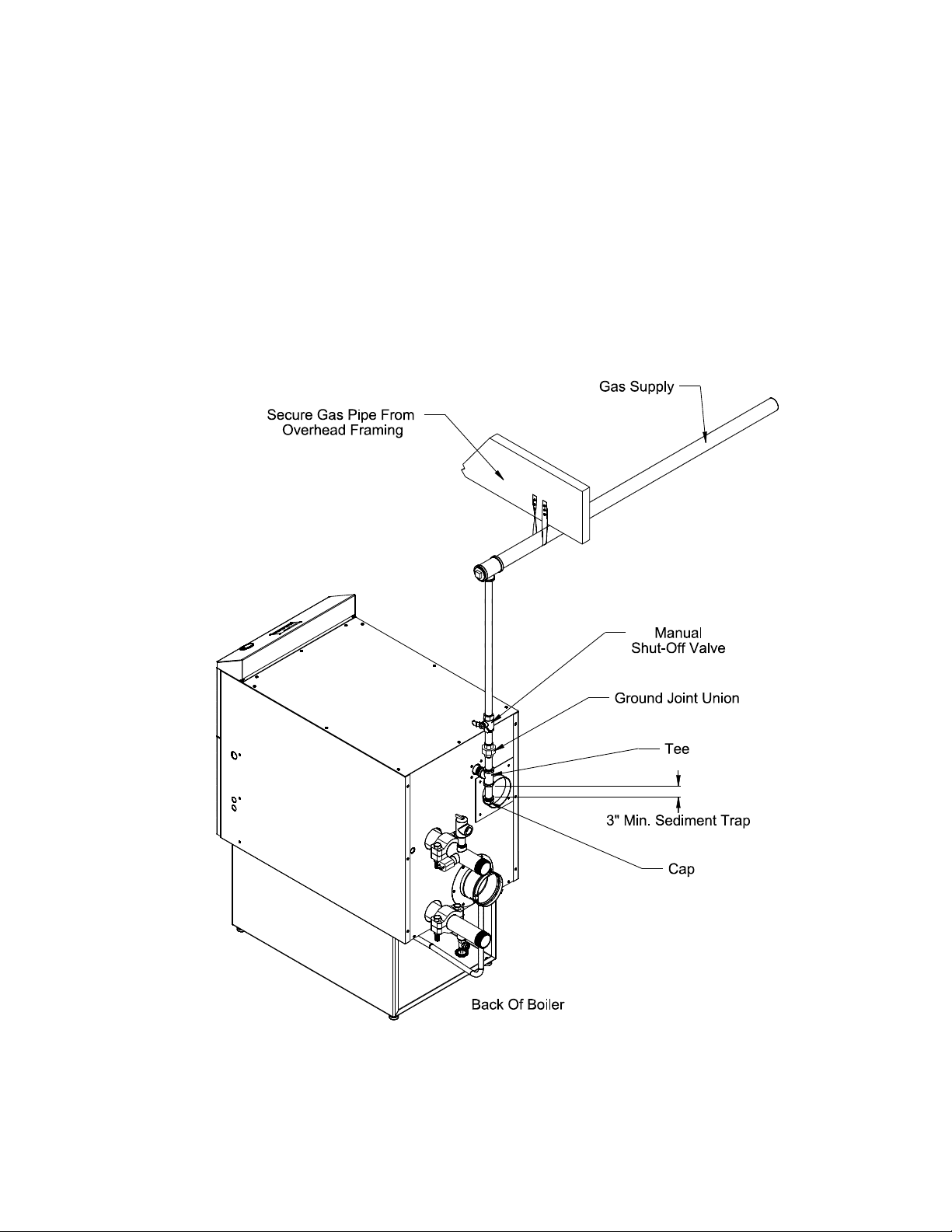
VII Gas Piping
Gas piping to the boiler must be sized to deliver adequate gas for the boiler to re at the nameplate input at an
inlet pressure between the minimum and maximum values shown on the rating plate. For more information on
gas line sizing, consult the utility or the National Fuel Gas Code.
Figure 7.1 shows typical gas piping connection to the TRIUMPH boiler. A sediment trap must be installed
upstream of all gas controls. Install the factory provided manual shut-off valve outside the jacket with a
ground joint union as shown.
The boiler and its gas connection must be leak tested before placing the boiler in operation. When doing this,
the boiler and its individual shut-off must be disconnected from the rest of the system during any pressure
testing of that system at pressures in excess of 1/2 psi. When pressure testing the gas system at pressures of
1/2 psi or less, isolate the boiler from the gas supply system by closing its individual manual shut-off valve.
Figure 7.1: Gas Connection To Boiler
33

VIII System Piping
A. General System Piping Precautions
WARNING
INSTALL BOILER SO THAT THE GAS IGNITION SYSTEM COMPONENTS ARE PROTECTED
FROM WATER (DRIPPING, SPRAYING, RAIN, ETC) DURING APPLIANCE OPERATION AND
SERVICE (CIRCULATOR REPLACEMENT, ETC).
CAUTION
THE HEAT EXCHANGER USED IN THE TRIUMPH IS MADE FROM A SPECIAL ALUMINUM ALLOY.
FAILURE TO TAKE THE FOLLOWING PRECAUTIONS COULD RESULT IN SEVERE BOILER
DAMAGE.
• BEFORE CONNECTING BOILER, MAKE SURE THAT THE SYSTEM IS FREE OF SEDIMENT,
FLUX AND ANY RESIDUAL BOILER WATER ADDITIVES. FLUSH THE SYSTEM IF
NECESSARY TO ENSURE THAT THESE CONTAMINATES ARE REMOVED.
• DO NOT CONNECT THIS BOILER TO A SYSTEM THAT IS SUBJECT TO REGULAR ADDITIONS
OF MAKEUP WATER OR ONE WHICH EMPLOYS RADIANT TUBING WITHOUT AN OXYGEN
BARRIER.
• DO NOT ADD ANTIFREEZE OR OTHER BOILER WATER TREATMENT CHEMICALS EXCEPT
THOSE LISTED IN PART X OF THIS MANUAL.
• MAINTAIN THE PRESSURE IN THE BOILER AT A MINIMUM OF 12 PSI.
• DESIGN SYSTEM TO ENSURE THAT THE FLOW FALLS WITHIN THE LIMITS CALLED FOR IN
TABLE 8.1.
• THE BOILER IS FURNISHED WITH 2” GROOVED COUPLINGS. IF THE RUBBER SEAL IN
THESE COUPLINGS MUST BE REPLACED, USE ONLY COMPATIBLE GRADE EDPM (GREEN
COLOR CODE) REPLACEMENTS.
B. System Design
Proper operation of the TRIUMPH boiler requires that the water ow through the boiler remain within the limits shown
in Table 8.1. Failure to maintain the ow within these limits could result in erratic operation or premature boiler failure.
There are two basic methods that can be used to pipe the TRIUMPH boiler. Method #1 is almost always preferred. The
instructions on the following pages describe these methods for piping TRIUMPH boilers and explain how to size the circulator
and piping. Additional information on hydronic system design may be found in Installation of Residential Hydronic Systems
(Pub. #200) published by the Hydronics Institute in Berkeley Heights, NJ.
TABLE 8.1: FLOW REQUIREMENTS THROUGH BOILER
BOILER MODEL
T300 15 30
T399 20 45
T425 21 45
MIN. REQUIRED FLOW AT
HIGH FIRE (GPM)
34
MAX. ALLOWABLE
FLOW (GPM)

Method 1: Primary/Secondary Piping
This method can be used in heat-only applications as shown in Figure 8.2 or with an indirect water heater as
shown in Figure 8.3. This method relies on primary/secondary pumping to ensure that the required ow is
always maintained through the boiler. In this system, the ow rate through the boiler is completely independent of
the ow rate through the heating system. Use the following guidelines to ensure that the boiler will have the required
ow shown in Table 8.1 regardless of the ow in the heating system.
1) Primary Loop Piping - Size the primary circulator and piping to obtain the design ow rate through the heating
system as you would on any other heating system. All piping between the expansion tank and secondary
connection tees must be at least as large as that shown in Table 8.5, column (a). In order to keep the ow rates in
the primary and secondary loops independent of each other, provide at least 8 diameters of straight pipe upstream
of the rst secondary tee and 4 diameters downstream of the second secondary tee. Keep the distance between the
expansion tank and the rst secondary tee as short as practical.
2) Secondary Loop (“Boiler Loop”) Piping – The secondary (or “boiler loop”) piping is shown shaded in gure 8.4a.
All piping in this loop must be the size shown for the boiler in Table 8.5, column (a). To size the circulator for this
loop:
a) Select one of the boiler water ow rates shown in Table 8.5, column (b) for the boiler and pipe size being
installed. When selecting the required boiler ow rate, keep in mind that if the ow rate in the primary loop
exceeds the ow rate through the boiler, it will not be possible to obtain a 180°F supply temperature in the
primary loop. This is because the supply water exiting the boiler will be mixed with cooler system return water
before entering the radiation.
b) Count all ttings in the planned secondary loop. In doing so, do not count the secondary connection tees, unions,
or the ttings supplied with the boiler (these have already been accounted for).
c) Using Table 8.6, nd the equivalent lengths of all ttings in the secondary loop. Total these equivalent lengths
and add them to the total length of planned straight pipe in the secondary loop. The result is the total equivalent
length of the secondary loop.
d) Refer back to the row in Table 8.5 from which the ow rate and pipe size were selected:
If the maximum equivalent length shown in column (e) is in excess of the total equivalent length •
calculated in Step (c) above, use the pipe size selected, along with the circulator shown in Table 8.5,
column (d).
If the maximum equivalent length shown in column (e) is in less than the total equivalent length calculated •
in Step (c) above, a larger pipe size and/or larger circulator is required. Select another circulator/pipe size
combination from Table 8.5 and repeat steps (b-d) above.
3) Indirect Water Heater Loop Piping (If Indirect Water Heater is Used) – The indirect water heater loop piping is
shown shaded in Figure 8.4b. Some of the piping in this loop is common to the secondary loop sized above. Piping
common to both loops is always sized from Table 8.5, column (a) as described above. All indirect water heater
loop piping that is not common (the “I.W.H branch”) is sized from Table 8.7, column (a). If the indirect water
heater connections are smaller than the pipe size called for in Table 8.7, column (a), reduce the pipe size at the
indirect water heater connections. To size the circulator:
a) Count all ttings in the planned Indirect Water Heater Loop (all shaded piping in Figure 8.4b). In doing so, you
will be counting some piping and ttings which are common to the heating system secondary (“boiler loop”)
piping and which were counted in Step 2a above. Do not count the ttings supplied with the boiler. If Table 8.7
requires a bypass, do not count the pipe and ttings in the by-pass.
b) Using Table 8.6, nd the equivalent lengths of all ttings in the indirect water heater loop. If the I.W.H. branch
pipe size is smaller than the secondary loop pipe size, calculate the equivalent lengths for all ttings (including
the larger size ttings common to both loops) based on the smaller size. Total these equivalent lengths and
add them to the total length of planned straight pipe (of both sizes) in the indirect water heater loop. The result
is the total equivalent length of the indirect water heater loop.
c) Refer back to the row in Table 8.7 from which the ow rate and I.W.H. branch pipe size were selected:
• If the maximum equivalent length shown in column (f) is in excess of the total equivalent length
calculated in Step (b) above, use the IWH branch pipe size selected, along with the circulator shown in
Table 8.7, column (e).
• If the maximum equivalent length shown in column (f) is in less than the total equivalent length
calculated in Step (b) above, a larger pipe size and/or larger circulator is required. Select another
circulator/pipe size combination from Table 8.7 and repeat steps (a-b) above.
35

Figure 8.2: Piping Method #1 - Heat Only
Example – Assume that a T300 is to be installed in a heating system along with an indirect water heater as shown in
Figure 8.3. A total of 15 ft of straight pipe will be installed between the boiler and the primary loop. A total of 25 ft of
straight pipe will be installed between the boiler and the indirect water heater. Of this 25 ft of straight piping, 10ft is
common to both the secondary and indirect water heater loop. This indirect water heater requires a ow rate of 8 GPM
and has a head loss of 3.0 ft. 20GPM is required through the secondary loop.
Total ttings in Secondary loop (“boiler loop”):
4 90 Elbows
2 Runs of Tees
1 Swing Check
2 Isolation Valves
Note: Unions, Secondary Connection Tees, and factory supplied ttings are ignored.
We would prefer to use 1-1/2” piping. Based on this, calculate total equivalent length from Table 8.6:
15ft Straight Pipe + 4 Elbows x 4.5 + 2 Runs of Tees x 2.8 + 1 Swing Check x 12.5 + 2 valves x 1.0 = 53.1
Equivalent Feet Straight Pipe. From Table 8.5, we see that a Taco 0012 will pump 20 GPM through a T300 with 89
equivalent feet of 1 1/2” pipe, so Taco 0012 will work in this application with 1 1/2” piping.
Total ttings in Indirect Water Heater Loop:
4 90 Elbows
2 Turns in Tees
1 Swing Check
2 Isolation Valves
All options shown in Table 8.7 for the indirect water heater show the use of 1” I.W.H branch piping. Although there is
10ft of piping common to both loops which is 1-1/2”, we calculate the equivalent length for the I.W.H. loop as though it
were entirely 1”. Therefore, the total equivalent length for the I.W.H. loop is calculated from Table 8.6 as:
25 Straight Pipe + 4 Elbows x 2.8 + 2 Turns in Tees x 5.5 + 1 Swing Check x 7 + 2 valves x 0.6 = 55.4 Equivalent
36

Figure 8.3: Piping Method #1 - Heat + Indirect Water Heater
Feet Straight Pipe. From Table 8.7, we see that a Taco 008 will pump at 8 GPM through a T300 with 56 equivalent
feet and an indirect water heater. The Taco 008 is just large enough to work in this application (a Taco 009 could
also be used if desired).
1” piping is used in the indirect water heater branch from the 1-1/2 x 1-1/2 x 1 Tees in the secondary loop all the way to
the coil connections on the indirect water heater.
4) Multiple Indirect Water Heaters - Pipe multiple indirect water heaters as shown in Figure 8.8. The use of reversereturn manifold ensures that the boiler water ow will be evenly divided between the two indirects. Table 8.7 shows
pump/piping sizing guidelines for up to two of Triad’s indirect water heaters. Measure the length of the I.W.H. loop to
the furthest indirect water heater. When guring the equivalent length, do not count the two Tees in the indirect water
heater manifold.
5) Indirect Water Heater By-pass - Some of the piping options shown in Table 8.7 require the use of a bypass around the
indirect water heater. This is done when the required boiler water ow through the indirect water heater is far lower than
the absolute minimum required ow through the boiler. The use of a bypass permits the use of a much smaller pump than
would otherwise be required. Refer to Figure 8.3 for the location of this bypass. The bypass pipe size should be the same
as the rest of the I.W.H. loop.
When the boiler is set-up, start with the throttling valve in the bypass fully open. Initiate a domestic hot water draw
and make sure that the boiler is operating at high re in response to a call for DHW. Then slowly close the bypass valve
until the temperature rise across the boiler is 40°F or less.
6) Maximum Input on Call for DHW - In most of the applications shown in Table 8.7, the boiler output required for the
indirect water heater is signicantly less than the maximum boiler output. This means that when the boiler is responding
to a call for DHW, the ow rate through the boiler can be smaller than is required when responding to a call for space
heating. As a result, smaller piping and circulators can often be used for the IWH loop. In order to take advantage of
this, however, it is necessary to limit the boiler’s ring rate when it is responding to a call for DHW. Table 8.9 shows the
maximum ring rate that is permissible at various boiler water ow rates. The input of this boiler is determined by the
fan speed. The maximum fan speed allowed when responding to a call for DHW is dened by parameters 15 and 16 in
the MCBA (See Appendix A for more information on settings and parameters). Both the ring rate and maximum DHW
fan speed are shown in Table 8.9 for various ow rates. Factory default maximum DHW fan speeds are shown in bold. In
most cases, it should not be necessary to change these parameters in the eld.
37

Figure 8.4a: Piping Method #1 - Secondary Loop Piping (Shaded)
Figure 8.4b: Piping Method #1 - Indirect Water Heater Loop Piping (Shaded)
38

TABLE 8.5: PIPE AND CIRCULATOR SIZING FOR BOILER LOOP
(a) (b) (c) (d) (e)
BOILER MODEL
T300 1-1/2 15.0 35 Taco 0010 124
T300 1-1/2 15.0 35 Taco 0012 234
T300 1-1/2 20.0 27 Taco 0012 89
T300 2 20.0 34 Taco 0012 455
T300 2 25.0 21 Taco 0012 116
T399 1-1/2 20.0 35 Taco 0012 128
T399 2 20.0 35 Taco 0012 618
T399 2 26.0 27 Taco 0012 199
T399 2-1/2 33.0 21 Taco 0012 108
T425 1-1/2 21.0 35 Taco 0012 111
T425 2 21.0 35 Taco 0012 512
T425 2 28.0 26 Taco 0012 147
T425 2-1/2 35.0 21 Taco 0012 50
PIPE SIZE FLOW
(in NPT) (GPM) (F) (ft)
TEMP
RISE
CIRCULATOR
MODEL
BOILER LOOP
MAX EQUIVALENT
LENGTH
TABLE 8.6: FITTING EQUIVALENT LENGTHS
FITTING PIPE SIZE
90 ELBOW 1 2.8 90 ELBOW 2 5.5
TURN IN TEE 1 5.5 TURN IN TEE 2 12.5
RUN OF TEE 1 1.8 RUN OF TEE 2 3.5
SWING CHECK 1 7.0 SWING CHECK 2 15.0
GATE VALVE 1 0.6 GATE VALVE 2 1.3
90 ELBOW 1-1/4 3.8 90 ELBOW 2-1/2 7.0
TURN IN TEE 1-1/4 8.0 TURN IN TEE 2-1/2 15.0
RUN OF TEE 1-1/4 2.5 RUN OF TEE 2-1/2 4.0
SWING CHECK 1-1/4 10.0 SWING CHECK 2-1/2 17.5
GATE VALVE 1-1/4 0.8 GATE VALVE 2-1/2 1.5
90 ELBOW 1-1/2 4.5
TURN IN TEE 1-1/2 10.0
RUN OF TEE 1-1/2 2.8
SWING CHECK 1-1/2 12.5
GATE VALVE 1-1/2 1.0
EQUIVALENT
LENGTH (ft)
FITTING PIPE SIZE
EQUIVALENT
LENGTH (ft)
39

TABLE 8.7: PIPE AND CIRCULATOR SIZING FOR INDIRECT WATER HEATER LOOP
INDIRECT WATER HEATER
REQUIREMENTS
(a) (b) (c) (e) (f) (g)
I.W.H.
BOILER
MODEL
T300 1 8.0 3.0 Taco 008 56 N
T300 1 8.0 3.0 Taco 009 112 N
T300 1 8.0 5.0 Taco 008 32 N
T300 1 8.0 5.0 Taco 009 87 N
T300 1-1/4 12.7 8.0 Taco 0014 72 N
T300 1-1/2 16.0 5.0 Taco 0014 73 N
T399
T425
T399
T425
T399
T425
T399
T425
T399
T425
BRANCH
PIPE
SIZE
(in NPT) (GPM)
1-1/4 8.0 3.0 Taco 0010 45 Y
1-1/4 8.0 3.0 Taco 0012 107 Y
1-1/4 8.0 5.0 Taco 0012 72 Y
1-1/4 12.7 8.0 Taco 0014 81 N
1-1/2 16.0 5 Taco 0014 113 N
I.W.H.
LOOP FLOW
NOT EXCEEDING
I.W.H.
PRESS. DROP
NOT EXCEEDING
(ft HEAD)
CIRC.
MODEL
I.W.H.
LOOP
MAX EQ.
LENGTH
(ft)
I.W.H.
BY-
PASS
REQ’D?
40

Figure 8.8: Piping Method #1 - Piping Multiple Indirect Water Heaters
TABLE 8.9: MAXIMUM ALLOWABLE D.H.W. FIRING RATE
(Inputs in Bold are Factory Settings)
MAX.
BOILER
MODEL
T300 8.0 8.0 N/A 168 3250 150
T300 12.7 12.7 N/A 262 5000 245
T300 15.0 15.0 N/A 300 5500 265
T399
T425
T399
T425
T399
T425
T399 20.0 20.0 N/A 399 4800 350
T425 22.0 22.0 N/A 425 5000 367
FLOW THROUGH BOILER DURING
CALL FOR D.H.W. (GPM)
BOILER I.W.H. I.W.H. BYPASS (MBH) (par. 15/16 - RPM) (MBH)
12.0 8.0 4.0 254 3000 236
12.7 12.7 N/A 272 3250 245
16 16 N/A 335 4000 310
ALLOWABLE
D.H.W. FIRING
RATE
MAX
ALLOWABLE
D.H.W. FAN
SPEED
BOILER
D.H.W.
OUTPUT
41

Method 2: Direct Connection to Heating System (Generally NOT Recommended)
The TRIUMPH can be connected directly to the heating system as is done with conventional boilers (Figure 8.10).
If this is done, the ow rate through the boiler will equal the ow rate through the system. The ow rate through the
system must therefore always remain within the limits shown in Table 8.1. For this reason, the pressure drop through
the entire system must be known, added to the boiler pressure drop, and a circulator selected which will provide the
required ow at the total calculated pressure drop.
This method is generally not recommended because it is often very difcult to accurately calculate the pressure
drop through the system. In replacement installations, it may be impossible to get an accurate measurement of the
amount of piping and number of ttings in the system. In addition, if the system is zoned, the system ow may drop
well below the minimum required when only one zone is calling for heat.
The one advantage to this method is its installation simplicity. It may make sense to use this method when the
boiler is to be installed with a new single zone system having a low-pressure drop. Pressure drop curves for the
TRIUMPH Series boilers are shown in Figure 8.11. Calculation of the system pressure drop, and selection of the
circulator, must be performed by someone having familiarity with pressure drop calculations, such as an HVAC
engineer.
Figure 8.10: Piping Method #2 - Direct Connection of Boiler to Heating System
42

T399 & 425
T300
0.00
2.00
4.00
6.00
8.00
10.00
0 10 20 30 40 50
Flow (GPM)
Head Loss (Feet w.c.)
Figure 8.11: Boiler Head Loss
C: Standard Piping Installation Requirements
Observe the following guidelines when making the actual installation of the boiler piping:
1) The relief valve, low water cut-off (LWCO), and boiler drain are mounted in special ttings that are attached
to the boiler supply and return connections using groove couplings as shown in Figure 2.1. The relief valve
and LWCO are mounted in the supply tting and the boiler drain is mounted in the return tting. In order to
avoid damage to these components, it is generally recommended that they be installed in the supply and return
ttings after the connections to the system are made.
2) Relief Valve - The factory-supplied relief valve is set to open at 30 psi. If the valve is replaced, the replacement
must have a relief capacity in excess of the minimum relief valve capacity shown on the rating plate. Pipe the
discharge of the relief valve to a location where water or steam will not create a hazard or cause property
damage if the valve opens. The end of the discharge pipe must terminate in an unthreaded pipe. If the relief
valve discharge is not piped to a drain, it must terminate at least 6 inches above the oor. Do not run relief valve
discharge piping through an area that is prone to freezing. The termination of the relief valve discharge piping
must be in an area where it is not likely to become plugged by debris.
DANGER
PIPE RELIEF VALVE DISCHARGE TO A SAFE LOCATION.
DO NOT INSTALL A VALVE IN THE RELIEF VALVE DISCHARGE LINE.
DO NOT INSTALL RELIEF VALVE IN A LOCATION OTHER THAN THAT SPECIFIED BY THE
FACTORY.
DO NOT PLUG THE RELIEF VALVE DISCHARGE.
43

3) Circulator (Required) - Usually at least two circulators will be required to properly install a TRIUMPH Series
boiler. See previous section (System Design) for information on sizing the circulators.
4) Expansion Tank (Required) - If this boiler is replacing an existing boiler with no other changes in the system, the
old expansion tank can generally be reused. If the expansion tank must be replaced, consult the expansion tank
manufacturer’s literature for proper sizing.
5) Fill Valve (Required) - Either a manual or automatic ll valve may be used. The ideal location for the ll is at the
expansion tank.
6) Automatic Air Vent (Required) - At least one automatic air vent is required. Manual vents will usually be required
in other parts of the system to remove air during initial ll.
7) Manual Reset High Limit (Required by some codes) - This control is required by ASME CSD-1 and some other
codes. Install the high limit in the boiler supply piping just above the boiler with no intervening valves. Set the
manual reset high limit to 200°F. Wire the limit per Figures 9.1 & 9.2 in the Wiring section.
8) Flow Control Valve (Required) - The ow control valve prevents ow through the system unless the circulator is
operating. Flow control valves are used to prevent gravity circulation or “ghost ows” in circulator zone systems
through zones that are not calling for heat.
9) Isolation Valves (Required) - Isolation valves are required to permit servicing of the boiler and groove couplings,
as they will eliminate having to drain and rell the entire system.
11) Drain Valve (Required) - The drain valve is installed in the return tting on the back of the boiler as shown in
Figure 2.1.
12) Low Water Cut-off (Required) - The low water cut-off supplied with this boiler must not be removed. It is installed
in the side of the supply tting as shown in Figure 2.1. Plug the harness protruding from the back of the boiler into
the low water cut-off.
D. Piping for Special Situations
1) Systems containing oxygen - Many hydronic systems contain enough dissolved oxygen to cause severe corrosion
damage to an aluminum boiler such as the TRIUMPH. Some examples include:
• Radiant systems that employ tubing without an oxygen barrier.
• Systems with routine additions of fresh water.
• Systems which are open to the atmosphere.
If the boiler is to be used in such a system, it must be separated from the oxygenated water being heated with a
heat exchanger as shown in Figure 8.12. Consult the heat exchanger manufacturer for proper heat exchanger sizing
as well as ow and temperature requirements. All components on the oxygenated side of the heat exchanger, such
as the pump and expansion tank, must be designed for use in oxygenated water.
2) Piping with a Chiller - If the boiler is used in conjunction with a chiller, pipe the boiler and chiller in parallel as
shown in Figure 8.13. Use isolation valves to prevent chilled water from entering the boiler.
3) Air Handlers - Where the boiler is connected to air handlers through which refrigerated air passes, use ow control
valves in the boiler piping or other automatic means to prevent gravity circulation during the cooling cycle.
4) Multiple Boiler Piping - Recommended piping for multiple TRIUMPH Series Boilers is shown in Figure 8.14.
Each boiler is piped into two closely spaced tees in a “cross-over bridge” connecting the supply and return sides of
the primary loop. The cross-over bridges are the same size as the primary loop piping and are piped in a reversereturn manner so that the ow through the primary loop is evenly divided among the bridges. At least 8 diameters
of straight pipe must be located upstream of the return tee in the bridge and at least 4 diameters of straight pipe
downstream of the supply tee in the bridge.
44

Figure 8.12: Isolation of the Boiler From Oxygenated Water with A Plate Heat Exchanger
Figure 8.13: Chiller Piping
45

46
Figure 8.14: Multiple Boiler Piping

IX Wiring
WARNING
All wiring and grounding must be done in accordance with the authority having jurisdiction or, in
the absence of such requirements, with the National Electrical Code (ANSI/NFPA 70).
1) Line Voltage (120 VAC) Connections (Fig 9.1) – The line voltage connections are located in the junction box
on the right side of the vestibule:
• Black – Line voltage “hot”
• White – “Neutral” for boiler and circulators
• Red – “Heating” circulator “hot”
• Blue – “Indirect Water Heater “ circulator “hot”
• Green – Ground connection
2) Maximum circulator continuous current draw is 2A. When Piping Method #1 is used, it may be desirable to
use the boiler to directly control the primary circulator in addition to the secondary circulator. If this is done,
control both heating circulators using a relay with a 120VAC coil, such as a Honeywell R4222, as shown in
Figure 9.3. Select a relay with a contact rating in excess of the combined draw of the two circulators.
3) Low Voltage Connections (Fig 9.1) – These connections are screw terminals located on the terminal strip next
to the junction box on the left:
• Terminals 1 and 2 – “Heating” thermostat connections
• Terminals 3 and 4 – “External Limit Control” connections
• Terminals 5 and 6 – “Outdoor Reset Sensor” connections
• Terminals 7 and 8 – “Domestic Indirect Water Heater” thermostat connections
• Terminal 9 – “Flame Signal Reading”
• Terminal 10 – “0-10 VDC (+)” external analog input signal
• Terminal 11 – “0-10 VDC (-)” external analog input signal
• Heat anticipator setting for the thermostat connection is 0.1 A when thermostat is connected directly to
terminals 1 and 2.
CAUTION
• WHEN MAKING LOW VOLTAGE CONNECTIONS, MAKE SURE THAT NO
EXTERNAL POWER SOURCE IS PRESENT IN THE THERMOSTAT OR LIMIT
CIRCUITS. IF SUCH A POWER SOURCE IS PRESENT, IT COULD DESTROY
THE BOILER’S MICROPROCESSOR CONTROL (MCBA). ONE EXAMPLE OF
AN EXTERNAL POWER SOURCE THAT COULD BE INADVERTENTLY CONNECTED TO THE LOW VOLTAGE CONNECTIONS IS A TRANSFORMER IN
OLD THERMOSTAT WIRING.
4) If the outdoor sensor is connected to terminals 5 and 6, the boiler will adjust the target space heating set point
supply water temperature downwards as the outdoor air temperature increases. If used, this sensor should be
located on the outside of the structure in an area where it will sense the average air temperature around the
house. Avoid placing this sensor in areas where it may be covered with ice or snow. In general, locations
where the sensor will pick up direct radiation from the sun should also be avoided. Avoid placing the sensor
near potential sources of electrical noise such as transformers, power lines, and uorescent lighting. Wire the
sensor to the boiler using 22 gauge or larger wire. As with the sensor, the sensor wiring should be routed away
from sources of electrical noise. Where it is impossible to avoid such noise sources, wire the sensor using a
2 conductor, UL Type CM, AWM Style 2092, 300Volt 60°C shielded cable. Connect one end of the shielding
on this cable to ground.
47

48
Figure 9.1: Wiring Connections Diagram

Figure 9.2: Ladder Diagram
49

Figure 9.3: Wiring of Isolation Relay for Control of Two Heating Circulators
5) A 0-10 VDC external analog control signal installed across terminals 10 and 11 can be used to either adjust the
boiler water setpoint or to control the ring rate. Refer to the 0-10VDC control manufacturer’s instructions for the
size and type of wire to use for the 0-10VDC connections between the external control and the boiler. In general,
it is a good idea to route this wiring away from potential sources of electrical noise, such as transformers, power
lines, and uorescent lighting. Where such sources cannot be avoided, it may be necessary to use properly grounded
shielded cable.
The MCBA (boiler control) must be reprogrammed in order to accept the 0-10VDC signal. Refer to Appendix A for
information on how to do this.
50

X Start-up and Checkout
NOTE
SAFE LIGHTING AND OTHER PERFORMANCE CRITERIA WERE MET WITH THE GAS TRAIN
ASSEMBLY PROVIDED ON THE BOILER WHEN THE BOILER UNDERWENT THE TEST
SPECIFIED IN Z21.13.
Use the following procedure for initial start-up of the boiler:
1) If not already done, ush the system to remove sediment, ux, and traces of boiler additives. This should be
done with the boiler isolated from the system.
2) Fill the boiler and hydronic system with water meeting the following requirements:
pH between 6.5 and 8.5
Total Solids less than 2500 PPM
Hardness less than 120 PPM (7 Grains/Gallon)
Pressurize the system to at least 12 psi at the boiler
WARNING
• NEVER ATTEMPT TO FILL A HOT EMPTY BOILER.
3) Check all new piping for leaks and purge piping sections that are lled with air. See the National Fuel Gas
Code for additional information on testing and purging gas lines.
WARNING
• NEVER USE A FLAME TO CHECK FOR GAS LEAKS.
• MAKE SURE THAT THE AREA AROUND THE BOILER IS CLEAR AND FREE FROM
COMBUSTIBLE MATERIALS, GASOLINE AND OTHER FLAMMABLE VAPORS AND
LIQUIDS
4) Vent system must be complete and free of obstructions before attempting to re boiler. Make sure that the
silicone cure time called for in the vent assembly instructions has passed before ring boiler.
5) Inspect all line voltage wiring for loose or uninsulated connections.
6) Remove the dust cap from the condensate trap (Fig 6.11). Add water to the trap until water runs out the con-
densate drain. Reinstall the dust cap.
51

WATER QUALITY AND BOILER WATER ADDITIVES
IMPORTANT NOTE
This boiler is equipped with an aluminum heat exchanger that can be seriously damaged by failure to
follow the following guidelines:
1) Flush the system before connecting the boiler - In a replacement installation, ushing the system will
remove sediment, solder ux, and traces of old boiler additives. Even if the system is new, do not omit this
step - new systems will contain solder ux and may even contain sediment.
2) Make sure that the system is tight - This is the single most important guideline. Tap water contains
dissolved oxygen which causes corrosion. In a tight system, this oxygen comes out of solution and is
quickly removed from the system through the automatic air vent. The system then remains essentially free
of oxygen. If the system is not tight, however, frequent additions of make-up water can expose the heat
exchanger to oxygen on a continuous basis. In addition, frequent additions of hard make-up water can
cause calcium deposits to collect in the heat exchanger, causing severe damage.
To minimize additions of make-up water:
• Inspect the system thoroughly for leaks before placing it in service.
• If the system includes underground piping, or other piping in which a leak might go undetected,
consider isolating the boiler from the system with a heat exchanger. Alternatively, consider
installing a water meter in the ll line to record additions of make-up water.
• Make sure that the expansion tank is properly sized and in good condition. If it is not, the relief
valve may open frequently, resulting in regular additions of make-up water.
3) Radiant Tubing and Oxygen Barriers - Even if the system is tight, oxygen can be introduced into the
system through some types of non-metallic tubing used in radiant or snow melt systems. Other non-
metallic tubing is equipped with an oxygen barrier to prevent migration of oxygen into the water. If the
boiler is to be installed in a system containing non-metallic tubing without an oxygen barrier, it must be
isolated from the boiler with a heat exchanger as shown in Figure 8.12.
4) Antifreeze - Do not use antifreeze unless absolutely necessary. If antifreeze must be used, the only
permitted antifreezes are:
• Fernox Alphi-11
• RhoGard Aluminum Safe Multi-Metal Antifreeze
If either of the above antifreezes are used, test the boiler water on an annual basis to ensure that the
antifreeze remains non-corrosive. This is done with Fernox test kit I-TK (available from Triad).
5) Other Antifreezes and Boiler Additives - Do not add other additives unless they are specically
approved in writing by Triad for use with this boiler. This includes other “aluminum safe” antifreezes.
6) System pH - Maintain the pH in the system between 6.5 and 8.5.
52

A.
•
C.
B.
D.
•
•
•
1. 6.
2. 7.
3.
4. 8.
9.
5. 10.
11.
12.
1. 3.
2. 4.
FOR YOUR SAFETY READ BEFORE LIGHTING
This appliance does not have a pilot. It is
equipped with an ignition device which
automatically lights the burner. Do not
try
to light the burner by hand.
Do not touch any electric switch; do
not use any phone in your building.
If you cannot reach your gas supplier, call the
fire department.
WHAT TO DO IF YOU SMELL GAS
Do not try to light any appliance.
WARNING: If you do not follow these instructions exactly, a fire or explosion may
result causing property damage, personal injury or loss of life.
Immediately call your gas supplier
from a neighbor's phone. Follow the
gas supplier's instructions.
Use only your hand to turn the gas control knob.
Never use tools. If the knob will not push in or turn by
hand, don't try to repair it, call a qualified service
technician. Force or attempted repair may result in a
fire or explosion.
Do not use this appliance if any part has been under
water. Immediately call a qualified service technician
to inspect the appliance and to replace any part of the
control system and any gas control which has been
under water.
OPERATING INSTRUCTIONS
BEFORE OPERATING smell all around the
appliance area for gas. Be sure to smell
next to the floor because some gas is
heavier than air and will settle on the floor.
STOP! Read the safety information above on
this label.
Set the thermostat to the lowest setting.
Turn off all electric power to the appliance.
This appliance is equipped with an ignition
device which automatically lights the burner.
Do not
try to light the burner by hand.
Remove the front door panel and the upper
boiler access panel.
Replace the upper boiler access panel and the front
door panel.
TO TURN OFF GAS TO THE APPLIANCE
Smell for gas in the boiler enclosure. If you smell gas,
STOP! Follow "B" in the safety information above. If
you don't smell gas, go to the next step.
Turn on all electric power to the appliance.
Set the thermostat to the desired setting.
The first digit of the control display panel will
show a series of numbers that indicate the boiler
control sequence. The number 3 or 4 means the
burner is firing. The number 0 means there is no
call for heat from the thermostat or the domestic
water heater.
Turn off all electric power to the appliance if
service is to be performed.
Set the thermostat to the lowest setting.
Turn the external boiler manual gas valve Thandle counterclockwise to open gas supply.
ඞ
Turn the external boiler manual gas valve Thandle clockwise to close the gas supply.
ඟ
Replace the upper boiler access panel and the front
door panel.
If the appliance will not operate, follow the
instructions "To Turn Off Gas To Appliance" below
and call your service technician or gas supplier.
Triumph Series Lighting and Operating Instructions
53

7) Start the boiler using the lighting instructions on page 53. After the boiler is powered up, it should go through
the following sequence.
Sequence Display Meaning
1 U.126 or Blank Checking internal software (power-up only)
2 0.SWT Boiler in standby. SWT = Supply Water Temp. No call for heat.
(After call for heat from heating thermostat)
3
4 5.SWT Blower and circulator on. Checking for adequate air ow.
5 1.SWT Prepurge
6 2.SWT Trial for ignition
7
8) Upon initial start-up, the gas train will be lled with air. Even if the gas line has been completely purged of air,
it may take several tries for ignition before a ame is established. The maximum number of tries are as
follows:
• T300 - 5
• T399/425 - 2
If more tries for ignition are needed, it will be necessary to press the reset button to restart the boiler. Once a
ame has been established for the rst time, subsequent calls for burner operation should result in a ame on
the rst try.
A.SWT Self-Check on Start-up
3.SWT Flame established. Boiler responding to a call for heat.
9) Inspect the ame visible through the window. On high re the ame should be stable and mostly blue
(Fig.10.1). No yellow tipping should be present; however, intermittent ecks of yellow and orange in the ame
are normal.
Figure 10.1: Triumph Burner
10) Check the inlet pressure and adjust if necessary. Verify that the inlet pressure is between the upper and lower
limits shown on the rating plate with all gas appliances on and off.
WARNING
THE CORRECT OUTLET PRESSURE FOR THE GAS VALVE HAS BEEN FACTORY SET
AND REQUIRES NO FIELD ADJUSTMENT. THIS SETTING IS SATISFACTORY FOR
BOTH NATURAL GAS AND PROPANE. ATTEMPTING TO ADJUST THE OUTLET PRESSURE MAY RESULT IN DAMAGE TO THE GAS VALVE AND CAUSE PROPERTY DAMAGE, PERSONAL INJURY OR LOSS OF LIFE.
54

Figure 10.2: Dungs Gas Valve Detail
11) Perform a combustion test. The ue gas sample may be drawn from any of the following points:
a) All stainless steel vent adaptors are equipped with a combustion test port
b) The optional concentric vent adaptor used with the T300 has no test port, but a sample can be drawn
from the condensate drain connection on the bottom of the adaptor. If this is done, disconnect the plastic
tubing from the bottom of the adaptor and temporarily plug it.
c) A sample can be drawn by inserting the combustion analyzer probe into the vent terminal.
There is also a sample port under the control console from which the combustion air in the cabinet can be
sampled (this is useful if ue gas recirculation if suspected). If this port is used, be sure to replace the rubber
plug when the test is completed.
Check CO2 (or O2) and CO at both high and low re. The boiler may be temporarily locked into high or low
re for 15 minutes as follows:
a) To lock the boiler in high re, simultaneously press and hold the “Mode” button and “+“ button until
the display ashes “H”, indicating that the boiler has been driven to high re. After this happens,
allow the boiler to operate for approximately 5 minutes before taking combustion readings.
b) To lock the boiler in low re, simultaneously press and hold the “Mode” button and “-“ button until
the display ashes “L”, indicating that the boiler has been driven to low re. After this happens, allow
the boiler to operate for approximately 5 minutes before taking combustion readings.
At both high and low re, CO readings should be less than 75 PPM. Typical CO2 readings are shown in Table
10.3. Normal modulation should return 15 minutes after the boiler is locked in high or low re.
12) Test any external limits or other controls in accordance with the manufacturer’s instructions.
13) Verify that the boiler starts and stops in response to calls for heat from the heating thermostat and indirect
water heater thermostat. Make sure that the appropriate circulators also start and stop in response to the ther mostats.
55

Table 10.3: Typical Sea Level CO2/O2 Combustion
Model Fuel %CO2 %O2
T300 (Dungs Valve) Natural Gas 9.0 5.1
T399 (Dungs Valve) Natural Gas 9.0 5.1
T425 (Dungs Valve) Natural Gas 9.0 5.1
T300 (Dungs Valve) Propane 10.2 5.4
T399 (Dungs Valve) Propane 10.2 5.4
T425 (Dungs Valve) Propane 10.2 5.4
WARNING
EACH TRIUMPH SERIES BOILER IS TESTED AT THE FACTORY AND ADJUSTMENTS
TO THE AIR-FUEL MIXTURE ARE NORMALLY NOT NECESSARY. CONSULT A TRIAD
REPRESENTATIVE BEFORE ATTEMPTING TO MAKE ANY SUCH ADJUSTMENTS.
IMPROPER GAS VALVE OR MIXTURE ADJUSTMENTS COULD RESULT IN PROPERTY
DAMAGE, PERSONAL INJURY, OR LOSS OF LIFE.
56

XI Operation
1) The TRIUMPH boiler uses a microprocessor based control, known as a “MCBA”, to manage all boiler functions
including ame supervision and modulation. Two set point or “target” boiler supply temperatures are stored
in the MCBA’s memory; one for space heating and one for domestic water production. If an outdoor tempera-
ture sensor is connected to the boiler, the space heating supply set point will automatically adjust downwards
as the outdoor temperature increases. For more information on this feature see the discussion on boiler water
reset below.
The MCBA modulates the boiler input by varying the fan speed. As the fan speed increases, so does the
amount of gas drawn into the blower. As a result, a fairly constant air-fuel ratio is maintained across all inputs.
The MCBA determines the input needed by looking at both current and recent differences between the supply
temperature and the set point temperature. As the supply temperature approaches the set point temperature, the
fan will slow down and the input drop.
The MCBA also monitors boiler return and ue temperatures. In addition, all other safety controls, including
the low water cut-off and safety limit, are connected into the MCBA. The MCBA uses input from all of these
controls to either shut down the boiler when an unsafe condition exists or, in some cases, to correct the
problem.
2) The display panel has three primary modes of operation. These are:
• Standby Mode – Displays boiler’s current status. This is the default operating mode.
• Parameter Mode – Used to change control settings
• Information Mode – Displays boiler operating temperatures
Under normal conditions, the boiler is in standby mode and the display looks like that shown in Figure 11.1.
The three digits to the right of the decimal point are the boiler’s supply temperature. The digit to the left of the
decimal point is the boiler’s status code. A list of status codes, and their meanings, is shown in Table 11.3.
Figure 11.2 is a map of the menu structure for the control panel. Push the mode key to move from one mode to
the next. As you change modes, the mode you are entering is shown on the display:
a) “PArA” for Parameter Mode
b) “Info” for Information Mode
c) “Stby” for Standby Mode. Upon entering standby mode, “Stby” will briey appear on the display
and then the display will show the boiler’s status along with the supply temperature (Figure 11.1).
The control will return to standby mode from any other mode if no key is pressed for 20 minutes.
Figure 11.1: Normal Display In Standby Mode
57

In standby mode, it is possible to view both the heating supply set point temperature and the “domestic hot water
reference set point”. The “domestic hot water reference set point” plus 45°F equals the boiler supply set point when
it is responding to a call from the indirect water zone. It is not the actual domestic hot water set point. The TRIUMPH
is designed for use with a storage type indirect water heater. The domestic water set point is controlled by the ther mostat on the indirect water heater. The “default domestic water reference set point” is 135°F and target boiler sup ply temperature when responding to a call from the indirect water heater is therefore 180°F (135°F +45°F). The
default heating supply set point (parameter 4) is 180°F.
In standby mode it is also possible to turn on or off either the heating or domestic water zone. There is normally no
reason to turn off either of these zones and doing so is not recommended.
CAUTION
PUSHING AND HOLDING THE “+” WHILE IN STANDBY MODE WILL PREVENT THE BOILER
FROM RESPONDING TO A CALL FOR HEAT. PUSHING AND HOLDING THE “-” WHILE IN
STANDBY MODE WILL PREVENT THE BOILER FROM RESPONDING TO A CALL FOR DOMESTIC WATER. IF THIS HAPPENS, “cOFF” or “dOFF” WILL APPEAR ON THE DISPLAY. TO TURN
BACK ON THE HEATING FUNCTION, PRESS AND HOLD “+” UNTIL “c” AND THE SET POINT
TEMPERATURE APPEARS ON THE DISPLAY. TO TURN BACK ON THE DOMESTIC WATER FUNCTION, PRESS AND HOLD “-” UNTIL “d” AND THE SET POINT TEMPERATURE APPEARS ON THE
DISPLAY. AFTER PRESSING ANY KEYS, AND BEFORE LEAVING THE INSTALLATION, VERIFY
THAT THE BOILER FIRES IN RESPONSE TO A CALL FOR HEAT AND DOMESTIC WATER.
In standby mode, if “Mode” and either “+” or “-“are simultaneously pushed and held for at least 2 seconds, the
burner can be forced into either high or low re. This feature is used for running combustion tests. After 15 minutes,
the burner will automatically revert to modulation. If it is desired to revert to modulation before 15 minutes has
passed, simultaneously pushing “+” and “-“ will restore modulation.
In Parameter mode both set points can be changed and both zones turned on or off. In addition, both zones can be
congured for continuous pump operation. If the heating zone is set for continuous pump operation (parameter 3 set
to 3), the heating pump will still shut down when there is a call for domestic hot water.
If either the heating supply set point (parameter 4) , or the DHW reference set point (parameter 1) are set above
their factory set values, the boiler supply temperature will exceed 180°F and there is a possibility that the safety
temperature limit will open. If this happens, the boiler will shut down and a “b26” error will appear on the display.
The boiler will resume normal operation without manual intervention when the safety limit closes (this behavior is
common on conventional boilers).
Information mode is used to view various temperatures and settings but cannot be used to change parameters or
otherwise control the boiler. The information available is shown in Figure 11.2 and is largely self-explanatory. The
digit to the left of the decimal point is the Step number and the digits to the right are the corresponding temperature.
In information mode, the “supply water temperature set point” (Step 6), is the supply temperature set point for the
zone to which the boiler is currently responding (either heat or DHW). If an outdoor sensor is connected to the
boiler, and the boiler is responding to a call for heat, this value will be the current point on the reset curve. When no
call for heat or DHW is present, Step 6 shows the heating supply set point.
In some cases a “-22” will appear in Information Mode for a particular reading. This means that the reading is not
applicable. For example, “-22” will appear for the outdoor temperature (Step 4) if no outdoor sensor is connected to
the boiler.
58

FIGURE 11.2: BASIC MENU TREE
USE MODE KEY TO TOGGLE BETWEEN MODES
(Mode returns to Standby from other modes if no key is pressed for 20 min.)
STANDBY MODE PARAMETER MODE INFORMATION MODE
Use of
Keys
Duration Result
Display
Example
Parameter Description
Possible Settings
(Note 4)
Use of Keys
Step # Value
Display
Example
Use of Keys
STEP + - STORE STEP + - STORE
+ Short
Shows supply set point
when responding to call
for heat (Note 1)
c 190
1
DHW reference set
point (Note 2)
68°F - 144°F (Default
Setting 135°F)
Toggle Between Parameters
Increases Setting
Decreases Setting
Saves new setting to MCBA. Display will Flash when STORE is released indicating that
change has been made
1 Supply water temperature
1.170
Toggle Between Steps 1 - A
Not Used
Not Used
Not Used
+ Long Turn heating on/off
c OFF
2 DHW Zone
0 = Off 2 Return water temperature
2.135
- Short
Shows domestic hot water
reference set point (Note
2)
d 144
1 = On 3 Reserved for Future Use
3.-22
- Long
Turn domestic hot water
on/off
d OFF
2 = Off + continuous
pump
4
Outdoor sensor temp., if
used (Note 5)
4.-22
MODE
and +
Long
Hold burner in high fire
(Note 3)
H 180
3 = On + continuous
pump
5 Flue gas temperature
5.165
MODE
and -
Long
Hold burner in low fire
(Note 3)
L 180
3 Heat Zone
0 = Off 6
Supply water set point
temperature
6.180
+ and - Long
Deactivate forced high or
low firing
O 180
1 = On
7
Rate of change in supply
water temperature °F/sec
7. 0 1
2 = Off + continuous
pump
3 = On + continuous
pump
8
Rate of change in return
water temperature °F/sec
8. 0 1
4
Supply set point
when responding to
call for heat
68°F - 190°F (Default
Setting 180°F)
9 Reserved for Future Use
9. 0 1
A Reserved for Future Use
A. -22
Notes
1) If outdoor sensor is connected, this temperature is the supply temperature setpoint when the outdoor temperature is 0°F.
2) "Domestic water reference set point" + 45°F = boiler supply set point when boiler is responding to a call for domestic hot water (default = 180°F).
3) Boiler will automatically resume modulation after 15 minutes.
4) Factory default settings are shown in bold.
5) If no outdoor sensor is connected, display reads "4.-22".
59

3) Two basic types of errors codes are shown on the display:
• Soft Lockout Codes – When a soft lockout occurs, the boiler will shut down and the display will alter nate between the number “9” and the letter “b” followed by a two digit service code. A list of these
codes, and their meanings, is shown in Table 11.3. The boiler will automatically restart once the condi tion that caused the lockout is corrected.
• Hard Lockout Codes – When a hard lockout occurs, the boiler will shut down and the display will
ash the letter “E” followed by a two digit service code. A list of these codes, and their meanings, is
shown in Table 11.3. Once the condition that caused the lockout is corrected, the boiler will need to be
First Digit Boiler Status
0 Burner off - No call for heat or DHW
1 Pre-purge or post-purge
2 Ignition
3 Burner responding to call for heat
4 Burner responding to call for DHW
5 Checking air pressure switch
6 Burner off - Set point temperature has been reached
7 Call for heat ended. 10s heating post pump period
8 Call for DHW ended. 10s DHW post pump period
9 and b
Flashing
A Boiler responding to call from heating zone
H Burneron-Heldinhighre
L Burneron-Heldinlowre
Burner off - on soft lockout. See Troubleshooting
Section to determine meaning of error code.
Table 11.3: Boiler Status
4) If an outdoor sensor is installed, the boiler will automatically adjust the heating zone set point temperature
based on the outdoor reset curve in Figure 11.4. The maximum set point is dened by parameter 4 (factory set
to 180°F) when the outdoor temperature is 0°F or below. The minimum set point temperature shown is 130°F
when the outdoor temperature is also 60°F or above. As the outdoor temperature falls, the supply water target
temperature increases. For example, if the outdoor air temperature is 30°F, the set point temperature for the
supply water is 155°F.
5) An indirect water heater thermostat can be connected between terminals 7 and 8 on the terminal strip. When
this thermostat closes, the central heating circulator will be turned off and the DHW circulator will be turned
on.
6) An external limit control can be installed between terminals 3 and 4 on the terminal strip. Be sure to remove
the jumper between terminals 3 and 4 when adding an external limit control to the system. If the external limit
opens, the boiler will shut down and error code “b 26” will be displayed. If the limit installed is a manual
reset type, it will need to be reset before the boiler will operate.
60

Figure 11.4: Outdoor Reset Curve
7) The sequence of operation for a TRIUMPH series boiler on a call for heat from a thermostat is as described below:
a) When power is rst turned on, 120V is provided to the MCBA, the combustion fan and the LWCO trans-
former. A separate 50VA transformer, connected directly to the MCBA, powers all other low voltage circuits.
b) For the rst few seconds after power-up the control module goes through a self check.
c) When there is a call for heat, the control module checks to make sure the air pressure switch is open. If it is, the
combustion fan will be energized and will ramp up to ignition speed. When the air pressure switch closes, a 10
second prepurge is activated.
d) After the prepurge, the control module energizes the gas control valve and the spark for 3 seconds. If a
ame is established and proved, the control allows the ame to stabilize for 5 seconds at the combustion fan
ignition speed setting. If the ame fails to prove, the control module will attempt to light the burner 4 more
times. If a ame is still not established, the control will lockout.
e) Once the ame stabilization period has ended, the MCBA allows the burner to modulate. The actual ring rate
is dependent upon the measured current and recent differences between the set point temperature and the supply
temperature. If an outdoor sensor is connected to the control module and the boiler is responding to a call for
heat, the set point temperature will be determined by the outdoor reset curve shown in Figure 11.4.
f) Once the set point temperature is reached, the MCBA will turn the burner off.
g) The central heating pump will continue to operate until the room thermostat has been satised.
h) A demand for domestic hot water (DHW) is given priority on TRIUMPH series boilers. If a call for DHW is
received while the boiler is responding to a call for heat, the heating circulator is deenergized until the call for
DHW is satised.
61

XII. Service and Maintenance
IMPORTANT
WARRANTY DOES NOT COVER BOILER DAMAGE OR MALFUNCTION IF THE FOLLOWING STEPS ARE NOT PERFORMED AT THE INTERVALS SPECIFIED
1) Continuously:
a. Keep the area around the boiler free from combustible materials, gasoline and other
ammable vapors and liquids.
b. Keep the area around the combustion air inlet terminal free from contaminates .
c. Keep the boiler room ventilation openings open and unobstructed.
2) Monthly Inspections:
a. Inspect the vent piping and outside air intake piping to verify they are open, unobstructed and free
from leakage or deterioration. Call the service technician to make repairs if needed.
b. Inspect the condensate drain system to verify it is leak tight, open and unobstructed. Call the service
technician if the condensate drain system requires maintenance.
c. Inspect the water and gas lines to verify they are free from leaks. Call the service technician to make
repairs if required.
CAUTION
4) Annual Inspections and Service: In addition to the inspections listed above the following should be per-
formed by a service technician once every year.
a. Test the low water cutoff by pressing the “Test” button located at its end. The yellow light should
come on and “E12” should ash on the display. Push the reset button on the display to restore normal
operation. If the yellow light does not come on, determine why the low water cutoff is not working
properly.
b. Follow the procedure for turning the boiler off found in the TRIUMPH Series Lighting and Operating
Instructions.
c. Inspect the wiring to verify the conductors are in good condition and attached securely.
WATER LEAKS CAN CAUSE SEVERE CORROSION DAMAGE TO THE BOILER OR
OTHER SYSTEM COMPONENTS. IMMEDIATELY REPAIR ANY LEAKS FOUND.
CAUTION
LABEL ALL WIRES PRIOR TO DISCONNECTION WHEN SERVICING CONTROLS.
WIRING ERRORS CAN CAUSE IMPROPER AND DANGEROUS OPERATION. VERIFY
PROPER OPERATION AFTER SERVICING.
62

d. Remove the ignition electrode and inspect it for oxides. Clean the oxides off the electrode with
steel wool. Inspect the ceramic insulator for cracks and replace the ignitor assembly as necessary.
e. Remove the combustion fan/gas valve assembly and inspect the fan and fan blade for lint and dust.
Vacuum as required.
f. Remove the burner hood to access the burner and the chamber.
g. Remove the burner and vacuum any dust or lint from the burner. Wipe the inside of the burner
with a clean soft cloth. Do not wipe the mesh side of the burner. If the burner shows signs of
deterioration or corrosion, replace it immediately. Inspect the burner gasket and replace, if necessary.
h. With the burner removed, inspect the combustion chamber and clean as necessary.
i. Inspect the heat exchanger and vacuum any debris found on the pins and other surfaces. Clean
the casting pins by ushing with clean water. A soft nylon brush may be used in accessible areas.
Drain and ush the inside of the heat exchanger and condensate collector as required. Do not use any
cleaning agents or solvents.
j. Inspect the condensate trap to verify it is open and free from debris. Clean if necessary.
k. Reinstall the burner, burner hood, combustion fan and gas valve assembly.
l. Reconnect any wiring which has been disconnected.
m. Qualied service personnel should thoroughly inspect the heating system and correct any deciencies
prior to restarting the boiler.
n. Follow Section X Start-up and Checkout instructions before leaving installation.
o. Perform the combustion test outlined in Section X.
p. Verify that the system pH is between 6.5 and 8.5
63

XIII. Troubleshooting
WARNING
TURN OFF POWER TO BOILER BEFORE REPLACING FUSES OR WORKING ON WIRING.
A. Troubleshooting problems where no error code is displayed:
Table 13.1: No Error Code Displayed
CONDITION POSSIBLE CAUSES
Display Blank, Fan off, LWCO lights off
Display Panel Blank, Fan running
Displayreads“U.125”continuously,Fanrunning
Boiler not responding to call for heat, Status code on display
=”0”(seeFigure11.1)
Boilerres,butdisplaypanelisblank
•No120VACPoweratboiler.Checkbreakerandwiring
between breaker panel and boiler
•Loose120VACconnectionwiringbetweenboilerJ-Boxand
MCBA
•Blown“F1”fuseinMCBA(seeFigure13.2forlocation).
Replace with 5A fuse provided
•DefectiveAT250transformer
•Blown“F3”fuseinMCBA(seeFigure13.2forlocation).
Replace with 4A slow-blow fuse provided
•Boilerisnotseeingcallforheat.Checkthermostator
zone wiring for loose connection, miswiring, or defective
thermostat/zone control.
•Looseribboncable
•Defectivedisplay
Figure 13.2: MBCA Fuse Location
64

B. Trouble shooting problems where a soft lockout code is displayed. When a soft lockout occurs, the boiler will
shut down and the display will alternate between the number “9” and the letter “b” followed by a two digit
service code. The boiler will automatically restart once the condition that caused the lockout is corrected.
Table 13.3: Soft Lockout Codes Displayed
CODE CONDITION POSSIBLE CAUSES
•Blockageinintakeorventsystem.
•Ventand/orintakesystemnotconstructedinaccordance
b 08 Pressure switch circuit open
b 18
MCBA supply sensor detected temperatures in excess
of 200°F
with Part VI.
•Blockedorleakingpressureswitchtubing
•Heatexchangerorburnerblockage
•Terminalsexposedtohighwinds
•Blockageincondensatetrapabovevent.
•Heatingloadattimeoferrorwasfarbelowtheminimum
ringrateoftheboiler
•Defectiveprimarypumpornoowinprimaryloop(Piping
Method 1)
•Controlsystemmiswiredsothatboileroperationis
permitted when no zones are calling
b 19
b 24
b 25 Supply water temperature has risen too quickly
b 26
b 30 Temperature rise between supply and return is too high.
b 61 Pressure switch circuit closed with fan off
b 65 Fan is not achieving set point speed
MCBA return sensor detected temperatures in excess of
200°F
MCBA is reading a return sensor temperature higher
than the supply sensor temperature. Condition must be
present for at least 75s for this error code to appear.
Boiler safety limit, or external limit wired across terminals
3&4, is open.
•Seepossiblecausesfor“b18”
•Flowthroughboilerreversed
•Sensorwiringreversed
•Flowthroughboilerreversed.Verifycorrectpipingand
pump orientation.
•Noboilerwaterow.Verifythatsystemispurgedofair
and that appropriate valves are open.
•Sensorwiringreversed.
•Supplyorreturnsensordefective.
•Seepossiblecausesfor“b18”
•Inadequateboilerwaterow.Verifythatpumpis
operating and that pump and piping are sized per Part
VIII of this manual
•Seepossiblecausesfor“b18”
•Defectivesupplysensor.
•Inadequateboilerwaterow.Verifythatpumpis
operating and that pump and piping are sized per Part
VIII of this manual
•Blockageinpressureswitchhose
•Pressureswitchwiresshortedtogether
•Defectivepressureswitch
•Looseormiswiredfanspeedharness(if“b61”errorcode
is observed while fan is running)
•Looseorincorrectfanspeedcontrolconnection
•Defectivefan
65

C. Trouble shooting problems where a hard lockout code is displayed. When a hard lockout occurs, the boiler
will shut down and the display will ash the letter “E” followed by a two digit service code. Once the condition
that caused the lockout is corrected, the boiler will need to be manually reset using the RESET button on the
display.
Table 13.4: Hard Lockout Codes Displayed
CODE CONDITION POSSIBLE CAUSES
E 00
E 02
Aamesignalwaspresentwhenthereshould
benoame.
T300: Flame failure after 5 tries to restart
T399/425: Flame failure after 2 tries to restart
•Defectivegasvalve-makesureinletpressureisbelowmaximum
on rating plate before replacing valve.
•Nogaspressure
•Gaspressureunderminimumvalueshownonratingplate
•Gaslinenotcompletelypurgedofair
•DefectiveElectrode
•Looseburnergroundconnection
•DefectiveIgnitionCable
•Defectivegasvalve(24VACshouldbepresentbetweenblueand
black and between blue and brown leads during trial for ignition)
•Air-fuelmixtureoutofadjustment-consultfactory
E 03 Gas valve error
E 04 Power failure occurred after lockout
E 05
E 06
E 07
E 11
E 12 Lowwatercut-offoroatswitchopen
E 13
E 14
E 15
E 16
E 17
E 18
E 19
E 28
E 29 Blower fan speed has not returned to zero rpm
E 31 Shorted supply temperature sensor
E 32 Shorted return temperature sensor
E 35 Flue gas temperature sensor short circuit
E 36 Supply water temperature sensor circuit open
E 37 Return water temperature sensor circuit open
E 40 Flue gas temperature sensor circuit open
E 44 Internal control failure •Resetthecontrol.Ifproblemreoccurs,replacetheMCBA.
Internal control failure •Resetthecontrol.Ifproblemreoccurs,replacetheMCBA.
Internal control failure •Resetthecontrol.Ifproblemreoccurs,replacetheMCBA.
MCBA supply sensor detected temperatures in
excess of 200°F for an extended period of time
MCBA return sensor detected temperatures in
excess of 200°F for an extended period of time
Blower is not running when it should or fan
speed signal not being detected by MCBA
•Looseordefectivegasvalveharness.Checkelectricalconnections.
•Defectivegasvalve(checkfor24VACatharnessduringtrialfor
ignition before replacing valve)
•Someothererroronthislistoccurredandpowertotheboilerwas
then interrupted. Reset control and see if hard lockout reoccurs.
•IfyellowlightonLWCOison,systemislowonwater
•Ifneitheryellownorgreenlightison,checkLWCOharnessand
check for 24VAC across AT140 transformer
•Checkthecondensatetrapforablockage
•Seepossiblecausesfor“b18”error.Also,checksafetylimitfor
proper operation.
•Seepossiblecausesfor“b19”error.
•Looseconnectionin120VACfanwiring
•Looseormiswiredfanspeedharness
•Defectivefan
•Miswiredfanspeedharness
•Defectivefan
•Shortedormiswiredsupplysensorwiring
•Defectivesupplysensor
•Shortedormiswiredreturnsensorwiring
•Defectivereturnsensor
•Shortedormiswireduetempsensorwiring
•Defectiveuetempsensor
•Looseormiswiredsupplysensorwiring
•Defectivesupplysensor
•Looseormiswiredreturnsensorwiring
•Defectivereturnsensor
•Looseormiswireduetempsensorwiring
•Defectiveuetempsensor
66

PAGE
INTENTIONALLY
LEFT
BLANK
67

XIV Parts
The following parts may be obtained from any Triad distributor. To nd the closest Triad distributor, consult the
area Triad representative or the factory at:
TRIAD Boiler Systems, Inc.
1099 Atlantic Drive, Unit 2
West Chicago, IL 60185
Phone: 630.562.2700
Fax: 630.562.2800
www.triadboiler.com
68

697071


TRIAD
PART #
QUANTITY
TRIAD
PART #
QUANTITY
TRIAD
PART #
QUANTITY
1 Heyco 2" Window 900723 1 900723 1 900723 1
2 Console 240333 1 240333 1 240333 1
3 3/16 x 1/2 Slic Pin 230200 2 230200 2 230200 2
4 Nylon Spacer, #10 x 0.125 230212 2 230212 2 230212 2
5 Graphic Overlay Membrane For Display 980030 1 980030 1 980030 1
6 Graphics Overlay Mounting Plate 240390 1 240390 1 240390 1
7 Display Board 3501600 1 3501600 1 3501600 1
8 Zinc Plated Brass Spacer 960054 4 960054 4 960054 4
9 8-32 Lock Nut 900706 4 900706 4 900706 4
10 Base 240435 1 240437 1 240437 1
11 Base Front Panel 240415 1 240415 1 240415 1
12 Leveling Foot 900742 4 900742 4 900742 4
13 1/4-20 x 1/2 Self Tapping Screw 900100 42 900100 42 900100 42
14 Upper Door Gasket 240374 1 240374 1 240374 1
15 Upper Door 240355 1 240355 1 240355 1
17 #10 x 3/4" Hex Wsh Hd Screw 90-054 10 90-054 10 90-054 10
18 Control Access Door 240332 1 240332 1 240332 1
19A Latch CM Cam 230206 2 230206 2 230206 2
19B Straight Cam 230208 2 230208 2 230208 2
20 3/4" x 3/4" 30 psi Relief Valve 95-040 1 95-040 1 95-040 1
21 3/4 x 2" Nipple 950062 1 950062 1 950062 1
22 Supply Outlet Adapter Pipe 950720 1 950720 1 950720 1
23 Hydro Level Model 1100 Probe LWCO 450600 1 450600 1 450600 1
24 Return Outlet Adapter Pipe 950721 1 950721 1 950721 1
25 3/4" Boiler Drain Valve 95-041 1 95-041 1 95-041 1
26 2" Groove Coupling w/ EDPM Gasket 950726 2 950726 2 950726 2
27 2.375" ID Vinyl Grommet 2409035 2 2409035 2 2409035 2
28 Air Intake Collar 240510 1 240511 1 240511 1
29 Vent Adapter 240492 1 240517 1 240517 1
30 Vent Adapter Gasket 240516 1 240518 1 240518 1
PARTS LIST
T425
KEY DESCRIPTION
T300 T399
72

737475


TRIAD
PART #
QUANTITY
TRIAD
PART #
QUANTITY
TRIAD
PART #
QUANTITY
31 Display Harness Seal 240520 2 240520 2 240520 2
32 Gauge 230100 1 230100 1 230100 1
33 Test Port Plug 900740 1 900740 1 900740 1
34 #10 x 1/2 Truss Head Sheet Metal Screw 900120 17 900120 17 900120 17
35A Draw Keeper 230204 2 230204 2 230204 2
35B Draw Latch 230202 2 230202 2 230202 2
35C 1/8" Aluminum Pop Rivet 90-068 7 90-068 7 90-068 7
36 Top Front Panel 240321 1 240321 1 240321 1
37 Top Rear Panel 240325 1 240327 1 240327 1
38 Top Front & Rear Gasket 240373 2 240373 2 240373 2
39 Top Side Gasket 240370 1 240380 1 240380 1
40A Left Side Panel 2403015 1 2403017 1 2403017 1
40B Right Side Panel 2403005 1 2403007 1 2403007 1
41 Rear Panel 240307 1 240307 1 240307 1
42 Shutter Bushing for .875" Hole 96-050 2 96-050 2 96-050 2
43 Condensate Trap Gasket 240005 1 240005 1 240005 1
44 M6 x 40 Hex Socket Set Screw 230940 4 230940 4 230940 4
45 M6 Serrated Hex Flange Nut 900731 4 900731 4 900731 4
46 Bottom Panel 240365 1 240367 1 240367 1
47 2.5" Vinyl Plug 900640 1 900640 1 900640 1
48 Partition 240405 1 240405 1 240405 1
49 Door Catch 240410 1 240410 1 240410 1
50 Inspection Port Window 980035 1 980035 1 980035 1
51 #10 x 1/2 sheet metal screw 90-212 9 90-212 10 90-212 10
52 1/2" Conduit Coupling 960021 1 960021 1 960021 1
53 4X4J-Box 96-055 1 96-055 1 96-055 1
54 1/2" Box Adapter 960022 1 960022 1 960022 1
55 40VA Transformer AT72D 35-2100 1 35-2100 1 35-2100 1
56 #10 Tinnerman Clip 900727 2 900727 2 900727 2
57 Control Chassis Top & Bottom Gasket 240334 2 240334 2 240334 2
58 Control Chassis Side Gasket 240335 2 240335 2 240335 2
59 Condensate Trap Tail Piece 240956 1 240956 1 240956 1
60 Condensate Trap Nut 240996 2 240996 2 240996 2
61 Rubber Gasket 240997 2 240997 2 240997 2
62 Condensate Trap Assembly (200mm) 241120 1 241120 1 241120 1
63 Tapped Plug 240550 1 240550 1 240550 1
64 Rubber Ferrule 240998 1 240998 1 240998 1
65 Compression Nut 240999 1 240999 1 240999 1
66 90° Hose Barb 240555 1 240555 1 240555 1
67 Clamp 240557 2 240557 2 240557 2
68 Vented Dust Cap 240990 1 240990 1 240990 1
69 1/2" I.D. Clear Poly Tubing 240560 2.5FT 240560 3FT 240560 3FT
70 Corrugated Trap Tubing 240008 2.5FT 240008 3FT 240008 3FT
71 Control Chassis 240331 1 240331 1 240331 1
72 Nylon Cable Clamp 960030 5 960030 5 960030 5
73 Resistor Clamp .312" Dia 960090 1 960090 2 960090 2
74 12 Pole Terminal Block 960096 1 960096 1 960096 1
75 Boiler Control Module (MCBA) 3524300U 1 3524399U 1 3524425U 1
76 50VA Transformer AT250A 3502600 1 3502600 1 3502600 1
77 #4-40 x 1/2" Slotted H.W.H. Type F Screw 900470 8 900470 8 900470 8
78 #6 -32 x 1 " H.W.H. Screw Type F Screw 900712 8 900712 8 900712 8
PARTS LIST
T425
KEY DESCRIPTION
T300 T399

767778


TRIAD
PART #
QUANTITY
TRIAD
PART #
QUANTITY
TRIAD
PART #
QUANTITY
79 M5 x 25mm, Stud 900002 4
79 M8 x 40mm, Stud 900031 4 900031 4
80 Combustion Blower Flange Gasket 240001 1 240531 1 240531 1
81 Combustion Air Blower 240000 1 240003 1 240003 1
82 M5, Nylock Hex Nut 900003 4
82 M8, Nylock Hex Nut 900030 8 900030 8
83 10-32 x 1/8 ID Hose Barb 90-222 1 90-222 1 90-222 1
84 Fan Inlet Block 240105 1 240107 1 240107 1
85 Spacer 960055 4
86 42.5mm Short Fan Adaptor Plate 3507346 1
87 M5 x 25mm Flat Hd Screws 900736 2 900736 2 900736 2
88 16mm Swirlplate (Black) 3507366 1 3507366 1 3507366 1
89 M4 x 10mm FH Machine Screw 900006 4 900006 4 900006 4
90A Injector Plate 3507348 1 3507348 1 3507348 1
90B 1.5 x 17mm O-Ring 3507349 1 3507349 1 3507349 1
90C 9.50mm Orifice 3507365 1 3507365 1 3507365 1
91 M4 x 30mm Posi-drive Hd Screws 3507365 3 3507365 3 3507365 3
92 GB-WND 057 Gas Valve 3507360 1 3507360 1 3507360 1
93 Pressure Switch Mounting Bracket 240336 1 240336 1 240336 1
94 M5 x 6mm Phillips Head Screw 900733 3 900733 3 900733 3
95 Normally Closed Pressure Switch 240051 1 240051 1 240051 1
96 Normally Open Pressure Switch 240050 1 240050 1 240050 1
97 .125" ID x .250"OD Silicone Tubing 14-008 1 FT 14-008 1 FT 14-008 1 FT
98 .125" ID x .250"OD Silicone Tubing 14-008 2.3 FT 14-008 2.3 FT 14-008 2.3 FT
99 3/4" x Close Nipple 95-105 1 95-105 1 95-105 1
100 1" x 3/4" 90° Reducing Elbow 950116 1 950116 1 950116 1
101 1" ID x 1" NPT CSST Adaptor 230710 2 230710 2 230710 2
102 1/2" x 17" Yellow Coated CSST, Nut by Nut 230708 1 230708 1 230708 1
103 1" 90° Elbow 950190 1 950190 1 950190 1
104 1" Gas Line Adapter Plate Assembly 240605 1 240607 1 240607 1
105 Gasket Bet/ Fan Adapter Plate & Burner Hood 240532 1 240532 1
106 RG175 To AH7 Fan Adapter Plate 240530 1 240530 1
107 10mm EDPM Gasket 900024 1 900024 1 900024 1
108 M5 x 20mm Flat Head Screw 900732 2
109 10mm Flat Washer 900025 1 900025 1 900025 1
110 4 x 110mm ID Buna-N O-Ring 230004 1 230004 1
111 M8 Lockwasher 9000085 3 9000085 3
112 Gasket Bet/ Swirl Plate & Fan Inlet Block 240533 1 240533 1
113 RG175 Fan Adapter Plate 3507368 1 3507368 1
114 M8 x 25mm Hex Head Screw 900032 3 900032 3
PARTS LIST
T425
KEY DESCRIPTION
T300 T399

TRIAD PART
#
QUANTITY
TRIAD PART
#
QUANTITY
TRIAD PART
#
QUANTITY
116 Nipple, Pressure Measuring, G1/8" 240910 1 240910 1 240910 1
117 M6 x 1.0, Captive Washer Hex Nut 240905 10 240905 12 240905 12
118 Burner Hood 240053 1 240070 1 240070 1
119 Burner Air Distributor Plate 240058 1 240078 1 240078 1
120 4.2 x 9.5mm, Pan Head Screw 240915 8 240915 8 240915 8
121 Burner Hood Seal 240052 1 240072 1 240072 1
122 Burner 240055 1 240075 1 240075 1
123 M6 x 1.0 x 35mm, SS Hex Socket Set Screw 240965 10 240965 12 240965 12
124 Sight Glass Gasket, 5mm 240952 2 240952 2 240952 2
125 Sight Glass 240950 1 240950 1 240950 1
126 Sight Glass Holder 240951 1 240951 1 240951 1
127 M4 x 0.7 x 12mm, Phillips Pan Head Mach. Screw 240925 2 240925 2 240925 2
128 M6 x 1.0 x 30mm, SS Hex Socket Set Screw 240961 6 240961 6 240961 6
129 Inspection Cover Gasket, EDPM, Punched 240276 1 240276 1 240276 1
130 Inspection Cover Plate w/ 1/2" Coupling 240265 1 240265 1 240265 1
131 M6 x 1.0, Lock Washer 240962 6 240962 6 240962 6
132 M6 x 1.0, Nylock Hex Nut 240968 6 240968 6 240968 6
133 Float Switch 240060 1 240060 1 240060 1
134 M10 x 1/8" ID Tube Connector 240080 1 240080 1 240080 1
135 EDPM Header Gasket 2400200 10 2400200 14 2400200 14
136 1/2"NPT Flush Mount Hex Socket Plug 9502600 2 9502600 2 9502600 2
137 Supply Manifold 240255 1 240257 1 240257 1
138 Return Manifold 240245 1 240247 1 240247 1
139 Water Manifold Mounting Plate 210235 2 240237 2 240237 2
140 M6 x 1.0 x 75mm, Hex Head Screw 240960 20 240960 28 240960 28
141 Sensor 240012 3 240012 3 240012 3
142 Return Manifold Pipe 950723 1 950725 1 950725 1
143 Supply Manifold Pipe 950722 1 950724 1 950724 1
144 Exhaust Pipe Lip Ring Seal 240049 1 240079 1 240079 1
145 M4 x 0.7, Hex Nut, NP 240921 2 240921 2 240921 2
146 Ignition Electrode 240007 1 240007 1 240007 1
147 Ignition Electrode Gasket 240011 1 240011 1 240011 1
148 M4 x 0.7 x 20mm, SS Hex Socket Set Screw 240920 2 240920 2 240920 2
149 Gauge Pressure Fitting 230101 1 230101 1 230101 1
150 1/2" Male x Female X Female Tee 950064 1 950064 1 950064 1
151 Gauge Sensor Well 230104 1 230104 1 230104 1
152 Gauge Cap Tube Clamp 230103 1 230103 1 230103 1
153 3/8" x 1/4" Hex Reducing Bushing 95-046 1 95-046 1 95-046 1
154 High Limit 960124 1 960124 1 960124 1
155 AH3/4 X1 Harness 9602404 1 9602404 1 9602404 1
156 AH3/4 Tacho Harness 9602402 1 9602402 1 9602402 1
157 Pigtail Harness 9602407 1 9602407 1 9602407 1
158 VioletJumper 9602412 1 9602412 1 9602412 1
159 AH5/7 X2 Harness 9602450 1 9602450 1 9602450 1
160 AH5/7 Display Harness 9602451 1 9602451 1 9602451 1
161 AH5/7 Dungs Gas Valve Harness 9602452 1 9602452 1 9602452 1
162 AH5/7 X3/X4 Harness 9602453 1 9602453 1 9602453 1
163 AH5/7 Ignition Harness 9602454 1 9602454 1 9602454 1
164 AH5/7 Line Voltage Blower Harness & Ignition Gnd 9602455 1 9602455 1 9602455 1
165 AH5/7 Sensor Harness 9602456 1 9602456 1 9602456 1
166 AH5/7 Limit Harness 9602457 1 9602457 1 9602457 1
167 AH5/7PressureSwitchJumper 9602458 1 9602458 1 9602458 1
Not Shown Taco 0012 950162 1 950162 1 950162 1
Not Shown Gas Cock 950605 1 950605 1 950605 1
Not Shown M4 x 30mm Machine Screw (for gas valve harness) 3507342 1 3507342 1 3507342 1
Not Shown Outdoor Sensor 240022 1 240022 1 240022 1
Not Shown 4A Fuse 960004 1 960004 1 960004 1
Not Shown 5A Fuse 960005 1 960005 1 960005 1
Not Shown 6" Nylon Wire Tie 97-090 13 97-090 15 97-090 15
PARTS LIST
T425
KEY DESCRIPTION
T300 T399
79

80

155 156
157
159
158
160
81

161 162
163
165
164
166
82

167
83

Appendix A: Boiler Operating Parameters
A. Overview
All TRIUMPH Series boilers are equipped with a microprocessor-based Honeywell control module called a “ MCBA”.
This control manages all boiler functions including ame supervision and modulation. A total of 46 eld adjustable
parameters are stored in the memory of this control. These parameters determine the exact operation of the MCBA under
different conditions.
Triad has tried to program parameters into the MCBA at the factory that will result in satisfactory operation under most
conditions. Because all systems are different, however, there are a few situations where boiler operation may be enhanced by adjusting a few of these parameters in the eld. This section describes the parameters that may be changed and
the method for changing them.
Parameters are numbered from “1” to “42-2”. Parameters 1-4 are accessible by anyone. Parameters 5 through 42-2
may only be accessed by entering an access code. Parameters may be changed by either of two methods:
1) Using the keypad on the boiler
2) Using the GCI PC Interface Kit (PN 249905) available from Triad Boiler Systems, Inc..
In addition to being used to change parameters, both the key pad and the GCI Interface can be used to obtain informa-
tion about the boiler’s current status and operating history. For more information on the use of the GCI PC interface refer
to the instructions supplied with the kit.
WARNING
IMPROPER SETTING OF PARAMETERS CAN CAUSE UNRELIABLE OR UNSAFE OPERATION,
RESULTING IN PROPERTY DAMAGE, PERSONAL INJURY, OR LOSS OF LIFE:
• CHANGING PARAMETERS SHOULD ONLY BE ATTEMPTED BY A PROFESSIONAL HEATING
SERVICE TECHNICIAN.
• DO NOT CHANGE ANY PARAMETERS NOT DESCRIBED IN THIS MANUAL WITHOUT FIRST
CONSULTING THE FACTORY.
• BEFORE MAKING CHANGES, IT IS RECOMMENDED THAT INITIAL VALUES OF PARAMETERS
BE RECORDED SO THAT THEY CAN BE RESTORED IF OPERATION OF THE BOILER IS NOT AS
ANTICIPATED.
• AFTER CHANGING ANY PARAMETERS, CAREFULLY CONFIRM PROPER BOILER OPERATION
BEFORE LEAVING THE INSTALLATION SITE.
B. Entering the Access Code
Note: If access to only Parameters 1-4 is desired you do not need to enter the access code. Skip to Section (C).
1) With the boiler running, toggle the Mode key until you reach the (STBY) Standby mode.
2) Depress and hold the Step key and then quickly depress and hold the Mode key for 2 – 5 seconds until the display
reads (CODE). Release the Mode key, then the Step key. The display should show a ‘C’ followed by a random two digit
number.
3) Use the + or – keys to scroll to the number 05.
4) Press the Store key momentarily and watch for the display to blink twice. If the access code has been successfully
entered, the menu tree will be expanded to include the items shown inside the dashed lines in Figure A1.1. Access to
parameters 5 - 42 will be possible by following the instructions in Section C. After 15 minutes have passed without any
84

keys being pressed, access to the expanded menu will end and the access code will need to be reentered to regain access
to parameters 5-42.
C. Changing Parameters
1) Toggle the Mode key until you reach (PARA) Parameter mode.
2) Press the Step key to scroll through the parameters until you reach the desired parameter number.
3) Use the + or – key to scroll to the desired parameter setting.
4) Press the Store key momentarily and watch for the display to blink once. The parameter setting has now stored its
new value.
5) When using the keypad, all parameters show up on the boiler display as two-digit numbers. This creates the following
special situations:
a) Two parameters are required to dene some of the fan speeds. For example, the maximum CH fan speed is
dened by Parameters 13 and 14; Parameter 13 denes the “thousands” and “hundreds” places and Parameter 14
denes the “tens” and “ones” places. The ignition fan speed is only adjustable in increments of hundreds, so only
one parameter (19) is required to dene it.
b) In some cases one two digit number denes two separate parameters. For example, if Parameter 34 is viewed on
the boiler display, the “tens place” is Parameter 34-1 (default value is 0) and the “ones place” is Parameter 34-2 (default value is also 0). As viewed on the boiler display, the factory set Parameter 34 will therefore appear as “00”. If
Parameter 34-2 is changed to accept a 0-10VDC reading from an AM-4 (see Section D), Parameter 34 will then read
“04” as viewed on the boiler display.
85

STEP + - STORE STEP + - STORE
+ Short
Shows supply set point
when responding to call for
heat (Note 1)
c 180
1
DHW reference
set point (Note 2)
68°F - 144°F
(Default Setting
135°F)
1 Supply water temperature
1.170
+ Long Turn heating on/off
c OFF
0 = Off 2 Return water temperature
2.135
- Short
Shows domestic hot water
reference set point
(Note 2)
d 134
1 = On 3 Reserved for Future Use
3.-22
- Long
Turn domestic hot water
on/off
d OFF
2 = Off +
continuous pump
4
Outdoor sensor temp., if
used (Note 5)
4.-22
+ and
MODE
Long
Hold burner in high fire
(Note 3)
H 180
3 = On +
continuous pump
5 Flue gas temperature
5.165
- and
MODE
Long
Hold burner in low fire
(Note 3)
L 180
0 = Off 6
Supply water set point
temperature
6.180
+ and - Long
Deactivate forced high or
low firing
O 180
1 = On
STEP
and
MODE
Long
(Note 6)
Activates CODE MODE
(See Below)
C _ _
2 = Off +
continuous pump
3 = On +
continuous pump
Use of
Keys
Duration Result
Display
Example
9 Reserved for Future Use
9. 0 0
RESET Short Reset or Unlocking A Reserved for Future Use
A. -22
MODE Short Next Mode (Standby)
StbY
STEP No Function
STORE Short Enter Code
C 88
+ Short Increase Code
C 89
- Short Decrease Code
C 87
+ Continuous Fast Increase Code
C 95
- Continuous Fast Decrease Code
C 81
1) If outdoor sensor is connected, this temperature is the supply temperature setpoint when the outdoor temperature is 0°F.
2) "Domestic water reference set point" + 45°F = boiler supply set point when boiler is responding to a call for domestic hot water (default = 180°F).
3) Boiler will automatically resume modulation after 15 minutes.
4) Factory default settings are shown in bold.
5) If no outdoor sensor is connected, display reads "4.-22".
6) Depress and hold the STEP key and then quickly depress and hold the MODE key to activate CODE MODE. CODE MODE is active when the display shows a 'C' followed by a 2 digit random number.
7) Displays the most recent error code and the boiler status at the time the error occurred.
FIGURE 1.1: EXPANDED MENU TREE
USE MODE KEY TO TOGGLE BETWEEN MODES
(Mode returns to Standby from other modes if no key is pressed for 20 min.)
STANDBY MODE
(
StbY )
INFORMATION MODE
(INFO )
PARAMETER MODE
(PArA )
5 thru 42
See Table 2.1 for description and
possible setttings
Value
Use of
Keys
Duration
Use of Keys
Possible Settings
(Note 4)
DescriptionParameter
Not Used
Display
Example
Result
Display
Example
Heat Zone
Saves new setting to M CBA. Display will Flash when STORE is released indicating that change
has been made
8
4
Supply set point
when responding
to call for heat
68°F - 190°F
(Default Setting
180°F)
Use of Keys
Rate of change in supply
water temperature °F/sec
Rate of change in return
water temperature °F/sec
7. 0 0
8. 0 0
Step
#
Toggle Between Steps 1 - A
Not Used
7
Toggle Between Parameters
2 DHW Zone
3
CODE MODE
(
COdE )
Not Used
Increases Setting
Decreases Setting
FIGURE A.1: EXPANDED MENU TREE
86

RESET Short Reset or Unlocking RESET Short Reset or Unlocking
MODE Short Next Mode (Error) MODE Short Next Mode (Standby)
STEP No Function STEP Short
Last Error Code &
Boiler Status (Note 7)
1 12
STORE No Function STORE No Function
+ No Function + No Function
- No Function - No Function
FIGURE 1.1: EXPANDED MENU TREE (cont.)
USE MODE KEY TO TOGGLE BETWEEN MODES
(Mode returns to Standby from other modes if no key is pressed for 20 min.)
The data listed within the dashed boxed area is only accessible after the proper access code has been entered in Code Mode.
COMMUNICATION MODE W/ RMCI
(
CONN )
FANSPEED MODE
(FAN )
ERROR MODE (History)
(ErrO )
Use of
Keys
4 995
Use of
Keys
Duration Result
Display
Example
Reserved For Future Use.
Duration Result
Display
Example
FIGURE A.1: EXPANDED MENU TREE
87

D. Field Adjustable Parameters
Table A.3 is a list of the parameters that can be adjusted in the eld. Although it is physically possible to adjust
all of these parameters, the parameters that are shaded gray should not need to be adjusted in the eld. In the
event that these parameters are changed by accident, they may be restored to their original factory values by referring
to Table A.5.
1) Adjusting the target boiler supply temperature when responding to call from an indirect water heater - The default
IWH target supply temperature is 180°F. Since most indirect water heaters have ratings based on 180°F boiler supply
temperature, it should rarely be necessary to adjust this parameter.
2) Changing the boiler water reset curve - When an outdoor temperature sensor is connected to a Triump Series
boiler, the MCBA will adjust the target boiler supply temperature based on outdoor temperature when the boiler is
responding to a call for central heat. Figure A.2 is a graph showing the target boiler supply temperature as a function
of outdoor temperature. The curve shown in Figure A.2 is that obtained with the factory set parameters. The shape of
this curve may be changed by changing Parameters 4, 5, 6, and 7 as shown in Figure A.2.
If the outdoor sensor is not connected to the boiler, the target supply temperature is always dened by Parameter 4
when the boiler is responding to a call for central heat, regardless of the outdoor temperature. In this case, the settings
of Parameters 5, 6, and 7 are meaningless.
3) Allowing the boiler to accept an input from an AM-4 module - In some applications (particularly multiple boiler
installations) it may be desirable to allow an external control to directly manage modulation of the boiler. The control
supplied with this boiler permits the TRIUMPH to be modulated using a 0-10VDC signal supplied by an external
control. In order for the boiler to accept the 0-10VDC signal, Parameter 34-2 must be changed from “0” (“Room
Thermostat”) to “2” (“0-10VCapacity”). Once this parameter is changed, the boiler will ignore any call from a thermostat connected across terminals 1 and 2 on the boiler. It will continue to respond to calls from the indirect water
heater thermostat.
Figure A.2 Adjusting Boiler Water Reset curve
88

PAR
NO.
DESCRIPTION PURPOSE
1 T3set DHW
Factory set to 134°F. This value plus 46°F equals the target supply water temperature when
the boiler responds to a call from the indirect water heater thermostat. With 134°F factory
setting, target supply temperature is 180°F when boiler is responding to a call for DHW.
2 DHW system
Factory set to "ON". Field change not recommended.
3 CH system
Factory set to "ON". Field change not recommended.
4 T1top CH Mode
Maximum target supply water temperature when boiler is responding to a call for central
heating. When the outdoor air sensor is connected, this is the maximum supply water
temperature on the reset curve (see Figure 1.2). Note: Settings higher than 180°F increase the
risk of nuisance safety limit activation (b19 errors). Factory set to 180°F.
5 T1foot CH Mode
When the outdoor sensor is connected, T1foot is the minimum supply water temperature (see
Figure 1.2). Factory set to 100°F.
6 T4 minimum
Outdoor temperature at and below which the boiler will operate at the maximum target supply
water temperature (T1top). See Figure 1.2. Factory set to 0°F.
7 T4 maximum
Outdoor temperature at and above which the boiler will operate at the minimum target supply
water temperature (T1 foot). See Figure 1.2. Factory set to 60°F.
8 T4 frost protection
9 T4 correction
10 Tblocking
11 Booster time
12 Tparallel shift
13/14 Maximum fanspeed CH
15/16 Maximum fanspeed DHW
Maximum fan speed (firing rate) when responding to call for DHW
17/18 Minimum fanspeed
19 Ignition fanspeed
20 CH postpump time
21 DHW postpump time
22 CH modulation hysteresis on
23 CH modulation hysteresis off
24 DHW modulation hysteresis on
25 DHW modulation hysteresis off
26 DHW detection hysteresis on
27 DHW detection hysteresis off
28 CH blocking time
29 DHW blocking time
30 DHW -> CH blocking time
31 Modulate back difference T1 - T2
32 RMCI Address
33 Tplus: Setvalue addition for DHW
34-1 2nd CH-Circuit (1st digit)
34-2 CH Type (2nd digit)
This parameter determines what device initiates a call for heat. The factory setting is "0"
("Room Thermostat" when selected using Gascom). If an AM-4 module is used for external
modulation, this parameter is changed to "2" ("0-10V Analog on AM-4: Capacity" when
using Gascom). When this parameter is set to "2", it ignores any call for heat from a
thermostat connected to the boiler and instead responds to 0-10VDC signal connected to the
AM-4 (also see AM-4 instructions).
35-1
DHW 3-wayvalve or pump
35-2 DHW-type (2nd digit)
36 Manual fanspeed
37-1 PWM-pump level (1st digit)
37-2 PWM-pump level (2nd digit)
38 Tset hold boiler warm
39 Ttop for 2nd CH circuit
40 Tfoot for 2nd CH circuit
41 Thysteresis for 2nd CH circuit
42-1
Pump settings for CH and DHW
42-2 Minimum Off Cycle (2nd digit)
Field Change Not Recommended
Field Change Not Recommended
Field Change Not Recommended
Field Change Not Recommended
Table A.3: Parameter Descriptions
89

4) Maximum Input when Responding to a Call for DHW – Parameters 15/16 dene the maximum fan speed (and
therefore the maximum ring rate) when the boiler is responding to a call for heat from the DHW thermostat.
Parameter 15 denes the “thousands” and “hundreds” places of this fan speed and Parameter 16 denes the “tens”
and “ones” places. For example, if Parameter 15 is set to “42” and Parameter 16 is set to “51”, the maximum fan
speed when responding to a call for DHW will be 4251 RPM.
The maximum DHW fan speed is factory set below the maximum central heating fan speed so as to permit the
use of smaller sized piping and pumps (see Table 8.9). If adequate boiler water ow is provided through the indirect water heater loop, the DHW maximum ring rate can be set to full input (dened by parameters 13/14).
Although Parameters 2 and 3 should be left at the factory settings of “ON”, it is relatively easy to change them
by accident (pushing and holding the “+” or “-” key while the boiler is in standby mode will change them). If the
boiler does not respond to a call from one or both thermostats, verify that Parameters 2 and 3 are both “ON”.
E. Communication, Fan Speed and Error Modes
In addition to providing access to all eld adjustable parameters, entering the access code also provides access to
three additional mode menus using the boiler keypad. These are shown in Figure A.1:
1) Communication Mode - This mode does not currently have any function.
2) Fan Speed Mode - Allows the user to view the blower fan speed (ring rate is determined by fan speed).
3) Error Mode - Pressing STEP while in Error mode allows the user to view the last lockout error code that has
occurred along with 5 other values which display the boiler status at the time of the last error. See Table A.4.
Table A.4: Error Mode Values
Step # Value
1 Lockout Error Code
2 Boiler Status Code (See Table 11.3)
3 Supply Water Temperature
4 Return Water Temperature
5 DHW Temperature
6 Outdoor Temperature
90

Table A.5: Factory Parameter Settings T300, 399 & 425
T300 T399 T425
1 T3set DHW 135 135 135
2 DHW system
3 CH system
4 T1top CH Mode 180 180 180
5 T1foot CH Mode 130 130 130
6 T4 minimum 0 0 0
7 T4 maximum 60 60 60
8 T4 frost protection -22 -22 -22
9 T4 correction 0 0 0
10 Tblocking 32 32 32
11 Booster time 0 0 0
12 Tparallel shift 0 0 0
13/14* Maximum fanspeed CH 5500 4800 5000
15/16* Maximum fanspeed DHW 3250 3000 3000
17/18* Minimum fanspeed 2500 1700 1700
19 Ignition fanspeed 3000 3000 3000
20 CH postpump time
000
21 DHW postpump time 10.2 10.2 10.2
22 CH modulation hysteresis on 10 10 10
23 CH modulation hysteresis off 2 2 2
24 DHW modulation hysteresis on 10 10 10
25 DHW modulation hysteresis off 2 2 2
26 DHW detection hysteresis on -8 -8 -8
27 DHW detection hysteresis off 10 10 10
28 CH blocking time 0 0 0
29 DHW blocking time 0 0 0
30 DHW -> CH blocking time 0 0 0
31 Modulate back difference T1 - T2 44 44 44
32 RMCI Address -1 -1 -1
33 Tplus: Setvalue addition for DHW 45 45 45
34-1 2nd CH-Circuit (1st digit)
34-2 CH Type (2nd digit)
35-1
DHW 3-wayvalve or pump (1st digit)
35-2 DHW-type (2nd digit)
36 Manual fanspeed -1 -1 -1
37-1 PWM-pump level (1st digit) 4 4 4
37-2 PWM-pump level (2nd digit) 1 1 1
38 Tset hold boiler warm 36 36 36
39 Ttop for 2nd CH circuit 176 176 176
40 Tfoot for 2nd CH circuit 68 68 68
41 Thysteresis for 2nd CH circuit 10 10 10
42-1
Pump settings for CH and DHW
42-2 Minimum Off Cycle (2nd digit)
* First parameter defines "Thousands" and "Hundreds" places. Second parameter defines "Tens"
and "Ones" places
0 (CH Normal Pump)
0 (Not Active)
3 (Storage Tank without NTC3)
0 (Room Thermostat)
1 (Hot Water Pump)
1 (On)
1 (On)
PAR
NO.
0 (2nd Heating Circuit Off)
Factory setting
DESCRIPTION
91

Appendix B: COMPONENT TEST PROCEDURES
A. Flame Signal Check
1) The ame signal can be checked between terminal number 9 on the low voltage terminal strip and ground. A good
signal reading should be 6 VDC or greater.
2) If the signal is lower than 6 VDC, check the continuity of the ground wire between the ignitor and the junction box.
If the ground wire is suspect, replace the ground wire.
3) If the ground wire is in good condition, remove the ignitor and inspect the ceramic insulator for cracks. If none
are found, clean off any oxide deposits which formed on the electrode. If the insulator is cracked or the electrode
can not be properly cleaned, replace the ignitor. When replacing the ignitor be sure to replace the ignitor gasket as
well.
4) Other problems that can cause a low ame signal include:
• An improperly adjusted throttle (conrm that the CO2 is within the limits shown in the installation manual).
• Fouling of the burner (remove the burner and clean with compressed air).
• Low inlet gas pressure (verify that gas pressure is within the limits shown on the rating plate).
• Grounded 24VAC or sensor wiring (this problem will result in no ame voltage reading, but will normally not result
in an E02 error because there is still adequate ame current).
B. NTC Temperature Sensors
1) The supply, return, ue, and outdoor reset sensors used on the TRIUMPH are of the resistance type.
2) The Table B.1 shows the range of resistance values for these sensors at various temperatures.
3. To check a sensor, immerse it in an ice bath and read the resistant using an ohmmeter. Compare the measured resis-
tance value against the value found in Table B.1 at 32°F. The measured value should fall within the range shown in
Table B.1. If not replace the sensor.
4. Check the sensor at 212°F. This time immerse the sensor into a container of boiling water. Compare the measured
resistance value against the value found in Table B.1 at 212°F. The measured value should fall within the range
shown in Table B.1. If not replace the sensor.
5. Check the sensor at room temperature. Compare the measured resistance value against the value found in Table
B.1 for your room temperature. The measured value should fall within the range shown in Table B.1. If not,
replace the sensor.
92

0 82304 89767 97227
5 71959 78310 84663
10 62144 67449 72755
15 53074 57443 61814
20 46557 50262 53966
25 40650 43770 46890
30 35665 38312 40960
32 33669 36129 38590
35 31370 33622 35874
40 27543 29443 31340
45 24387 26028 27670
50 21422 22804 24187
55 19107 20301 21494
60 16887 17906 18925
65 15073 15948 16823
68 13981 14773 15566
70 13407 14157 14908
75 11970 12616 13262
80 10710 11268 11826
85 9571 10048 10524
90 8611 9026 9441
95 7699 8054 8409
100 6965 7275 7585
105 6259 6526 6794
110 5668 5899 6129
115 5118 5319 5519
120 4636 4810 4984
125 4208 4359 4510
130 3815 3945 4074
135 3479 3591 3703
140 3155 3252 3350
145 2880 2974 3067
150 2617 2705 2793
155 2391 2475 2559
160 2181 2261 2340
165 1993 2069 2146
170 1825 1898 1971
175 1670 1739 1808
180 1519 1600 1682
185 1406 1467 1529
190 1297 1355 1414
195 1192 1247 1302
200 1100 1153 1205
205 1014 1064 1114
210 937 984 1032
212 906 952 999
Sensor Resistance Values
Temperature (°F)
Minimum Value
(Ohms)
Nominal Value
(Ohms)
Maximum Value
(Ohms)
Table B.1: NTC Sensor Resistance
93

Appendix C: Special Requirements For Side-Wall Vented Appliances
In The Commonwealth of Massachusetts
IMPORTANT
The Commonwealth of Massachusetts requires compliance with regulation 248 CMR 4.00 and 5.00 for
installation of side-wall vented gas appliances as follows:
(a) For all side wall horizontally vented gas fueled equipment installed in every dwelling, building or structure used
in whole or in part for residential purposes, including those owned or operated by the Commonwealth and where the
side wall exhaust vent termination is less than seven (7) feet above nished grade in the area of the venting, including but not limited to decks and porches, the following requirements shall be satised:
1. INSTALLATION OF CARBON MONOXIDE DETECTORS. At the time of installation of the side wall horizontal vented gas fueled equipment, the installing plumber or gastter shall observe that a hard wired carbon monoxide
detector with an alarm and battery back-up is installed on the oor level where the gas equipment is to be installed.
In addition, the installing plumber or gastter shall observe that a battery operated or hard wired carbon monoxide
detector with an alarm is installed on each additional level of the dwelling, building or structure served by the side
wall horizontal vented gas fueled equipment. It shall be the responsibility of the property owner to secure the services of qualied licensed professionals for the installation of hard wired carbon monoxide detectors.
a. In the event that the side wall horizontally vented gas fueled equipment is installed in a crawl space or an
attic, the hard wired carbon monoxide detector with alarm and battery back-up may be installed on the next
adjacent oor level.
b. In the event that the requirements of this subdivision can not be met at the time of completion of installation,
the owner shall have a period of thirty (30) days to comply with the above requirements; provided, however,
that during said thirty (30) day period, a battery operated carbon monoxide detector with an alarm shall be
installed.
2. APPROVED CARBON MONOXIDE DETECTORS. Each carbon monoxide detector as required in accordance
with the above provisions shall comply with NFPA 720 and be ANSI/UL 2034 listed and IAS certied.
3. SIGNAGE. A metal or plastic identication plate shall be permanently mounted to the exterior of the building at
a minimum height of eight (8) feet above grade directly in line with the exhaust vent terminal for the horizontally
vented gas fueled heating appliance or equipment. The sign shall read, in print size no less than one-half (1/2) inch
in size, “GAS VENT DIRECTLY BELOW. KEEP CLEAR OF ALL OBSTRUCTIONS”.
4. INSPECTION. The state or local gas inspector of the side wall horizontally vented gas fueled equipment shall
not approve the installation unless, upon inspection, the inspector observes carbon monoxide detectors and signage
installed in accordance with the provisions of 248 CMR 5.08(2)(a)1 through 4.
(b) EXEMPTIONS: The following equipment is exempt from 248 CMR 5.08(2)(a)1 through 4:
1. The equipment listed in Chapter 10 entitled “Equipment Not Required To Be Vented” in the most current edi tion of NFPA 54 as adopted by the Board; and
2. Product Approved side wall horizontally vented gas fueled equipment installed in a room or structure sepa rate from the dwelling, building or structure used in whole or in part for residential purposes.
(c) MANUFACTURER REQUIREMENTS - GAS EQUIPMENT VENTING SYSTEM PROVIDED. When the
manufacturer of Product Approved side wall horizontally vented gas equipment provides a venting system design or
venting system components with the equipment, the instructions provided by the manufacturer for installation of the
equipment and the venting system shall include:
94

1. Detailed instructions for the installation of the venting system design or the venting system components; and
2. A complete parts list for the venting system design or venting system.
(d) MANUFACTURER REQUIREMENTS - GAS EQUIPMENT VENTING SYSTEM NOT PROVIDED. When
the manufacturer of a Product Approved side wall horizontally vented gas fueled equipment does not provide the
parts for venting the ue gases, but identies “special venting systems”, the following requirements shall be satis
ed by the manufacturer:
1. The referenced “special venting system” instructions shall be included with the appliance or equipment
installation instructions; and
2. The “special venting systems” shall be Product Approved by the Board, and the instructions for that system
shall include a parts list and detailed installation instructions.
(e) A copy of all installation instructions for all Product Approved side wall horizontally vented gas fueled equip ment, all venting instructions, all parts lists for venting instructions, and/or all venting design instructions shall
remain with the appliance or equipment at the completion of the installation.
TRIAD Boiler Systems, Inc.
1099 Atlantic Drive, Unit 2
West Chicago, IL 60185
Phone: 630.562.2700
Fax: 630.562.2800
www.triadboiler.com
PN: 980091T
T - 05/10
 Loading...