

Page 1

STARPLUS
TM
XTS
Installation
Triad
Page 2
Issue Release Date Changes
1 10-01 Initial Release
LIFE SUPPORT APPLICATIONS POLICY
VODAVI Technology, Inc. products are not authorized for and should not be used
within Life Support applications. Life Support systems are equipment intended to
support or sustain life and whose failure to perform when properly used in
accordance with instructions provided can be reasonably expected to result in
significant personal injury or death.
VODAVI Technology, Inc. warranty is limited to replacement of defective
components and does not cover injury to persons or property or other consequential
damages.
Copyright © 2001 VODAVI Technology, Inc.
All Rights Reserved
This material is copyrighted by VODAVI Technology, Inc., and may be duplicated by Authorized Dealers only.
Any unauthorized reproductions, use or disclosure of this material, or any part thereof, is strictly prohibited
and is a violation of the Copyright Laws of the United States (17 U.S.C. Section 101 et. seq.).
VODAVI reserves the right to make changes in specifications at any time and without notice. The information
furnished by VODAVI in this material is believed to be accurate and reliable, but is not warranted to be true in
all cases.
STARPLUS, Triad
TM
, and
are registered trademarks of VODAVI Technology, Inc.
XTS
mlj/2001
Page 3

Contents i
Contents
1 Introduction
Product Description ................................................................................................................................ 1-3
Introduction ........................................................................................................................................ 1-3
Key Service Unit ................................................................................................................................. 1-4
Power Supply Unit ............................................................................................................................ 1-5
Ring Generator Unit ......................................................................................................................... 1-5
Main Processing Board ................................................................................................................... 1-5
Miscellaneous Board ........................................................................................................................ 1-6
Link Module Unit ............................................................................................................................... 1-6
Extension Boards .............................................................................................................................. 1-7
CO Interface Boards ......................................................................................................................... 1-8
Add-On Boards .................................................................................................................................. 1-10
2 System Specifications
System Capacities .................................................................................................................................... 2-3
System Components .............................................................................................................................. 2-4
System Configuration Tables ............................................................................................................... 2-6
3 System Installation
Introduction ............................................................................................................................................... 3-3
Site Preparation ........................................................................................................................................3-3
General Site Considerations .......................................................................................................... 3-3
Backboard Installation .................................................................................................................... 3-4
Verify On-Site Equipment .............................................................................................................. 3-4
KSU Installation ......................................................................................................................................... 3-5
Mounting Cabinet 0 ......................................................................................................................... 3-5
Mounting Cabinet 1 and Cabinet 2 ............................................................................................ 3-6
KSU Grounding .................................................................................................................................. 3-9
Power Line Surge Protection ........................................................................................................3-10
Optional Mounting Racks ..............................................................................................................3-11
Ring Generator Unit Installation ......................................................................................................... 3-13
Power Supply Unit Installation ............................................................................................................ 3-13
PCB Installation ......................................................................................................................................... 3-14
PCB Handling and General Installation ..................................................................................... 3-14
Main Processing Board Installation ................................................................................................... 3-15
Program Module Unit .....................................................................................................................3-17
Modem Unit ........................................................................................................................................ 3-18
Link Module Unit ............................................................................................................................... 3-18
Miscellaneous Interface Unit Installation ........................................................................................3-19
Serial Interface Unit .......................................................................................................................... 3-22
CO/PBX Connections ..............................................................................................................................3-23
Page 4

ii Contents
Analog CO/PBX Line Interface Boards ....................................................................................... 3-23
DID Interface Board .......................................................................................................................... 3-28
Digital CO/PBX Line Interface Boards ........................................................................................ 3-29
ISDN and T1 Clocking ...................................................................................................................... 3-38
Station Connections ............................................................................................................................... 3-46
Electronic Telephone Interface Board ....................................................................................... 3-46
Single Line Interface Board ........................................................................................................... 3-49
Digital Telephone Interface Board ............................................................................................. 3-56
System Wiring ........................................................................................................................................... 3-59
Battery Backup Wiring Installation .............................................................................................3-59
RS-232C Wiring on MPB and SIU .................................................................................................3-60
MISB Wiring ......................................................................................................................................... 3-61
Station Wiring .................................................................................................................................... 3-62
Wall Mounting the Electronic Key Telephone ............................................................................... 3-64
Wall Mounting the Digital Key Telephone ...................................................................................... 3-65
Headset Installation ................................................................................................................................ 3-67
Caller ID Interface Unit Installation .................................................................................................... 3-67
Selecting the Cable .......................................................................................................................... 3-67
4 Maintenance and Troubleshooting
System & Database Check .................................................................................................................... 4-3
Preliminary Verification .................................................................................................................. 4-3
General Troubleshooting ............................................................................................................... 4-3
Telephone Troubleshooting ................................................................................................................4-4
Keyset Self Test .................................................................................................................................. 4-4
Keyset LCD/LED Test ........................................................................................................................ 4-4
Keyset Button Test ............................................................................................................................ 4-4
DSS LED/Button Test ....................................................................................................................... 4-5
Peripheral Cards and Components ................................................................................................... 4-6
Key Telephones ................................................................................................................................. 4-6
Single Line Telephones ................................................................................................................... 4-7
DSS/BLF Console ............................................................................................................................... 4-7
CO Line Card Functions .................................................................................................................. 4-8
System Functions .............................................................................................................................4-9
Miscellaneous Functions ................................................................................................................ 4-11
Station Card Functions ................................................................................................................... 4-11
Maintenance Access ............................................................................................................................... 4-12
Maintenance ....................................................................................................................................... 4-12
Monitor ................................................................................................................................................. 4-17
Flash ROM Software Update ................................................................................................................4-21
VOIP Maintenance and Troubleshooting ........................................................................................ 4-24
VoIP Administrative Functions .................................................................................................... 4-24
VoIP Troubleshooting Guide ........................................................................................................4-31
Page 5

Figures iii
Figures
KSU Structure ....................................................................................................................................................... 1-4
XTS Default Card Layout for Cabinet 0 ........................................................................................................ 1-4
XTS Mounting Holes and Installation Layout ...........................................................................................3-5
Mounting XTS Cabinet ...................................................................................................................................... 3-6
Connecting Cabinet 0 and Cabinet 1 .......................................................................................................... 3-7
Mounting Cabinets 0, 1, & 2 ............................................................................................................................ 3-8
Earth Cable between KSU and External RGU ............................................................................................ 3-9
Mounting Rack ..................................................................................................................................................... 3-11
Optional Rack ....................................................................................................................................................... 3-12
PSU Installation .................................................................................................................................................... 3-14
PCB Installation .................................................................................................................................................... 3-15
MPB, PMU, and MODU Configuration ......................................................................................................... 3-17
LMU1 Board Configuration ............................................................................................................................. 3-18
LMU2 Board Configuration ............................................................................................................................. 3-19
MISB & SIU Installation ...................................................................................................................................... 3-22
Talk Battery ............................................................................................................................................................ 3-23
LCOB Interface Board w/DTRU Installation ............................................................................................... 3-24
LCOBE & LCOBC w/DTRU4 Installation ....................................................................................................... 3-25
DIDB w/DTRU Installation ................................................................................................................................ 3-29
T1IB w/DTRU4 Module Installation ............................................................................................................... 3-33
PRIB w/DTRU4 Module Installation .............................................................................................................. 3-34
BRIB (Basic Rate Interface Board) ................................................................................................................... 3-35
VoIP Card with One VoIP Module Installed ............................................................................................... 3-36
VoIP Card - No VoIP Modules Installed ........................................................................................................ 3-37
Connection Side of VoIP Module (Closeup) .............................................................................................. 3-37
Case 1 of Clock Chain ........................................................................................................................................ 3-42
Case 2 of Clock Chain ........................................................................................................................................ 3-43
Case 3 of Clock Chain ........................................................................................................................................ 3-44
Case 4 of Clock Chain ........................................................................................................................................ 3-45
Electronic Telephone Interface Board (ETIB) ............................................................................................. 3-48
SLIB w/MSGU and DTRU Module Installation ........................................................................................... 3-54
SLIBE & SLIBC w/MSGU and DTRU4 Module Installation ...................................................................... 3-55
Digital Telephone Interface Board (DTIB) .................................................................................................. 3-58
Battery Back-Up Wiring ..................................................................................................................................... 3-59
RS-232 9-Pin Connector Cable Wiring ......................................................................................................... 3-60
External Paging Wiring ..................................................................................................................................... 3-61
Loud Bell Wiring .................................................................................................................................................. 3-61
External Switch / Alarm Wiring ...................................................................................................................... 3-62
Digital Station Jack Wiring ............................................................................................................................... 3-62
Electronic Station Wiring ................................................................................................................................. 3-63
Single Line Telephone Wiring ........................................................................................................................ 3-63
PFTU Wiring .......................................................................................................................................................... 3-64
Page 6

iv Figures
Electronic Key Telephone Wall Mounting .................................................................................................. 3-65
Digital Key Telephone Wall Mounting ........................................................................................................ 3-66
1480 Caller ID Cable Connections ................................................................................................................. 3-67
CTI System Configuration ................................................................................................................................ 3-68
Remote Maintenance - Help Menu .............................................................................................................. 4-12
Remote Maintenance - System Configuration ......................................................................................... 4-13
Remote Maintenance - CO/Station Configuration ................................................................................. 4-14
Example of T1IB in Cabinet 0, Slot 2 ............................................................................................................. 4-15
Remote Monitor - Help Menu ......................................................................................................................... 4-18
Remote Monitor - Trace Mode Status .......................................................................................................... 4-19
Event Trace ............................................................................................................................................................ 4-20
Event Trace in a Networking System ........................................................................................................... 4-21
VoIP Card Location Printout ............................................................................................................................ 4-24
VoIP In/Out of Service Printout ...................................................................................................................... 4-25
VoIP Trace - Main Menu .................................................................................................................................... 4-25
VoIP Network Configuration Printout ......................................................................................................... 4-25
VoIP Configuration (Read All) ......................................................................................................................... 4-26
VoIP Configuration (Read IP Address) ......................................................................................................... 4-26
VoIP System/Call Status Printout .................................................................................................................. 4-26
VoIP (Call Status for All Channels) ................................................................................................................. 4-26
VoIP Trace Setting Printout ............................................................................................................................. 4-27
Actual CO Line Call via KSU Serial Port ........................................................................................................ 4-28
Tracing a VoIP Card Status via KSU Serial Port ......................................................................................... 4-28
Tracing a VoIP Call via VoIP Serial Port ........................................................................................................ 4-28
Page 7

Ta b l e s v
Tables
Extension Boards ................................................................................................................................................. 1-7
CO Interface Boards ........................................................................................................................................... 1-8
Add-on Boards ..................................................................................................................................................... 1-10
System Capacity .................................................................................................................................................. 2-3
System Card Description .................................................................................................................................. 2-4
System Capacity .................................................................................................................................................. 2-6
Environment Specification .............................................................................................................................. 2-7
Loop Limits ............................................................................................................................................................ 2-7
FCC Registration Numbers .............................................................................................................................. 2-7
Electrical Specifications .................................................................................................................................... 2-8
Dialing Specifications ........................................................................................................................................ 2-9
Trunk Ordering Info: Public Network/Private Lease Lines ................................................................... 2-9
Dimension and Weight ..................................................................................................................................... 2-9
Electronic Telephone Audible Signals ......................................................................................................... 2-10
Single Line Audible Signals ............................................................................................................................. 2-11
Digital Station Visual Signals - CO Line Buttons ...................................................................................... 2-12
Digital Station Visual Signals - DSS/BLF Buttons ..................................................................................... 2-12
Digital Station Visual Signals - Feature/Function Buttons ................................................................... 2-13
Signals to Called Station (Digital Station) .................................................................................................. 2-13
Signals to Calling Station (Digital Station) ................................................................................................. 2-14
Voice Mail Confidence Tones ......................................................................................................................... 2-14
Fuse Rating of the PSU ...................................................................................................................................... 3-13
Dip Switch Settings (SW3) ............................................................................................................................... 3-16
MISB Connector Functions .............................................................................................................................. 3-19
MISB Wiring ........................................................................................................................................................... 3-21
LCOB Wiring .......................................................................................................................................................... 3-26
T-1 Board LEDs ..................................................................................................................................................... 3-30
T-1 Ordering Information ................................................................................................................................. 3-30
T-1 Switch Positions ........................................................................................................................................... 3-30
Call Routing Criteria ........................................................................................................................................... 3-31
Call Routing Display Format ........................................................................................................................... 3-32
T-1 Ordering Specifications ............................................................................................................................. 3-32
PRIB Ordering Information .............................................................................................................................. 3-33
BRIB Ordering Information .............................................................................................................................. 3-35
Bandwidths ........................................................................................................................................................... 3-36
VoIP Card LED Indications ............................................................................................................................... 3-37
ETIB Wiring ............................................................................................................................................................ 3-47
SLIB Wiring ............................................................................................................................................................ 3-49
SLIBE & SLIBC Wiring .......................................................................................................................................... 3-51
DTIB Wiring ........................................................................................................................................................... 3-57
System BackUp Duration ................................................................................................................................. 3-59
MPB & SIU Communication Ports ................................................................................................................. 3-60
Page 8

vi Ta b l e s
Flash Rates ............................................................................................................................................................. 4-5
Key Telephones ................................................................................................................................................... 4-6
Single Line Interface Board (SLIB) w/MSGU or SLIBE/SLIBC w/MSGU48 ......................................... 4-7
DSS/BLF Console ................................................................................................................................................. 4-7
Loop Start CO Interface Board (LCOB) ......................................................................................................... 4-8
PRI/BRI ISDN and T1 ........................................................................................................................................... 4-8
Master Processor Board (MPB) ....................................................................................................................... 4-9
Modem Unit (MODU) ......................................................................................................................................... 4-9
Program Module Unit (PMU) .......................................................................................................................... 4-9
Power Supply Unit (PSU) .................................................................................................................................. 4-10
Miscellaneous Interface Board (MISB) ......................................................................................................... 4-10
DTMF Receiver Unit (DTRU/DTRU4) ............................................................................................................. 4-10
Ring Generator Unit (RGU) .............................................................................................................................. 4-11
Power Failure Transfer Unit (PFTU) ............................................................................................................... 4-11
Digital Key Telephone Interface Board (DTIB) .......................................................................................... 4-11
Event Trace Buffer Commands ...................................................................................................................... 4-16
HDLC Messages ................................................................................................................................................... 4-29
H.323 Messages ................................................................................................................................................... 4-30
Troubleshooting ................................................................................................................................................. 4-31
Page 9

Introduction
1
This manual provides the information necessary to operate and maintain the XTS
System. The described features are based on the current software release. If any of
these features do not work on your system, call your sales representative.
This chapter describes and illustrates the components that may be used with the XTS
System.
Page 10

» » » » » » » NOTES
» » » » » » »
Page 11

Product Description 1-3
Chapter 1 - Introduction
Product Description
Introduction
The XTS DigitalKey TelephoneSystem isa hybrid Key Telephone System, designed to meet the
telecommunication needs of medium or large sized business offices.
The XTS System incorporates state of the art digital technology for command processing and
voice switching, utilizing a Pulse Code Modulation/Time Division Multiplexing (PCM/TDM, “A”
law or “U” law) distributed switching matrix.
The XTS achieves a high level of flexibility by:
Employing a Universal Card Slot architecture in up to three Cabinets that house plug-in
Printed Circuit Boards.
Providing support for different types of instrumentation.
System Design
TheKeyServiceUnit(KSU)oftheXTS is a wall-mounted cabinet that houses the MB (Mother
Board) and card slots for the CO line/Key Station/SLT/ISDN/VoIP interface boards, and other
useful boards.
In this system, the first unit is Cabinet 0. Second and third units (Cabinet 1 and Cabinet 2)can
be added to increase capacity. The MPB should be installed in the fixed MPB slot in Cabinet 0.
To add Cabinets, the LMU1 should be installed in the fixed LMU slot inCabinet 0. LMU2 can be
used in the fixed LMU slot of Cabinet 1 or Cabinet 2 and is connected with linked cable.
The system architecture is designed to allow a high level of software control over the system's
hardware. The software incorporates a vast array of features and capabilities including PC
Database Administration, Least Cost Routing, ACD, etc.
System Flexibility
The XTS system supports numerous digital keysets and analog single line devices. With the
keysets, commonly used features are activated by direct button selection.
Many functionsmay beaccessed by dialing specific codes or optionally by assigning these dial
codes to Flexible Buttons on the keyset. In addition to key telephones, an optional DSS/BLF
Console is available.
With the flexibility of the XTS extensivefeaturecontent,andthecapabilitytouseanarrayof
instruments, the XTS can be tailored to meet the short and long term needs of the most
demanding customer requirements.
Page 12
1-4 Product Description
Chapter 1 - Introduction
Key Service Unit
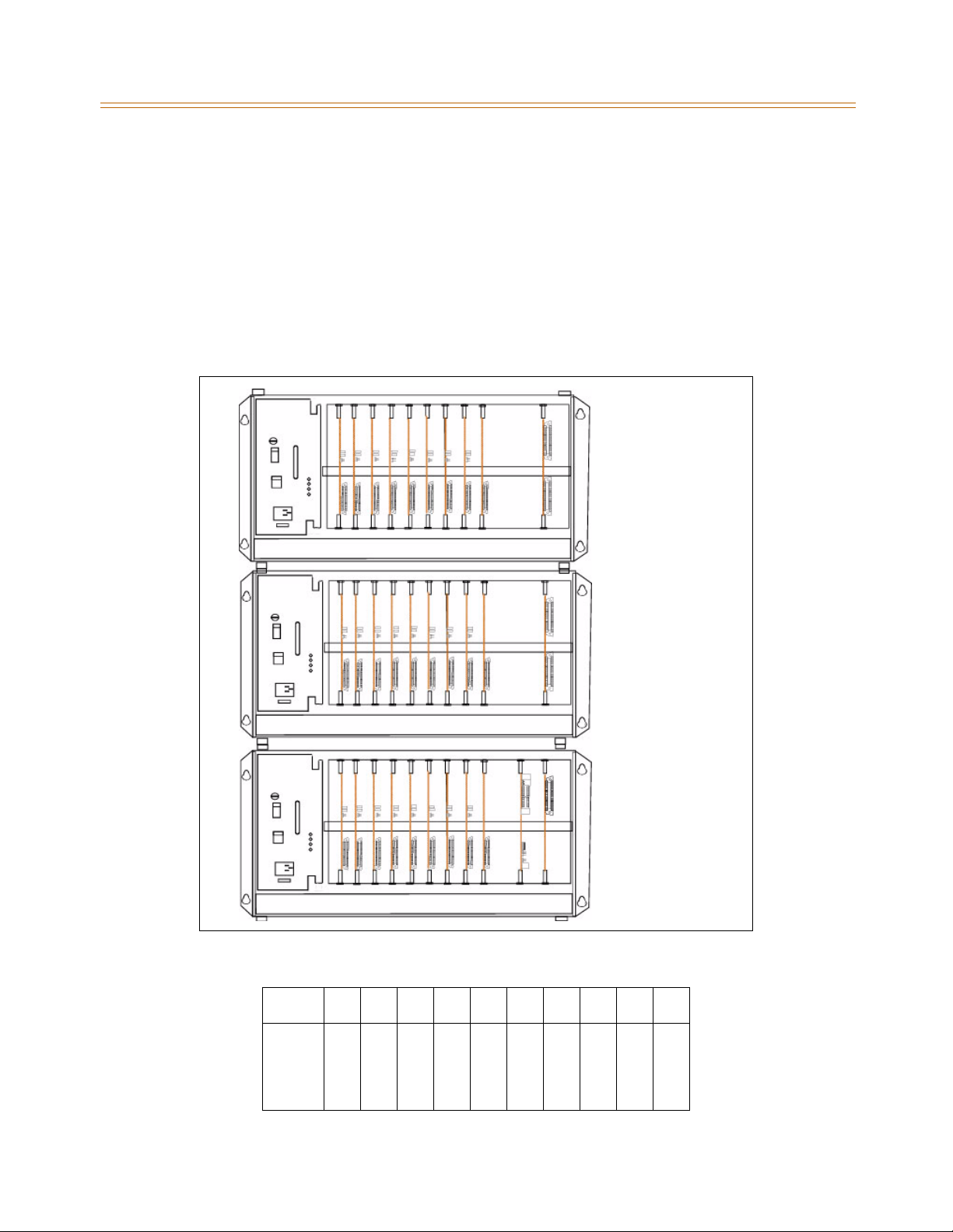
The Key Service Unit (KSU) is a metal frame cabinet designed for wall or rack mounting. It
contains a backplane with connectors that includea PSU slot, 9 universal slots, an MPB slot, an
LMU slot,a RAU slot, and PFTUand RGU connectors. The XTSKSU consists of Cabinet 0 and can
include optional Cabinets 1 and 2 for added capacity. Cable ties are located on the front edge
of the cabinet to allow connecting cables to be stored neatly.
The connecting cables for the stations and CO Lines exit through the outlet in the bottom of
KSU and can be connected to the Main Distribution Frame (MDF) or to a user installed
termination point.
CABINET 2
CABINET 1
CABINET 0
Figure 1-1: KSU Structure
SLOT0123456789
M
N
L
L
L
N
S
D
D
D
P
O
C
C
C
O
L
T
T
T
B
N
O
O
O
N
1
2
2
CARD
2
E
8
8
8
E
2
4
4
4
Figure 1-2: XTS Default Card Layout for Cabinet 0
Page 13

Product Description 1-5
Chapter 1 - Introduction
There are nine universal slots in the MB (slots 0-8). Any kind of peripheral card can be installed
in the universal slot, but a peripheral card that contains a CPU cannot be installed in Slot 8 of
Cabinet 0 (T1,PRIB,BRIB, VOIP,LCOBC,SLIBC). Thereare fixedslots forthePSU, PFTU,MPB, LMU,
RGU3, and RAU.
Power Supply Unit
A Power Supply Unit (PSU) is required in each Cabinet of the Key Service Unit. The PSU converts
commercial AC power (110 - 127 / 220 - 240V AC @ 50-60 Hz) to DC voltages, regulates the
voltages, and provides the appropriate DC voltages to the backplane for distribution to other
system components. Three DC outputs are provided: ±5V DC, +30V DC. LEDs in the PSU front
panel indicate valid outputs as well as the presence of AC input power.
The PSU includes circuitry to charge externally connected 24-volt batteries and controls
operation ofthe batteryback-up circuits.The PSU will provide system operating voltages from
the batteries ifcommercial ACpower fails.The battery back-upcontrol circuitryis incorporated
in the PSU to disconnect the batteries prior to a deep discharge or over-charge.
Ring Generator Unit
The Ring GeneratorUnit(RGU3) providesthering voltageto theSLIB circuitstoring theSLT. The
RGU3 also provides the input to the Message Wait source on the SLIB cards. The output of the
RGU3 is 65V AC, 25 Hz. The RGU3 can support simultaneous ringing for 15 SLTs.
The RGU3 is fitted on the lower right side panel inside the Cabinet.
Main Processing Board
The Main Processing Board (MPB) controls and manages communication between peripheral
interface, supervises all resources in the system, controls gain adjustment of PCM signal,
generates system tone, and manages call processing of the system. The two MPBs available for
use with the XTS are the MPB1 and MPB2. MPB1 is used for a single-cabinet installation only.
MPB1
The MPB1, incorporatesthe system'sRAM, master clock, 2RS-232C ports,and the system'sPCM
voice processing and main micro-processor. The microprocessor is a 32-bit high speed “RISC”
CPU which receives and transmits signaling information from/to other PCBs, controls feature
activation, and PCM time-slot interchange. The MPB has 4 built-in DTMF receivers.
LD1 is the PLLU Synchronization Indicator. This LED will be lit when the PLLU on the MPB has
synchronized with an external clock signal provided to the KSU via a BRI, PRI, or T1 circuit.
LD2-LD9 indicate the operation of the XTS system. LD10-LD13 are reserved for future use.
The MPB1 has the same features as the MPB2 described below, but does not include the
following: Paging Port, MOH Port, Port 5, or Ethernet Jack.
The Real-Time Clock and the 2 MB of SRAM that is associated with the system database are
protected in cases of power loss by a long life-high energy lithium battery. Onboard ROM
contains PCM tone, gain table, etc. needed for digital voice processing.
The 4 MB of flash ROM on the Program Module Unit (PMU) for the MPB1 contains basic system
operating software. A Modem Unit (MODU) can be installed on the MPB, for remote
programming.TheMPBcanonlybeinstalledintheMPBslotinCabinet0.
Add-on Boards: MODU and PMU
»
Page 14

1-6 Product Description
Chapter 1 - Introduction
MPB2
The MPB2, incorporatesthe system's RAM,master clock, 1external MOH port,1 external paging
port, 2 RS-232C ports, and the system's PCM voice processing and main micro-processor. The
microprocessor is a 32-bit high speed “RISC” CPU which receives and transmits signaling
information from/to other PCBs, controls feature activation, and PCM time-slot interchange.
The MPB has 4 built-in DTMF receivers.
LD1 is the PLLU Synchronization Indicator. This LED will be lit when the PLLU on the MPB has
synchronized with an external clock signal provided to the KSU via a BRI, PRI, or T1 circuit.
LD2-LD9 indicate the operation of the XTS system. LD10-LD13 are reserved for future use.
The Real-Time Clock and the 4 MB of SRAM that is associated with the system database are
protected in cases of power loss by a long life-high energy lithium battery. Onboard ROM
contains PCM tone, gain table, etc. needed for digital voice processing.
The 8 MB of flash ROM on the Program Module Unit (PMU) for the MPB2 contains basic system
operating software. A Modem Unit (MODU) can be installed on the MPB, for remote
programming.TheMPBcanonlybeinstalledintheMPBslotinCabinet0.
Add-on Boards: MODU and PMU
»
Miscellaneous Board
The MiscellaneousBoard (MISB)incorporates thecircuitry and interfaces for common optional
features including:
External Paging 2 ports
External Control Contacts 4 contacts
External BGM & MOH 2 ports
Alarm 1 input
RS-232C (optional SIU) 2 ports
An RJ21-type female connector is mounted on the front edge of the MISB for the connection
to the above circuits, exceptRS-232C serialinterfaces. OneMISB board can be installed in Slot 8
of Cabinet 0.
Add-on Board: SIU
»
Link Module Unit
The Link Module Unit (LMU) provides a link between the Cabinets of the KSU. LMU1 must be
installed to connect the Cabinet 0 to the Cabinet 1. The LMU2 is used to connect Cabinets 1
and 2. Signals are transmitted or received via linked cable.
Page 15

Product Description 1-7
Chapter 1 - Introduction
Extension Boards
Several types of extension boards are capable of supporting various types of telephones as
follows:
Table 1-1: Extension Boards
Board Name Function
DTIB12 Provides 12 Digital Telephone interfaces
DTIB24 Provides 24 Digital Telephone interfaces
ETIB Provides 12 Analog Telephone interfaces
SLIB Provides 6 Single Line Telephone interfaces
SLIBC Provides 12 Single Line Telephone interfaces with Caller ID
SLIBE Provides 12 Single Line Telephone interfaces
Digital Telephone Interface Board
The Digital Telephone Interface Board (DTIB) provides 2-wire interfaces for telephone
connection. Two versions are available (DTIB12 and DTIB24).
The DTIB provides digital voice and data communications to/from digital telephones.
An industry-standard amphenol-type female connector is mounted on the front edge of the
PCB for connection to the station interfaces. In addition, one LED is mounted on the PCB to
indicate the in use state of the connected telephones. It will turn on when one or more ports
are busy.
Add-on Boards: None
»
Electronic Telephone Interface Board
The Electronic Telephone Interface Board (ETIB) provides 2-wire interfaces for telephone
connection.
An industry-standard amphenol-type female connector is mounted on the frontof theETIB for
connection to the station interfaces.
Add-on Boards: None
»
Single Line Telephone Interface Board
The Single Line Telephone Interface Board (SLIB) provides 2-wire interfaces for telephone
connection. Three versions are available (SLIB, SLIBE, and SLIBC).
Six RJ11 connectors are mounted on the front edge of the SLIB for connection to the station
interfaces. An industry-standard amphenol-type female connector is mounted on the front of
the SLIBE and SLIBC for connection to the station interfaces.
Add-on Boards: DTRU and MSGU on SLIB, DTRU4 and MSGU48 on SLIBE and SLIBC.
»
Page 16

1-8 Product Description
Chapter 1 - Introduction
CO Interface Boards
The types of CO Interface boards are listed in the table and narrative that follow.
Table 1-2: CO Interface Boards
Board Name Function
DIDB Provides 4 Direct Inward Dial Lines
LCOB Provides 6 Loop Start CO Lines
LCOBC Provides 8 Loop Start CO Lines with Caller ID
LCOBE Provides 8 Loop Start CO Lines
VOIP Provides 8 VOIP interface over LAN
T1IB Provides 24 channels
PRIB Provides 23 bearer channels and 1 data channel
BRIB Provides 2 bearer channels and 1 data channel
Direct Inward Dial Board
The DirectInward Dial Board (DIDB) provides four analog DID CO interface ports. The DIDB can
be optionally equipped with a DTMF Receiver Unit (DTRU) to detect DTMF tones. If a DIDB is
used, a DTRU is required; it does not necessarily have to be mounted on the DIDB, but it must
be installed within the system.
Add-on Boards: DTRU
»
Page 17

Product Description 1-9
Chapter 1 - Introduction
Loop Start CO Line Interface Board
The Loop Start CO Line Interface Board (LCOB) provides Loop Start CO Lines which support
pulse/DTMF signal.Each interfacecontains ring and loop current detection circuits, Analog-toDigital and Digital-to-Analog conversions, and pulse and ground flash signaling circuits. The
LCOB contains LEDs to indicate the in use status of each CO Line.
Three versions are available: LCOB, LCOBC, and LCOBE.
The LCOB has three RJ14 modular connectors.
The LCOBE and LCOBC have an RJ21-type male connector.
The LCOB can be equipped with a DTMF receiver unit (DTRU) to detect DTMF tones.
Add-on Boards: DTRU for LCOB, DTRU4 for LCOBE and LCOBC
»
Voice Over the Internet Protocol Card
The Voice Over the Internet Protocol (VoIP) card provides up to eight lines per card (two lines
per installed VOIP module). The VoIP card allows bi-directional voice communication to other
devices via an IP network such as an internal Local Area Network (LAN), the Internet, or a Wide
Area Network (WAN) using the Ethernet Interface. It monitors for disconnect while using
minimal bandwidth. It also provides four-digit dialing and other features.
Add-on Boards: VoIP modules
»
T1 Interface Board
The T-1Interface Board (T1IB) provides the T-1 (1.544Mbps,24-Voice Channel) digital interface
circuit, control circuitry, and synchronous clock control circuits. DTMF tone detection units can
be installed optionally on the T1IB. The T1IB has 8 LEDs on the front edge of the PCB which
indicates errors of T-1 line, in-use status, and synchronous clock enable status.
Add-on Boards: DTRU4
»
Primary Rate Interface Board
The Primary Rate Interface Board (PRIB) provides one Primary Rate Interface circuit. Each circuit
contains 23 bearer and one data channel (23B+D). When a PRIB card is programmed into the
system, the system interprets all B channels as trunks. Thus, one PRIB which contains 23B+D
circuits provides 23 line appearances to the system. The PRIB card uses 24 time slots when
installed.
The PRIB must usually beused in conjunction with a Channel Service Unit (CSU). Connection is
made viaa DB15 from the PRIB to the CSU.When networking systems that areless than 50 feet
apart, no CSU is required.
The PRIB accepts two DTRU4 boards.
When ordering PRI lines from the telephone company, specify ESF framing and B8ZS line
coding. PRI only supports National ISDN 2 (NI-2). No other standards are supported.
Add-on Boards: DTRU4
»
Page 18

1-10 Product Description
Chapter 1 - Introduction
Basic Rate Interface Board
The Basic Rate Interface Board (BRIB) interface provides four Basic Rate Interface circuits. Each
circuit is comprisedof twobearer (64Kbps each) andone data(16Kbps) channels (2B+D). When
a BRIBis programmed into the system, the systeminterprets all B channels as trunks. Thus,one
BRIB which contains four 2B+D circuits provides eight line appearances to the system. A
maximum of seven BRIBs can be installed into the system (56 B channels).
The BRIB uses the U interface of the BRI standard. Connection to the network is made via RJ45
connectors on the front edge of the board. No CSU is required to connectto the central office.
The BRIB card uses eight time slots when installed.
When ordering BRI lines from the telephone company, specify Capability P as the ordering
code. National ISDN 1 (NI-1) is supported. No other standards are supported.
Add-on Boards: DTRU4
»
Add-On Boards
This section describes add-on boards, which can be installed on various types of boards to
support additional functions as shown in the following table.
Table 1-3: Add-on Boards
Board Function Position
DTRU Two DTMF receiver circuits LCOB, SLIB, DIDB
DTRU4 Four DTMF receiver circuits LCOBE, LCOBC,
MSGU Provides message waiting light indication on SLTs SLIB
MSGU48 Provides message waiting light indication on SLTs SLIBE & SLIBC
PMU Provides operating software MPB
MODU Provides a 19.2K baud modem for local access MPB
RAU Provides three relay contacts and two alarm
functions (not used)
SIU Provides additional two RS232 serial interfaces. MISB
SLIBE, SLIBC, T1IB,
PRIB, & BRIB
RAU
Dual Tone Receiver Unit
The dual tonereceiver unit (DTRU)provides Dual ToneMulti frequency (DTMF)circuits. The two
versions of the DTRU are: the DTRU and the DTRU4.
The DTRU can be installed on the LCOB, SLIB, or DIDB to provide 2 DTMF circuits.
The DTRU4 can be installed on the LCOBE, LCOBC, SLIBE, SLIBC, T1IB, or PRIB to provide
4 DTMF circuits.
The resources above are shared across the entire system.
Page 19

Product Description 1-11
Chapter 1 - Introduction
Message Waiting Unit
The message waiting unit (MSGU) provides a message waiting light indication on single line
telephones.
One MSGU can be installed on each SLIB (required if message wait indication is needed).
One or two MSGU48s can be installed on each SLIBE or SLIBC (required if message wait
indication is needed).
Program Module Unit
The CPU operates oncode inthe flashROMs inthe Program Module Unit (PMU) whichcontains
the system control,administration, and callprocessing. ThePMU has 8MB of ROM(4 MBin PMU
for MPB1).
The PMU must be installed on the MPB.
»
Modem Unit
The Modem Unit(MODU) (Modulator& Demodulator Unit)provides a communication method
interface for remote maintenance and remote PC Admin. It operates in full-duplex,
asynchronous modes at line rates up to 19.2 Kbps.
The Modem Unitprovidesan asynchronousmodemfor access tothe system databaseand fault
reporting features from a remote site. Themodem maybe connectedto a pre-selected CO Line
through the system-switching matrix. The MODU port is independent of the SIU standard
RS-232C port, allowing system database access, etc., without the need to interrupt the SMDR
output.
The optional MODU is installed on the MPB.
»
Relay Alarm Unit
The Relay Alarm Unit (RAU) provides three relay contacts and two alarm functions.
Serial Interface Unit
The Serial Interface Unit (SIU) provides an additional two RS-232C(ports 3& 4)interface circuits
on the MISB. The SIU is useful for SMDR print out and Caller ID. The following is a list of the
system’soutput:
On-line SMDR
Statistical information
Caller ID input
ACD
The optional SIU can be installed on the MISB.
»
Page 20

1-12 Product Description
Chapter 1 - Introduction
Page 21

System Specifications
2
This chapter describes the hardware used by the XTS system and lists the specifications
for each component.
Page 22

» » » » » » » NOTES
» » » » » » »
Page 23
System Capacities 2-3
Chapter 2 - System Specifications
System Capacities
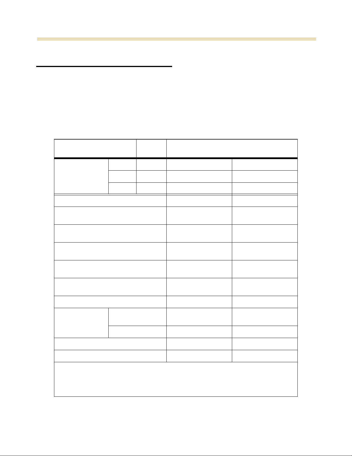
The following tables and charts describe system capacities and display the configuration
flexibility of the system.
The KSUcontains a PSU slot, nine universal slots,one MPB slot, one LMU slot, oneRAU slot, and
PFTU and RGU connectors.
Table 2-1: System Capacity
Description
Cabinet 0 9 136 Time Slots 136 Time Slots
Time Slots*
KSU Cabinets 3 Cabinets 1 Cabinet
Serial Ports (RS-232C) 4 Ports
Alarm 3 Inputs
External Control Contacts 7 Contacts
Music Source Inputs 3 Inputs
DTMF Receivers 24 Receivers
Power Fail Circuits 30 Circuits 30 Circuits
Cabinet 1 9 96-144 Time Slots** N/A
Cabinet 2 9 96-144 Time Slots** N/A
Universal
Slots
MPB2 MPB1
(MPB: 2, MISB: 2)
(RAU: 2, MISB: 1)
(RAU: 3, MISB: 4)
(MPB: 1, MISB: 2)
(MPB:4,SLT/COcards:20)
Usable Capacity
3Ports
(MPB:1, MISB:2)
3 Inputs
(RAU: 2, MISB: 1)
7Contacts
(RAU: 3, MISB: 4)
2Inputs
(MPB: 0, MISB: 2)
24 Receivers
(MPB:0,SLT/COcards:24)
Paging Zones
DSS/BLF Consoles 3 Consoles (per station) 3 Consoles (per station)
Ethernet Connection 1 N/A
* Time slots are used to support each CO Line and each station. A Cabinet cannot support more than 96 stations.
** Maximum time slots on Cabinet 1and Cabinet 2 can range from 96 to 144 each, but the total time slots between the
two Cabinets cannot exceed 240.
*** MPB1 - Maximum COs are 48 and maximum stations are 96
MPB2 - Maximum COs are 144 and maximum stations are 252
External 3 Zones
(MPB: 1, MISB: 2)
Internal 8 Zones 8 Zones
2 Zones
(MPB: 0, MISB: 2)
Page 24

2-4 System Components
Chapter 2 - System Specifications
System Components
This table shows the slot positions for each card that can be installed in the XTS System.
Table 2-2: System Card Description
Part
Number
8031-41 BRIB 8 1-7 or 0-7 Basic Rate Interface Board
8031-10 DIDB 4 1-8 or 0-8 Direct Inward Dial Board
8032-30 DTIB12 12 0-8 Digital Telephone Interface Board
8032-40 DTIB24 24 0-8 Digital Terlephone Interface Board
8031-50 DTRU --- LCOB, SLIB, DIDB DTMF Receiver Unit (2 port)
3031-60 DTRU4 --- LCOBE, LCOBC,
8032-20 ETIB 12 1-8 or 0-8 Electronic Telephone Interface Board
3000-00 KSU --- --- Key Service Unit
8031-00 LCOB 6 1-8 or 0-8 Loop Start CO Interface Board
3031-02 LCOBE 8 1-8 or 0-8 Loop Start CO Interface Board (01, 3Q)
3031-03 LCOBC 8 1-7 or 0-7 Loop Start CO Interface (01, 3Q) with Caller ID
3035-01 LMU1 --- LMU Link Module Unit (Cabinet 0 only)
Board
Numberof
Time Slots
Slot
Position
SLIBE, SLIBC,
T1IB, PRIB, BRIB
Description
DTMF Receiver Unit (4 port)
3035-02 LMU2 --- LMU Link Module Unit (Cabinets 1 & 2 only)
8035-00 MISB --- 8 only Miscellaneous Board (Cabinet 0 only)
3030-30 MODU --- MPB 19.2 Kbps Internal Modem
3030-01 MPB1 --- MPB Main Processing Board = 136 Time Slots Usable
3030-03 MPB2 --- MPB Main Processing Board = 376 Time Slots Usable
8033-10 MSGU --- SLIB Message Waiting Unit
3033-10 MSGU48 --- SLIBE, SLIBC Message Waiting Unit
8036-00 PFTU --- --- Power Failure Transfer Unit
The first range, for entriesthat show two rangesof slot positions, appliesto Cabinet 0. For example,the LCOBC card canbe
used in slot 1-7 of Cabinet 0 and in slots 0-7 in either Cabinet 1 or Cabinet 2.
Page 25

System Components 2-5
Chapter 2 - System Specifications
Table 2-2: System Card Description
Part Num-
ber
3030-10 PMU --- MPB1 Program Module Unit, 4 MB ROM
3030-20 PMU --- MPB2 Program Module Unit, 8 MB ROM
8031-40 PRIB 24 1-7 or 0-7 Primary Rate Interface Board
3071-10 PSU --- PSU Power Supply Unit, 350W
3035-03 RAU --- RAU Relay Alarm Unit (used only in Cabinet 0)
3073-00 RGU3 --- --- Ring Generator Unit (25Hz) : Sine Wave, Internal
8035-10 SIU --- MISB Serial Interface Unit
8033-00 SLIB 6 1-8 or 0-8 Single Line Interface Board
3033-03 SLIBC 12 1-7 or 0-7 Single Line Interface Board with Caller ID
3033-02 SLIBE 12 1-8 or 0-8 Single Line Interface Board
8031-31 T1IB 24 1-7 or 0-7 T1 Interface Board
TR8037-02 VOIP 8 1-7 or 0-7
TR8037-04 VOIP 8 1-7 or 0-7
Board
Numberof
Time Slots
Slot
Position
Discovery
Discovery
Description
VoIP Card w/one VoIP Module
VoIP Card w/two VoIP Modules
TR8037-06 VOIP 8 1-7 or 0-7
TR8037-08 VOIP 8 1-7 or 0-7
TR8037-10 Module 2 VOIP
The first range, for entries that show two ranges of slot positions, applies to Cabinet 0. For example, the T1IB card can be
used in slot 1-7 of Cabinet 0 and in slots 0-7 in either Cabinet 1 or Cabinet 2.
Discovery
Discovery
Discovery
VoIP Card w/three VoIP Modules
VoIP Card w/four VoIP M odules
VoIP module only (for upgrade)
Page 26
2-6 System Configuration Tables
Chapter 2 - System Specifications
System Configuration Tables
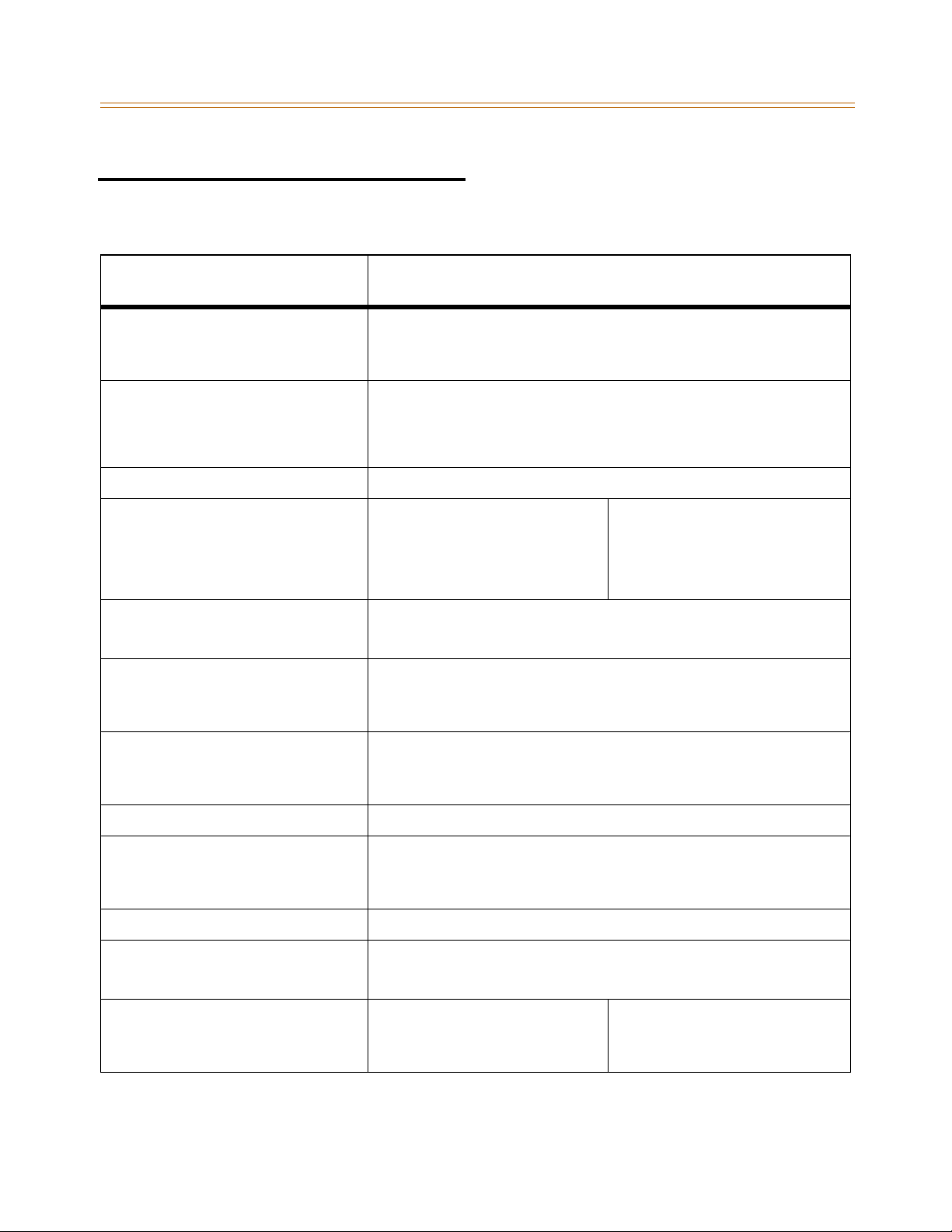
Table 2-3: System Capacity
Item
Account Codes
Number of digits per account code
Number of Account Codes- Unverified
Number of Account Codes - Verified
ACD Groups
Groups
Members
RAN Announcements
Calls in Queue
Attendants Up to 3 stations can be designated as Attendants.
CO Lines
CO/PBX/Centrex Lines
DID Lines
T-1 Trunks
ISDN Trunks
Conference
Circuits
Parties
Dialing Memory
Station Speed Dialing
System Speed Dialing
Total Speed Dial
Up to 12 unverified digits
Unlimited
250 Account Codes
Softwaresupportsupto16Groups
Software supports up to 252 stations in each Group
Eight RAN Announcements per system, 3 per ACD Group
All CO Lines may be queued for an ACD Group
MPB1
48 maximum
10 Conferences per system
8 parties per conference, of which 5 can be external
20 Bins per station (24-digits)
980 Bins per system (24-digits)
3000 Bins per system (24-digits)
Capacity
MPB2
144 maximum
Digital DSS/BLF Units 180 maximum
DISA Circuits Unlimited number of CO lines may be programmed simultaneously.
Hunt Groups
Groups
Members
Types
Loop Supervision Disconnect 700 msec. duration (CO or Internal call to SLT)
Music Channels
Music-On-Hold/Background Music 8 Channels per system (4-8 on CO, ports 1 & 2 on MISB, port 3 on MPB2) (port 3 is
Page Zones
Internal Paging
External Paging
Each DSS/BLF unit requires 1 station port and reduces station capacity by 1.
DSS/BLF maps may not be duplicated at one station.
1 station may have up to 3 DSS/BLF units associated with it.
Softwaresupportsupto8Groups
Softwaresupportsupto8stationsineachGroup
Station, Pilot Hunting, or Pilot Ring All
unavailable for MPB1)
MPB1
8 maximum (software controlled)
2 maximum
8 maximum (software controlled)
3 maximum
MPB2
Page 27
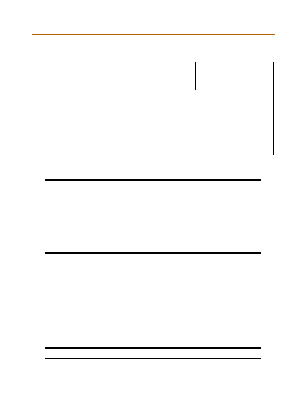
System Configuration Tables 2-7
Chapter 2 - System Specifications
Table 2-3: System Capacity
Stations
Analog Stations
Digital Telephones
Single Line Telephones
UCD Groups
Groups
Members
RAN Announcements
Calls In Queue
Voice Mail Group s
Groups
Members (ports)
Integration Method
Positive Disconnect
VM Message Wait
VM Disconnect Signal
Softwaresupportsupto8Groups
Softwaresupportsupto8stationsineachGroup
Eight RAN Announcements per system, 2 per UCD Group
All CO Lines may be queued for a UCD Group
Softwaresupportsupto8Groups
Software supports up to 24 stations per group
In-Band signaling (DTMF)
Loop supervision is provided to ensure disconnect
Programmable 12-digit (DTMF) string
If 0 digits are programmed, 15 sec of silence are followed by a busy tone.
MPB1
96 maximum
Table 2-4: Environment Specification
Item Degrees (ºF) Degrees (ºC)
Operation Temperature 32-104 0-40
Optimum Operation Temperature 68-78 20-26
Storage Temperature 32-158 10-70
MPB2
252 maximum
No more than 96 stations are
supported per Cabinet.
Relative Humidity 0-80% non-condensing
Table 2-5: Loop Limits
Item
Analog Electronic Telephone* Maximum length of station loop:
1000 feet of 24 AWG
(4 wire, inside wiring, twisted cable)
Digital Telephones* Maximum length of station loop:
1000 feet of 24 AWG
(2-wire, inside wiring, twisted cable)
Single Line Telephones* 2000 feet of 24 AWG
*All stations must be installed in the same building. Station circuitry does not contain protection to support offpremise operation.
Capacity
Table 2-6: FCC Registration Numbers
System
For a Key System configuration (button appearance) KF: 5JYKOR-45505-MF-E
FCC Number
For a Hybrid System configuration (dial access codes) MF: 5JYKOR-45505-MF-E
Page 28
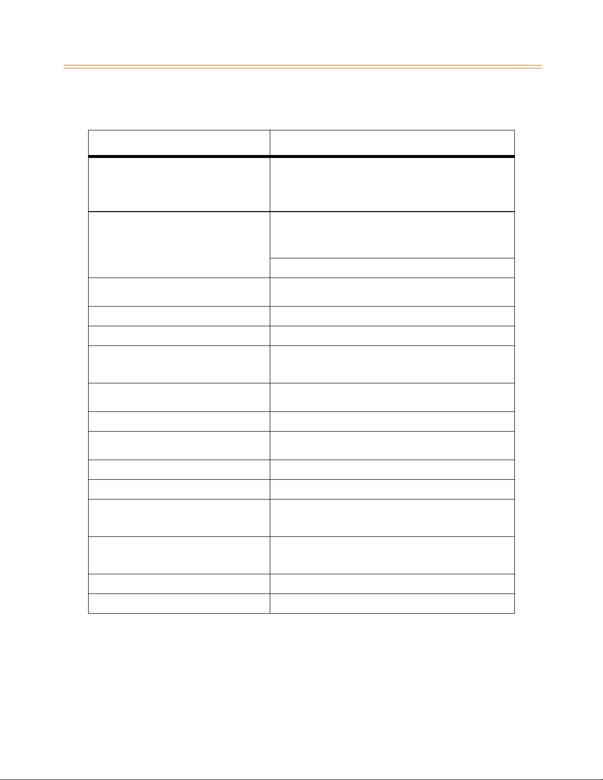
2-8 System Configuration Tables
Chapter 2 - System Specifications
Table 2-7: Electrical Specifications
Item
Power Supply
AC Voltage Input
AC Power
AC Input Fuse
DC Output Voltage
Battery Backup
Input Voltage
Battery Fuse
Charging Current
External Relay Contact 1 amp @24Volt DC
Longitudinal Balance 60 db from 200 Hz to 1,000 Hz
Idle Channel Noise Less than 15 dbrnco for all connections
Cross Talk Attenuation Greater than 75 dbm Station to CO and Station to Station
Single Frequency Distortion
(300 - 3400 Hz)
Ringing Detect Sensitivity 40Vrms @16-30Hz
Ringer Equivalence Number (REN) LCOB: 0.8B; DIDB: 0.0B; T1IB: 6.0P
120 or 220 +/- 10% Volt AC @48-63Hz
350W
5.0 amp @ 220Volt AC
+ 5V @ 10A, - 5V @ 1.5A, + 30V @ 8.4A
24Volt DC
12.5amp @250Volt AC
Maximum 1A
40 db from 1000 Hz to 4000 Hz
Station to CO Line and station to station:
Better than 2.0% or 34 db for an
Output level -30 dbm to 0 dbm
30Vrms @30-37Hz
Specification
Co Line Signaling - DTMF Frequency pair at ±5dbm
CO Line Signaling - Dial Pulse 10 pps and 20 pps programmable
Input Level Range +10 db maximum
Music Source
Music-On-Hold input
Background Music input
External Page Port
Output Impedance
Output Power w/o Compression
CSA File Number (NRTL/C) LR57228
Telephone Transmitter Electret mic compatible
Frequency tolerance ±1.5%
600Ω input at Ødbm maximum from music source
600Ω input at Ødbm maximum from music source
600Ω @ 0dbm
5 milliwatt max
Page 29
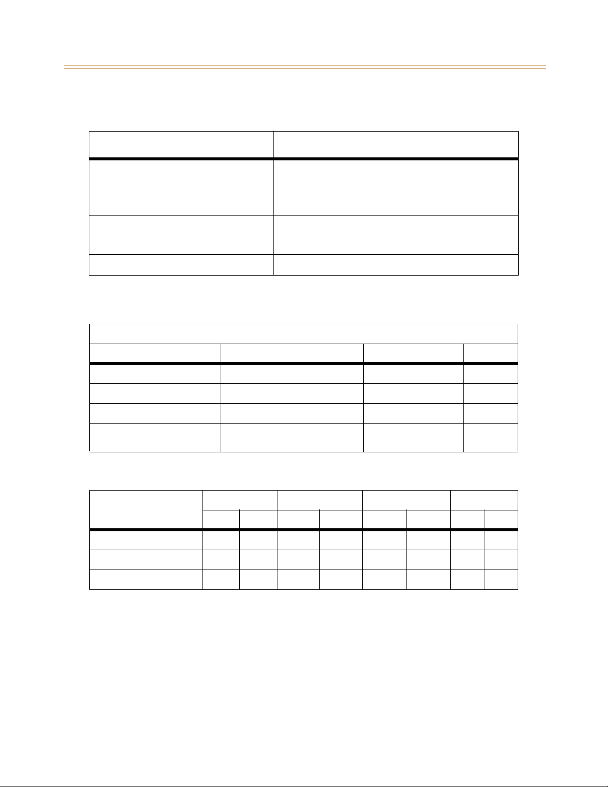
System Configuration Tables 2-9
Chapter 2 - System Specifications
Table 2-8: Dialing Specifications
Item
DTMF Dialing
Frequency Deviation
Rise Time
Duration of DTMF Signal
Interdigit Time
Pulse Dialing
Pulse Dialing Rate
Pulse Break/Make Duration
CO Type Loop Start, 600 ohm, current sensing
Less than +/-1%
Maximum 3ms
Minimum 75ms
Minimum 75ms
10 or 20 pps
60/40% or 67/33%
Specification
Table 2-9: Trunk Ordering Info: Public Network/Private Lease Lines
System Port Identification, Facility Interface and Service Order Codes
Interface Card Ringer Equivalent Number (REN) Facility Line Interface Jack Type
CO Port (LCOB) 0.8B 02LS2 RJ11
CO Port (LCOBE/LCOBC) 0.8B 02LS2 RJ21X
Direct Inward Dial (DIDB) 0.0B 02RV2-T RJ11
T-1 Port (T1IB) or
ISDN Port (PRIB)
6.0P 04DU9-B RJ45
Table 2-10: Dimension and Weight
Item
KSU 16.2 411 24.8 630 9.4 238 25.3 11.5
Digital Keyset 9.3 236 7.6 192 3.3 84 3.3 1.5
Digital DSS/BLF Console 9.3 236 4.9 125 2.4 62 2.0 0.9
Height Width Depth Weight
in mm in mm in mm lbs kg
Page 30
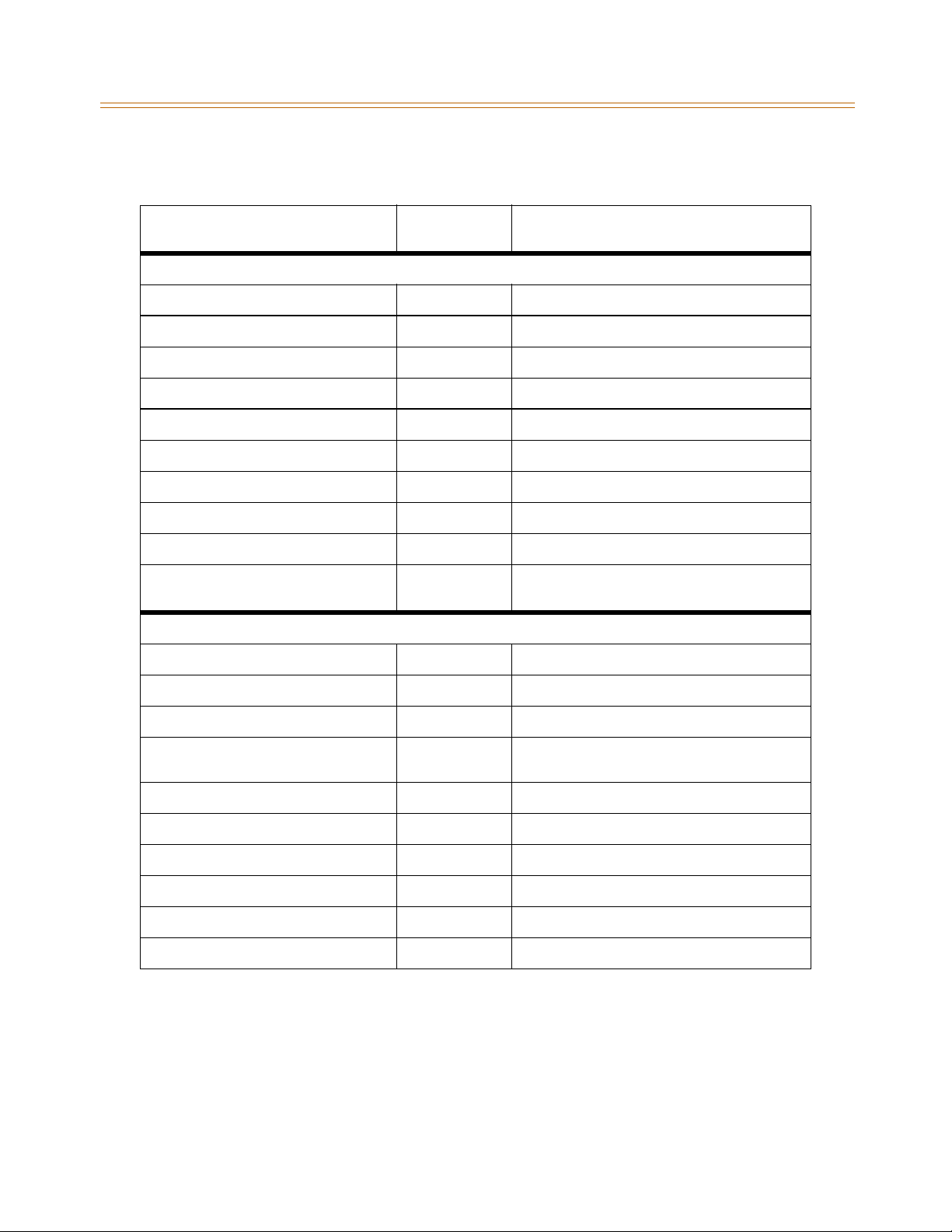
2-10 System Configuration Tables
Chapter 2 - System Specifications
Table 2-11: Electronic Telephone Audible Signals
Type of Signal Frequency
Electronic Telephone Signals
Incoming CO Line 440+480 0.4 on/0.4 off/0.4 on/2.0 off; Repeated
Intercom Tone Ringing 440+480 0.8 on/2.4 off; Repeated
Intercom Call Announce (H-P modes) 440 0.2 on/0.2 off; (3 bursts)
Transferred CO Line 440+480 0.8 on/2.4 off; Repeated
CO Line Recall 440+480 0.24 on/0.6 off; Repeated
Message Wait Call Back 440+480 0.8 on/2.4 off; Repeated
CO Queue Call Back 440+480 0.8 on/2.4 off; Repeated
Camp-On 440 0.8on(1burst)
Paging Alert Tone 440 1.0 on
Type of Signal Frequency
Electronic Telephone Confidence Tones
Intercom Ringback 440+480 0.8 on/2.4 off
(in seconds unless otherwise indicated)
(in seconds unless otherwise indicated)
Signal Duration
Signal Duration
Transferred CO Line 440+480 0.8 on/2.4 off
Call Announce 440 0.2 on/0.2 off; (3 bursts)
Busy Tone 480+620 1.0 on/0.2 off/1.0 on/0.2 off/0.2 on/ 0.2 off/
Error Tone 480+620 0.2 on/0.1 off; Repeated
Intercom Dial Tone 350+440 Steady
DND Tone 350+440 0.4 on/0.4 off/0.2 on/0.2 off/0.2 on; Repeated
Paging Confirmation Tone 350+440 1.0 on
Conference Time-out/Re-Enter Tone 440 Programmable Steady Tone
Confirmation Tone 350+440 0.2 on/0.2 off; (3 bursts) CO/PBX
0.2on/0.2 off/0.2 on; Repeated
Page 31
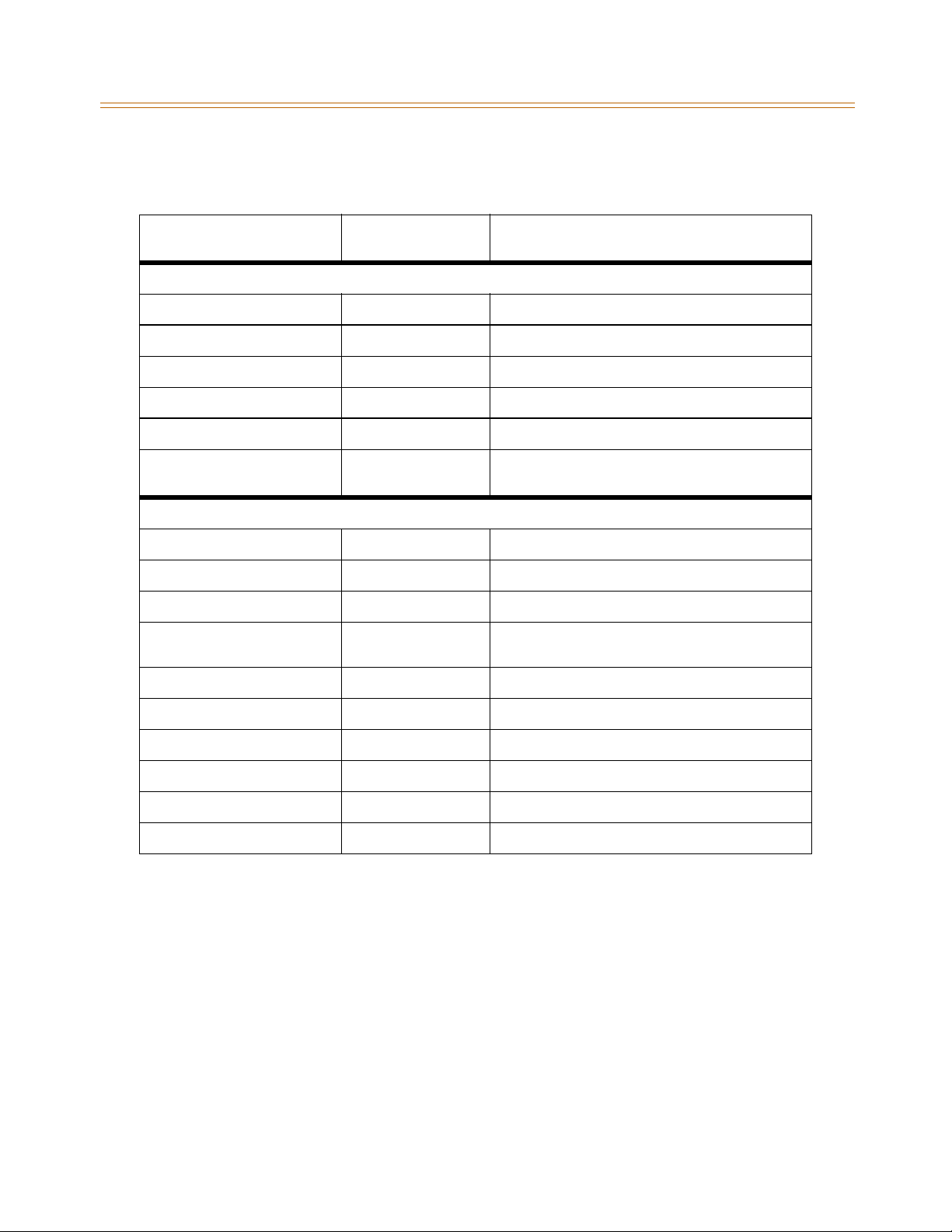
System Configuration Tables 2-11
Chapter 2 - System Specifications
Table 2-12: Single Line Audible Signals
Type of Signal Frequency
Single Line Signals
Incoming CO Line 20Hz 90 VAC 2.0 on/4.0 off; Repeated
Intercom Tone Ringing 20Hz 90 VAC 1.0 on/0.2 off/1.0 on/4.0 off; Repeated
Transferred CO Line 20Hz 90 VAC 1.0 on/0.2 off/1.0 on/4.0 off; Repeated
CO Line Recall 20Hz 90 VAC 2.0 on/4.0 off; Repeated
CO Queue Call Back 20Hz 90 VAC 1.0 on/2.0 off; Repeated
Type of Signal Frequency
Single Line Confidence Tones
Intercom Ringback 440+480 1.0 on/3.0 off
Transferred CO Line 440+480 1.0 on/0.2 off/1.0 on/4.0 off
Call Announce 440 0.2 on/0.2 off; (3 bursts)
Busy Tone 480+620 1.0 on/0.2 off/1.0 on/0.2 off/0.2 on/ 0.2 off/0.2on/
(in seconds unless otherwise indicated)
(in seconds unless otherwise indicated)
0.2 off/0.2 on; Repeated
Signal Duration
Signal Duration
Error Tone 480+620 0.2 on/0.1 off; Repeated
Intercom Dial Tone 350+440 Steady
DND Tone 350+440 0.2 on/0.2 off/0.2 on/0.2 off/0.2 on/0.2 off; burst
Paging Confirmation Tone 350+440 1.0 on
Conference Time-out Tone 440 Programmable Steady Tone
Confirmation Tone 350+440 0.2 on/0.2 off; (3 bursts)
Page 32
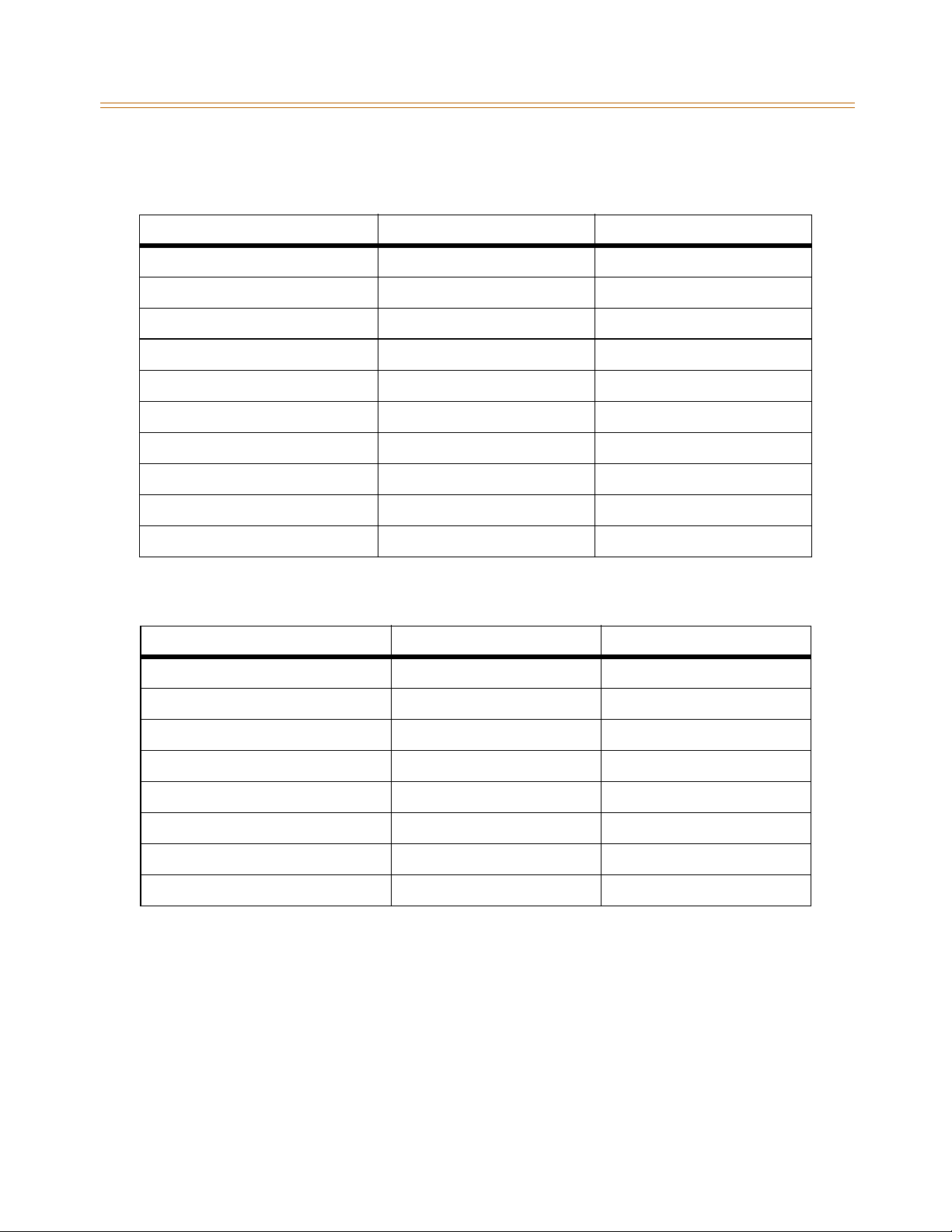
2-12 System Configuration Tables
Chapter 2 - System Specifications
Table 2-13: Digital Station Visual Signals - CO Line Buttons
Feature/Function Flash Rate LED Color
Incoming CO Ringing 60 ipm double wink Red
Transferred CO Ringing 120 ipm Flash Red
CO Line Recalling 480 ipm Flutter Red
System HOLD 60 ipm double wink Red
Exclusive HOLD (I-Hold) 120 ipm Flash Green
I-HOLD (System) 60 ipm wink Green
CO Line Queue Call Back 480 ipm Flutter Red
CO Line in Use ON Steady Red
CO Line Idle OFF
Exclusive Hold (other stations) ON Steady Red
Table 2-14: Digital Station Visual Signals - DSS/BLF Buttons
Feature/Function Flash Rate LED Color
Off-Hook (Busy) ON Steady Red
Incoming Intercom Ring 120 ipm Flutter Red
Call Announce (H or P Mode) Steady Red
Message Waiting Call Back 120 ipm Flutter Red
Station in Do Not Disturb 60 ipm Double Flash Red
Camp On (by station) 120 ipm Flash Red
Automatic Call Back 120 ipm Flash Red
Station Unavailable (ACD/UCD) 60 ipm Flash Red off (3 bursts)+480
Page 33
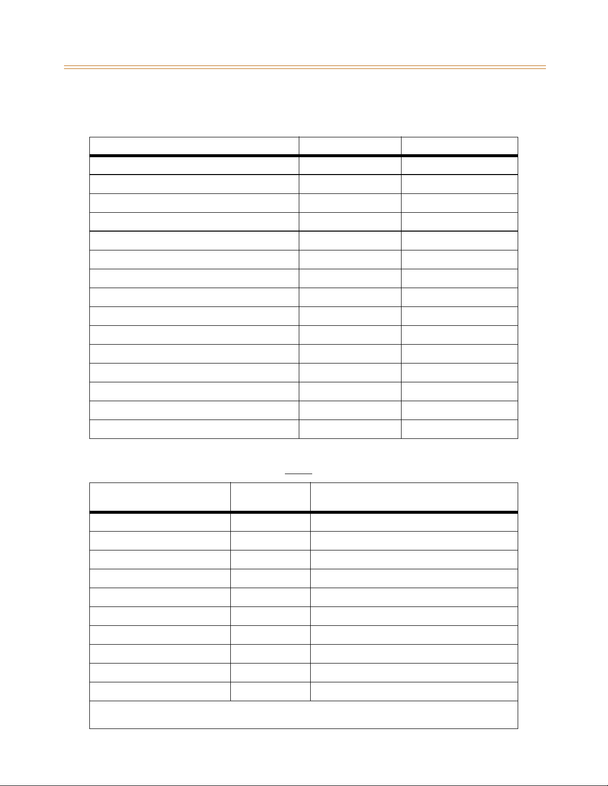
System Configuration Tables 2-13
Chapter 2 - System Specifications
Table 2-15: Digital Station Visual Signals - Feature/Function Buttons
Feature/Function Flash Rate LED Color
Call Forward (active) Steady Red
Message Wait (active) Steady Red
Camp On (active) 120 ipm Flash Red
Call Back (active-initiator) 120 ipm Flash Red
CO Line Queue (active) 480 Flutter Red
DND (active) Steady Red
Mute Steady Red
On/OFF Steady Red
Conference Steady Red
Speed (moment on until bin address dialed) Steady Red
Personalized Messages 15 ipm Flash Red
Tone Intercom Call (Hold button) 15 ipm Flash Red
Loop same as CO Green/Red
Pool same as CO Green/Red
Transfer 60 ipm Flash Green
Table 2-16: Signals to Called Station (Digital Station)
Feature (Indication) Sound in Hz
Incoming CO Line (*user selectable) 0.4 on/0.4 off/0.4 on/2.0 off
Intercom Tone Ringing (*user selectable) 0.8 on/2.4 off; Repeated
Intercom Call Announce (H & P) 935 0.2 on/0.2 off; (2 bursts)
Transferred CO Line (*user selectable) 0.2 on/0.2 off; (2 bursts)
CO Line Recall (*user selectable) 0.2 on/0.6 off; Repeated
Message Waiting Call Back (*user selectable) 0.8 on/2.4 off; Repeated
Queued CO Line Call Back (*user selectable) 0.2 on/0.6 off; Repeated
(in seconds unless otherwise indicated)
Occurrence - Cadence
Camp On 935 0.8 second burst
Alarm Tone - Repeated 701/857 1.0 on/.25 off; Repeated
Alarm Tone - Single (Continuous) 701/857 1.0 on; (once every 30-60 seconds until alarm is reset)
* Only one (1) tone can be selected by a station at a time. This tone is used for all signaling that uses the “User
Selectable” tone.
Page 34
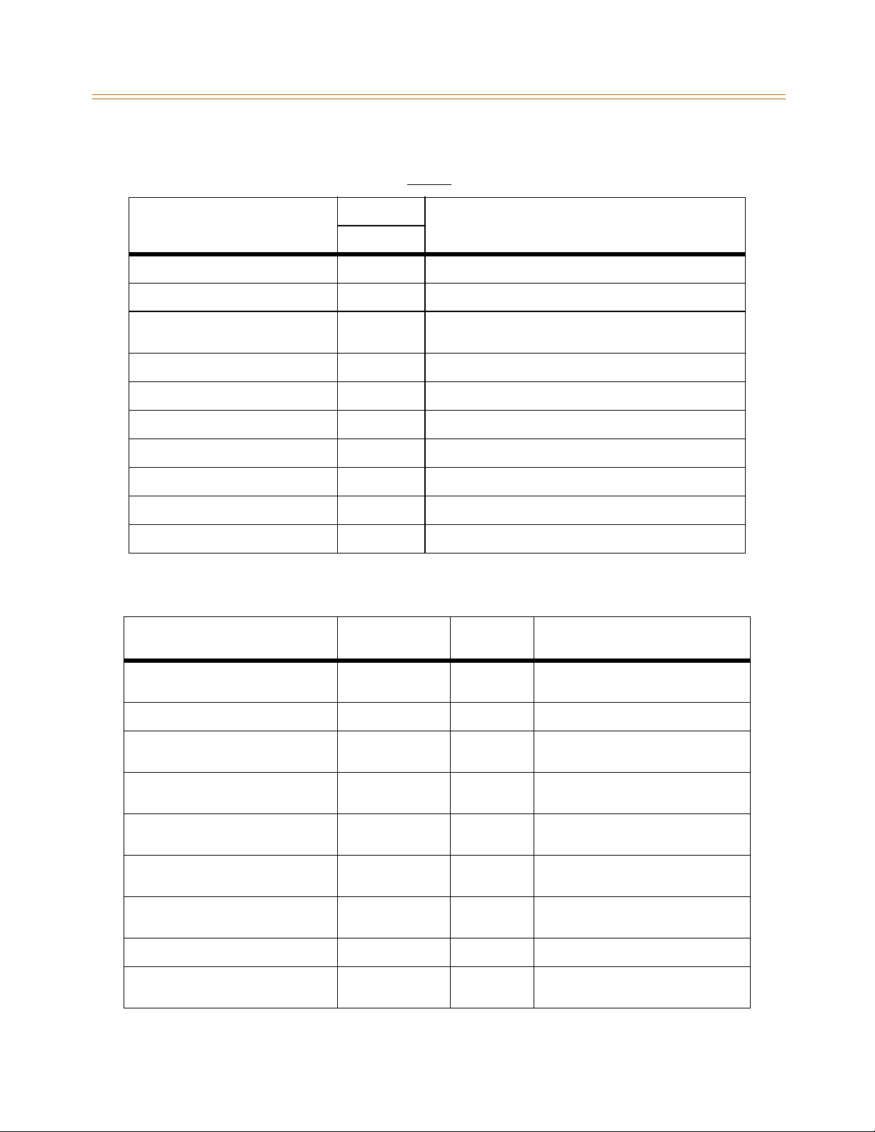
2-14 System Configuration Tables
Chapter 2 - System Specifications
Table 2-17: Signals to Calling Station (Digital Station)
Feature (Indication)
SoundinHz
Station
Intercom Ring Back Tone 1215/1471 1.0 on/2.8 off; Repeated
Intercom Call Announce 935 0.2 on/.24 off; three (3) times (HF mode)
Busy Tone 701 1.0 on/0.2 off/ 1.0 on/0.2 off/0.6 on/0.6 off/0.2 on/0.2off/
0.2 on/0.2 off/0.2 on/0.2 off
Error Tone 701 0.2 on/0.1 off; Repeated
Intercom Dial Tone 420 Continuous
DND Tone 701 0.26 on/0.2 sec off/0.2 on/0.2 off/0.2 on/0.6 off; Repeated
Paging Confirmation Tone 935 1 second burst
Conference Time Out Warning Tone 420 1 second burst
Programming Confirmation Tone 440 three 100ms bursts
Programmed Error Tone 1471 0.2 on/0.2 off; Six (6) times
Occurrence - Cadence
(in seconds unlessotherwise indicated)
Table2-18:VoiceMailConfidenceTones
VM Condition Action Tone Received Sound In Hz
OffHook InternalDialTone
Calls an Internal Station (idle) Ring Back Tone 440/480 0.8 on/2.4 off; Repeated
Initiate a Transfer (hook-flash) Internal Dial Tone
Calls an Internal Station (busy)
*Call back not allowed
Calls an Internal Station (DND) Busy Tone 480/620 1.0 on/0.2 off/1.0 on/0.2 off/0.2 on/
Calls an Internal Station
(programmed/not equipped)
Calls an Internal Station
(not programmed/not equipped)
Dials an Invalid Digit/FACODE/Station Error Tone 480/620 0.2 on/0.1 off; Repeated
Calling Party Disconnects
(Internal or External call)
(no stutter tone)
(no stutter tone)
Busy Tone 480/620 1.0 on/0.2 off/1.0 on/0.2 off/0.2 on/
Busy Tone 480/620 1.0 on/0.2 off/1.0 on/0.2 off/0.2 on/
Error Tone 480/620 0.2 on/0.1 off; Repeated
Silence or
(Disconnect Digits)
350/440 Continuous
350/440 Continuous
0or
(DTMF Digits)
Occurrence - Cadence
(in seconds unlessotherwise indicated)
0.2 off/0.2 on/0.2 off/0.2 on
0.2 off/0.2 on/0.2 off/0.2 on
0.2 off/0.2 on/0.2 off/0.2 on
(Continuous or as programmed)
Page 35

System Installation
3
This chapter provides the basic system installation and wiring instructions for the XTS,
as well as how to install the optional cards and interface units.
Page 36

» » » » » » » NOTES
» » » » » » »
Page 37

Introduction 3-3
Chapter 3 - System Installation
Introduction
As with any sophisticated communications device, installation of the XTS requires the care
and forethought of a competent technician. To assure easy servicing and reliable operation,
several factors must be considered when planning the system installation. The installation
consists of these major steps:
Site Preparation
KSU and Power Supply (PS) Installation
PCB Installation
System Wiring
Keyset and Terminal Installation
System Programming and Verification
Installing the XTS is quick and efficient if these installation instructions are followed.
Site Preparation
General Site Considerations
The first step is to locate an acceptable site for the common equipment (KSU, boards, etc.).
When locating a mounting site for the KSU, the following points must be considered.
Wall Mounting -- The KSU is designed for wall mounting and should not be mounted
directly to a masonry or plasterboard wall. It is recommended that a 1/2 inch plywood back
boardbefirmlymountedtothewall,andtheKSUandmaindistributionframebemounted
to the back board.
Rack Mounting -- The KSU is also designed for rack mounting using the optional floor or
cabinet-model rack. If using the rack mounting option, ensure the location for the unit is on a
flat flooring area.
Dedicated Access -- The location must have access to a dedicated 120 Volt AC (±10%), 60 Hz,
single-phase circuit with a circuit breaker or fuse rated at 15 amps. A 3-wire (parallel blade
grounded outlet should be within approximately 6 feet of the lower left rear of the Cabinet 0
mounting.
Grounding -- The location must have access to a good earth ground, such as a metallic cold
water pipe with no non-metallic joints. The ground source should be located as close as
possible to the system.
Ventilation -- The system should be located in an area which is well ventilated with a
recommended temperature range of 68°-78° F and a relative humidity range of 5-60%
(non-condensing).
Distance Parameters -- The system should be located within 25 feet of the telephone
company’s termination point. Also, the location should be within the prescribed station loop
lengths for all keysets and terminals. If existing cabling is to be used, the location of existing
cabling and conduits should be considered.
Page 38

3-4 Site Preparation
Chapter 3 - System Installation
Accessibility -- The location should have adequate accessibility, space, and lighting for
future servicing and should consider the need for future expansion.
Hazard Protection -- The system should be located in an area that is protected from
flooding, flammable materials, excessive dust and vibration.
Interference -- The site should be away from radio transmitting equipment, arc-welding
devices, copying machines and other electrical equipment that are capable of generating
electrical interferences. Operation of this equipment may cause interference; in this case the
user, at their own expense, must take whatever measures may be required to correct the
interference.
Backboard Installation
A wooden backboard is recommended for all installations and must be installed when the
location has masonry or plasterboard walls.
A 1/2-inch plywood material is sufficient for most installations.
The back-board should be mounted at a convenient height, about 3 feet above the floor
and bolted in a number of places to distribute the weight of the system.
Space should be available on the bottom side of the back-board for the MDF cabling and
for optional equipment such as a music source and PFTU, etc.
It is recommended the location of each major item be roughly sketched on the
backboard as an installation layout.
Verify On-Site Equipment
Once the equipment installation site has been identified and a dedicated AC outlet, earth
ground, lighting, and ventilation are available:
1. Verify that all equipment required is on-site and has not been damaged during shipment.
2. Unpack the KSUs to assure there is no shipping damage.
3. Notice that a mounting template is packed with each KSU and this template is required
later in the installation.
4. Check that the type and quantity of boards receive is correct and optional equipment
and a Power Line Surge Protector are on-site.
5. It is not necessary to unpack the individual boards at this time.
If any equipment is damaged or missing, notify the appropriate personnel to
correct the situation.
Page 39
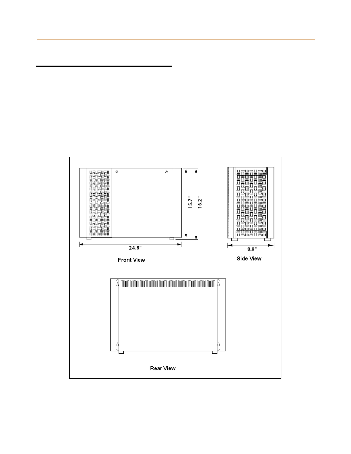
KSU Installation 3-5
Chapter 3 - System Installation
KSU Installation
The XTS Key Service Unit (KSU) consists of Cabinet 0 and optional Cabinets 1 and 2. The basic
exterior of the XTS System is shown in Figure 3-1 .
Mounting Cabinet 0
Cabinet 0 is a metal frame cabinet designed for wall mounting. Use the mounting template
provided with the Cabinet to mark the location for the screws to mount the Cabinet. The
Cabinet must NOT be mounted directly on a masonry or dry-wall surface; in this case a
wooden backboard is required. Refer to Figure 3-2 for the distance between mounting holes.
Figure 3-1: XTS Mounting Holes and Installation Layout
Page 40
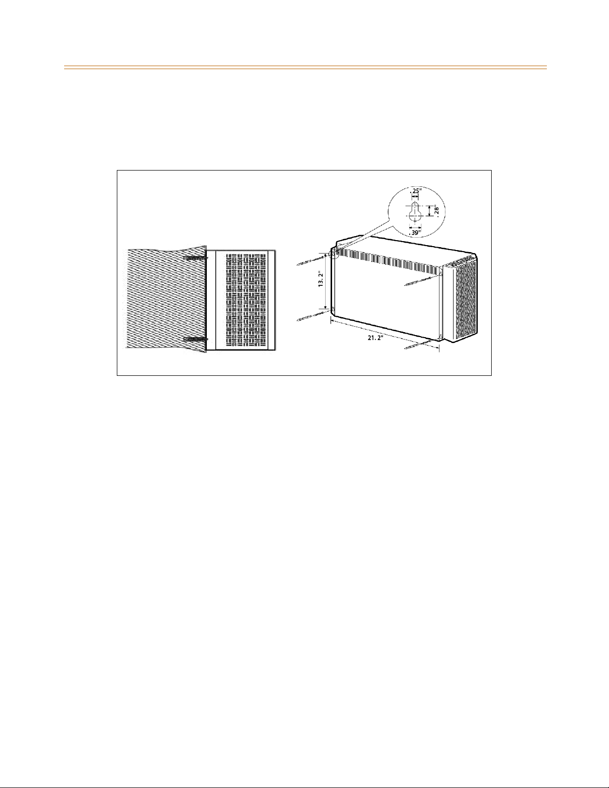
3-6 KSU Installation
Chapter 3 - System Installation
The Cabinet is mounted with four #10 or larger, 1 ½ inch or longer screws.
1. Drill pilot holes in the locations marked, insert the screws and tighten, leaving about ½
inch exposed.
2. Mount the Cabinet on the screws and tighten the screws securely.
Figure 3-2: Mounting XTS Cabinet
Mounting Cabinet 1 and Cabinet 2
The optional Cabinets include a metal housing designed for wall mount installation. Cabinet
1 is mounted above Cabinet 0 and Cabinet 2 is mounted above Cabinet 1.
1. Before mounting the optional Cabinets, remove the Interconnection Cover on the top
right side of Cabinet 0 and Cabinet 1 and on the bottom of Cabinet 1 and Cabinet 2.
2. Mount the optional Cabinet on the screws and tighten the screws securely.
3. Mount the 4 side brackets between the Cabinets.
4. Interconnection is achieved via a amphenol type connector. No cable is used to connect
the Cabinets together. Refer to Figure 3-3 .
Page 41
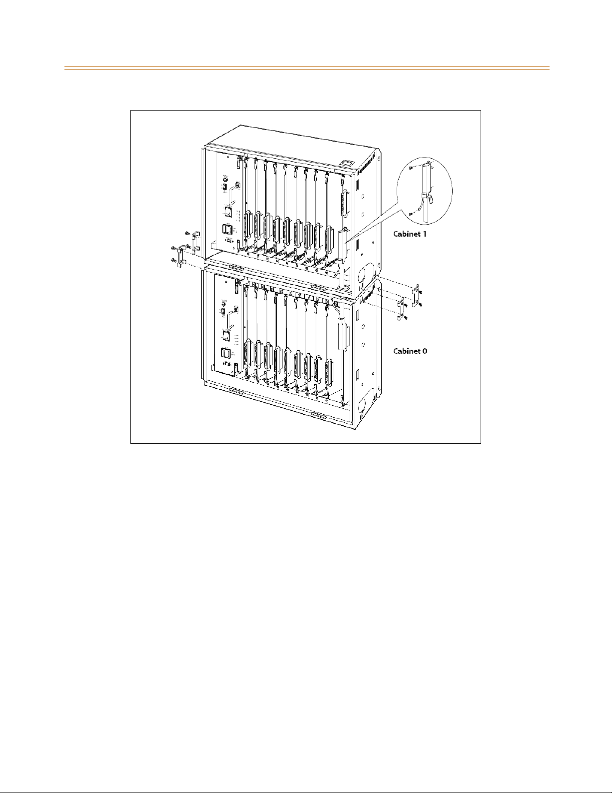
KSU Installation 3-7
Chapter 3 - System Installation
Figure 3-3: Connecting Cabinet 0 and Cabinet 1
Page 42
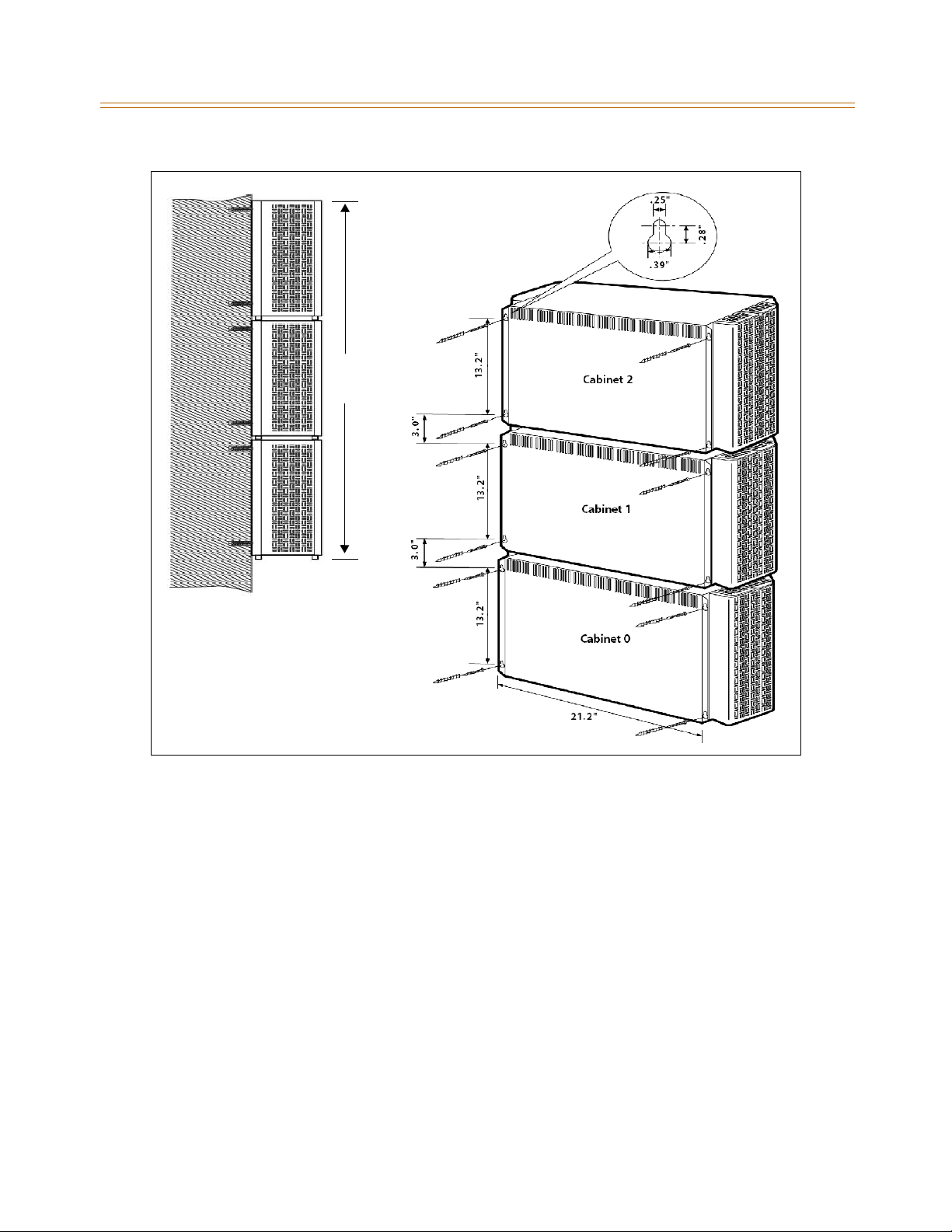
3-8 KSU Installation
Chapter 3 - System Installation
48.3”
Figure 3-4: Mounting Cabinets 0, 1, & 2
Page 43
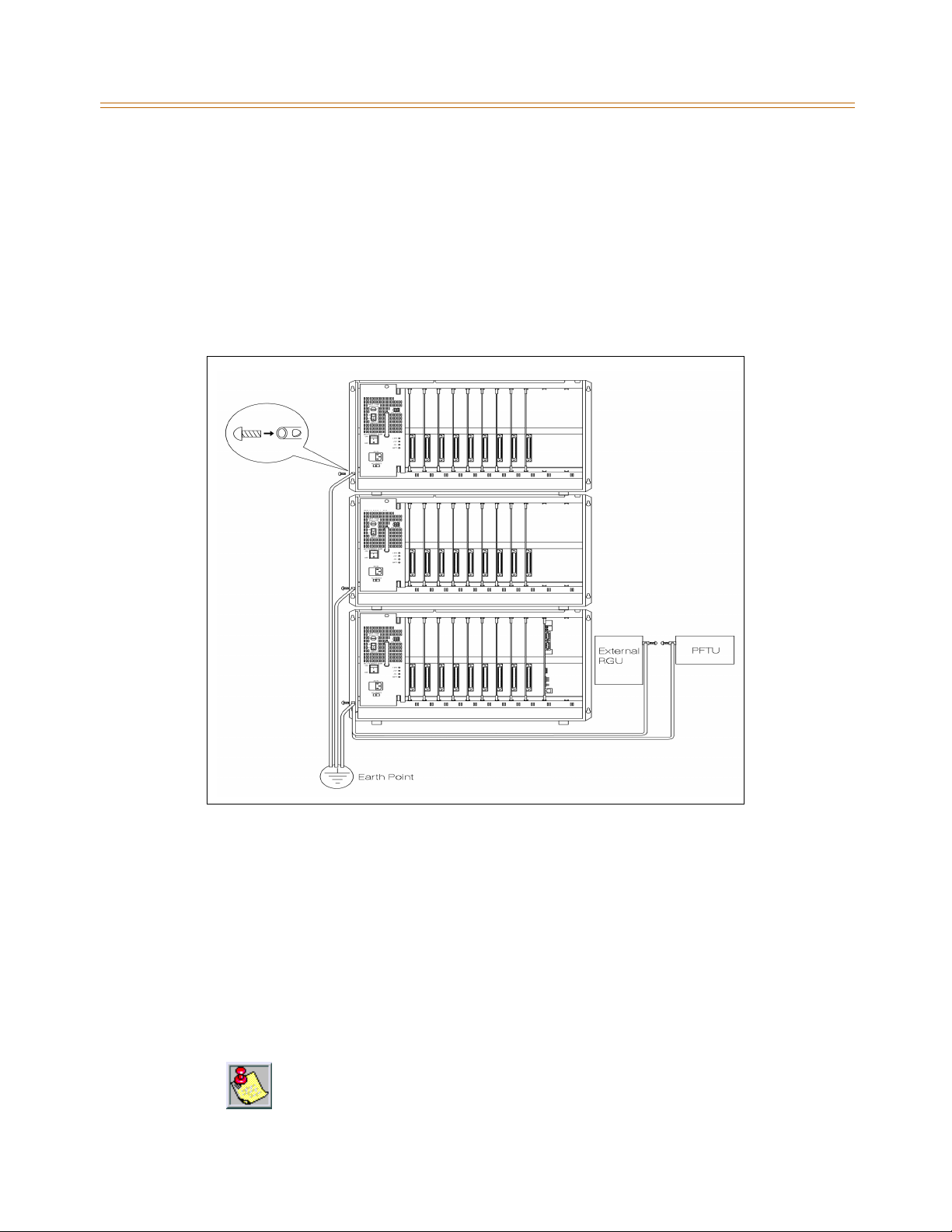
KSU Installation 3-9
Chapter 3 - System Installation
KSU Grounding
To ensure proper system operation and for safety purposes, a good earth ground is required.
A metallic cold water pipe usually provides a reliable ground. Carefully check that the pipe
does not contain insulated joints that could isolate the ground path. If insulated joints exist,
another earth ground source must be used or, if allowed, the joints may be bridged.
A #14 insulated AWG or larger copper wire should be used between the ground source and
the KSU. The wire should be kept as short as possible. It is recommended that the wire be no
longer than 25 feet.
Figure 3-5: Earth Cable between KSU and External RGU
Grounding Instructions
1. Remove about 1½ inches of insulation from both ends.
2. Attach one end of the wire to the Ground Lug on the lower left side of the Cabinet 0 by
inserting the wire under the lug screw and tightening the screw securely.
3. Attach the other end of the wire as appropriate to the ground source.
4. Take a DC resistance reading and an AC Volt reading between the chassis ground point
(cold water pipe) and AC ground (third wire AC ground).
The limit is 1V AC and 5 Ohms DC resistance. If a higher reading is obtained, choose a
differentchassisgroundpointandrepeatthisstepuntilasuitablegroundpointisfound.
Grounding to an electrical conduit is NOT considered a good ground!
Page 44

3-10 KSU Installation
Chapter 3 - System Installation
Power Line Surge Protection
The AC outlet should be equipped with an additional power line transient surge protection
device. Systems using such devices are more resistant to damage from power line surges
than unprotected systems. Power line surges often occur during switching operations and
especially during violent thunderstorm activity.
Protector Specifications -- Installation of a surge protector meeting these specifications
prevents or minimizes the damage resulting from power line surges.
The Isolation Transformer/Surge Protector shall be a 15 amp self-contained unit that
plugsintoastandardgrounded117VACwalloutlet.
The wall outlet must be designed to accept a 3-prong plug (2 parallel blades and ground
pin).
The protector should be fast operating and capable of protecting transients greater than
200 volts.
It is recommended that the AC outlet be equipped with an isolation transformer/
surge protection device that utilized MOV protection.
Lightning Protection
The system provides secondary protection per UL 1459 Specifications. Primary protection
circuitry is the installers responsibility and should be installed per the National Electric Code
(NEC).
KSU AC Power Plug
1. Before plugging the KSU power cord into the AC source, verify that the Power switch on
the AC/DC front panel is in the OFF position.
2. Plug the KSU power cord into the AC outlet and turn the AC/DC Power switch to ON. The
red/green LED on the PSUs should illuminate.
Page 45
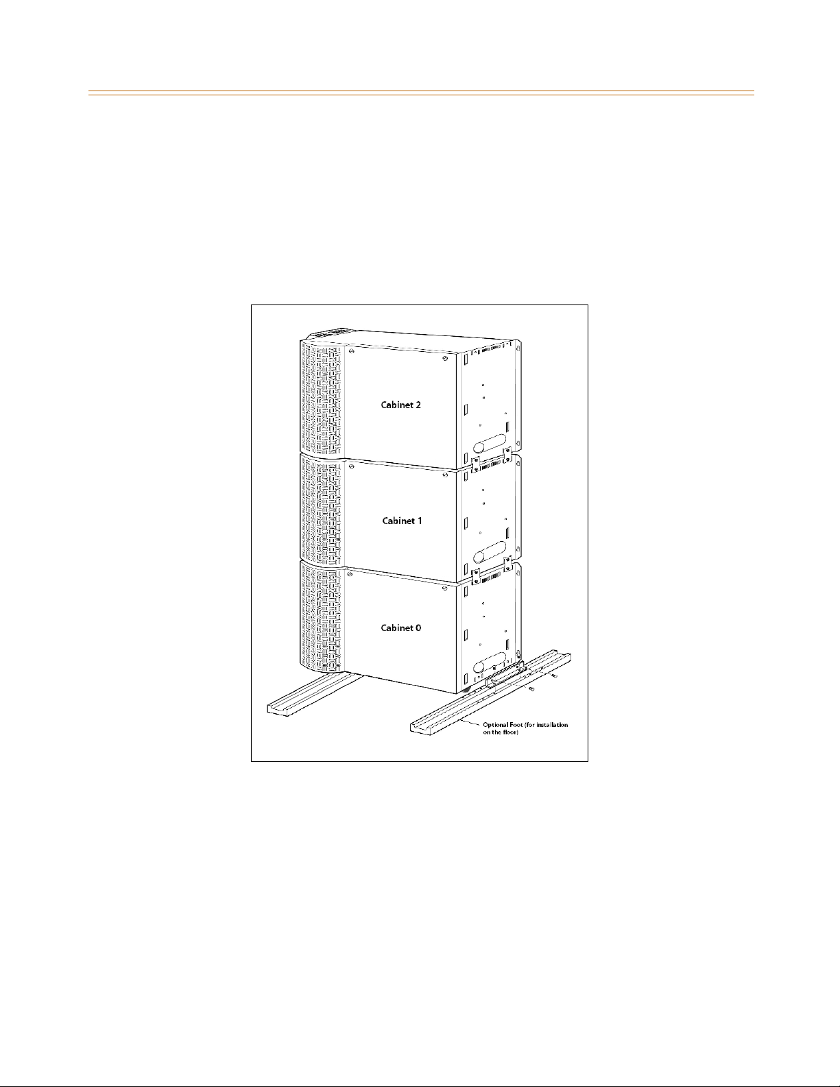
KSU Installation 3-11
Chapter 3 - System Installation
Optional Mounting Racks
Mounting Rack (Floor Model)
1. To install on the floor, use the optional foot.
2. To install the second or third Cabinets, use the screws provided to connect them as in
Figure 3-6 .
3. The installation position of the optional foot can be adjusted according to the
environment.
Figure 3-6: Mounting Rack
Page 46
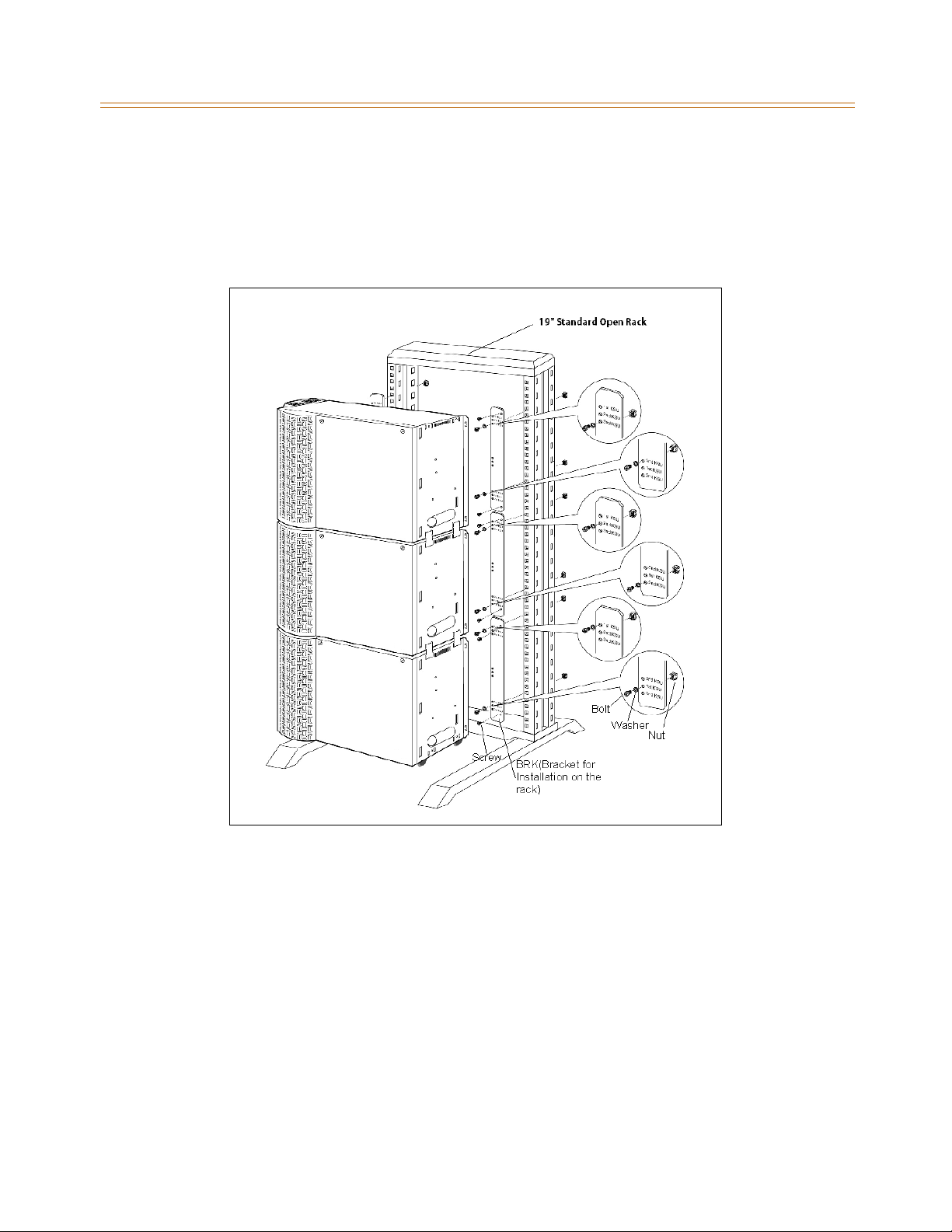
3-12 KSU Installation
Chapter 3 - System Installation
Optional Rack (Cabinet Model)
1. To mount rack, use the optional BRK (Bracket for installation on the rack). Usable rack is
the standard 19” rack. Any 19” open rack can be used.
2. After placing the rack on a flat floor, attach the Cabinet to the rack using provided BRK
with bolts and nuts on both sides as shown in Figure 3-7 .
Figure 3-7: Optional Rack
Page 47
Ring Generator Unit Installation 3-13
Chapter 3 - System Installation
Ring Generator Unit Installation
The Ring Generator Unit (RGU3) is needed if a SLIB is to be installed in a Cabinet. The RGU3
provides ring voltage and a Message Wait Source. A cable for connecting the RGU3 and KSU
is provided.
1. Mount the unit inside the Cabinet to the bottom side panel on the right with the two
screws provided.
2. Connect the unit to the backplane via CN14 connector (marked on PCB).
PowerSupplyUnitInstallation
The Power Supply Unit (PSU) provides power for the system boards and telephones,
converting AC voltage input to appropriate DC voltages.
Voltage Selector Switch
The PSU can operate from either 110/115 or 220/230 Volts AC based on the setting of the AC
SELECT switch on the lower front of the PSU.
If local AC is 115 volts, move the switch to the left position to display “115”.
If local AC is 230 volts, move the switch to the right position to display “230”.Defaultsetup
of the product is 115VAC.
Although, the PSU is equipped with power-line transient protection, an external
Power Line Surge Protector should be installed at the AC outlet to give additional
protection, especially during violent thunderstorm activity. Refer to
Protection”
.
“Lightning
The range of input voltage and the fuse rating of the PSU are as follows:
Table 3-1: Fuse Rating of the PSU
Position of
AC SELECT switch
115V 103V AC - 127V AC 8A @ 125V
230 206V AC - 254V AC 5A @ 250V
The Range of
Main Input Voltage
Fuse
Ratings
Power Capacity
The power capacity of the PSU is as follows:
+5V DC -5V DC +30V DC Battery Charging Current
10A 1.5A 8.4A 1A
Page 48
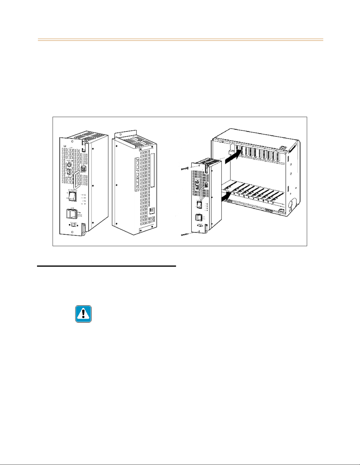
3-14 PCB Installation
Chapter 3 - System Installation
Before Installation -- Ensure that the AC plug connected to Cabinet 0 is NOT plugged into
the AC outlet.
1. Place the PSU in the left-most slot in Cabinet 0, aligning the card guides with the PSU PCB
and PSU frame flanges.
2. Slide the PSU into place using the injectors to seat the PSU fully in the Cabinet.
3. Then affix the PSU to the Cabinet with the two screws provided.
Figure 3-8: PSU Installation
PCB Installation
PCB Handling and General Installation
While it is possible to install and remove system cards with power on, it is not
recommended and could void your warranty.
The system PCBs contain digital circuitry which, while extremely reliable, can be
damaged by exposure to excessive static electricity. When handling PCBs, a grounded
wrist strap should be used to protect the boards from static discharges.
Inserting a PCB
1. Hold the PCB by the injector tabs and, with the components facing right, align the top
and bottom edge of the PCB in the card guides.
2. Slide the card into the system and use the injectors to seat the PCB firmly into the
backplane connector.
Page 49
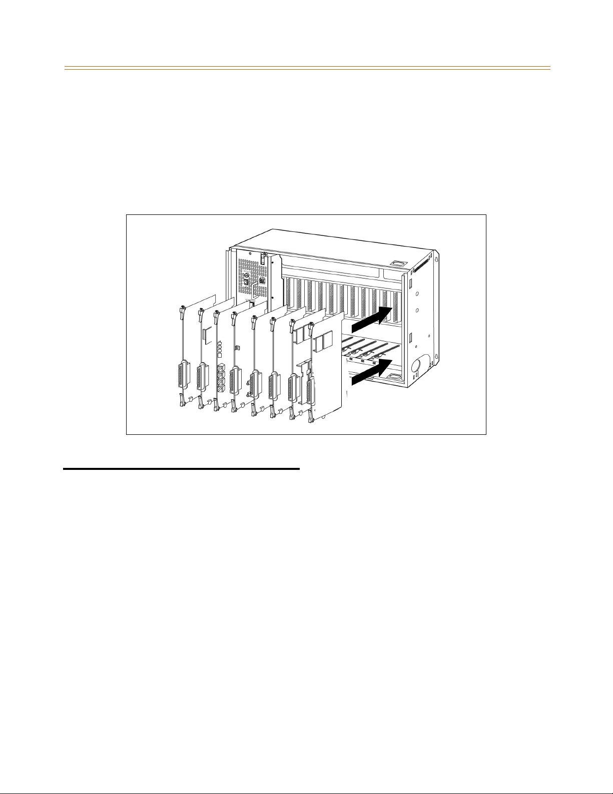
Main Processing Board Installation 3-15
Chapter 3 - System Installation
Removing a PCB
Reverse the Inserting a PCB procedure. Installation method of the PCB is shown in Figure 3-9 .
There is a ground tab located on the top and bottom of each PCB toward the front end of the
card.Thereisalsoagroundtablocatedtotherightofeachcardguideineachcabinet.Make
sure when the PCBs are inserted into the card guide and secured in their respective card slots,
that the ground tab on each card mates with the ground tab on each card guide. This ensures
a good ground potential to reduce RFI and EMI interference possibilities.
Figure 3-9: PCB Installation
Main Processing Board Installation
The Main Processing Board (MPB) is installed in the MPB PCB card slot (slot MPB) of Cabinet 0.
TheMPBmaybeequippedwith2add-onboards,aPMUforsoftwareprogramminganda
MODU for modem access to the system.
Lithium Battery
The MPB contains a lithium dry-cell to maintain memory and real-time clock functions. The
battery is soldered on the MPB and connected to the circuitry by the ON-OFF Dip Switch.
Make sure the switch is set to the ON position before installing the MPB.
Page 50
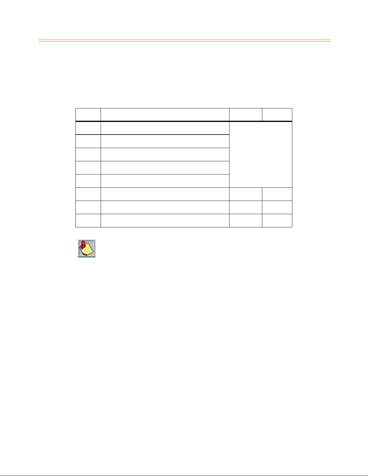
3-16 Main Processing Board Installation
Chapter 3 - System Installation
DIP Switch Positions (SW3)
The MPB also has an eight-position DIP switch, SW3. The default setting is: All ON position.
The function of each switch position is as follows:
Table 3-2: Dip Switch Settings (SW3)
Switch Function OFF ON
1N/A
2N/A
3N/A
4N/A
5N/A
6 Execute hardware tests at startup Disable Enable
7 Power up status trace of board (startup messages) Disable Enable
8 Database default on power up Disable Enable
Use extra care when removing RS-232 cables from the MPB or SIU boards. Hold the
MPB/MISB card in the card slot before removing the RS-232 cable. Failure to perform
this action may result in the MPB/MISB card being pulled from its slot.
RESERVED
leave these switches
in the ON position
Before programming the system, dip switch 8 (database default switch) should be placed in
the on position and power cycled off and on to initialize the system database to default. Once
the database has been initialized, switch 8 should be placed in the off position to protect the
database.
Page 51
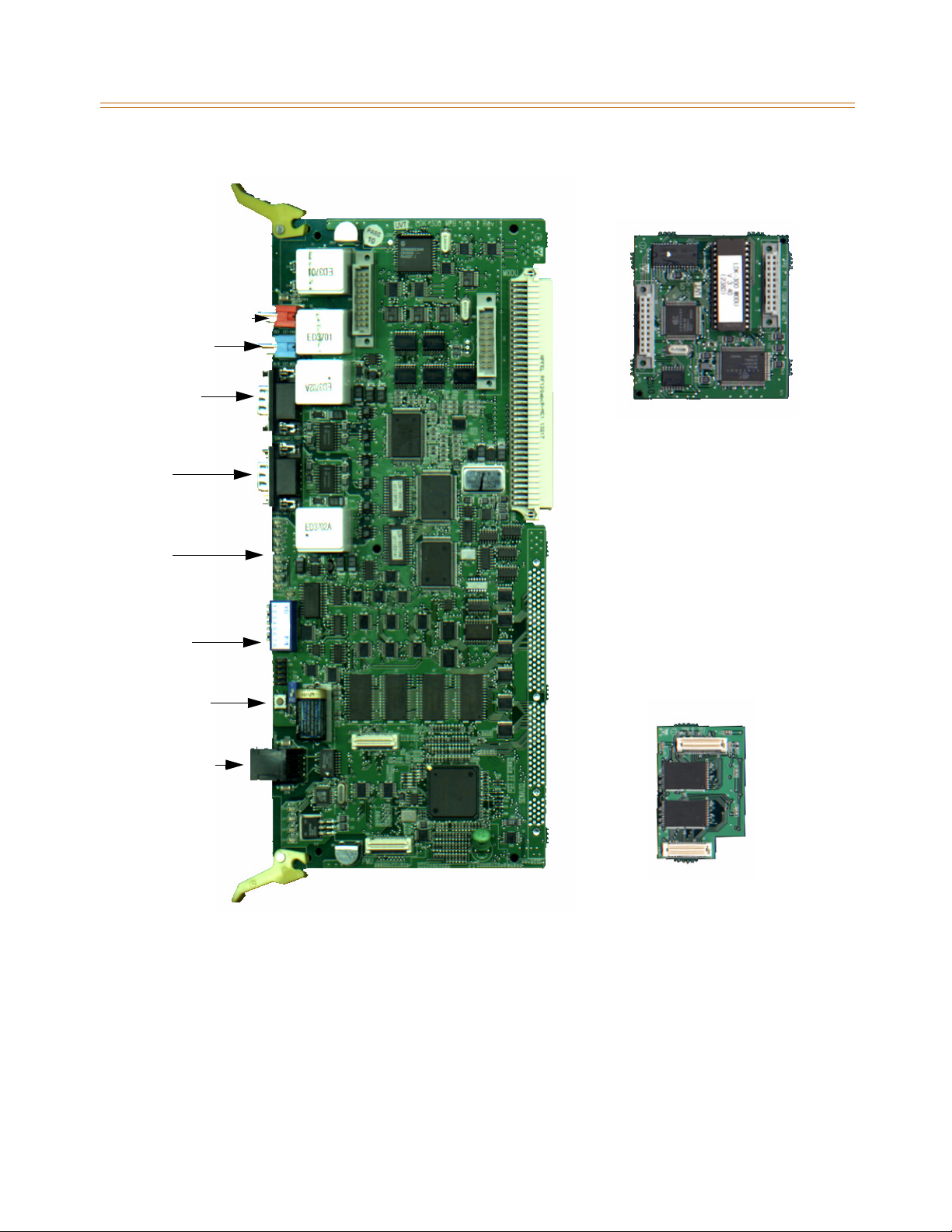
Main Processing Board Installation 3-17
Chapter 3 - System Installation
Paging (MPB2 only)
Music on Hold
(MPB2 only)
Port 5
(MPB2 only)
Port 1
MODU
LEDs
Database
Default Switch
Reset Button
Ethernet Jack
(MPB2 only -
Future U se)
Program Module Unit
The Program Module Unit (PMU) is installed on the MPB and contains the software used by
the system to control features and their function. Install the PMU before installing the MPB.
Port 2
PMU
Figure 3-10: MPB, PMU, and MODU Configuration
Page 52
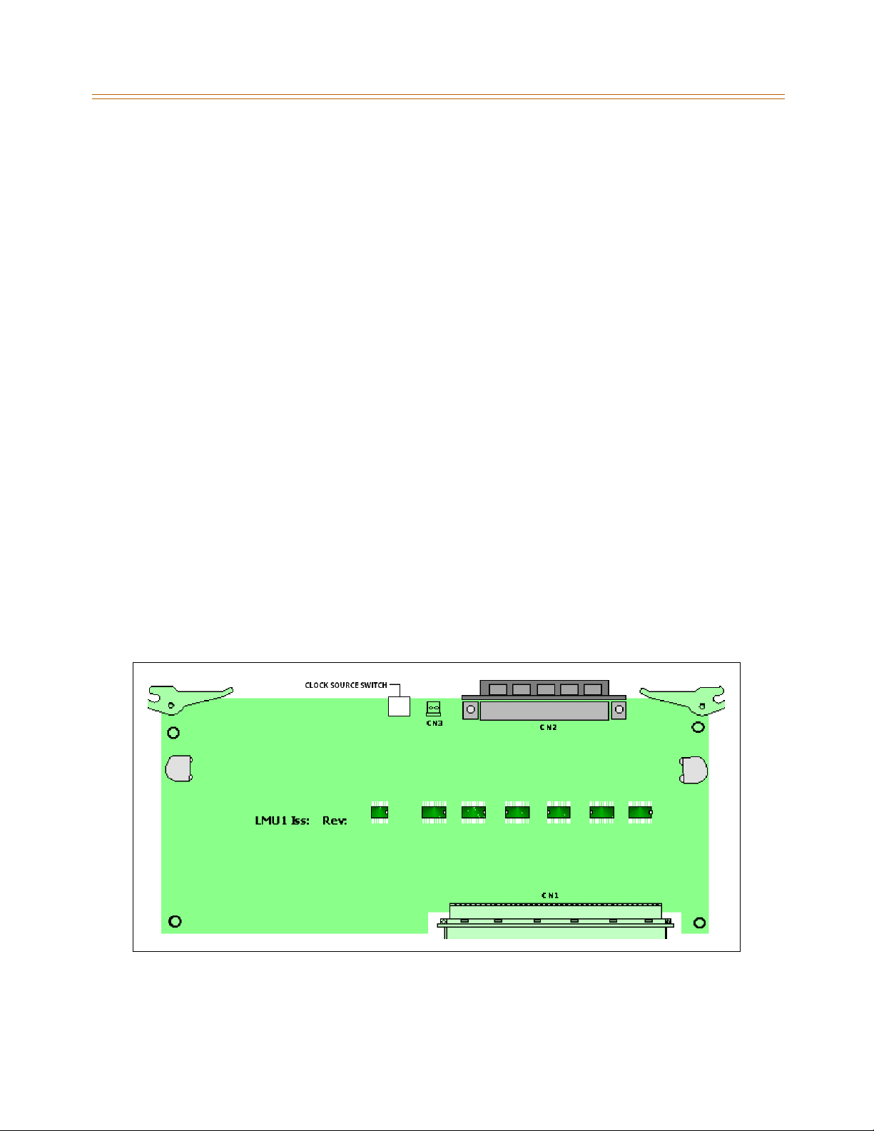
3-18 Main Processing Board Installation
Chapter 3 - System Installation
Installing the PMU
1. Unpack the PMU from its antistatic conductive bag.
2. LocatetheCN8andCN9connectorsontheMPB.LocatetheCN1andCN9connectorson
the PMU.
3. Position the PMU so that CN1 and CN2 align withCN8 and CN9 respectively on the MPB.
Push the PMU onto the respective connectors and make sure it seats properly.
Modem Unit
The Modem Unit (MODU) provides an asynchronous modem for access to the system
database and fault reporting features from a remote site. The module is optionally installed
on the MPB and incorporates a 19,200 bps modem. The modem may be connected to a
pre-selected CO Line through the system switching matrix.
Installing the MODU
1. Unpack the MODU from its antistatic conductive bag.
2. LocatetheCN1andCN2connectorsontheMPB.LocatetheCN1andCN2connectorson
the MODU.
3. Position the MODU so that CN2 and CN1 align with CN1 and CN2 respectively on the
MPB. Push the MODU onto the respective connectors and make sure it seats properly.
Link Module Unit
The Link Module Unit (LMU) provides a link between the Cabinets of the KSU. LMU1 must be
installed to connect Cabinet 0 to Cabinet 1. LMU2 is used to connect Cabinets 1 and 2. Signals
are transmitted or received via linked cable. Set the clock source switch of LMU1 to the up
position for T1 clock source chain and to the down position for PRI/BRI clock source chain.
Figure 3-11: LMU1 Board Configuration
Page 53
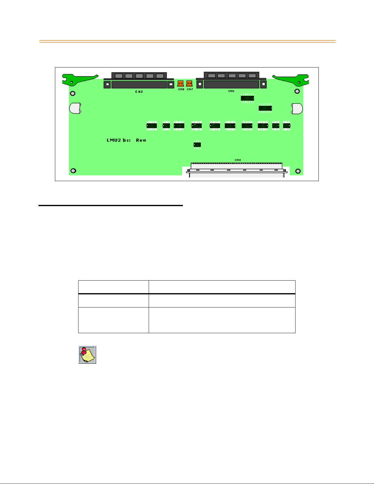
Miscellaneous Interface Unit Installation 3-19
Chapter 3 - System Installation
Figure 3-12: LMU2 Board Configuration
Miscellaneous Interface Unit Installation
The Miscellaneous Interface unit (MISB) contains an External Music port (MOH/BGM), an
External paging port, and four dry contacts. Optionally, the MISB is equipped with two serial
interface ports by installing the Serial Interface Unit (SIU) daughter board. The SIU should be
installed if more than two serial communication devices are to be connected to the system.
Table 3-3: MISB Connector Functions
Connectors / Switches Function
CN1 SIU Connection
RJ21X RJ21-type female connector (25-pair Amphenol) for
The MISB should be inserted into slot 8, Cabinet 0.
Use extra care when removing RS-232 cables from the MPB or SIU boards. Hold the
MPB/MISB card in the card slot before removing the RS-232 cable. Failure to perform
this action may result in the MPB/MISB card being pulled from its slot.
The MISB consists of:
External page ports from the amphenol connector on the front edge of the MISB. These
portsareconnectedtotransformers,providinga600ohmimpedance.
Music inputs from the amphenol connector on the front edge of the card.
Four independent relay contacts through the amphenol connector on the front edge of
the MISB. These contacts are controlled by software from entries in the system database.
Control signals are sent by the MPB. The output drives the relay coils, controlling the state
of the 1 amp, 24V relay contacts.
External Paging, External MOH, Relay contacts, and
Alarm Input
Page 54
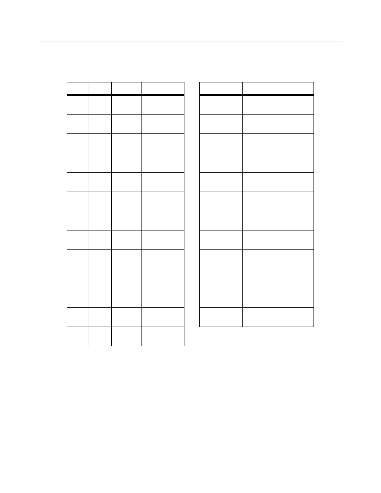
3-20 Miscellaneous Interface Unit Installation
Chapter 3 - System Installation
Table 3-4: MISB Wiring
Pair PIN # Color Description Pair PIN # Color Description
1261WH/BL
BL/WH
2272WH/OR
OR/WH
3283WH/GN
GN/WH
4294WH/BN
BN/WH
5305WH/SL
SL/WH
6316RD/BL
BL/RD
7327RD/OR
OR/RD
8338RD/GN
GN/RD
9349RD/BN
BN/RD
10 35
10
RD/SL
SL/RD
RELAY1R
RELAY1T
RELAY2R
RELAY2T
RELAY3R
RELAY3T
RELAY4R
RELAY4T
14 39
14
15 40
15
16 41
16
17 42
17
18 43
18
19 44
19
20 45
20
21 46
21
22 47
22
23 48
23
BK/BN
BN/BK
BK/SL
SL/BK
YL/BL
BL/YL
YL/OR
OR/YL
YL/GN
GN/YL
YL/BN
BN/YL
YL/SL
SL/YL
VI/BL
BL/VI
VI/OR
OR/VI
VI/GN
GN/VI
ALARM - R
ALARM - T
11 36
11
12 37
12
13 38
13
BK/BL
BL/BK
BK/OR
OR/BK
BK/GN
GN/BK
BGM/MOH1R
BGM/MOH1T
EXP1R
EXP1T
24 49
24
25 50
25
VI/BN
BN/VI
VI/SL
SL/VI
Page 55
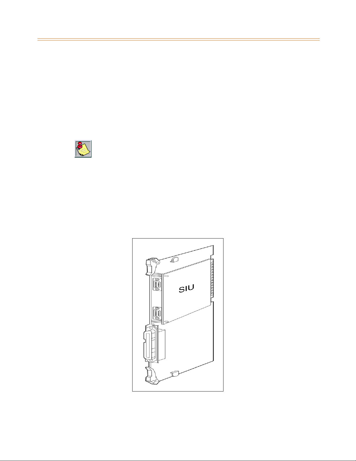
Miscellaneous Interface Unit Installation 3-21
Chapter 3 - System Installation
Serial Interface Unit
The Serial Interface Unit (SIU) board is used for SMDR printout and caller ID. The system
supports up to 4 Serial Interface circuits, 2 circuits on the MPB and an additional 2 circuits on
the SIU board (ports 3 and 4).
The following is a list of the system’soutput:
On-line SMDR
ACD
Caller ID
A SIU board can only be installed on the MISB.
Installing the SIU
1. Unpack the SIU from its antistatic conductive bag. There should also be a plastic bag with
two plastic standoffs and two metal screws.
2. Push the two standoffs into the holes on the SIU board.
3. Locate the CN1 connector and the two screw holes on the MISB.
4. Push the SIU board onto the CN1 connector ensuring that it seats correctly.
5. From the back side of the MISB board, insert the two metal screws into the holes and
tighten them into the bottom of each standoff to secure.
Figure 3-13: MISB & SIU Installation
Page 56
3-22 CO/PBX Connections
Chapter 3 - System Installation
CO/PBX Connections
There are four types of analog CO/PBX Line interface boards available. These boards include
the Loop Start CO Line Interface Boards (LCOB, LCOBE, and LCOBC) and the Direct Inward Dial
Interface Board (DIDB).
There are four types of digital CO/PBX Line interface boards available. These boards include
the T1IB, PRIB, BRIB, and VOIP card.
When using CO Lines as additional music inputs, keep in mind that the music source may
require a talk battery in series with either TIP or Ring. This talk battery boosts the signal level
sufficiently so that the CO Line interface can read the signal.
KSU
+
Battery
Figure 3-14: Talk Battery
Analog CO/PBX Line Interface Boards
Loop Start CO Interface Board
The Loop Start CO Interface Board (LCOB) supports up to eight (8) Loop Start CO Lines
(LCOB = 6 lines, LCOBE = 8 lines, LCOBC = 8 lines and Caller ID) and can be optionally
equipped with a DTMF Receiver Unit.
Each Interface contains ring and loop current detection circuits, Analog-to-Digital and
Digital-to-Analog conversions, and pulse and ground flash signaling circuit. The LCOB
contains LEDs that illuminate to indicate the in-use status of each CO line. The RJ21 type male
connector is mounted on the front edge of the LCOB for connecting to the CO lines.
Add-on Boards: DTRU for LCOB, DTRU4 for LCOBE and LCOBC
»
Installing the DTRU Module
DTRU to LCOB
1. Unpack the DTRU module from its antistatic conductive bag.
2. Locate the CN1 and CN2 connectors on the DTRU module.
3. Locate the CN1 and CN2 and the CN3 and CN4 connectors on the LCOB. Either pair can be
used to mount a DTRU. Use the second pair to mount a second DTRU.
4. Position the DTRU module so that either its:
CN1 aligns with CN2 and its CN2 aligns with the CN1 connector on the LCOB.
-or-
CN1 aligns with CN4 and its CN2 aligns with the CN3 connector on the LCOB.
5. Push the DTRU onto these connectors to seat it securely.
Music Source
-
Talk
Page 57
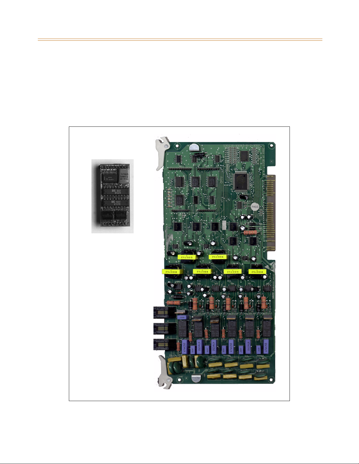
CO/PBX Connections 3-23
Chapter 3 - System Installation
DTRU4 to LCOBE or LCOBC
1. Unpack the DTRU4 module from its antistatic conductive bag.
2. Locate the CN1 and CN2 connectors on the DTRU4 module.
3. Locate the CN1 and CN2 connectors on the LCOBE.
4. Position the DTRU4 module so that the CN2 and CN1 connectors align with the CN1 and
CN2 connectors on the LCOB respectively.
5. Push the DTRU4 onto these connectors to seat it securely.
CON2
DTRU
CON1
CN1
CN2
CN3
CN4
Figure 3-15: LCOB Interface Board w/DTRU Installation
Page 58
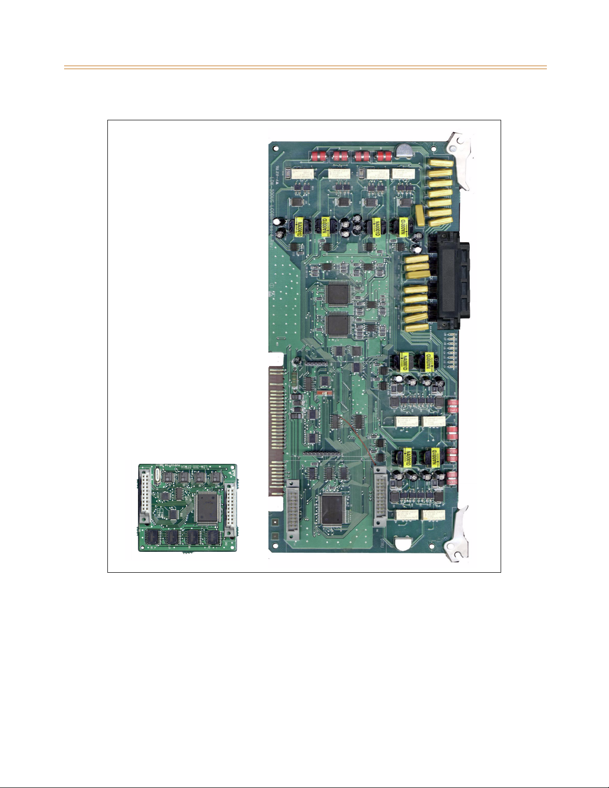
3-24 CO/PBX Connections
Chapter 3 - System Installation
CN1
4
U
R
T
D
CN2
CN3
Figure 3-16: LCOBE & LCOBC w/DTRU4 Installation
CN2
Page 59
CO/PBX Connections 3-25
Chapter 3 - System Installation
Table 3-5: LCOB Wiring
LCOB Connector
Connector Pin #
J2 3 Tip 1
2Ring1
4Tip2
1Ring2
J3 3 Tip 3
2Ring3
4Tip4
1Ring4
J4 3 Tip 5
2Ring5
4Tip6
1Ring6
LCOB
Designation
Page 60
3-26 CO/PBX Connections
Chapter 3 - System Installation
Pair PIN # Color Description Pair PIN # Color Description
1261WH/BL
BL/WH
2272WH/OR
OR/WH
3283WH/GN
GN/WH
4294WH/BN
BN/WH
5305WH/SL
SL/WH
6316RD/BL
BL/RD
7327RD/OR
OR/RD
8338RD/GN
GN/RD
9349RD/BN
BN/RD
10 35
10
RD/SL
SL/RD
Ring 1
Tip 1
Ring 2
Tip 2
Ring 3
Tip 3
Ring 4
Tip 4
Ring 5
Tip 5
Ring 6
Tip 6
Ring 7
Tip 7
Ring 8
Tip 8
LCOBE and LCOBC Station Ports
13 38
13
14 39
14
15 40
15
16 41
16
17 42
17
18 43
18
19 44
19
20 45
20
21 46
21
22 47
22
BK/GN
GN/BK
BK/BN
BN/BK
BK/SL
SL/BK
YL/BL
BL/YL
YL/OR
OR/YL
YL/GN
GN/YL
YL/BN
BN/YL
YL/SL
SL/YL
VI/BL
BL/VI
VI/OR
OR/VI
11 36
11
12 37
12
BK/BL
BL/BK
BK/OR
OR/BK
23 48
23
24 49
24
25 50
25
VI/GN
GN/VI
VI/BN
BN/VI
VI/SL
SL/VI
Page 61
CO/PBX Connections 3-27
Chapter 3 - System Installation
DID Interface Board
The Direct Inward Dial Interface Board (DIDB) provides four (4) analog DID CO interface ports.
The DIDB can be optionally equipped with a DTMF Receiver Unit (DTRU) daughter board to
detect DTMF tones.
If a DIDB is used, a DTRU is required; it does not necessarily have to be mounted on
the DIDB, but it must be installed within the system.
Installing the DTRU Module
1. Unpack the DTRU Module from its antistatic conductive bag.
2. Locate the CN1 and CN2 connectors on the DTRU module.
3. Locate the CN1 and CN2 connectors on the DIDB.
4. Position the DTRU module so that the CN2 and CN1 connectors match up with the CN1
and CN2 connectors on the LCOB respectively.
5. Push the DTRU module onto these connectors making sure it seats properly.
Connections
Connector Pin #
J3 3 Tip 1
2Ring1
1Tip2
4Ring2
J4 3 Tip 3
2Ring3
1Tip4
4Ring4
Designation
Page 62
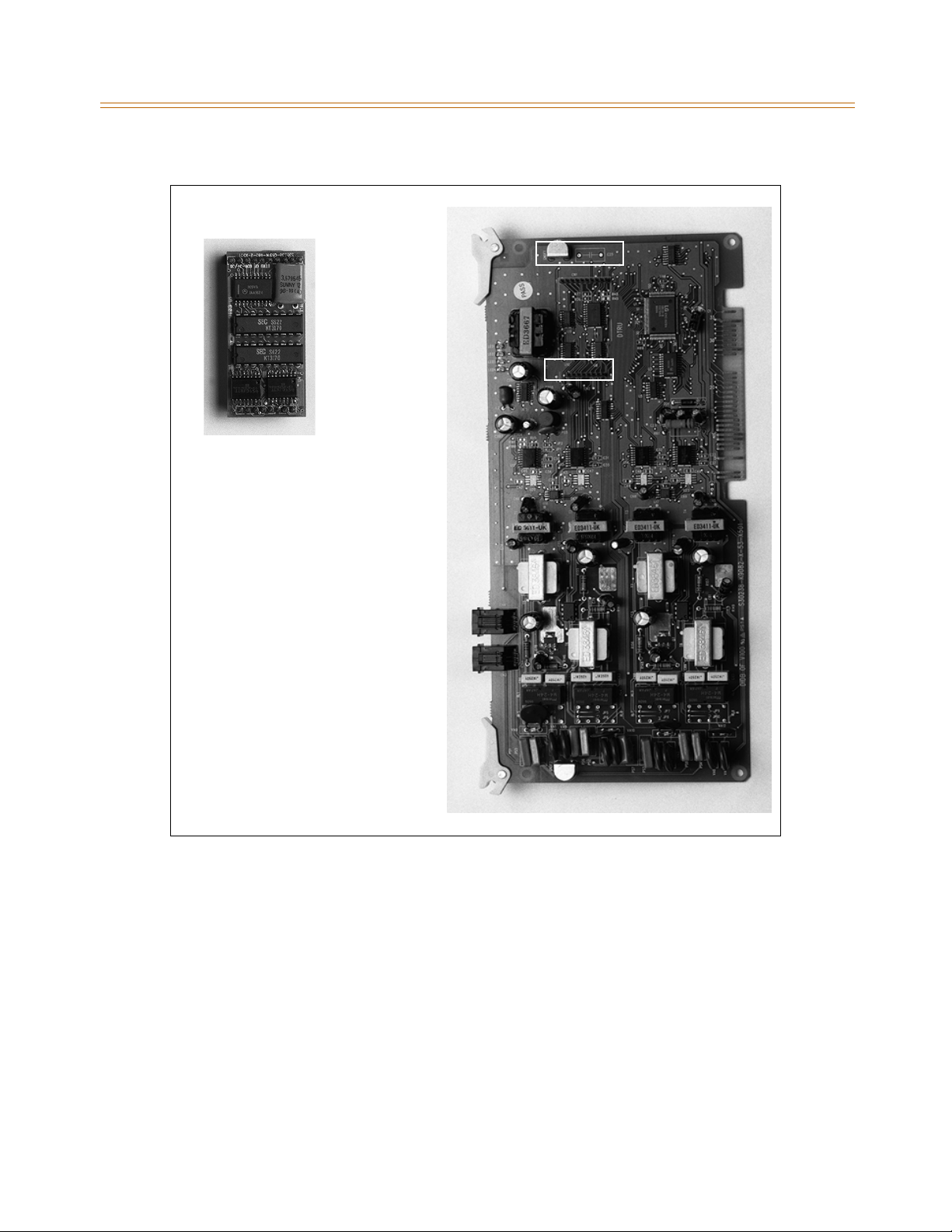
3-28 CO/PBX Connections
Chapter 3 - System Installation
CON2
CN1
DTRU
CN2
CON1
Figure 3-17: DIDB w/DTRU Installation
Digital CO/PBX Line Interface Boards
Digital CO/PBX line interface boards include the T1 interface board (T1IB), primary rate
interface board (PRIB), basic rate interface board (BRIB), and Voice over internet protocol
(VOIP) card.
T-1 Interface Board
The T-1 Interface Board (T1IB) provides the T-1 (1.544Mbps, 24-Voice Channel) digital
interface circuit, control circuitry, and synchronous clock control circuits. DTMF tone
detection units can be installed optionally on the T1IB. The T1IB has 8 LEDs on the front edge
of the PCB which indicates errors of T-1 line, in-use status, and synchronous clock enable
status.
Page 63
CO/PBX Connections 3-29
Chapter 3 - System Installation
Table 3-6: T-1 Board LEDs
LED # Meaning Function
1 IN USE At least one of the 24 circuits is in use.
2 RED T1IB is in Red alarm due to any alarm.
3 H/W TEST Normal call processing is not available.
4 BLUE. T1IB has detected RX_BLUE alarm.
5 YELLOW T1IB has detected RX_YELLOW alarm.
6 OOF T1IB is Out of Frame synchronization.
7 RCL T1IB receives Carrier Loss (unplugged from the cable)
8 CLOCK Clock Enable/Disable
The T1IB contains 2 switches (SW1 and SW3) and 3 connectors (CN1, CN2 and CN3). The clock
selection switch is used for control synchronous clock. The Line Build-Out switch is controlled
by distance between the XTS Systems and a CSU and SW1 #4 is used for loopback control.
The clock control cable should be connected by a daisy-chain method when more than one
T1IB board is installed. When the clock control cable of the T1IB is connected by daisy-chain
method, the clock selection switch of the first T1IB must be placed in the Enable position and
the other board should be placed in the Disable position. The Line Build-Out switch must be
selected by distance between the XTS System and a CSU and the switch selection as indicated
in the following chart. If the CSU is located near the KSU, all LBO switches should be ON.
The SW1 switch #4 of the Line Build-Out switch is used for LoopBack control. Its switch is used
only for hardware test and must be placed in the ON position for normal operation.
Table 3-7: T-1 Ordering Information
T-1 Ordering Information
Ringer Equivalent Number 6.0P
Facility Line Interface 04DU9-B
Jack Type RJ45
Table 3-8: T-1 Switch Positions
Distance
1234
0 to 133 feet on on on on
Switch #
133 to 266 feet off on on on
266 to 399 feet on off on on
399 to 533 feet off off on on
533 to 655 feet on on off on
Page 64
3-30 CO/PBX Connections
Chapter 3 - System Installation
This board supports standard D4 framing format with robbed bit signaling. Extended
Super Frame (ESF) format is also supported.
The board requires an external CSU unit.
The T1 board can accept two DTRU4 units in a daughter board type arrangement. Each
unit has 4 DTMF Receivers installed on it.
The board has a 15-pin D Sub connector for connection to a CSU unit.
The card ejector tabs are color coded white.
Functionality Description
AutomaticNumberIdentification(ANI)information from the carrier is treated exactly
the same as an inbound ICLID (Caller ID) number. Calls can be routed, placed in the
Unanswered Call Table, sent out to the CTI Module port on a keyset, and run through the
Number To Name Translation Table. The XTS system provides call progress tones in the
same manner as ICLID.
Dialed Number Identification Service (DNIS) information from the carrier is treated
using DID line rules. DNIS calls are routed based on the DID Routing Table.
ANI/DNIS is a combined format, where the system waits for the ANI/DNIS information
from the carrier. When it is received, the system routes the call using ICLID processing. If
this information is not found in the ICLID Route Tables, the DNIS information is compared
to the DID table for a match. The call is then routed based on the DID tables. If a match is
not found on either the ANI or DNIS number, the call is routed based on normal CO line
operation (CO Ringing Assignments).
The following table summarizes the operation of the system.
Table 3-9: Call Routing Criteria
ANI DNIS Operation
N N Calls routed based on normal CO operation (CO Ring Assignments.
N Y Calls routed based on DID tables with DID operation.
Y N Calls routed based on ICLID routing and ICLID operation.
Y* Y Calls routed on ICLID first, if no route is found, the DNIS digits are
*If both ANI and DNIS calls are routed -- the following table summarizes what is displayed at the phone.
The T-1 card accepts ANI/DNIS information in a DTMF format only. Some carriers do
not provide ANI or ANI/DNIS in a DTMF format. Consult your local carrier for available
options.
compared to the DID table. If no route is found in the DID table the
call is routed based on CO line Ringing Assignments.
Page 65
CO/PBX Connections 3-31
Chapter 3 - System Installation
Table 3-10: Call Routing Display Format
Route
Found
Type of
Display
Format
ICLID ICLID ANInumberplacedinthe14-characternumberfield,the
DNIS number followed by the name programmed in ICLID
translation table placed in the 24-character name field.
DID ICLID ANI number placed in 14-character number field. DNIS
number followed by programmed name from the DID
tables in 24-character name field.
NONE ICLID ANI number placed in 14-character number field and the
DNIS number is placed in the 24-character name field.
T-1 Ordering Information: When ordering a T-1 circuit from a carrier, request either D4
framing and Alternate Mark Inversion (AMI) Line coding using the superframe (SF) or the
Extended Superframe (ESF-B8ZS) format. The following are additional ordering information
specifications:
Table3-11:T-1OrderingSpecifications
If ordering…
ANI/DNIS/
DID/TIE
Circuit Information 2 wire 2 wire
Loop Start/
Ground Start Signaling*
Supervisory Signaling TIE Loop or Ground
Address Signaling DTMF DTMF
Start Dial Indicator Wink Start Dial Tone
* ANI/DNIS not available on Loop/Ground start signaling. If Loop Start signaling protocol is ordered,
the Central Office does not provide Disconnect Supervision. However if TIE signaling protocol is
ordered,
disconnect supervision is provided. The switching equipment processes DNIS numbers received from
the T-1 circuit depending on the trunk simulation.
Table 3-12: Telco to T1IB Interconnect Diagram - Pin Connections
Telco T1IB
RJ45 DB15 Female Pin #
1--> <--9
2--> <--1
4--> <-- 11
5--> <--3
Installing the DTRU4 Modules
1. Unpack the DTRU4 modules from their antistatic conductive bags.
2. Locate the CN1 and CN2 connectors on the DTRU4 modules.
3. Locate the CN4, CN5, CN8 and CN9 connectors on the T1IB.
Page 66
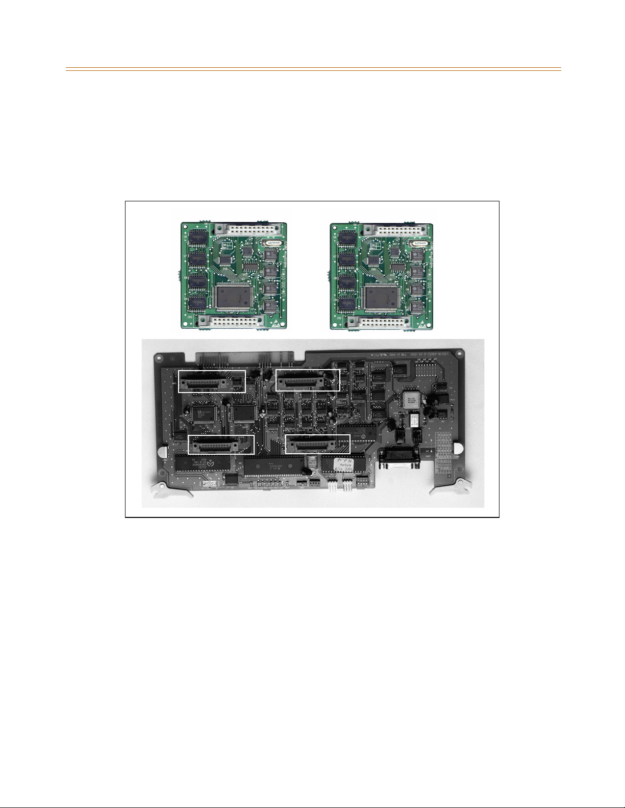
3-32 CO/PBX Connections
Chapter 3 - System Installation
4. Position one of the DTRU4 modules so that the CN2 and CN1 connectors align with the
CN8 and CN9 connectors on the T1IB respectively.
5. Push the DTRU4 module onto these connectors to seat it securely.
6. Position the second DTRU4 module so that the CN2 and CN1 connectors align with the
CN4 and CN5 connectors on the T1IB respectively.
7. Push the DTRU4 module onto these connectors to seat it securely.
CN9
D
CN8
T
CN2
U
R
CN1
CN2
4
CN5
CN4
4
U
R
T
D
CN1
Figure 3-18: T1IB w/DTRU4 Module Installation
Primary Rate Interface Board
The Primary Rate Interface Board (PRIB) provides one Primary Rate Interface circuit. Each
circuit contains 23 bearer and one data channel (23B+D). When a PRIB card is programmed
into the XTS system, the system interprets all B channels as trunks. Thus, one PRIB which
contains 23B+D circuits provides 23 line appearances to the XTS system. The PRIB card uses
24 time slots when installed. A feature of Flash 24 programming allows for partial signaling
over T1IBs or PRIBs. This allows you to limit the amount of time slots used per card to four, or
multiples of four up to 20.
The PRIB must usually be used in conjunction with a Channel Service Unit (CSU). Connection
is made via a DB15 from the PRIB to the CSU. When networking systems that are less than
50 feet apart, no CSU is required.
Page 67
CO/PBX Connections 3-33
Chapter 3 - System Installation
The PRIB accepts two DTRU4 boards.
Table 3-13: PRIB Ordering Information
PRIB Ordering Information
Framing ESF
Line Coding B8Zs
National ISDN NI-2
Table 3-14: Telco to PRIB Interconnect Diagram - Pin Connections
Telco PRIB
RJ45 DB15 Female Pin #
1--> <--9
2--> <--1
4--> <-- 11
5--> <--3
Installation
1. Insert the PRIB card(s) into the desired card slot.
2. If installing a single PRIB, set SW2 to the ON position.
If multiple PRIBs are being installed, set SW2 to the ON position on the first card and SW2
on all other cards to the OFF position.
ThePRIBcomeswithaclockcable.ThiscableisusedwhenmultiplePRIBand/ordigital
trunk cards are to be installed in the system. The clock cable is supplied with each PRIB.
3. Connect the DB15 cable from the PRIB to the channel service unit (CSU).
4. Connect the network cable from the channel service unit to the network.
5. Refer to ISDN and T1 Clocking (later in this section) for clarification on clocking and
cabling when combining BRIB, PRIB, and T1 cards in one Cabinet.
Installing the DTRU4 Modules
1. Unpack the DTRU4 modules from their antistatic conductive bags.
2. Locate the CN1 and CN2 connectors on the DTRU4 modules.
3. Locate the CN16, CN17, CN18 and CN19 connectors on the PRIB.
4. Position one of the DTRU4 modules so that the CN2 and CN1 connectors align with the
CN17 and CN16 connectors on the PRIB respectively.
5. Push the DTRU4 module onto these connectors to seat it securely.
6. Position the second DTRU4 module so that the CN2 and CN1 connectors align with the
CN19 and CN18 connectors on the PRIB respectively.
Page 68
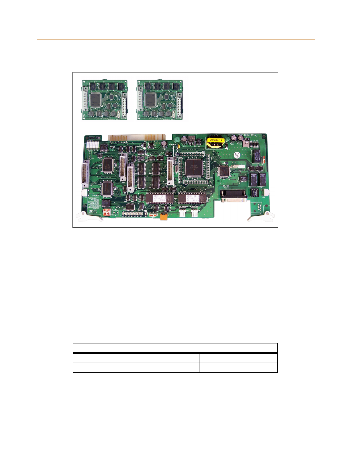
3-34 CO/PBX Connections
Chapter 3 - System Installation
7. Push the DTRU4 module onto these connectors to seat it securely.
CN2
CN17
4
U
R
T
D
Figure 3-19: PRIB w/DTRU4 Module Installation
CN2
CN1
CN16
CN19
4
U
R
T
D
CN1
CN18
ThePRIBisofferedasastand-alonecardorasakitwhichincludesthePRIB,CSU,andcables.
Basic Rate Interface Board
The Basic Rate Interface Board (BRIB) interface provides four Basic Rate Interface circuits. Each
circuit is comprised of two bearer (64Kbps each) and one data (16Kbps) channels (2B+D).
When a BRIB is programmed into the XTS system, the system interprets all B channels as
trunks. Thus, one BRIB which contains four 2B+D circuits provides eight line appearances to
the XTS system.
The BRIB uses the U interface of the BRI standard. Connection to the network is made via RJ45
connectors on the front edge of the board. No CSU device is required to connect to the
central office. The BRIB card uses eight time slots when installed.
Table 3-15: BRIB Ordering Information
BRIB Ordering Information
Ordering Code Capability P
National ISDN NI-1
Page 69
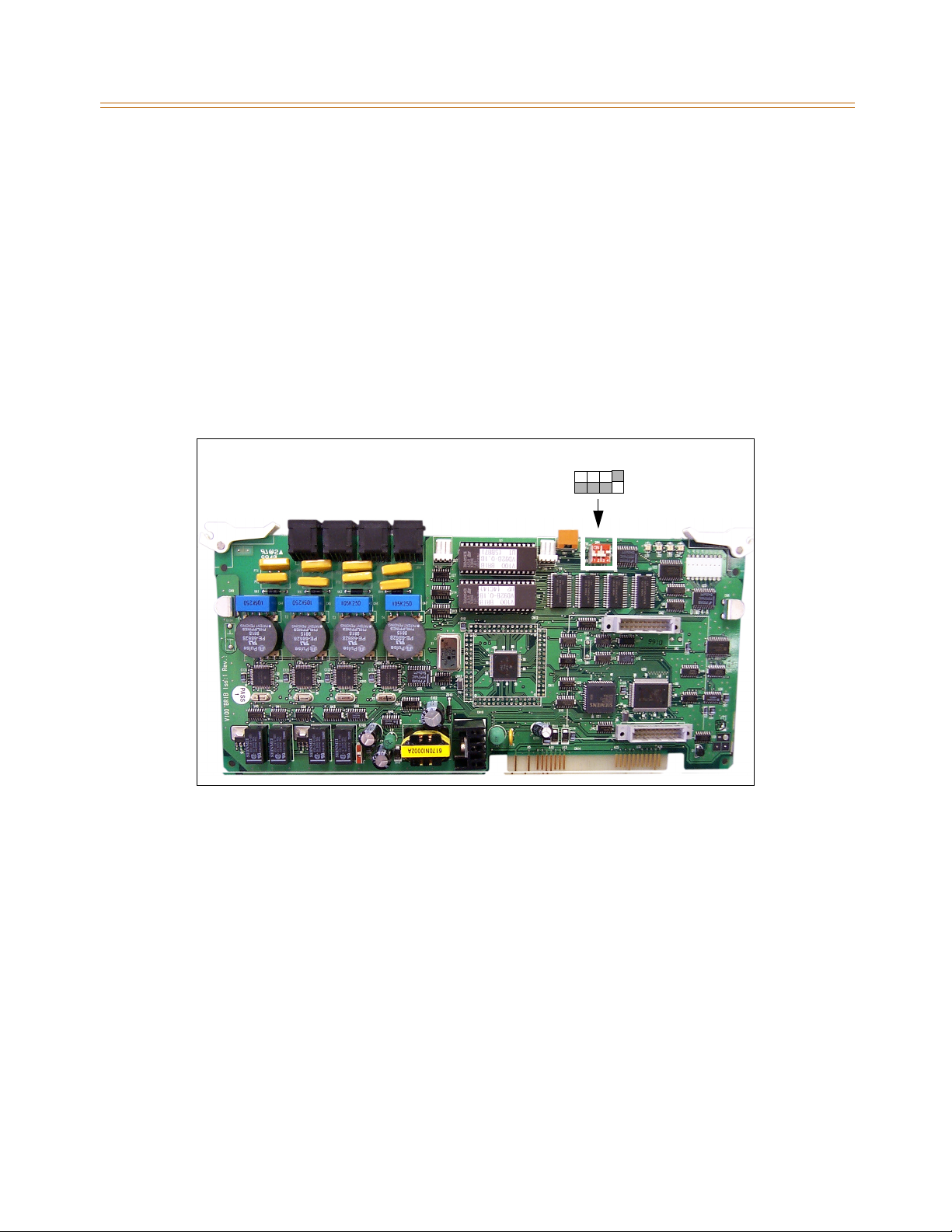
CO/PBX Connections 3-35
Chapter 3 - System Installation
Installation
1. Insert the BRIB card(s) into the desired card slot. Up to seven BRIB cards can be installed in
an XTS Cabinet, with a maximum of 18 per system.
If installing a single BRIB, set switch 4 on SW2 to the ON position.
If multiple BRIB cards are being installed, set switch 4 on SW2 to the ON position on
the first card and switch 4 on SW2 on all other cards to the OFF position. Switch 4 on
SW2 determines if the board is the Master Clock source for any digital trunk cards in
the system. Only one Master Source must be enabled in the system.
If installing a BRIB in a system that also has T1 or PRIB boards, use either the T1 or PRIB
card as the Master Clock and set all BRIB SW2 switch 4s to OFF.
2. Refer to ISDN and T1 Clocking (later in this section) for clarification on clocking and
cabling when combining BRIB, PRIB, and T1 cards in one Cabinet.
2
3
SW2 SWITCHES:
41
ON
OFF
Figure 3-20: BRIB (Basic Rate Interface Board)
Voice Over the Internet Protocol Card
The Voice Over the Internet Protocol (VOIP) card provides up to eight lines per card (two lines
per installed VOIP module). The VOIP card allows bi-directional voice communication to
other H.323 Revision 2 compatible devices via an IP network such as an internal Local Area
Network (LAN), the Internet, or a Wide Area Network (WAN) using the Ethernet Interface. It
also provides four-digit dialing.
The VoIP card uses Transmission Control Protocol/Internet Protocol (TCP/IP) for packet
delivery over an IP network. Additional standards and protocols are used to provide DTMF,
voice processing, and compression.
The VoIP card can accommodate up to four VoIP modules. Each VoIP module provides
capability for two ports, resulting in a maximum of eight ports when all four modules are
installed.
Installation
Insert the VoIP card into the desired slot.
Page 70
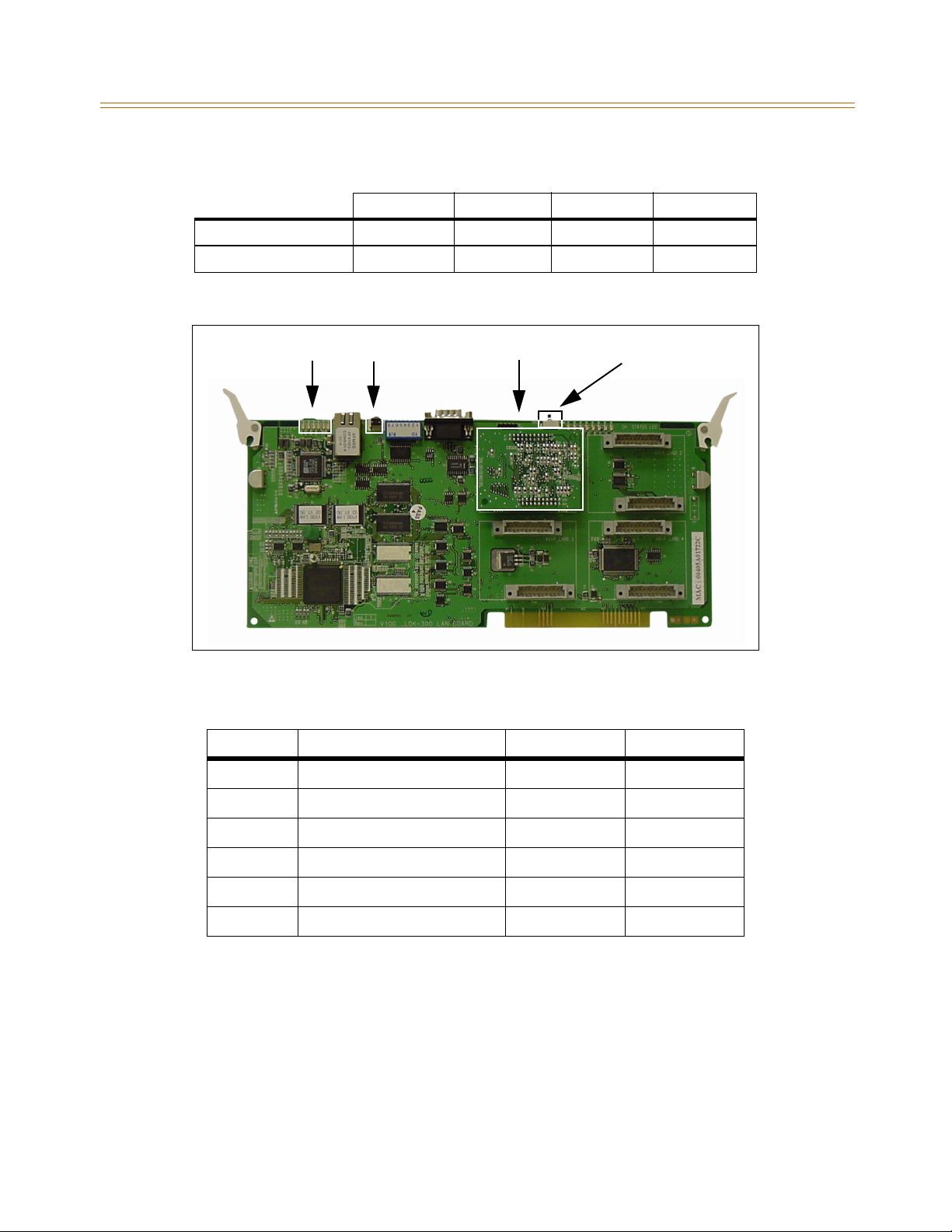
3-36 CO/PBX Connections
Chapter 3 - System Installation
Table 3-16: Bandwidths
2 Ports 4 Ports 6 Ports 8 Ports
Recommended
Minimum
LEDs
512K 640K T1 T1
256K 256K 512K 512K
Note: Assumes network latency is below 120 ms
VoIP Card Reset Button
VoIP Module
Service Switch
Figure 3-21: VoIP Card with One VoIP Module Installed
Table 3-17: VoIP Card LED Indications
LED Indication ON OFF
09 LAN Speed 100 Mbps 10 Mbps
10 Rx Status Active Idle
11 Tx Status Active Idle
12 Link Status Valid Link No Link
13 Collision Status Collision No Collision
14 Half/Full Duplex Mode Half Duplex Full Duplex
Note: LED 09 is closest to the Ethernet port.
Page 71
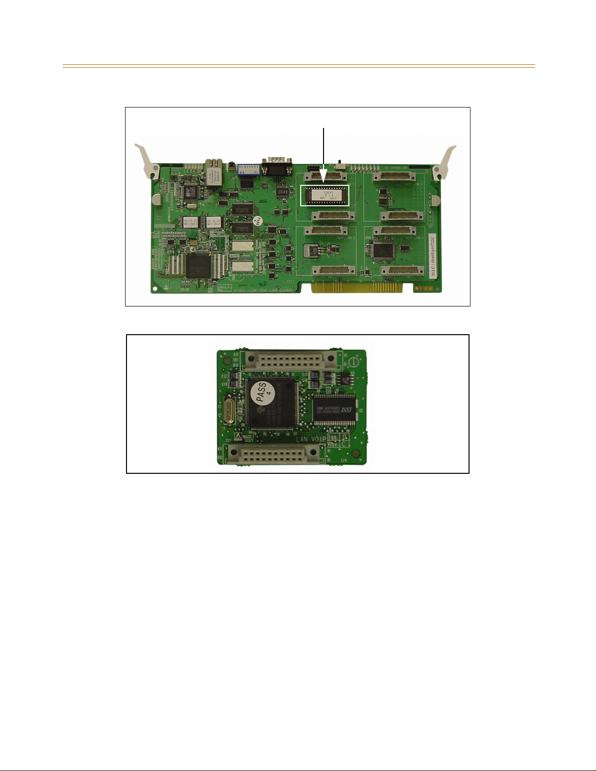
CO/PBX Connections 3-37
Chapter 3 - System Installation
VoIP Firmware
Figure 3-22: VoIP Card - No VoIP Modules Installed
Figure 3-23: Connection Side of VoIP Module (Closeup)
Page 72
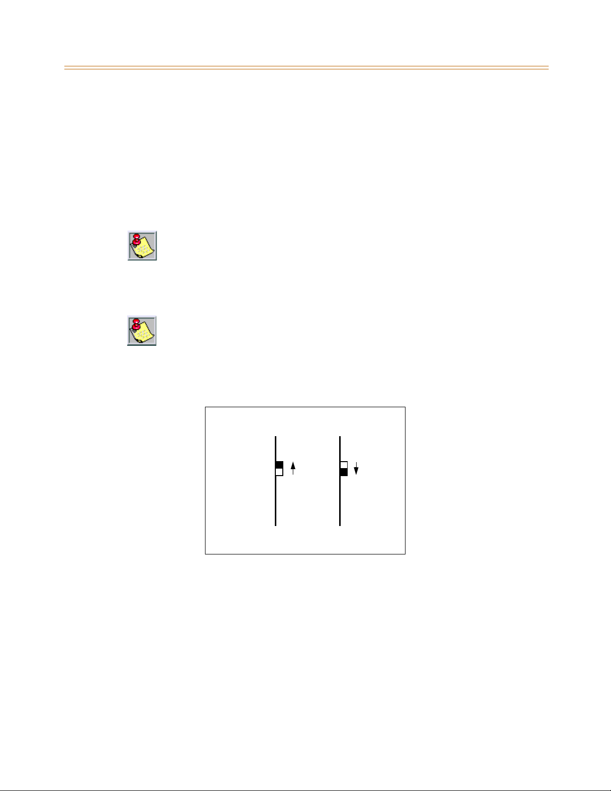
3-38 CO/PBX Connections
Chapter 3 - System Installation
ISDN and T1 Clocking
When combining BRIB, PRIB, and T1 cards in one KSU, specific settings and cabling are
important for proper clocking. The Phase Lock Loop circuitry within the MPB synchronizes
the clocking from the Central Office to the clocking of the KSU. Popping, crackling, dropped
calls, and one-way transmission are usually attributed to the clocking not being synchronized
correctly.
Set the clock source switch of LMU1 to the up position for T1 clock source chain and to the
down position for PRI/BRI clock source chain.
If using a point-to-point connection (e.g., networking), do not connectclock cable to
a point-to-point circuit.
Examples - Settings and Cabling
The following examples clarify the clocking and cabling for these cards:
Whentheswitchisinthe“up” position, it should beconsidered “ON”.Whentheswitch
is in the “down” position, it should be considered “OFF”.
The cable connection follows the same logic - “up” is clock outside (ON) and “down”
is clockinside (OFF). ON means that clocking is coming fromoutside the KSU and OFF
means that clocking is coming from inside the KSU.
(1) T1IB and (1)PRIB
T1IB PRIB
SW3 On SW2 Off
If both cards in a phone switch are connected to a telephone company clock (not point-topoint T1), put the T1 clock switch in the enable position (UP) to allow it to receive clocking
from the telephone company directly, and do not install the clock cable.
Set the PRIB clock switch in the disable position (OFF), which allows the PRIB to synchronize
its timing off of the backplane (from the T1 clocking). If the T1 is a point-to-point T1, set the
PRIB in the enable position (ON), the T1 in the disable position (OFF), and do not install the
clock cable.
Page 73
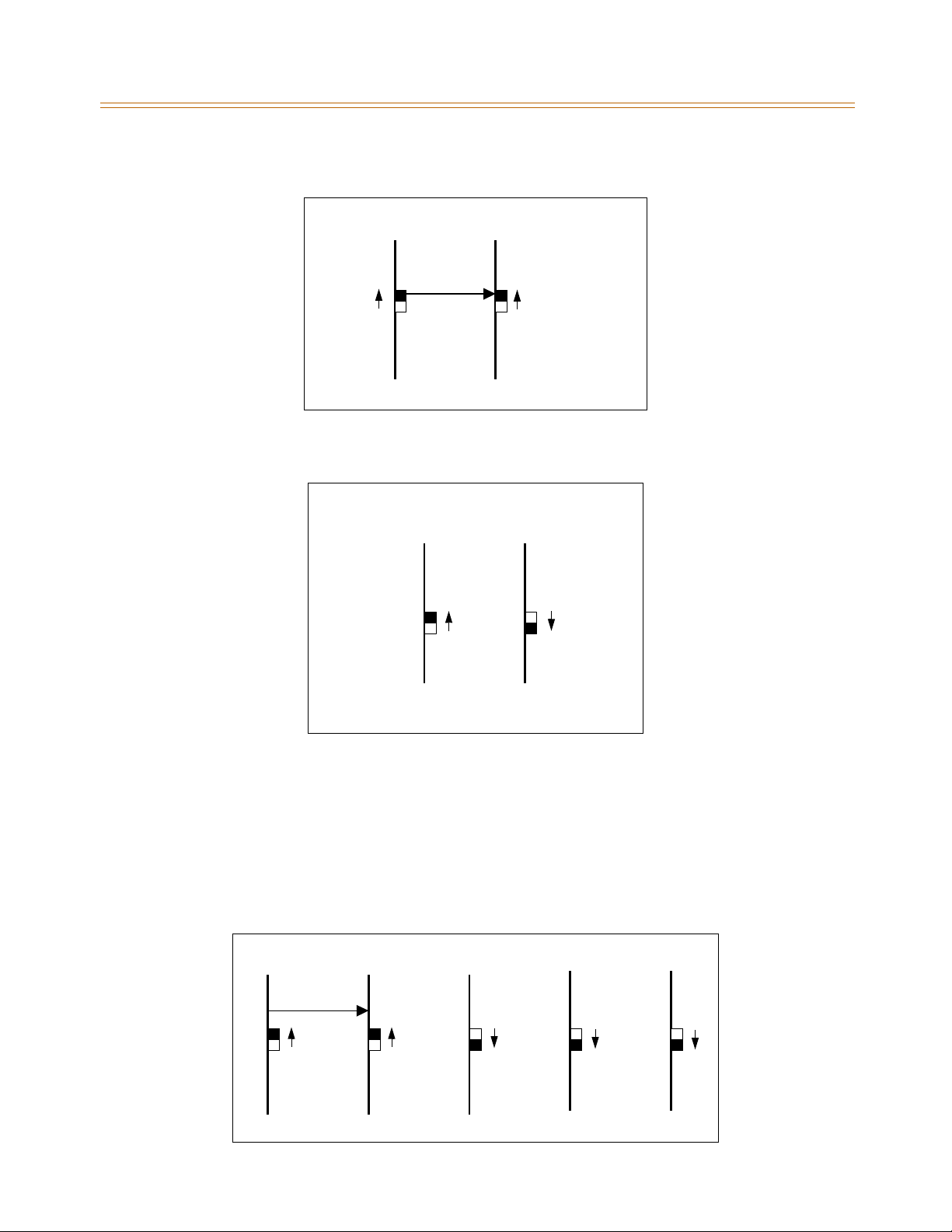
CO/PBX Connections 3-39
Chapter 3 - System Installation
(1) PRIB and (1) BRIB
PRIB BRIB
Sw2 On Switch 4, SW2 On
Install with the cable and set both PRIB and BRIB switches to the enable position (ON).
(1)T1IBand(1)BRIB
T1IB BRIB
SW3 On Switch 4, SW2 Off
If both cards in a phone switch are connected to a telephone company clock (not point-topoint T1), put the T1 clock switch in the enable position (ON) to allow it to receive clocking
from the telephone company directly. Do not install the clock cable.
Set the BRIB clock switch in the disable position (OFF), which allows the BRIB to synchronize
its timing off of the backplane (from the T1 clocking). If the T1 is a point-to-point T1, set the
BRIB to the enable position (ON), the T1 in the disable position (OFF), and do not install the
clock table.
(2) PRIBs and (3) T1IBs
PRIB1 PRIB2 T1IB1 T1IB2 T1IB3
SW2 On SW2 On SW3 Off SW3 Off SW3 Off
Page 74
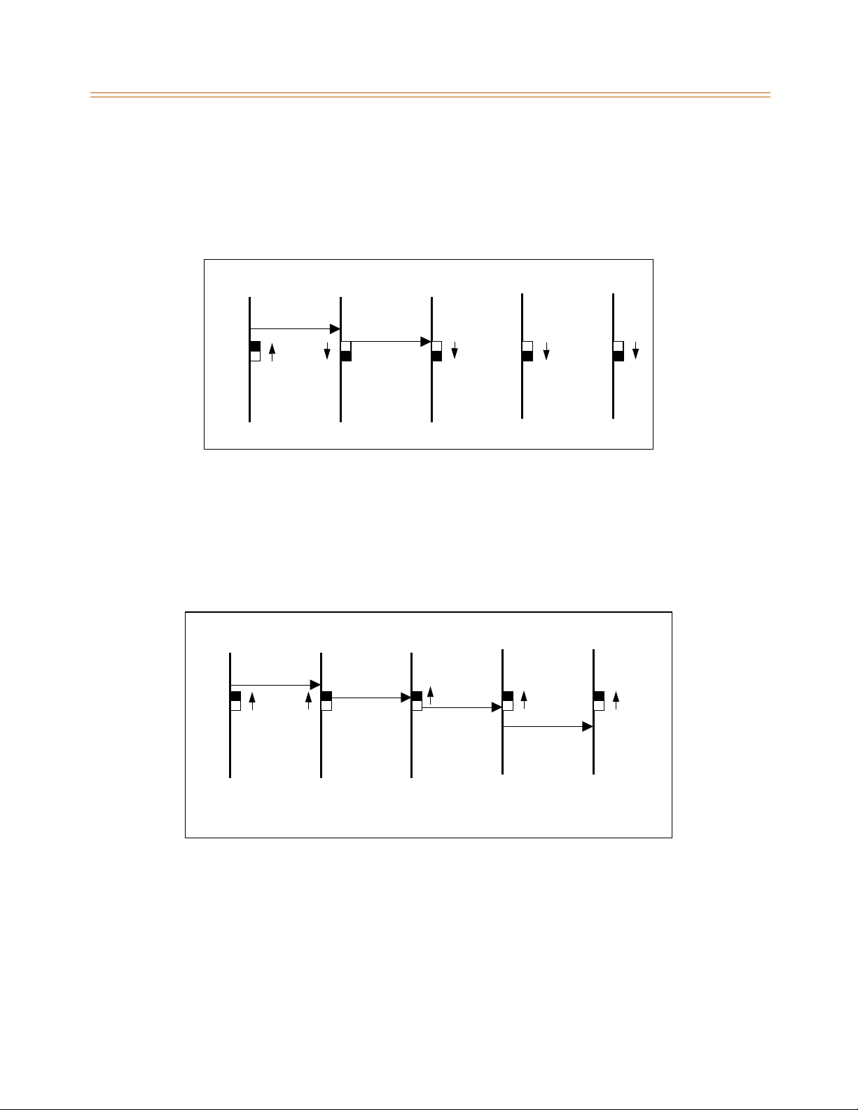
3-40 CO/PBX Connections
Chapter 3 - System Installation
The clock cable should be connected to the OUT position on the connector on the PRIB1. The
clock cable should be connected to the IN position on PRIB2. SW2 of the PRIB1 and PRIB2
should be placed in the ON position. The three T1IBs are not connected with the clock control
cable and SW3 on these boards should be in the OFF position.
(3) T1IBs and (2) PRIBs
T1IB1 T1IB2 T1IB3 PRIB1 PRIB2
SW3 On SW3 Off SW3 Off SW2 Off SW2 Off
The clock cable should be connected to the OUT position on the cable connector on the T1IB
and connected to the IN position on the connector on the T1IB2.
The clock cable should be connected to the OUT position on T1IB2 and connected to the IN
position on the T1IB3. SW3 of T1IB1 should be placed in the ON position, with SW3 on T1IB2
and T1IB3 being OFF. The two PRIBs are not connected with clock control cables, and SW2 on
the PRIBs should be in the OFF position.
(3) PRIBs and (2) BRIBs
PRIB1 PRIB2 PRIB3 BRIB1 BRIB2
SW2 On SW2 On SW2 On Switch 4, SW2 On Switch 4, SW2 On
The clock cable should be connected from the OUT position of the PRIB1 to the IN connectors
of all the cards and all clock switches should be in the ON position.
Page 75
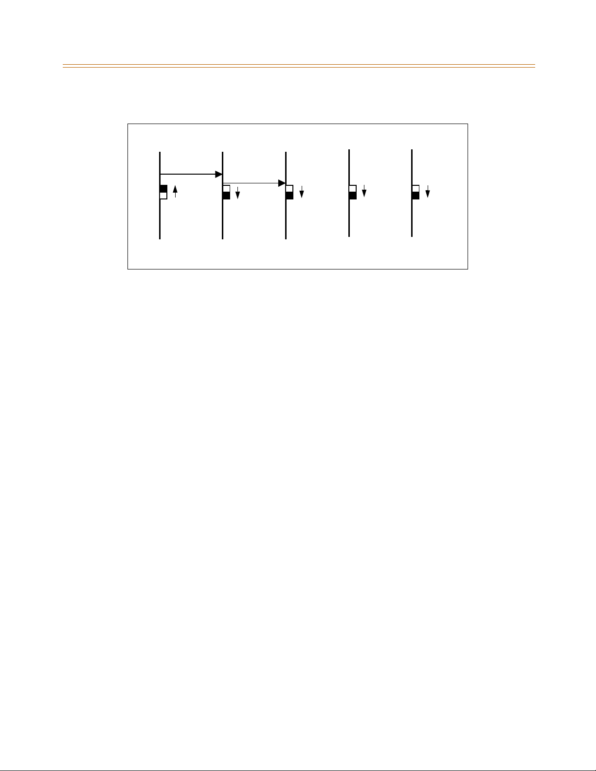
CO/PBX Connections 3-41
Chapter 3 - System Installation
(3) T1IBs and (2) BRIBs
T1IB1 T1IB2 T1IB3 BRIB1 BRIB2
SW3 On SW3 Off SW3 Off Switch 4, SW2 Off Switch 4, SW2 Off
The clock OUT cable from T1IB1 should be connected to the clock IN cable of the T1IB2 and
the clock OUT cable from T1IB2 should be connected to the clock IN cable of T1IB3. SW3 of
T1IB1 should be in the ON position, and SW3 of T1IB2 and T1IB3 should be in the OFF
position. The two BRIBs are not connected with clock control cables and SW2 of the BRIB
cards are placed in the OFF position.
Clock Chain Using T1 / PRIB / BRIB
The following four illustrations are clock chain examples that apply to PRIB or T1 use. Arrows
on the illustrations represent data flow. The BRIB clock chain is similar, in that you always
connect:
IN of LMU1 to OUT of the BRIB closest to the LMU1
OUT of a BRIB in Cabinet 1 to the IN of next closest BRIB
IN of LMU2 to OUT of the BRIB closest to the LMU2
IN from a BRIB in Cabinets 1 or 2 to the next closest BRIB
IN from the last BRIB to OUT of LMU2.
The callout of Figure 3-24: Case 1 of Clock Chain, that pertains to setting the Clock Source
Switch to either PRI/BRI or T1, is applicable to all examples.
TheexpandedviewcalloutatthetoprightofFigure 3-26: Case 3 of Clock Chain shows the
connectors on LMU2 when there is a T1 or ISDN card in the associated Cabinet. The expanded
view callout at the middle right of the same illustration shows the connection required for
Cabinets 1 or 2 when the Cabinet(s) do not have T1 or ISDN cards in use.
Page 76
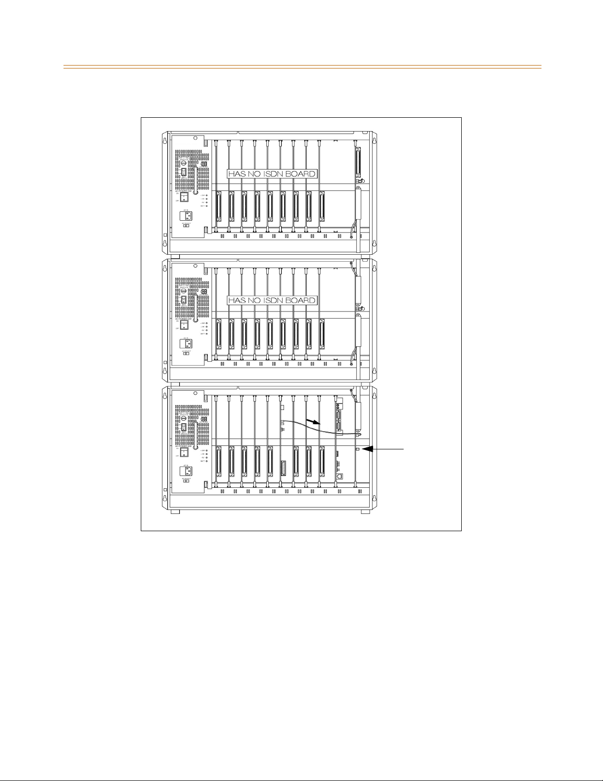
3-42 CO/PBX Connections
Chapter 3 - System Installation
Figure 3-24: Case 1 of Clock Chain
Set Clock
Source
Switch to
PRI/BRI
or to T1
Page 77
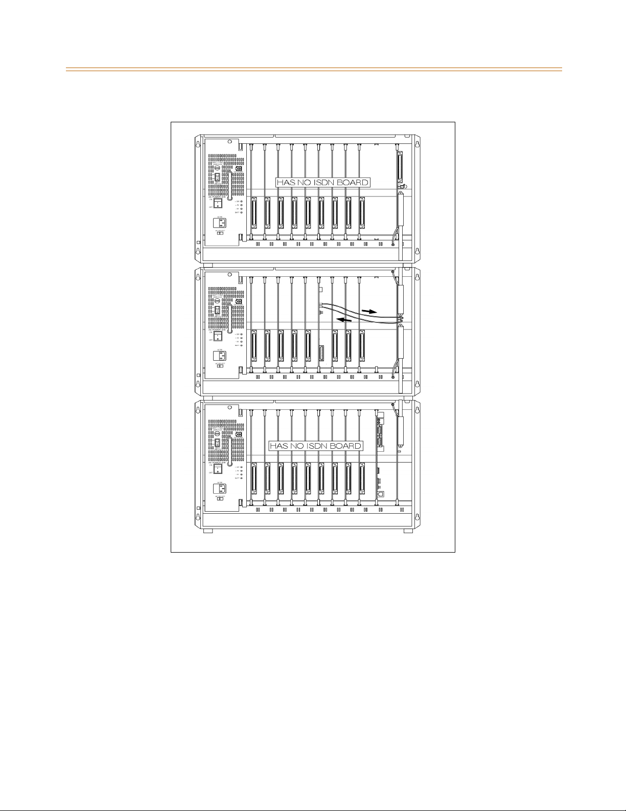
CO/PBX Connections 3-43
Chapter 3 - System Installation
Figure 3-25: Case 2 of Clock Chain
Page 78
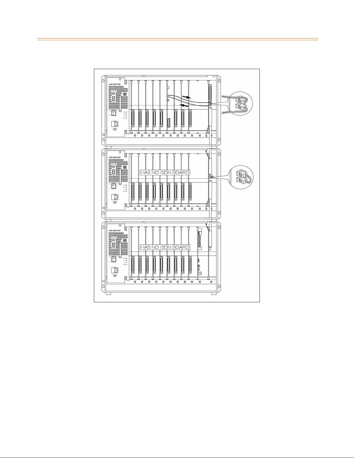
3-44 CO/PBX Connections
Chapter 3 - System Installation
IN OUT
OUT IN
IN OUT
OUT IN
Figure 3-26: Case 3 of Clock Chain
Page 79
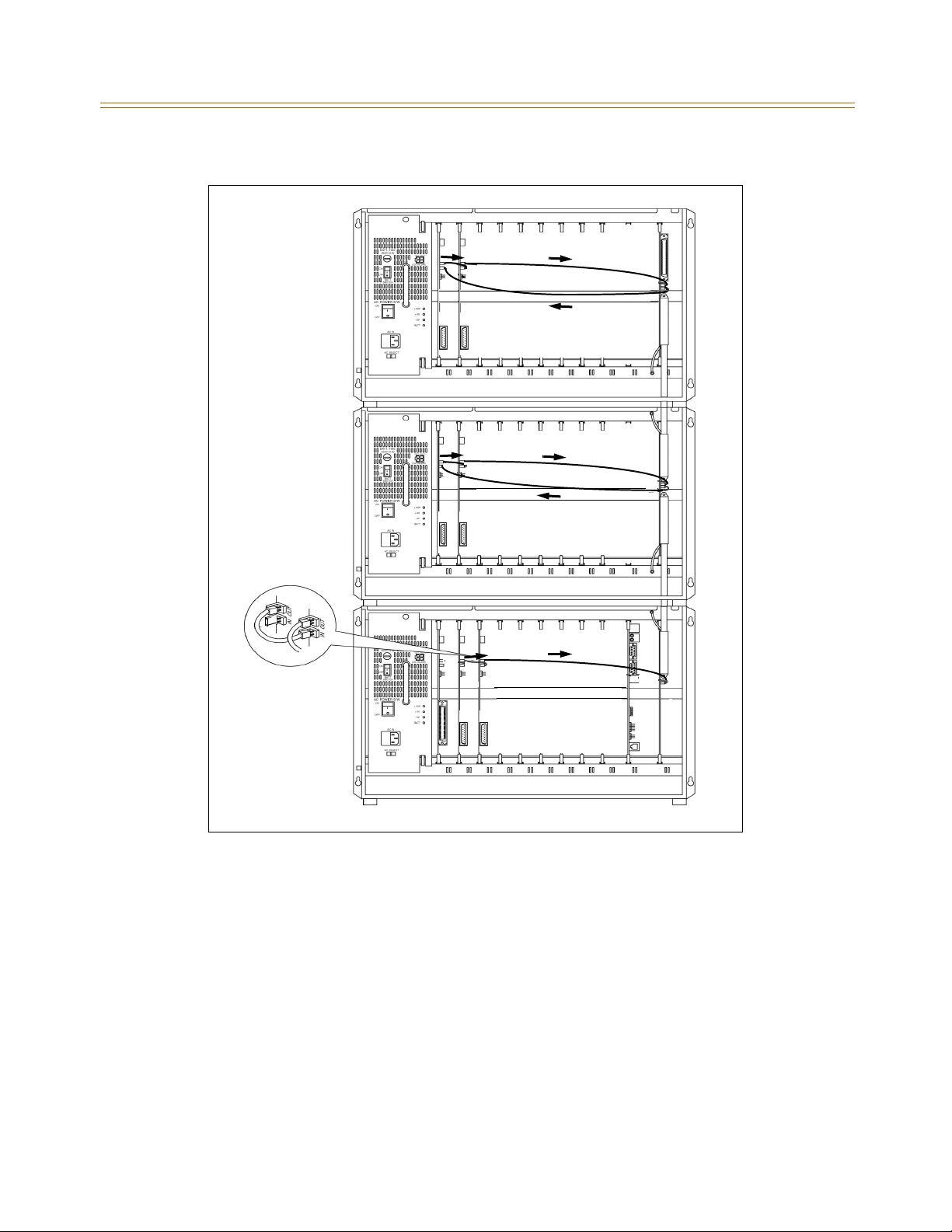
CO/PBX Connections 3-45
Chapter 3 - System Installation
Figure 3-27: Case 4 of Clock Chain
Page 80

3-46 Station Connections
Chapter 3 - System Installation
Station Connections
The system can be equipped with any combination of the six station boards; DTIB12, DTIB24,
ETIB, SLIB, SLIBE, and SLIBC. The station interface boards can be installed in any universal card
slot in the Cabinets. It is recommended that slots beginning from slot 0 be used for station
interface boards. Also, since the first port of the DTIB is the database access port (the only
port which enables admin programming by default), it is strongly recommended that a
DTIB12 or DTIB24 be installed in slot 0 and a Digital Keyset w/LCD be connected to the first
port.
Electronic Telephone Interface Board
The Electronic Telephone Interface Board (ETIB) board provides the interface to twelve
electronic telephones or DSS/BLF terminals. The card has one LED indicator for off-hook/in
usestatus.TheETIBcardextractorsarecolorcodedgreen.
There is one 50-pin female amphenol connectors labeled Conn2 located on the front of the
card. This allows the system to be cabled to the main distribution frame (MDF). 25-pair
telephone cabling must be prepared with mating connectors to extend the interface circuits
to the MDF. The cables should be routed through the cable clamps at the bottom of the KSU
to the MDF. These cables are then terminated on industry standard 66M1-50 type
punchdown connector blocks. It is recommended that 66M1-50 split blocks with bridging
clips be used to simplify troubleshooting and to quickly isolate faults.
The only telephone that can be used for database programming is the digital
Executive display telephone.
Page 81
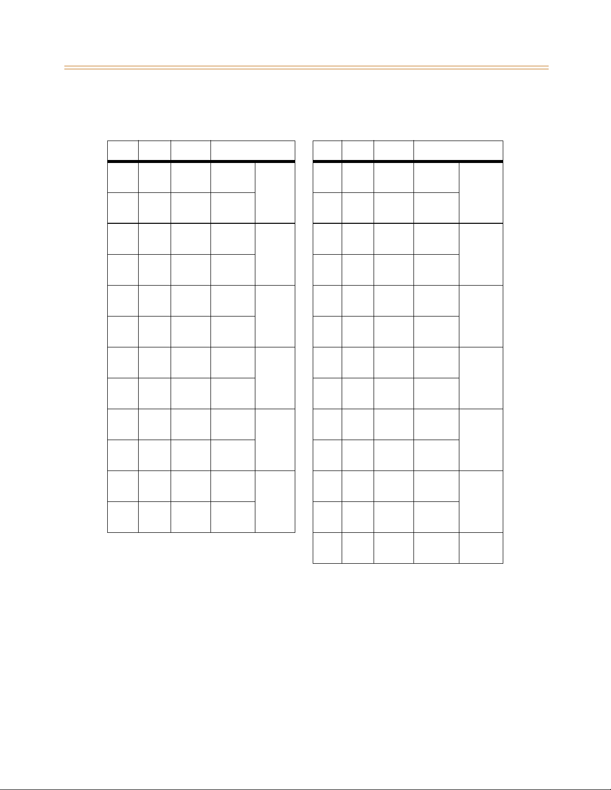
Station Connections 3-47
Chapter 3 - System Installation
Table 3-18: ETIB Wiring
Pair PIN # Color Description Pair PIN # Color Description
1261WH/BL
BL/WH
2272WH/OR
OR/WH
3283WH/GN
GN/WH
4294WH/BN
BN/WH
5305WH/SL
SL/WH
6316RD/BL
BL/RD
7327RD/OR
OR/RD
8338RD/GN
GN/RD
9349RD/BN
BN/RD
10 3510RD/SL
SL/RD
VT-1
VR-1
DT-1
DR-1
VT-2
VR-2
DT-2
DR-2
VT-3
VR-3
DT-3
DR-3
VT-4
VR-4
DT-4
DR-4
VT-5
VR-5
DT-5
DR-5
CKT1 13 3813BK/GN
GN/BK
14 3914BK/BN
BN/BK
CKT2 15 4015BK/SL
SL/BK
16 4116YL/BL
BL/YL
CKT3 17 4217YL/OR
OR/YL
18 4318YL/GN
GN/YL
CKT4 19 4419YL/BN
BN/YL
20 4520YL/SL
SL/YL
CKT5 21 4621VI/BL
BL/VI
22 4722VI/OR
OR/VI
VT-7
VR-7
DT-7
DR-7
VT-8
VR-8
DT-8
DR-8
VT-9
VR-9
DT-9
DR-9
VT-10
VR-10
DT-10
DR-10
VT-11
VR-11
DT-11
DR-11
CKT7
CKT8
CKT9
CKT10
CKT11
11 3611BK/BL
BL/BK
12 3712BK/OR
OR/BK
VT-6
VR-6
DT-6
DR-6
CKT6 23 4823VI/GN
GN/VI
24 4924VI/BN
BN/VI
25 5025VI/SL
SL/VI
VT-12
VR-12
DT-12
DR-12
CKT12
Page 82
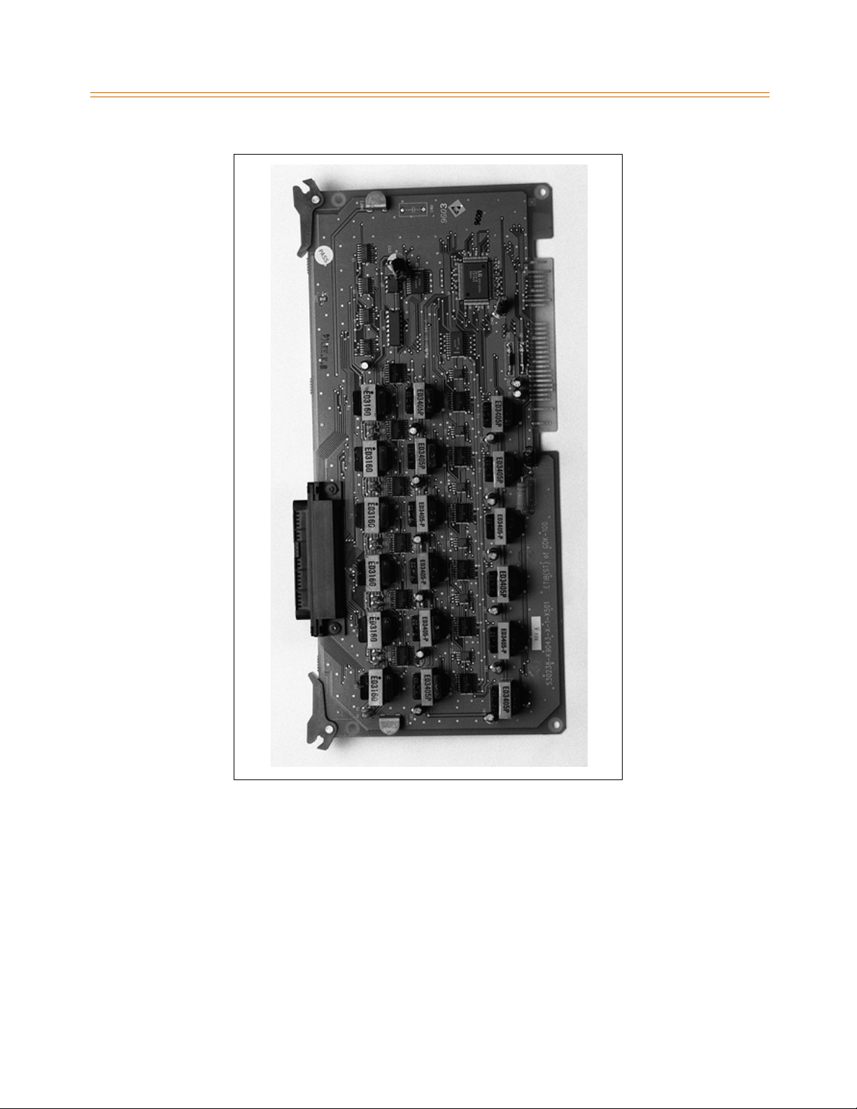
3-48 Station Connections
Chapter 3 - System Installation
Figure 3-28: Electronic Telephone Interface Board (ETIB)
Page 83
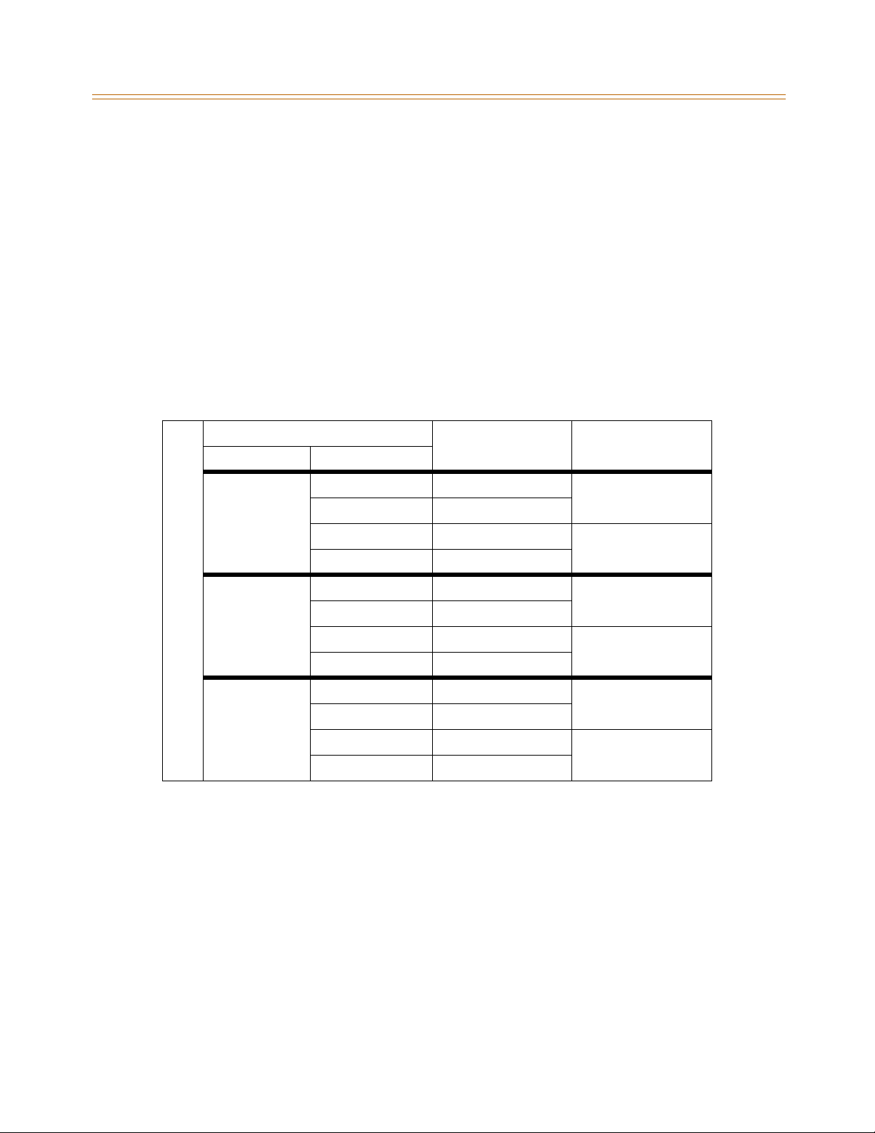
Station Connections 3-49
Chapter 3 - System Installation
Single Line Interface Board
The single line interface board (SLIB) provides the interface to six 2500-type telephones. The
SLIBE and SLIBC provide the interface to twelve 2500-type telephones. The SLIB signals
interface with industry-standard ringers and message waiting lights.
Three RJ11 connectors are mounted on the SLIB and an industry standard RJ21-type female
connector is mounted on the front edge of the PCB for connection to the station interfaces. In
addition, one LED is mounted on the PCB to indicate the in use state of the connected
telephones. It will turn on when one or more ports are busy.
TheSLIBcansupportaDTRUboard(2DTMFreceivers)andaMSGUboardinadaughter
board type arrangement. The SLIBE and SLIBC can support a DTRU4 board (4 DTMF receivers)
and two MSGU boards in a daughter board type arrangement.
Table 3-19: SLIB Wiring
SLIB Connector
Connector Pin # 3M Connection 6M Connection
I M3 3 Tip 6 Tip 6
S 2Ring6Ring6
S 4 Tip 5 Tip 5
U 1Ring5Ring5
E M2 3 Tip 4 Tip 4
5 2Ring4Ring4
4 Tip 3 Tip 3
R 1Ring3Ring3
E M1 3 Tip 2 Tip 2
V 2Ring2Ring2
A 4 Tip 1 Tip 1
1Ring1Ring1
Page 84
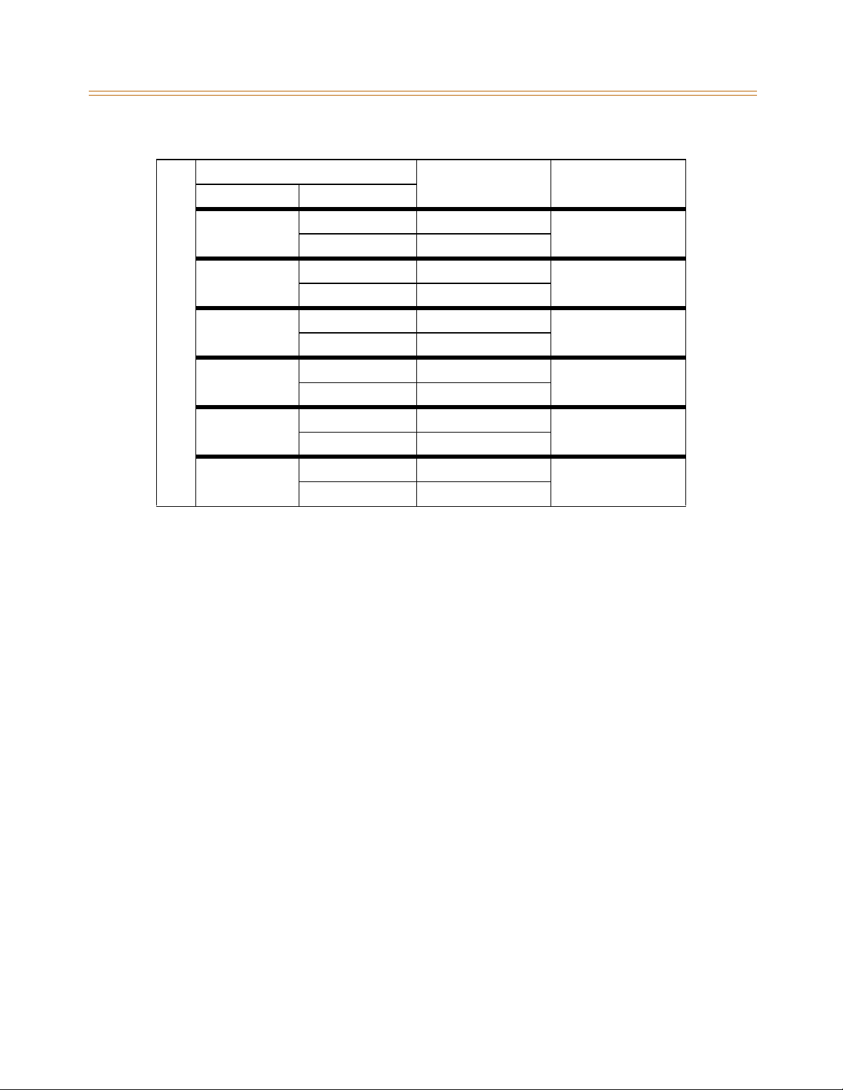
3-50 Station Connections
Chapter 3 - System Installation
SLIB Connector
Connector Pin # 3M Connection 6M Connection
M6 3 Tip 6 Tip 6
2Ring6Ring6
I M5 3 Tip 5 Tip 5
S 2Ring5Ring5
S M4 3 Tip 4 Tip 4
U 2Ring4Ring4
E M3 3 Tip 3 Tip 3
6 2Ring3Ring3
M2 3 Tip 2 Tip 2
2Ring2Ring2
M1 3 Tip 1 Tip 1
2Ring1Ring1
Page 85
Station Connections 3-51
Chapter 3 - System Installation
Table 3-20: SLIBE & SLIBC Wiring
Pair PIN # Color Description Pair PIN # Color Description
1261WH/BL
2272WH/OR
3283WH/GN
4294WH/BN
5305WH/SL
6316RD/BL
7327RD/OR
8338RD/GN
9349RD/BN
10 35
10
BL/WH
OR/WH
GN/WH
BN/WH
SL/WH
BL/RD
OR/RD
GN/RD
BN/RD
RD/SL
SL/RD
Ring 1
Tip 1
Ring 2
Tip 2
Ring 3
Tip 3
Ring 4
Tip 4
Ring 5
Tip 5
Ring 6
Tip 6
Ring 7
Tip 7
Ring 8
Tip 8
Ring 9
Tip 9
Ring 10
Tip 10
SLIBE & SLIBC Station Ports
13 38
13
14 39
14
15 40
15
16 41
16
17 42
17
18 43
18
19 44
19
20 45
20
21 46
21
22 47
22
BK/GN
GN/BK
BK/BN
BN/BK
BK/SL
SL/BK
YL/BL
BL/YL
YL/OR
OR/YL
YL/GN
GN/YL
YL/BN
BN/YL
YL/SL
SL/YL
VI/BL
BL/VI
VI/OR
OR/VI
11 36
11
12 37
12
BK/BL
BL/BK
BK/OR
OR/BK
Ring 11
Tip 11
Ring 12
Tip 12
23 48
23
24 49
24
25 50
25
VI/GN
GN/VI
VI/BN
BN/VI
VI/SL
SL/VI
InstallingtheDTRUorDTRU4Module
DTRU to SLIB
1. Unpack the DTRU module from its antistatic conductive bag.
2. Locate the CON1 and CON2 connectors on the DTRU module.
3. Locate the CN1 and CN2 connectors on the SLIB.
4. Position the DTRU module so that its CON2 aligns with the CN1 connector and its CON1
aligns with the CN2 connector on the SLIB.
5. Push the DTRU module onto these connectors to seat it securely.
Page 86

3-52 Station Connections
Chapter 3 - System Installation
DTRU4 to SLIBE or SLIBC
1. Unpack the DTRU module from its antistatic conductive bag.
2. Locate the CN1 and CN2 connectors on the DTRU4 module.
3. Locate the CN1 and CN2 connectors on the SLIB.
4. Position the DTRU4 module so that its CON1 aligns with the CN1 connector and its CON2
aligns with the CN2 connector on the SLIBE or SLIBC.
5. Push the DTRU4 module onto these connectors to seat it securely.
Installing the MSGU or MSGU48 Board
The Message Wait Lamp Relay Control (MSGU) provides Message Wait Lamp Relay Control for
message lamp single line telephones. The MSGU board mounts on the SLIB board as a
daughter board type arrangement.
MSGU to SLIB
1. Unpack the MSGU module from its antistatic conductive bag.
2. Locate the CONN1 and CONN2 connectors on the MSGU module.
3. Locate the CN3 and CN4 connectors on the SLIB.
4. Position the MSGU module so that its CONN1 aligns with CN4 and its CONN2 aligns with
the CN3 connector on the SLIB.
5. Push the MSGU module onto these connectors to seat it securely.
MSGU48 to SLIBE or SLIBC
1. Unpack the MSGU48 module from its antistatic conductive bag.
2. Locate the CONN1 and CONN2 connectors on the MSGU48 module.
3. Locate the CN6 and CN7 and the CN5 and CN8 connectors on the SLIBE or SLIBC. Either
pair can be used to mount an MSGU48. Use the second pair to mount a second MSGU48.
4. Position the MSGU48 module so that either its:
CONN1 aligns with CN6 and its CONN2 aligns with the CN7 connector on the SLIBE or
SLIBC.
-or-
CONN1 aligns with CN5 and its CONN2 aligns with the CN8 connector on the SLIBE or
SLIBC.
5. Push the MSGU48 module onto these connectors to seat it securely.
Adjusting Modem Settings
When using modems connected to SLT ports on the XTS, the gain settings on the SLT port
when using T1 as access to the CO should be set to 0 dB (maximizes modem speed).
CO to SLT Call via a T1 TIE Trunk:
1. Access the specific trunk type above.
2. Hookflash, dial 638 8 on the keypad, then hookflash again.
3. Hang up.
Page 87

Station Connections 3-53
Chapter 3 - System Installation
CO to SLT Call via a T1 Trunk:
1. Access the specific trunk type above.
2. Hookflash, dial 638 6 on the keypad, then hookflash again.
3. Hang up.
SLT to SLT Call:
1. Place an intercom call from 1 SLT to another.
2. Hookflash, dial 638 5 on the keypad, then hookflash again.
3. Hang up.
No adjustment is needed if access to the CO is accomplished by standard loop/ground start
trunk circuits. These trunk types are set to 0 dB by default.
In all cases the maximum modem speed is not as much as if the modem were connected
directly to the CO line.
Testing proves that a baud rate of 33600 can be achieved with SLT-T1 lines. Typical
connection speeds with SLT-T1 are 22700-33600. Typical connection speeds with SLT-Loop/
Ground Start are 17400-23800.
All results were obtained using a 56K U.S. Robotics Sportster modem.
Page 88
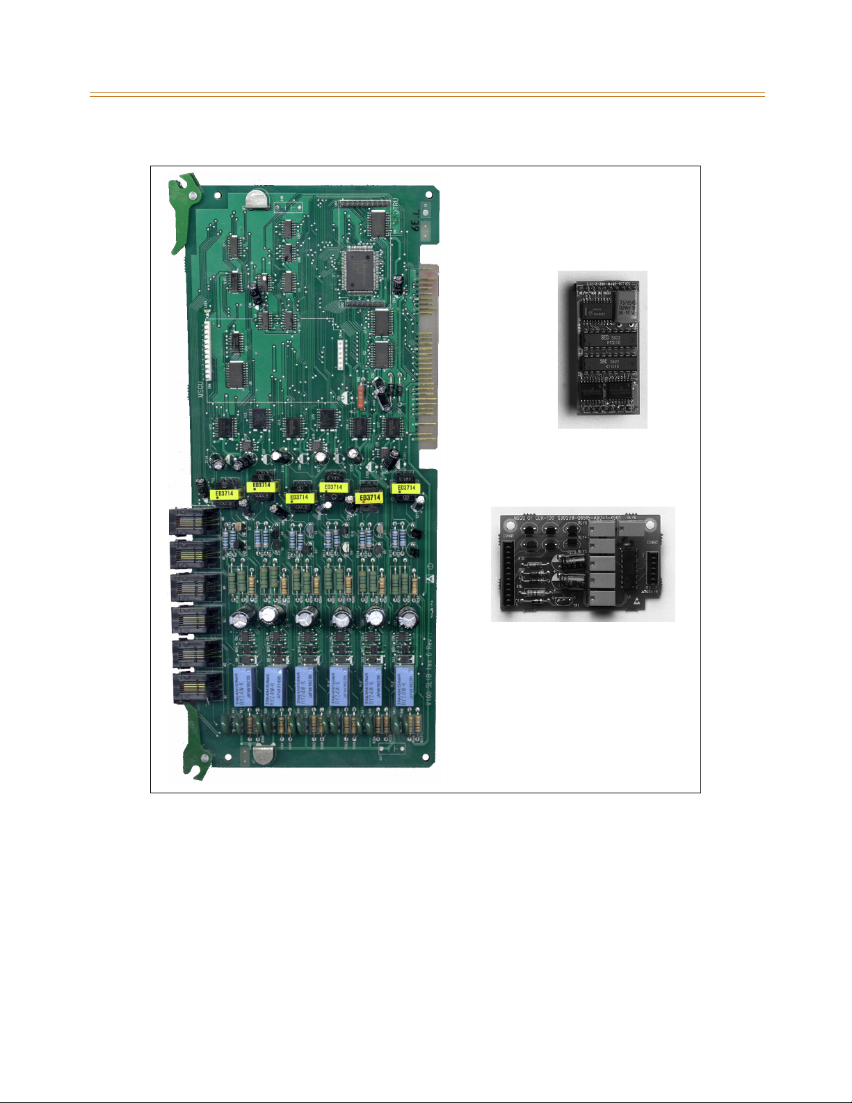
3-54 Station Connections
Chapter 3 - System Installation
CN1
CON2
CN2
DTRU
CN4
CN3
CON1
MSGU
CONN1
Figure 3-29: SLIB w/MSGU and DTRU Module Installation
CONN2
Page 89
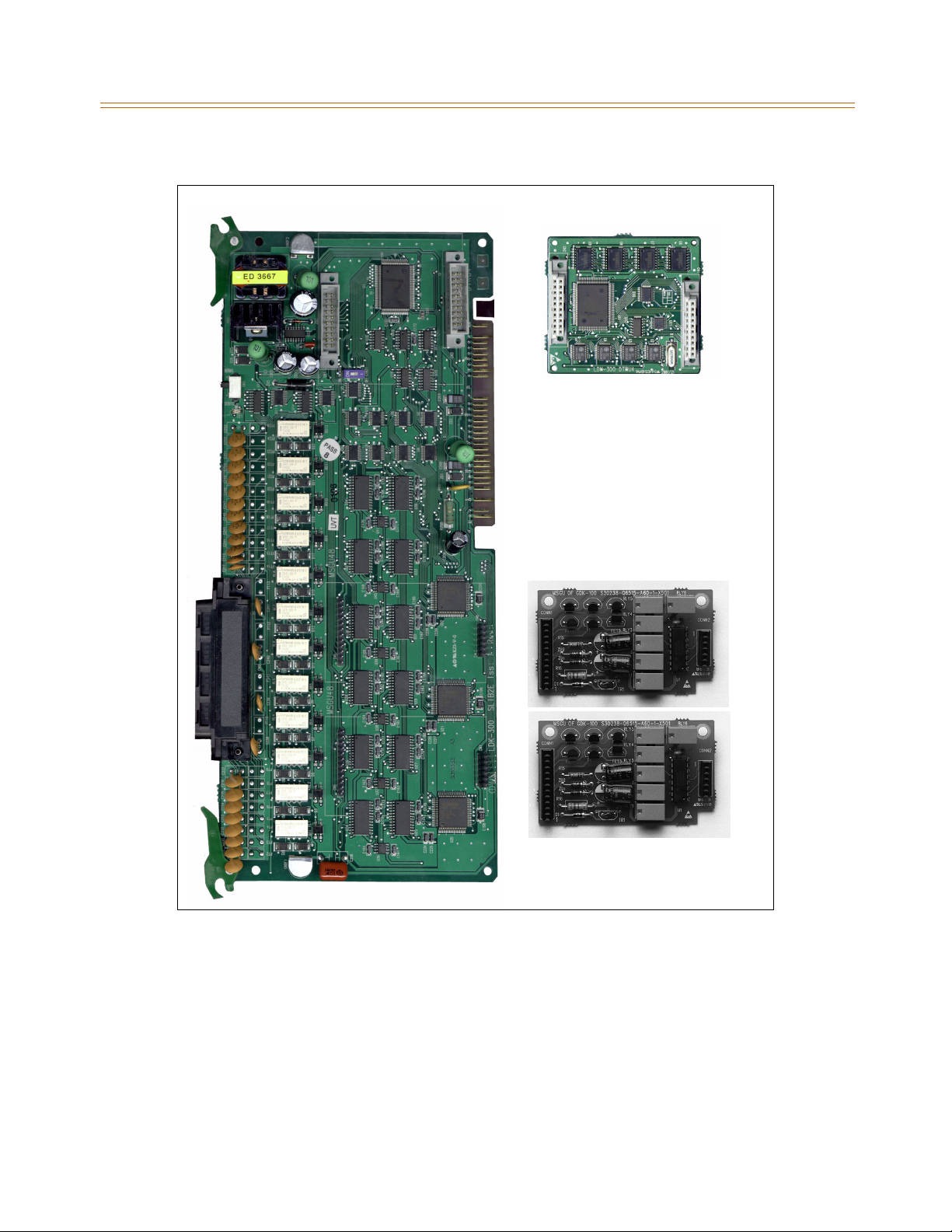
Station Connections 3-55
Chapter 3 - System Installation
U4
R
T
D
CN1
CN1
CN2
CN2
8
)
2
U4
1
-
G
S
s7
t
M
CN5
CN6
CN8
CONN1
CN7
CONN1
r
o
p
r
o
f
(
8
)
4
6
-
SGU
s1
t
r
M
o
p
r
o
f
(
Figure 3-30: SLIBE & SLIBC w/MSGU and DTRU4 Module Installation
CONN2
CONN2
Page 90

3-56 Station Connections
Chapter 3 - System Installation
Digital Telephone Interface Board
The Digital Telephone Interface Board (DTIB) provides digital voice and data communications
to/from digital telephones.
An industry standard RJ21 type female connector is mounted on the front edge of the PCB for
connection to the station interfaces.
The DTIB12 and DTIB24 boards provide the interface to 12 and 24 digital telephones
respectively. The card has one LED to indicate off-hook/in use status. The DTIB card extractors
are color coded green.
Cables
There is one 50-pin female amphenol connector labeled CN2 located on the front of the card.
This allows the system to be cabled to the main distribution frame (MDF).
25-pair telephone cabling must be prepared with mating connectors to extend the
interface circuits to the MDF.
Cables should be routed through the cable clamps at the bottom of the KSU to the MDF.
These cables are then terminated on industry standard 66M1-50 type punchdown
connector blocks.
It is recommended that 66M1-50 split blocks with bridging clips be used to simplify
troubleshooting and to quickly isolate faults.
LED1 shows status of the board (ON = in use, OFF = Idle).
Page 91
Station Connections 3-57
Chapter 3 - System Installation
Table 3-21: DTIB Wiring
Pair PIN # Color Description Pair PIN # Color Description
1261WH/BL
BL/WH
2272WH/OR
OR/WH
3283WH/GN
GN/WH
4294WH/BN
BN/WH
5305WH/SL
SL/WH
6316RD/BL
BL/RD
7327RD/OR
OR/RD
8338RD/GN
GN/RD
9349RD/BN
BN/RD
10 35
10
RD/SL
SL/RD
DATA-R 1
DATA-T 1
DATA-R 2
DATA-T 2
DATA-R 3
DATA-T 3
DATA-R 4
DATA-T 4
DATA-R 5
DATA-T 5
DATA-R 6
DATA-T 6
DATA-R 7
DATA-T 7
DATA-R 8
DATA-T 8
DATA-R 9
DATA-T 9
DATA-R 10
DATA-T 10
DTIB12 Station Ports
13 38
13
14 39
14
15 40
15
16 41
16
17 42
17
18 43
18
19 44
19
20 45
20
21 46
21
22 47
22
BK/GN
GN/BK
BK/BN
BN/BK
BK/SL
SL/BK
YL/BL
BL/YL
YL/OR
OR/YL
YL/GN
GN/YL
YL/BN
BN/YL
YL/SL
SL/YL
VI/BL
BL/VI
VI/OR
OR/VI
DATA-R 13
DATA-T 13
DATA-R 14
DATA-T 14
DATA-R 15
DATA-T 15
DATA-R 16
DATA-T 16
DATA-R 17
DATA-T 17
DATA-R 18
DATA-T 18
DATA-R 19
DATA-T 19
DATA-R 20
DATA-T 20
DATA-R 21
DATA-T 21
DATA-R 22
DATA-T 22
DTIB24 Station Ports
11 36
11
12 37
12
BK/BL
BL/BK
BK/OR
OR/BK
DATA-R 11
DATA-T 11
DATA-R 12
DATA-T 12
23 48
23
24 49
24
25 50
25
VI/GN
GN/VI
VI/BN
BN/VI
VI/SL
SL/VI
DATA-R 23
DATA-T 23
DATA-R 24
DATA-T 24
Page 92
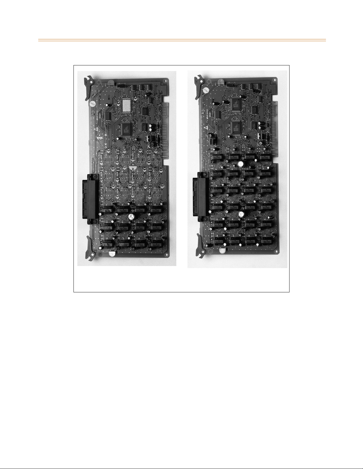
3-58 Station Connections
Chapter 3 - System Installation
DTIB12 DTIB24
Figure 3-31: Digital Telephone Interface Board (DTIB)
Page 93
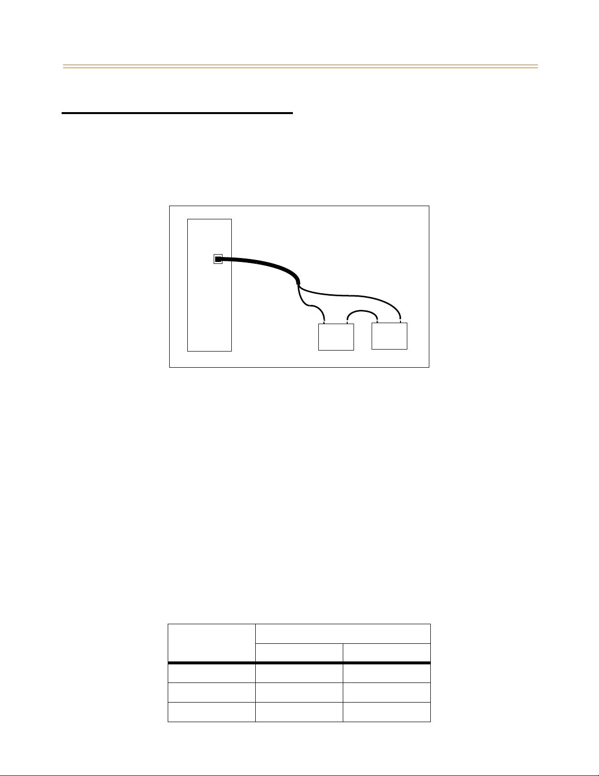
System Wiring 3-59
Chapter 3 - System Installation
System Wiring
Battery Backup Wiring Installation
The system can be equipped to operate from external batteries if local AC power fails. The
backup batteries are connected to the strip connector on the front of the PSU as shown:
PSU
24VDC
Blue
Red
+
Battery Battery
12VDC
Figure 3-32: Battery Back-Up Wiring
+
--
12VDC
The external batteries must provide 24 Volts DC. This is generally accomplished by
connecting two 12-volt batteries per Cabinet in a series arrangement. Operation on batteries
is controlled by the PSU. The PSU provides charging current to the batteries during normal
AC power operation at a maximum of about 1 amp. After connecting the batteries for
backup, ensure that you turn the BATT.SWITCH (located on the faceplate of the PSU) to the
ON position so that when AC power fails the batteries will automatically provide power.
During battery operation, the PSU discontinues battery operation if the AC power is
reapplied or the battery voltage is too low to maintain proper system operation. If a lowbattery cut-off occurs and a new battery must be installed, turn the BATT. SWITCH to the OFF
position, replace the battery, then turn the BATT.SWITCH to the ON position.
The length of time the system operates on the batteries is dependent on several elements
including: battery charge state, condition of the batteries, capacity of the batteries, and the
size of the system (number of station ports).
The following chart gives the approximate backup time for several system sizes and different
battery capacities in ampere-hours.
Table 3-22: System BackUp Duration
Battery Capacity
Ports
32 5.5 Hours 11.0 Hours
64 3.5 Hours 7.0 Hours
96 2.25 Hours 4.5 Hours
20AH 40AH
Page 94
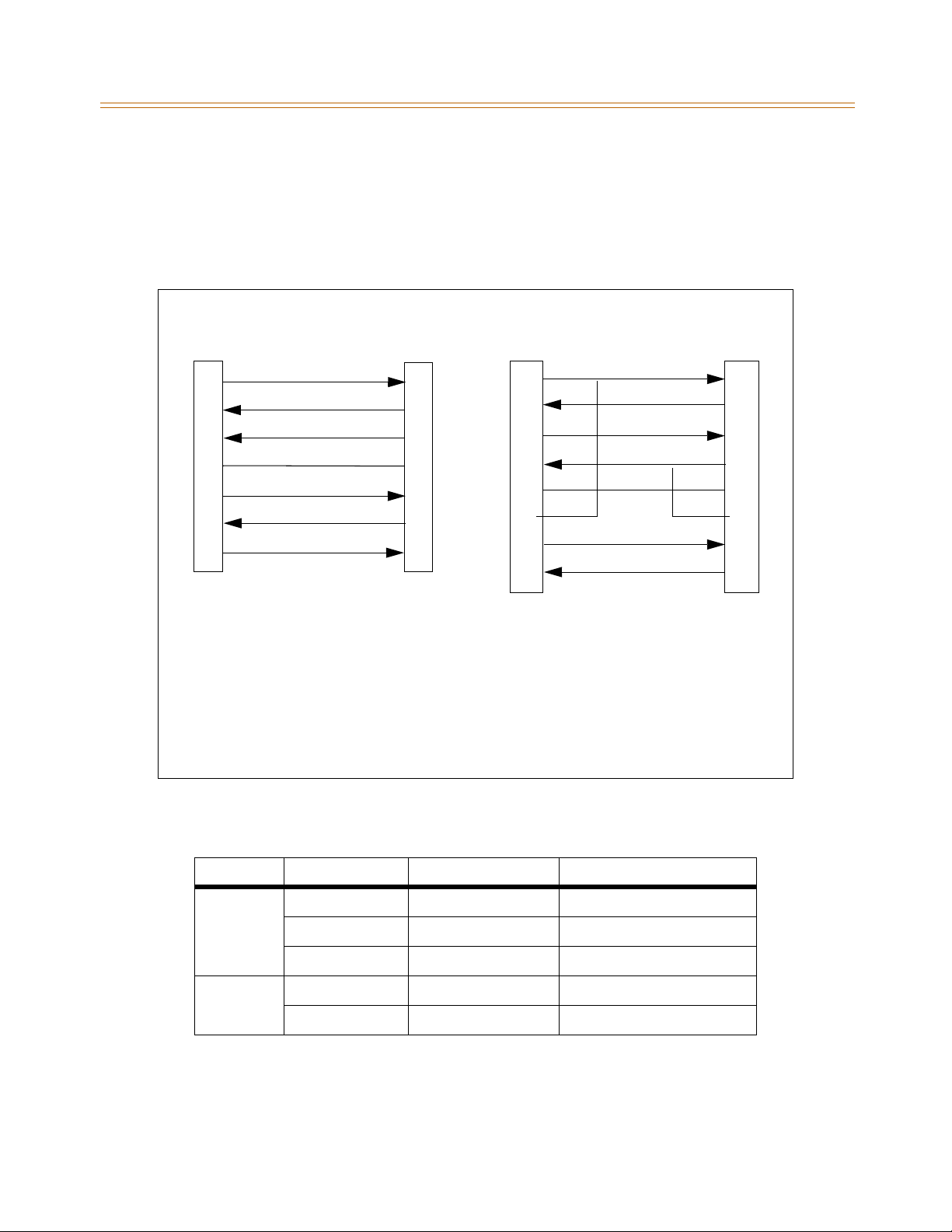
3-60 System Wiring
Chapter 3 - System Installation
RS-232C Wiring on MPB and SIU
The MPB1 contains one and the MPB2 contains two standard RS-232C interfaces (SMC1 is
port 1 on MPB1 and MPB2; UART is port 5 on MPB2 only). The SIU on the MISB contains two
standard RS-232C interfaces (port 3 and port 4). The RS-232C is connected by a 9-pin
connector.
Standard Straight Through Cable
9PIN 9PIN
TD
2
RD
3
DSR
4
SG
5
DTR
6
CTS
7
RTS
8
DB-9 connector for
RS-232C of CN3 on
MPB and SIU on MISB
RD
TD
DTR
SG
DSR
RTS
CTS
DB-9 connector
for RS-232C on
Terminal
2
3
4
5
6
7
8
Standard Null Modem Cable
9PIN 9PIN
DCD
RD
TD
DTR
SG
DSR
RTS
CTS
●
●
DB-9 connector
for RS-232C on
Terminal
1
2
3
4
5
6
7
8
DB-9 connector for
RS-232C of CN3 on
MPB and SIU on MISB
Note: Both cables are commercially available, prewired in the above configurations
LEGEND:
TD = Transmitted Data DCD = Data Carrier Detect
RD = Received Data DTR = Data Terminal Ready
RTS = Request To Send DSR = Data Set Ready
CTS = Clear To Send SG = Signal Ground
DTR
RD
DCD
DSR
CTS
RTS
TD
SG
4
3
2
1
5
6
8
7
Figure 3-33: RS-232 9-Pin Connector Cable Wiring
Table 3-23: MPB & SIU Communication Ports
Location Port Number Port Description Where it is connected
1SMCI MPB
MPB 2 Modem MPB
5 UART MPB2 only
3 RS-232 MISB
SIU
4 RS-232 MISB
Page 95
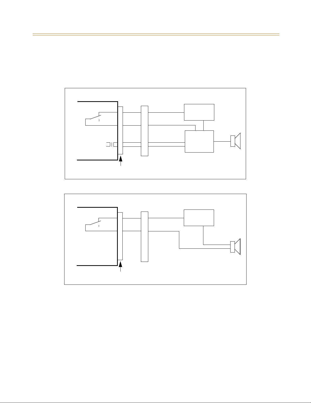
System Wiring 3-61
Chapter 3 - System Installation
MISB Wiring
The MISB has connections for 2 music sources, 2 external page zones and 4 relay contact
controls. The MISB connections are made by the 25-pair connector. The wiring connections
for the 25-pair cable are identified in Table 3-4 on page 3-20.
MISB
External paging
output
MISB
BL/WH
WH/BL
MDF
GN/BK
BK/GN
RJ21-type Connector
Figure 3-34: External Paging Wiring
OR/WH
WH/OR
MDF
External DC
Power Supply
External
Amplifier
External DC
Power Supply
RJ21-type Connector
Figure 3-35: Loud Bell Wiring
Page 96
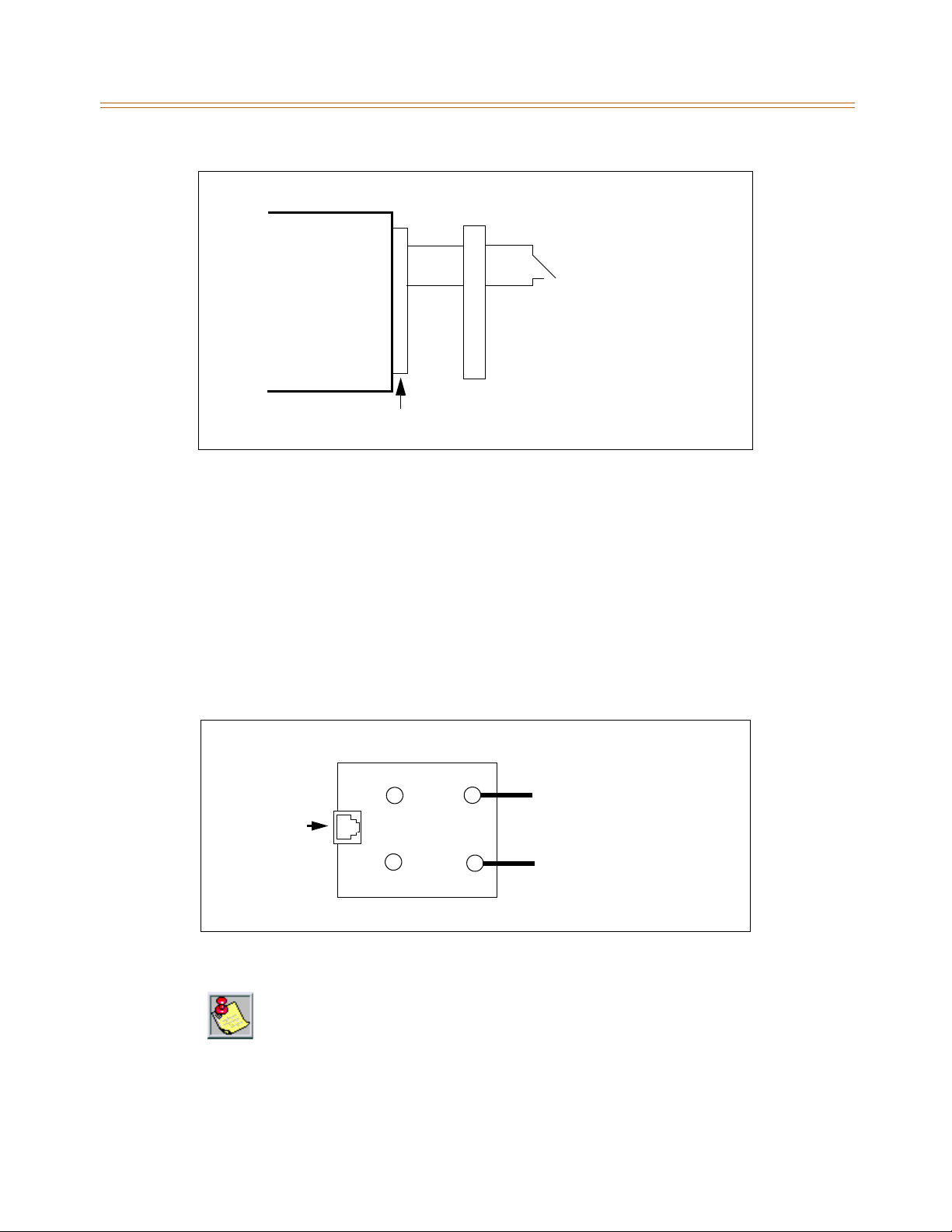
3-62 System Wiring
Chapter 3 - System Installation
Station Wiring
Station interface boards (DTIB24, ETIB, SLIB12) includes a 25-pair connector for station wiring
to the ports on the board. The following provides details on the interconnection of each type
of station interface board and the station jack.
Digital Keyset and Terminal Wiring
Wiring from the DTIB to station jack requires one-pair wire. Digitized voice, signaling, and
power are sent over this pair.
MISB
Figure 3-36: External Switch / Alarm Wiring
GN/YL
YL/GN
MDF
RJ21-type Connector
External
Switch
Figure 3-37 gives details on connections of station jacks to the system and Tab l e 3 -2 1 gives
the configuration of the 25-pair station connector arrangement and punchdown type block.
BK
R
RJ11
Y
G
Figure 3-37: Digital Station Jack Wiring
Only the firstpair (Red, Green onjack) should be connected backto the KSU.No other
pairs should be connected back to the KSU.
DIGITAL RING (RED)
DIGITAL TIP (GREEN)
Page 97
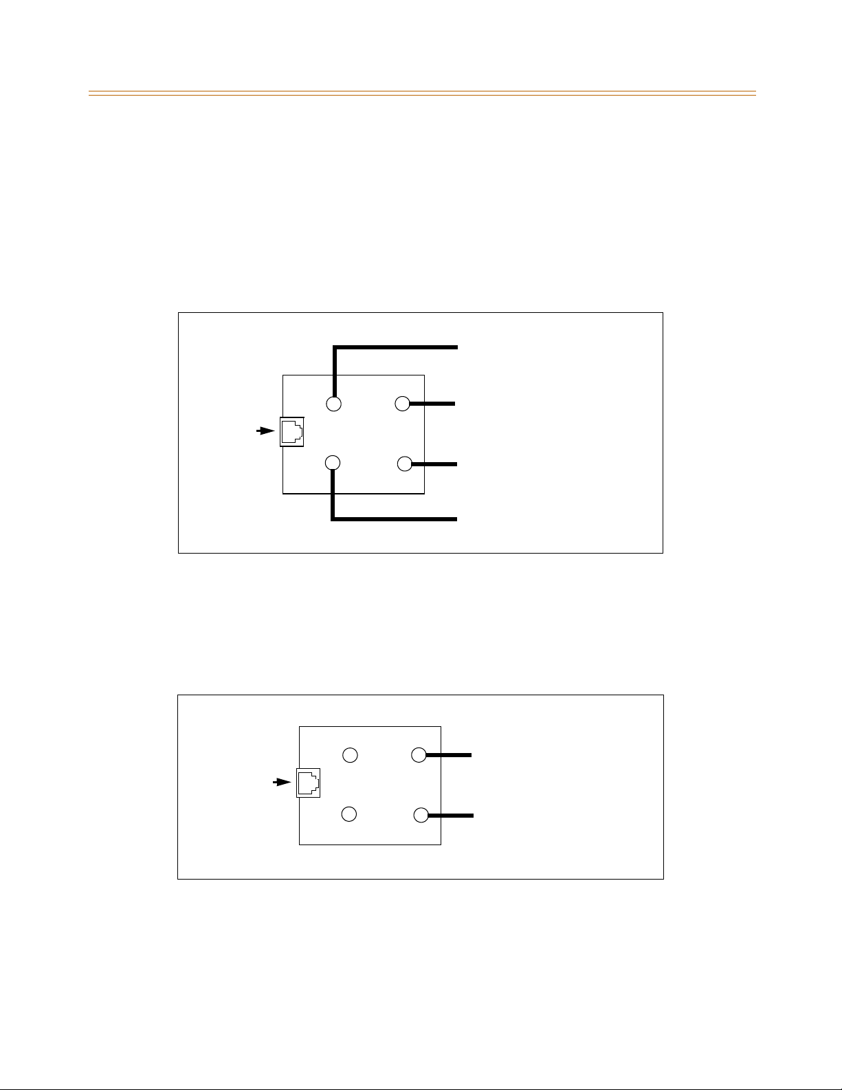
System Wiring 3-63
Chapter 3 - System Installation
Electronic Keyset and Terminal Wiring
Wiring from the ETIB to station jack requires two pairs of wire. The first pair provides the
audio or voice path, the second is for signaling or data path. The DATA pair is polarity
sensitive. Reversal does not harm the keyset or system, but the port does not function
properly when reversed. Power is delivered by applying DC voltage to the center tap of the
coupling transformers of each of the 2 pairs.
Figure 3-28 gives details on connections of station jacks to the system and Tab l e 3 -1 8 gives
the configuration of the 25-pair station connector arrangement and punchdown type block.
DATA TIP (BLACK)
VOICE RING (RED)
VOICE TIP (GREEN)
DATA RING (YELLOW)
RJ11
BK
R
Y
G
Figure 3-38: Electronic Station Wiring
Single Line Telephone Wiring
TheSLIBiswiredtoSLTdeviceswithasinglepairofwirewhichprovidesbatteryfeed,voice
and signaling to and from the SLT. Typical wiring to the SLT jack is shown in Figure 3-39 and
Ta bl e 3 -1 9 gives the configuration of the station connector arrangement when connected to
a punchdown-type block.
VOICE RING (RED)
RJ11
BK
R
Y
G
Figure 3-39: Single Line Telephone Wiring
VOICE TIP (GREEN)
Page 98
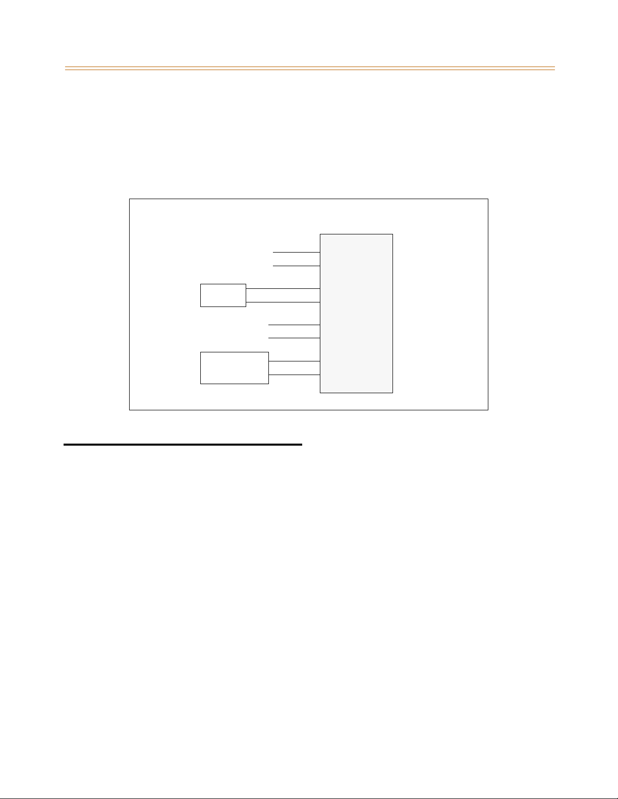
3-64 Wall Mounting the Electronic Key Telephone
Chapter 3 - System Installation
Power Failure Transfer Unit Wiring
The Power Failure Transfer Unit (PFTU) is wired from the 25-pair connector to the MDF, cross
connected to the CO Line inputs from the telephone company, to the CO Line inputs of the
system, and to Power Failure SLTs. The basic connections are shown in Figure 3-40 and the
connector configuration is given in Ta bl e 3 -1 9 . Note that the SLT may also be connected to a
SLIBasshowninthefigure.
MDF (PFTU)
CO L1
CO L2
LCOB E
SLT
SLIBE
Subscriber
BL/WH
WH/BL
OR/WH
WH/OR
GN/WH
WH/GN
BN/WH
WH/BN
Figure 3-40: PFTU Wiring
COR1-IN
COT1-IN
COR1-OUT
COT1-OUT
TEL1-R
TEL1-T
SLIB1-R
SLIB1-T
Wall Mounting the Electronic Key Telephone
All connections to the Electronic Key Telephone are fully modular. To wall mount the
Electronic Key Telephone, it is necessary to have one Wall Mount Kit and one standard-type
jack assembly designed for normal wall hanging applications.
1. Unplug the line cord from the phone. This line cord is not be required and should be
retained as a maintenance replacement item.
2. Lift the plastic number retainer upward and expose the screw underneath. Remove the
screw and the handset tab. Replace it with the handset tab from the Wall Mount Kit.
3. Be careful to position the tab so that the protrusion faces the hookswitch. This allows the
handset to remain secure when the telephone is on the wall. Replace the screw and snap
the number retainer into place.
4. Substitute the short modular cord from the Wall Mount Assembly into the modular
connector vacated by the line cord.
5. Align the wall mount baseplate with holes on the bottom of the telephone. Snap in place.
6. Now match the two key hole slots on the baseplate with the lugs on the 630-A type jack.
Align the modular connector and slide telephone into place. Refer to Figure 3-41 .
Page 99
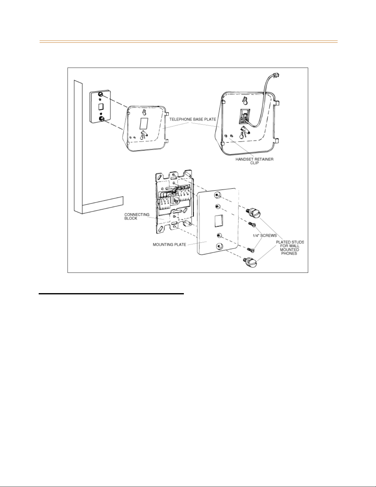
Wall Mounting the Digital Key Telephone 3-65
Chapter 3 - System Installation
Figure 3-41: Electronic Key Telephone Wall Mounting
Wall Mounting the Digital Key Telephone
To wall mount the Digital Key Telephone, it is necessary to use the Wall Mount bracket and
one standard-type jack assembly designed for normal wall hanging applications. Refer to
Figure 3-41 and Figure 3-42 .
1. Remove the handset from the cradle and locate the plastic retainer in the bottom of the
hook-switch well area. Push the plastic retainer slowly upward until it is free. Locate the
tab on the plastic retainer and make sure the tab is toward you, then place it back into its
holder. Slide the plastic retainer all the way down into its channel. Part of the retainer
remains above its holder to hold the handset secure for the wall mount configuration.
2. Turn the telephone over and unplug the line cord. If the line cord is not plugged into the
wall jack assembly, re-route the line cord through the access channel on the top of the
telephone. If the line cord is plugged into the wall jack assembly, run the line cord
through the hole provided and plug into the connector on the back of the telephone.
3. Line up the hooks on the top and bottom of the wall mount bracket so they can engage
with the slots cut into the bottom of the telephone base. Insert the bottom hooks first.
Slide the mounting bracket slowly downwards until the top tabs slide into the top slots
and snap in place.
Page 100
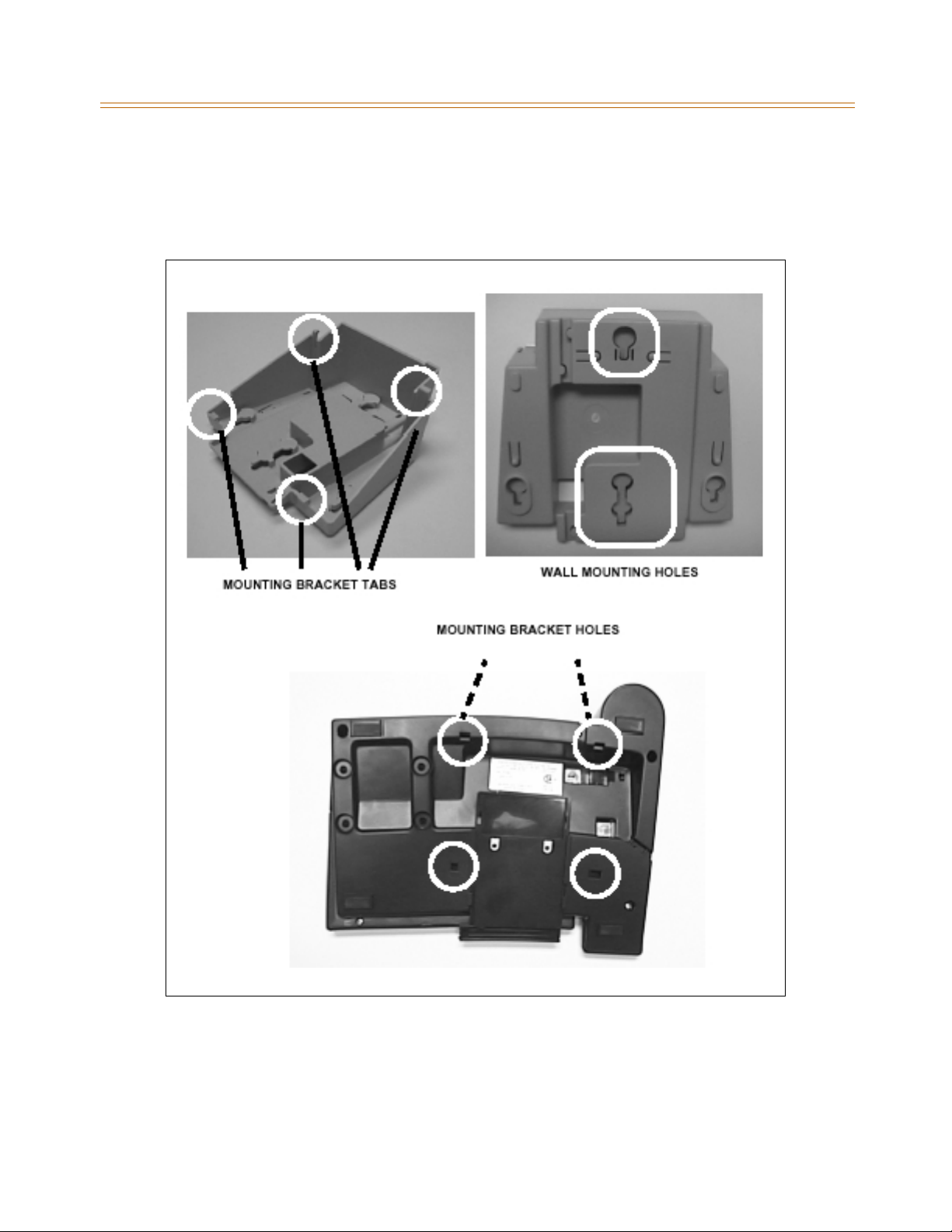
3-66 Wall Mounting the Digital Key Telephone
Chapter 3 - System Installation
4. Match the two key hole slots on the base plate with the lugs on the 630-A type jack. Align
the modular connector and slide the telephone into place.
5. Place the handset onto the retainer. The telephone is now ready for use. Refer to
Figure 3-42 for location of mounting information.
Figure 3-42: Digital Key Telephone Wall Mounting
 Loading...