

Page 1
1 of 41
Page 2

Index
Program Access ................................................................................................................... 3
Configuration ........................................................................................................................ 4
System Configuration ............................................................................... 5
Server Section .............................................................................................................. 5
Recycled Mode ............................................................................................................. 6
Email Notification Section .......................................................................................... 6
Section Limits ............................................................................................................... 6
Repository ..................................................................................................................... 7
Camera Configuration............................................................................... 8
New Camera ................................................................................................................. 9
Camera connectivity ................................................................................................. 10
Recording Mode ......................................................................................................... 11
General Information .................................................................................................. 12
Delete Camera ........................................................................................................... 12
Recording Modes ....................................................................................................... 14
Groups .................................................................................................. 17
New Group ................................................................................................................. 17
Removing a Group .................................................................................................... 18
Assigning Cameras to a group ................................................................................ 18
Removing Cameras from a group ........................................................................... 18
Users .................................................................................................... 18
New user ..................................................................................................................... 18
Removing a User ....................................................................................................... 18
Assigning the cameras to a user ............................................................................. 18
Remove cameras from a user ................................................................................. 18
Modify a user ............................................................................................................. 18
List of Cameras ...................................................................................... 19
New NVR ..................................................................................................................... 20
Edit NVR .................................................................................................................... 20
Remove NVR .............................................................................................................. 21
Appendix A: Recording by motion detection. Events Setting ..................................... 23
Events Reception ................................................................................... 23
Syntax of the field FROM of the e-mail .................................................................. 23
Syntax of the field TO of the e-mail ....................................................................... 23
Events Notification by E-Mail – TrendNet TV-IP201/W ............................... 24
Events Notification by E-Mail– Trendnet TVIP212/312 ............................... 26
Event Configuration: Motion Detection ..................................................... 27
Appendix B – Error Messages: ........................................................................................ 28
Appendix C – Problem solving ......................................................................................... 29
Appendix D – Router’s configuration .............................................................................. 31
Appendix E – Antivirus Configuration ............................................................................. 36
Appendix F – Changing the Web port ............................................................................ 36
Appendix G – CMS ............................................................................................................. 39
2 of 41
Page 3
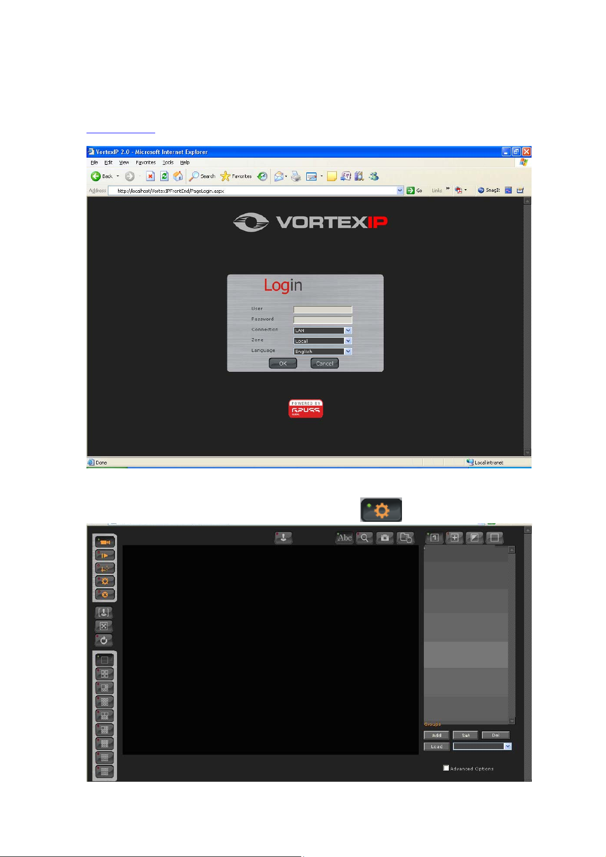
Program Access
To access the program, open Internet Explorer and in the address bar enter the following:
http://localhost
The default user name is root. By default, there is no password.
The following screen appears. In this screen, click this icon
to access the configuration.
3 of 41
Page 4
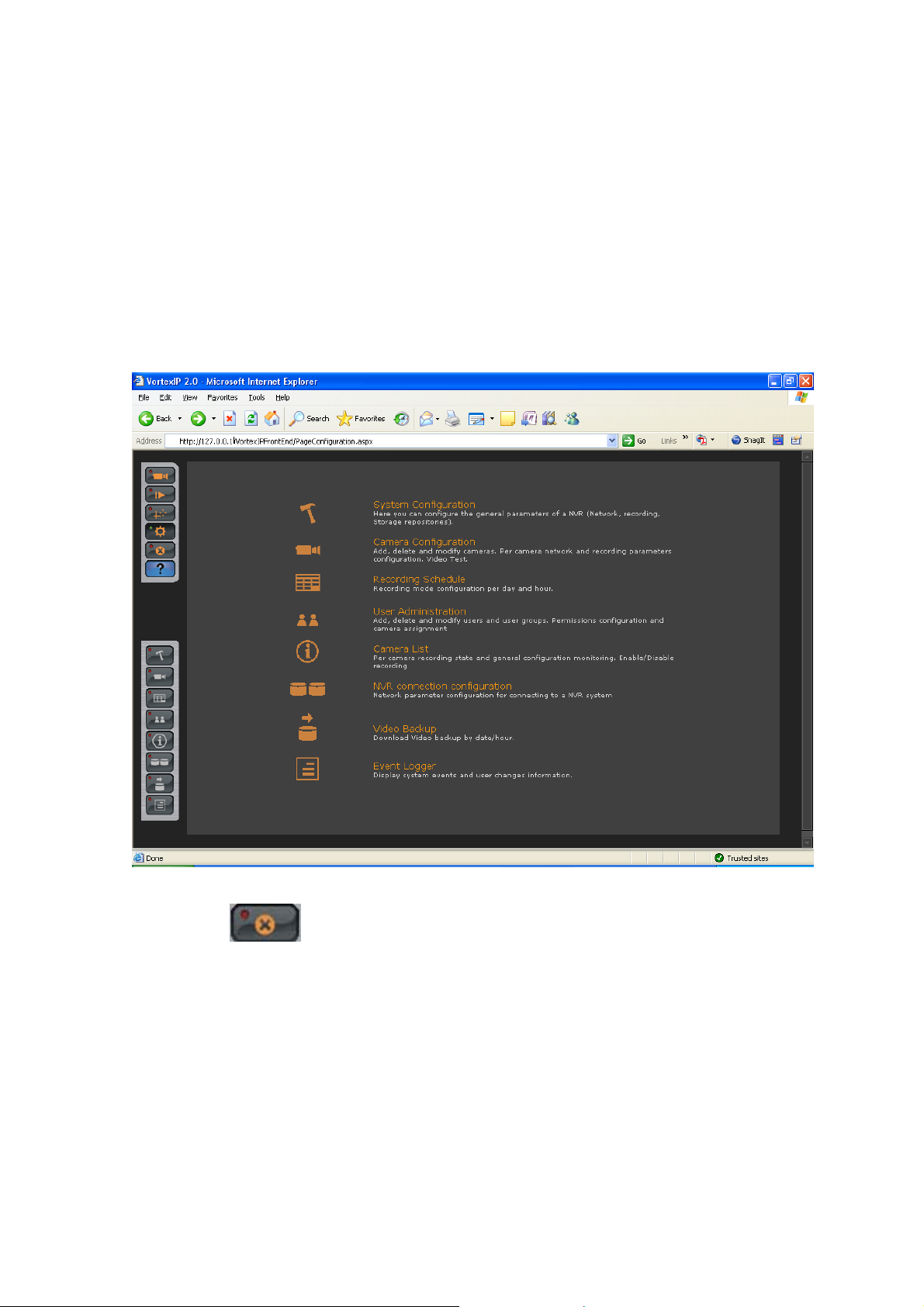
Configuration
Configuration is divided into 7 different sections:
• System Configuration
• Camera Configuration
• Recording Schedule
• User Administration
• Camera List
• NVR connection configuration
• Video Backup
Exit the system:
Click this icon
to log out the user’s session.
4 of 41
Page 5
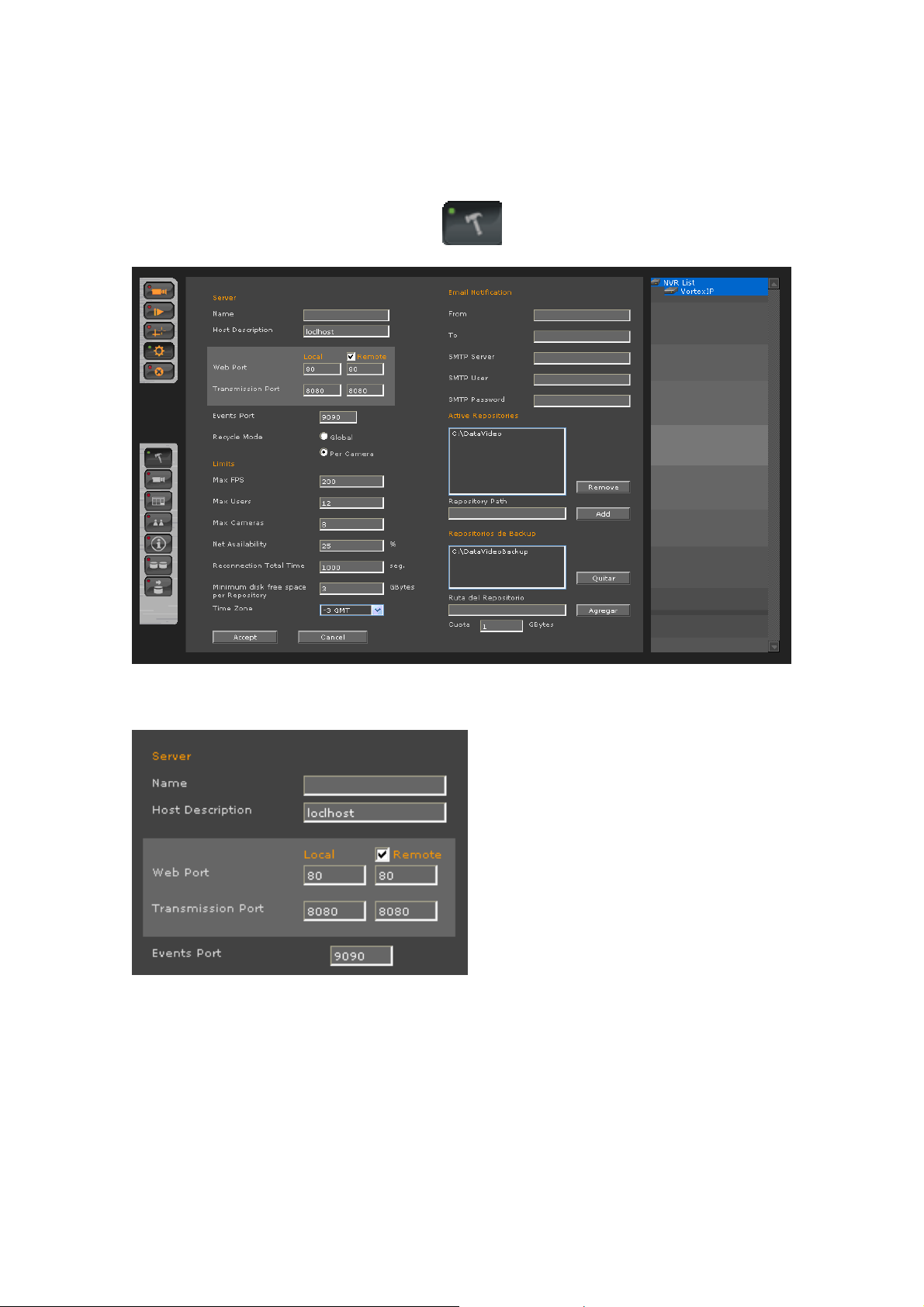
System Configuration
To access system configuration click this icon
. The following screen will appear.
Server Section
Name: Server name. The server name can be used to reference its location.
Host: Host name or server’s IP address. If “remote” is checked, the server can be managed
remotely.
Web Port: TCP port for Web server. The default web port is 80. This port can be changed but
must match with IIS (see Appendix F of this manual)
Transmission Port: TCP port which uses the server to transmit video to your remote clients.
5 of 41
Page 6
Event Port: TCP port which listens to the server to receive events from the IP cameras or video
servers previously configured. Through this port, VortexIP will notify if any event has occurred
such as motion detection and video loss.
Recycled Mode
Global: In this mode, VortexIP recycles videos from all the cameras when there is no more space
available on the repositories.
Per Camera: This mode allows the user to recycle video on a per camera basis, i.e. VortexIP
recycles the video from the camera which does not have enough available space according to the
quota configured.
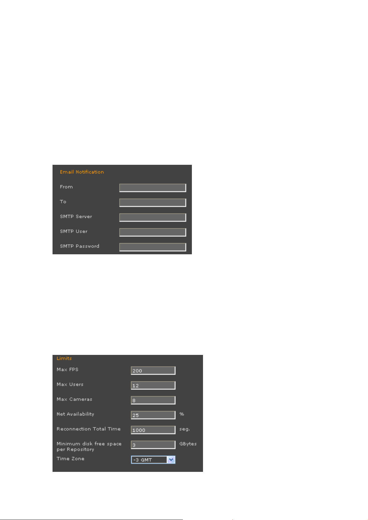
Email Notification Section
From: The sender’s address of the email notification.
To: The receipient’s address of the email notification.
SMTP server: This can be a host name or IP address. It has to be configured without
authentication.
User SMTP: User name of the account
Password SMTP: Password of the account
Section Limits
6 of 41
Page 7
Max FPS: maximum frames per second that VortexIP processes. The maximum frames per second
is 1000 per server.
Max Users: maximum number of simultaneous connections. The maximum users are 256 per
server.
Max Cameras: The maximum number of cameras is 120 cameras per server.
Net Availability: This setting must be configured with extreme care according to the quality of
the connection that it has with the cameras. If the connection with the cameras is Slow or low
quality, configure this setting near 10%. If the connection is good, you can configure this setting
near 90%. This parameter is used to distinguish how many disconnections with the camera can be
handled before reporting it as
Reconnections total time: Maximum time VortexIP will try to reconnect a camera when
connection problems occur. Once this value is reached, the camera will no longer be connected.
Minimum space for repository: This setting allows you to configure the minimum amount of
space (GB) to be reserved for each repository.
Time Zone: This setting must be configured with extreme care according to the time zone where
VortexIP recording server is installed.
disconnected
.
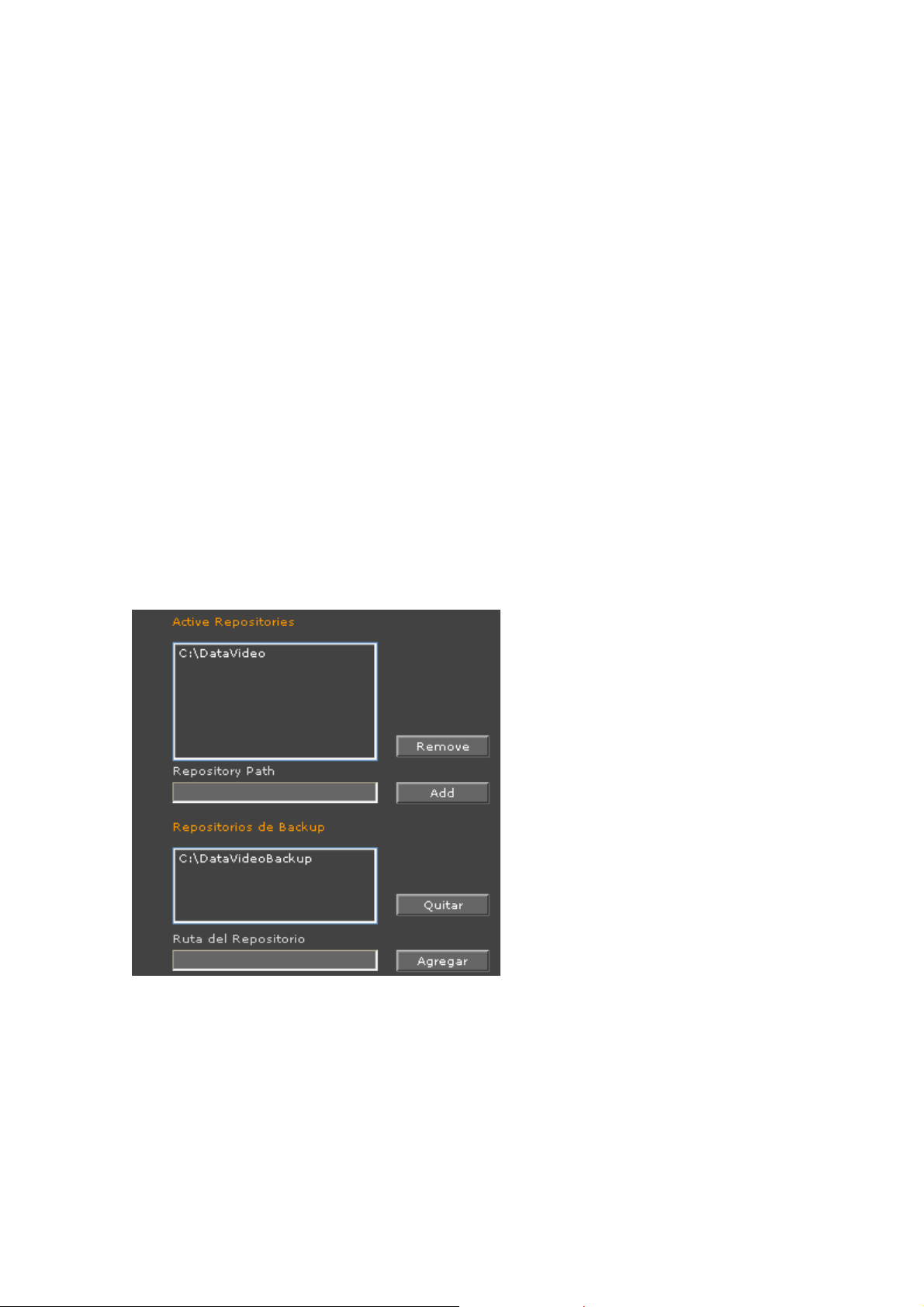
Repository
Active Repositories: Displays a list of the repositories VortexIP will be using for video recording.
The default path for the repositories is c:/datavideo.
• Remove: To remove a repository, select it and click Remove. Before removing a
repository you must first add a replacement.
• Add: To add a repository, enter the desired path, and then click Add. You may only add
repositories in the local drives.
7 of 41
Page 8
Backup Repositories: Shows the list of repositories that VortexIP uses to export video to.
• Remove: To remove a repository, select it and click remove. If you leave this field empty,
you will not be able to export video.
• Add: Enter the desired path and then click Add. You may only add repositories in the local
drives.
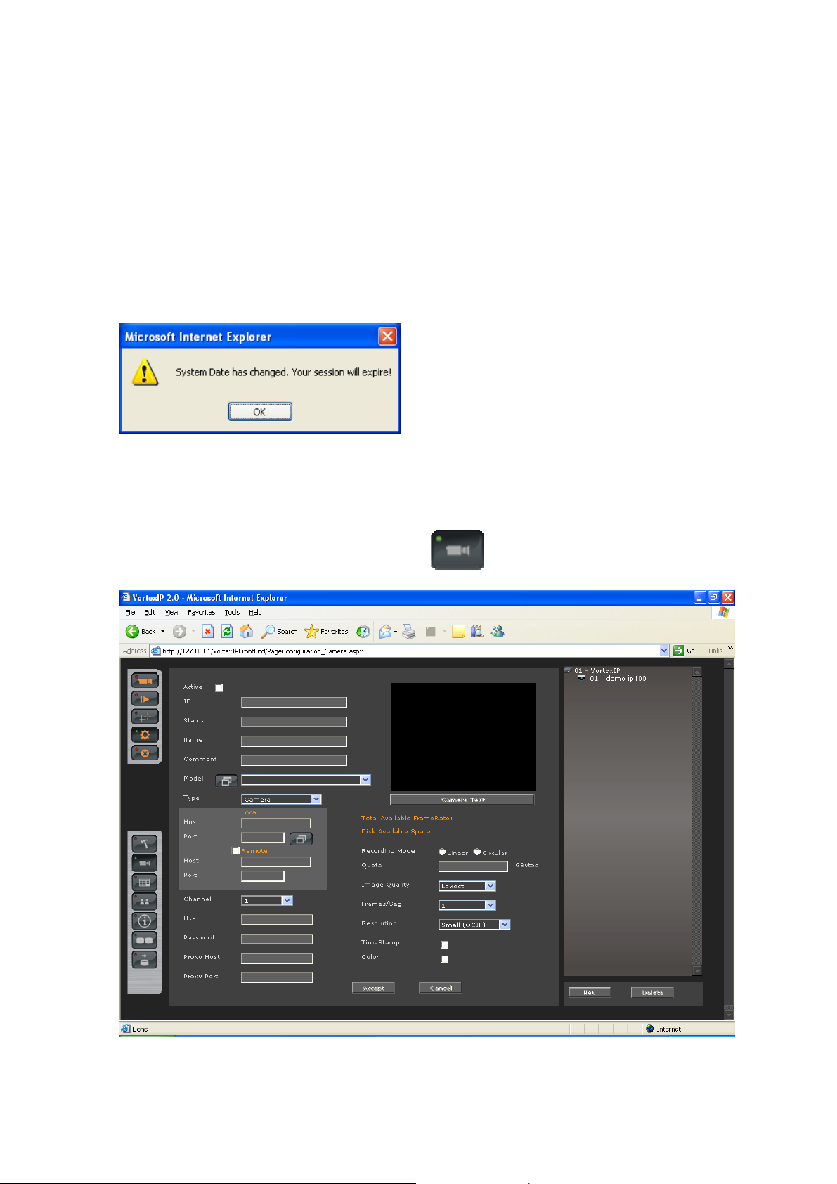
To apply changes, click Accept. Once the changes have been applied, the following message
may appear:
Once you have completed this step, you will need to login to VortexIP again.
Camera Configuration
To access Camera Configuration, click this icon
. The following screen will appear.
8 of 41
Page 9
New Camera
To add a new camera, click New on the camera tree.
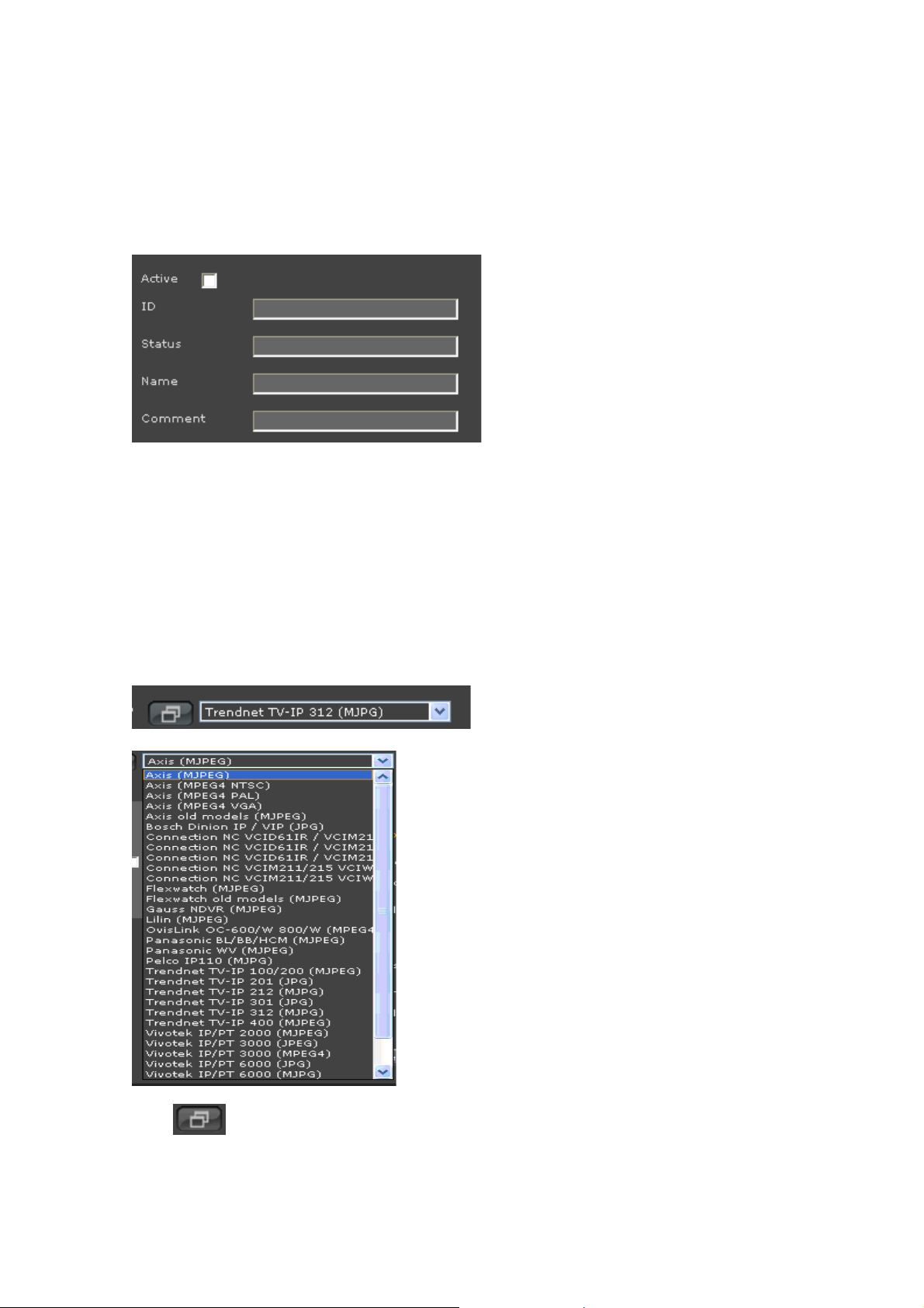
Then, enter in data related to the camera.
ID: Identification number of the VortexIP camera. Once created, you will not be able to modify it.
Remember this later for motion detection.
Status: Displays the status of the camera (i.e. Record or Stopped).
Name: Name of the camera.
Comment: Comments about the camera.
Model: Make and Model of the camera.
Press
9 of 41
Page 10
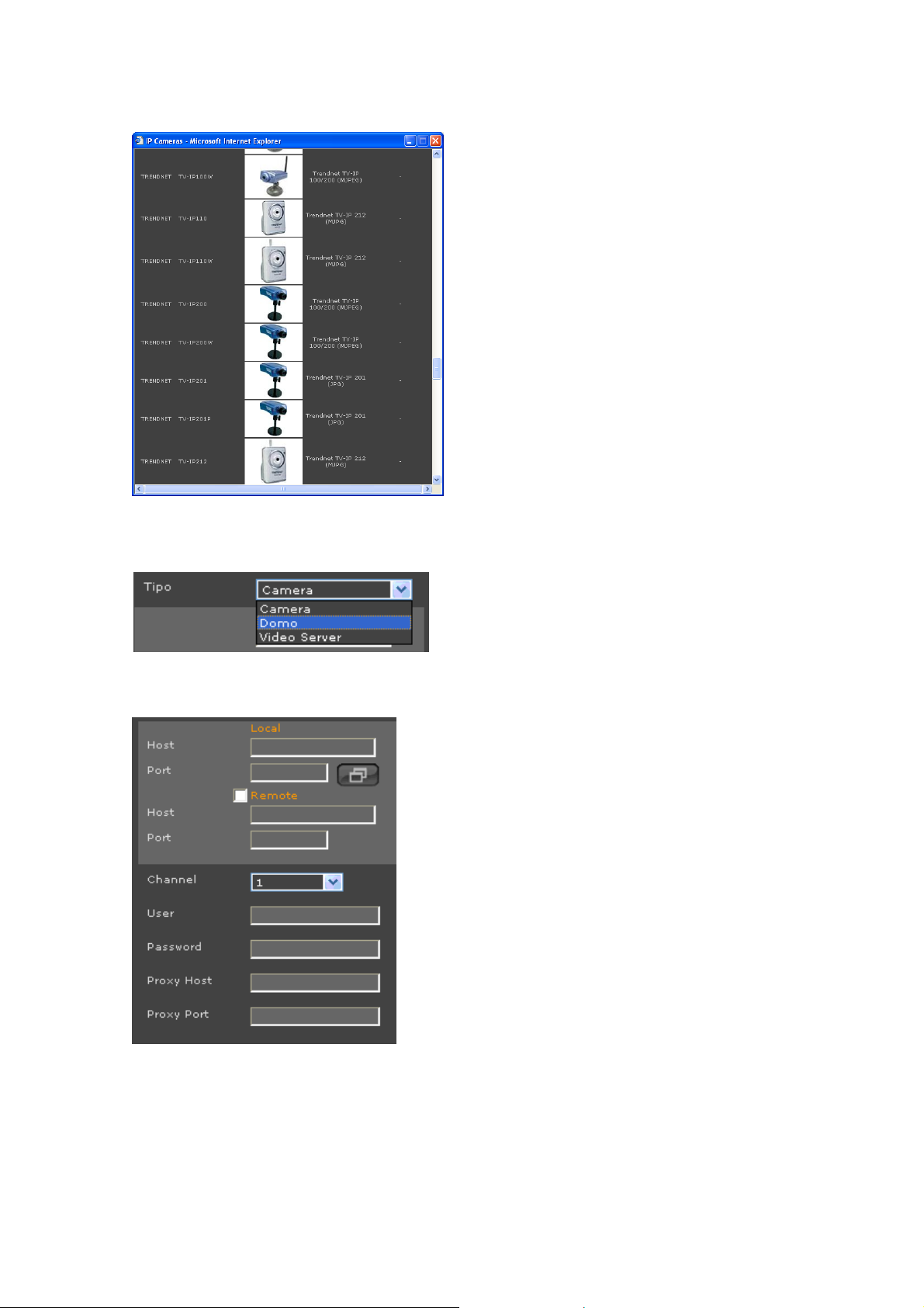
Type: Type of camera: Camera, Dome and Video Server. Dome type allows you to use Pan and
Tilt cameras.
Camera connectivity
Local:
Host: Host name or local IP address
Port: video port
If you want to view cameras remotely, check Remote.
Remote:
Host: Host name or IP local address
Port: video port
10 of 41
Page 11
MacAddess: Camera’s 12-digit Mac address.
Host Proxy: Host name or Proxy server IP address to save the camera. If there is no need to
specify any of them, leave the box blank.
Port Proxy: Proxy Server port. It is recommended you always specify a port even though it is not
going to be used to record through a Proxy Server. This parameter will be ignored if the Host
Proxy is empty.
Channel: Number of the camera’s video channel if the camera is a video server or a camera with
multiple video inputs.
User: Camera’s user name.
Password: Camera’s password.
To access the configuration settings of the camera click on the icon below:
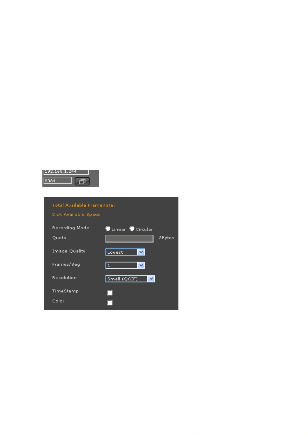
Recording Mode
Linear: VortexIP stores video from the camera unitil the quota limit stipulated has been reached
(in the event of recycle per camera) or until there is no more available space in the repositories (in
the event of global recycle). In both cases, once the storage condition has been exceeded,
VortexIP will stop recording, until the user frees enough space.
Circular: In this mode, VortexIP recycles the oldest videos if there is no more space available in
the repositories or if the quota limit stipulated for this camera has been reached (depends on the
recycled mode).
Quota: The minimum amount of space (GB) to be reserved for storing video. You only have to
take into consideration this parameter when the recycled mode is
When setting the quota, please keep the following in mind:
• Will there only be one camera or multiple cameras be installed.
Per camera
.
11 of 41
Page 12

• When you are installing the first camera, pay attention to the graphic indicating the
amount of available space. Subtract that amount by 20%. This will help avoid running
out of space.
• In the first case divide the remainder between the number of cameras that will be
installed. In the second case you should only use the remaining 50% and then divide by
the number of cameras (if the quota is less thanf 5%, it is recommended to increase the
space available by adding another hard disk).
Quality of the Image: This refers to the image compression. There are 5 levels: Lowest, Low,
Medium, High, and Highest. If you are not able to change these settings, click on the icon for the
camera.
Frames/sec: The number of frames per second. If you are not able to change these settings,
click on the icon for the camera.
Resolution: This refers to the resolution of the images. If you are not able to change these
settings, click on the icon for the camera.
Color: If you want the images in color, check this option. If you are not able to change these
settings, click on the icon for the camera.
Timestamp: Choose this image to display time and date on the image. If you are not able to
change these settings, click on the icon for the camera.
General Information
The following information will be displayed when a new camera is created. This is reported by
VortexIP server.
Frame Rate Total Available: Quantity of available FPS at the VortexIP. It helps to know how
many frames per second remain for assigning to a camera.
Available Space at the Disk: VortexIP maximum space. It helps to know how much space is
available for the camera
Delete Camera
To delete a camera, first you have to select it from the camera tree and then click Delete.
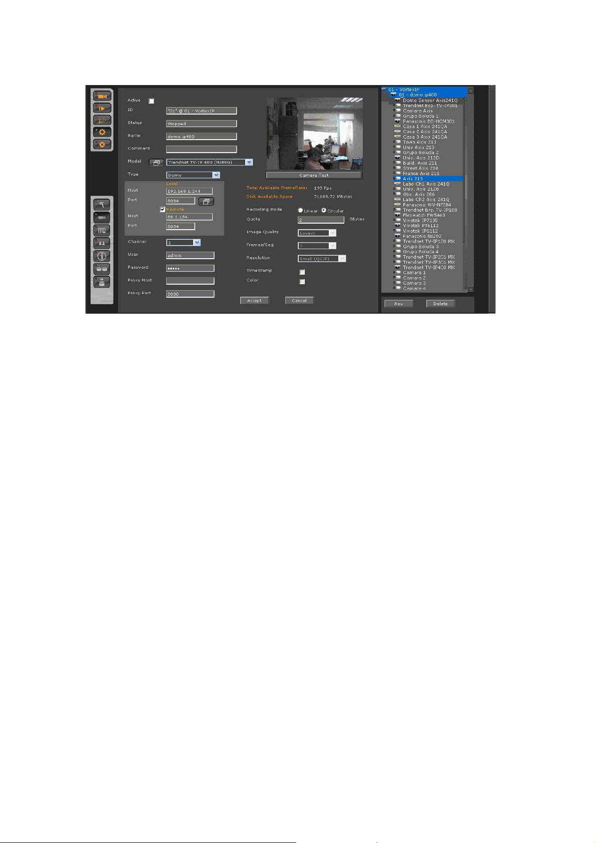
Camera Edit
To view the settings of a camera, click on one of the cameras in the camera tree. All parameters
for the camera that can be modified will appear.
12 of 41
Page 13
13 of 41
Page 14

Record Schedule
For accessing the record schedule press this button
The following screen shows the record schedule of the configured cameras.
For seeing the configuration or for changing the recording mode, first select
mode
Then, select the
And finally, use your mouse to select the desired days and times in the schedule grid.
If you click this icon
by clicking on the menu of the recording modes.
, the entire grid will be filled in for the selected recording option.
.
camera
.
Recording Modes
Continuous: It records continuously at the FPS speed previously specified.
Smart: It records continuously at FPS, and when it detects movement it increase the speed on
FPS previously specified.
Event: It records when it receives events from the IP camera. The events can be: movement
detection or other configured on the camera previously.
Disabled: It does not record.
If you keep the mouse click pressed, you will be able to paint quickly on
the grid.
14 of 41
Page 15

To apply changes press Accept.
15 of 41
Page 16

Users’ Administration
For accessing users’ Administration press the button .
VortexIP allows the creation of groups with privileges template. At the same time, inside these
groups users will be created and which their maximum privileges are those from the group,
allowing to control the scaling privileges.
Since all the users have to be part of a group, first you will have to create the group and then the
user.
The system does not allow the creation of groups containing the same name as users.
The group ‘‘wheel’’ corresponds to the administration group and by
default has complete control of the system. So, the root user belongs to
the group ‘‘wheel’’.
16 of 41
Page 17

User/Group Privileges Profiles
Live: If this option is checked, the user/group will have access to live monitoring.
Playback: If you check this option, the user/group will have access to play video only on the
assigned cameras.
PTZ: If you check this option, the user/group will have access to PTZ controls only on the assigned
cameras.
E-Map: If you check this option, the user/group will have access to visualizing the electronic map
only on the assigned cameras.
Backup: If you check this option, the user/group will have Access to making backups only, on the
assigned cameras
Export videos: If you check this option, the user/group has access to export recordings, across
media player.
Download exports: If you check this option, the user/group has access to export recordings to a
format, across media player remotely.
System Configuration: If you check this option, the user/group will have Access to read and
modify the configuration of the system.
Cameras’ Configuration: If you check this option, the user/group will have Access to read and
modify the configuration of the cameras.
Users’ Configuration: If you check this option, the user/group will have Access to read and
modify the configuration of the users.
Groups
New Group
To create a new group, press the button New Group. Then, you have to establish the group
privileges, and finally press Accept.
17 of 41
Page 18

Groups will not have a password so this field will be ignored.
Removing a Group
To erase a group, first, select the same menu for groups and then press the button Edit.
Afterwards, you will be able to press the button Erase.
Assigning Cameras to a group
First, make sure you select the group from the group’s list. Then, assign the cameras by pressing
this button >>. Then, press Accept.
Removing Cameras from a group
First, make sure you select the group from the group’s list. Then, remove the cameras by pressing
this button <<. Then, press Accept.
Users
New user
To create a new user, first, select the group to which it will be related and then press the button
New User. Then, establish the specific user’s privilege, and finally press Accept.
Removing a User
To erase a user, first, select the group where it belongs then select the user and then press the
button Edit. Next, you will be able to press the button Remove.
Assigning the cameras to a user
First, select the group where it belongs and then select the user from the user list. Next, assign the
cameras by pressing this button >>. Finally, press Accept.
Remove cameras from a user
First, select the group where it belongs and then select the user from the users’ list. Next, remove
the cameras by pressing this button <<. Finally press Accept.
Modify a user
First, select the group where the users belong. Then, select the user and press the Edit button.
User: The user’s login name.
18 of 41
Page 19

Comment: Comments about the user.
Password: The user’s password.
The only user with privileges to register, modify or remove VortexIP NVR
is root.
Remember that you have to press Save Configuration when you are sure
that you want to keep the changes made at the VortexIP data base.
List of Cameras
To access the list of cameras press this icon .
The following screen displays the list of cameras configured for recording. To enable or disable one
or more cameras, select the camera(s) from Camera Selection (you may use Shift or Ctrl for a
multiple selection) and then press the respective button.
Auto refresh: If this option is already checked then, this page will auto refresh every 30 seconds
allowing having the recording status of the cameras.
19 of 41
Page 20

Remember if y
apply the changes made at VortextIP data base.
ou select/deselect a camera you have to press Save to
NVRs Configuration
To access NVRs configuration, click this
icon
.
At the top of the screen we see the version of VortexIP and the number of licensed cameras.
New NVR
add a VortexIP Network Video Recorder (NVR) press the button New NVR.
To
Enter in data re
lated to NVR and then click Accept.
Edit NVR
o view NVR administrT
: NVR’s ID. ID
ame: NVR name. N
Host: Host name or NVR IP address.
ation setting, select on the NVR on the NVRs tree .
20 of 41
Page 21

Under Local, enter the local IP address of the server. To access the server remotely, check
emote” and enter the Public IP address.
“r
Port: VortexIP NVR’s TCP/IP administration port. By default, its port 80.
ser: VortexIP NVR user name.
U
Password: VortexIP
NVR password.
Remove NVR
To rem ve VortexIP NVR first, select it from the NVRs’ tree. Then, click Remove NVR.
o a
Remember to click Accept in order to save settings.
21 of 41
Page 22

Video Backup.
Click this icon
The following information is displayed: NVR ID, Cam ID, Camera, Export ID, Start Date, Stop Date,
Progress, File Size (if available for downloading) and Delete.
to access the Video Backup screen.
Event Logger
Display System events and user changes information. This option allows the us er to search for any
activity in the cameras or in VortexIP by date and time.
22 of 41
Page 23

Appendix A: Recording by motion detection. Events Setting
Events Reception
VortexIP has three different mechanisms to receive events from IP devices such as IP cameras, IP
video servers or third parties programs.
Events reception mechanisms supported by VortexIP are:
• TCP Event
• VortexIP receives TCP messages in a tabulated format.
• HTTP CGI Events
• VortexIP receives petitions to a CGI page and converts them into TCP events.
• SMTP Events
• VortexIP receives e-mails, processes them and converts them into TCP events.
Events are processed by VortexIP. It is necessary that it is configured correctly if you wish to
record using one of the following methods:
Event
•
•
SMTP Events
VortexIP receives the emails sent by the cameras acting as an outgoing email server.
Since SMTP is an authenticated server, NVR users have to be configured in the camera as as
follows.
SMTP data to configure in the camera are:
SMTP: <IP address or Host Name>
User: root
Password: root
Authentication: Login
: records when any event takes place.
Smart
: continuously records at 1 frame per second; when an event takes place it is
ready to record to the configured FPS value.
Syntax of the field FROM of the e-mail
In the “From” field of the e-mail, enter a valid e-mail address.
For example:
From: ndvr@ndvr.com
Syntax of the field TO of the e-mail
23 of 41
Page 24

detect
For VortexIP to
syntax:
TO: <IdCamera>.InternalVideoCaptureEvent.<Post-Alarm>@<domain.com>
Where:
<IdCamera>: The camera’s ID, for example, 207. This field can not contain any blank spaces.
<Post-Alarm>: The duration in seconds of the event’s post-alarm. This field can not contain any
blanks spaces.
<Domain.com>: The domain name with a correct syntax, for example mycamera.com, ndvr.com.
This field can not contain any blank spaces. It is not necessary for the domain to be registered or
even exist.
Example:
08.InternalVideoCaptureEvent.15@VortexIP.com
When the NVR receives an email sent to the receiving party with an email address
“08.InternalVideoCaptureEvent.15@VortexIP.com” it will generate an associated event for the
camera with ID = 08 and with a 15 seconds post-alarm.
a received email as a sent event by the camera, we must follow this
Events Notification by E-Mail – TrendNet TV-IP201/W
SMTP Configuration and sending of the Events by E-mail
To configure the data of the SMTP server on the IP camera we have to go to the menu:
“Trigger”
Enable Trigger Email: Check this option.
24 of 41
Page 25

SMTP Server address: Enter the IP address of the server that acts as a SMTP server for
receiving events by E-mail.
Sender e-mail address: Enter a valid E-mail address for the sender. For example:
“ndvr@ndvr.com”
Receiver e-mail address1: Enter the E-mail address with the syntax as explained above. For
example: 1034.InternalVideoCaptureEvent.30@ipcam.com
User name: enter root
Password: enter root
Sending Interval: Specify time between every event.
Sending Times: Specify the number of events sent.
25 of 41
Page 26

Events Notification by E-Mail– Trendnet TVIP212/312
SMTP Configuration
To configure the data of the SMTP server on the IP camera we have to go to the menu:
Event Server
SMTP Server address: Enter the IP address of the server that acts as a SMTP server to receive
events by e-mail.
Sender email address: Enter a valid E-mail address. For example,
Authentication Modes: Select SMTP
Sender user name: Enter root
Sender Password: Enter root
Receiver #1 email address: Enter the e-mail address with the syntax explained above. For
example: 1034.InternalVideoCaptureEvent.30@ipcam.com
“ndvr@ndvr.com”
26 of 41
Page 27

Event Configuration: Motion Detection
Once the SMTP server is configured, you have to configure motion detection so it can send emails
to the SMTP server. We have to go to the menu below:
Event Config
Enable: Check this option.
Schedule Profile: Select always.
Send Email: Check this option.
FTP Upload: Do not check this option.
Record to Network Storage: Do not check this option.
Save Images to USB: Do not check this option.
27 of 41
Page 28

Appendix B – Error Messages:
Access Denied
Every time that you access a resource of the systems, it will verify that you have the permission to
access it. If your user is not a root, it has restrictions to certain resources (viewing, configuration,
etc). The following screen will appear if the user does not have permission to access it:
28 of 41
Page 29

Appendix C – Problem solving
1. I am not able to watch live video nor recorded video
• Check that you have correctly installed the .NET Framework 1.1.
• Check that ActiveX components both live video and recorded video has been correctly
installed.
• Check that you have Internet access, by trying to access any known Web page
through Internet Explorer.
2. You are only able to watch live video
• Check that you have correctly installed the .NET Framework 1.1.
• Check that ActiveX component for live video has been correctly installed.
• Check you have Internet access, by trying to access any known Web Page in Internet
Explorer.
• Check that you do not have Proxy Server configured in the Internet Explorer. ActiveX
live video allows you to connect the PC through a Proxy Server. But ActiveX does not
support connections by means of a Proxy Server.
• Check that y our PC has access to the Internet.
3. ActiveX components do not get installed
• Check that you have correctly installed the .NET Framework 1.1.
4. The NVR does not record video
• Check that the NVR has direct connection to Internet and try to access any known
Web page in Internet Explorer.
• Ping the IP cameras that you want to record.
• Check that recording is enabled.
• Check the cameras’ recording schedule. If they are configured to record by event then
verify that the IP camera is sending the events to the NVR.
5. Service cannot be initialized, stopped or restarted by Web access
• This functionality is only available when VortexIP recorded is installed on Windows XP
Professional. If you are running Windows 2000 Server or Windows 2003 Server, then
you will not be able to make decisions about the recording service from the Web
access due to the security policy of the operating system.
6. Forgot my Administrator password
• For security reasons passwords will not be able to be restored. If you happen to forget
your root password, you need to reinstall VortexIP. Remember that by default, there
29 of 41
Page 30

is no root password.
7. VortexIP recorder works correctly, but whenever I want to watch a recorded
video of an event that happened less than 10 seconds ago, images do not
appear.
• VortexIP recorder has a a buffer cache to maximize the useful life of the hard drive.
Buffer’s length is by default 512Kbytes and it cannot be modified. This means that if
you are recording a camera at 1 FPS or less, then you will have to wait the equivalent
time according to the image size in Kbytes.
To view images recorded by a camera at 1 FPS you have to wait about 10 seconds,
which is the time to fill the buffer. This effect does not take place when the recording
speed is higher than 1 FPS; the time to fill the buffer becomes negligible.
30 of 41
Page 31

Appendix D – Router’s configuration
To configure port forwarding on a router so it can access VortexIP, the following considerations
have to be taken into consideration.
You need to know the following values, which can be found under system configuration:
• Web Port
• Transmission Port
• Event Port
These ports have to be accessible from remotely, as shown below:
Recorder Ports Router’s Port Forwarding
Web Port
Transmission
Events Port
The only port that has to be match is the transmission port. The Web port is necessary to
access the user’s interface. This number can be changed. The Event port is only necessary when
you want to record the cameras from the Internet.
Example:
Equipment:
TEW-672GR
Hardware Version: V1.0R
Firmware Version: 1.0.1.11, 15-August-2008
IP Address: 192.168.10.1
TV-IP422W
Hardware Version: A1.0R
Firmware Version: 1.00 Build 26
IP Address: 192.168.10.200
Server
Operating System: 2003 Server
IP Address: 192.168.10.250
Configuration:
Step 1: Log into the TV-IP422 by entering http://192.168.10.200 into a browser. The default user
name is admin with a password of admin.
Step 2: Click on “Setup” on the left hand side, click “Network” and then click “Network”.
Step 3: Enter 90 in the HTTP port field and then click “Apply”.
80 8080
9000 9000
9090 9091
31 of 41
Page 32

Step 4: Log into the TEW-672GR by entering http://192.168.10.1 into a browser. The default
user name is “admin”. By default, there is no password.
Step 5: Click “Advanced” and then click “Virtual Server”.
Step 6: Click Rule Enable.
Step 7: Enter a Rule Name (e.g. Web Port).
Step 8: Enter the IP Address for the Server.
Step 9: Select TCP for Protocol.
Step 10: Enter 8080 for Public Port.
Step 11: Enter 80 for Private Port.
Step 12: Click Add.
32 of 41
Page 33

Step 13: Click Rule Enable.
Step 14: Enter a Rule Name (e.g. Transmission Port).
Step 15: Enter the IP Address for the Server.
Step 16: Select TCP for Protocol.
Step 17: Enter 9000 for Public Port.
Step 18: Enter 9000 for Private Port.
Step 19: Click Add.
Step 20: Click Rule Enable.
Step 21: Enter a Rule Name (e.g. Events Port).
Step 22: Enter the IP Address for the Server.
Step 23: Select TCP for Protocol.
Step 24: Enter 9091 for Public Port.
Step 25: Enter 9090 for Private Port.
Step 26: Click Add.
33 of 41
Page 34

Step 27: Click Rule Enable.
Step 28: Enter a Rule Name (e.g. TV-IP422).
Step 29: Enter the IP Address for the TV-IP422.
Step 30: Select TCP for Protocol.
Step 31: Enter 90 for Public Port.
Step 32: Enter 90 for Private Port.
Step 33: Click Add.
34 of 41
Page 35

Step 34: Verify that all the ports are displayed in the Virtual Server List.
35 of 41
Page 36

Appendix E – Antivirus Configuration
VortexIP is a surveillance system, designed and optimized for Screens platform. However, it can
happen that running on the Screens platform you may find exploits, worms and vulnerabilities. For
this reason, you have to be aware that you have to protect your PC from the net.
To carry out this protection efficiently, we give you some tips to keep in mind during the
installations process of the antivirus software.
Impact on the performance
Antivirus usually impact considerably on the PC performance that is why it has to be handled
carefully on the configuration.
Since the VortexIP is designed to operate 24/7, the impact of erroneous configuration of the
antivirus on the system can cause serious problems.
If you do not have knowledge on configuring the antivirus program that you are installing, please
contact a technician or the antivirus program support for assistance.
Keys to keep in mind for the antivirus operation with the VortexIP recorder
Disable scheduled scans. The server has to be dedicated to running VortexIP.
Verify that the antivirus program or the security center does not block access and connection to
and from the NVR.
Omit scanning in real time for the following extensions: AVI, DVR, XSD, XML, and TMP
If your antivirus has the option to Optimize scanning in real time for low consumption of the CPU,
enable it.
Appendix F – Changing the Web port
The default Web port is 80. If you want to change the port number, follow these steps:
1) Access the VortexIP at the configuration page and modify the number of the desire Web
port:
2) Then you have to open the configuration file:
36 of 41
Page 37

c:\inetpub\wwwroot\VortexIPFrontEnd\web.config
Edit the following property by changing the value to the desired port number:
<add key="ServiceApplicationPort" value="80"/>
3) Configure IIS:
Start –> Control Panel -> Administrative Tools -> Internet Information Services
Then, right-click on the Default Web Site and click Properties.
37 of 41
Page 38

Modify TCP port to the desired port number.
38 of 41
Page 39

Appendix G – CMS
It is important to know the difference between CMS and Pro. The CMS has the same
functionality of Pro, but it also has the ability to remotely manage other servers with
VortexIP Pro installed. To set this up, follow these steps:
1) Go to Configuration page
2) Click on NVR connection configuration.
3) Click on New NVR, and complete all fields below and click on Accept.
4) Under the NVR List on the right, you will see the new NVR.
5) Click on Live Video
. The new NVR and cameras will now be displayed.
39 of 41
Page 40

40 of 41
Page 41

41 of 41
 Loading...