

Page 1

TABLE OF CONTENTS
INTRODUCTION……………….………………………………………..1
FEATURES…………...………………………………………………….1
PACKAGE CONTENTS……………...…………………………………1
TECHNICAL SPECIFICATIONS………...…………………………….2
SYSTEM REQUIREMENT……………………………………………..3
CABLE DIAGRAMS…………………………………………………….3
PRODUCT DETAILS……………………………………………………4
HARDWARE INSTALLATION…………………………………………5
USAGE……………………………………………………………………5
ON SCREEN DISPLAY OPERATION…………………………………9
TROUBLESHOOTING………………………..……………………….11
CERTIFICATES………………………………………………………..12
Page 2

Introduction
Thank you for purchasing TRENDnet KVM switch. KVM switch can save you MONEY, TIME, SPACE, and
UTILITY FEE by controlling multiple PCs with one set of Keyboard, Mouse and VGA Monitor.
This KVM switch is loaded with features such as 19” Rack Mount Size, Stackable (Daisy-Chain) up to eight
Switches, On Screen Display (OSD) Menu, Password security, Search PC by Name, Hot-Key Control, Front
Panel Push Buttons, and Auto Scan. It also has complete keyboard and mouse emulation for simultaneous
PCs boot-up process.
Features
??
19” rack mount size design.
?? Support Microsoft Intellimouse, Microsoft Intellimouse Explorer, Logitech Net Mouse or the other fully
compatible MS mouse.
?? Support DOS, Win3.X, Win95/98/2000/ME, WinNT, Netware, Unix, Linux and more.
??
Hot Plug - Add PCs or Rem ove Connected PCs for Maintenance without Powering Down the KVM
Switch or other PCs.
??
Very High Video Quality - Up To 1920X1440, Bandwidth: 200MHz
?? No Software Required - easy PC selection via On Screen Display Menu, Push Buttons, or Hot Keys
??
Eight characters password protection
?? Auto Scan Mode for monitoring PCs with flexible Scan time from 5~99 seconds
??
Keyboard status restored when switching PCs
?? Bank and Port Number LED Display for easy monitoring
??
Buzzer sound for switching port confirmation.
?? Using Stand ard Keyboard, VGA, and Mouse cables.
??
Dedicated Daisy -chain port
?? Auto-detect daisy -chain bank
Package Contents
Model No.: TK-400R
4 port KVM Switch 1 PCS
User’s Guide 1 PCS
AC to DC Power Adapter 1 PCS
Rack Mount Kit 1 SET
Daisy Chain Cable 1 SET
Model No.: TK-800R
8 port KVM Switch 1 PCS
User’s Guide 1 PCS
AC to DC Power Adapter 1 PCS
1
Page 3
Rack Mount Kit 1 SET
Daisy Chain Cable 1 SET
Model No.: TK-1600R
16 port KVM Switch 1 PCS
User’s Guide 1 PCS
AC to DC Power Adapter 1 PCS
Rack Mount Kit 1 SET
Daisy Chain Cable 1 SET
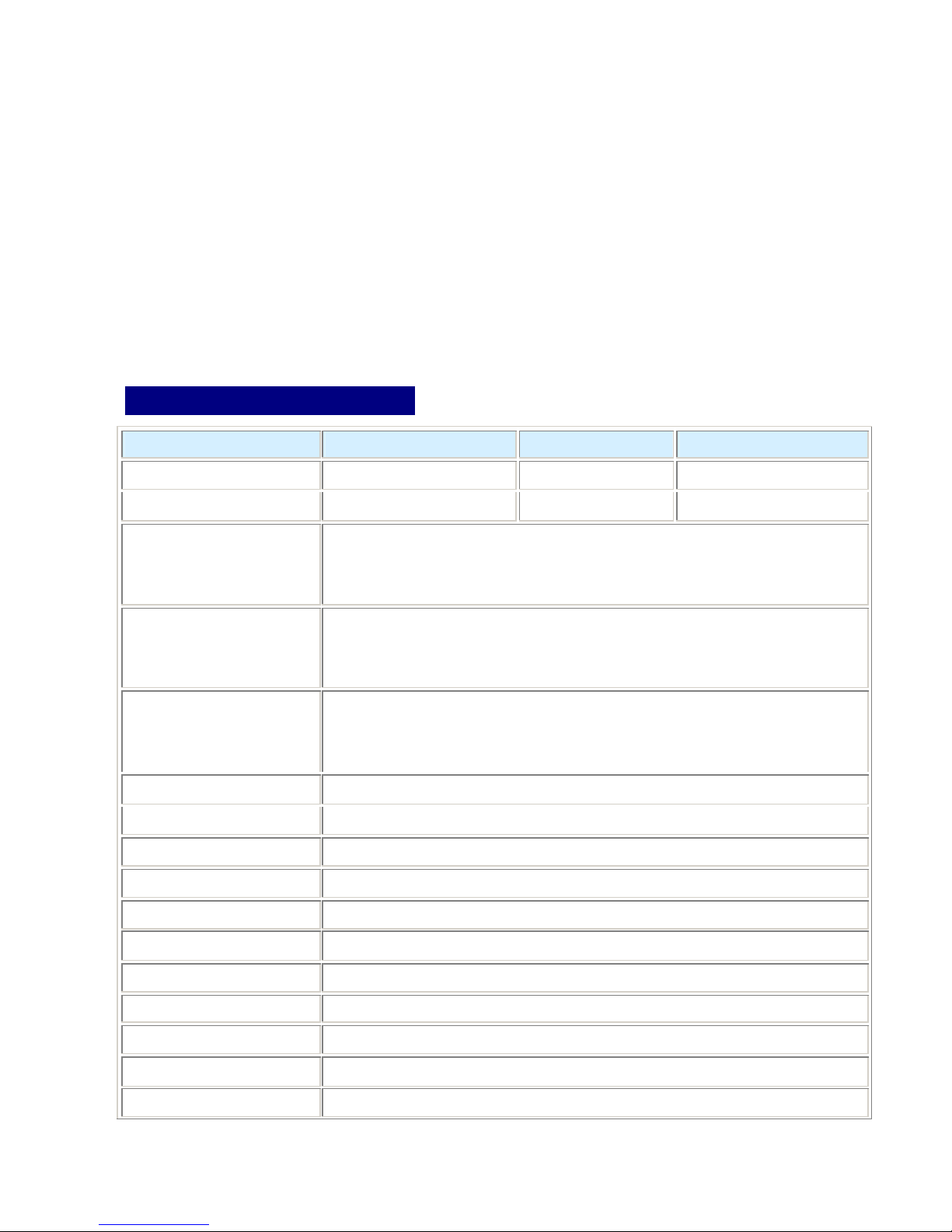
Technical Specification s
Model No. TK-400R TK-800R TK-1600R
PC Port 4 8 16
Console Port 1 1 1
PC Port Connector
(All Female Type)
Console Port Connector
(All Female Type)
Daisy-Chain Port Connector
(All Female Type)
PC selection On Screen Display Menu, Hot Key, Push Button
7 segment LED One Bank LED, Two PC Port LEDs
On Screen Display Control Yes
Auto Scan Intervals 5~99 Sec.
Keyboard Emulation PS2
Mouse Emulation PS2
VGA Resolution 1920X1440
PS/2 Keyboard mini Din 6 pin
PS/2 Mouse Mini Din 6 pin
VGA HDDB 15pin
PS/2 Keyboard mini Din 6 pin
PS/2 Mouse Mini Din 6 pin
VGA HDDB 15pin
PS/2 Keyboard mini Din 6 pin
PS/2 Mouse Mini Din 6 pin
VGA HDDB 15pin
Bandwidth 200MHz
Daisy Chain MAX Level 8 levels
Housing Metal
Power Adapter DC 12V 1A or DC 9V 1A
2
Page 4
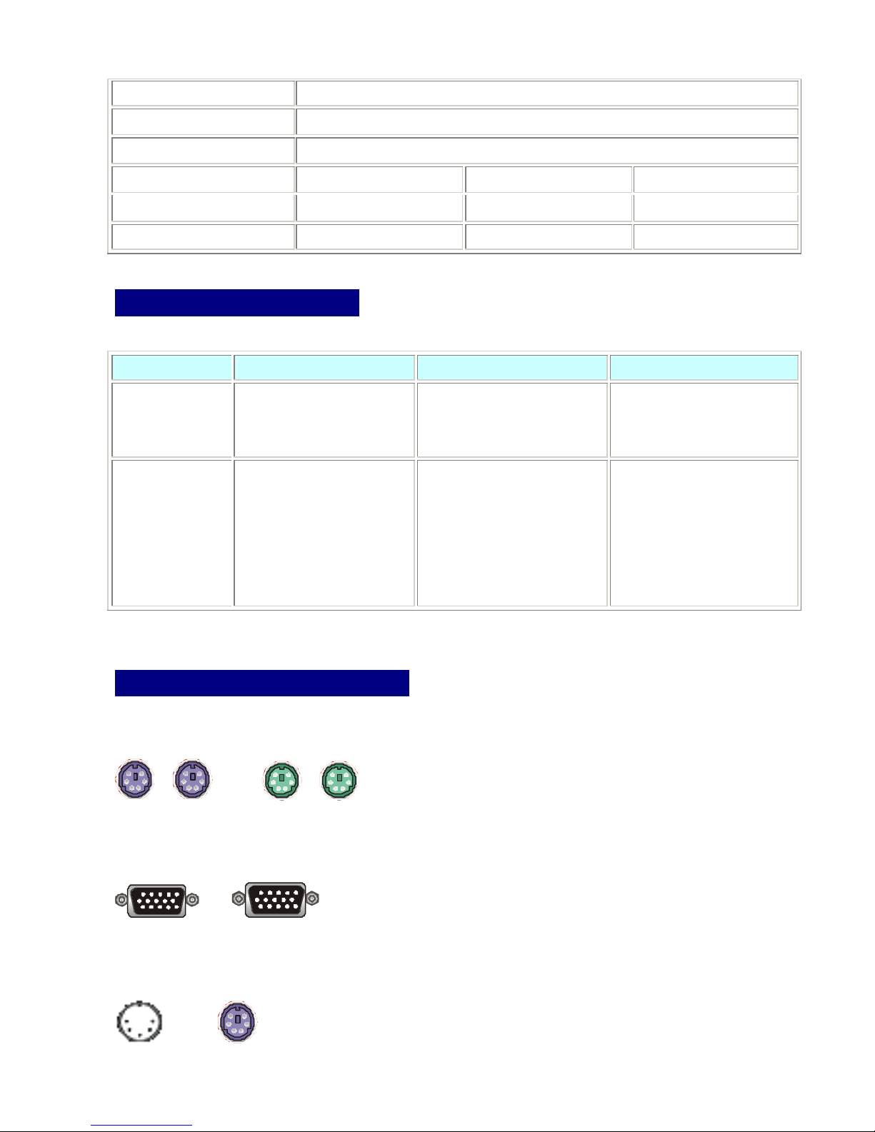
Operation Temperature 0~40?
Storage Temperature -20 ~ 60?
Humidity 0~80%, Non-Condensing
Size / Unit Height 19” Rack Mount / 1RU 19” Rack Mount / 1RU 19” Rack Mount/ 2RU
Weight (kg) 1.5kg 2.2kg 3.5kg
Dimension ( cm) 41(L) X 16.5(W) X 4.7(H) 41(L) X 16.5(W) X 4.7(H) 41(L) X 22.5(W) X 8.4(H)
System Requirements
Specifications:
Model No. TK-400R TK-800R TK-1600R
For Console Port One VGA Monitor
One PS/2 Keyboard
One PS/2 Mouse
For Computer Port 4 HDB 15 pin male -to-male
VGA cables
4 PS/2 cables male -to-male
for Keyboards
4 PS/2 cables male -to-male
for Mouse
Cable Connector Diagrams
PS/2 Cable:
Mini Din 6 pin Male to Male
VGA Cable:
HDB15 pin Male to Male
One VGA Monitor
One PS/2 Keyboard
One PS/2 Mouse
8 HDB 15 pin male-to-male
VGA cables
8 PS/2 cables male-to-male for
Keyboards
8 PS/2 cables male-to-male for
Mouse
One VGA Monitor
One PS/2 Keyboard
One PS/2 Mouse
16 HDB 15 pin male to male
VGA cables
16 PS/2 cables male -to-male
for Keyboards
16 PS/2 cables male -to-male
for Mouse
AT to PS/2 keyboard ada pter:
Din 5 pin Female to Mini Din 6 pin Male
3
Page 5
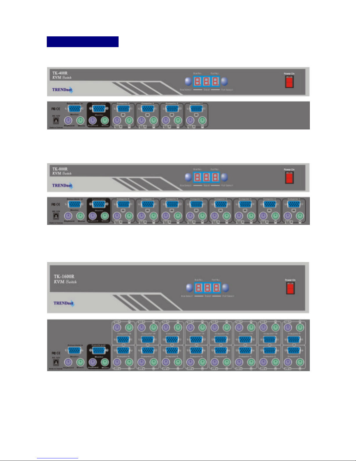
Product Details
Front Panel & Rear Panel of TK-400R:
Front Panel & Rear Panel of TK-800R:
Front Panel & Rear Panel of TK-1600R:
4
Page 6

Hardware Installation
Before installing the KVM Switch, please make sure all of peripherals and computers have been turned off.
1. Install the Switch in a fairly cool and dry place; see “Technical Specifications” section for the acceptable
operating temperature and humidity ranges. The installation site must be free from strong electroma gnetic
field generators (such as motors), vibration, dust, and direct exposure to sunlight. Install the Switch on a
sturdy, level surface that can support its weight, or in a standard EIA 19” equipment rack. To mount the
Switch on the rack, install the included mounting brackets to the sides of the Switch, secure them with the
screws, and then mount the Switch to the rack with the hardware provided by the rack manufacturer.
2. Connect the Power Adapter to the power outlet and then connect the power connector to Switch’s DC
12V jack.
3. Connect the Keyboard, VGA, and M ouse cables to the KVM Switch’s “Computer Ports” (starts from
“Computer 1” port) and the Computers’ Keyboard, VGA, and Mouse ports.
4. Connect the Keyboard, VGA monitor, and Mouse to the KVM Switch’s “Console Port”.
5. Power on the KVM Switch and the computers.
Daisy-Chain
You can daisy -chain eight TK-####R series KVM Switches together. To connect more then one TK-####R
series KVM Switches together, turn off all computers and Switches, use the included daisy -chain cable,
connect one end of the connectors to the Switches “Daisy -Chain In” Port and then connect the other end of
the connectors to the other Switches “Console Port”.
Note: Please don’t press the KVM Switch’s “Port Select” and “Bank Select” buttons or run
hot-key function when the computers are booting up.
Usage
The power on state of the KVM switch:
After powering on the KVM switch, the LED display shows “Bank No.” 1 (solid) and “Port No.” 01 (Flashing). If
there is a computer connected to “Computer 1” port, the Monitor shows the status of Computer 1 with a
“status bar” asking you to enter the password. The default password is eight zeros (i.e. 00000000). Please
key in eight zeros (by using the number keys above the letter keys) and press “Enter”, the Switch will beep
once, confirming the login, and the “Port No.” 01 LEDs will stop flashing.
If “Computer 1” port is not connected to a computer, the monitor will be blank, press the “Port Select” button
once to select the next channel (port). Keep pushing the button until the connected computer is selected and
you can then enter the password to login.
Note: Please do not change the password until you are familiar with the operation of OSD Menu. After
5
Page 7
setting the new password, the eight -zero default password will no longer work. If you forget the password, you
need to send the unit back to your distributor for factory reset. Performing the factory reset will set all the
settings in the Switch back to their default values.
The Push Buttons
“Port Select” button:
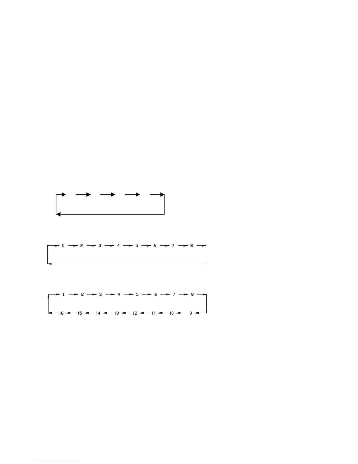
Press this button once to move from one “Computer Port” to the next (see the illustrations below).
If the Switches are daisy-chain together, only the Master KVM Switch’s “Port Select” button is functional. The
Master KVM Switch is the first Switch of the daisy -chain, it has Keyboard, Monitor, and Mouse connected to
its “Console Port”. To select different Computer Port on the Slave Switch, from the Master Switch, push the
“Bank Select” button to select the desired Slave Switch (Bank) and then push the “Port Select” button to
select the Computer Port. The “Bank No.” and “Port No.” LED Display on the Master Switch will be the same
as the LED Display on the selected Slave Switch.
TK-400R (4 Port)
1 2 3 4
“Port selection sequence”, you can keep pushing
the button to cycle through every port on the Switch.
TK-800R (8 Port)
TK-1600R (16 Port)
“Port No.” LED Indication:
When the selected Computer Port is disconnected from the PC or if the PC is not powered up, the Switch’s
“Port No.” LED will flash. When the selected Computer Port has a PC Connected to it and the PC is powered
on, the selected “Port No.” LED will stay solid.
If the Switches are Daisy -Chain together and the bank selection is at the Mater KVM Switch (Bank 1), only the
Master Switch’s Port No. LED will display numbers. All other Slave Switches’ “Port No.” LED will show -- -- .
If you push the “Bank Select” button on the Master Switch and select one of the Slave Switches, the “Port No.”
LED will display the Port Number of a port that has a computer online.
6
Page 8

“Bank Select” button:
After daisy-chaining KVM Switches together, you can push the “Bank -Select” button on the Master KVM
Switch to select different Switch Bank on the daisy-chain. The Master KVM Switch is the first Switch of the
daisy-chain, it has Keyboard, Monitor, and Mouse connect to its “Console Port”. After selecting the desired
“Bank”, push the “Port Select” button to select the desired “Computer Port”.
Note: In Daisy-Chain mode, only the Mater Switch’s Bank and Port Select buttons are functional.
“Bank No.” LED Indication:
When only one Switch is installed, this LED shows 1. If the Switches are daisy -chain together and the Bank
selection is at Bank 1 (The Master Switch), the “Bank No.” LED on the Master Switch will show 1, the second
Switch’s “Bank No.” LED will show 2, the third Switch’s “Port No.” LED will show 3… and so forth.
After pushing the “Bank Select” button to select the Slave Switch, the “Bank No.” and “Port No.” LED display
on the Master Switch will be the same as the LED display on the selected Slave Switch.
RESET
In rare occasions the Switch does not “recognize” the connected PCs properly and performing a reset (same
as power off and then on) can solve the problem. To Reset the KVM Switch, press “Bank Select” and ‘Port
Select” buttons simultaneously and then release the buttons. The Switch will beep once, the LED display
shows
connected to a live PC, the “Port No.” LED will keep flashing, push the “Port Select” button to select the next
available PC. After resetting the Switch, you will need to enter the password to login the console.
When the Switches are daisy-chain together, resetting the Master Switch is the same procedure as described
above. To reset the Slave Switch, press the Slave Switch’s Bank Select and Port Select buttons at the same
time and then release the buttons, the LED display shows -- -- --, with the “Port No.” LED (-- --) flashing.
After that, reset Master Switch, the Bank Selection will switch to the Master Switch (Bank 1), and you can
enter the password to login the console.
, the Switch then beeps again, and the LED display shows 1 01. If the “Computer 1” port is not
-- -- --
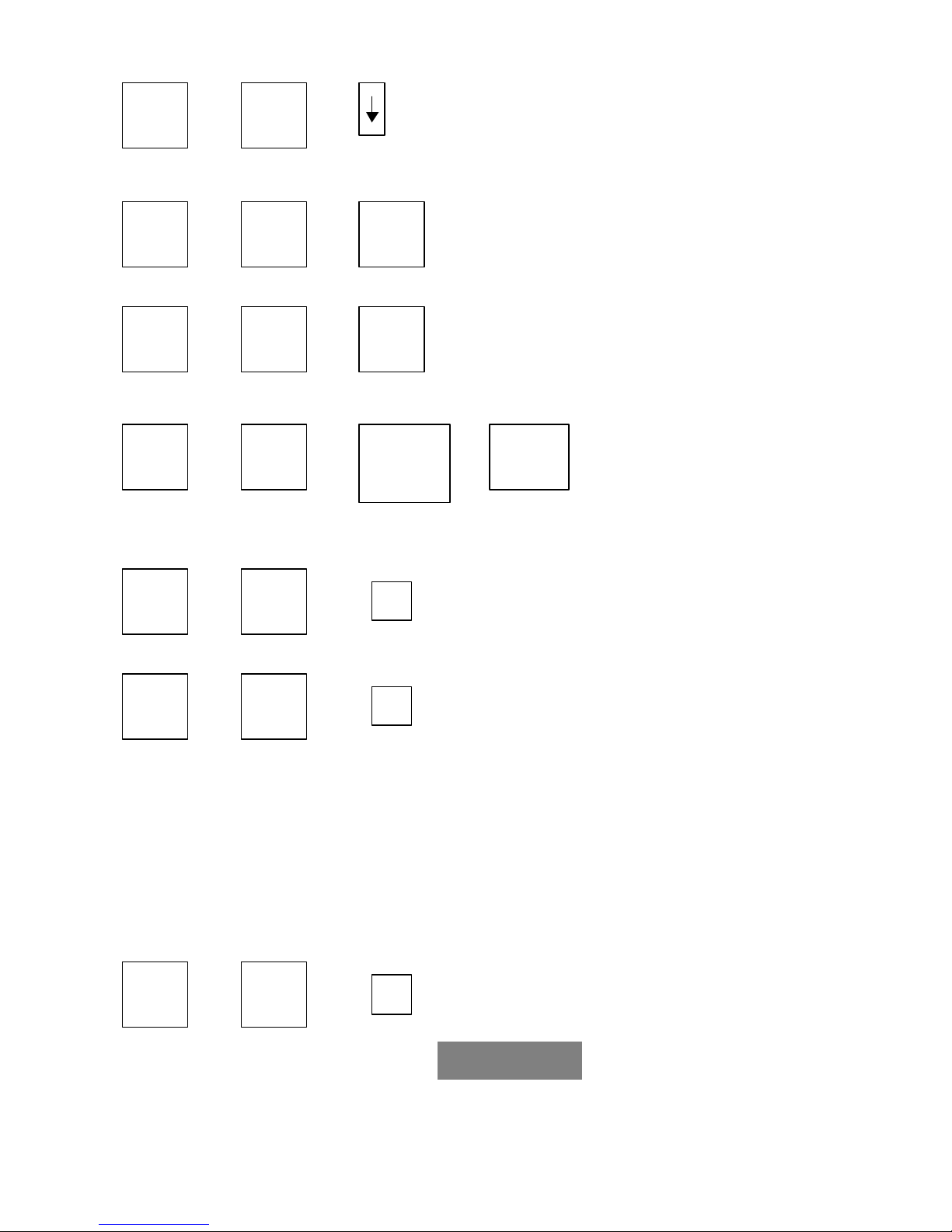
Keyboard Hot-Key Commands:
You can also conveniently command KVM Switch through simple key sequences. To send commands to KVM
Switch, the “SCROLL LOCK” key must be pressed twice within 2 seconds. You will hear a beep,
confirming that the keyboard is in hot-key mode. If you did not press any command key within 2 seconds after
entering the hot-key mode, the keyboard will return to regular Operation System Control mode.
Hot-Key Commands:
within 2 seconds
Scroll
? ? Previous Channel (Port)
Lock
7
Scroll
Lock
Page 9
S
Scroll
Note: You can also press the “up arrow key” or “down
Lock
Scroll
? ? Previous Bank
Lock
Scroll
Lock
To select PC Port in Daisy-Chain Configuration:
Scroll
? ? ?
Lock
Note: Please use the number keys above the letter keys on the keyboard to enter the bank and port
numbers.
? ?
Scroll
Lock
Scroll
Lock
Scroll
? ? Next Bank
Lock
Scroll
Lock
Page
Up
Page
Down
Bank No.
1 ~ 8
Next Channel (Port)
arrow key” again within 2 seconds from the last stroke
command to select the next or previous port.
Port No.
01 ~ 16
Note:
Port No. = 01 ~ 04 (TK-400R)
01 ~ 08 (TK-800R)
01 ~ 16 (TK-1600R)
Scroll
Lock
Note: The default is Beep Sound On
Scroll
Lock
Note: In Auto Scan Mode, the Switch will automatically scan from one computer to the other. The
Switch will “beep” once when changing from one computer port to the next. You can turn the beeping
sound off or on by pressing “Scroll Lock” key twice and then press “B”. During the scan, the Switch’s
LEDs will display the “Port No.” that it is currently monitoring. The default scan interval time is 10
seconds. You can change the time interval in OSD menu (see On Screen Display Operation below). In
daisy-chain configuration, it is possible to set different scan time interval for each Switch. When the
Switch is in Auto Scan Mode, press any key to cancel the Auto Scan Mode and the Monitor will show
the screen of the last scanned PC.
Scroll
Lock
? ? Beep Sound Off / On (for auto-scan mode only)
? ? Auto Scan Mode
? ?
Scroll
Lock
Scroll
Lock
Scroll
Lock
Note: Not including password.
B
R
Reset to OSD default value
Note: During the ROM Flash, you will see flashing on the screen and the
Master Switch’s “Port No.” LED shows “ -- -- “. The ROM Reflash process takes about 55
seconds.
8
ROM REFLASH
Page 10
OSD:
10
SEC.
CHANGE PASSWORD
SCAN:
1 0
SEC. CONSOLE
ON
/OFF
F I N D :
¦
Scroll
Lock
Note: After entering the “Find” command, the “Find” icon appears on the
screen. Enter the first few letters of the PC’s name that you wish to find
and hit “Enter”, the “Find” icon will display the first Computer on the Switch that matches the letters ,
with Bank Number and Port Number on the left hand side of the Computer Name. Press the “Up
Arrow” or “Down Arrow” key and see if there is more computer matches the letters. After finding the
desired Computer Name, hit “Enter” to view that computer. If the selected computer is not online, the
Switch will not switch to that Computer Port. If the computer is online and it is the computer that you
are looking for, press “Esc” key to cancel the “Find” mode, otherwise, use the arrow keys to select
the next computer.
Scroll
Lock
? ?
? ? Space bar On Screen Display (OSD) Menu
Scroll
Lock
Scroll
Lock
F
Find (select) PC by Name
On Screen Display Operatio n
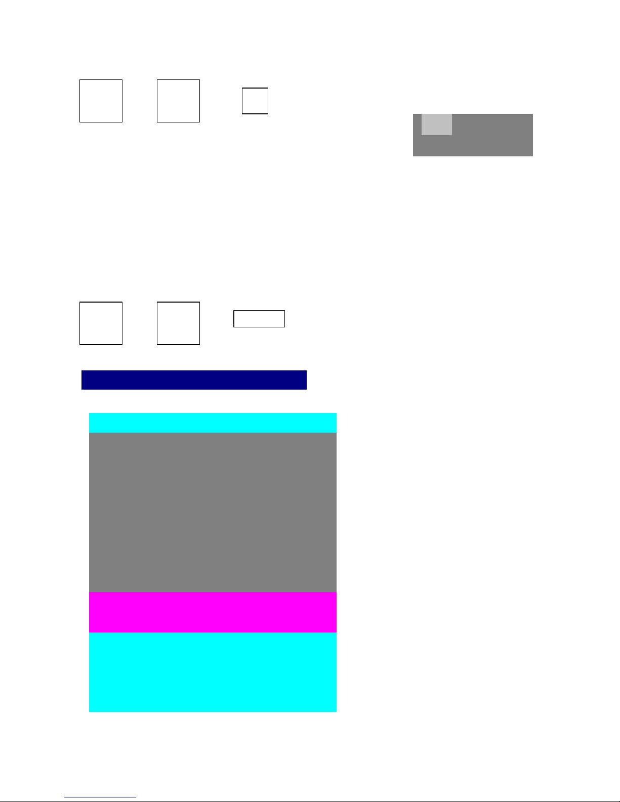
After entering the OSD Menu, the following small window (taken from TK-1600R) appears on the monitor.
a. The 1
“Page Up” or “Page Down” key to
select the “Bank” (Switch).
b. The 2nd line is the PC Name list
(the number on the left is Port
Number). You will find the Port
Number listed from 01 to 16
depends on how many ports are on
the KVM Switch. You can define
your own PC Name (maximum 10
characters), please see instructions
below. The factory default PC Name
for each port is SYSTEM ##, where
## is the Port Number. The sun
ST
line is Bank No., press
9
symbol “ ¤ “ on the left of the PC
Name means this PC is online.
Page 11

CHANGE PASSWORD
ENTER :COMPLETE
01
SYSTEM 01
02
Use up arrow key “ ? “ or down arrow key “ ? “ to select the destination PC Name. You will see a hand on
the selected Computer Name’s right hand side, pointing to the selected computer name. After you have
selected the desired PC Port, you can press the ENTER Key to switch to the selected PC Port. After finding
the PC that you are looking for, hit “Esc” key to cancel the OSD operation.
Use “ PgUp “ key or “ PgDn” key for selecting previous or next Bank Number (Switch Number).
Changing Computer Name
BANK : 1
?
After selecting the desired PC Name, press “ INS” key to edit PC name. The name can be up to 10
characters long (please use only numbers and/or letters). After finishing the name edit, press “Enter “ key to
save the information.
Navigating the OSD Menu
Use “ Tab “ key to select different Feature in OSD Menu. There are five features in OSD Menu; Computer
Name, OSD Time, SCAN Interval, CHANGE PASSWORD, and CONSOLE ON/OFF.
a. The “ OSD: 10 SEC” means that
15
OSD : 1 0 SEC. ?
SCAN: 1 0 SEC. CONSOLE ON/OFF
ESC : QUIT
TAB : NEXT INSERT :EDIT
b. The “SCAN TIME” is the scan interval time (from port to the other). The default interval time is 10
seconds and the maximum interval time is 99 seconds. To change the SCAN interval time, use “Tab”
key to select SCAN, hit “Insert”, key in the desired time, and then hit “Enter” to save. The default scan
interval time is 10 seconds.
c. To change the password, use “Tab” key to select “CHANGE PASSWORD”, hit “Enter”, enter the current
password and hit “Enter”, the “new password window” pops up.
16 SYSTEM 16
the OSD Menu last 10 seconds.
After entering the OSD Menu, if
no command is entered within 10
seconds, the Menu will disappear.
You can modify this number from
05 to 99 seconds. To change the
OSD time, use “Tab” key to select
the OSD, hit “Insert”, key in the
desired time, and then hit “Enter”
to save. The factory default v alue
is 10 seconds.
10
ESC : QUIT ENTER :
ENTER PASSWORD : ¦
Page 12

ENTER : COMPLETE
ENTER : COMPLETE
Enter the new password (maximum 8 characters; please use only numbers and/or letters) and hit “Enter”,
the “retype new password” widow appears “.
ENTER NEW PASSWORD : ¦
ESC : QUIT
RETYPE NEW PASSWORD : ¦
Retype the new password and hit “Enter”. The screen will show “New Password Complete”. Hit “Esc” to
go back to OSD Menu. Please note that the default password is 8 zeros (i.e. 00000000).
d. The “CONSOLE ON/OFF“ feature allows you to turn off (exit) the console. To do so, use “Tab” key to
select CONSOLE ON/OFF, use left arrow (? ) or right arrow (? ) key to select OFF, and then hit “Esc”.
When the CONSOLE is off, you need to enter the correct password to enter the CONSOLE. The
CONSOLE will stay ON until it is turned OFF. Performing RESET and Power off the Switch also turns
the CONSOLE off. When the CONSOLE is on, any user can use the console/OSD and change the
Switch’s configuration (except changing the password). It is recommended that you turn the CONSOLE
off after you have finished configuring the KVM Switch.
e. After entering the CONSOLE (by entering the correct password), you will see the PC Name displayed
on the monitor. You can hit “Esc” key to remove the name displayed on the screen.
ESC : QUIT
NEW PASSWORD COMPLETE
ESC : QUIT ENTER : COMPLETE
102
Troubleshooting
Precautions:
a. Ensure that all cables are well seated.
b. Label all cables properly to avoid confusion.
c. The Power Jack polarity is center positive and the power adapter output is DC12V, 1A (or DC9V, 1A).
d. Don’t press any keys on the keyboard while the computer is booting up. Otherwise, it might cause the
keyboard error or keyboard is not detected error.
1. The computer boot up fine, but keyboard doesn’t work.
??
Make sure the keyboard works when directly plugged into the computer.
?? Try a different keyboard, but use only 101, 102 or 104-key keyboard.
11
Page 13
2. The Mouse is not detected during PC boot up.
??
Make sure the mouse works when directly plugged into the computer.
?? Make sure the mouse is a true PS/2 mouse. A combo mouse will work, as long as it is set to PS/2 mode
and the correct adapter was used.
?? Avoid moving the mouse or pressing the mouse’s buttons when switching from port to port.
Avoid switching ports when the PC is shutting down.
??
?? When you switch from one PC port to another PC port, the best scan time interval is 5 seconds
or more. Normally, it takes a couple of seconds for the VGA monitor changes from one
resolution mode to another. So, it is not recommended to set the scan interval time to below 5
seconds.
CERTIFICATIONS
FCC
This equipment has been tested and found to comply with Part 15 of the FCC Rules. Operation is subject to
the following two conditions:
(1) This device may not cause harmful interference, and
(2) This device must accept any interference received. Including interference that may cause undesired
operation.
CE – Certificate
This equipment is in compliance with the requirements of the following regulations: EN 55 022: CLASS B
12
 Loading...