

Trendnet TFM-560U User Manual
○○○○○○○○○○○○○○○○○○○○○○○○○○○○○○○○○○
○○○○○○○○○○○○○○○○○○○○○○○○○○○○○○○○○○○○○○○○○○○○○○○○○○○○○○○○○○○○○○○○○○○○○○○○○○○○○○
Lo o k
E500 V.90 USB MODEM USER’S MANUAL
TABLE OF CONTENT
1. Contents of Package
2. Comprehensive Modem Installation Instructions
2.1 System Requirements.................................2
2.2 Hardware Installation...............................2
2.3 Setup Instructions for Windows 98...........3
E500 V.90 USB MODEM USER'S MANUAL
2.4 Testing your modem.................................6
2.5 Monitor Application of USB modem.............7
2.6 Install Communication Software...............9
3. T roubleshooting
Appendix 1: Modem Specifications...........................11
Appendix 2: Modio AT Command Sets......................12
TM
Appendix 3: Government Compliance notices................37
○○○○○○○○○○○○○○○○○○○○○○○○○○○○○○○○○○○
P.1
○○○○○○○○○○○○○○○○○○○○○○○○○○○○○○○○○○○○
38
○○○○○○○○○○○○○○○○○○○○○○○○○○○○○○○○○○
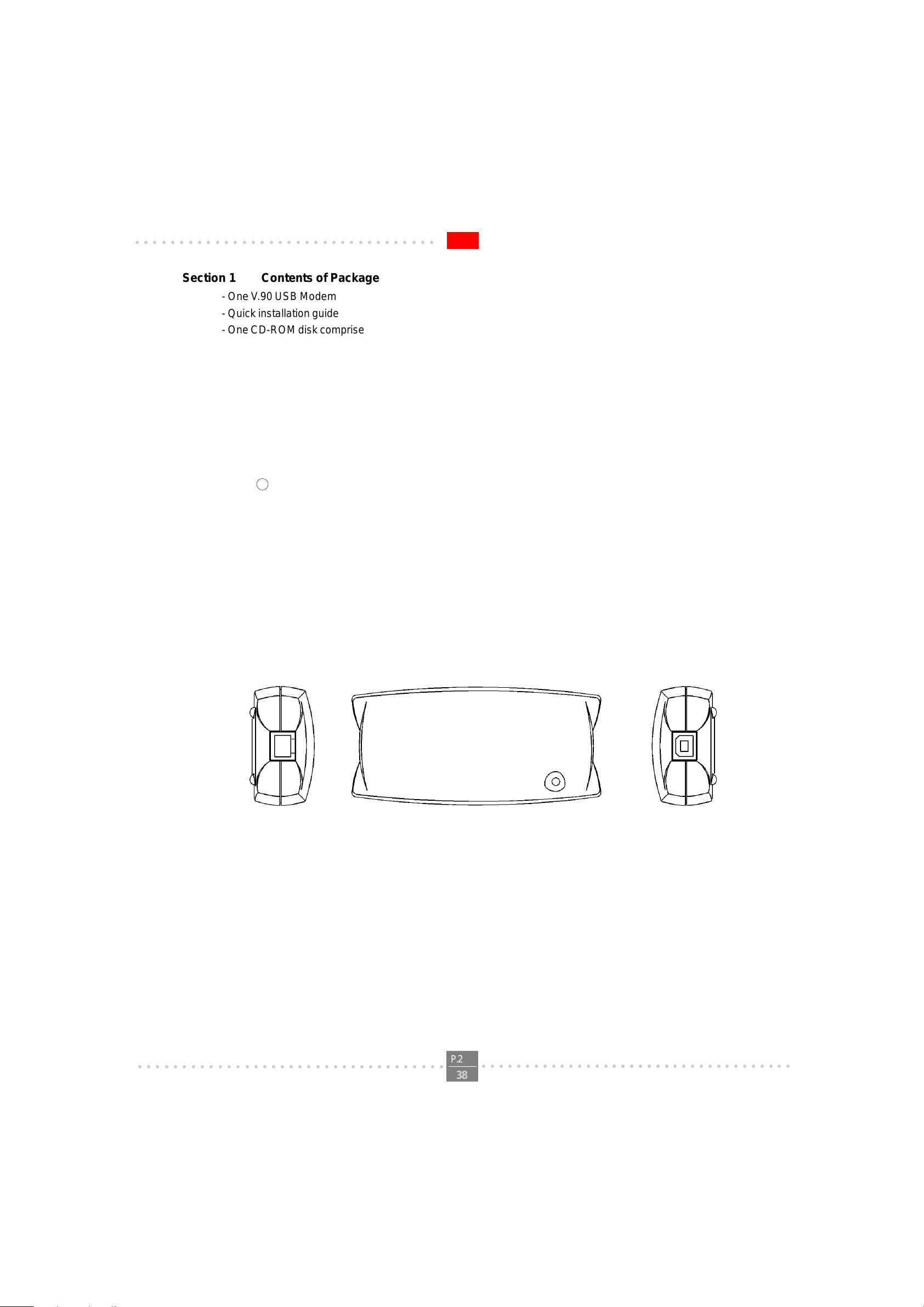
Section 1 Contents of Package
- One V .90 USB Modem
- Quick installation guide
- One CD-ROM disk comprises Communication software, Modem Driver & User's Manual
- One T elephone Cable
- One USB Cable
Please contact the place of purchase if any of the above listed items are missing.
Section 2 Comprehensive Modem Installation Instructions
Section 2.1 System Requirements
The modem operates on a personal computer equipped with the following:
- Pentium 166MMX or faster CPU ( 200 MHz recommended )
- 16 MB RAM
- USB port
- Windows 98 or Windows NT 5.0 operating system
R
E500 V.90 USB MODEM USER'S MANUAL
Section 2.2 Hardware Inst allation
Please refer to Fig. 2 - 1 and proceed to following steps for how to connect your modem to the computer and with USB
port and telephone wire.
Phone Jack
FIGURE 2-1 V .90 USB modem diagram
1. Plug one end of USB cable into the “USB” jack on your PC.
Plug another end of USB cable into the USB jack at the V .90 USB modem.
2. Plug one end of telephone cord into the telephone jack at the V.90 USB modem.
Plug another end of the telephone cord into the telephone wall jack.
3. Up to now, the hardware installation has been finished. If you have not encountered any problems, you can
go to Section 2.3 System Setup. If you are having problems, see Section 3 Troubleshooting.
USB Jack
NOTE : The telephone wall jack you use must be for an ANALOG phone line (the type found in most homes). Many
offices are equipped with digital phone lines. Please be sure you know which type of line you have. The modem will be
damaged if you use a digital phone line.
○○○○○○○○○○○○○○○○○○○○○○○○○○○○○○○○○○○
P.2
○○○○○○○○○○○○○○○○○○○○○○○○○○○○○○○○○○○○
38

○○○○○○○○○○○○○○○○○○○○○○○○○○○○○○○○○○
Section 2.3 System Setup
Section 2.3.1 Setup instructions for Windows 98
STEP 1. After you complete the modem hardware installation . Windows system will automatically detect your
new added devices.Windows system will then prompt you with a Add New Hardware Wizard screen
as shown in figure.
E500 V.90 USB MODEM USER'S MANUAL
Then click on Next.
STEP 2. A prompt screen will ask you to select “search for the best driver for your device” or display a
list of all the drivers in a specific location, so you can select the driver you want. Please select the
recommended one as shown in figure.
Then click on Next
○○○○○○○○○○○○○○○○○○○○○○○○○○○○○○○○○○○
P.3
○○○○○○○○○○○○○○○○○○○○○○○○○○○○○○○○○○○○
38

○○○○○○○○○○○○○○○○○○○○○○○○○○○○○○○○○○
STEP 3. And then, a prompt screen will ask you to indicate where your driver is located, “floppy disk drives”,
“CD-ROM drive”, “Microsoft Windows Update” or “specify a location:”. Please select “CD-ROM
drive” as shown in figure.
Insert the Modem Driver CD-ROM disk attached with your modem into the CD-ROM drive device
then click on Next.
STEP 4. Then, a prompt screen indicates Windows has found the best driver for your modem as shown in
figure.
E500 V.90 USB MODEM USER'S MANUAL
Please make sure the source of your driver is correct then click on Next.
STEP 5. Click on Finish to complete the modem installation.
Windows will detect again a New Hardware and will install the modem driver.
○○○○○○○○○○○○○○○○○○○○○○○○○○○○○○○○○○○
P.4
○○○○○○○○○○○○○○○○○○○○○○○○○○○○○○○○○○○○
38
○○○○○○○○○○○○○○○○○○○○○○○○○○○○○○○○○○
STEP 6. The system will prompt another Add New Hardware Wizard screen with the phrase Wave
Device for Voice Modem. Please remain the Modem Driver CD-ROM disk attached with
your modem in the CD-ROM drive device D:\. Then go through the above STEP 2 to STEP 5 again.
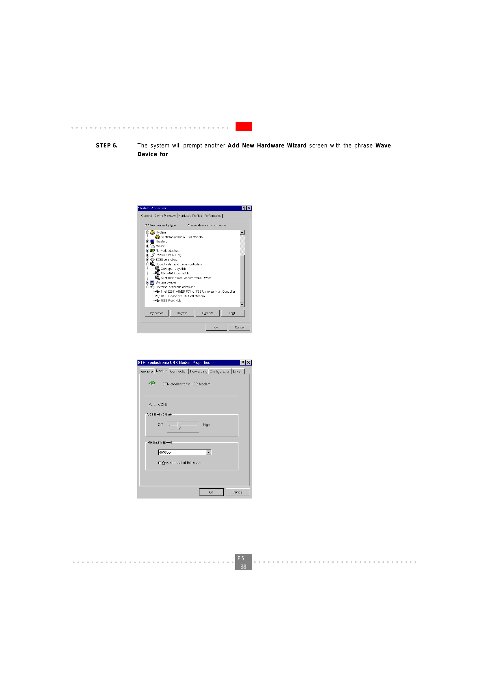
STEP 7. At the end of this installation process,the Device Manager tab of the System Properties will
show the addtion of STMicroelectronic USB Modem in the Modem section and USB Device of
STM Soft Modem in the USB section.
E500 V.90 USB MODEM USER'S MANUAL
STEP 8. Double click the STMicroeletronic USB Modem and choose the Modem tab as shown below .
Make sure that the Maximum speed is set to 460800.
○○○○○○○○○○○○○○○○○○○○○○○○○○○○○○○○○○○
P.5
○○○○○○○○○○○○○○○○○○○○○○○○○○○○○○○○○○○○
38

○○○○○○○○○○○○○○○○○○○○○○○○○○○○○○○○○○
STEP 9. (OPTIONAL)
Please check the back of your USB Modem if there are “CTR21” label and serial label like the figure
below.
Please Set your country setting at “CTR21-EUROPE” for pan-Europe Usage.
E500 V.90 USB MODEM USER'S MANUAL
STEP 10. If there was no error message while installation process is finished,your modem has been
set up properly and finctionally .
Section 2.4 T esting Your Modem
Before you set up your software, start with a quick test to check that your modem is working. Once you have
determined that your modem is setup properly , go on to Section 2.6 Install Communication Sof tware to install your
communications software. If you are having problems, see Section 3 T roubleshooting.
Click on Start and point to Setting. Then click on Control Panel. When the Control Panel window opens. Scroll down
to the Modem icon and double click on it. Click on the Diagnostics tab and highlight the COM port for your modem.
Then click on More Info, your computer will automatically communicate with your new modem using A T commands and
receiving responses from your modem. A list of response means the modem is setup properly.
○○○○○○○○○○○○○○○○○○○○○○○○○○○○○○○○○○○
P.6
○○○○○○○○○○○○○○○○○○○○○○○○○○○○○○○○○○○○
38

○○○○○○○○○○○○○○○○○○○○○○○○○○○○○○○○○○
Section 2.5 Monitor Application of USB modem
Y ou will find the icon of the Monitor of STMicroelectronic USB modem at T ask List while you have succed to
dialup your ISP or RAS with your STMicroelectronic USB modem.
Click on the icon
Then, a screen display the linking speed and some information of modem in Status tab as
shown in figure.
E500 V.90 USB MODEM USER'S MANUAL
Click on Advanced tab. It will show more detail information of communication protocol as
shown in figure below .
○○○○○○○○○○○○○○○○○○○○○○○○○○○○○○○○○○○
P.7
○○○○○○○○○○○○○○○○○○○○○○○○○○○○○○○○○○○○
38
○○○○○○○○○○○○○○○○○○○○○○○○○○○○○○○○○○
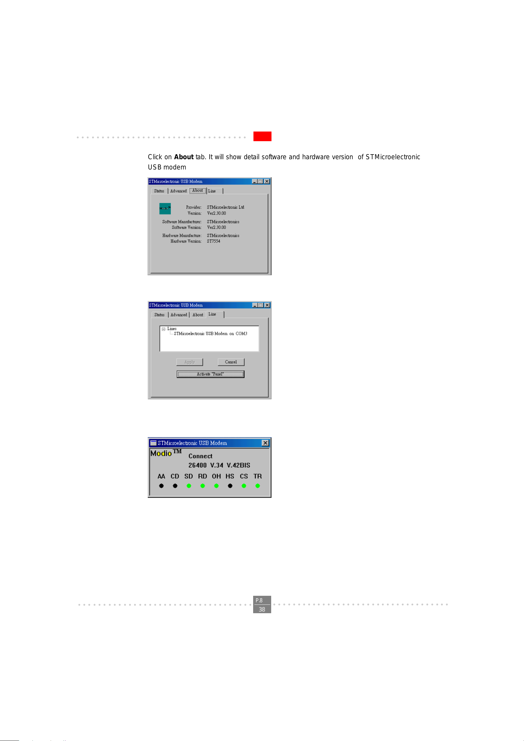
Click on About tab. It will show detail software and hardware version of STMicroelectronic
USB modem as shown in figure below .
Click on Line tab.It will show connecting modem of phone line as sown in figure below .
E500 V.90 USB MODEM USER'S MANUAL
Click on Activate “Panel” button. It wiil open signal monitor of USB modem as shown in
figure below .
○○○○○○○○○○○○○○○○○○○○○○○○○○○○○○○○○○○
P.8
○○○○○○○○○○○○○○○○○○○○○○○○○○○○○○○○○○○○
38

○○○○○○○○○○○○○○○○○○○○○○○○○○○○○○○○○○
Section 2.6 Install Communication Software
Y ou can install the communication software from the CD-ROM disc attached with your new modem. Please consult the
software manual in the CD-ROM disc for the detail of software installation.
Y ou do not have to use the communication software attached with your new modem. The modem was designed for and
tested using a wide range of communications software packages. Many communication applications identify the modem automatically and configure themselves for the correct operating settings. Some of the communication applications will ask you to select the type of modem you are using. Select a Generic Fax class 1 modem will let you use
basic communication and fax functions.
Section 3 T roubleshooting
Your modem is designed to provide reliable and trouble-free functionality, however, should you experience any
difficulty , the information contained in this section will assist you in determining and resolving the source of the problem.
Problem: Modem does not respond to A T commands
Possible solutions:
1. Make sure the modem is not configured with a conflicting COM port and IRQ setting. Make sure the
communication software is configured with the correct COM and IRQ settings (the same COM port
and IRQ as the modem). Your communications software will not be able to send or receive any data if it is not
configured to match the COM port and IRQ settings for the modem.
E500 V.90 USB MODEM USER'S MANUAL
DOS based communication program is not working with this modem neither can you operate the
modem in MS-DOS prompt screen.
2. Make sure the modem is properly initialized using the driver software. The software may improperly initialize
your modem because you have selected an incorrect modem type. You may also be prompted to enter an
initialization string by the software. Use AT&F as your initialization string.
Problem: Modem dials but does not connect
Possible solutions:
1. Be sure the IRQ setting and USB port is identical on the modem and the software.
2. Make sure that the phone line is working properly . A noisy line will prevent proper modem operation.
Problem: Modem makes a connection but no data appears on screen
Possible solutions:
3. Make sure all communication parameters (baud rate, data, stop, and parity bits) are properly configured and
are identical on both sides. Be certain hardware flow control (RTS/CTS - default) is enabled in both the
modem and the communication software.
4. Press the ENTER key several times. The remote system may be waiting to receive your data before it begins.
5. Make sure the correct terminal emulation mode is being used in the software (refer to software manual).
Problem: Modem displays errors while on-line with a remote modem
Possible solutions:
6. Make sure Call Waiting is turned off.
7. Make sure RTS/CTS hardware flow control is enabled (do not use XON/XOFF software flow control when
transferring binary files).
○○○○○○○○○○○○○○○○○○○○○○○○○○○○○○○○○○○
P.9
○○○○○○○○○○○○○○○○○○○○○○○○○○○○○○○○○○○○
38

○○○○○○○○○○○○○○○○○○○○○○○○○○○○○○○○○○
8. Make sure the data speed is not faster than your computer capability . Operating too many applications at the
same time may cause communication problem. Close unnecessary application in your System.
Problem: Modem exhibits poor voice recording or playback
Possible solutions:
9. Make sure the correct modem type is selected in the Voice/FAX software. Volume adjustment is available in
control panel.
10. Make sure your computer is fast enough to handle voice operations (38.4 Kbps). V oice operations are CPU
intensive and require a better CPU sharing when running under Windows.
Problem: No dial tone
Possible solutions:
11. Ensure that the telephone cord it securely connected at both modem and wall outlet.
12. Unplug the telephone cord from the computer and connect it directly to a telephone from the wall outlet.
Check for a dial tone. If there is none, the problem is in the telephone cord or system. Call your telephone
service provider.
13. Double-check your country setting. Different country setting will cause different modem performance.
Please select the correct country as you located.
14. Check modem performance with a direct line from your telephone company. Some PBXs may cause the
telephone line condition change and affect modem performance.
E500 V.90 USB MODEM USER'S MANUAL
Problem: The modem does not answer incoming calls
Possible solutions:
15. Ensure that the automatic answer parameter is set to one of the enabled options, using the ATS0 command
(A TS0=1 to answer af ter one ring, and so on).
16. Ensure that no other devices, such as fax or answering machines, are answering calls before the modem
does.
If you can not resolve your situation after reading this section, contact your dealer or vendor for assistance.
○○○○○○○○○○○○○○○○○○○○○○○○○○○○○○○○○○○
P.10
38
○○○○○○○○○○○○○○○○○○○○○○○○○○○○○○○○○○○○

○○○○○○○○○○○○○○○○○○○○○○○○○○○○○○○○○○
Appendix 1 Modem Specifications
Data Protocols:
- V.90, V.34, V.32bis, V.32, V.22bis, V .22, V.21, V.23, Bell 212A, Bell 103
Data Speed:
56000, 54666, 53333, 52000, 50666, 49333, 48000, 46666, 45333, 44000, 42666, 41333, 40000, 38666,
37333, 36000, 34666, 33333, 32000, 30666, 29333, 28000, 26.4k,24k, 21.6k, 19.2k, 16.8k, 14.4k, 12k,
9600, 7200, 4800, 2400, 1200, 300
Data Compression
- V .42bis, MNP5
Error Correction
- V .42 LAPM, MNP2,3,4
Fax Protocols:
- Group 3 Compatible, Class 1 fax: V.17, V.29, V.27ter, V.21
Fax Speed:
- 14.4k, 12k, 9600, 7200, 4800, 2400, 300
General:
St andard AT commands
V .8 and Automode
V .80
Virtual UART (460.8kpbs)
DTMF detection and generation
Wake-up on ring
OnNow Power Management
Low power consumption
Virtual DTE
Distinctive ring for data/fax/voice (by communication software)
World wide country support
Answering machine (voice)
E500 V.90 USB MODEM USER'S MANUAL
○○○○○○○○○○○○○○○○○○○○○○○○○○○○○○○○○○○
P.11
38
○○○○○○○○○○○○○○○○○○○○○○○○○○○○○○○○○○○○

○○○○○○○○○○○○○○○○○○○○○○○○○○○○○○○○○○
Appendix 2 ModioTM AT Commands Sets
Modem operation is controlled by A T commands. These A T commands include the following:
- Basic AT commands, for example ATDT123
- Extended A T Commands for example A T&E,A T\A,A T%C,AT+MS
- S-Register commands, for example A TS0=1
- Fax Class 1 commands, for example A T+FTM
- Voice commands, for example A T#VTX
The command syntax and operation guidelines for each command category are described in the following sections.
A command line is a string of characters sent from a DTE (Terminal or Data Terminal Equipment) to the DCE while
the DCE is in command state. Command lines have a prefix, a body and a terminator. The prefix consists of the
ASCII characters AT or at . The body consists of printable ASCII characters. Space characters other than <CR>
(See register S3), and <BS> (See register S5) are ignored. <CR> is command terminator.
Characters preceding the AT prefix are ignored.
AT Command Guidelines:
E500 V.90 USB MODEM USER'S MANUAL
- Basic AT commands consist of single ASCII characters, which may be preceded by a prefix character, for
example &, and followed by a decimal number, for example AT&W1.
- Missing decimal parameters are interpreted as 0. For example, if you type ATH , the command ATH0 is
assumed.
- Fax commands are preceded with the +F characters and terminated by semicolon (;) or <CR> character.
- The modem supports editing command lines by recognizing the <BS> character.
- The AT command sequence may be followed by any number of commands in sequence, with the exception of
commands Z, D or A, where all characters following on the same command line will beignored.
- When a syntax error is found in the command line, an ERROR response will be returned to the DTE.
Execution of commands D and A will be aborted if another character is entered before completion of the hand
shake.
- When the modem has entered on-line data mode, it is possible to break the data transmission in order to is
sue more AT commands. This is done by the DTE sending a sequence of three escape characters (defined in
S2, ‘+’ by default).
The modem will comply with the commands listed below. Parameters applicable to each command are listed below .
Default factory configuration settings are marked by an asterisk *.
Features marked with (-) are not yet available in current version of Modio.
Basic A T Commands
A/ Re-execute Command
The modem repeats the last command line sent by the DTE. Usually used for re-dialing.
Note: This command should not be terminated by <CR>.
A Answer
○○○○○○○○○○○○○○○○○○○○○○○○○○○○○○○○○○○
P.12
38
○○○○○○○○○○○○○○○○○○○○○○○○○○○○○○○○○○○○
 Loading...