

Page 1
TRENDnet User’s Guide
Cover Page
Page 2

© Copyright 2023 TRENDnet. All Rights Reserved.
TRENDnet User’s Guide
Table of Contents
i
Table of Contents
Product Overview ........................................................................... 1
Package Contents .......................................................................................................... 1
Features ......................................................................................................................... 1
Product Hardware Features........................................................................................... 3
Applications ................................................................................................................... 5
Router Installation .......................................................................... 1
Desktop Hardware Installation ...................................................................................... 1
Rack Mount Hardware Installation ................................................................................ 1
Basic Installation and Configuration .............................................................................. 2
Basic Router Settings ....................................................................... 6
Access your router management page .......................................................................... 6
Saving and applying router configuration changes ....................................................... 6
Change your administrator password ........................................................................... 6
Set your router date and time ....................................................................................... 7
Create time schedules ................................................................................................... 8
Change LAN IPv4 address settings ................................................................................. 8
Configure LAN IPv4 DHCP server settings ...................................................................... 9
Add static DHCP reservations ...................................................................................... 11
Add static host name entries ....................................................................................... 11
Add static ARP entries ................................................................................................. 12
Configure WAN1 / WAN2 interfaces for Internet connectivity ................................... 13
IPv6 settings ................................................................................................................. 15
Virtual LANs (VLANs) .................................................................................................... 15
• Create a port-based VLAN ................................................................................. 15
• Create a port-based VLAN with 802.1Q tagging ................................................ 17
• Assigning VLAN IDs to Wireless SSIDs ................................................................ 19
Application layer gateway (ALG) ................................................................................. 21
UPnP and NAT-PMP ..................................................................................................... 22
Static routes ................................................................................................................. 22
Dynamic routing protocols .......................................................................................... 23
• Routing Information Protocol (RIP) ................................................................... 23
• OSPF (Open Shortest Path First) ........................................................................ 24
Quality of Service (QoS) ............................................................................................... 25
Dynamic DNS ............................................................................................................... 26
File sharing server ........................................................................................................ 27
Wake on LAN (WoL) ..................................................................................................... 28
Wireless Networking and Security ................................................. 29
Wireless Settings ......................................................................................................... 29
• Primary SSID ...................................................................................................... 29
• Multiple SSID ..................................................................................................... 31
How to choose the type of security for your wireless network .................................. 32
Secure your wireless network ..................................................................................... 33
Guest Network............................................................................................................. 35
WiFi client bridge mode .............................................................................................. 36
Connect wireless devices using WPS ........................................................................... 37
Steps to improve wireless connectivity ....................................................................... 38
Firewall & security settings ........................................................... 39
General settings ........................................................................................................... 39
Port forwarding rules................................................................................................... 40
Port trigger rules .......................................................................................................... 40
IP filtering .................................................................................................................... 41
MAC filtering ................................................................................................................ 42
Denial of service (DoS) prevention .............................................................................. 42
Page 3

© Copyright 2023 TRENDnet. All Rights Reserved.
TRENDnet User’s Guide
Table of Contents
ii
DMZ Host ..................................................................................................................... 43
One-to-One NAT .......................................................................................................... 43
RADIUS Authentication ................................................................................................ 44
Multiple WAN Configuration ......................................................... 45
Multiple WAN Management Settings .......................................................................... 45
• MWAN Status .................................................................................................... 46
• Link Tracking ...................................................................................................... 46
• Default Traffic Rule ............................................................................................ 46
Web Management System (Bark®) ................................................ 47
Setup your router with Bark® ...................................................................................... 48
Virtual Private Networking (VPN) .................................................. 53
Creating a Virtual Private Network (VPN) .................................................................... 53
PPTP VPN Server .......................................................................................................... 54
• Setting up the PPTP VPN server ......................................................................... 54
• Setting up the PPTP VPN client (Windows)........................................................ 55
L2TP VPN Server .......................................................................................................... 57
• Setting up the L2TP VPN server without IPsec encryption ................................ 57
• Setting up the L2TP VPN client (Windows) with IPsec encryption (PSK) ........... 58
IPsec (Internet Protocol Security) ................................................................................ 59
• Setting up IPsec site-to-site VPN (PSK) .............................................................. 59
• Setting up IPsec server VPN (PSK with xAUTH) .................................................. 63
• Setting up IPsec site-to-site VPN Failover (PSK) ................................................. 66
Secure Socket Layer VPN (SSL) / OpenVPN.................................................................. 70
• SSL VPN Server Setup ......................................................................................... 70
• SSL VPN Client Setup (Windows) ....................................................................... 72
Certificate Management .............................................................................................. 76
• IPsec ................................................................................................................... 76
• OpenVPN ........................................................................................................... 77
Router Maintenance and Monitoring ............................................ 78
Managing access to the router management interface .............................................. 78
• Local Access Management ................................................................................ 78
• Remote Access Management ............................................................................ 78
Diagnostic tools ........................................................................................................... 79
• Speed Test – This section allows for a speed test of your ISP connection ........ 80
Backup and restore your router configuration settings .............................................. 81
Reboot your router ...................................................................................................... 81
Scheduled automatic reboot ....................................................................................... 82
Console access ............................................................................................................. 82
Command Line Interface ............................................................................................. 82
Router Default Settings ............................................................................................... 83
Reset your router to factory defaults .......................................................................... 83
Upgrade your router firmware .................................................................................... 84
Ping Watchdog ............................................................................................................ 86
• Local Access Management ................................................................................ 86
Check the router status information ........................................................................... 86
Check WiFi status information .................................................................................... 89
Deep Packet Inspection ............................................................................................... 89
Real-Time Graphs ........................................................................................................ 90
View routing table and ARP entries ............................................................................. 92
View your router logging ............................................................................................. 92
Technical Specifications ................................................................ 94
Troubleshooting ........................................................................... 97
Appendix ...................................................................................... 98
Page 4
© Copyright 2023 TRENDnet. All Rights Reserved.
TRENDnet User’s Guide
TEW-829DRU
1
Product Overview
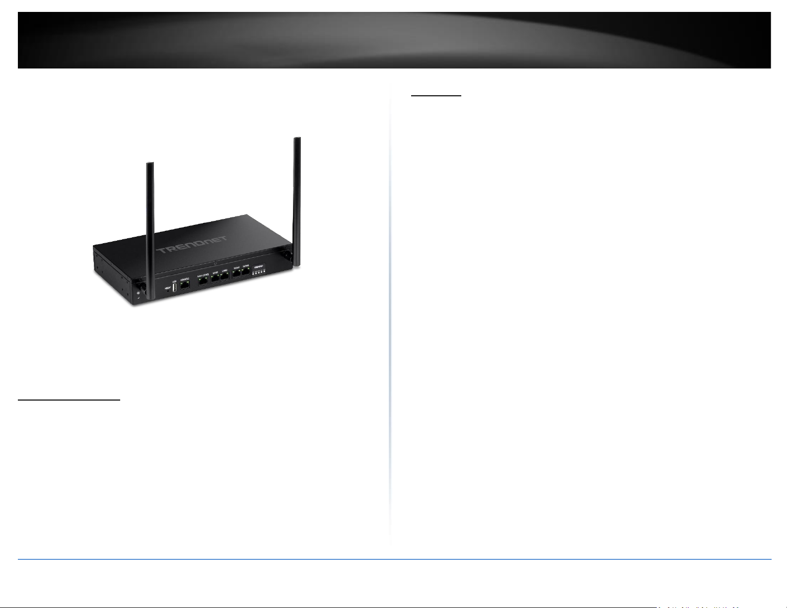
TEW-929DRU
Package Contents
In addition to your router, the package includes:
• Quick Installation Guide
• 2 x detachable high gain antennas
• Network cable (1.5 m/5 ft.)
• RJ-45 to RS-232 console cable (1.5m / 5 ft.)
• Power adapter (12V DC, 2 A)
• Rack mount kit
If any package contents are missing or damaged, please contact the retail store, online
retailer, or reseller/distributor from which the product was purchased.
Features
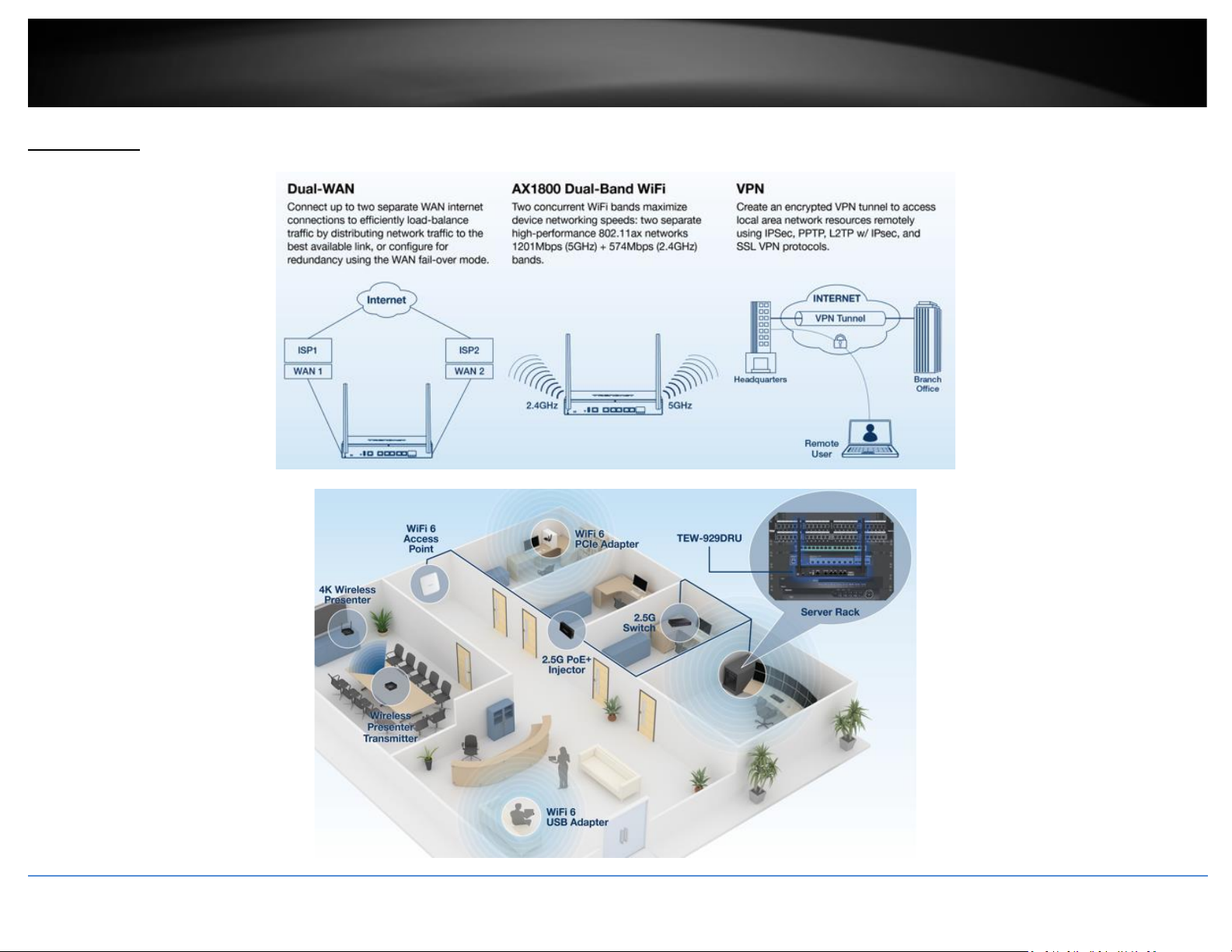
TRENDnet’s AX1800 Dual-Band Wireless Gigabit Dual-WAN VPN SMB Router, model
TEW-929DRU, features two concurrent WiFi bands to maximize device networking
speeds: two separate high performance 802.11ax networks (5GHz: 1201Mbps / 2.4GHz:
574Mbps). It features dual-WAN ports for load balancing or fail-over modes, and
encrypted Virtual Private Network (VPN) access for remote users. Dual-WAN ports
smooth network loading, minimize network downtime, and allow employees to access
your network from the Internet—all with a single router. This WiFi 6 router comes
equipped with a 2.5GBASE-T RJ-45 LAN port that provides higher gigabit speeds capable
of up to 2.5Gbps over your existing Cat5e or better cabling. Providing faster throughput
to your 2.5G compatible devices such as Network attached storage and high-speed WiFi
6 access points.
This wireless router features advanced management, QoS, VLAN, VPN, and other
capabilities to ensure optimal performance, scalability, and protection of your network.
Intelligently manage your offices’ web access with our advanced content filtering tool
powered by Bark®, increase employee productivity and finally take control of your
internet.
Dual-WAN
Supports up to two separate WAN internet connections for load-balancing or fail-over
modes
Ports
1x 2.5G LAN port, 2 x Gigabit LAN ports, 1 x RJ-45 console port, 1 x USB 2.0 share port
Dual-Band WiFi 6
Two concurrent WiFi bands maximize device networking speeds: two separate high
performance 802.11ax networks 1201Mbps (5GHz) + 574Mbps (2.4GHz) bands
2.5G Support
Features a 2.5GBASE-T RJ-45 LAN port that delivers higher gigabit speeds capable of up
to 2.5Gbps over your existing Cat5e or better cabling. Providing faster throughput to
your 2.5G compatible devices such as Network attached storage and high-speed WiFi 6
access points.
Page 5

© Copyright 2023 TRENDnet. All Rights Reserved.
TRENDnet User’s Guide
TEW-829DRU
2
Pre-Encrypted Wireless
For your convenience the router’s WiFi bands are pre-encrypted with their own unique
WPA3 passwords
VPN
Supports IPsec, PPTP, L2TP w/ IPsec, and SSL VPN protocols for encrypted remote access
to local area network (LAN) resources over the internet
Inter-VLAN Routing
Provides routing capabilities between VLANs
QoS
Intelligently prioritize voice, video, and other data traffic to improve network efficiency
and overall performance
Rack Mount Design
Sturdy metal housing with rack mount brackets included
Wall Mountable
Wall mount ready
Online Firmware Updates
Automatic notification of firmware updates
Management
Supports web browser (HTTP, HTTPS), CLI, SSH and Telnet management
Page 6
© Copyright 2023 TRENDnet. All Rights Reserved.
TRENDnet User’s Guide
TEW-829DRU
3
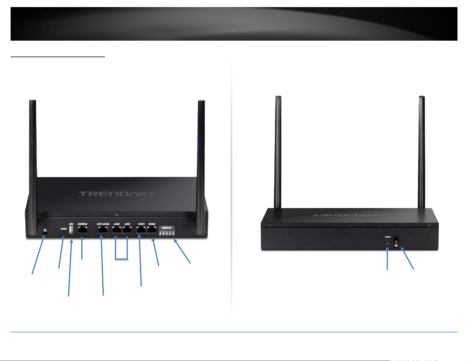
Product Hardware Features
Front Panel View
Rear Panel View
On(-)/Off(o)
Power Switch
Power
Port
LED
Indicators
WAN2
Port
WAN1
Port
Gigabit
LAN Ports
2-3
2.5Gbps Lan
Port 1
RJ-45
Console
Port
USB 2.0
Port
Reset
Button
Security
Slot
Page 7
© Copyright 2023 TRENDnet. All Rights Reserved.
TRENDnet User’s Guide
TEW-829DRU
4
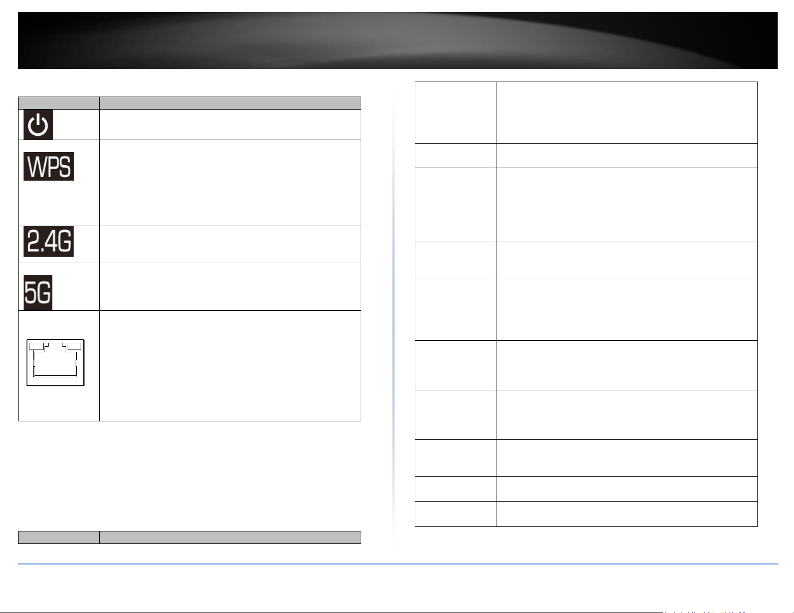
LED Indicators
LED
Description
Solid Blue – Device is receiving power and turned on.
Off – Device is not receiving power or turned off.
Solid Blue – WPS connection process was successful. WPS
LED will remain on after successful connection for 2 minutes.
Blinking Blue – WPS is activated and setup process has
started. Within 2 minutes, start the WPS process on your
WPS client device to connect.
Off – WPS setup process has stopped or has not been
activated.
Solid Blue – 2.4GHz (2-stream) wireless radio is turned on.
Blinking Blue – Data transmission on 2.4GHz radio.
Off – 2.4GHz (2-stream) wireless radio turned off.
Solid Blue – 5GHz1 (2-stream) wireless radio is turned on.
Blinking Blue – Data transmission on 5GHz1 radio.
Off – 5GHz1 (2-stream) wireless radio turned off.
Port LEDs
LAN 1-3, WAN1 & WAN2 Ports
LED (Left Side)
Solid Green – Port is connected at 1Gbps or 2.5Gbps link
speed.
Off – Port is connected at 10Mbps or 100Mbps link speed.
LED (Right Side)
Blinking Green - Data activity/transmission on port.
Port/Button Description
Ports/Buttons
Description
Grounding Point
Allows the device chassis to be connected to a known ground
point for electrical safety and protection possible shock or
surge during device operation and handling. (Grounding wire
and screw not included.)
Security Slot
Allows for an optional cable lock attachment to secure the
device to a physical location.
RJ-45 Console
Port
Using the included RJ-45 to RS-232 console cable, this
interface provides console/terminal (command line interface)
access to the device for management and troubleshooting
purposes.
Terminal Settings:
Baud: 115200 / Data: 8 / Stop: 1 / Parity: None / Flow: None
USB 3.0 Port
Allows for an optional USB storage device (flash drive,
external HDD, etc.) to be connected and used as a network
share through the Samba protocol. (FAT32/NTFS format only)
LAN Interface
Ports 1-3
Connect network devices to the LAN interface ports 1-3 at
2.5Gbps (Port 1 only), Gigabit, 10Mbps/100Mbps Full/Half
Duplex. By default, management access to the GUI and
command line interface via default LAN IP address:
192.168.10.1 / 255.255.255.0
WAN1 Interface
Port
Connects to your Internet Service Provider (ISP) equipment
for Internet connectivity such as modem. By default, WAN
mode is set for failover and WAN1 is configured as the
primary WAN link for Internet connectivity.
WAN2 Interface
Port
Connects to your Internet Service Provider (ISP) equipment
for Internet connectivity such as modem. By default, WAN
mode is set for failover and WAN2 is configured as the
secondary WAN link for Internet connectivity.
Reset Button
Resets device to factory defaults. Using a paperclip, push and
hold the reset button for 15 seconds and release to reset the
device to factory defaults.
Power Port
Connects the included power adapter to supply device
power.
On(-)/Off(o)
Power Switch
Turns the device power On(-) or Off(o).
Page 8
© Copyright 2019 TRENDnet. All Rights Reserved.
TRENDnet User’s Guide
TEW-829DRU
5
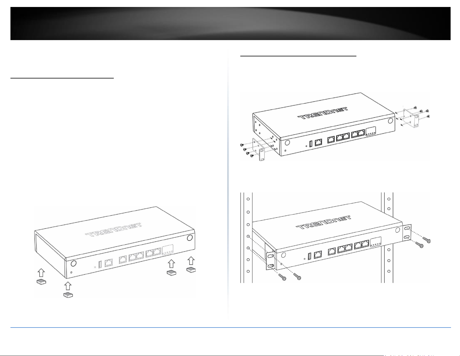
Applications
Page 9
© Copyright 2019 TRENDnet. All Rights Reserved.
TRENDnet User’s Guide
TEW-829DRU
1
Router Installation
Desktop Hardware Installation
The site where you install the hub stack may greatly affect its performance. When
installing, consider the following pointers:
Note: The router model may be different than the one shown in the example
illustrations.
• Install the Router in a fairly cool and dry place.
• Install the Router in a site free from strong electromagnetic field generators (such
as motors), vibration, dust, and direct exposure to sunlight.
• Leave at least 10cm of space at the front and rear of the hub for ventilation.
• Install the Router on a sturdy, level surface that can support its weight, or in an
EIA standard-size equipment rack. For information on rack installation, see the
next section, Rack Mounting.
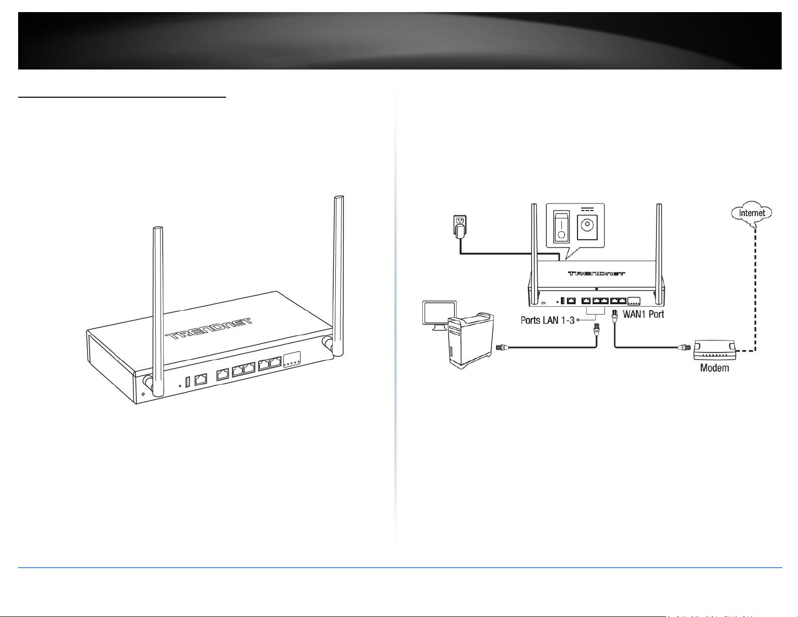
• When installing the Router on a level surface, attach the rubber feet to the
bottom of each device. The rubber feet cushion the hub and protect the hub
case from scratching.
Rack Mount Hardware Installation
The router can be mounted in an EIA standard-size, 19-inch rack, which can be placed in
a wiring closet with other equipment. Attach the mounting brackets at the router’s
front panel (one on each side), and secure them with the provided screws.
Then, use screws provided with the equipment rack to mount each router in the rack.
Note: The look of the router may be different than what is actually displayed.
Page 10
© Copyright 2019 TRENDnet. All Rights Reserved.
TRENDnet User’s Guide
TEW-829DRU
2
Basic Installation and Configuration
Note: It is recommended that you configured the wireless router from a wired computer.
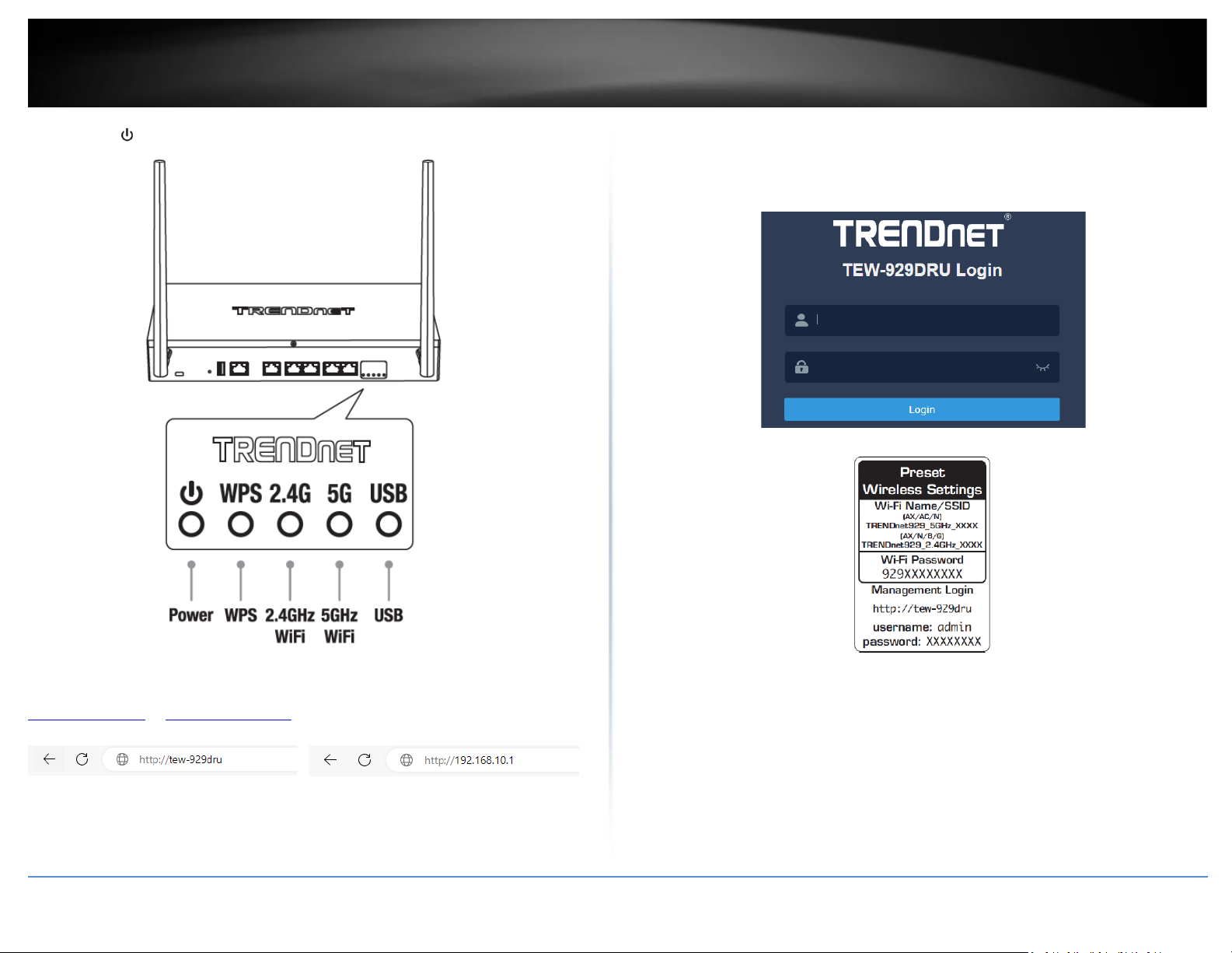
1. Attach the antennas to the front and back of the router and position them for the
best WiFi coverage. It is recommended that you position all antennas vertically as
shown for initial installation and adjust as needed later on.
2. Connect a network cable from the WAN1 port of your router to your modem.
3. Connect a network cable from one of the LAN ports (1-3) of your router to your
computer.
4. Connect the includes power adapter from a power outlet to your router power port
and push the Power On(-)/Off(o) switch into the On(-) position.
Page 11
© Copyright 2019 TRENDnet. All Rights Reserved.
TRENDnet User’s Guide
TEW-829DRU
3
5. The Power ( ), 2.4G, 5G LEDs will turn on solid indicating that the router is ready.
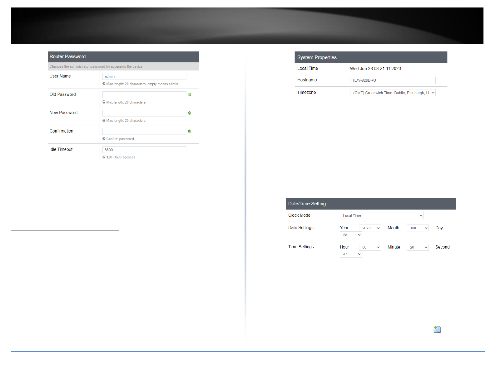
6. Open your web browser on the connected computer and in the address bar, enter
http://tew-929dru or http://192.168.10.1 and press Enter to access the router web
configuration page.
7. Enter the default User Name and Password, then click Login. By default, the preconfigured user name and password are located on the included preset wireless settings
sticker or device label located on the bottom of the router.
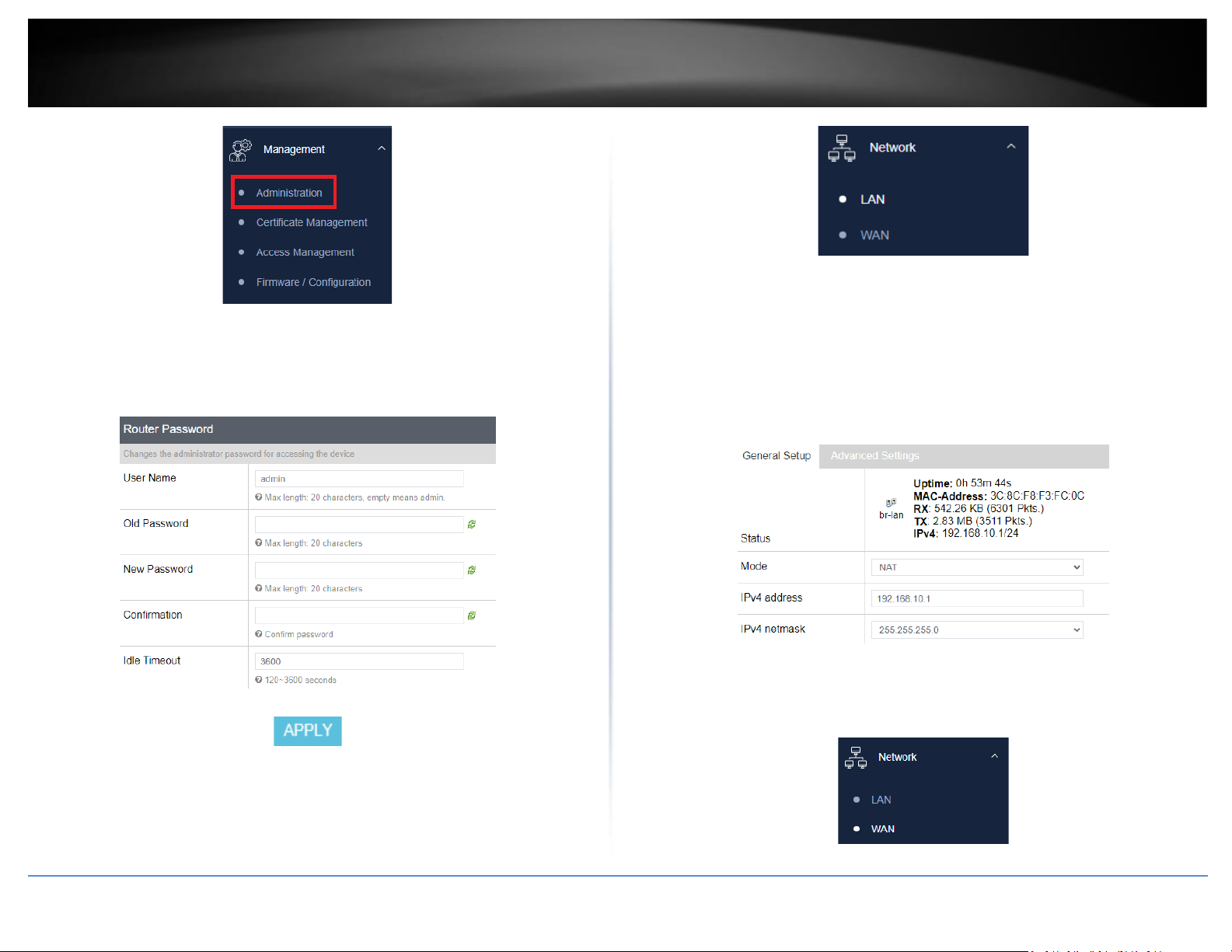
8. To change the administrator password for the router configuration, click
Management and click Administration.
Note: By default, the administrator password has been pre-configured for your
convenience and can be located on the included wireless settings sticker or on the device
label located on the bottom of the router. If you are modifying the administrator
password, you will need to log into the router configuration using the new password.
Page 12
© Copyright 2019 TRENDnet. All Rights Reserved.
TRENDnet User’s Guide
TEW-829DRU
4
9. Enter the new administrator username/password in the User Name, Old Password,
New Password field and re-type the new password in the Confirmation field. Click
Apply to save and commit the changes.
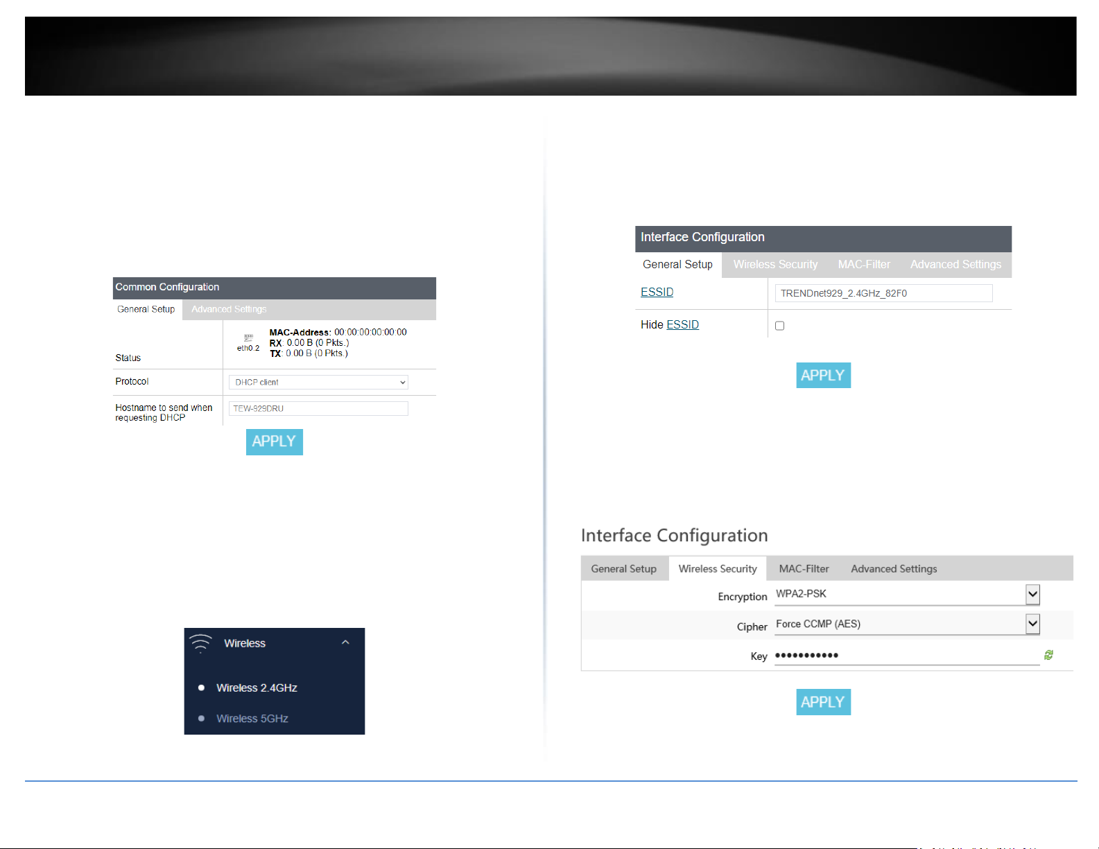
10. To change your router’s LAN IPv4 address settings, click on Network and click LAN.
11. Under Common Configuration and General Setup, enter the new LAN IPv4 address
and subnet mas in the IPv4 address and IPv4 netmask fields. Click Apply to save and
commit the changes. Please wait for the new address settings to be applied and log back
into the router web configuration page using the new LAN IPv4 address.
Note: If your computer IP address settings are not automatically updated to the new
settings, you may need to manually renew your computer IP address settings in order
for your to log back into the router web configuration with the new LAN IPv4 address
settings.
12. To configure your WAN1 Internet connection settings, click Network, click WAN, and
click WAN1.
Page 13
© Copyright 2019 TRENDnet. All Rights Reserved.
TRENDnet User’s Guide
TEW-829DRU
5
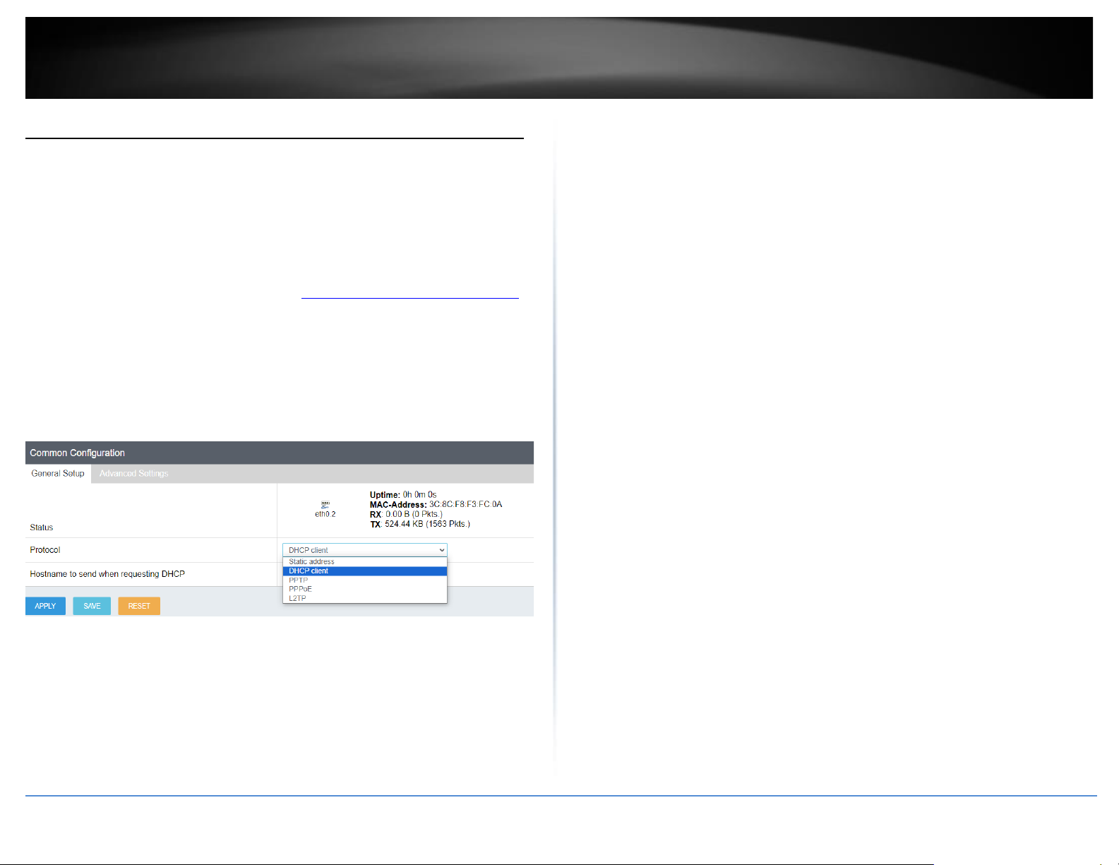
13. Under Common Configuration and General Setup, click the Protocol drop-down list
and select the appropriate protocol (Static address, DHCP client, PPTP, PPPoE, L2TP) for
your Internet connection. DHCP client is the typical protocol in which the connection
settings are automatically obtained by your ISP (Internet Service Provider). If you are
unsure about the Internet connection settings, please contact your ISP for details. After
you have completed the Internet connection settings, click Apply to save and commit
the changes.
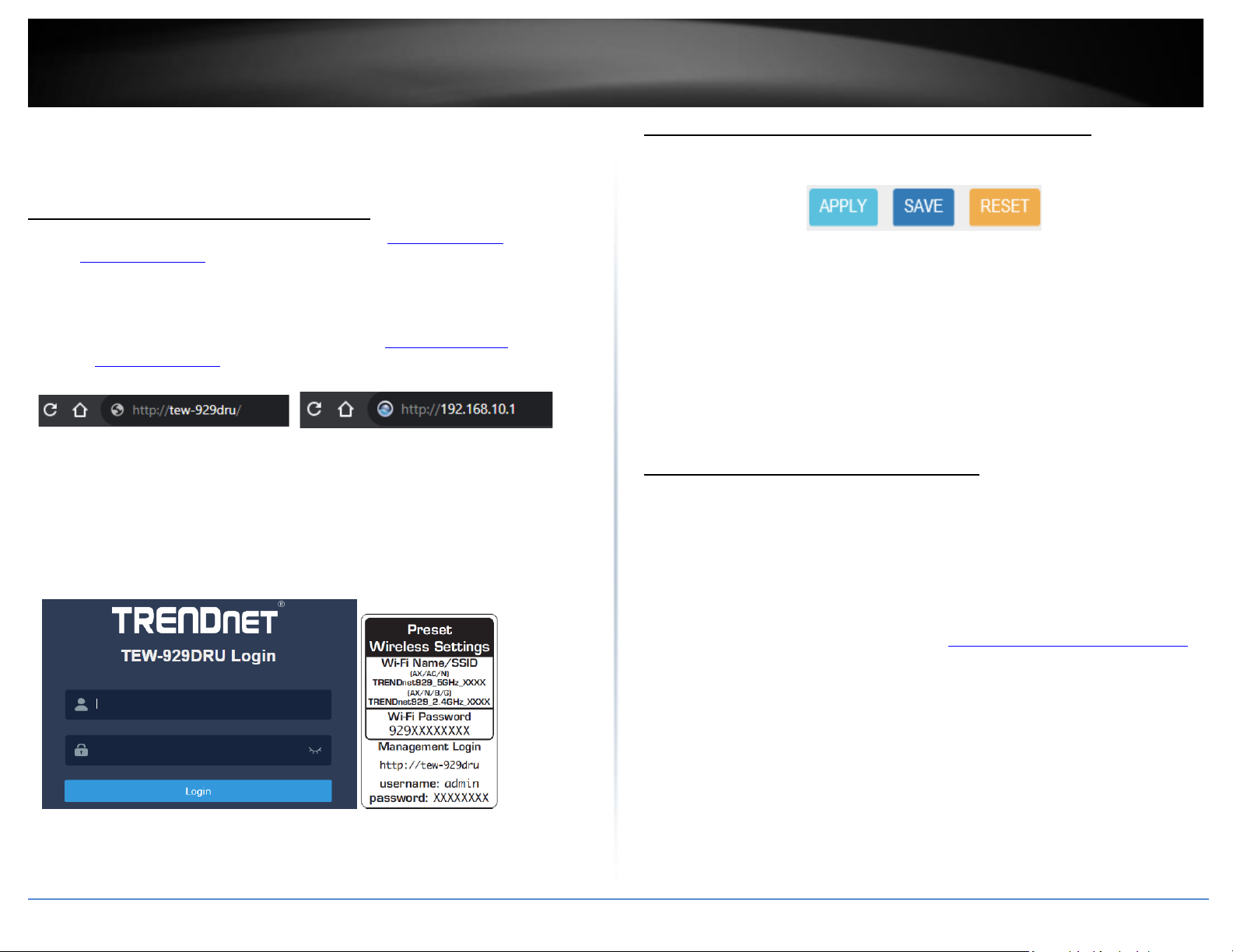
14. To configure your wireless network name/SSID and wireless encryption settings,
click Network and click the wireless band you would like to configure. Wireless 2.4GHz,
or Wireless 5GHz.
Note: By default, the wireless network name/SSID has been pre-configured for your
convenience and can be located on the included wireless settings sticker or on the device
label located on the bottom of the router. If you are modifying the wireless settings, you
will need to connect to the router with your WiFi clients using the new settings.
15. To change the wireless network name/SSID for the selected wireless band, under
Interface Configuration and General Setup, enter the new name in the ESSID field and
click Apply to save and commit the changes.
Note: The wireless network name/SSID is the name your WiFi clients will need to search
and discover when connecting to your router wireless network.
16. To change the wireless encryption key for the selected wireless band, under
Interface Configuration Wireless Security, enter the new encryption in the Key field and
click Apply to save and commit the changes.
Note: WPA2-PSK AES wireless encryption is strongly recommended. The wireless
encryption key is the key your WiFi clients will need to enter when connecting to your
router wireless network.
Page 14
© Copyright 2019 TRENDnet. All Rights Reserved.
TRENDnet User’s Guide
TEW-829DRU
6
Basic Router Settings
Access your router management page
Note: Your router management page URL/domain name http://tew-929dru or IP
address http://192.168.10.1 is accessed through the use of your Internet web browser
(e.g. Internet Explorer®, Firefox®, Chrome™, Safari®, Opera™) and will be referenced
frequently in this User’s Guide.
1. Open your web browser and go to URL/domain name http://tew-929dru/ or IP
address http://192.168.10.1. Your router will prompt you for a user name and
password.
2. For added security, the router is pre-configured with a unique administrator
password. You can find the Password on the sticker included in the router package
contents or on the device label located on the bottom of the router. Enter your
Username and Password, then click LOGIN.
• User Name: admin
• Password: (xxxxxxxx)
Note: User Name and Password are case sensitive.
Saving and applying router configuration changes
In the router management page, pages may include all, some, or one of the options
below. Some configuration changes may require a device reboot.
• Reset – Clicking this option will reset all settings to their previous configuration
on a specific page.
• Apply – Clicking this option will save and apply the configuration changes on a
specific page which will take effect immediately.
• Save – Clicking this option will temporarily save the changes and allow you to
temporarily save multiple configuration changes and apply all configuration
changes at the same time. When you are ready to save and apply the
configuration changes permanently, click on the notification in the top right
corner.
Change your administrator password
Administrator > Administration
By default, the administrator password has been pre-configured a unique password for
your convenience. You can find the pre-configured administrator password on the
wireless sticker included in your router package contents or also located on the router
device label located on the bottom of the device. This section will allow you to change
the default administrator password used to log into your router management page.
1. Log into your router management page (see “Access your router management page”
on page 6).
2. Click on Management and click on Administration.
3. Enter the new administrator username/password in the User Name, Old Password,
New Password field and re-type the new password in the Confirmation field. Click
Apply to save and commit the changes.
Note: The idle timeout setting is used to define the period of inactivity in the router
management page before automatically logging out.
Page 15
© Copyright 2023 TRENDnet. All Rights Reserved.
7
TRENDnet User’s Guide
TEW-929DRU
Note: If you change the administrator password, you will need to access the router
management page using the User Name “admin” and the new password instead of the
pre-configured default password. If you reset the device to factory defaults, you will
need to access the router management page using the pre-configured settings on the
included wireless sticker in the router package contents or on device label located on the
bottom of the router.
Set your router date and time
System > Time/Date
It is recommended to set the router date and time for scheduling functions and logging
functions for monitoring and troubleshooting.
1. Log into your router management page (see “Access your router management page”
on page 6).
2. Click on System and click on Time/Date.
3. Review the settings below. Click Apply to save and commit the changes.
System Properties
• Local Time – Displays the current day, date, and time. Clicking the SYNC WITH
BROWSER button will automatically copy the current day, date, and time
settings from the web browser and allows the time to be set manually.
• Hostname – Modifies the router host name. The host name identifies is the
name used to identify the router to other computer or devices on the network.
Modifying this setting will modify the hostname used when accessing the
router management page using the hostname or when using the Samba USB
share feature.
• Timezone – Click the drop-down list to select the appropriate time zone.
Time Synchronization
• Clock Mode – Select the method of clock mode
o Local Time: Manually input the time
o NTP: Time is grabbed by a designated NTP server
▪ NTP server candidates – Enter the domain name of the
network time server to obtain time and settings. (e.g.
pool.ntp.org)
o Cloud Sync Time: The time will be synched with TRENDnet Hive cloud
server (optional license is required)
Note: You can add multiple time servers by clicking . If one server
is not available, your router will try the next available server in the list.
Page 16
© Copyright 2023 TRENDnet. All Rights Reserved.
8
TRENDnet User’s Guide
TEW-929DRU
Create time schedules
System > Schedule
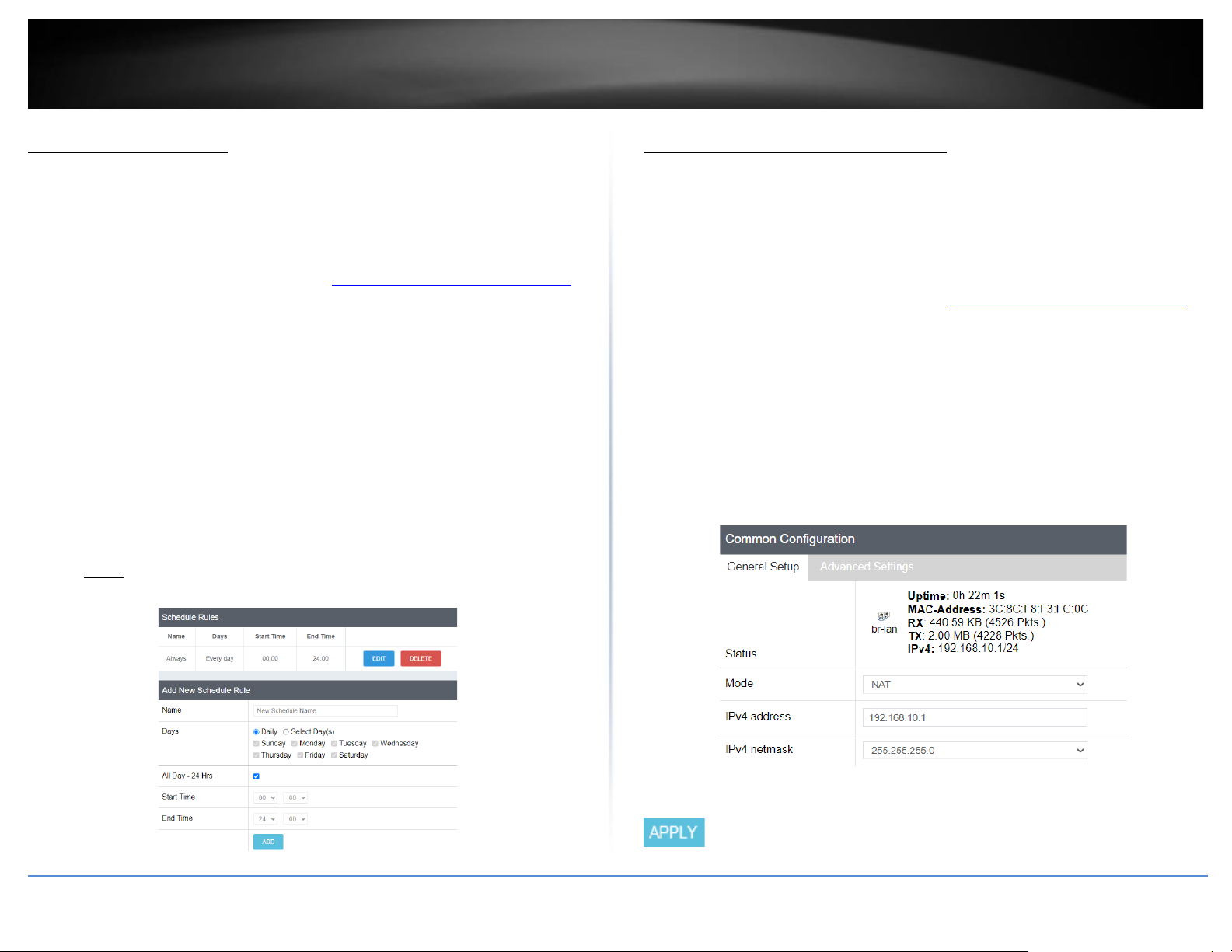
Your router allows you to create schedules to specify a time period when a feature
should be activated and deactivated. Before you use the scheduling feature on your
router, ensure that your router system time and date settings are configured correctly.
1. Log into your router management page (see “Access your router management page”
on page 6).
2. Click on System and click Schedule.
3. Review the settings below. Click Add to add the new schedule to the list and Apply to
save and commit the changes.
• Name – Enter a name for the new schedule rule.
• Days – Choosing Daily will set the set the schedule rule to occur at the specified
time every day. Choosing Select Day(s) will allow to manually select which
specific days for the schedule.
• All Day – 24 Hrs – Checking this option will set the schedule to run all 24 hours
instead of manually configured a specified time period.
• Start Time / End Time – Manually define a time period for the schedule.
Note: The time period is specified in 24 hour format.
Change LAN IPv4 address settings
Network > LAN
Note: The default LAN interface IPv4 address settings is 192.168.10.1 / 255.255.255.0
and also assigned to LAN ports 1-8 by default. If the LAN IPv4 address settings are
modified, you will need to log into the router management page with the new IPv4
address settings.
1. Log into your router management page (see “Access your router management page”
on page 6).
2. Click on Network and click LAN.
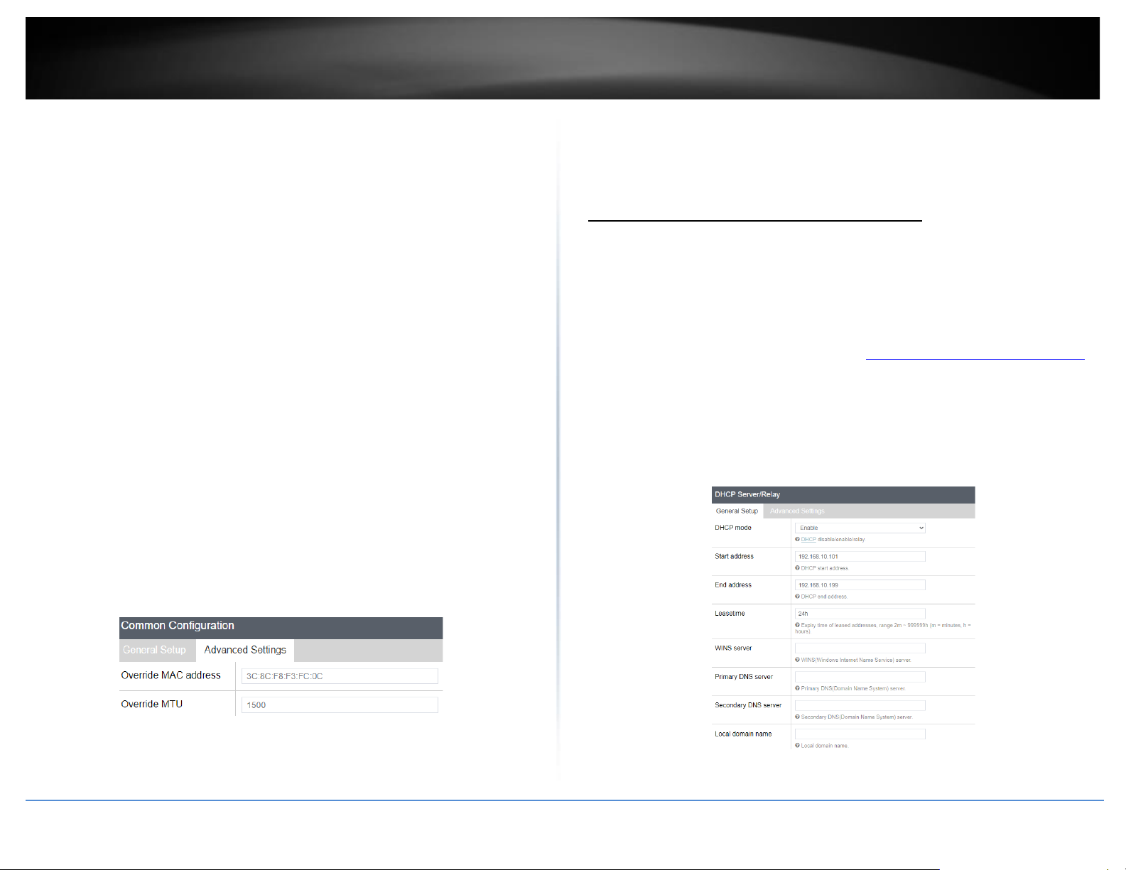
3. Under the Common Configuration section, you can enter the new LAN interface IP
address settings.
• IPv4 address – Enter the new LAN IPv4 address. (e.g. 192.168.50.1)
• IPv4 netmask – Select or Enter the new LAN IPv4 subnet mask. The drop-down
menu will list class A, B, C, or custom which will allow you to manually enter a
custom subnet mask. (e.g. 255.255.255.0)
4. Click Apply to
Page 17
© Copyright 2023 TRENDnet. All Rights Reserved.
9
TRENDnet User’s Guide
TEW-929DRU
Below is a reference of the additional LAN settings if you choose to make other
configuration changes to these sections.
General Setup
• Status – LAN Interface (br-lan)
o Uptime – Displays the amount time the LAN interface has been up and
continuously running. This time will reset if the router is powered off
or router is rebooted.
o MAC-Address – Displays the current MAC address assigned to the LAN
interface.
o Rx – Displays the total amount of data received by the LAN interface in
MB (# of packets) since the start of the currently displayed uptime.
o Tx – Displays the total amount of data transmitted by the LAN
interface in MB (# of packets) since the start of the currently displayed
uptime.
o IPv4: Displays the current IPv4 address settings assigned to the LAN
interface.
• Mode – Allows you to change the function between NAT mode or Route Only
(NAT-less).
o NAT – The default router mode which uses network address
translation between the local internal (LAN/VLAN) interfaces and
external (WAN1/WAN2) interfaces translating public and private IP
addressing.
o Route Only (NAT-less) – This mode disables the NAT function between
internal and external interfaces and may also be known as classical
routing mode. This mode should only be used when the router is using
for local internal IP routing only
Advanced Settings
• Override MAC Address – This parameter allows you to assign a new LAN
interface (br-lan) MAC address. Typically, this parameter does not need to be
modified. (e.g. AA:BB:CC:DD:EE:FF)
• Override MTU – The default MTU (maximum transfer unit) or frame size is set
to 1500 bytes. This parameter allows you to assign a new MTU size. Typically,
this parameter does not need to be modified.
Configure LAN IPv4 DHCP server settings
Network > LAN
Note: The internal DHCP server function is enabled by default on the LAN interface to
automatically distribute IP address settings to network devices connected to the LAN and
wireless LAN interfaces. The internal DHCP server only supports only class C IP address
range. The default IP range is 101 – 199 (192.168.10.101 – 192.168.10.199)
1. Log into your router management page (see “Access your router management page”
on page 6).
2. Click on Network and click LAN.
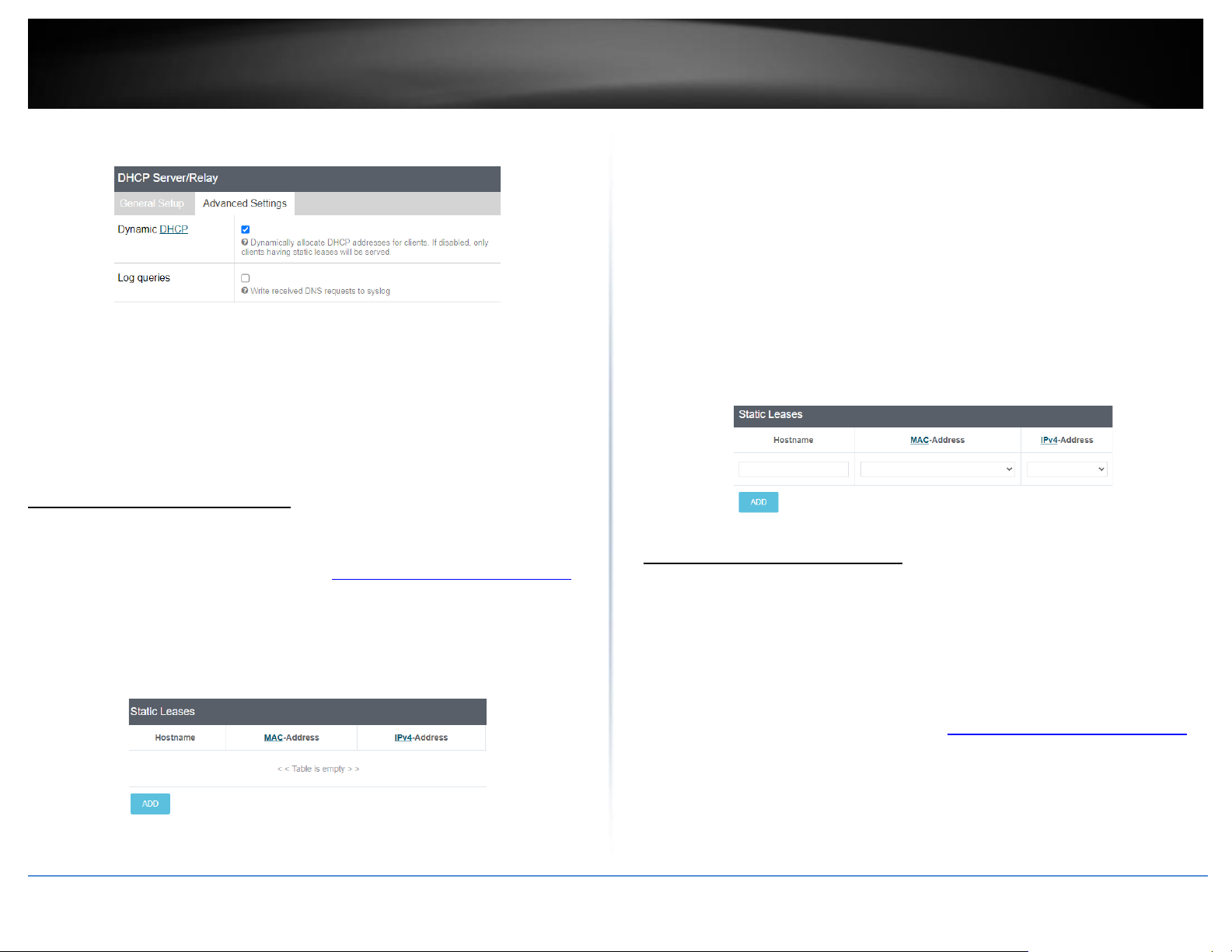
3. Under the DHCP Server/Relay section, you can modify or enter the new DHCP settings
and click Apply to save and commit the changes.
Page 18

© Copyright 2023 TRENDnet. All Rights Reserved.
10
TRENDnet User’s Guide
TEW-929DRU
• DHCP mode – Allows you to set the mode to Enable, Disable, or Relay.
o Enable – Using this setting enables the DHCP server function the LAN
interface.
o Disable - Using this setting disabled the DHCP server function on the
LAN interface.
o Relay – Using this setting allows you to use an external DHCP server
instead of your router’s internal DHCP server to distribute IP address
settings on the LAN interface. If choosing this setting, enter the IP
address of your external DHCP relay server.
• Start address – Enter the starting value of DHCP IPv4 address range. (e.g. If
your LAN IPv4 address is 192.168.50.1, entering 120 will define the first IP
address of the DHCP pool is 192.168.50.120)
• End address – Enter the ending value of DHCP IPv4 address range. (e.g. If your
LAN IPv4 address is 192.168.50.1, entering 200 will define the last IP address of
the DHCP pool is 192.168.50.200)
• Leasetime – Enter the lease time in hours (h) or minutes (m) DHCP clients will
hold their IP address settings before automatically requesting a new lease (IP
address settings) from the internal DHCP server. (e.g. To specify 24 hours, enter
24h. To specify 480 minutes, enter 480m.)
• WINS server – Enter the IPv4 address of your WINS (Windows Internet Name
Server) for internal host name resolution on your local network to be
distributed to DHCP clients. The WINS server provides host name to IP address
resolution for the NetBIOS naming service. This parameter is optional. (e.g.
192.168.50.250)
• Primary DNS – Enter the IPv4 address of your primary DNS (Domain Name
System) server for Internet domain name resolution to be distributed to DHCP
clients. By default, the internal DHCP server uses DNS relay and provides the
router LAN IPv4 address as the primary DNS server to DHCP clients. The DNS
server provides Internet domain name to IP address resolution when
computers are accessing or browsing Internet websites. This parameter is
optional. (e.g. If entering 8.8.8.8, this DNS server will be provided DHCP clients
instead of the router’s LAN IPv4 address to resolve Internet domain names such
as trendnet.com )
• Secondary DNS – Enter the IPv4 address of your secondary DNS (Domain Name
System) server for Internet domain name resolution to be distributed to DHCP
clients. If the primary DNS server cannot be reached, the secondary DNS server
will be used. This parameter is optional. (e.g. 8.8.4.4)
• Local domain name – Enter a domain name to distribute to DHCP clients. This
parameter is optional. (e.g. trendnet.com)
Below is a reference of the additional DHCP Server/Relay settings if you choose to make
other configuration changes to these sections.
Page 19
© Copyright 2023 TRENDnet. All Rights Reserved.
11
TRENDnet User’s Guide
TEW-929DRU
Advanced Settings
• Dynamic DHCP – Checking this option the enables the DHCP server to
distribute IPv4 address settings dynamically to clients. If this option is
unchecked, IPv4 address settings will only be assigned to DHCP clients with a
static DHCP reservation. Typically, this parameter does not need to be
modified.
• Log Queries – Checking this option will enable generate logging to internal or
syslog of any DNS queries. Typically, this parameter does not need to be
modified.
Add static DHCP reservations
Network > LAN
1. Log into your router management page (see “Access your router management page”
on page 6).
2. Click on Network and click LAN.
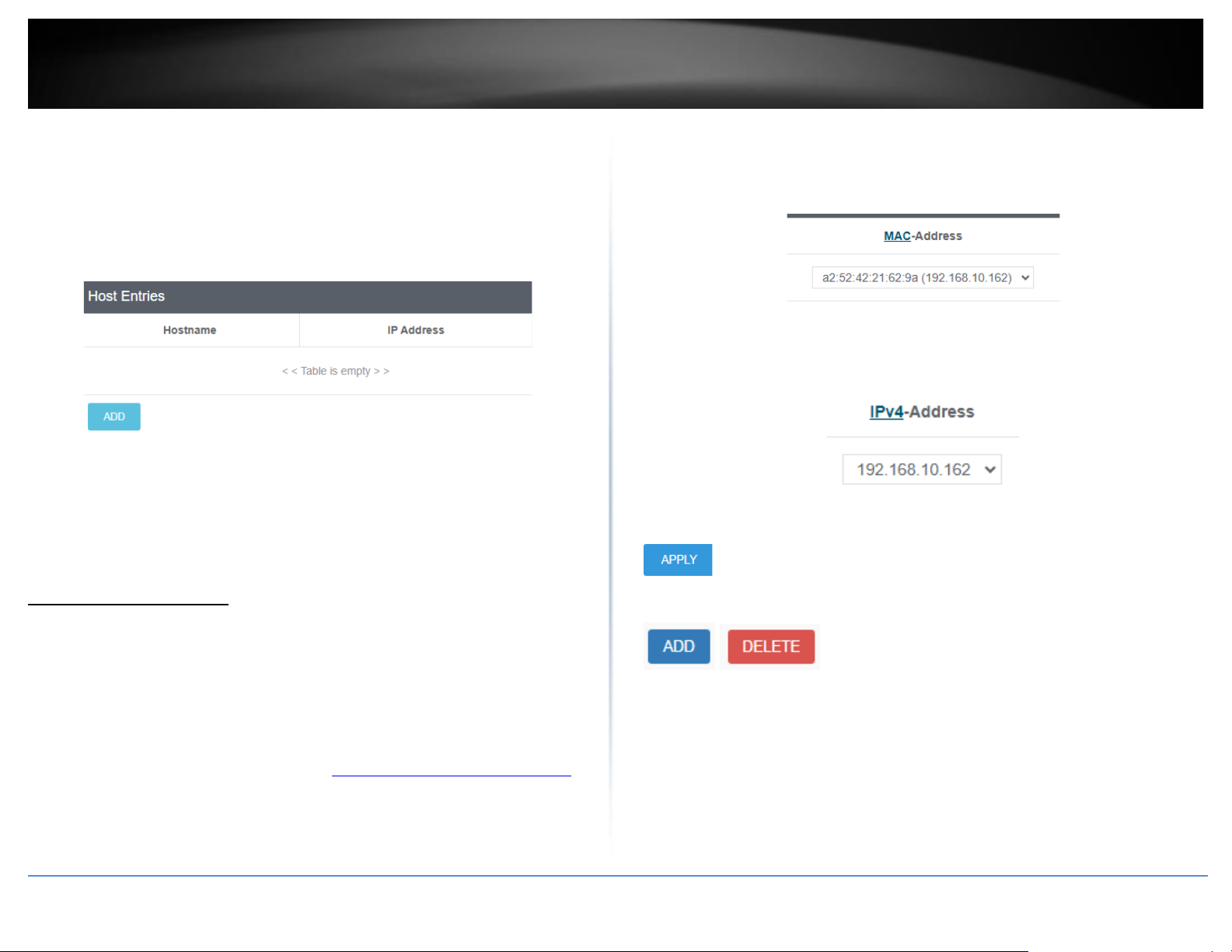
3. Under the Static Leases section, click Add.
4. Enter the parameters for the static DHCP reservation and click Apply to save and
commit the changes.
Note: The network device or computer the reservation is created will need to release and
renew the IPv4 address settings in order to obtain the new IP address settings.
• Hostname – Enter a name for the DHCP reservation. (e.g. trendnetpc)
• MAC-Address – Enter the MAC (Media Access Control) address of the
computer or network device to assign to the reservation. You can also click the
drop-down list to select from a list of network devices detected by the router
that have been assigned IPv4 address settings through DHCP. (e.g.
AA:BB:CC:DD:EE:FF)
• IPv4-Address – Enter the IPv4 address to assign to the computer or network
device for the reservation. You can also click the drop-down list to select from
list o of network devices detected by the router through DHCP. (e.g.
192.168.50.150)
Add static host name entries
Network > LAN
The router can be used for host name to IP address resolution of computers or network
devices on your local network similar to a WINS server however, entries will not
dynamically populate and each entry must be manually entered. For clients to resolve
the manually entered static entries, DHCP clients must use the router LAN IPv4 address
as the WINS server.
1. Log into your router management page (see “Access your router management page”
on page 6).
2. Click on Network and click LAN.
3. Under the Host Entries section, click Add.
Page 20
© Copyright 2023 TRENDnet. All Rights Reserved.
12
TRENDnet User’s Guide
TEW-929DRU
4. Enter the parameters for the static host name entry and click Apply to save and
commit the changes.
• Hostname – Enter the host name. (e.g. trendnetpc)
• IP Address – Enter the IPv4 address to resolve to host name. (e.g.
192.168.50.150)
Add static ARP entries
Network > LAN
ARP (Address Resolution Protocol) is the protocol responsible for resolve IP addresses to
hardware MAC addresses. Typically, ARP entries are dynamically learned and refreshed
in the ARP table however, in the case where your application requires static ARP entries
to always be present in the router ARP table, you can manually enter and add them to
the router. (ex. applications: WoL (Wake on LAN) or Wake on WAN)
1. Log into your router management page (see “Access your router management page”
on page 6).
2. Click on Network and click LAN.
3. Under the Static ARP section, click the MAC-Address drop-down list to select a MAC
address from the list or select customer to manually enter a MAC address (format
example: aa:bb:cc:dd:ee:ff).
4. Click the IPv4-Address drop-down list and select the IPv4 address to assign to the
MAC address ARP table entry or select custom to manually enter an IPv4 address
(format example: 192.168.10.129)
5. Click Apply to save and commit the changes.
Note: You can specify additional static ARP entries by clicking Add. Delete existing
entries by clicking the Delete button next to the entry to be removed.
Page 21
© Copyright 2023 TRENDnet. All Rights Reserved.
13
TRENDnet User’s Guide
TEW-929DRU
Configure WAN1 / WAN2 interfaces for Internet connectivity
Network > WAN1/WAN2
By default, the WAN configuration is set to use WAN1 as the primary connection for
Internet connectivity and failover to WAN2 secondary if there is fault in connectivity to
WAN1. This section will explain how to set up the WAN1 or WAN2 interfaces for
Internet connectivity to your ISP (Internet Service Provider).
1. Log into your router management page (see “Access your router management page”
on page 6).
2. Click on Network and click WAN. Click WAN1 or WAN2 to configure the selected
WAN.
3. Under the Common Configuration section, click the Protocol drop-down list and
select the Internet connection provided by your ISP.
4. Complete all of the fields required by your ISP and click Apply to save and commit the
changes.
Below is a reference of the additional WAN settings if you choose to make other
configuration changes to these sections.
General Setup
• Status – LAN Interface (br-lan)
o Uptime – Displays the amount time the WAN1/WAN2 interface has
been up and continuously running. This time will reset if the router is
powered off or router is rebooted.
o MAC-Address – Displays the current MAC address assigned to the
WAN1/WAN2 interface.
o Rx – Displays the total amount of data received by the WAN1/WAN2
interface in MB (# of packets) since the start of the currently displayed
uptime.
o Tx – Displays the total amount of data transmitted by the
WAN1/WAN2 interface in MB (# of packets) since the start of the
currently displayed uptime.
o IPv4: Displays the current IPv4 address settings assigned to the
WAN1/WAN2 interface.
• Dual WAN priority – Displays the current priority assignment for the selected
WAN interface. The WAN priority settings can be configured under Network >
Multiple WAN. By default, the WAN configuration is set to use WAN1 as the
primary connection for Internet connectivity and failover to WAN2 secondary if
there is fault in connectivity to WAN1.
• Hostname to send when requesting DHCP – If your ISP requires to send
specific hostname with the DHCP request for Internet connectivity, enter the
required host name in the field. Applies to DHCP client/PPTP/L2TP WAN
protocols.
• WAN mode – Applies to PPTP/L2TP WAN protocols.
o DHCP client – Using this option will set the WAN to obtain IP address
settings automatically from your ISP for Internet connectivity.
o Static IP – Using this option will require you to manually enter the
WAN IP settings required by your ISP for Internet connectivity.
• Connect mode – Applies to PPPoE/PPTP/L2TP WAN protocols.
o Keep alive – This option will keep the connection on at all times.
o On demand – This option will automatically disconnect after the max.
idle time is reached and will automatically re-establish connection
when Internet access is used.
• Access concentrator / Service name – Optional parameters required only if ISP
requires for Internet connectivity. Applies to PPPoE WAN protocol.
• MPPE support– Optional parameter (applies Microsoft Point-to-Point
Encryption) required only if ISP requires for Internet connectivity. Applies to
PPTP WAN protocol.
Page 22
© Copyright 2023 TRENDnet. All Rights Reserved.
14
TRENDnet User’s Guide
TEW-929DRU
• Use DNS servers advertised by peer- If checked, automatically obtains DNS
service IP address settings from your ISP. If unchecked, allows you to specify
custom DNS server IP addresses. Applies to PPPoE/PPTP/L2TP WAN protocols.
Advanced Settings
• Bring up on boot – The parameter is enabled to bring the WAN1/WAN2
interface up during device boot. Typically, this parameter does not need to be
modified.
• Use builtin IPv6-management – Enables/disables IPv6 protocol on the
WAN1/WAN2 interface. Typically, this parameter does not need to be
modified.
• Enable IPv6 negotiation on PPP link – Enables/disables IPv6 when using the
PPPoE/L2TP WAN protocols. Typically, this parameter does not need to be
modified.
• Use broadcast flag – Optional parameter if your ISP may requires that DHCP
requests from your device be sent as broadcasts or unicasts for IP address
settings for Internet access.
• Use default gateway – This parameter automatically created a default gateway
route in the device routing table to access the Internet through the selected
WAN interface. If unchecked, the default gateway route for Internet access
must be entered in manually in the device routing table settings. Typically, this
parameter does not need to be modified.
• Use gateway metric – This parameter is the route priority value assigned to the
default gateway route. Range: 0-9999, 0 being the highest priority. Typically,
this parameter does not need to be modified.
• Use DNS servers advertised by peer- If checked, automatically obtains DNS
service IP address settings from your ISP. If unchecked, allows you to specify
custom DNS server IP addresses. Applies to the DHCP client WAN protocol.
• Client ID to send when requesting DHCP – Optional parameter only required if
your ISP requires a specific client ID to be sent when requesting IP address
settings for Internet access. Applies to DHCP client WAN protocol.
• Vendor Class to send when requesting DHCP – Optional parameter only
required if your ISP requires a specific vendor class to be sent when requesting
IP address settings for Internet access. Applies to DHCP client WAN protocol.
• Override MAC address – Optional parameter used to change the WAN
interface MAC address if you are experiencing issues obtaining IP address
settings from your ISP. This parameter is more commonly known as MAC
address cloning where you can assign a LAN computer MAC address to the
WAN interface. Applied to DHCP client WAN protocol.
• Override MTU – The default MTU (maximum transfer unit) or frame size is set
to 1500 bytes. This parameter allows you to assign a new MTU size. For
PPPoE/PPTP/L2TP WAN protocols, if you experience issues accessing SSL/HTTPS
secure websites, you can try lower the MTU value to 1492 to decrease the
amount of packet errors. Typically, this parameter does not need to be
modified.
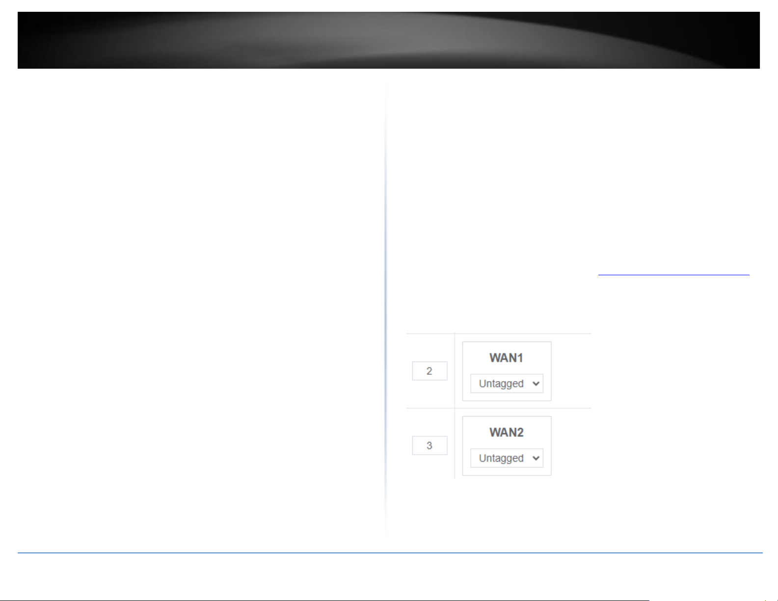
WAN VLAN Tagging
Some ISPs require VLAN tag assignment of a specific VLAN ID when for Internet access
or other services. You can follow the steps below to assign a specific VLAN ID to the
WAN interface.
1. Log into your router management page (see “Access your router management page”
on page 8).
2. Click on Network and click VLAN.
3. Under the VID, you can enter the VID required by your ISP and set the WAN interface
to tagged or untagged. Click Apply to save and commit the changes.
Page 23
© Copyright 2023 TRENDnet. All Rights Reserved.
15
TRENDnet User’s Guide
TEW-929DRU
IPv6 settings
Network > IPv6
IPv6 (Internet Protocol Version 6) is a new protocol that significantly increases the
number of available Internet public IP addresses due to the 128-bit IP address structure
versus IPv4 32-bit address structure. In addition, there are several integrated
enhancements compared to the most commonly used and well known IPv4 (Internet
Protocol Version 4) such as:
• Integrated IPsec – Better Security
• Integrated Quality of Service (QoS) – Lower latency for real-time applications
• Higher Efficiency of Routing – Less transmission overhead and smaller routing
tables
• Easier configuration of addressing
Note: In order to use IPv6 Internet connection settings, it is required that your ISP
provide you with the IPv6 service. Please contact your ISP for availability and more
information about the IPv6 service.
1. Log into your router management page (see “Access your router management page”
on page 8).
2. Click on Network and click on IPv6.
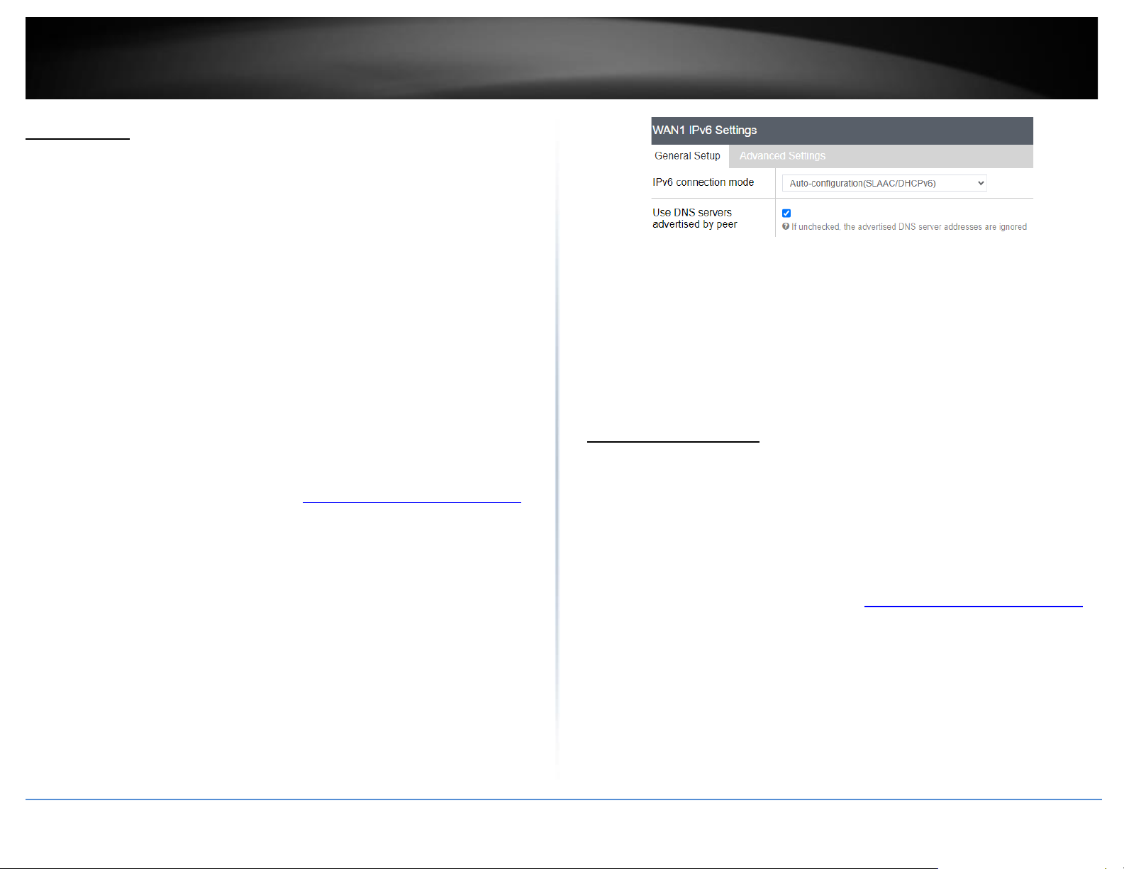
3. Review the IPv6 Internet Connection settings and enter information settings specified
by your ISP. Complete all of the fields required by your ISP and click Apply to save and
commit the changes.
Note: Please contact your ISP for IPv6 service availability.
Select the IPv6 WAN connection type provided by your ISP.
• Static IPv6
• Auto-configuration (SLAAC/DHCPv6)
• PPPoE
• Link-Local Only
Virtual LANs (VLANs)
Network > VLAN
Your router supports port-based 802.1Q VLANs as well inter-VLAN routing. VLANs can
be assigned different IP address interfaces in which the router can route be between
VLAN IP subnets.
Create a port-based VLAN
1. Log into your router management page (see “Access your router management page”
on page 6).
2. Click on Network and click VLAN.
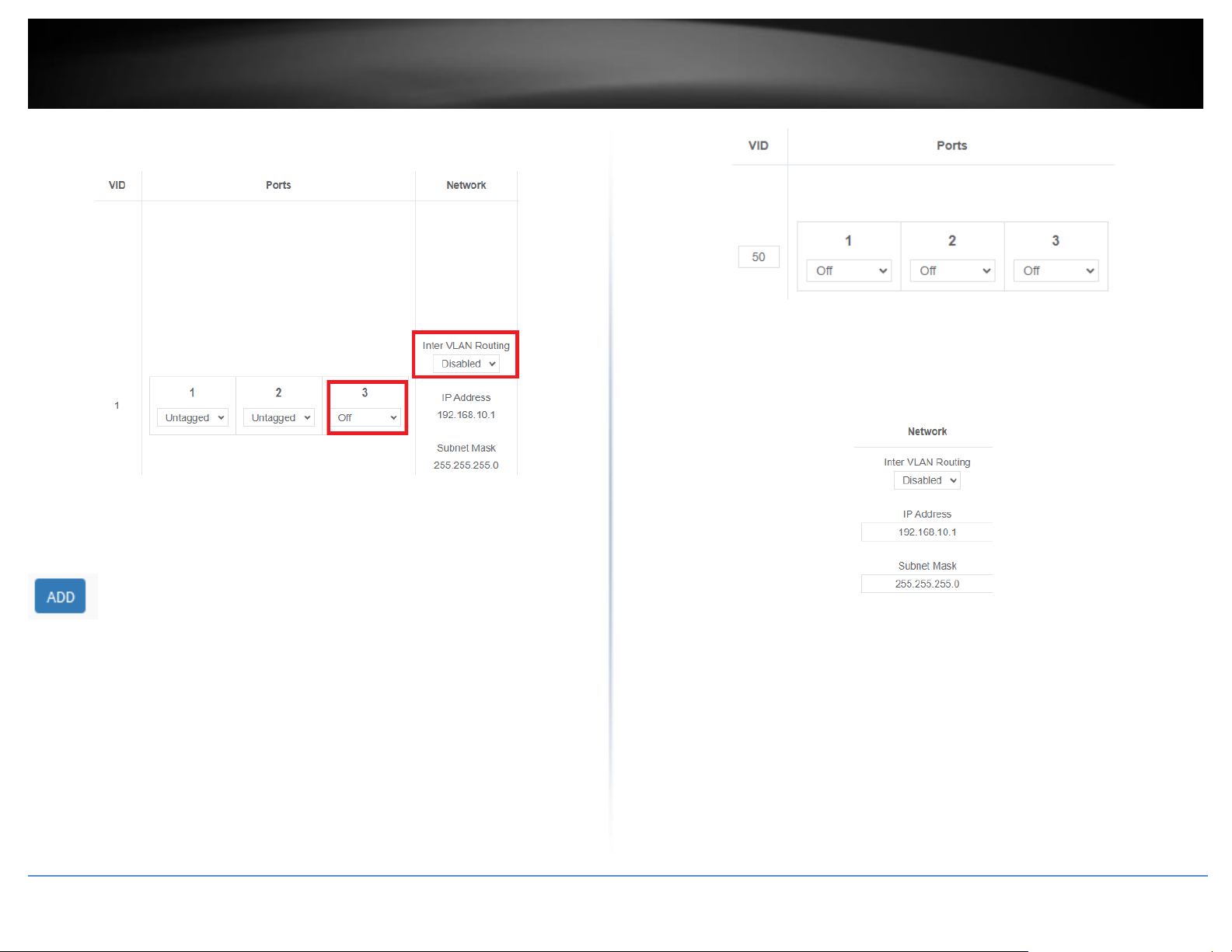
3. Before assigning which untagged and tagged VLAN member ports are assigned to a
new VLAN, the ports must be set to Off in the default VLAN VID: 1 (LAN). Also, click
the Inter VLAN Routing drop-down list and select Enabled to enable communication
between the LAN and other VLAN interfaces. Click Apply to save and commit the
changes. Example: We will remove port 3 from the default VLAN VID: 1 (LAN) interface
Page 24
© Copyright 2023 TRENDnet. All Rights Reserved.
16
TRENDnet User’s Guide
TEW-929DRU
so these ports can be re-assigned as untagged member ports of new VLANs in example
below.
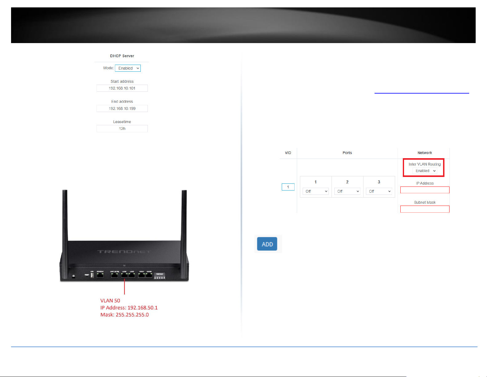
4. To create a new 802.1Q VLAN, under the VLANs section, click Add.
5. Under VID, enter the VLAN ID to assign to the new VLAN (4-4094, VLAN IDs 1-3 are
reserved for use with the default LAN, WAN1, WAN2 interfaces) and set the untagged
VLAN member ports. Example: In the example below, we will create a new VLAN with
VLAN ID: 50 and assign ports 2 as untagged member ports.
6. Enter the VLAN IP interface configuration under IP Address and Subnet Mask.
Example: In the example below, we will enter the VLAN 50 interface IP address as
192.168.50.1 and subnet mask 255.255.255.0.
7. Under DHCP Server, click the Mode drop-down list and select Enabled to enable the
DHCP server on the VLAN. Click Apply to save and commit the changes.
Example: In the example below, we will enable the DHCP server on VLAN 50 and leave IP
address range and lease defaults. This will assign a DHCP IP range of 101-199 to ensure
any devices connected to this VLAN obtain IP address information via DHCP.
Page 25
© Copyright 2023 TRENDnet. All Rights Reserved.
17
TRENDnet User’s Guide
TEW-929DRU
If following the port-based VLAN configuration example, any computers or devices
connecting to ports 2 will obtain 192.168.50.x/255.255.255.0 address settings and use
the VLAN 50 IP interface 192.168.50.1 as the Internet gateway and gateway to other
local IP subnets.
Create a port-based VLAN with 802.1Q tagging
Your router supports 802.1Q VLAN tagging/trunking to other 802.1Q VLAN devices such
as managed switches.
1. Log into your router management page (see “Access your router management page”
on page 6).
2. Click on Network and click VLAN.
3. Under VLAN VID:1 (LAN), click the Inter VLAN Routing drop-down list and select
Enabled and click Apply to commit and save the changes.
4. To create a new 802.1Q VLAN, under the VLANs section, click Add.
Page 26
© Copyright 2023 TRENDnet. All Rights Reserved.
18
TRENDnet User’s Guide
TEW-929DRU
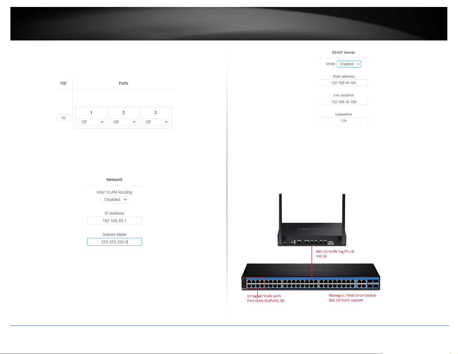
5. Under VID, enter the VLAN ID to assign to the new VLAN (4-4094, VLAN IDs 1-3 are
reserved for use with the default LAN, WAN1, WAN2 interfaces) and set the tagged
VLAN member port. Example: In the example below, we will create a new VLAN with
VLAN ID: 50 and assign port 8 as a tagged VLAN member port.
6. Enter the VLAN IP interface configuration under IP Address and Subnet Mask.
Example: In the example below, we will enter the VLAN 50 interface IP address as
192.168.50.1 and subnet mask 255.255.255.0.
7. Under DHCP Server, click the Mode drop-down list and select Enabled to enable the
DHCP server on the VLAN. Click Apply to save and commit the changes.
Example: In the example below, we will enable the DHCP server on VLAN 50 and leave IP
address range and lease defaults. This will assign a DHCP IP range of 101-199 to ensure
any devices connected to this VLAN obtain IP address information via DHCP.
If following the 802.1Q VLAN configuration example, a managed/web smart switch with
802.1Q VLAN support can be connected and pass VLAN 50 traffic between the router
and switch. Any computers or devices connecting to the untagged VLAN ports (PVID: 50)
on the managed/web smart will obtain 192.168.50.x/255.255.255.0 address settings
and use the VLAN 50 IP interface 192.168.50.1 as the Internet gateway and gateway to
other local IP subnets. Additional VLANs can be created on the router and switch in
which 802.1Q VLAN traffic can pass through the same single 802.1Q VLAN tag/trunk
link.
Page 27
© Copyright 2023 TRENDnet. All Rights Reserved.
19
TRENDnet User’s Guide
TEW-929DRU
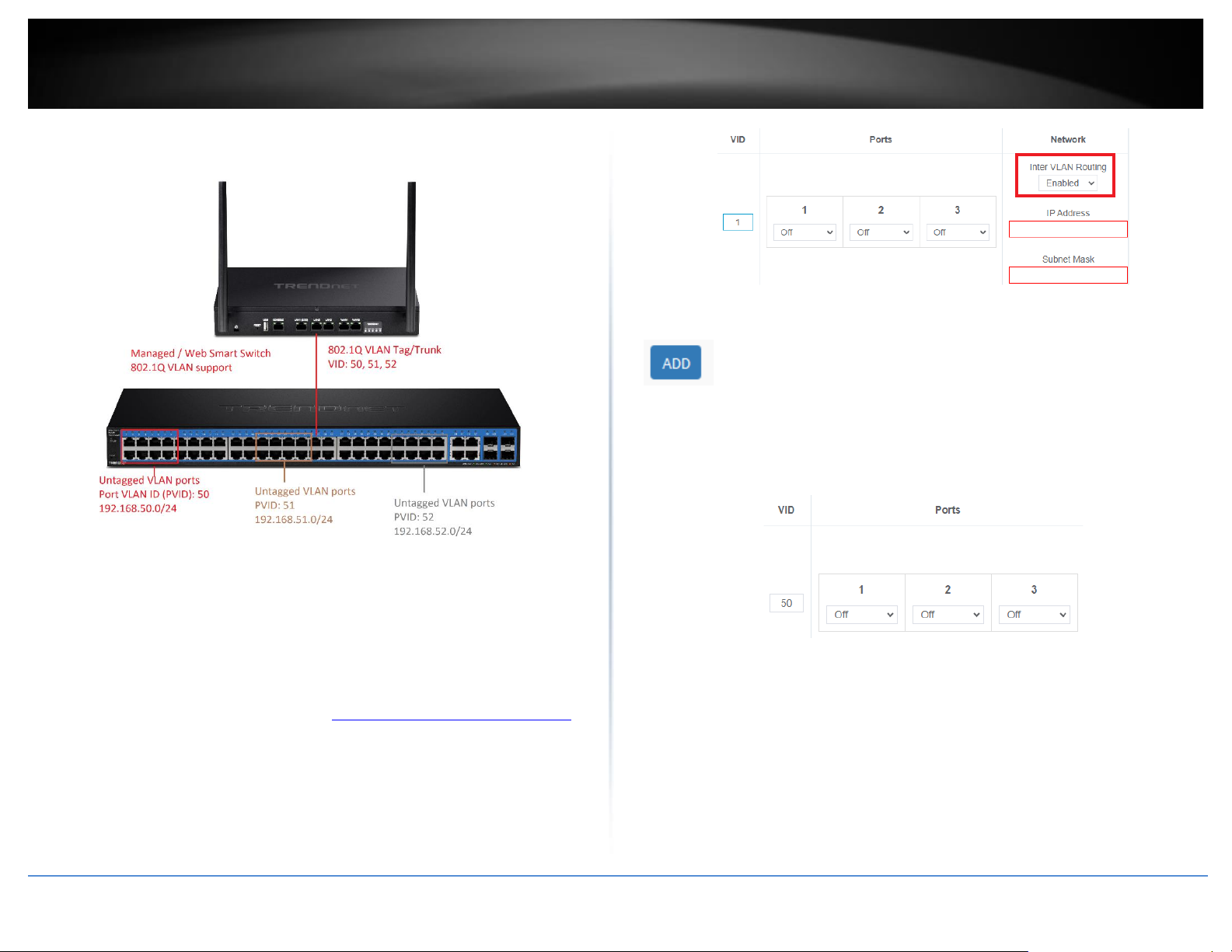
Example below of multiple VLANs configured and passing traffic through the same
802.1Q VLAN tag/trunk link.
Assigning VLAN IDs to Wireless SSIDs
Your router supports assigning specific VLAN IDs to wireless SSIDs to extend VLAN traffic
manageability and control to your router wireless network. By default, primary and
multiple SSIDs are assigned to the LAN (VLAN 1) IP network.
1. Log into your router management page (see “Access your router management page”
on page 8).
2. Click on Network and click VLAN.
3. Under VLAN VID:1 (LAN), click the Inter VLAN Routing drop-down list and select
Enabled and click Apply to commit and save the changes.
4. To create a new 802.1Q VLAN, under the VLANs section, click Add.
5. Under VID, enter the VLAN ID to assign to the new VLAN (4-4094, VLAN IDs 1-3 are
reserved for use with the default LAN, WAN1, WAN2 interfaces) and set the tagged
VLAN member port. Example: In the example below, we will create a new VLAN with
VLAN ID: 50 and assign port 8 as a tagged VLAN member port.
6. Enter the VLAN IP interface configuration under IP Address and Subnet Mask.
Example: In the example below, we will enter the VLAN 50 interface IP address as
192.168.50.1 and subnet mask 255.255.255.0.
Page 28
© Copyright 2023 TRENDnet. All Rights Reserved.
20
TRENDnet User’s Guide
TEW-929DRU
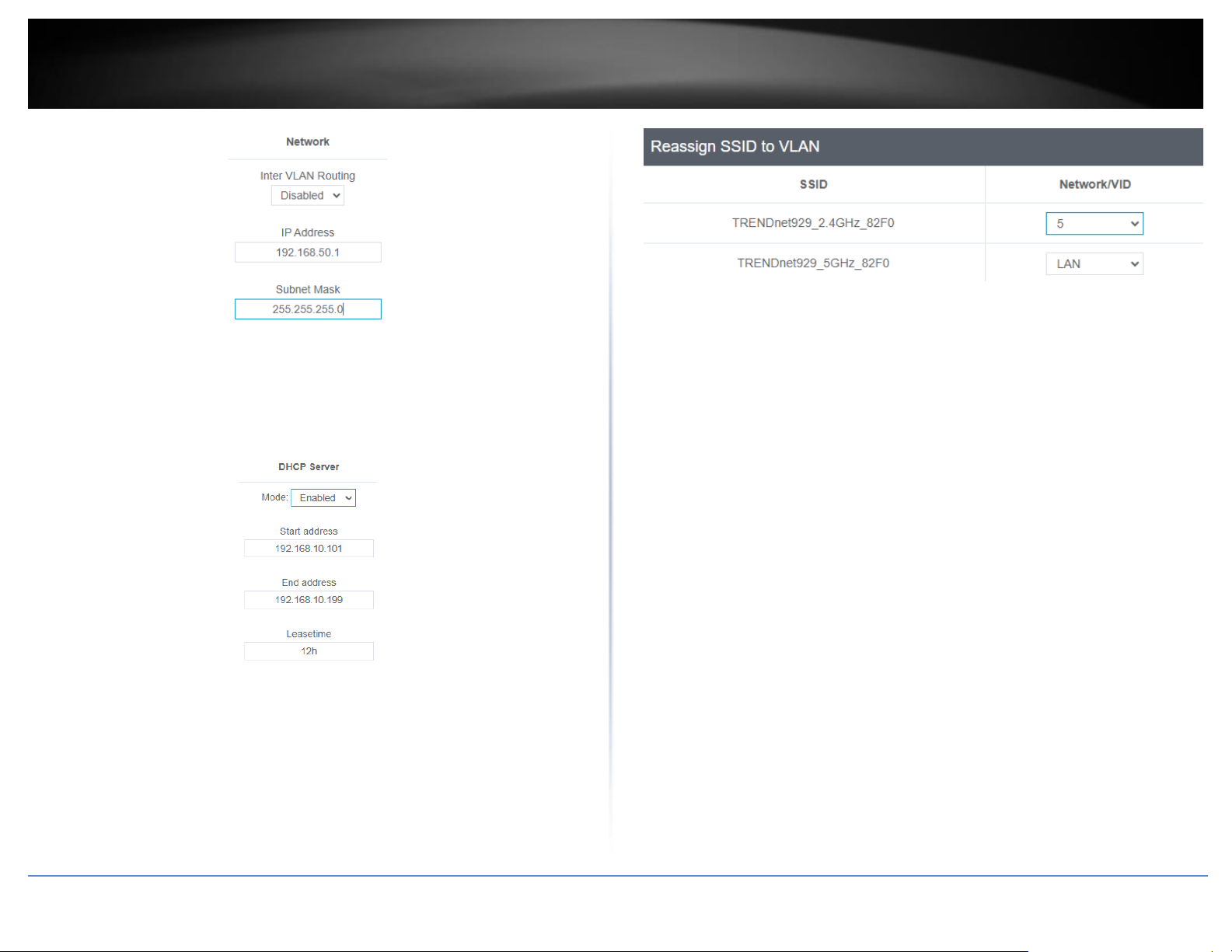
7. Under DHCP Server, click the Mode drop-down list and select Enabled to enable the
DHCP server on the VLAN. Click Apply to save and commit the changes.
Example: In the example below, we will enable the DHCP server on VLAN 50 and leave IP
address range and lease defaults. This will assign a DHCP IP range of 101-199 to ensure
any devices connected to this VLAN obtain IP address information via DHCP.
8. Under Reassign SSID to VLAN, next to the SSID you would like to assign the new VLAN
ID, click the Network/VID drop-down list and select the VLAN ID. Click Apply to save
and commit the changes.
If following the 802.1Q VLAN configuration example, a managed/web smart switch with
802.1Q VLAN support can be connected and pass VLAN 50 traffic between the router
and switch and 2.4GHz wireless SSID. Any computers or devices connecting to the
untagged VLAN ports (PVID: 50) on the managed/web smart will obtain
192.168.50.x/255.255.255.0 address settings and use the VLAN 50 IP interface
192.168.50.1 as the Internet gateway and gateway to other local IP subnets. Any
wireless computers or devices connecting to the 2.4GHz wireless SSID will also obtain
192.168.50.x/255.255.255.0 address settings while connecting to 5GHz1 or 5GHz2 SSIDs
will remain on the LAN network. Additional VLANs can be created on the router and
switch in which 802.1Q VLAN traffic can pass through the same single 802.1Q VLAN
tag/trunk link. Multiple SSIDs will appear in this section when enabled and configured.
Guest network SSID does not apply.
Below is a reference of the additional VLAN settings if you choose to make other
configuration changes to these sections.
• VID – The VLAN ID assigned to a specific VLAN.
• Ports 1-3 – Configure port VLAN membership settings.
o Untagged – Default setting. Sets port membership as untagged and
allows connectivity to network devices such as computers. The router
will use the internal port VLAN ID (PVID) to forward VLAN traffic
accordingly to these ports based on their untagged VLAN membership.
o Tagged – Sets port membership as tagged and used for VLAN tag or
trunk links to other VLAN aware devices such as managed switches or
access points.
o Off – Removes port membership from a specific VLAN.
Page 29
© Copyright 2023 TRENDnet. All Rights Reserved.
21
TRENDnet User’s Guide
TEW-929DRU
• Inter VLAN Routing – Allows communication between local network
interfaces/IP subnets such as the LAN and VLAN interfaces.
• IP Address/Subnet Mask – The IP address and subnet mask assigned to a
specific VLAN interface.
• Mode – Configures the DHCP server settings for a specific VLAN interface.
o Disabled – Disables DHCP on a specific VLAN interface.
o Enabled – Enables the internal DHCP server on a specific VLAN
interface. Allows you to set the IP address range/pool, lease time,
WINS/DNS servers, and local domain name for the DHCP server.
o Relay – Enables DHCP relay on a specific VLAN interface and forwards
DHCP requests on the VLAN interface to an external DHCP server IP
address (e.g. 192.168.50.20).
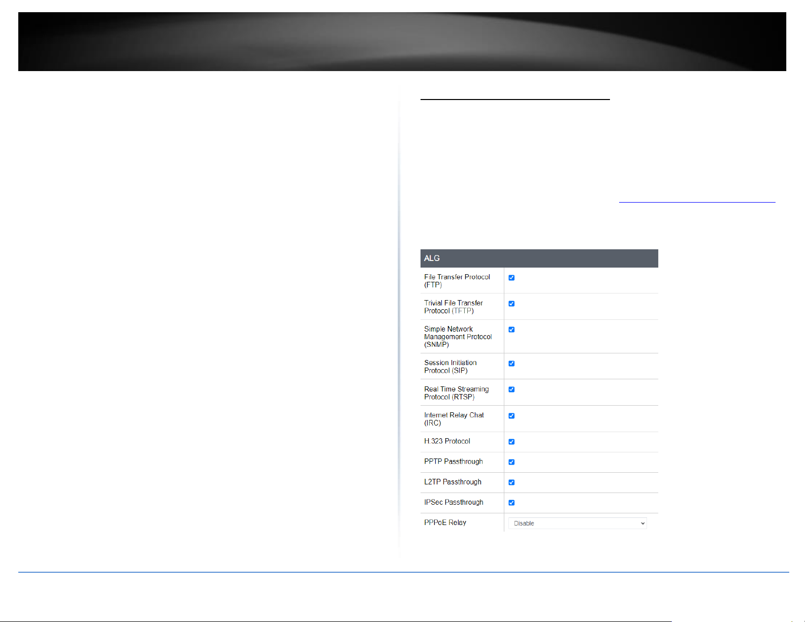
Application layer gateway (ALG)
Security > ALG
You may want to configure your router to allow computers the use of specific high layer
applications or service sessions to pass through. Application Layer Gateways (ALG)
allows you to easily enable or disable these applications to pass through your router.
Note: It is recommended to leave these settings enabled.
1. Log into your router management page (see “Access your router management page”
on page 6).
2. Click on Security and click on ALG.
3. Review the applications. Click Apply to save and commit the changes.
Page 30
© Copyright 2023 TRENDnet. All Rights Reserved.
22
TRENDnet User’s Guide
TEW-929DRU
UPnP and NAT-PMP
Security > UPnP
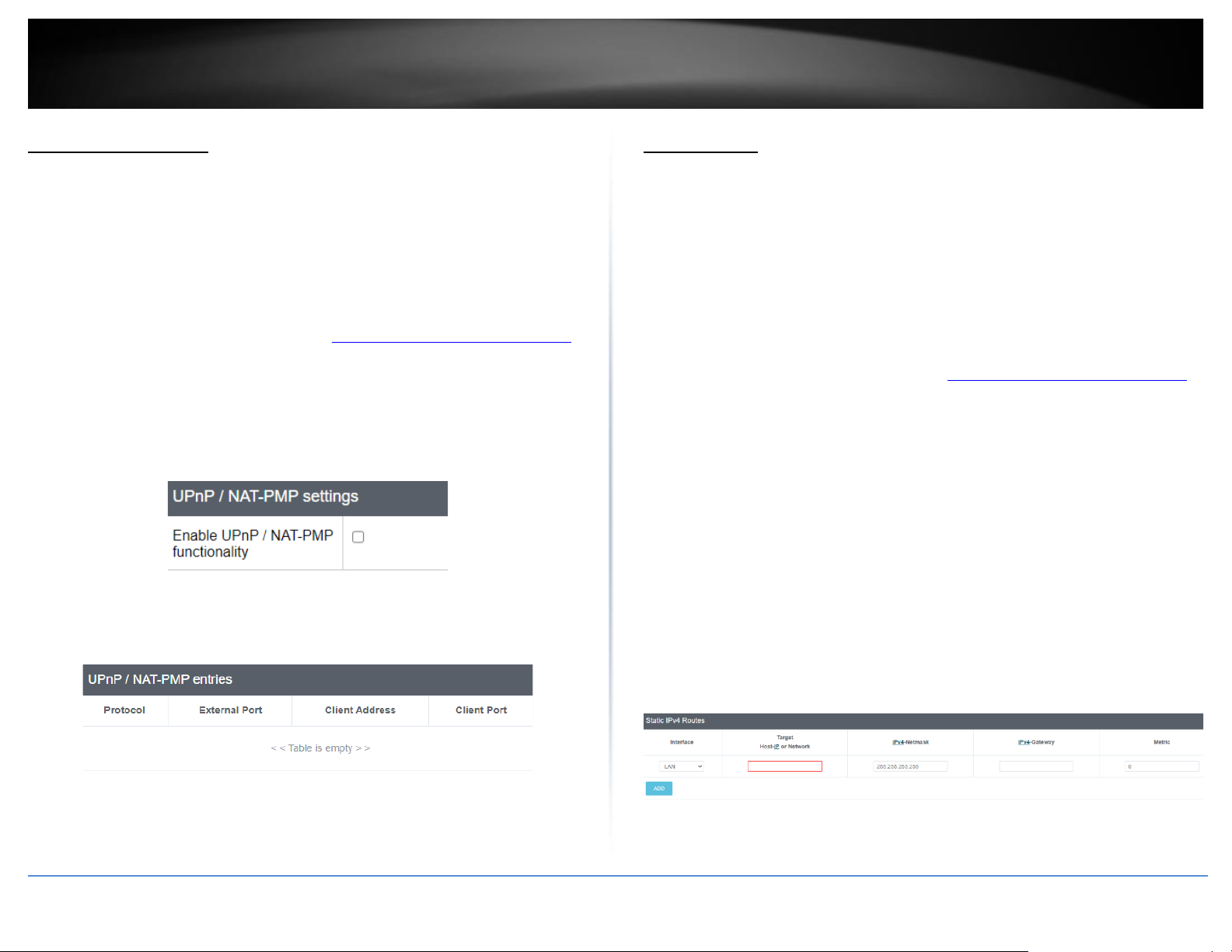
UPnP (Universal Plug and Play) and NAT-PMP (NAT Port Mapping Protocol) allows
devices connected to a network to discover each other and automatically open the
connections or services for specific applications (e.g. instant messenger, online gaming
applications, etc.) UPnP and NAT-PMP is disabled on your router by default and should
only be enabled to allow specific applications required by your computers or devices to
allow connections through your router as they are needed.
1. Log into your router management page (see “Access your router management page”
on page 6).
2. Click on Security and click on UPnP / NAT-PMP.
3. Under the UPnP / NAT-PMP section, check the Enable UPnP / NAT-PMP functionality
option. Click Apply to save and commit the changes.
Note: When UPnP/NAT-PMP is enabled, you can check the currently open connections in
the UPnP/NAT-PMP entries table..
Static routes
Network > Routing
You may want set up your router to route computers or devices on your network to
other local networks through other routers. Generally, different networks can be
determined by the IP addressing assigned to those networks. Generally speaking and for
the case of this example, your network may have 192.168.10.x IP addressing and
another network may have 192.168.20.x IP addressing and because the IP addressing of
these two networks are different, they are separate IP networks. In order to
communicate between the two separate networks, static routing needs to be
configured.
1. Log into your router management page (see “Access your router management page”
on page 6).
2. Click on Network and click on Routing.
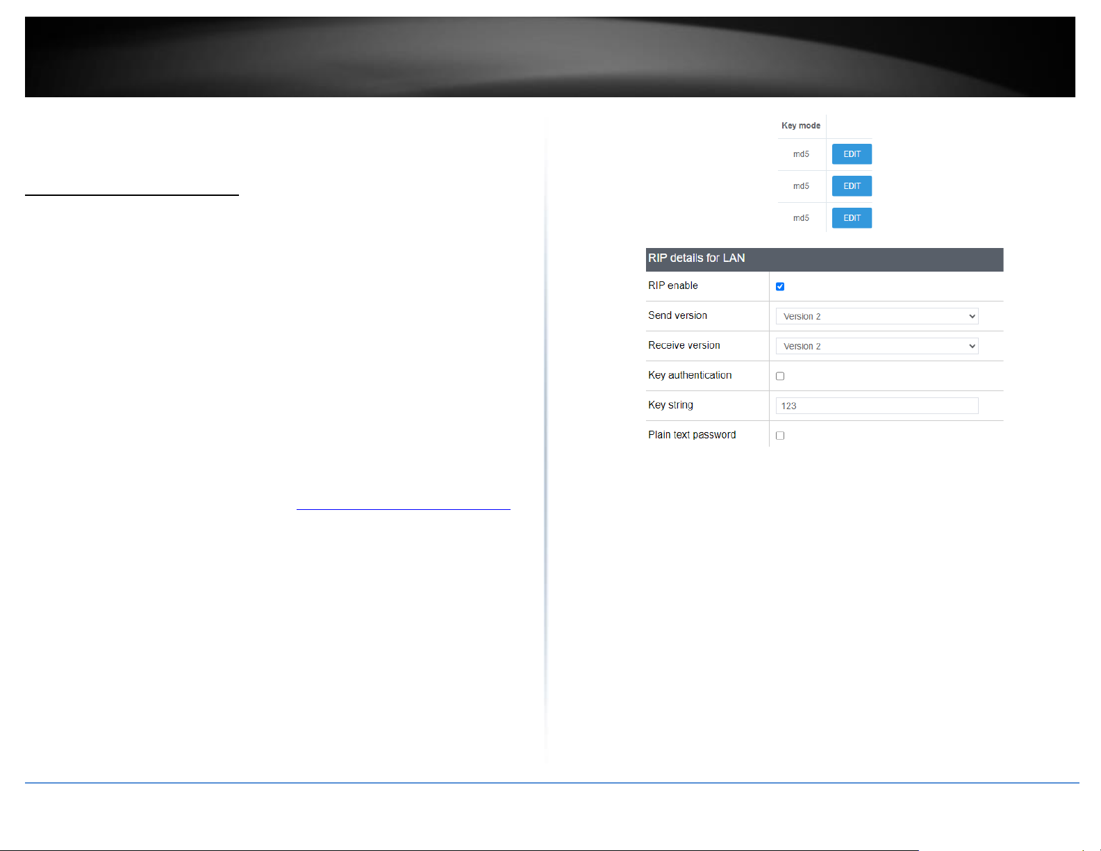
3. Review the Routing section. Click Add to add the new static route. Click Apply to save
and commit the changes.
• Interface – Select the interface to assign the route.
• Target Host-IP or Network: Enter the IP network address of the destination
network for the route. (e.g. 192.168.20.0)
• IPv4-Netmask: Enter the subnet mask of the destination network for the
route.(e.g. 255.255.255.0)
• IPv4-Gateway: Enter the gateway to the destination network for the route.
(e.g. 192.168.10.2)
• Metric: Enter the metric or priority of the route. The metric range is 0-9999, the
lowest number 0 being the highest priority.
Page 31
© Copyright 2023 TRENDnet. All Rights Reserved.
23
TRENDnet User’s Guide
TEW-929DRU
You can check the current routing table under Status > Routes under Active IPv6Routes.
Dynamic routing protocols
Network > Routing > RIP
You may want set up your router to route computers or devices on your network to
other local networks through other routers. Generally, different networks can be
determined by the IP addressing assigned to those networks. Generally speaking and for
the case of an example, your network may have 192.168.10.x IP addressing and another
network may have 192.168.20.x IP addressing and because the IP addressing of these
two networks are different, they are separate networks. In order to communicate
between the two separate networks, static routing needs to be configured. Below is an
example diagram where routing is needed for devices and computers on your network
to access the other network. If you have other routing devices that support dynamic
routing protocol, you can enable these routing protocols on your router to learn and
automatically generate the routes needed between these networks.
Routing Information Protocol (RIP)
Network > Routing > RIP
1. Log into your router management page (see “Access your router management page”
on page 6).
2. Click on Network, click on Routing, and click on the RIP tab.
3. Review the RIP Routing section. To save changes to this section, click Apply to
command save your changes.
• RIP enable: Check the option to enable the RIP dynamic routing protocol globally
on the router.
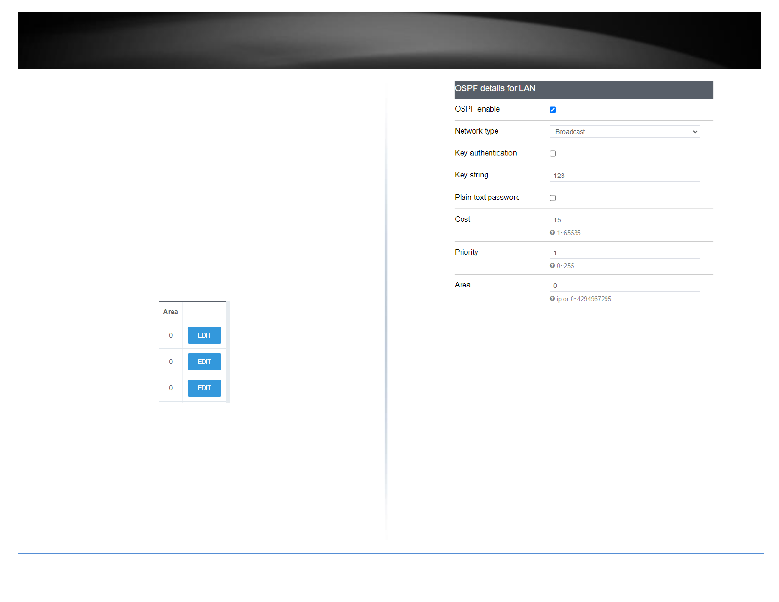
In the Overview table, you can enable and configure RIP for each interface by clicking
Edit next to the interface.
• RIP enable: Check the option to enable RIP on the specified interface.
• protocols and redistribute the routing information using OSPF protocol.
• Send version – Select the RIP protocol version to send.
• Receive version – Select the RIP protocol version to receive.
• Key Authentication – Enables MD5 authentication on all RIP messages sent and
received.
• Key String – If authentication is enabled, enter the authentication key
string/password to use for RIP messages sent and received.
• Plain text password – This option will set the password to be send in clear text
instead of using the MD5 hash. This setting is not recommended.
You can check the current routing table under Status > Routes under Active IPv6-
Routes.
Page 32
© Copyright 2023 TRENDnet. All Rights Reserved.
24
TRENDnet User’s Guide
TEW-929DRU
OSPF (Open Shortest Path First)
Network > Routing > OSPF
1. Log into your router management page (see “Access your router management page”
on page 6).
2. Click on Network, click on Routing, and click on the OSPF tab.
3. Review the OSPF Routing section. To save changes to this section, click Apply to
commit and save your changes.
In the Overview table, you can enable and configure RIP for each interface by clicking
Edit next to the interface.
• OSPF enable: Check the option to enable OSPF dynamic routing globally on the
router.
• Router ID: Enter the OSPF router ID.
• OSPF enable: Check the option to enable OSPF dynamic routing on the specified
interface.
• Network type: Select the OSPF network type. Select only Point to Point or Point
to Multi-point if connecting to your networking using PPP protocol, otherwise
select Broadcast. If only exchanging OSPF routing information to one other
device, select Non-Broadcast and enter in the Neighbor IP address at the bottom.
• Key authentication – Enables MD5 authentication on all OSPF messages sent and
received.
• Key string – If authentication is enabled, enter the authentication key
string/password to use for OSPF messages sent and received.
• Plain text password – This option will set the password to be send in clear text
instead of using the MD5 hash. This setting is not recommended.
• Cost – Enter the OSPF cost value.
• Priority – Enter the OSPF priority value.
• Area - Enter the area id for OSPF.
You can check the current routing table under Status > Routes under Active IPv6Routes.
Page 33
© Copyright 2023 TRENDnet. All Rights Reserved.
25
TRENDnet User’s Guide
TEW-929DRU
Quality of Service (QoS)
Multi-WAN/QoS > QoS
The router supports up to four QoS priority queues for traffic classification and priority.
1. Log into your router management page (see “Access your router management page”
on page 6).
2. Click on Multi-WAN/QoS and click on QoS.
3. Under QoS settings, review the settings below. When complete, click Apply to save
and commit your changes.
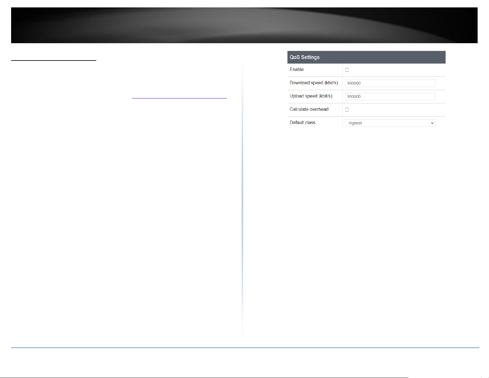
QoS Settings
• Enable: Check the enable option to Enable QoS.
• Download speed (kbit/s): Enter the maximum download speed provided by your
ISP in kilobits per sec. It is important to set this value accurately.
Note: If your multiple mode is set to load balancing, you can combine the total
download bandwidth of both WAN connections.
• Upload speed (kbit/s): Enter the maximum upload speed provided by your ISP in
kilobits per sec. It is important to set this value accurately.
• Note: If your multiple mode is set to load balancing, you can combine the total
upload bandwidth of both WAN connections.
• Calculate overhead – Typically, when this option is unchecked/disabled, the
overhead value will not be added to the upload and download speeds entered in
the fields. When this option is checked/enabled, the total overhead calculation is
included in the total upload/download speed specified to ensure the values
entered are the absolute maximum value limits entered.
• Default class – When QoS is enabled, select the default priority class used for all
other traffic when QoS after all specific QoS classification rules have been
applied. You can typically set this to Low or Medium.
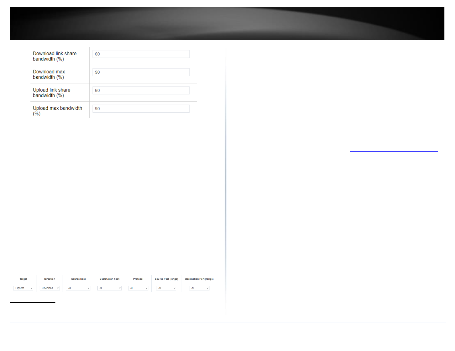
Classes – The QoS priority classes define the bandwidth maximum limits of total
bandwidth that can be used and total bandwidth that can be shared for a particular
class. Note: Typically, you do not need to modify the QoS priority class percentage
settings.
• Download link share bandwidth (%) – This defines the guaranteed bandwidth
% from the total download speed defined in the QoS settings. The class setting
will attempt to guarantee this bandwidth % minimum limit is allocated.
• Download max bandwidth (%) – This defines the maximum bandwidth %
allowable from the total download speed defined in the QoS settings. This class
setting is the maximum bandwidth % limit that can be allocated above the link
share bandwidth %.
• Upload link share bandwidth (%) – This defines the guaranteed bandwidth %
from the total upload speed defined in the QoS settings. The class setting will
attempt to guarantee this bandwidth % minimum limit is allocated.
• Upload max bandwidth (%) – This defines the maximum bandwidth %
allowable from the total upload speed defined in the QoS settings. This class
setting is the maximum bandwidth % limit that can be allocated above the link
share bandwidth %.
Page 34
© Copyright 2023 TRENDnet. All Rights Reserved.
26
TRENDnet User’s Guide
TEW-929DRU
Classification Rules
Click Add to create a new QoS classification rule. When complete, click Apply to save
and commit your changes.
• Target – Select the QoS priority class to apply to the rule.
• Direction – Select the direction of traffic in which to apply the QoS
classification, Download (Inbound Traffic) or Upload (Outbound Traffic).
• Source Host – Click the drop-down list to select All (any IP address), a specific
source host IP address from the list or select Custom to define a particular
source IP address not listed.
• Destination Host– Click the drop-down list to select All (any IP address), a
specific destination host IP address from the list or select Custom to define a
particular destination IP address not listed.
• Protocol – Click the drop-down to select the type of traffic to apply the QoS
classification rule. All/TCP/UDP/ICMP or custom to specify a particular protocol
not listed.
• Source Port (range) – Enter the source port or source port range to apply the
QoS classification rule.
• Destination Port (range) – Enter the source port or source port range to apply
the QoS classification rule.
•
Dynamic DNS
System > Dynamic DNS
When using a dynamic IP/DHCP WAN type from your ISP where your public IP or
Internet IP address always changes, dynamic DNS provides a method of accessing your
router or network remotely over the Internet for devices such as IP cameras, storage, or
computers hosted on the local LAN side of your router. Dynamic DNS services do thi by
assigning a custom hostname or DNS name for you to reference. Your router will send
updates to the dynamic DNS service provider if the WAN or Internet IP address(es)
change providing the emulation of a virtual fixed IP address that you can always
reference to access your router over the Internet.
Note: First, you will need to sign up for one of the DDNS service providers listed in the
Server Address drop-down list.
1. Sign up for one of the DDNS available service providers list under Server Address.
(e.g. no-ip.com, dyndns.org etc.)
2. Log into your router management page (see “Access your router management page”
on page 6).
3. Click on System and click on Dynamic DNS.
4. Review the DDNS settings below. When complete, click Apply to save and commit
your changes.
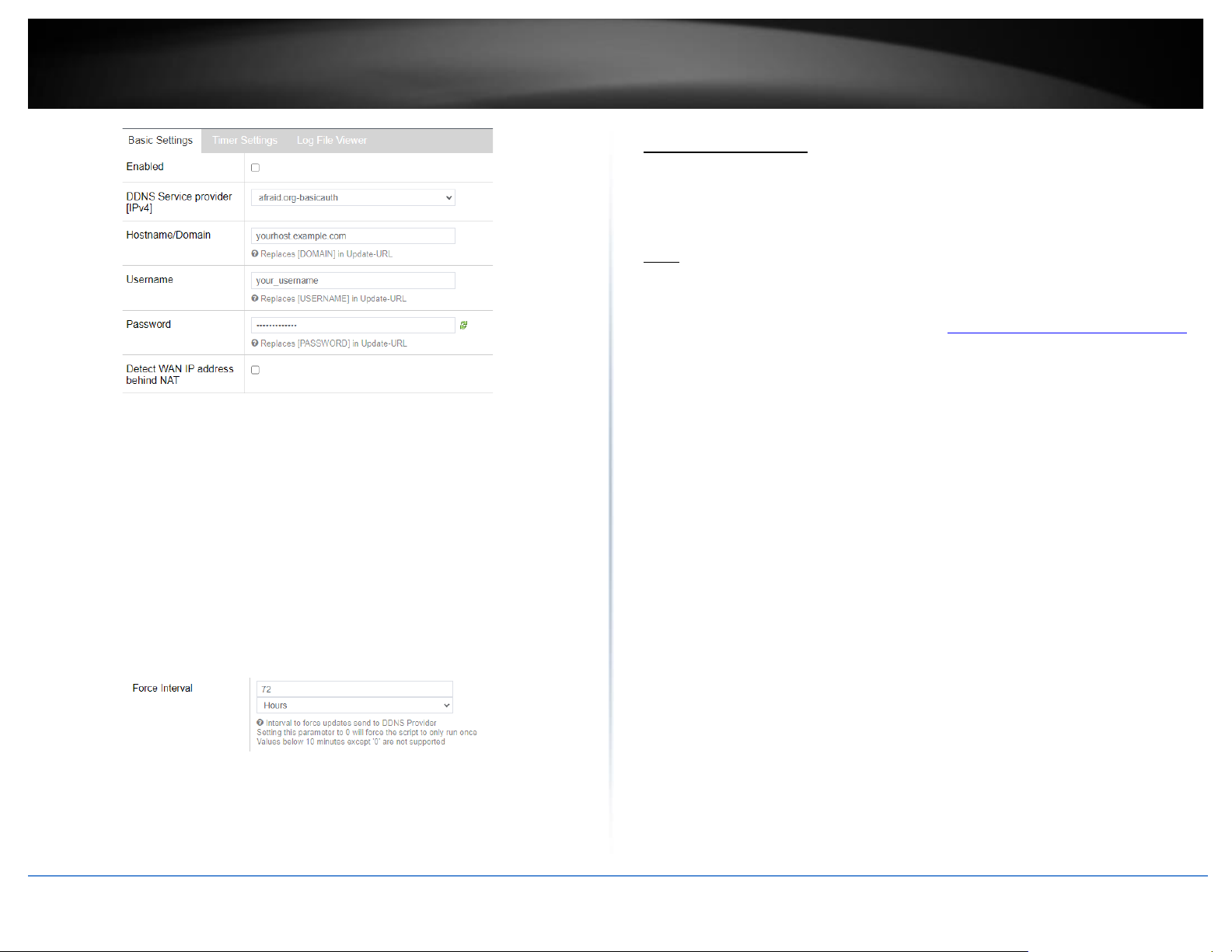
• Enabled – Check the enabled option to enable dynamic DNS on the selected WAN
interface.
• DDNS Provider [IPv4]: Click the drop-down list Select your DDNS service.
• Hostname/Domain: Enter the custom hostname or DNS name you created with
DDNS account. (e.g. trendnet.ddns.net)
• Username: The user name needed to login to your Dynamic DNS service account.
• Password: This is the password to login to your Dynamic DNS service account.
• Detect WAN IP address behind NAT: This will allow your router to detect the IP
address
Page 35
© Copyright 2023 TRENDnet. All Rights Reserved.
27
TRENDnet User’s Guide
TEW-929DRU
Below is a reference of the additional Dynamic DNS settings if you choose to make other
configuration changes to these sections.
Timer Settings
Allows you to configure a specified interval to force your router to send a DDNS update
to your DDNS service provider.
Note: Please note that it is recommended not to set the interval too low and send
updates too often as this may not meet the minimum requirements of your DDNS service
provider client update policy.
• Force Interval – Enter a value in days, hours, or minutes.
Note: The smallest interval allowed is 10 minutes. Setting the value to 0 will
force your router to send a DDNS update only once and will not resend any
more DDNS updates for the specified WAN.
Log File Viewer
Allows you to view the log status for Dynamic DNS of your router.
• Refresh – Clears any logged displayed and reload new logs
File sharing server
System > Samba (USB)
Your router’s USB port can be used to share files through the network when a USB
storage device is connected on the back USB port. The router supports Samba (SMB) file
sharing protocol and is compatible with SMB/CIFS.
Note: Only FAT32 or NTFS file formats are supported, up to 4TB max. storage size.
After you have connected your USB storage device:
1. Log into your router management page (see “Access your router management page”
on page 6).
2. Click on System and click on Samba (USB).
3. Review the settings below. When complete, click Apply to save and commit your
changes.
Note: By default, the Samba server name is set to TEW-829DRU or the LAN IP address
may also be used default LAN IP: 192.168.10.1. To change the Samba server name, you
can modify this setting under Administrator > System and edit the Host Name setting.
Samba General Settings
• Enable – Check the enable option to enable Samba file sharing.
• Description: Enter a description for the server.
• Workgroup: Enter the workgroup name. It is recommended to keep the standard
default “WORKGROUP”. If you change this setting, you will need to change the
workgroup name on all computers in your network that are allowed access to the
USB storage in order to discover it automatically. Otherwise, you will need to
access the server by IP address.
• Login Required – Selecting No will not require computers to login when accessing
the USB share. Select Yes will require computers to enter a user name and
password when accessing the USB share and user account can be modified under
the Samba Users list. This user account will have full read/write permissions on
the USB share.
Page 36
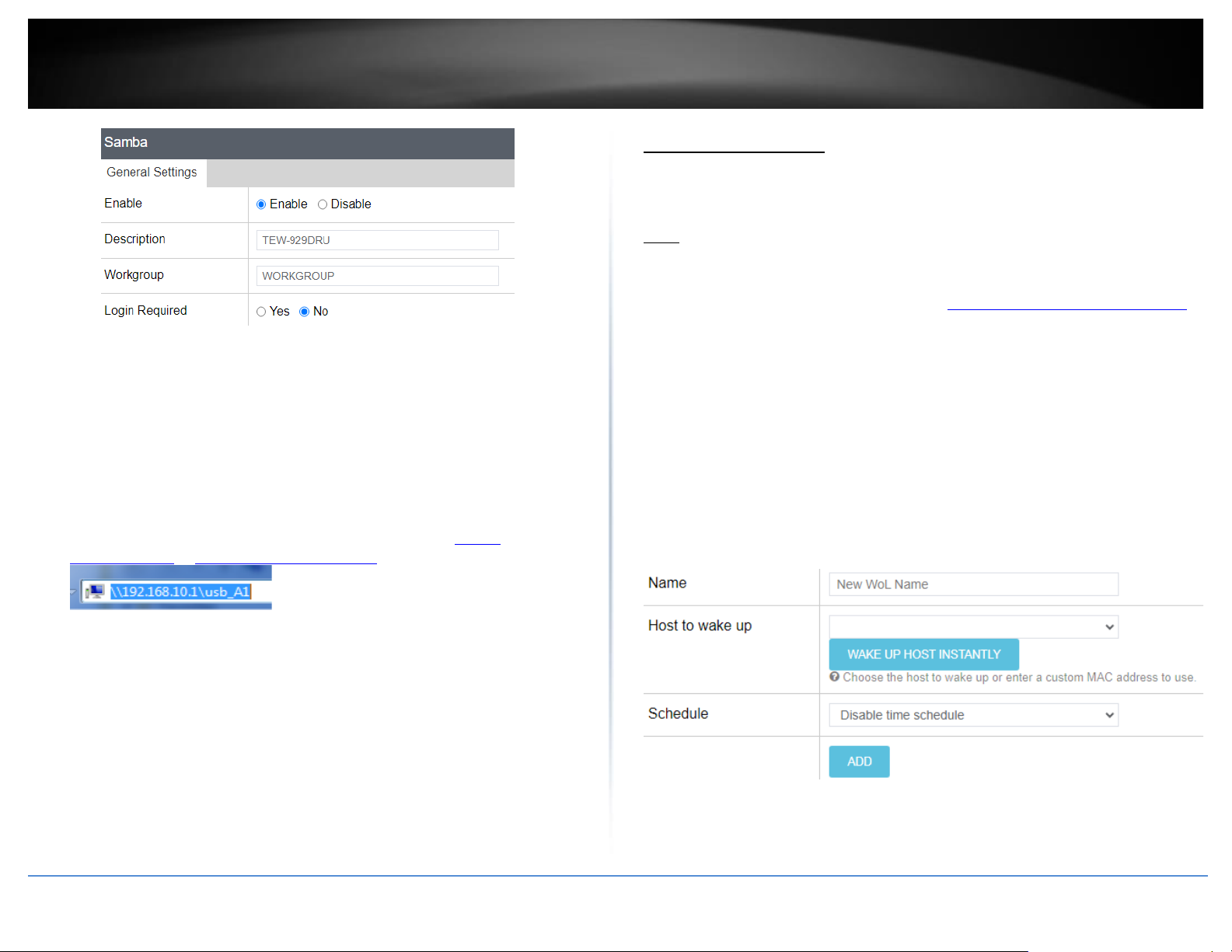
© Copyright 2023 TRENDnet. All Rights Reserved.
28
TRENDnet User’s Guide
TEW-929DRU
Samba Users
• User Name: Enter the user name to be used to access the USB share.
• Password: Enter the password to be used to access the USB share.
Shared Devices
• Device Name: Displays the USB storage device name.
• Shared Name: Displays the Samba share name used to access the USB share over
the network.
Example: You can access the USB share by typing in the path \\TEW-
929DRU\usb_A1 or \\<routerIPaddress>\usb_A1.
• Size – Displays the total size of the USB storage device.
• Used – Displayed the storage space currently used on the USB storage device.
• Available – Displays the storage space currently available on the USB storage
device.
• Eject Device – Clicking the Eject button will allow you to safely remove/dismount
and disconnect the USB storage device.
Wake on LAN (WoL)
System > WoL (Wake on LAN)
Wake on LAN (WoL) is used to remotely wake up or turn on device that support the WoL
feature from your router.
Note: In order for the WoL feature to work, the device must support the WoL and it must
be enabled configured properly on the device.
1. Log into your router management page (see “Access your router management page”
on page 6).
2. Click on System and click on WoL
3. Review the settings below. When complete, click Apply to save and commit your
changes.
• Name: Input the name of the WoL
• Host to wake up: Click the drop-down list to select a computer/device from the
list or manually enter the MAC address of the device. Clicking the WAKE UP HOST
INSTANTLY button will immediately send a wake up message to the WoL device.
• Add new WoL schedule: Allows you to select a schedule when to send a wake up
message to the WoL device.
Page 37

© Copyright 2023 TRENDnet. All Rights Reserved.
29
TRENDnet User’s Guide
TEW-929DRU
Wireless Networking and Security
Wireless Settings
Wireless > Wireless (2.4GHz or 5GHz)
This section covers the wireless settings of your router such as wireless network names
(SSIDs), channels, 802.11 mode, and other wireless settings.
1. Log into your router management page (see “Access your router management page”
on page 6).
2. Click on Network and click on the wireless band you would like to configure Wireless
(2.4GHz or 5GHz)
3. Review the settings below. When complete, click Apply to save and commit your
changes.
Primary SSID – This tab involves the configuration parameters for the primary SSID for a
specific wireless band.
• Device Configuration
o General Setup
▪ Status – Displays current information about the wireless
radio/band such as SSID, BSSID/wireless MAC address,
encryption, operating channel, transmit power, bitrate, and
country/region.
▪ Enable wireless radio – This option is checked by default to
enable the wireless radio/band. Unchecking this option will
disable the wireless radio/band including all additional SSIDs
configured on the specific band.
▪ Turn off wireless radio by schedule – Allows you to assign a
time schedule when the band should be turned on and off.
Note: Modifying the channel settings will force currently
connected wireless client devices to disconnect and reconnect
to your router’s wireless networks.
o Advanced Settings
▪ Mode – By default, 802.11b/g/n and 802.11a/n/ac modes are
configured to ensure the best compatibility with wireless
client devices. These settings will allow all wireless client
devices to connect to you router’s wireless networks
including devices that support older standards such as
802.11a/b/g.
Note: If older slower wireless client devices connect to your
wireless network, this may reduce the speed and performance
of all other wireless client devices connecting to the same
wireless network.
▪ HT mode: Select the appropriate channel width for your
wireless network. For greater 2.4GHz performance/data rate
capability, you can select Auto 20/40MHz (Options: 20MHz or
Auto 20/40MHz). It is recommended to use the default
channel bandwidth settings.
For greater 5GHz performance/data rate capability, you can
select Auto 20/40/80MHz (Options: 20MHz, Auto 20/40MHz,
Auto 20/40/80MHz). It is recommended to use the default
channel width settings.
Note: Please note that the default settings may provide more
stability than the higher channel bandwidth settings such as
Auto 20/40MHz or Auto 20/40/80MHz for connectivity in busy
wireless environments where there are several wireless
networks in the area.
• 20 MHz – This mode operates using a single 20MHz
channel for wireless devices connecting at 802.11n
on both 2.4GHz and 5GHz. This setting may provide
Page 38
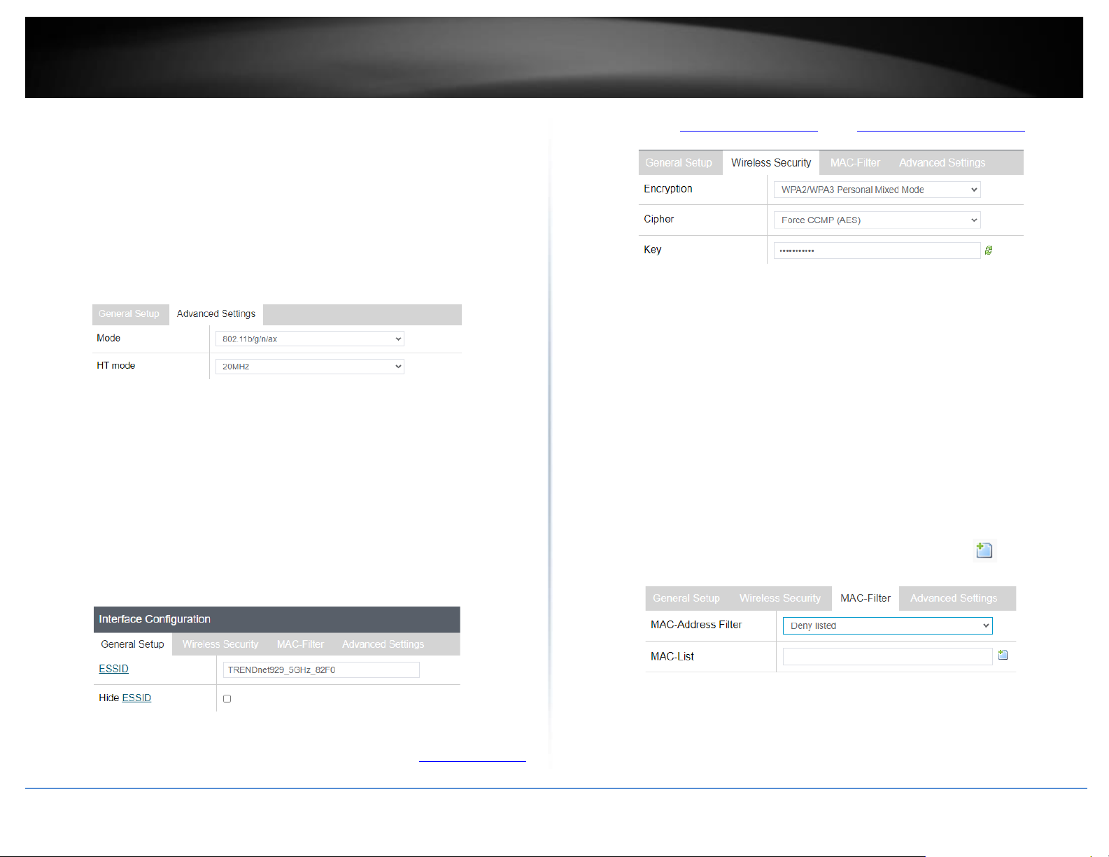
© Copyright 2023 TRENDnet. All Rights Reserved.
30
TRENDnet User’s Guide
TEW-929DRU
more stability than 20/40MHz (Auto) for connectivity
in busy wireless environments where there are
several neighboring wireless networks in the area.
• Auto 20/40MHz (11n) or Auto 20/40/80MHz
(11ac/11ax) –When this setting is active, this mode
is capable of providing higher performance only if
the wireless devices support the channel width
settings. Enabling Auto 20/40MHz or Auto 20/40/80
MHz typically results in substantial performance
increases when connecting an 802.11ac/n wireless
client.
• Interface Configuration
o General Setup
▪ ESSID – This is wireless network name setting for the primary
SSID band. This name will differentiate your wireless network
from other neighboring wireless networks so you can identify
and connect your wireless client devices. Enter the wireless
network name to assign to the wireless band.
▪ Hide ESSID – Checking this option will hide your wireless
network name from being discovered by wireless client
devices scanning for available wireless networks. This will not
disable the wireless band or network and wireless client
devices can still connect. It only hides the network name from
being discovered.
o Wireless Security – Allows you to configure the wireless
encryption/security for the wireless band. See the “How to choose the
type of wireless security” and “Secure your wireless network” sections
for details configuring wireless security.
o MAC-Filter – This feature adds additional security to your wireless
band by allowing you to enter a list of specific MAC addresses that can
either be allowed to connect (Allow listed only) or blocked (Deny
listed) from connecting to your wireless network. This feature must be
specified on each wireless band.
▪ MAC-Address Filter
• Disable - Disables MAC address filtering on the
wireless band.
• Allow listed only (Whitelist) – Sets the MAC filter
action to allow only the MAC addresses listed and
deny all others on the wireless band.
• Deny listed (Blacklist) – Sets the MAC filter action to
deny only the MAC addresses listed and allow all
others on the wireless band.
▪ MAC- List – Enter the MAC addresses to allow or deny. For
each additional MAC address entries, click .
(e.g. a1:b2:c3:d4:e5:f6)
o Advanced Settings
▪ Separate Clients – By default, this option is left unchecked
and allows all wireless client devices that are connected to
the same wireless SSID to communicate with other wireless
client devices. Checking this option will block communication
between wireless client devices connecting with other
Page 39
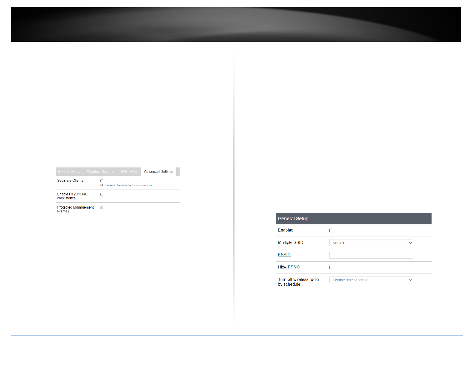
© Copyright 2023 TRENDnet. All Rights Reserved.
31
TRENDnet User’s Guide
TEW-929DRU
wireless client devices. This feature is also known as L2
isolation or L2 client isolation.
▪ WMM Mode – This feature enables Wi-Fi Multimedia QoS
prioritization for wireless client devices that support WMM
using the default priority level settings. Unchecking this
option will disable WMM QoS on the wireless band.
▪ Enable HT20/40 coexistence – Applies to 2.4GHz band only.
This option is enabled by default to ensure connection
stability on the 2.4GHz band. When this option is enabled, the
radio will attempt to operate at the higher 40MHz channel
width mode if there are not too many neighboring wireless
networks. If the current wireless environment is too busy the
radio will automatically operate at the lower 20MHz channel
width mode. Unchecking this option forces the radio to
operate at the higher 40MHz channel which cause instability
if there are too many neighboring 2.4GHz wireless networks.
Multiple SSID - This tab involves the configuration parameters for the additional SSIDs
for a specific wireless band. Up to 7 additional SSIDs can be created per wireless band.
You can view a summarized list of the current operating SSID and channels under Status
> Overview in the Wireless section.
• General Setup
o Enabled – Checking this option will enable the additional SSID on the
specific wireless band. Before checking Enabled, click the Multiple SSID
drop-down and select which index number SSID to configure.
o Multiple SSID – Click the drop-down to select the index number SSID
to configure, then check Enabled.
o ESSID – This is wireless network name setting for the additional SSID
band. This name will differentiate your wireless network from other
neighboring wireless networks so you can identify and connect your
wireless client devices. Enter the wireless network name to assign to
the additional SSID.
o Hide ESSID – Checking this option will hide your wireless network
name from being discovered by wireless client devices scanning for
available wireless networks. This will not disable the additional SSID
and wireless client devices can still connect. It only hides the network
name from being discovered.
o Turn off wireless radio by schedule – Allows you to assign a time
schedule when the band should be turned on and off.
• Wireless Security – Allows you to configure the wireless encryption/security for
the additional SSID. See the “How to choose the type of wireless security” and
Page 40
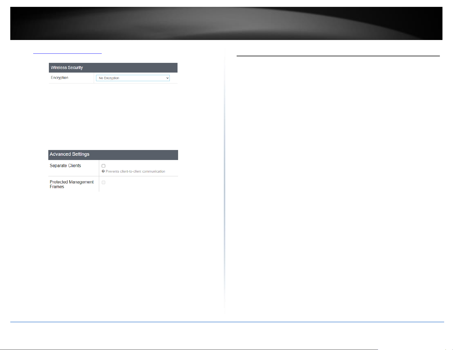
© Copyright 2023 TRENDnet. All Rights Reserved.
32
TRENDnet User’s Guide
TEW-929DRU
“Secure your wireless network” sections for details configuring wireless
security.
• Advanced Settings
o Separate Clients – By default, this option is left unchecked and allows
all wireless client devices that are connected to the same wireless SSID
to communicate with other wireless client devices. Checking this
option will block communication between wireless client devices
connecting with other wireless client devices. This feature is also
known as L2 isolation or L2 client isolation.
o Protected Management Frames – This feature enables protection for
multicast management action frames.
How to choose the type of security for your wireless network
Setting up wireless security is very important. Leaving your wireless network open and
unsecure could expose your entire network and personal files to outsiders. TRENDnet
recommends reading through this entire section and setting up wireless security on your
new access point.
There are a few different wireless security types supported in wireless networking each
having its own characteristics which may be more suitable for your wireless network
taking into consideration compatibility, performance, as well as the security strength
along with using older wireless networking hardware (also called legacy hardware).
It is strongly recommended to enable wireless security to prevent unwanted users from
accessing your network and network resources (personal documents, media, etc.).
In general, it is recommended that you choose the security type with the highest
strength and performance supported by the wireless computers and devices in your
network. Please review the security types to determine which one you should use for
your network.
Wireless Encryption Types
• WPA/WPA2-Personal: This setting provides the router with the ability to detect
wireless devices using either WPA or WPA2 encryption. Your wireless network will
automatically change the encryption setting based on the first wireless device
connected. For example, if the first wireless client that connects to your wireless
network uses WPA encryption your wireless network will use WPA encryption. Only
when all wireless clients disconnect to the network and a wireless client with WPA2
encryption connects your wireless network will then change to WPA2 encryption.
Note: WPA2 encryption supports 802.11n speeds and WPA encryption will limit
your connection speeds to 54Mbps
• WPA2-Personal: This is the most secure wireless encryption available today, similar
to WPA encryption but more robust. This encryption standard also supports the
highest connection speeds. TRENDnet recommends setting your router to this
encryption standard. If you find that one of your wireless network devices does not
support WPA2 encryption, then set your router to either WPA or WPA-Auto
encryption.
Note: Check the specifications of your wireless network adapters and wireless
appliances to verify the highest level of encryption supported. Below is brief
comparison chart of the wireless security types and the recommended
configuration depending on which type you choose for your wireless network.
• WPA3-Personal: This is the latest wireless encryption. It is similar to WPA2
encryption, but more robust. This encryption standard also supports the highest
Page 41
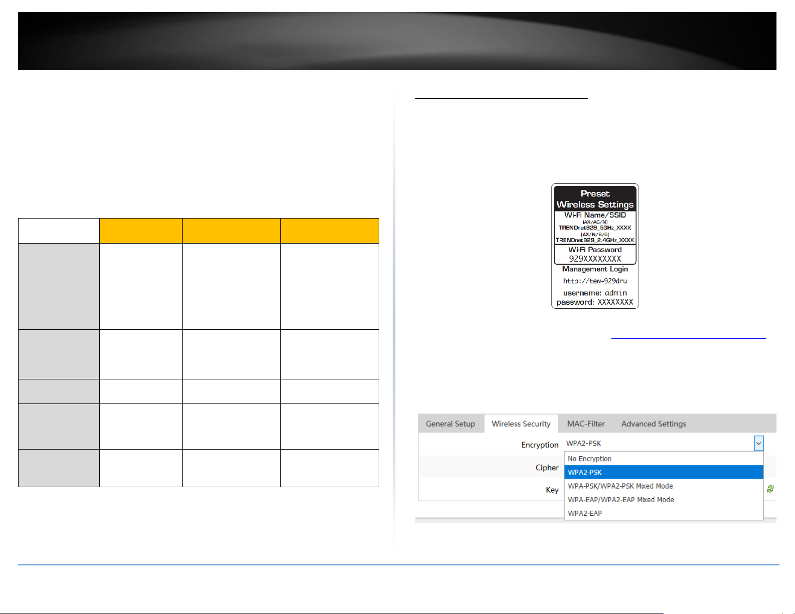
© Copyright 2023 TRENDnet. All Rights Reserved.
33
TRENDnet User’s Guide
TEW-929DRU
possible connection speed. TRENDnet recommends setting your router to this
encryption standard. If you find that one of your wireless network devices does not
support WPA3 encryption, then set your router to either WPA2 or WPA encryption.
• WPA2/WPA3-Personal: This setting provides the router with the ability to detect
wireless devices using either WPA2 or WPA3 encryption. Your wireless network will
automatically change the encryption setting based on the first wireless device
connected.
Note: Check the specifications of your wireless network adapters and wireless
appliances to verify the highest level of encryption supported. Below is brief
comparison chart of the wireless security types and the recommended
configuration depending on which type you choose for your wireless network
Security
Standard
WPA
WPA2
WPA3
Compatible
Wireless
Standards
802.11a/b/g
(802.11ac/802.11
n devices will
operate at
802.11g/802.11a
to connect using
this standard)
802.11a/b/g/n/ac
IEEE 802.11 n/ac/ax
Highest
Performance
Under This
Setting
Up to 54Mbps
Up to 450Mbps
(11n) and up to
1.3Gbps (11ac)*
Up to 600Mbps
(11n) and up to
1.2Gbps (11ax)*
Encryption
Strength
Medium
High
Highest
Additional
Options
TKIP or AES,
Preshared Key or
RADIUS
TKIP or AES,
Preshared Key or
RADIUS
AES
Recommended
Configuration
TKIP
Preshared Key
8-63 characters
AES
Preshared Key
8-63 characters
AES
Preshared Key
8-63 characters
*Dependent on the maximum 802.11n/ac/ax data rate
supported by the device (150Mbps, 300Mbps, 450Mbps,
867Mbps, 1.3Gbps, 2.4Gbps, or 4.8Gbps)
Secure your wireless network
Network > Wireless 2.4GHz / 5GHz1 / 5GHz2
By default, your router is pre-configured with wireless network names (SSIDs) and a
wireless encryption key using WPA2-PSK (AES). The predefined wireless network name
and security can be found on the sticker on the side of the router or on the device label
at the bottom of the router. The following sections involve changing the default wireless
security settings and encryption key.
1. Log into your router management page (see “Access your router management page”
on page 6).
2. Click on Network and click on the wireless band you would like to configure, Wireless
2.4GHz / 5GHz1.
3. Under Interface Configuration and in the Wireless Security tab, click on the
Encryption drop-down list to select your wireless security type.
Page 42
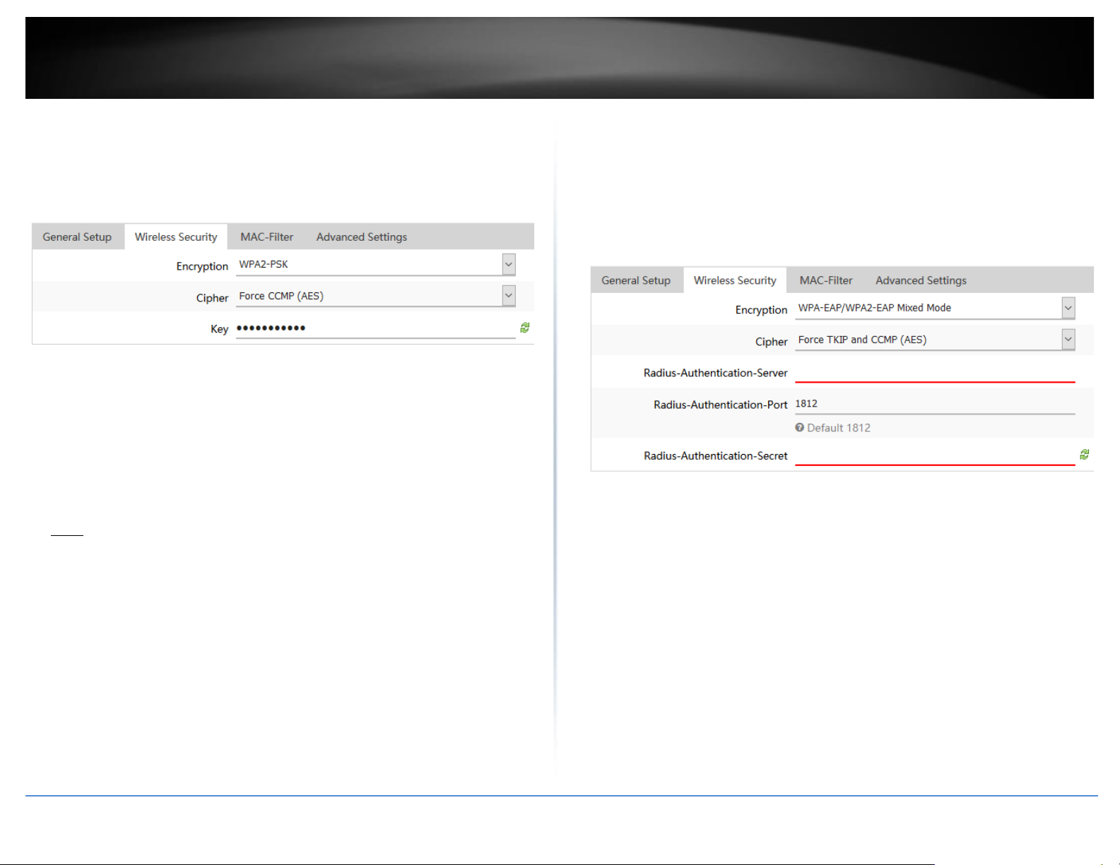
© Copyright 2023 TRENDnet. All Rights Reserved.
34
TRENDnet User’s Guide
TEW-929DRU
Selecting WPA2-PSK, WPA-PSK / WPA2-PSK Mixed Mode
(WPA2-PSK recommended):
In the Security Mode drop-down list, select WPA2-PSK or WPA-PSK / WPA2-PSK Mixed
Mode. Review the settings below. When complete, click Apply to save and commit your
changes.
The following section outlines options when selecting WPA2-PSK, or WPA-PSK / WPA2-
PSK Mixed Mode.
• Cipher: Select a Cipher Type to use.
o When selecting WPA-PSK / WPA2-PSK Mixed Mode security, it is recommended
to use Force TKIP and CCMP (AES).
o When selecting WPA2-PSKsecurity, it is recommended to use Force CCMP (AES).
Key: Enter the pre-shared key or passphrase. (8-63 alphanumeric characters
(a,b,C,?,*, /,1,2, etc.)
Note: This is the wireless password, pre-shared key, or passphrase wireless client
devices will use to connect to your wireless network.
Selecting WPA2-EAP, WPA-EAP / WPA2-EAP Mixed Mode
The following section outlines options when selecting WPA2-EAP or WPA-EAP / WPA2-
EAP Mixed Mode (EAP or RADIUS). This security type is also known as EAP (Extensible
Authentication Protocol) or RADIUS (Remote Authentication Dial-In User Service).
Review the settings below. When complete, click Apply to save and commit your
changes.
Note: This security type requires an external RADIUS server, Pre-Shared Key only requires
you to create a wireless password, pre-shared key, or passphrase.
• Cipher: Select a Cipher Type to use.
o When selecting WPA-EAP / WPA2-EAP Mixed Mode security, it is recommended
to use Force TKIP and CCMP (AES).
o When selecting WPA2-EAP security, it is recommended to use Force CCMP (AES).
• Radius-Authentication-Server: Enter the IP address of the RADIUS server. (e.g.
192.168.10.250)
• Radius-Authentication-Port: Enter the port your RADIUS server is configured to use
for RADIUS authentication.
Note: It is recommended to use port 1812 which is typical default port used for the
RADIUS service.
• Radius-Authentication-Secret: Enter the shared secret used to authorize your
router with your RADIUS server.
Page 43
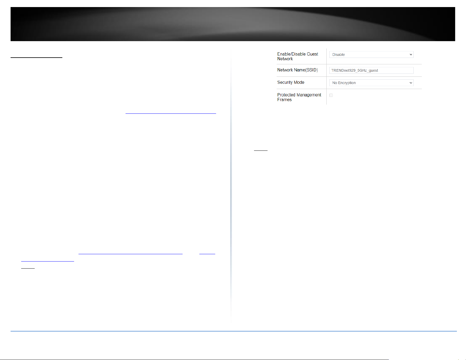
© Copyright 2023 TRENDnet. All Rights Reserved.
35
TRENDnet User’s Guide
TEW-929DRU
Guest Network
Wireless > Guest Network
Creating an isolated and separate wireless guest network on each wireless band allows
wireless clients to connect to your network for Internet access only and keep your local
LAN network safe by restricting guest access to your LAN network resources such as
shared documents and media files on your computers, network storage, and printers.
1. Log into your router management page (see “Access your router management page”
on page 6).
2. Click on Wireless and click on Guest Network.
3. Review the settings below. When complete, click Apply to save and commit your
changes.
First, choose the wireless band guest network you would like to configure, Wireless
2.4GHz Guest Network / 5GHz1 Guest Network / 5GHz2 Guest Network.
• Enable/Disable Guest Network – Selecting Enable turns on the wireless guest
network and selecting Disable turns off the wireless guest network for the specific
wireless band.
• Network Name(SSID) - This is wireless network name setting for the guest network.
This name will differentiate your wireless network from other neighboring wireless
networks so you can identify and connect your wireless client devices. Enter the
wireless network name to assign to the wireless guest network.
• Wireless Security – Allows you to configure the wireless encryption/security for the
wireless band. See the “How to choose the type of wireless security” and “Secure
your wireless network” sections for details configuring wireless security.
Note: You can only select WPA2-PSK or WPA-PSK / WPA2-PSK Mixed Mode. EAP
security cannot be applied to the wireless guest networks.
• Protected Management Frames - This feature enables protection for multicast
management action frames.
Guest DHCP – The wireless guest networks are assigned to a different IP address subnet
from the router LAN network for isolation.
• IPv4 Address – Enter the IP address interface for the wireless guest network. The IP
address subnet should be different from any other LAN or VLAN IP networks
configured on your router.
Note: The guest network IP address subnet only supports a class C subnet, subnet
mask 255.255.255.0.
• Start – Enter the starting value of DHCP IPv4 address range for the wireless guest
newtork. (e.g. If your guest network IPv4 address is 192.168.20.1, entering 120 will
define the first IP address of the DHCP pool is 192.168.20.120)
• End – Enter the ending value of DHCP IPv4 address range. (e.g. If your LAN IPv4
address is 192.168.20.1, entering 200 will define the last IP address of the DHCP
pool is 192.168.20.200)
• Lease Time – Enter the lease time in hours (h) or minutes (m) DHCP clients will hold
their IP address settings before automatically requesting a new lease (IP address
settings) from the internal DHCP server. (e.g. To specify 24 hours, enter 24h. To
specify 480 minutes, enter 480m.)
• Separate Clients – This option allows all wireless client devices that are connected
to the guest network wireless SSIDs to communicate with other wireless client
devices. Checking this option will block communication between wireless client
devices connecting with other wireless client devices. This feature is also known as
L2 isolation or L2 client isolation.
Page 44
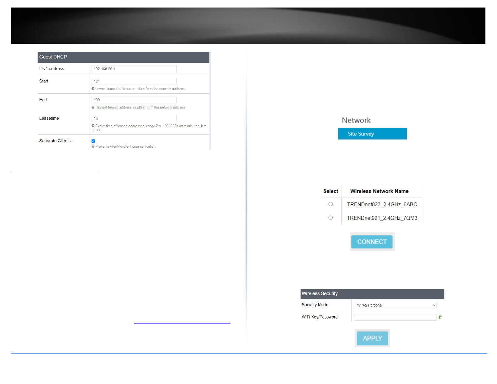
© Copyright 2023 TRENDnet. All Rights Reserved.
36
TRENDnet User’s Guide
TEW-929DRU
WiFi client bridge mode
System > Device Mode
The function of client bridge mode is to extend wireless connectivity to multiple wired
Ethernet client devices. A typical application where this mode may be used is in your
home entertainment/media center where multiple network enabled media devices
require Internet or network connectivity such as an HD smart TV, game console, set top
box, or DVR. The device will first establish connectivity (similar to a wireless enabled
client device such as a laptop or mobile phone) to your wireless network (typically
provided by a wireless router or access point) and bridge the connectivity to your
network over to the wired client devices using the LAN switch ports (1-8). After selecting
and applying this mode, click on Wireless > Wireless Network and click Site Survey to
scan for the wireless network to connect and enter the wireless security key (if required)
to establish connectivity to your network. After you have successfully set up the device
to connect to your wireless network, you can plug in the device in the area where you
would like to bridge network connectivity to wired client devices using the LAN switch
ports (1-8). In this mode, the device can only connect to one band at a time (2.4GHz or
5GHz) and will not provide any of the access control features typically provided in router
mode.
1. Log into your router management page (see “Access your router management page”
on page 6).
2. Click on Administrator and click on Device Mode.
Note: After changing the device mode to client bridge, the router will keep the existing
static LAN IP address. By default, the static LAN IP address: 192.168.10.1 /
255.255.255.0.
3. After the device completely apply the configuration changes and reboots, click
Network and click Site Survey to scan for available wireless networks.
4. Select the WiFi network to connect to in the list by clicking on the Select button next
to the WiFi network name or SSID and click Connect.
Note: If you do not find your WiFi network in the list, you can click Rescan to scan again
for networks.
5. If the network selected network requires a WiFi password/key, enter the key under
WiFi Key/Password and click Apply to save and commit your changes.
Note: The router keep the existing static LAN IP address settings after you have
connected to a WiFi network.
Page 45
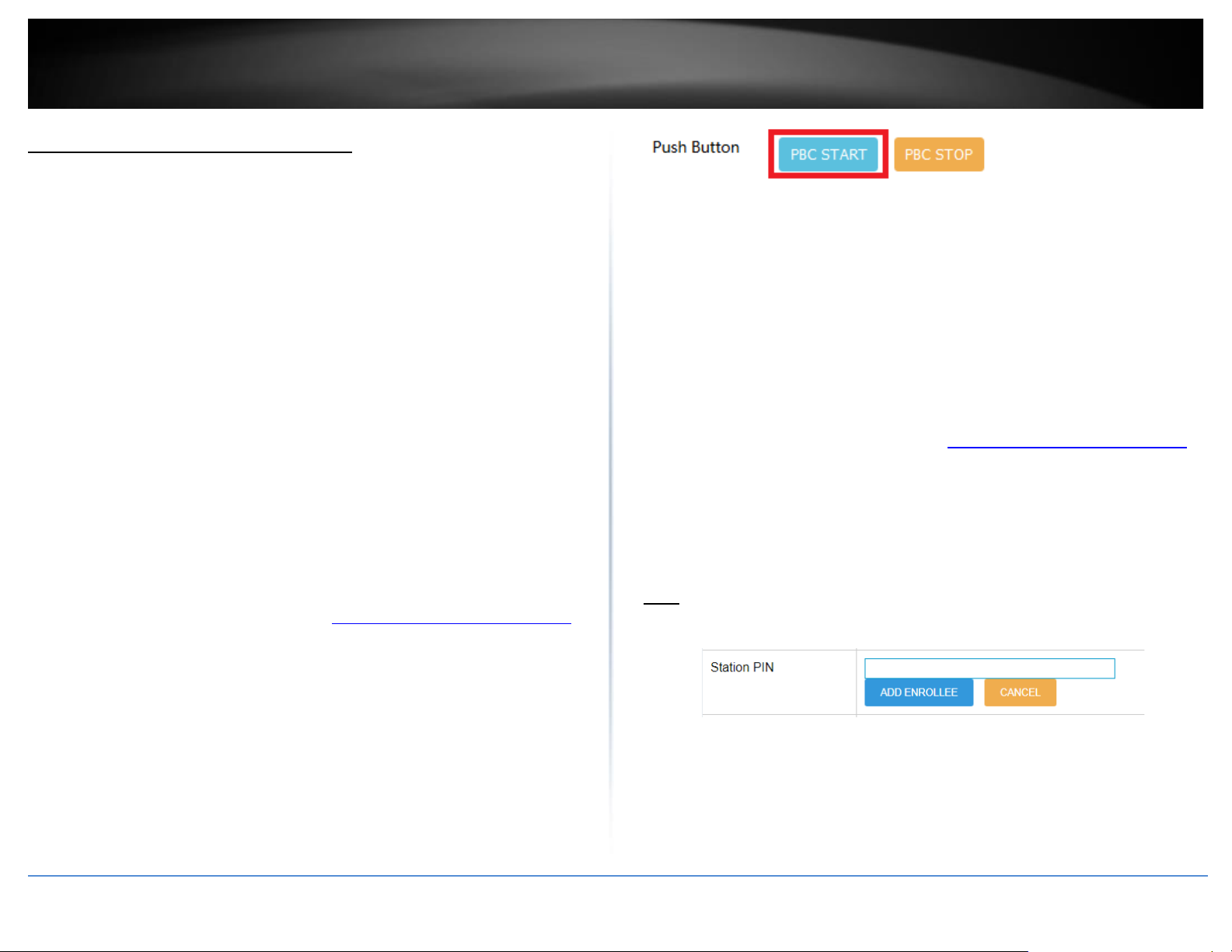
© Copyright 2023 TRENDnet. All Rights Reserved.
37
TRENDnet User’s Guide
TEW-929DRU
Connect wireless devices using WPS
Wireless > WPS
WPS (Wi-Fi Protected Setup) is a feature that makes it easy to connect devices to your
wireless network. If your wireless devices support WPS, you can use this feature to
easily add wireless devices to your network.
Note: You will not be able to use WPS if you set the Hide ESSID option to enabled under
Network > Wireless 2.4GHz / Wireless 5GHz1 / Wireless 5GHz2 sections.
There are two methods the WPS feature can easily connect your wireless devices to
your network.
• Virtual Push Button Configuration (PBC) method (Recommended)
• PIN (Personal Identification Number) Method - located in router management page
Note: Refer to your wireless client device documentation for details on the operation
of WPS.
PBC (Software/Virtual Push Button)
In addition to the hardware push button located physically on your router, the router
management page also has push button which is a software or virtual push button you
can click to activate WPS on your router.
1. Log into your router management page (see “Access your router management page”
on page 6).
2. Click on Wireless and click on WPS.
3. Click Enable to enable WPS and click Apply. WPS can also be enabled by wireless
band (2.4GHz / 5GHz) and External Registrar can also be enabled.
3. To add a wireless device to your network, under WPS Method, next to Push Button,
click the PBC Start button. Then push the WPS button on the wireless device (consult
wireless client device’s User’s Guide for length of time) you are connecting to your
router.
4. The WPS LED on the front panel will flash repeatedly when the WPS process is
activated. The WPS LED will flash for approximately 2 minutes.
5. Wait for the status of the wireless client device to inidicate that connection was
successful.
PIN (Personal Identification Number)
If your wireless client device has WPS PIN (typically an 8-digit code printed on the
wireless device product label or located in the wireless device wireless software utility),
you can use this method.
1. Log into your router management page (see “Access your router management page”
on page 6).
2. Click on Network and click on WPS.
3. To add a wireless device to your network, in the Station PIN field, enter the 8-digit
numeric PIN number of the wireless client device and click ADD ENROLLLE.
Note: You may need to initiate the WPS PIN on your wireless device first when using this
method. Refer to your wireless client device documentation for details on the operation
of WPS.
4. Wait for the status of the wireless client device to inidicate that the connection was
successful.
Page 46
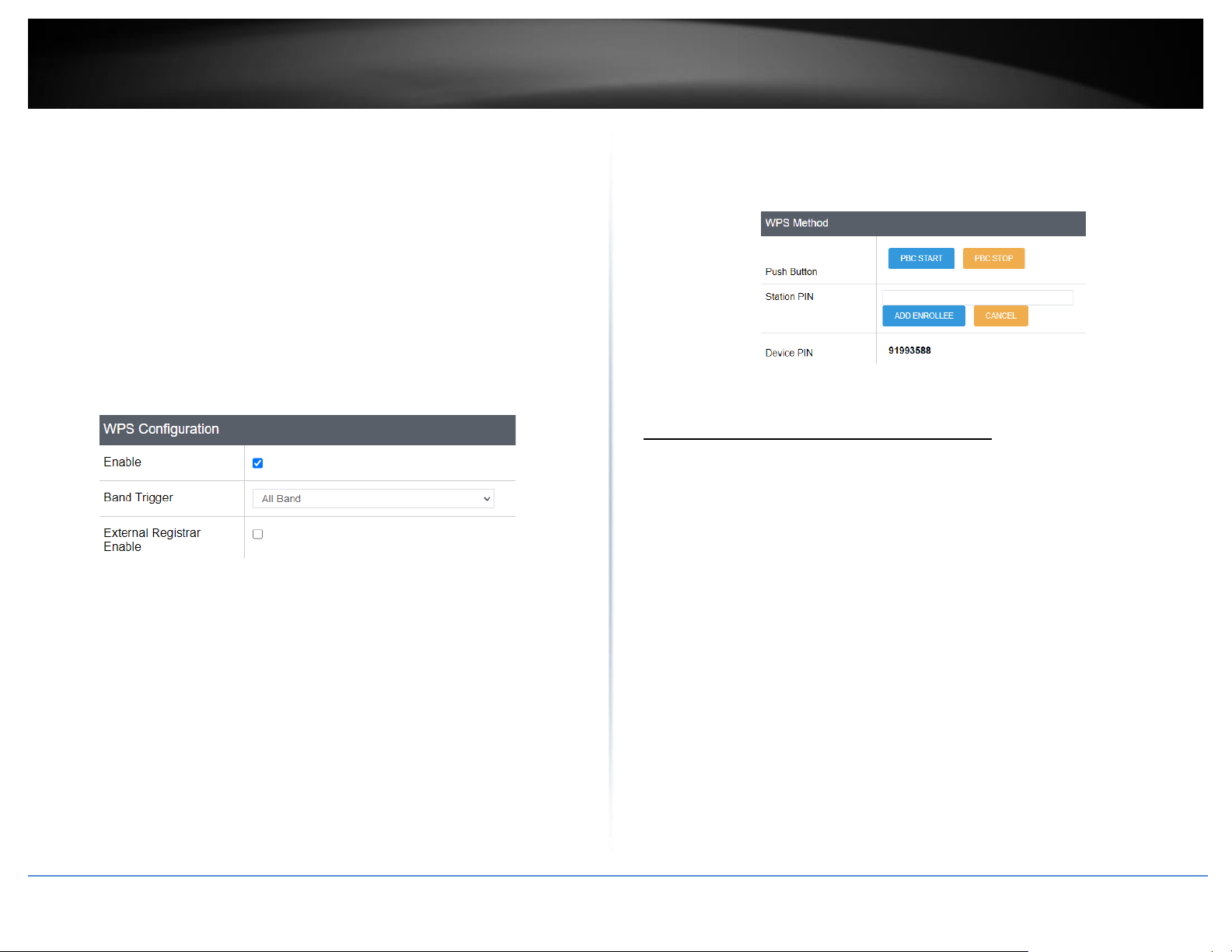
© Copyright 2023 TRENDnet. All Rights Reserved.
38
TRENDnet User’s Guide
TEW-929DRU
Below is a reference of the additional settings if you choose to make other configuration
changes to these sections. Review the settings below. When complete, click Apply to
save and commit your changes.
WPS Configuration
• Enable – Check this option to enable WPS or uncheck to disable WPS.
• Band Trigger – Click the drop-down list to select which wireless band to trigger
and activate for WPS connectivity. Select the wireless band and click Apply first
before initiating WPS connection to a wireless client device.
• External Registrar Enable – By default, the router functions in WPS registrar
mode. In WPS client connectivity, one device functions as a registrar and the
other functions as an enrollee. Checking this option will allow the router to
function enrollee mode instead of registrar mode. For security purposes, it is
recommended to leave this settings unchecked/disabled.
WPS Method
• Push Button
o PBC Start/PBC Again – Clicking this button will activate WPS.
o PBC Stop – Clicking this button will stop the WPS process.
• Station PIN – Enter the wireless client device 8 digit WPS PIN number and click
ADD ENROLLEE to activate WPS via PIN.
• Device PIN – This displays the router current WPS PIN. Wireless client devices
may have the ability to enter the PIN of the wireless router/access point you
would like to connect. Instead of entering the wireless client device PIN under
station PIN, you can enter the router device PIN in the wireless client device to
activate WPS via PIN method.
WPS Status
• Current Status – Displays the current WPS process status.
• Network Name(SSID) – Displays the current wireless network name for each
wireless band.
• Security – Displays the current security used on each wireless band.
• Status – Displays the current configuration status of WPS on the router.
Steps to improve wireless connectivity
There are a number of factors that can impact the range of wireless devices. Follow
these tips to help improve your wireless connectivity:
1. Keep the number of obstructions to a minimum. Each obstruction can reduce
the range of a wireless device. Position the wireless devices in a manner that
will minimize the amount of obstructions between them.
a. For the widest coverage area, install your router near the center of
your home, and near the ceiling, if possible.
b. Avoid placing the router on or near metal objects (such as file cabinets
and metal furniture), reflective surfaces (such as glass or mirrors), and
masonry walls.
c. Any obstruction can weaken the wireless signal (even non-metallic
objects), so the fewer obstructions between the router and the
wireless device, the better.
d. Place the router in a location away from other electronics, motors,
and fluorescent lighting.
Page 47
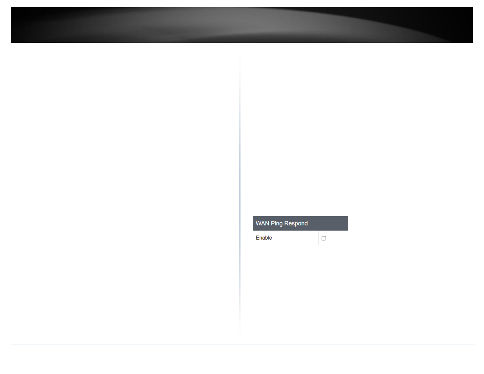
© Copyright 2023 TRENDnet. All Rights Reserved.
39
TRENDnet User’s Guide
TEW-929DRU
e. Many environmental variables can affect the router’s performance, so
if your wireless signal is weak, place the router in several locations and
test the signal strength to determine the ideal position.
2. Building materials can have a large impact on your wireless signal. In an indoor
environment, try to position the wireless devices so that the signal passes
through less dense material such as dry wall. Dense materials like metal, solid
wood, glass or even furniture may block or degrade the signal.
3. Antenna orientation can also have a large impact on your wireless signal. Use
the wireless adapter’s site survey tool to determine the best antenna
orientation for your wireless devices.
4. Interference from devices that produce RF (radio frequency) noise can also
impact your signal. Position your wireless devices away from anything that
generates RF noise, such as microwaves, radios and baby monitors.
If possible, upgrade wireless network interfaces (such as wireless cards in computers)
from older wireless standards to 802.11n, 802.11ac, or 802.11ax. If a wirelessly
networked device uses an older standard, the performance of the entire wireless
network may be slower. If you are still experiencing low or no signal consider
repositioning the wireless devices, installing additional access points or wireless
extenders.
Firewall & security settings
General settings
Security > Firewall > General Settings
1. Log into your router management page (see “Access your router management page”
on page 6).
2. Click on Network, click on Firewall, and click on the General Settings tab.
3. Review the settings below. When complete, click Apply to save and commit your
changes.
General Settings
WAN Ping Respond
• Enable – By default, this function is disabled to prevent the WAN port interfaces
from responding to ping/ICMP requests. Enabling this option will set your WAN port
interfaces to respond ping/ICMP requests from the Internet.
Page 48
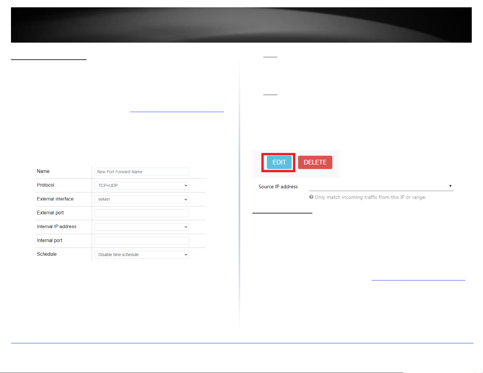
© Copyright 2023 TRENDnet. All Rights Reserved.
40
TRENDnet User’s Guide
TEW-929DRU
Port forwarding rules
Security > Firewall > Port Forward
Port forwarding rules allow to create inbound rules from the WAN interfaces/Internet to
your internal computers or devices for specific services/protocols such as a file server
(FTP), IP camera, web server (HTTP/HTTPS), or remote access, etc.
1. Log into your router management page (see “Access your router management page”
on page 6).
2. Click on Security, click on Firewall, and click on the Port Forward tab.
3. Review the settings below. When complete, click Add to add the new entry to the list
and Apply to save and commit your changes.
• Name – Enter a name for the new port forwarding rule.
• Protocol – Click the drop-down list to select the protocol for the service to allow:
TCP, UDP, TCP+UDP, or Other.
• External Interface – Click the drop-down list to select the external WAN interface(s)
to allow: WAN1, WAN2, or WAN1+WAN2. For example, choosing WAN1 will only
allow the port forward to work on inbound connection requests on WAN1 only and
inbound connections requests on WAN2 will be denied.
• External Port – Enter the external port number for the service to allow.
Note: You can also enter a consecutive range of ports in the following format: 80-90
• Internal IP address – Click the drop-down list to select a device from the list or
enter the local/internal IP address of the device to forward the port/protocol
service.
• Internal Port – Enter the internal port number for the service to allow.
Note: You can also enter a consecutive range of ports in the following format: 80-90
Typically, the internal port or port range is same as the external port or port range.
• Schedule – Allows you to select a schedule when the port forwarding rule should be
enabled or disabled.
Note: To restrict access to source IP address, after you have created the port forward
rule, click Edit on the port forwarding entry in the list and enter the IP address in Source
IP address field, then click Apply.
Port trigger rules
Security > Firewall > Port Trigger
Port triggering is typically used for applications that require a range of ports to be
dynamically opened on request to an internal device on your network. The router will
wait for a request on a specific port or range of ports (trigger port) from a device on
your network and once a request is detected by your router, the router will forward a
port or range of ports (match port) to the device on your network.
1. Log into your router management page (see “Access your router management page”
on page 6).
2. Click on Security, click on Firewall, and click on the Port Trigger tab.
3. Review the settings below. When complete, click Add to add the new entry to the list
and Apply to save and commit your changes.
Page 49
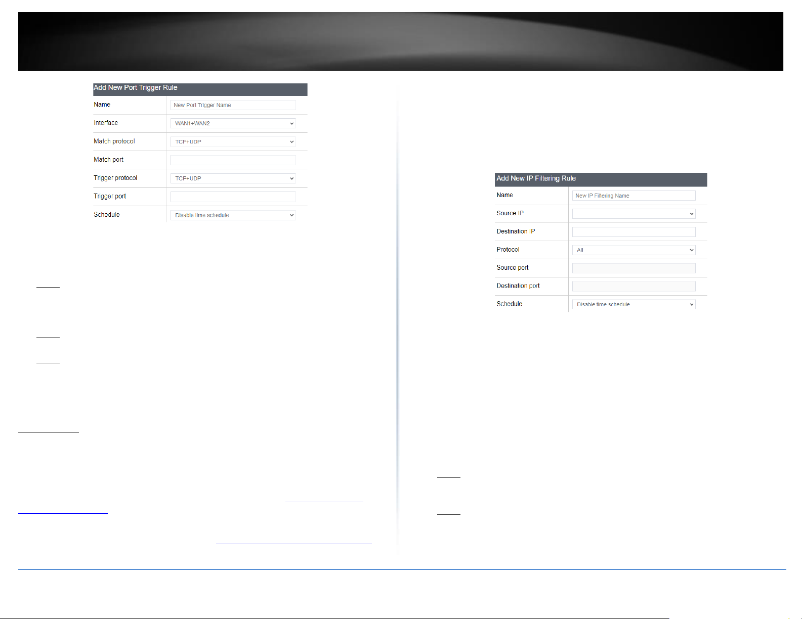
© Copyright 2023 TRENDnet. All Rights Reserved.
41
TRENDnet User’s Guide
TEW-929DRU
• Name – Enter a name for the new port trigger rule.
• Match Protocol – Click the drop-down list to select the match port protocol for the
service to allow: TCP, UDP, or TCP+UDP.
• Match Port – Enter the match port number for the service to allow.
Note: You can also enter a consecutive range of ports in the following format: 80-90
• Trigger Protocol – Click the drop-down list to select the trigger port protocol for the
service to allow: TCP, UDP, or TCP+UDP.
• Trigger Port – Enter the match port number for the service to allow.
Note: You can also enter a consecutive range of ports in the following format: 80-90
• Internal Port – Enter the internal port number for the service to allow.
Note: You can also enter a consecutive range of ports in the following format: 80-90
Typically, the internal port or port range is same as the external port or port range.
• Schedule – Allows you to select a schedule when the port trigger rule should be
enabled or disabled.
IP filtering
Security > Firewall > IP Filtering
IP filtering allows you to restrict access to the Internet to specific IP addresses on your
network. You can check the current IP addresses assigned to devices connected to your
router under Status > Overview under the DHCP leases section. You can also lock the IP
address assigned to specific devices connected to your router by adding static DHCP
leases or reservations.
1. Log into your router management page (see “Access your router management page”
on page 6).
2. Click on Security, click on Firewall, and click on the IP Filtering tab.
3. Review the settings below. When complete, click Add to add the new entry to the list
and Apply to save and commit your changes.
• Name – Enter a name for the new IP filtering rule.
• Source IP – This is the source IP address or device IP address to filter. Click the drop-
down list to select a device from the list or enter the local/internal IP address of the
device to filter or restrict.
• Destination IP – This is the destination IP address for the IP filtering rule. Since the
IP filtering rule only applies to outbound Internet access, this will need to be a
public Internet IP. You can leave this setting blank to set the rule to apply to any
public Internet IP address.
• Protocol – Click the drop-down list to select the protocol for the service to restrict:
All, TCP, UDP, TCP+UDP, or ICMP.
• Source Port – This is the source port number. Enter the source port number for the
service to restrict.
Note: You can also enter a consecutive range of ports in the following format: 80-90
• Destination Port – This is the destination port number. Enter the destination port
number for the service to restrict.
Note: You can also enter a consecutive range of ports in the following format: 80-90
• Schedule – Allows you to select a schedule when the IP filter rule should be enabled
or disabled.
Page 50
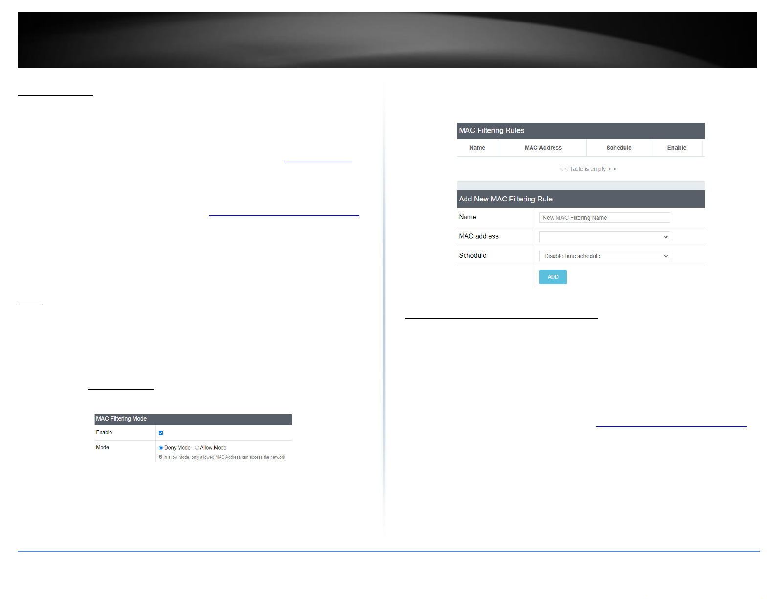
© Copyright 2023 TRENDnet. All Rights Reserved.
42
TRENDnet User’s Guide
TEW-929DRU
MAC filtering
Security > Firewall > MAC Filtering
Every network device has a unique, 12-digit MAC (Media Access Control) address. MAC
filtering allows you to restrict access to the Internet to specific MAC addresses on your
network. MAC filtering in this section applies to both wired and wireless devices. To
create MAC filtering rules on your wireless network only, go to the Wireless Settings
section under MAC-filter. You can check the current MAC addresses of devices
connected to your router under Status > Overview under the DHCP leases section.
1. Log into your router management page (see “Access your router management page”
on page 6).
2. Click on Security, click on Firewall, and click on the MAC Filtering tab.
3. Check the Enable option to enable MAC filtering and select Mode.
Note: Please make sure to add the MAC addresses in the list first before clicking Apply.
• Enable – Check this option to enable MAC filtering.
• Mode – Select the mode used for MAC filtering.
o Deny Mode (Blacklist) – Sets the MAC filter action to deny only the
MAC addresses listed and allow all others access to the Internet.
o Allow Mode (Whitelist) – Sets the MAC filter action to allow only the
MAC address listed and deny all others access to the Internet.
Important Note: Please make sure to add the MAC addresses in this
list before applying the setting especially in Allow mode.
4. Review the settings below. When complete, click Add to add the new entry to the list
and Apply to save and commit your changes.
• Name – Enter the name for the MAC filter rule.
• MAC Address – Click the drop-down list to select a device from the list or enter
the MAC address manually. (e.g. a1:b2:c3:d4:e5:f6)
• Schedule – Allows you to select a schedule when the MAC filter rule should be
enabled or disabled.
Denial of service (DoS) prevention
Security > Firewall > DoS Prevention
The router supports prevention against common denial of service (DoS) attacks.
Malicious users use denial of service attacks to temporarily or permanently disrupt the
availability of services from network resource such as your router. Typically, DoS attacks
are achieved by flooding a specific network resource by excessively sending unnecessary
requests which can cause the network device or resource to stop functioning.
1. Log into your router management page (see “Access your router management page”
on page 6).
2. Click on Network, click on Firewall, and click on the DoS Prevention tab.
3. Review the settings below. When complete, Apply to save and commit your changes.
Choose the DoS prevention type to enable, TCP SYN flood, UDP flood, or ICMP flood.
• Enable – Check this option to enable DoS prevention.
Page 51
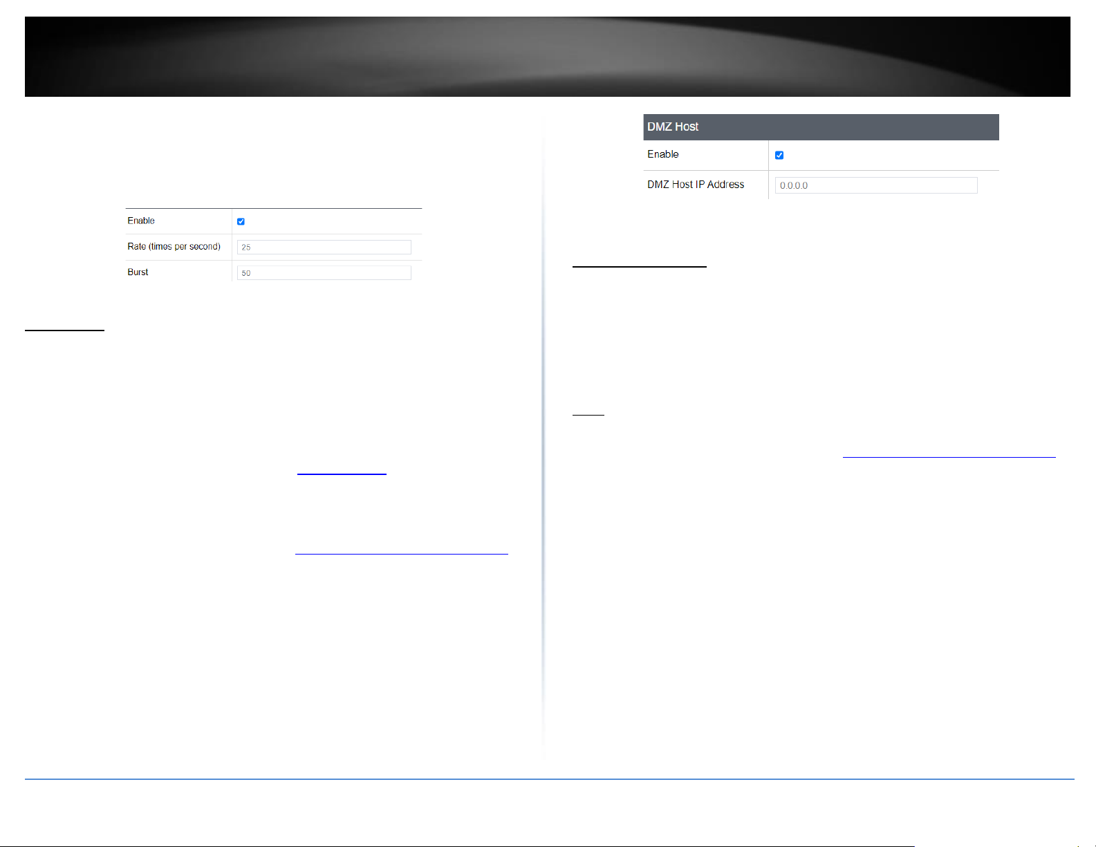
© Copyright 2023 TRENDnet. All Rights Reserved.
43
TRENDnet User’s Guide
TEW-929DRU
• Rate (times per second) – This value limits the amount of packets that can be
received by the router per second for a specific session.
• Burst – This value limits the total amount of packets that can be received and
stored in buffer memory for a specific session.
DMZ Host
Security > Firewall > DMZ Host
You may want to expose a specific computer or device on your network to the Internet
to allow anyone to access it. Your router includes the DMZ (Demilitarized Zone) feature
that makes all the ports and services available on the WAN/Internet side of the router
and forwards all ports to a single IP address (computer or network device) on your
network. The DMZ feature is an easy way of allowing access from the Internet however,
it is a very insecure method and will open your local area network to greater threats
from Internet attacks. It is recommended to use port forwarding instead to limit rules to
specific ports/services only.
1. Log into your router management page (see “Access your router management page”
on page 6).
2. Click on Network, click on Firewall, and click on the DMZ Host tab.
3. Review the settings below. When complete, Apply to save and commit your changes.
• Enable – Check this option to enable DMZ host.
• DMZ Host IP Address - Enter the IP address you assigned to the computer or
network device to expose to the Internet. (e.g. 192.168.10.250)
One-to-One NAT
Network > Firewall > One-to-One NAT
If you have multiple static public WAN/Internet IP addresses assigned by your ISP, you
can map the additional public IP addresses to a local computer or device on your
network and allow all or specific ports or services similar to port forwarding but using
different public IP addresses through your router. Please check with your ISP if you have
multiple static public IP addresses available that can be used to map to devices on your
local network.
Note: This feature will only work when using a static IP address WAN type/protocol.
1. Log into your router management page (see “Access your router management page”
on page 6).
2. Click on Security, click on Firewall, and click on the One-to-One NAT tab.
3. Review the settings below. When complete, click Add to add the new entry to the list
and Apply to save and commit your changes.
Page 52
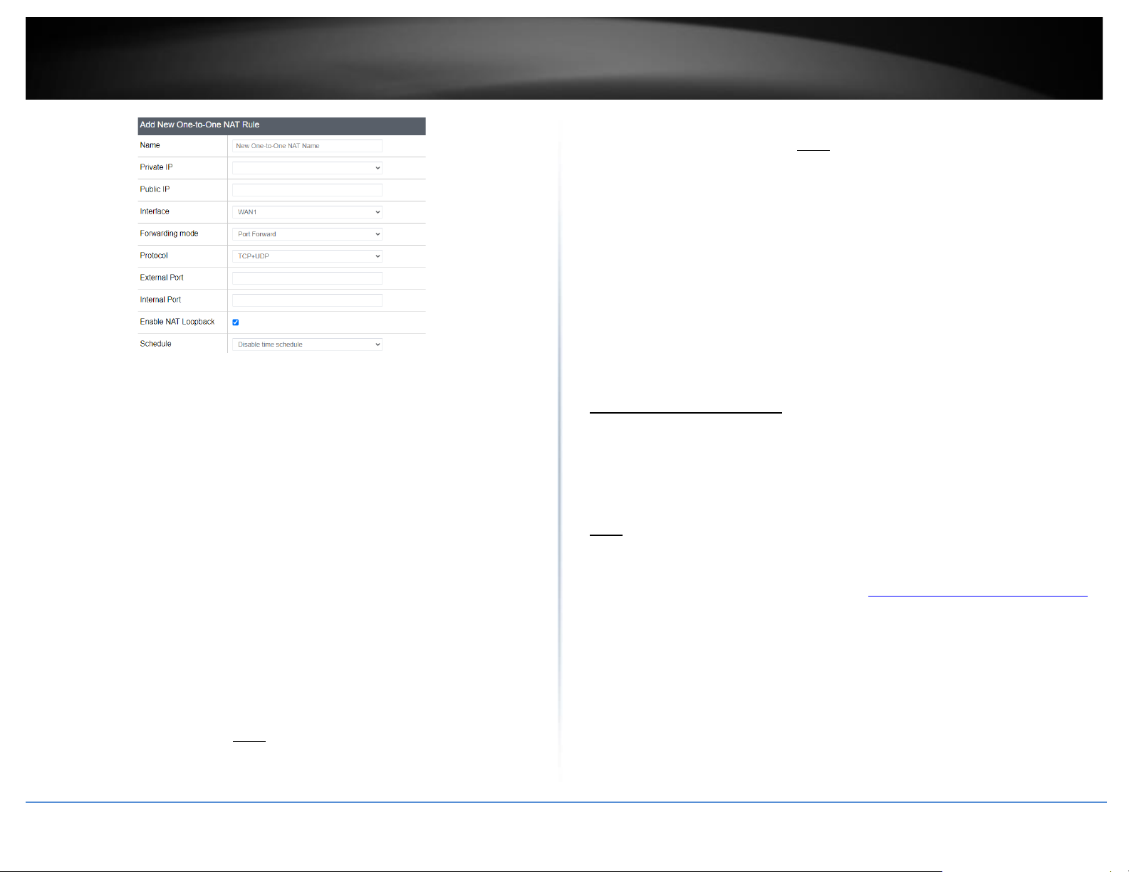
© Copyright 2023 TRENDnet. All Rights Reserved.
44
TRENDnet User’s Guide
TEW-929DRU
• Name – Enter a name for the new one-to-one NAT rule.
• Private IP address – Click the drop-down list to select a device from the list or enter
the local/internal IP address of the device to forward the port/protocol service.
• Public IP – Enter the additional static public Internet IP address you would like to
map to the local/internal IP address.
• Interface – Click the drop-down list to select the external WAN interface(s) to allow:
WAN1 or WAN2. For example, choosing WAN1 will only allow the port forward to
work on inbound connection requests on WAN1 only and inbound connections
requests on WAN2 will be denied.
• Forwarding Mode - Select DMZ to forward all ports/protocols or Port Forwarding
to specify which ports/protocols to allow.
o DMZ – Selecting this option will set the rule to forward all
ports/protocols to the device internal private IP address.
▪ Schedule – Allows you to select a schedule when the port
forwarding rule should be enabled or disabled.
o Port Forward – Selecting this option will allow to set the specific
ports/protocols to allow for the rule.
▪ Protocol – Click the drop-down list to select the protocol for
the service to allow: TCP, UDP, TCP+UDP, ICMP, or Custom.
▪ External Port – Enter the external port number for the service
to allow. Note: You can also enter a consecutive range of
ports in the following format: 80-90
▪ Internal Port – Enter the internal port number for the service
to allow. Note: You can also enter a consecutive range of
ports in the following format: 80-90
Typically, the internal port or port range is same as the
external port or port range.
▪ Enable NAT Loopback – Checking this option will allow
devices to resolve the additional public static IP addresses
from the local interfaces (e.g. LAN, VLAN). Unchecking this
option will not allow to devices to resolve the additional
public static IP addresses from the local interfaces. (e.g. LAN,
VLAN)
▪ Schedule – Allows you to select a schedule when the port
forwarding rule should be enabled or disabled.
RADIUS Authentication
Security > Administrator > RADIUS
For additional security, the RADIUS authentication feature will allow you use an external
RADIUS server to access the router management configuration page instead of using the
internal administrator user account.
Note: This feature requires an external RADIUS authentication server to be set up and
configured prior to enabling the feature on your router.
1. Log into your router management page (see “Access your router management page”
on page 6).
2. Click on Security and click on RADIUS.
3. Review the settings below. When complete, click Apply to save and commit your
changes.
• Enabled – Check this option to enable RADIUS authentication.
• Server IP Address – Enter the IP address of the external RADIUS server.
Page 53
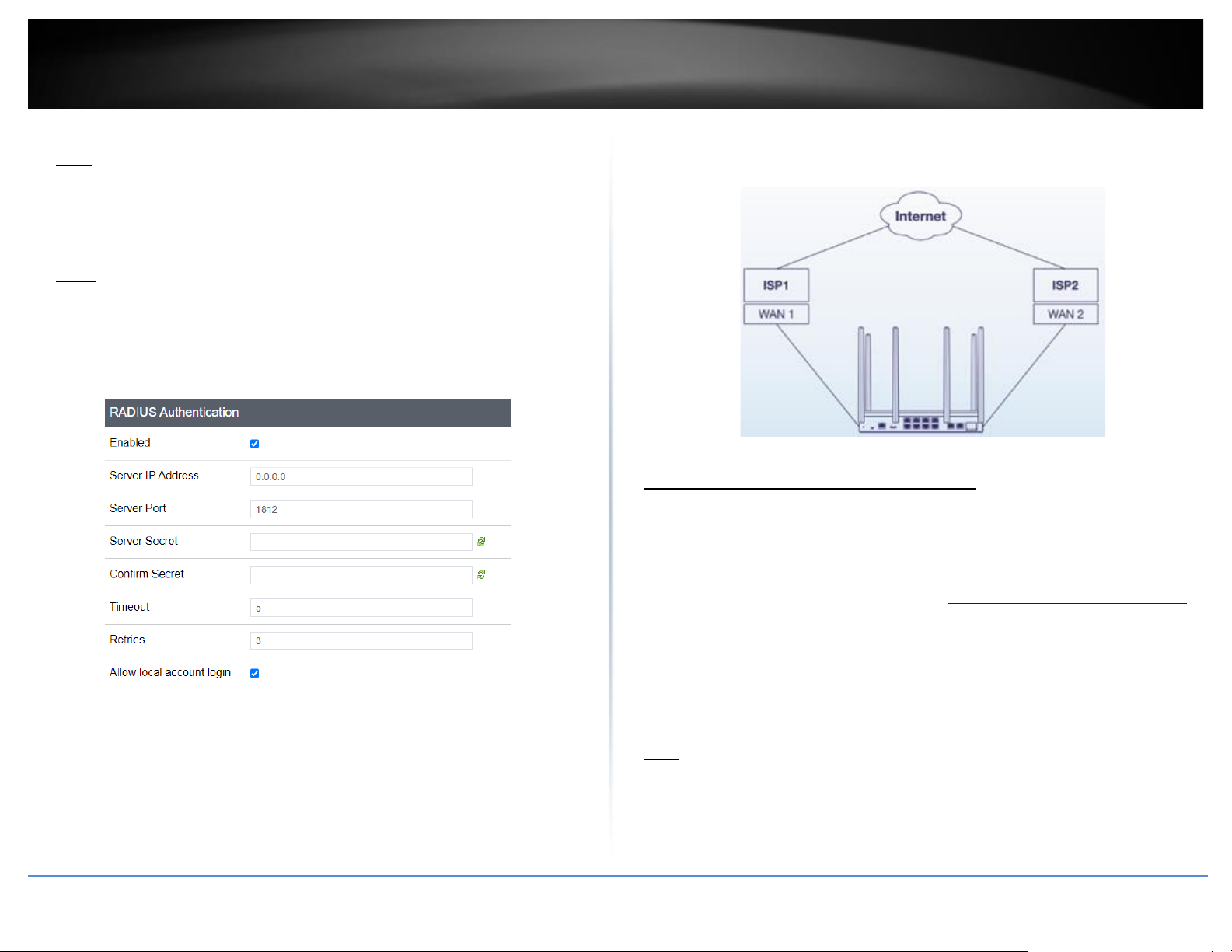
© Copyright 2023 TRENDnet. All Rights Reserved.
45
TRENDnet User’s Guide
TEW-929DRU
• Server Port – Enter the port used for the RADIUS service.
Note: The default port used for RADIUS server authentication is 1812.
• Server Secret – Enter the shared secret used to authorize the router for use with
the external RADIUS server.
• Confirm Secret – Re-enter the shared secret for confirmation.
• Timeout – Enter the RADIUS server authentication timeout value in seconds. This is
the number of seconds between transmissions for authentication requests.
Note: If you encounter issues with repeated authentication attempts, it is
recommended to increase this value.
• Retries – Enter the number of retries allowed before RADIUS server will deny
authentication requests for a specific user.
• Allow local account login – Checking this option will still allow login to the router
configuration page using the internal administrator account.
Multiple WAN Configuration
Multiple WAN Management Settings
Multi-WAN / QoS > Multiple WAN
The section provides an overview of the multiple WAN management settings and the
dual WAN mode functionality.
1. Log into your router management page (see “Access your router management page”
on page 6).
2. Click on Multi-WAN / QoS and click on Multiple WAN.
3. Review the settings below. When complete, click Apply to save and commit your
changes.
Note: Multiple WAN diagnostics can be used under Administrator > Diagnostics under
the MWAN Interface Diagnostics section.
Page 54
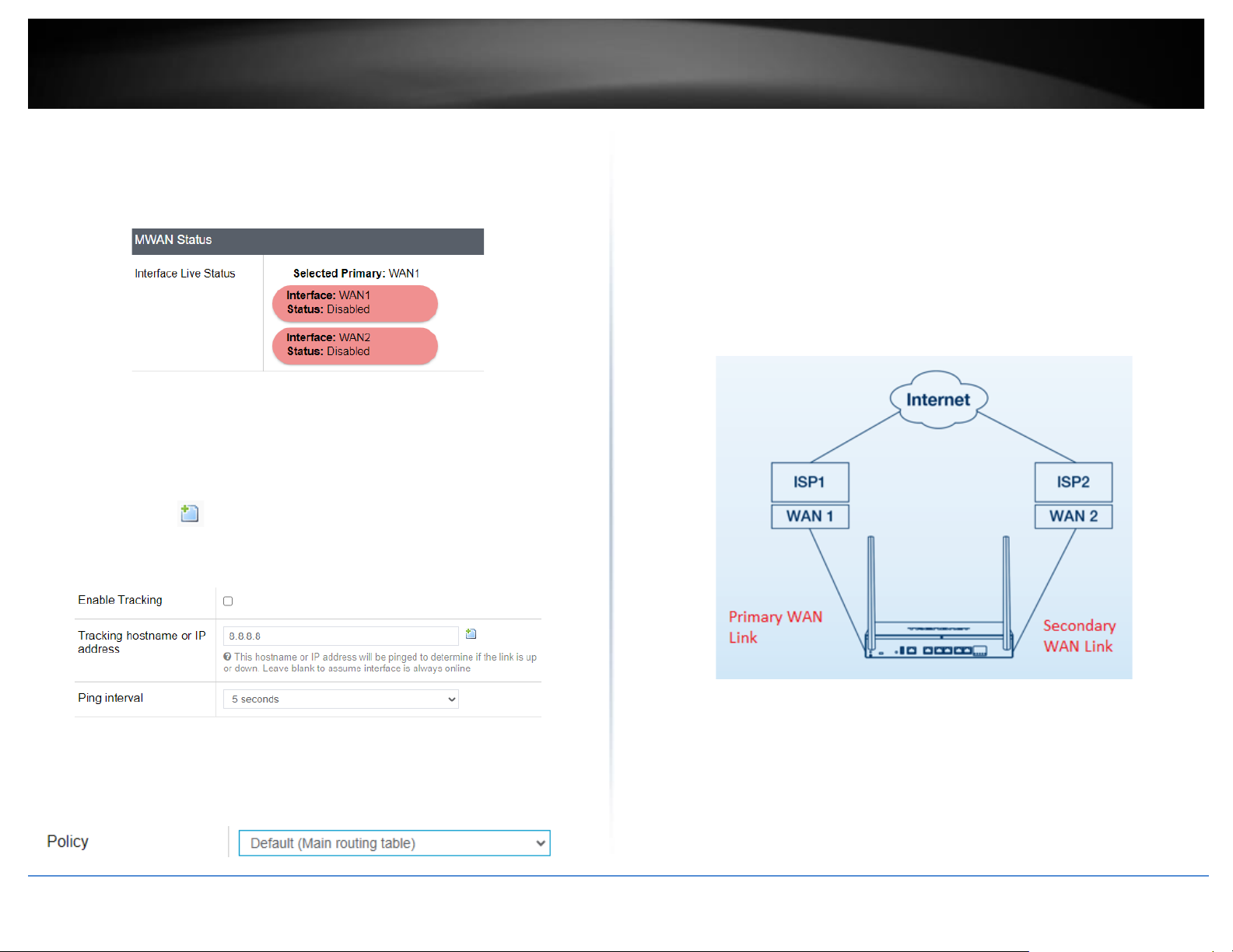
© Copyright 2023 TRENDnet. All Rights Reserved.
46
TRENDnet User’s Guide
TEW-929DRU
MWAN Status
• Interface Live Status – This section displays the current status of the WAN
interfaces of your router. Tracking is enabled using physical link status and L2 based
methods but the tracking status displayed refers to the status of IP based link
tracking which can be configured under the Link Tracking section.
Link Tracking – Allows you to setup WAN link tracking by pinging Internet IP addresses.
• Enable Tracking – Checking this option enables IP based WAN link tracking on the
specific WAN interface.
• Tracking hostname or IP – Enter an Internet IP address to send ping requests used
to verify the link status of a specific WAN interface. You can add additional IP
address by clicking .
• Ping Interval – Click the drop-down list to set the time interval between
consecutive ping requests.
Default Traffic Rule
• Policy – This setting controls the default WAN mode for Internet connectivity access
for all local interface such as LAN, wireless LAN, and VLAN interfaces.
o WAN1 (Failover to WAN2) – This is the default WAN mode. In this
mode, the primary WAN interface is set to WAN1 and secondary WAN
interface is set to WAN2. All traffic will be routed only through WAN1
and will only route to WAN2 for Internet connectivity if the WAN1
primary interface link status fails. If WAN1 connectivity is restored, all
Internet traffic will revert back to the primary WAN1 interface.
o WAN2 (Failover to WAN1) –In this mode, the primary WAN interface
is set to WAN2 and secondary WAN interface is set to WAN1. All traffic
will be routed only through WAN2 and will only route to WAN1 if the
WAN2 primary fails or is disconnected. If WAN2 connectivity is
restored, all Internet traffic will revert back to the primary WAN2
interface.
o WAN1 (Fixed) – In this mode, all Internet traffic will only be routed to
the WAN1 interface. The WAN2 interface is not used.
o WAN2 (Fixed) – In this mode, all Internet traffic will only be routed to
the WAN2 interface. The WAN1 interface is not used.
Page 55
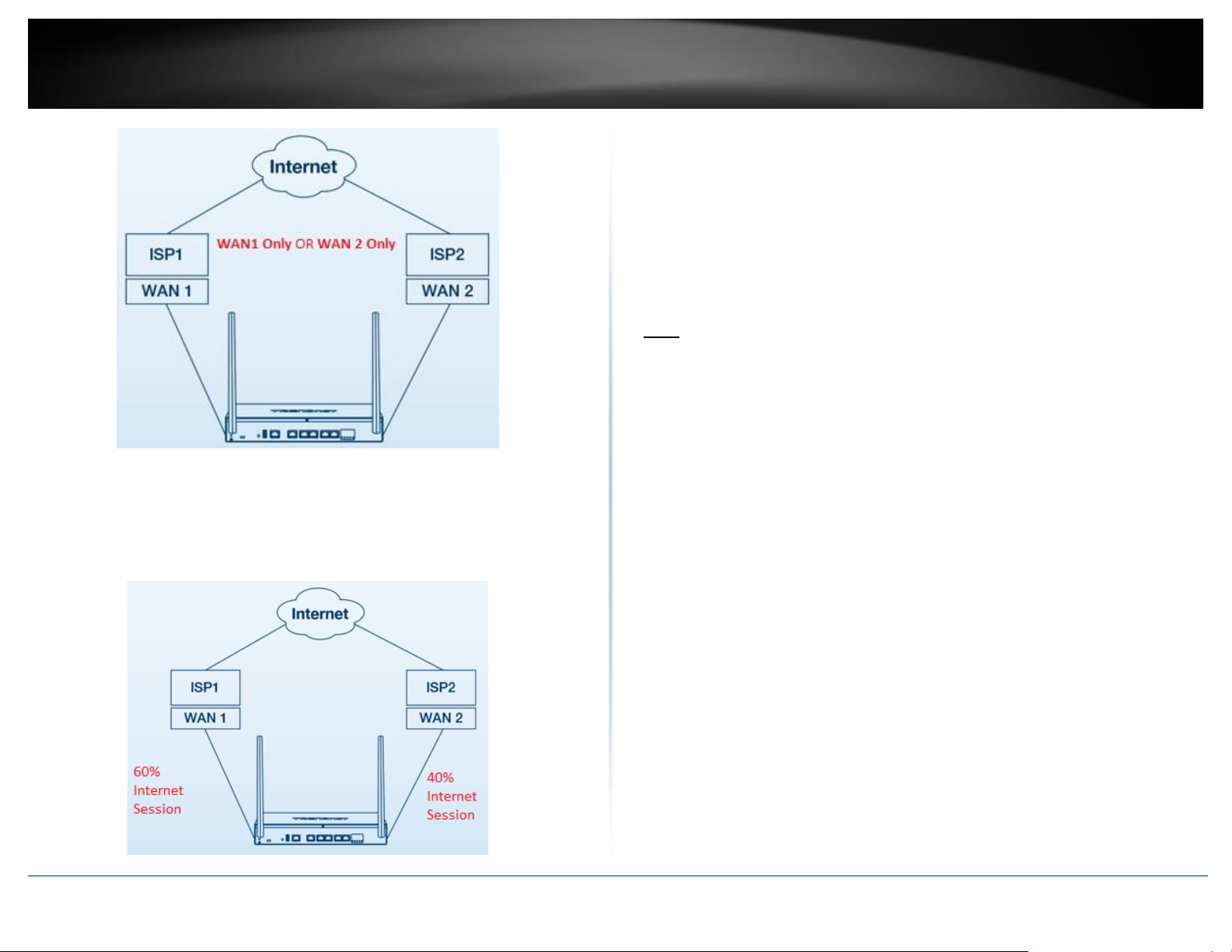
© Copyright 2023 TRENDnet. All Rights Reserved.
47
TRENDnet User’s Guide
TEW-929DRU
o Load Balance – In this mode, Internet traffic will be routed to both
WAN1 and WAN2 interfaces based on weighted percentage. Traffic
will be distributed to WAN1 and WAN2 based on the total of sessions
and weighted % assignment. For example: If selecting a weight of 60%
: 40% (WAN1:WAN2), 60% of all Internet sessions will be sent to
WAN1 and the remaining 40% will be sent to WAN2.
o Default (Use main routing table) – Selecting this option will use the
internal routing table to make routing decisions between WAN1 and
WAN2 and allow you to device custom policies under the Advanced
tab.
Web Management System (Bark®)
Bark web management system allows you to easily setup and monitor the content
accessed by devices on your network to maximize Internet bandwidth usage, control,
and productivity.
Note: Please make sure to set your router date and time settings correctly to ensure
proper functionality of the Bark feature. Subscription based web management filtering
content services are available with account sign up. Additional upgrades may be
available with an additional cost. Services may be subject to change without notice.
Page 56
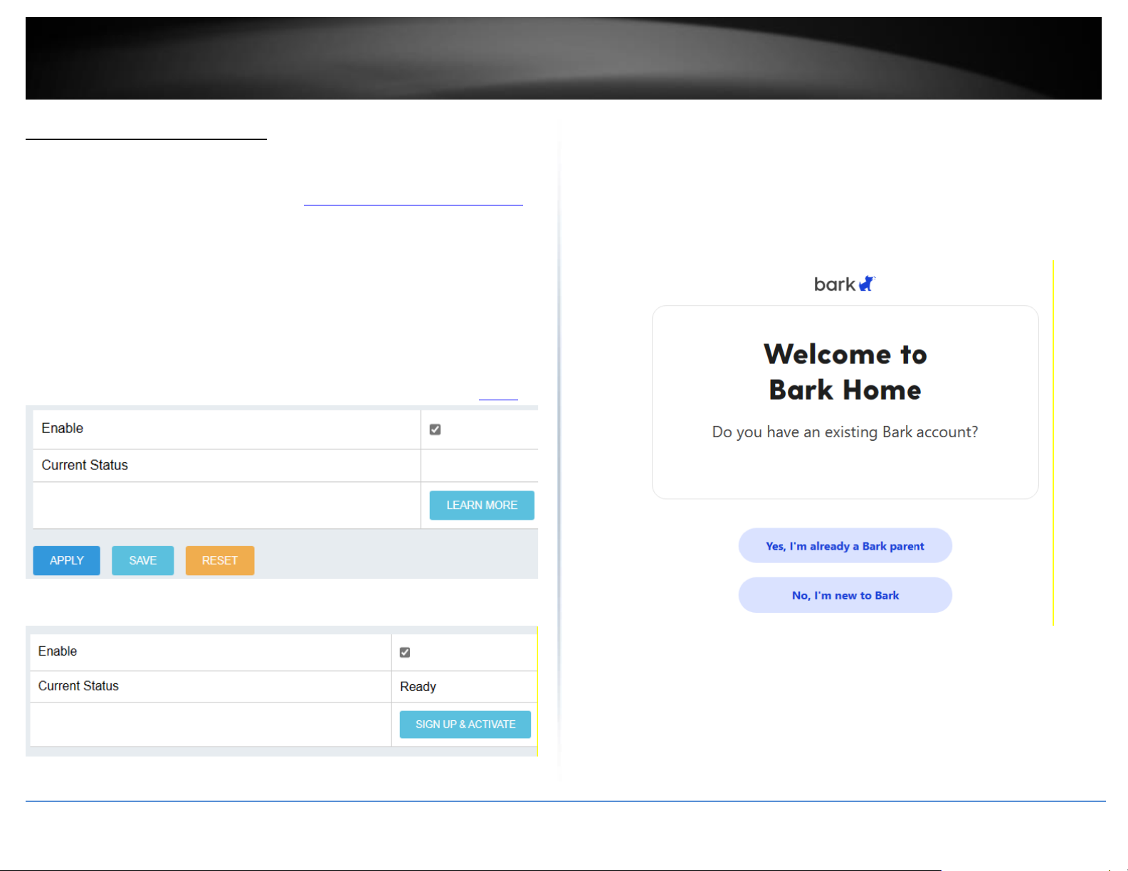
© Copyright 2023 TRENDnet. All Rights Reserved.
48
TRENDnet User’s Guide
TEW-929DRU
Setup your router with Bark®
System > Bark
1. Log into your router management page (see “Access your router management page”
on page 6).
2. Click on System and click on Bark®.
3. Check the Enable option and click Apply.
Note: You may be prompted to make sure your router date and time configuration
settings are configured correctly. Please make sure manually configure the router date
and time settings or synchronize date and time with an NTP server. It is important to
make sure the router date and time settings are configured correctly before enabling
and configuring Bark®. To configure the router date and time settings, refer to page 7.
4. After enabling the Bark® service, click Sign Up & Activate.
4. At the signup page, to create a new Bark® account, click No, I’m new to Bark.
Note: If you had previously created an account with Bark®, click Yes, I’m already a Bark
parent and you will be prompted to login and continue with the steps to add your router
to your Bark account.
5. Click Get Started and continue with the steps following to create your Bark account.
Page 57
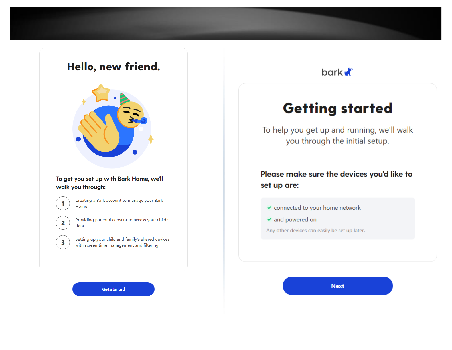
© Copyright 2023 TRENDnet. All Rights Reserved.
49
TRENDnet User’s Guide
TEW-929DRU
6. After your have successfully created your Bark account, click Next to add your router
device to your Bark account.
Page 58
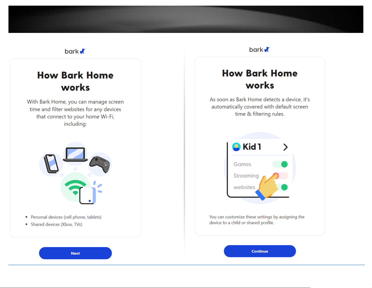
© Copyright 2023 TRENDnet. All Rights Reserved.
50
TRENDnet User’s Guide
TEW-929DRU
7. On the next page, click Next.
8. On the next page, click Continue.
Page 59
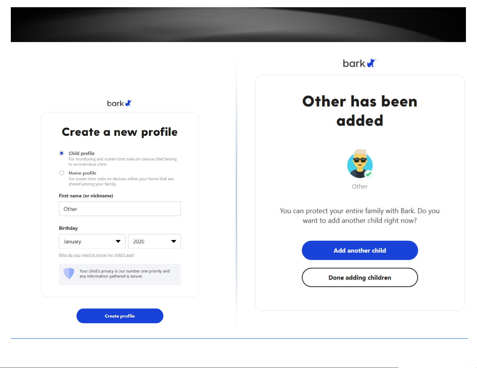
© Copyright 2023 TRENDnet. All Rights Reserved.
51
TRENDnet User’s Guide
TEW-929DRU
9. To get started, create a new Child Profile and enter the name Other. Select any date
for the Birthday.
Note: Bark works by assigning specific devices to created profiles in which each profile
can be assigned a specific set of access rules. If you are using the router on a home
network, you can create a Bark profile named Children or Kids and apply the specific
devices and rules later on.
10. Click Done Adding Children.
Page 60
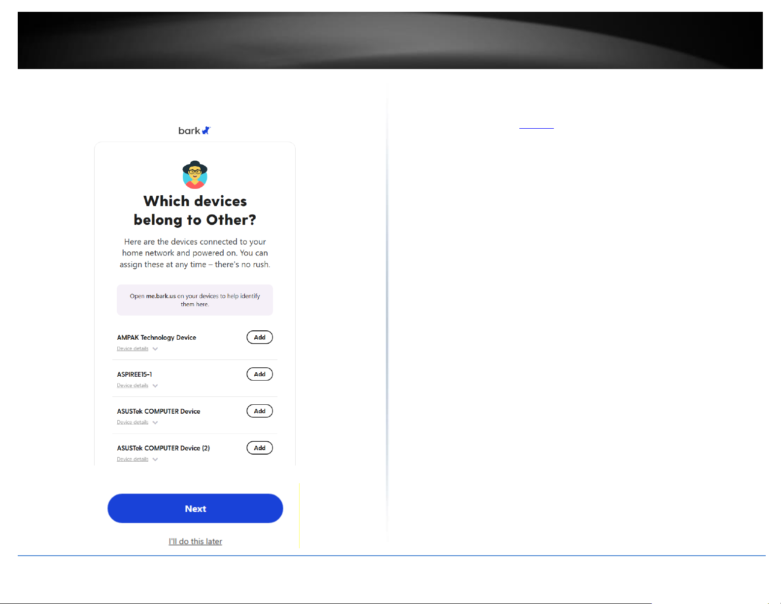
© Copyright 2023 TRENDnet. All Rights Reserved.
52
TRENDnet User’s Guide
TEW-929DRU
11. A list of devices connected and discovered by your router will be listed prompted if
you would like to assign these devices to the new profile “Other”. If you would like to do
this later, scroll to the bottom of the page and click Next or I’ll do this later.
12. On the Dashboard page, scroll down and under the Bark Home section, you will find
that the TRENDnet TEW-929DRU router has been added to your Bark account. For
additional information regarding Bark functionality and configuration, please refer to
the Bark website under the Discover section for details.
Page 61
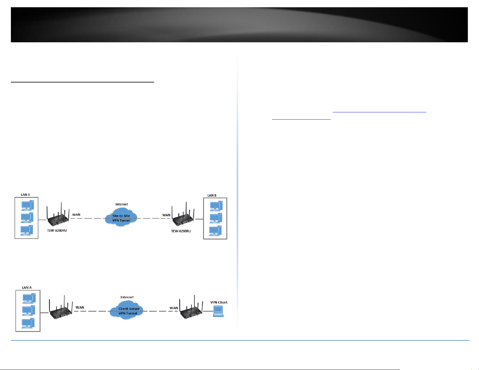
© Copyright 2023 TRENDnet. All Rights Reserved.
53
TRENDnet User’s Guide
TEW-929DRU
Virtual Private Networking (VPN)
Creating a Virtual Private Network (VPN)
Network > VPN
What is a VPN?
A VPN provides secure communications typically over the Internet by creating a secure
tunnel between two or more VPN routers (gateways) also known as a site-to-site VPN or
between a single client computer and a VPN router (gateway) also known as a clientserver VPN.
On your router, the following types of tunnels can be created:
• Site-to-Site VPN – Connects two or more VPN routers (gateways) allowing the
LAN network from each router to securely communicate to each other over the
Internet. Tunneling Methods: IPsec
• Client-Server VPN – A single client computer or device with VPN client software
installed connects to a VPN router (gateway) allow the single client computer
or device to securely communicate to the LAN network of the VPN router over
the Internet. Tunneling Methods: IPsec/SSL(OpenVPN)/PPTP/L2TP/L2TP with
IPsec
Tunneling methods supported by your router:
• SSL (Secure Socket Layer) VPN – This type of VPN can be used for Client-Server
VPN only. There is support for both Layer 3 and Layer 7 network access with
SSL VPN but your router only supports Layer 3 access. Additionally, your router
utilizes the use of OpenVPN® for SSL VPN. The third party software client is
available for free download using the following link for both Windows® and
Linux operating systems https://openvpn.net/index.php/open-
source/downloads.html.
• IPsec (Internet Protocol Security) VPN – This type of VPN can be used for
either Site-to-Site VPN or Client-Server VPN, however, the most common
application for this type is a Site-to-Site VPN. This type of VPN can provide
highest degree of security. For a Client-Server VPN, typically, a third party VPN
client software is required to be installed and configured and can be difficult
when installing and configuring on VPN client computers. This VPN type can
provide the highest degree of security.
• PPTP (Point-to-Point Tunneling Protocol) VPN – This type of VPN can be used
for Client-Server VPN only however both server mode and client mode are
supported on your router. Most computer operating systems already include a
pre-installed PPTP VPN client software that can be easily configured which
eliminates the need for an additional third party VPN client software to be
purchased and installed. Since it provides less security overall than IPsec VPN, it
is not recommended for a Site-to-Site VPN.
• L2TP (Layer 2 Tunneling Protocol) VPN – This type of VPN is very similar to
PPTP VPN as it is most commonly used for a Client-Server VPN, pre-installed on
most computer operating systems and easy to configure, and provides less
overall security than IPsec VPN. Most of the current operating systems with
L2TP VPN client software pre-installed use L2TP VPN in conjunction with IPsec
VPN to improve the overall security provided. This router does not support the
L2TP over IPsec VPN method.
Important Note: For any tunneling or VPN method used, to avoid IP address conflict and
to ensure connectivity, it is required that each end (LAN IP network or single client) of the
VPN tunnel is configured with a different IP network or subnet.
Page 62
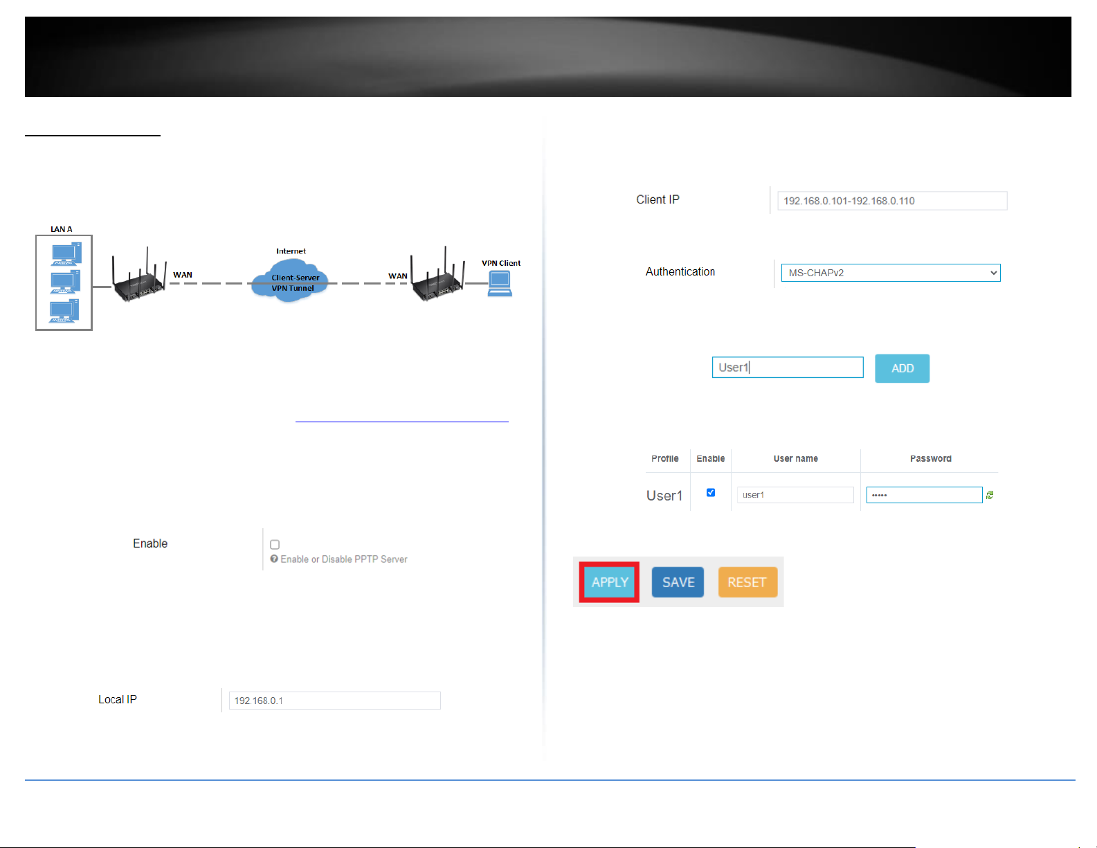
© Copyright 2023 TRENDnet. All Rights Reserved.
54
TRENDnet User’s Guide
TEW-929DRU
PPTP VPN Server
Security > VPN > PPTP Server
You can enable and configure the PPTP VPN server on your router to allow remote
computers or mobile devices with PPTP VPN support to connect securely over the
Internet and access the company LAN network.
Setting up the PPTP VPN server
1. Log into your router management page (see “Access your router management page”
on page 6).
2. Click on Security, click VPN, and click the PPTP Server tab.
3. Under Service Setting, check the Enable option to enable the PPTP server.
4. In the Local IP field, enter the LAN IP address. (Default LAN IP: 192.168.10.1)
Note: Entering the LAN IP address as the Local IP of the PPTP server ensures your PPTP
VPN clients are able to access the Internet and the router LAN network via full tunneling.
If an IP address different from the LAN IP is entered, PPTP VPN clients will be allowed to
access router LAN and not the Internet.
5. In the Client IP field, enter an IP address range (within the same LAN IP subnet range)
to assign to PPTP VPN clients. By default, the router LAN DHCP server pool is
192.168.10.101-192.168.10.199, therefore, we will assign a range that does not conflict
with the DHCP server range such as 192.168.10.10-192.168.10.20.
6. Click the Authentication drop-down list and select MS-CHAPv2.
7. Under the User Account section, enter a profile name for the new user account and
click Add. (e.g. User1)
8. Check the Enable option and enter a User name and Password for the new user
account. (e.g. User name: user1 / Password: user1)
9. Click Apply and the bottom of the page so save and commit the changes.
10. Click on the Status > Overview page and under the Network section, make note of
your WAN IPv4 addresses to configure the PPTP VPN clients. You can also configure
dynamic DNS to use a dynamic DNS hostname instead of dynamic WAN IP address.
Note: For the VPN client computer, you will require a third party PPTP VPN software to
be installed configured matching the PPTP VPN settings on your router. Typically, PPTP
VPN software is pre-installed with most operating systems. Please refer to your
Page 63
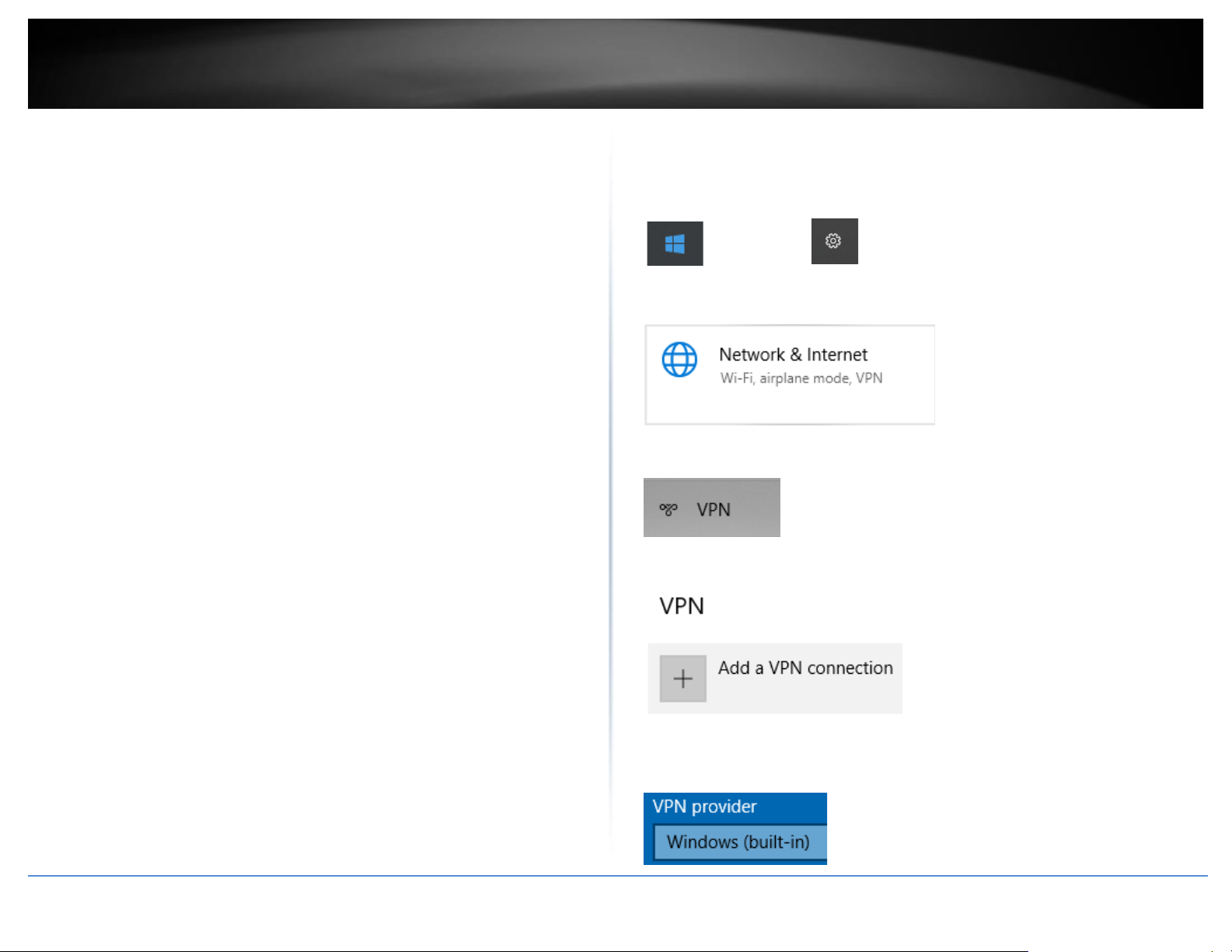
© Copyright 2023 TRENDnet. All Rights Reserved.
55
TRENDnet User’s Guide
TEW-929DRU
operating system or mobile device User’s Guide/Manual for configuring the VPN
settings.
Below is a reference of the additional PPTP VPN server settings if you choose to make
other configuration changes to these sections.
• Enable – Check this option to enable the PPTP VPN server.
• Local IP – Enter an IP address for the PPTP VPN server. This should be the same
as your LAN IPv4 address to allow both access to LAN network and Internet to
VPN clients via full tunneling. (e.g. 192.168.10.1)
• Client IP – Enter the IP address pool to distribute to your PPTP VPN clients after
they establish VPN connectivity. This should be in the same IPv4 subnet used as
your Local IP address. If using the same as the router LAN IP address, make sure
to assign a range different from your LAN DHCP server IP range. (e.g.
192.168.10.10-192.168.10.20)
• MS-DNS 1 – Enter the IPv4 address of the primary DNS server to distribute to
PPTP VPN clients after they establish VPN connectivity. This parameter is
optional. (e.g. 8.8.8.8)
• MS-DNS 2 – Enter the IPv4 address of the secondary DNS server to distribute to
PPTP VPN clients after they establish VPN connectivity. This parameter is
optional. (e.g. 8.8.4.4)
• MS-WINS 1 – Enter the IPv4 address of the primary WINS server to distribute to
PPTP VPN clients after they establish VPN connectivity. This parameter is
optional. (e.g. 192.168.10.32)
• MS-WINS 2 – Enter the IPv4 address of the secondary WINS server to distribute
to PPTP VPN clients after they establish VPN connectivity. This parameter is
optional. (e.g. 192.168.10.33)
• Authentication – Click the drop-down list and select the authentication
protocol to use for PPTP VPN authentication, PAP/CHAP/MS-CHAPv1/MS-
CHAPv2. It is strongly recommended to use MS-CHAPv2 since it offers the
highest degree of security from these options and is supported by most
modern computers and mobile devices.
Setting up the PPTP VPN client (Windows)
Note: This procedure provides a basic example how to setup PPTP VPN and establish
connectivity using a Windows® 10 client computer. If you are using a different operating
system or mobile device, please refer to the user’s guide/manual of the third party
operating system or device on configuring PPTP VPN. The PPTP VPN settings must match
with the settings configured on the router.
1. Click the Start button and click the Settings icon.
Start Button Settings icon
2. Click Network & Internet.
3. Click VPN in the left panel.
4. Under VPN, click Add a VPN connection.
5. Click the VPN provider drop-down list and select Windows (built-in).
Page 64
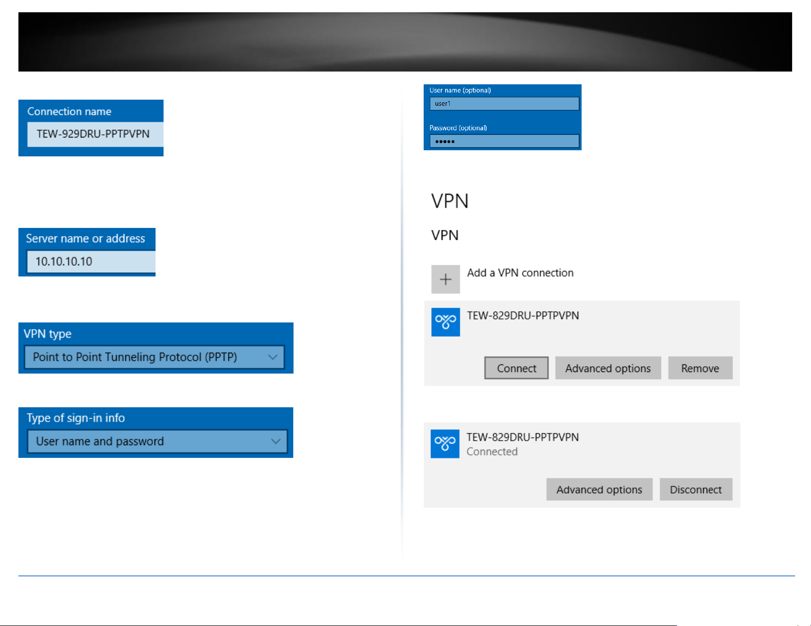
© Copyright 2023 TRENDnet. All Rights Reserved.
56
TRENDnet User’s Guide
TEW-929DRU
6. Enter a name in the Connection name field.
7. Enter the Internet WAN IP address, DNS, or dynamic DNS hostname of your router to
connect over the Internet. In the example below, the Internet WAN IP address of the
router is 10.10.10.10. In your router, you can check the WAN IP address under Status
> Overview, under Network in the IPv4 status section.
8. Click the VPN type drop-down list and select Point to Point Tunneling Protocol
(PPTP).
9. Click the Type of sign-in info drop-down list and select User name and password.
10. You can choose to enter the account credentials in the fields provide for
authentication or if not, you will be prompted when attempting to establish PPTP VPN
connection to your TEW-829DRU router. Click Save.
11. Under VPN, the new VPN connection will be listed. Click Connect.
12. The status will display Connected if the PPTP VPN connection was successful.
Page 65
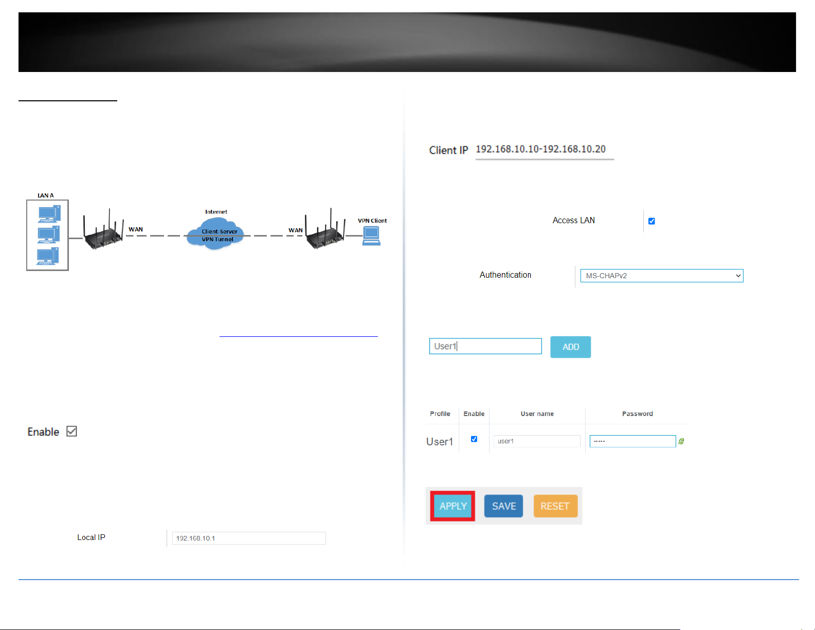
© Copyright 2023 TRENDnet. All Rights Reserved.
57
TRENDnet User’s Guide
TEW-929DRU
L2TP VPN Server
Security > VPN > L2TP Server
You can enable and configure the L2TP VPN server on your router to allow remote
computers or mobile devices with L2TP support to connect securely over the Internet
and access the company LAN network. It is strongly recommended to enable L2TP VPN
server with IPsec instead of L2TP VPN only due to the higher degree of security offered
and supported on most modern computers and mobile devices.
Setting up the L2TP VPN server without IPsec encryption
1. Log into your router management page (see “Access your router management page”
on page 6).
2. Click on Security, click VPN, and click the L2TP Server tab.
3. Under Service Setting, check the Enable option to enable the L2TP server.
4. In the Local IP field, enter the LAN IP address. (Default LAN IP: 192.168.10.1)
Note: Entering the LAN IP address as the Local IP of the L2TP server ensures your L2TP
VPN clients are able to access the Internet and the router LAN network via full tunneling.
If an IP address different from the LAN IP is entered, L2TP VPN clients will be allowed to
access router LAN and not the Internet.
5. In the Client IP field, enter an IP address range (within the same LAN IP subnet range)
to assign to L2TP VPN clients. By default, the router LAN DHCP server pool is
192.168.10.101-192.168.10.199, therefore, we will assign a range that does not conflict
with the DHCP server range such as 192.168.10.10-192.168.10.20.
6. Check the Access LAN option to ensure VPN clients can access the router LAN
interface. Note: If VLANs interfaces are created, they will available under Access vlan.
7. Click the Authentication drop-down list and select MS-CHAPv2.
8. Under the User Account section, enter a profile name for the new user account and
click Add. (e.g. User1)
9. Check the Enable option and enter a User name and Password for the new user
account. (e.g. User name: user1 / Password: user1)
10. Click Apply and the bottom of the page so save and commit the changes.
Page 66
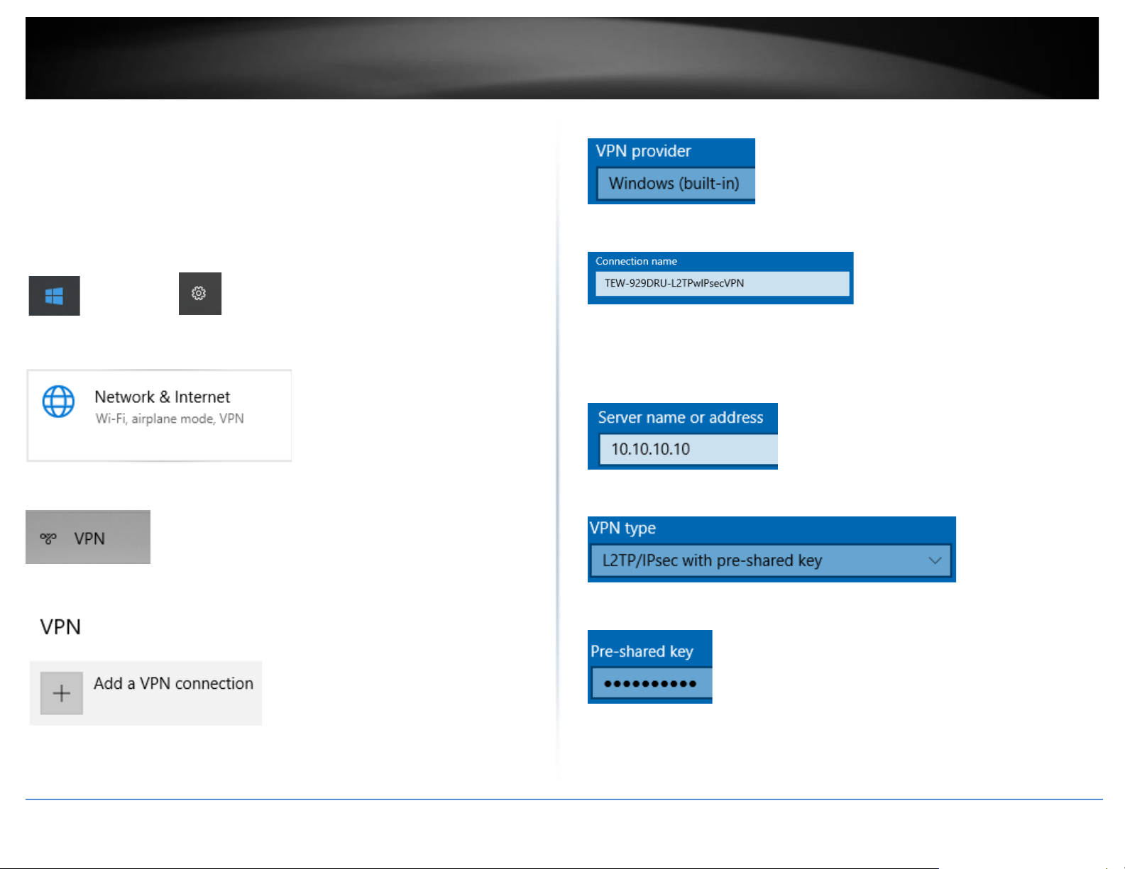
© Copyright 2023 TRENDnet. All Rights Reserved.
58
TRENDnet User’s Guide
TEW-929DRU
Setting up the L2TP VPN client (Windows) with IPsec encryption (PSK)
Note: This procedure provides a basic example how to setup L2TP with IPsec VPN and
establish connectivity using a Windows® 10 client computer. If you are using a different
operating system or mobile device, please refer to the user’s guide/manual of the third
party operating system or device on configuring L2TP with IPsec VPN. The L2TP with
IPsec VPN settings must match with the settings configured on the router.
1. Click the Start button and click the Settings icon.
Start Button Settings icon
2. Click Network & Internet.
3. Click VPN in the left panel.
4. Under VPN, click Add a VPN connection.
5. Click the VPN provider drop-down list and select Windows (built-in).
6. Enter a name in the Connection name field.
7. Enter the Internet WAN IP address, DNS, or dynamic DNS hostname of your router to
connect over the Internet. In the example below, the Internet WAN IP address of the
router is 10.10.10.10. In your router, you can check the WAN IP address under Status
> Overview, under Network in the IPv4 status section.
8. Click the VPN type drop-down list and select L2TP/IPsec with pre-shared key.
9. Enter the IPsec pre-shared key (PSK).
10. Click the Type of sign-in info drop-down list and select User name and password.
Page 67
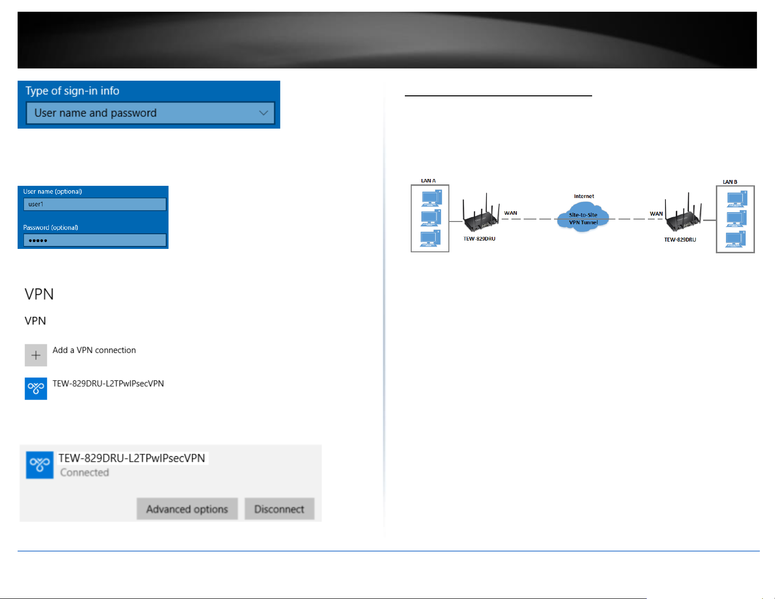
© Copyright 2023 TRENDnet. All Rights Reserved.
59
TRENDnet User’s Guide
TEW-929DRU
10. You can choose to enter the account credentials in the fields provide for
authentication or if not, you will be prompted when attempting to establish PPTP VPN
connection to your TEW-829DRU router. Click Save.
11. Under VPN, the new VPN connection will be listed. Click Connect.
12. The status will display Connected if the PPTP VPN connection was successful.
IPsec (Internet Protocol Security)
Setting up IPsec site-to-site VPN (PSK)
Security > VPN > IPsec
To configure and IPsec site-to-site VPN tunnel with pre-shared key (PSK) between two
routers:
• Ensure that your router is connected to the Internet and computers and
devices are able to access the Internet through your router and make note of
the WAN (Internet) IP assigned to both routers under the Status > Overview
page.
Example:
VPN Router A WAN1 (Internet) IP Address: 10.10.10.10
VPN Router B WAN1 (Internet) IP Address: 10.10.10.20
• Make sure the LAN IP network on each VPN router is a different IP subnet.
Note: Changing the LAN IP address of your router will change the LAN IP
network of your router.
Example:
VPN Router A LAN IP Settings: 192.168.10.1 / 255.255.255.0
VPN Router B LAN IP Settings: 192.168.100.1 / 255.255.255.0
Page 68
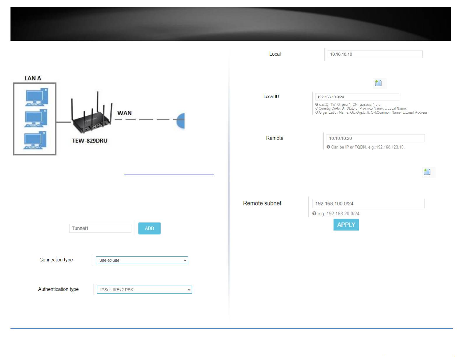
© Copyright 2023 TRENDnet. All Rights Reserved.
60
TRENDnet User’s Guide
TEW-929DRU
VPN Router A Configuration
1. Log into your router management page (see “Access your router management page”
on page 6).
2. Click on Network, click VPN, and click the IPsec tab.
3. Under Overview, enter a tunnel name and click Add. (e.g. Tunnel1)
4. Click the Connection type drop-down list and select Site-to-Site.
5. Click the Authentication type drop-down list and select IPSec IKEv2 PSK.
6. In the Local field, enter the local WAN1 IP address. (e.g. 10.10.10.10) This can also be
a domain name (ex: dynamic DNS host name)
7. In the Local subnet field, enter the local LAN IP subnet. (e.g. 192.168.10.0/24) You
can add additional local subnets by click the add icon (e.g. 192.168.20.0/24)
8. In the Remote field, enter the remote WAN1 IP. (e.g. 10.10.10.20) This can also be a
domain name (ex: dynamic DNS host name)
9. In the Remote subnet field, enter the remote LAN IP subnet. (e.g. 192.168.100.0/24)
and click Apply. You can add additional local subnets by click the add icon (e.g.
192.168.120.0/24)
Page 69
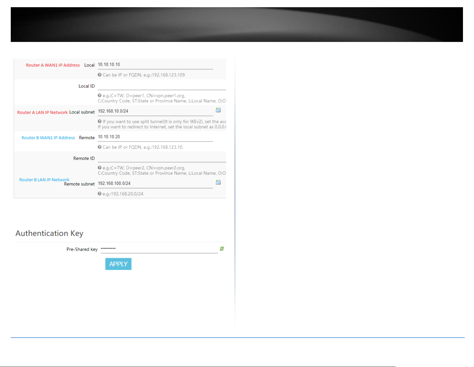
© Copyright 2023 TRENDnet. All Rights Reserved.
61
TRENDnet User’s Guide
TEW-929DRU
Based on the example, the network settings will be the following:
10. Under Authentication Key, enter the Pre-Shared Key (PSK) for the IPsec VPN tunnel
and click Apply. (e.g. 1234567890)
Page 70
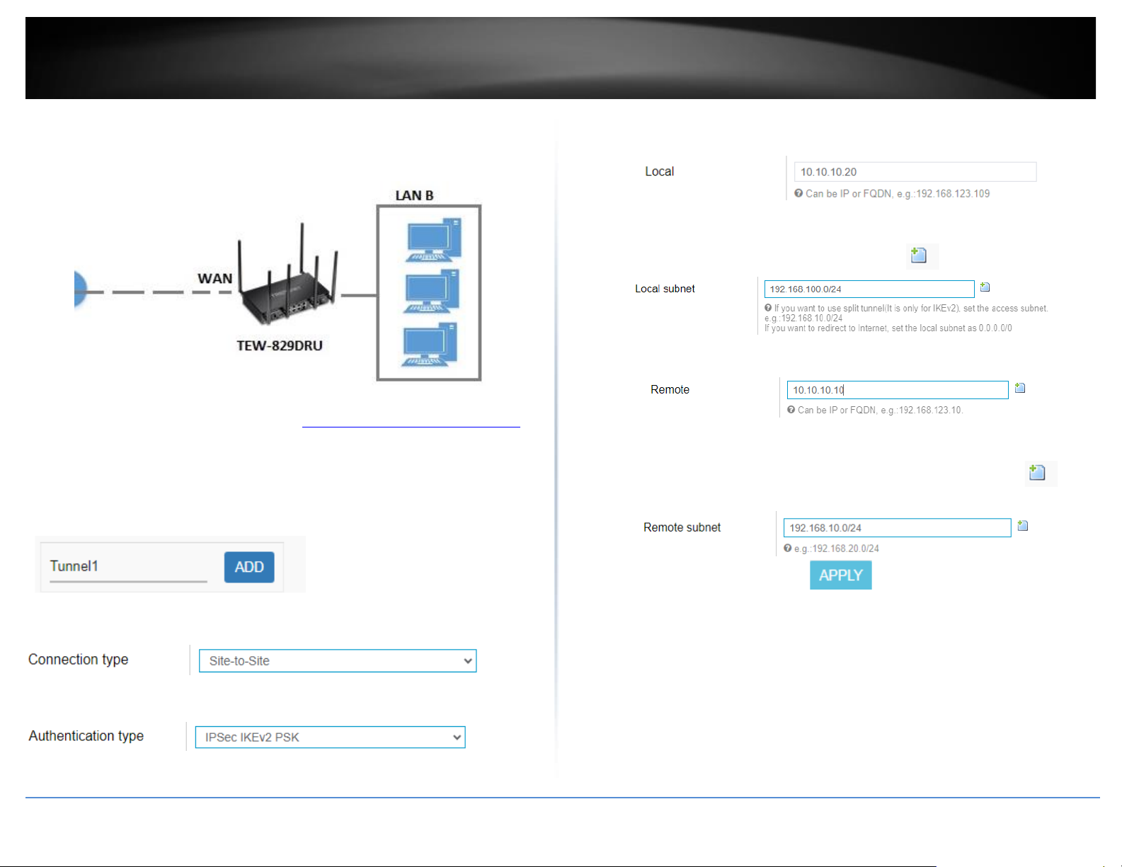
© Copyright 2023 TRENDnet. All Rights Reserved.
62
TRENDnet User’s Guide
TEW-929DRU
VPN Router B Configuration
1. Log into your router management page (see “Access your router management page”
on page 6).
2. Click on Network, click VPN, and click the IPsec tab.
3. Under Overview, enter a tunnel name and click Add. (e.g. Tunnel1)
4. Click the Connection type drop-down list and select Site-to-Site.
5. For the Authentication type drop-down list and select IPSec IKEv2 PSK.
6. For the Local field, enter the local WAN1 IP address. (e.g. 10.10.10.20) This can also
be a domain name (ex: dynamic DNS host name)
7. For the Local subnet field, enter the local LAN IP subnet. (e.g. 192.168.100.0/24) You
can add additional local subnets by click the add icon (e.g. 192.168.120.0/24)
8. For the Remote field, enter the remote WAN1 IP. (e.g. 10.10.10.10) This can also be a
domain name (ex: dynamic DNS host name)
9. For the Remote subnet field, enter the remote LAN IP subnet. (e.g. 192.168.10.0/24)
and click Apply. You can add additional local subnets by click the add icon (e.g.
192.168.20.0/24)
Page 71
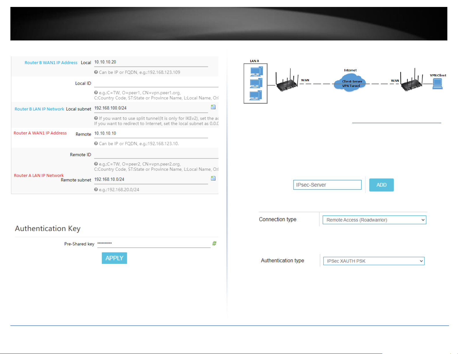
© Copyright 2023 TRENDnet. All Rights Reserved.
63
TRENDnet User’s Guide
TEW-929DRU
Based on the example, the network settings will be the following:
10. Under Authentication Key, enter the Pre-Shared Key (PSK) for the IPsec VPN tunnel
and click Apply. (e.g. 1234567890)
Setting up IPsec server VPN (PSK with xAUTH)
1. Log into your router management page (see “Access your router management page”
on page 6).
2. Click on Network, click VPN, and click the IPsec tab.
3. Under Overview, enter a tunnel name and click Add. (e.g. IPsec_Server)
4. Click the Connection type drop-down list and select Remote Access (Roadwarrior).
5. For the Authentication type drop-down list and select IPSec XAUTH PSK.
6. For the Local field, enter the local WAN1 IP address. (e.g. 10.10.10.10) This can also
be a domain name (ex: dynamic DNS host name)
Page 72
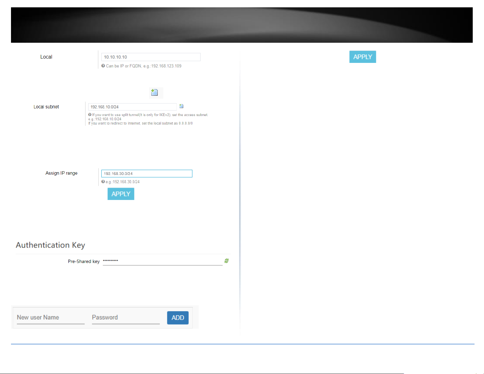
© Copyright 2023 TRENDnet. All Rights Reserved.
64
TRENDnet User’s Guide
TEW-929DRU
7. In the Local subnet field, enter the local LAN IP subnet. (e.g. 192.168.10.0/24) You
can add additional local subnets by click the add icon (e.g. 192.168.20.0/24)
8. In the Assign IP range field, enter the IP address subnet to assign the IPsec VPN client
devices upon connectivity and click Apply. (e.g. 192.168.30.0/24). The IP address
range/subnet should be different from the local LAN IP subnets and also different
from the remote client side.
9. Under Authentication Key, enter the Pre-Shared Key (PSK) for the IPsec VPN tunnel.
(e.g. 1234567890)
10. Under XAUTH Account, enter the User name and Password for the account, then
click Add. Click Apply to save and commit the changes.
Note: For the VPN client computer, you will require a third party IPsec VPN software to
be installed configured matching the IPsec VPN settings on your router. Please refer to
your third party IPsec VPN User’s Guide/Manual for configuring the VPN settings.
Page 73

© Copyright 2023 TRENDnet. All Rights Reserved.
65
TRENDnet User’s Guide
TEW-929DRU
Below is a reference of the additional IPsec VPN settings if you choose to make other
configuration changes to these sections.
• Certificate List – Used for IPsec tunnels requiring the RSA authentication type.
You can create or import IPsec certificates under Administrator > Certificate
Management.
• Local ID/Remote ID – This parameter is only required for IPsec tunnels with the
RSA authentication type. If not using RSA, this additional parameter can be
added for extra security in identification of the IPsec peers. (e.g. Local ID
assigned CN=vpnsite1.trendnet.com and Remote ID CN=vpnsite2.trendnet.com)
• Authentication Key – This is the PSK (pre-shared key) used for IPsec tunnels
requiring the PSK authentication type.
• XAUTH Account – This parameter provides an additional layer of security by
requiring a user name and password for authentication of the IPsec tunnel and
required for IPsec XAUTH PSK tunnel type.
• EAP Account – This parameter provides an additional layer of security by
requiring a user name and password for authentication of the IPsec tunnel and
required for IPsec IKEv2 RSA EAP_MS_CHAPv2 tunnel type.
Phase 1 settings
• Phase 1 auto configure – Checking this option automatically configures the
IPsec Phase 1 parameters for the tunnel. Unchecking this option allows you to
manually set the IPsec Phase 1 parameters.
o Cipher algorithm – The encryption/cipher algorithm used for IPsec
phase 1. AES 256-bit offers the highest degree security.
o Hash algorithm – The authentication/hash algorithm used for IPsec
phase 1. SHA2 256-bit offers highest degree of security.
o DH exchange – The Diffie-Hellman group used for IPsec phase 1 key
exchange. Group 14 (2048 bit) offers the highest degree of security.
Phase 2 settings
• Phase 2 auto configure – Checking this option automatically configures the
IPsec Phase 2 parameters for the tunnel. Unchecking this option allows you to
manually set the IPsec Phase 2 parameters.
o Transform algorithm – The encryption/cipher algorithm used for IPsec
phase 2. AES 256-bit offers the highest degree security.
o Hash algorithm – The authentication/hash algorithm used for IPsec
phase 2. SHA2 256-bit offers highest degree of security.
o PFS exchange – The Perfect Forward Secrecy group used for IPsec
phase 2. PFS adds additional security to the IPsec tunnel by forcing renegotiation of phase 1 keys for every new pair of phase 2 SAs (security
associations) established. Group 14 (2048 bit) offers the highest
degree of security.
• DPD (Dead Peer Detection) – DPD implements a keep alive/monitoring
function to the IPsec tunnel to check if IPsec peers are still active and
responding.
o DPD action - Sets the action when IPsec peers do not respond to DPD
messages within the DPD delay interval. Clear will automatically close
the IPsec connection and will not attempt to re-negotiate the
connection, Hold will keep the connection and will attempt to renegotiate the connection on-demand only when new traffic is sent
through the tunnel, Restart will immediately force re-negotiation of
the connection.
o DPD delay – Sets the time interval when DPD messages are sent o
IPsec peers to check the alive status.
o DPD timeout – Sets the maximum timeout interval when IPsec
connections are completely deleted due to inactivity.
Page 74
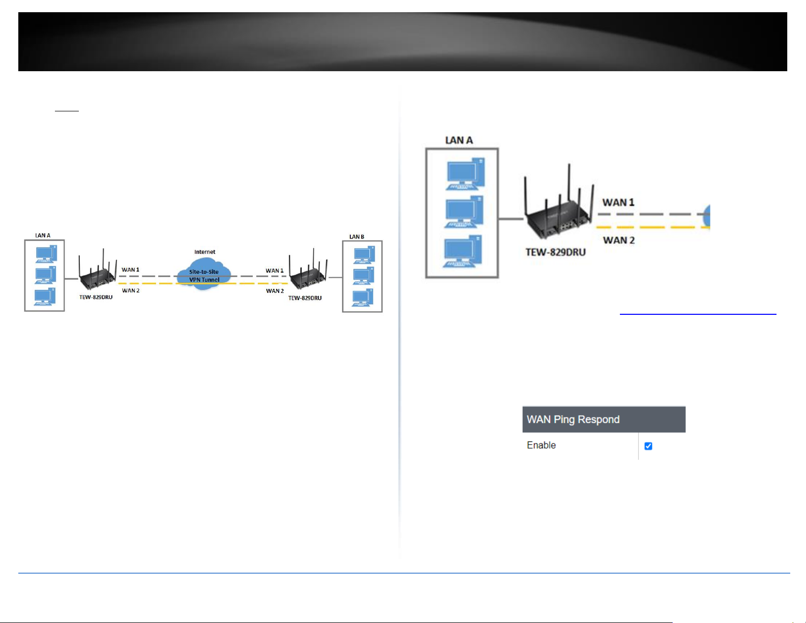
© Copyright 2023 TRENDnet. All Rights Reserved.
66
TRENDnet User’s Guide
TEW-929DRU
Setting up IPsec site-to-site VPN Failover (PSK)
• Note: IPsec VPN failover is only supported on firmware 1.0.0.33 or above. This
configuration will only work when multiple WAN configuration is set to WAN1
(Failover to WAN2), WAN2 (Failover to WAN1), Load Balance (weight cannot be
set to 50%:50%).
Network > VPN > IPsec
VPN failover configuration allows you to add redundancy/fault tolerance to your IPsec
VPN tunnel connectivity.
To configure and IPsec site-to-site VPN tunnel failover with pre-shared key (PSK)
between two routers:
• Ensure that your router is connected to the Internet and computers and
devices are able to access the Internet through the WAN1 and WAN2 interfaces
on your router and make note of the WAN1 and WAN2 IP addresses assigned
to both routers under the Status > Overview page. In this example, we will
assume the following static IP WAN info. and LAN IP settings below.
Example:
VPN Router A WAN1 (Internet) IP Address: 10.10.10.85 / 255.255.255.192
VPN Router A WAN2 (Internet) IP Address: 10.10.10.130 / 255.255.255.192
VPN Router B WAN1 (Internet) IP Address: 172.16.0.1 / 255.255.255.192
VPN Router B WAN1 (Internet) IP Address: 172.16.0.62 / 255.255.255.192
• Make sure the LAN IP network on each VPN router is a different IP subnet.
Note: Changing the LAN IP address of your router will change the LAN IP
network of your router.
Example:
VPN Router A LAN IP Settings: 192.168.200.1 / 255.255.255.0
VPN Router B LAN IP Settings: 192.168.210.1 / 255.255.255.0
VPN Router A Configuration
1. Log into your router management page (see “Access your router management page”
on page 6).
2. Click on Security, click Firewall, and click the General Settings tab.
3. Check the Enable under WAN Ping Respond and click Apply to save and commit the
configuration changes.
4. Click on Multi-WAN/QoS and click on Multi WAN.
5. Under the Link Tracking section, check Enable Tracking on both WAN1 and WAN2,
and enter an IP address or IP addresses on the Internet to check for connectivity and
Page 75
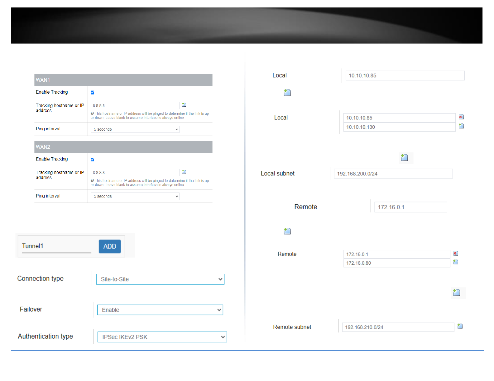
© Copyright 2023 TRENDnet. All Rights Reserved.
67
TRENDnet User’s Guide
TEW-929DRU
quickly determine if the WAN interface is up or down (e.g. 8.8.8.8). Set the Ping
Interval to 3 seconds, and Fail Count to 1 for both WAN1 and WAN2 and click Apply
to save and commit the configuration changes.
6. Click on Security, click VPN, and click the IPsec tab.
7. Under Overview, enter a tunnel name and click Add. (e.g. Tunnel1)
8. Click the Connection type drop-down list and select Site-to-Site.
9. Click the Failover drop-down list and select Enable.
10. Click the Authentication type drop-down list and select IPSec IKEv2 PSK.
11. In the Local field, enter the local WAN1 IP address. (e.g. 10.10.10.85) This can also
be a domain name (ex: dynamic DNS host name)
12. Click to add an additional IP address and enter the local WAN2 IP address (e.g.
10.10.10.130).
13. In the Local subnet field, enter the local LAN IP subnet. (e.g. 192.168.200.0/24) You
can add additional local subnets by click the add icon (e.g. 192.168.20.0/24)
14. In the Remote field, enter the remote WAN1 IP address. (e.g. 172.16.0.1) This can
also be a domain name (ex: dynamic DNS host name)
15. Click to add an additional IP address and enter the remote WAN2 IP address
(e.g. 172.16.0.80).
16. In the Remote subnet field, enter the remote LAN IP subnet. (e.g. 192.168.210.0/24)
and click Apply. You can add additional local subnets by click the add icon (e.g.
192.168.30.0/24)
Page 76
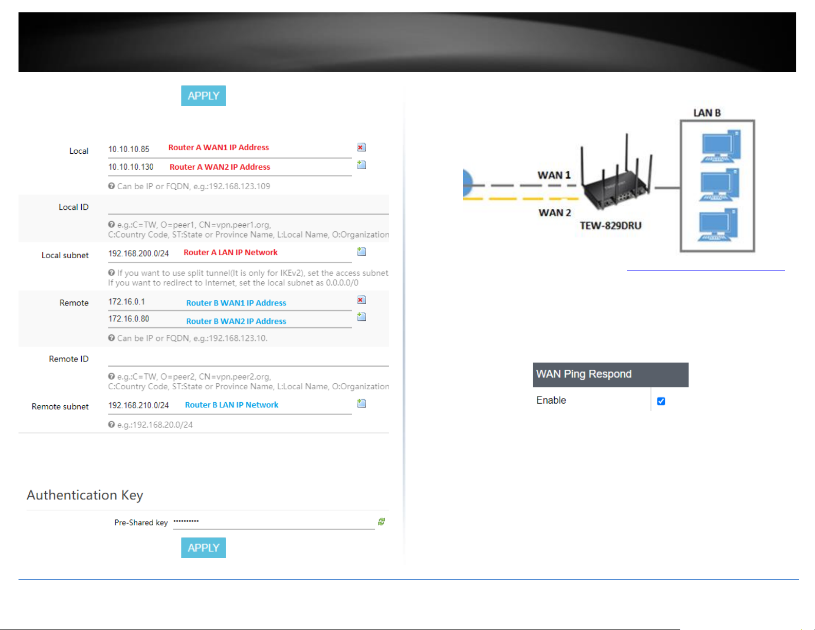
© Copyright 2023 TRENDnet. All Rights Reserved.
68
TRENDnet User’s Guide
TEW-929DRU
Based on the example, the network settings will be the following:
17. Under Authentication Key, enter the Pre-Shared Key (PSK) for the IPsec VPN tunnel
and click Apply. (e.g. 1234567890)
VPN Router B Configuration
1. Log into your router management page (see “Access your router management page”
on page 6).
2. Click on Security, click Firewall, and click the General Settings tab.
3. Check the Enable under WAN Ping Respond and click Apply to save and commit the
configuration changes.
4. Click on Multi-WAN/QoS and click on Multi WAN.
5. Under the Link Tracking section, check Enable Tracking on both WAN1 and WAN2,
and enter an IP address or IP addresses on the Internet to check for connectivity and
quickly determine if the WAN interface is up or down (e.g. 8.8.8.8). Set the Ping Interval
to 3 seconds, and Fail Count to 1 for both WAN1 and WAN2 and click Apply to save and
commit the configuration changes.
Page 77
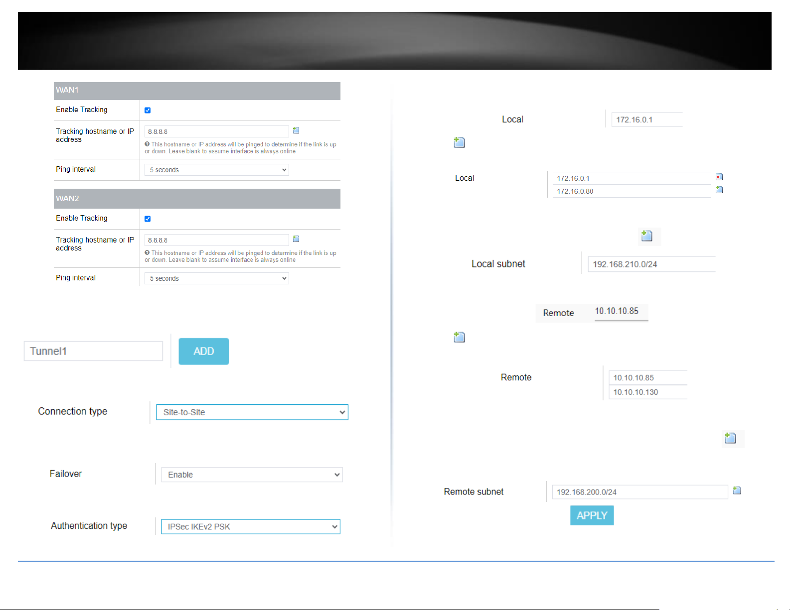
© Copyright 2023 TRENDnet. All Rights Reserved.
69
TRENDnet User’s Guide
TEW-929DRU
6. Click on Network, click VPN, and click the IPsec tab.
7. Under Overview, enter a tunnel name and click Add. (e.g. Tunnel1)
8. Click the Connection type drop-down list and select Site-to-Site.
9. Click the Failover drop-down list and select Enable.
10. Click the Authentication type drop-down list and select IPSec IKEv2 PSK.
11. In the Local field, enter the local WAN1 IP address. (e.g. 172.16.0.1) This can also be
a domain name (ex: dynamic DNS host name)
12. Click to add an additional IP address and enter the local WAN2 IP address (e.g.
172.16.0.80).
13. In the Local subnet field, enter the local LAN IP subnet. (e.g. 192.168.210.0/24) You
can add additional local subnets by click the add icon (e.g. 192.168.30.0/24)
14. In the Remote field, enter the remote WAN1 IP address. (e.g. 172.16.0.1) This can
also be a domain name (ex: dynamic DNS host name)
15. Click to add an additional IP address and enter the remote WAN2 IP address
(e.g. 172.16.0.80).
16. In the Remote subnet field, enter the remote LAN IP subnet. (e.g. 192.168.200.0/24)
and click Apply. You can add additional local subnets by click the add icon (e.g.
192.168.20.0/24)
Page 78
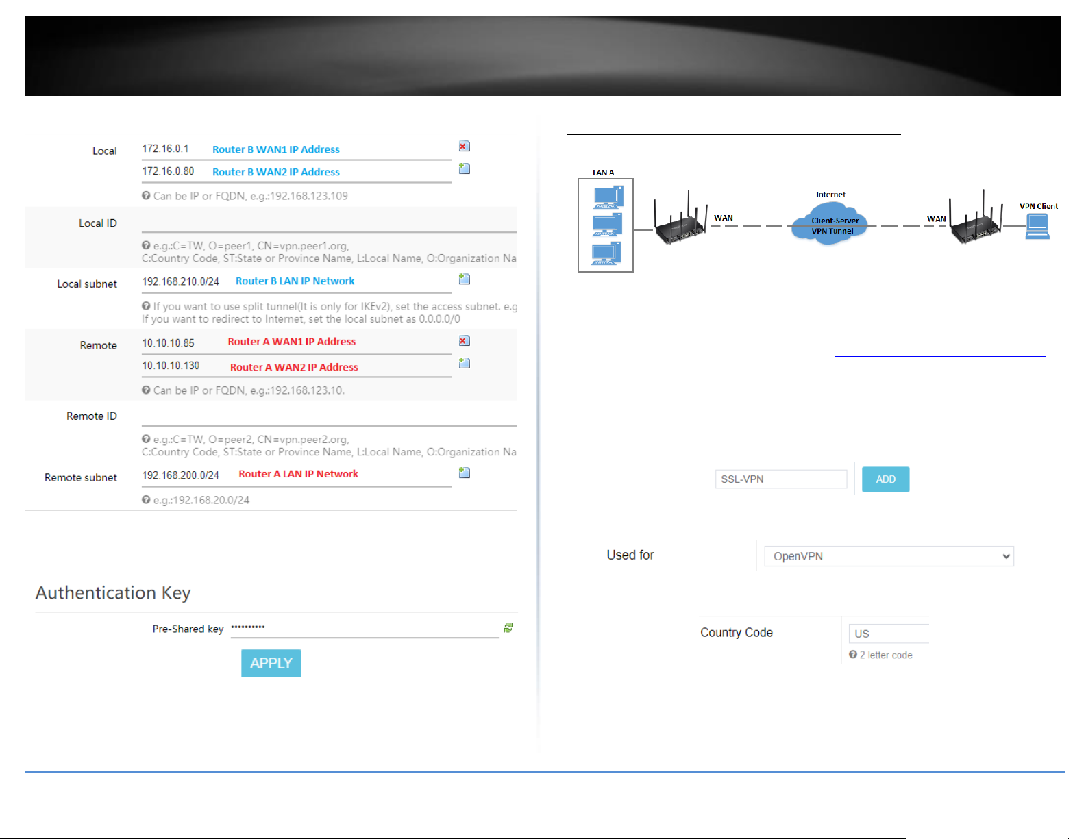
© Copyright 2023 TRENDnet. All Rights Reserved.
70
TRENDnet User’s Guide
TEW-929DRU
Based on the example, the network settings will be the following:
17. Under Authentication Key, enter the Pre-Shared Key (PSK) for the IPsec VPN tunnel
and click Apply. (e.g. 1234567890)
Secure Socket Layer VPN (SSL) / OpenVPN
Network > VPN > OpenVPN
SSL VPN Server Setup
1. Log into your router management page (see “Access your router management page”
on page 6).
2. Click on Management and click Certificate Management.
3. Enter a name for the certificate to use for SSL VPN and click Add. (e.g. SSL-VPN)
4. Click the Used for drop-down list and select OpenVPN.
5. In the Country Code field, enter the two letter country code. (e.g. US)
6. In the State or Province Name field, enter the full name of the state or province. (e.g.
California)
Page 79
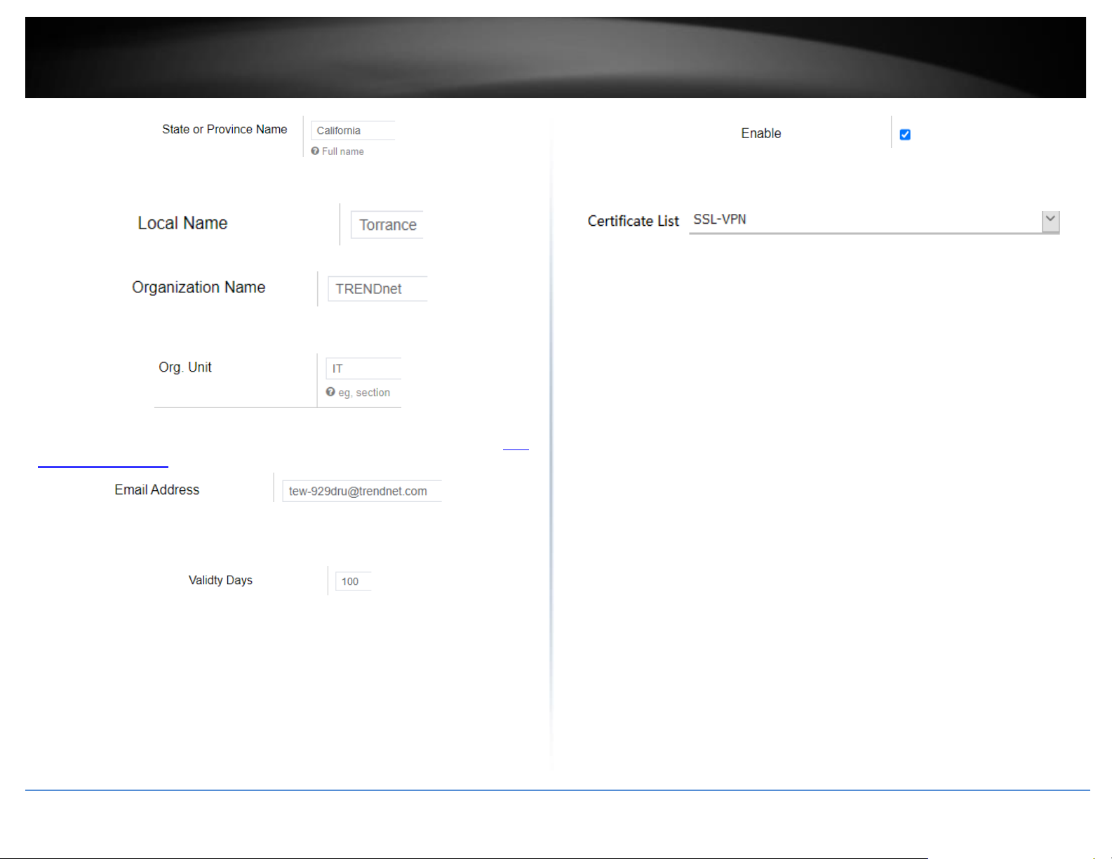
© Copyright 2023 TRENDnet. All Rights Reserved.
71
TRENDnet User’s Guide
TEW-929DRU
7. In the Local Name field, enter the city name. (e.g. Torrance)
8. In the Organization Name field, enter your company name (e.g. TRENDnet)
9. In the Org. Unit field, enter the section, group, or department. (e.g. IT)
10. In the Email Address field, enter the email address used for the certificate. (e.g. tew-
11. In the Validity Days field, enter the number of days the certificate will be valid and
click Apply to save and commit the changes.. (e.g. 100)
12. Click on Security, click VPN, and click the OpenVPN Server tab.
13. Check the Enable option to enable the SSL VPN server.
Note: You may receive a notification if Dynamic DNS is not configured on your router. If
you are using VPN, it is not required however, strongly recommended to setup the
Dynamic DNS feature on your router to prevent any issues with VPN connectivity if
your public (WAN) Internet IP address dynamically changes.
14. In the Certificate List drop-down list, select the name of the OpenVPN certificate
you created and click Apply to save and commit the changes. (e.g. SSL-VPN)
15. Next to Client configuration file, click Export to download the configuration files for
the VPN client computer.
Note: Please do not change the filename for Windows installation. If installing in Linux,
the .ovpn extension must be changed to .conf.
Folder paths for SSL VPN client configuration files:
Windows: C:\Program Files\OpenVPN\config
Linux: /etc/openvpn
Below is a reference of the additional SSL VPN settings if you choose to make other
configuration changes to these sections.
Note: Changing any settings will require you to export a new client configuration file.
• Port – Used to change the default SSL VPN server port.
• Server – Used to change the default IP address subnet and IP address range to
distribute to SSL VPN clients.
• Proto – Used to change the default protocol. UDP or TCP.
• Connect Type – Changing this setting will change the access level of your SSL
VPN clients.
o LAN Access – This setting will allow your SSL VPN clients access to your
LAN network and the Internet.
o Internet Redirect – This setting will allow your SSL VPN clients access
only the Internet only via full tunneling but no access to your LAN
network
• Cipher – Select the cipher/encryption algorithm used for SSL VPN client
connections. AES-256-CBC offers the highest degree security.
• Auth – The authentication/hash algorithm used for SSL VPN client connections.
SHA256 offers highest degree of security.
Page 80
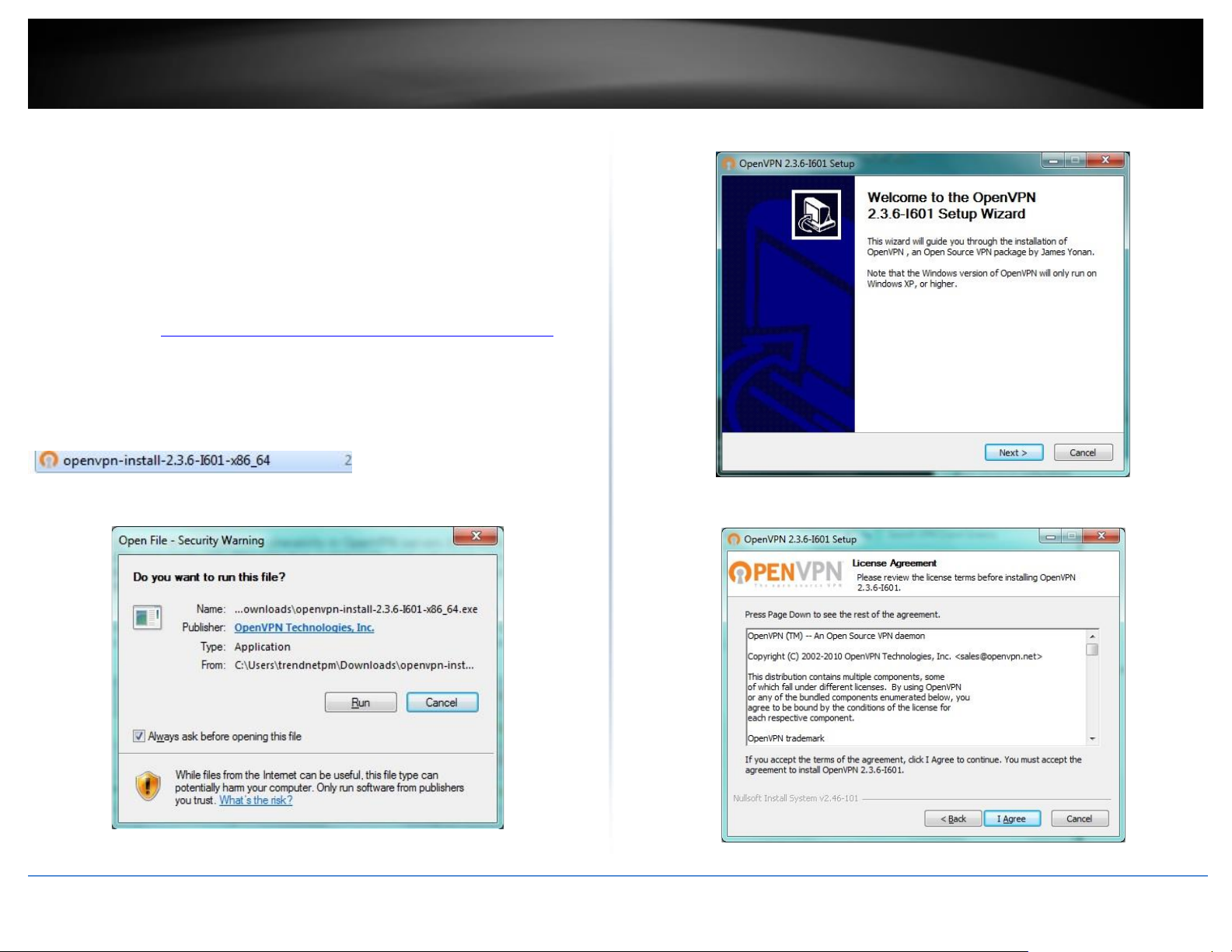
© Copyright 2023 TRENDnet. All Rights Reserved.
72
TRENDnet User’s Guide
TEW-929DRU
• Enable client authentication – Checking this option will require additional
security by means of user name and password authentication in addition to the
standard encryption/authentication protocols. You will need to add a user
name and password under Client Authentication Account.
SSL VPN Client Setup (Windows)
1. Make sure to copy or move the configuration files downloaded from your router to
the VPN client computer and that your client computer has access to the Internet.
2. Download the appropriate OpenVPN software version for your operating system from
the following URL: https://openvpn.net/index.php/open-source/downloads.html
Note: Please note there is also a link in the description in the router management page
under Advanced > Setup > VPN.
3. Once you have downloaded the software, navigate to the location where you
downloaded the file and double click to start the installation.
4. If prompted to run the file, click Run.
5. At the installation window, click Next.
6. At the license agreement window, review the license agreement and click I Agree.
Page 81
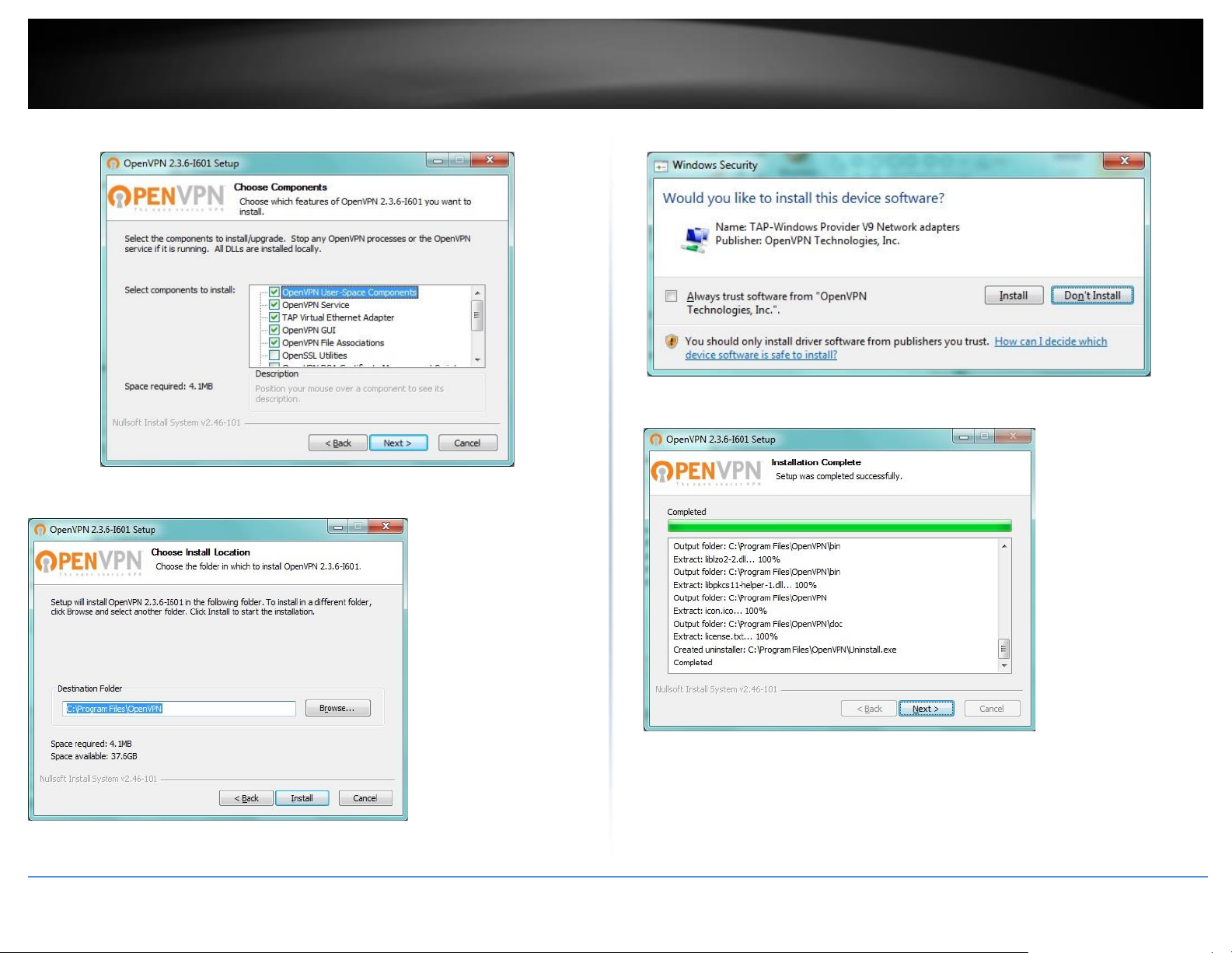
© Copyright 2023 TRENDnet. All Rights Reserved.
73
TRENDnet User’s Guide
TEW-929DRU
7. At the choose components window, click Next.
8. At the install location window, click Install.
9. At the prompt to install the TAP-Windows adapter, click Install.
10. At the installation completion window, click Next.
Page 82
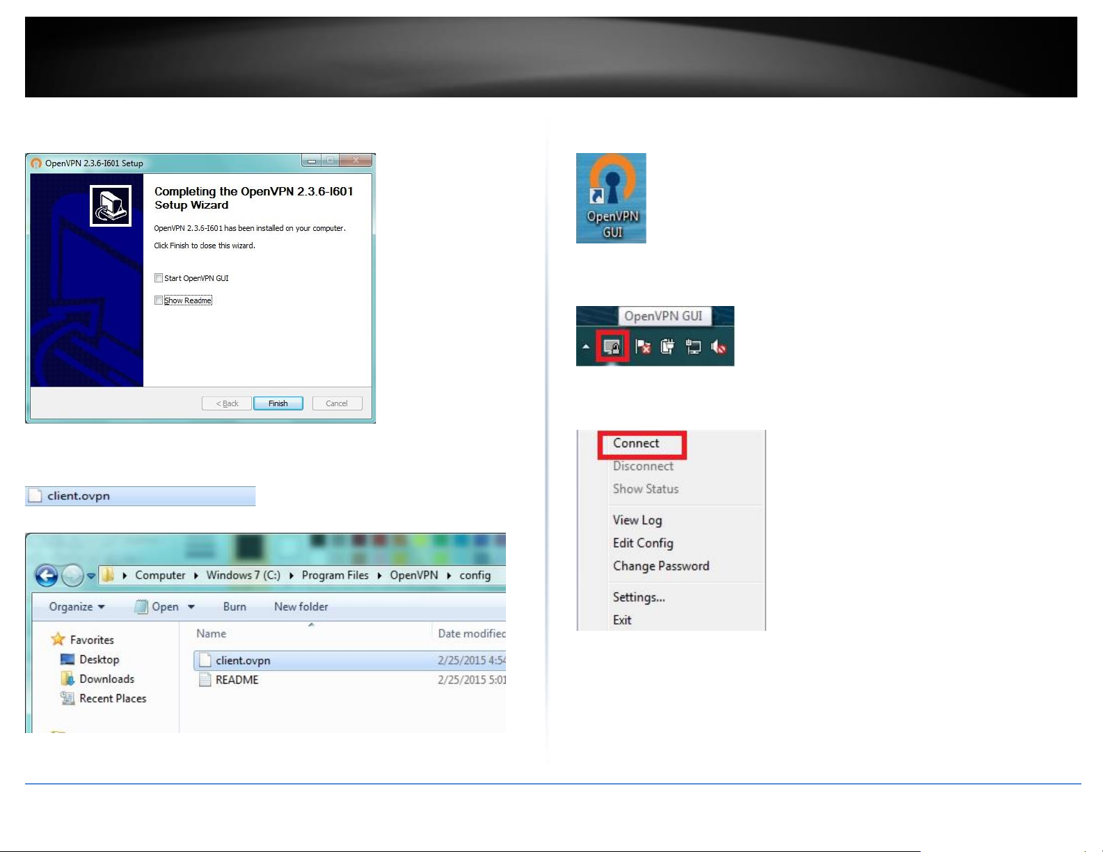
© Copyright 2023 TRENDnet. All Rights Reserved.
74
TRENDnet User’s Guide
TEW-929DRU
11. Make sure to uncheck the “Show Readme” and “Start OpenVPN GUI” options and
click Finish.
12. Copy the client configuration file(s) (client.ovpn) downloaded from the router to the
following path without any sub-folders.
C:\Program Files\OpenVPN\config
13. Double-click on the OpenVPN GUI shortcut on your desktop to start the OpenVPN
Client software.
14. The OpenVPN system tray icon will appear in the bottom right corner. Right-click the
icon to display the configuration menu.
15. After right-clicking the icon, the menu will appear. Click Connect to establish your
VPN connection to your router.
Page 83
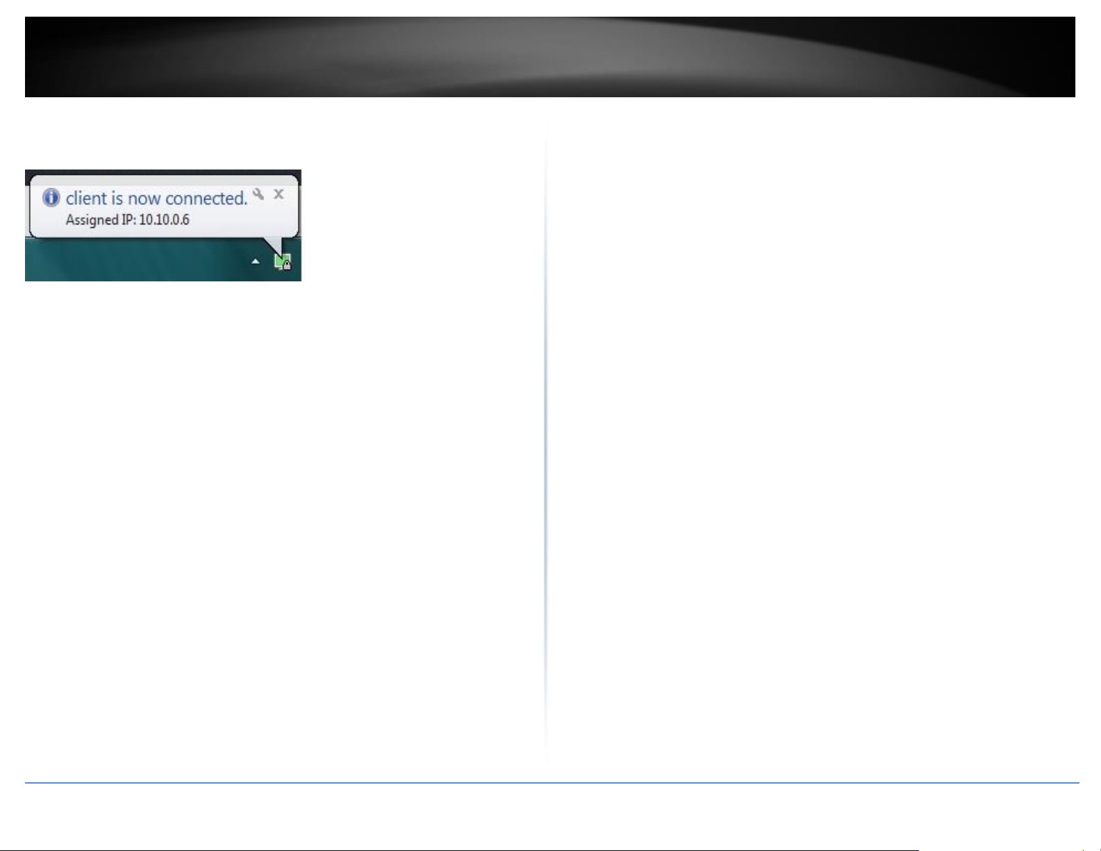
© Copyright 2023 TRENDnet. All Rights Reserved.
75
TRENDnet User’s Guide
TEW-929DRU
16. If the VPN connection is successful, you will receive the notification below in the
bottom right corner. You will be able to access resources securely from your router LAN
network over the Internet such as shared folders, media, files, etc.
Note: To disconnect your VPN client connection, right click OpenVPN system tray icon
and select Disconnect.
Page 84

© Copyright 2023 TRENDnet. All Rights Reserved.
76
TRENDnet User’s Guide
TEW-929DRU
Certificate Management
Administrator > Certificate Management
The certificate management allows you to create, import, and export security
certificates used for IPsec RSA and SSL VPN (OpenVPN) identification and authentication
in IPsec RSA or SSL VPN (OpenVPN) configuration.
1. Log into your router management page (see “Access your router management page”
on page 6).
2. Click on Management and click on Certificate Management.
3. Under Local Certificates, enter a name for the certificate and click Add. (e.g. IPsecVPN
or OpenVPN)
4. Click the Used for drop-down list and select the appropriate VPN method the
certificate will be used for, IPsec or OpenVPN.
5. Review the settings below. When complete, click Apply to save and commit your
changes. After you have created the appropriate VPN certificate, the certificate will be
available under the IPsec or Open VPN configuration settings under Network > VPN.
IPsec – Below are the parameters you can set for the certificate. The only required
parameters for an IPsec RSA certificate are Common Name (Server), Common Name
(Client), and Valid Days.
• Certificate Name – Enter the name for the certificate.
• Used for – Click the drop-down list and select IPsec.
• Country Code – Enter the 2 letter country code for the certificate. (e.g. US)
Note: Setting this parameter is optional for IPsec VPN RSA.
• State or Province Name – Enter the name of the state or province for the
certificate. (e.g. California)
Note: Setting this parameter is optional for IPsec VPN RSA.
• Local Name – Enter the name of the city for the certificate. (e.g. Torrance)
Note: Setting this parameter is optional for IPsec VPN RSA.
• Organization Name – Enter the company name for the certificate (e.g. TRENDnet)
Note: Setting this parameter is optional for IPsec VPN RSA.
• Org. Unit – Enter the department or group name for the certificate (e.g. IT)
Note: Setting this parameter is optional for IPsec VPN RSA.
• Email Address – Enter the email address contact for the certificate (e.g.
Note: Setting this parameter is optional for IPsec VPN RSA
• Common Name (Server) – Enter the host + domain name of first site/IPsec tunnel
endpoint. (e.g. site1.ipsecvpn.local)
Note: Setting this parameter is required for IPsec VPN RSA
• Common Name (Client) – Enter the host + domain name of the second site/IPsec
tunnel endpoint. (e.g. site2.ipsecvpn.local)
Note: Setting this parameter is required for IPsec VPN RSA
• Valid Days – Enter the amount of days the certificate will be valid before expiration.
The first day will be set as the day the certificate was created. (e.g. 100)
Note: Setting this parameter is required for IPsec VPN RSA
• SAN (Server) – Enter the IP address, email, or domain name of the SAN (storage
array network server) of the first site/IPsec tunnel endpoint. (e.g. 192.168.10.20)
Note: Setting this parameter is optional for IPsec VPN RSA.
• SAN (Client) - Enter the IP address, email, or domain name of the SAN (storage
array network server) of the second site/IPsec tunnel endpoint. (e.g.
192.168.100.20)
Note: Setting this parameter is optional for IPsec VPN RSA
• Password – Enter the import/export password for the certificate.
Note: Setting this parameter is optional for IPsec VPN RSA.
Page 85
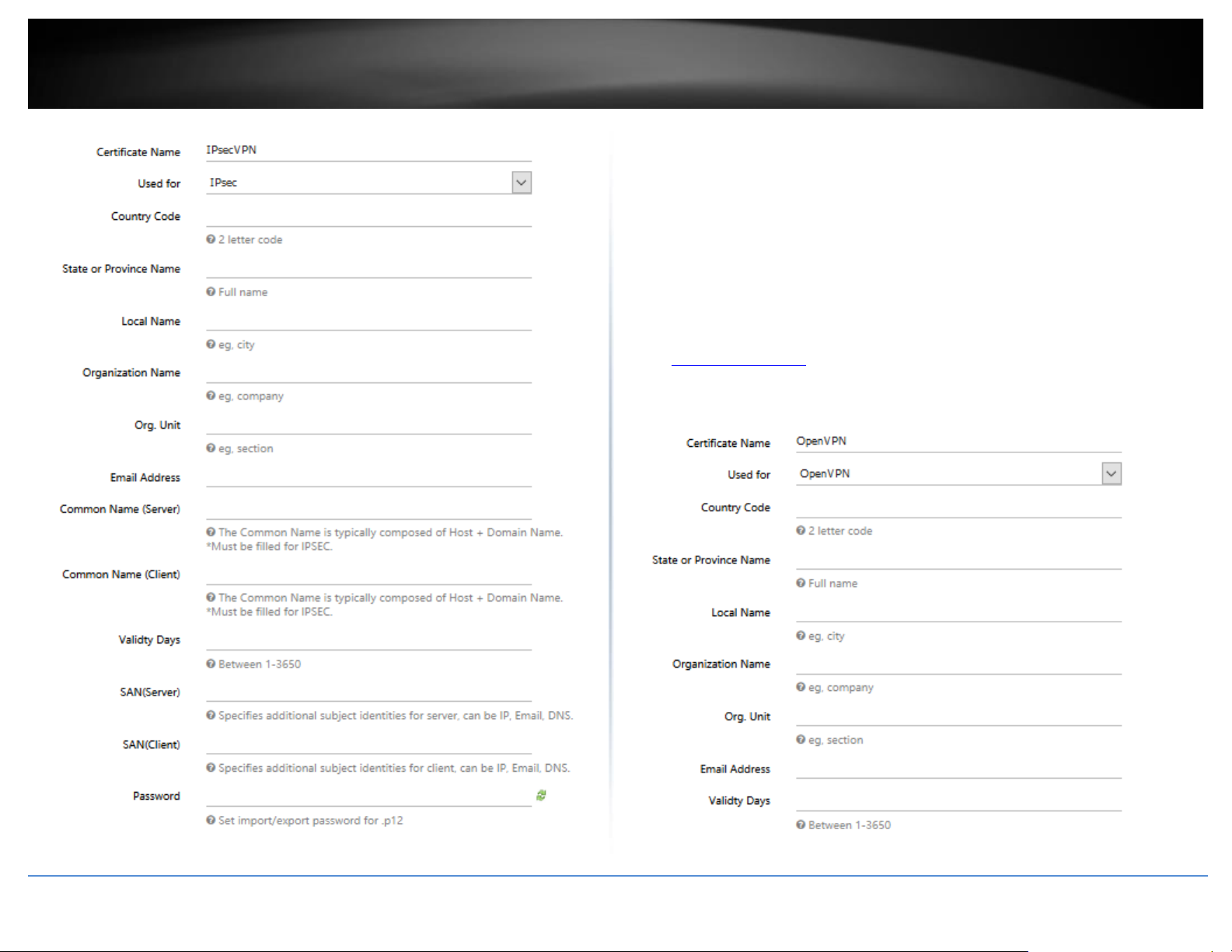
© Copyright 2023 TRENDnet. All Rights Reserved.
77
TRENDnet User’s Guide
TEW-929DRU
OpenVPN – Below are the parameters you can set for the certificate. All parameters are
required for the SSL VPN (OpenVPN) certificate.
• Certificate Name – Enter the name for the certificate.
• Used for – Click the drop-down list and select OpenVPN.
• Country Code – Enter the 2 letter country code for the certificate. (e.g. US)
• State or Province Name – Enter the name of the state or province for the
certificate. (e.g. California)
• Local Name – Enter the name of the city for the certificate. (e.g. Torrance)
• Organization Name – Enter the company name for the certificate (e.g. TRENDnet)
• Org. Unit – Enter the department or group name for the certificate (e.g. IT)
• Email Address – Enter the email address contact for the certificate (e.g.
• Valid Days – Enter the amount of days the certificate will be valid before expiration.
The first day will be set as the day the certificate was created. (e.g. 100)
Page 86
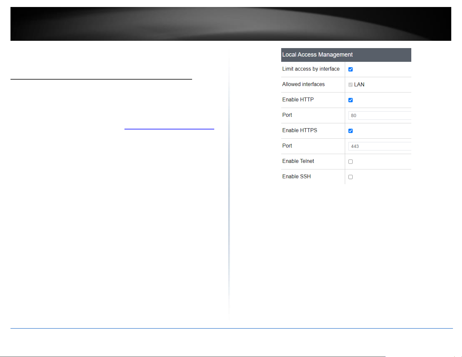
© Copyright 2023 TRENDnet. All Rights Reserved.
78
TRENDnet User’s Guide
TEW-929DRU
Router Maintenance and Monitoring
Managing access to the router management interface
Administrator > Access Management
This section will allow you to restrict access router management access to specific
interfaces. By default, management access to the web interface (HTTP) is restricted only
to the LAN interface.
1. Log into your router management page (see “Access your router management page”
on page 6).
2. Click on Management and click on Access Management.
3. Review the settings below. When complete, click Apply to save and commit your
changes.
Local Access Management
• Limit access by interface – Checking this option will allow you to select specific local
interfaces (e.g. LAN, VLAN) that are allowed access to the router management
interface.
o Allowed interfaces – The available local interfaces will be in this
section. (e.g. Selecting LAN will only allow management access from
the LAN and all other VLAN interfaces will be denied.)
• Enable HTTPS – Checking this option will enable secure HTTPS (SSL) access to the
router management page on the selected local interfaces.
• Enable Telnet – Checking this option will enable command line interface access via
Telnet on the selected local interfaces.
• Enable SSH – Checking this option will enabled secure command line interface
access via SSH (Secure Shell) on the selected local interfaces.
Remote Access Management
• Limit access by interface – Checking this option will allow you to select specific
WAN interfaces (e.g. WAN1, WAN2) that are allowed access to the router
management interface over the Internet.
o Allowed interfaces – The WAN1 and WAN2 interfaces will be in this
section. (e.g. Selecting WAN1 will only allow management access from
the WAN1 interface and will deny management access on the WAN2
interface.
• Enable HTTPS – Checking this option will enable secure HTTPS (SSL) access to the
router management page on the selected WAN interfaces.
• Enable Telnet – Checking this option will enable command line interface access via
Telnet on the selected WAN interfaces.
• Enable SSH – Checking this option will enabled secure command line interface
access via SSH (Secure Shell) on the selected WAN interfaces.
Page 87
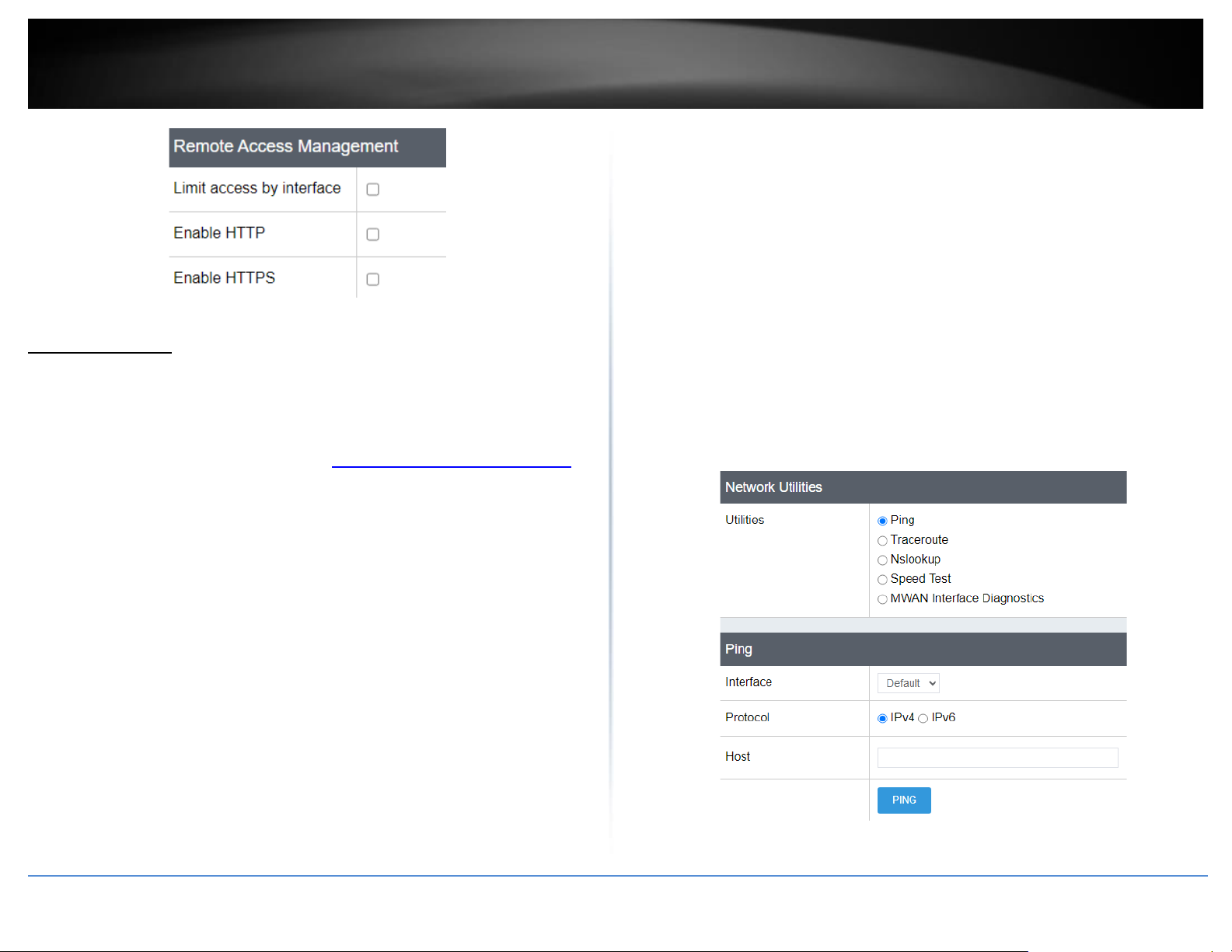
© Copyright 2023 TRENDnet. All Rights Reserved.
79
TRENDnet User’s Guide
TEW-929DRU
Diagnostic tools
Tools > Diagnostics
This section includes network tools and utilities for testing connectivity and
troubleshooting.
1. Log into your router management page (see “Access your router management page”
on page 6).
2. Click on Tools and click on Diagnostics.
3. Review the settings below.
Network Utilities
• Ping – This tool conducts a basic ping/connectivity test to a host IP address or
domain name. After selecting and entering all of the required parameters, click
PING to start the connectivity test and the results will appear at the bottom of the
page.
o Interface – Select the interface used to run the connectivity test.
▪ Default – Uses the internal loopback interface to conduct the
connectivity test.
▪ WAN1/WAN2 – You can select either WAN1 or WAN2 to
conduct the connectivity test through a specific WAN
interface for troubleshooting.
o Protocol – Select the IP protocol version for the connectivity test, IPv4
or IPv6.
o Host – Enter the host IP address or domain name to test connectivity.
• Traceroute – This tool conducts a test to check the routing path taken to reach a
specific destination host IP address or domain name. After selecting and entering all
of the required parameters, click TRACEROUTE to start the connectivity test and the
results will appear at the bottom of the page.
o Interface – Select the interface used to run the connectivity test.
▪ Default – Uses the internal loopback interface to conduct the
connectivity test.
▪ WAN1/WAN2 – You can select either WAN1 or WAN2 to
conduct the connectivity test through a specific WAN
interface for troubleshooting.
o Protocol – Select the IP protocol version for the connectivity test, IPv4
or IPv6.
o Host – Enter the host IP address or domain name to test connectivity.
• Nslookup – This tool conducts a test to check domain name resolution to an IP
address. After entering in the domain name to resolve, click NSLOOKUP to start the
resolution test and the results will appear at the bottom of the page.
o Host – Enter the host IP address or domain name to test resolution.
Page 88
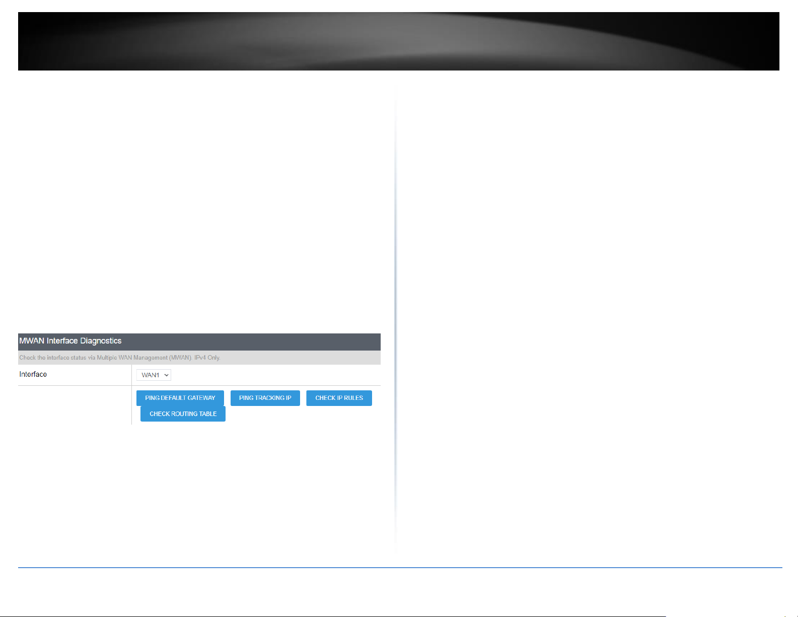
© Copyright 2023 TRENDnet. All Rights Reserved.
80
TRENDnet User’s Guide
TEW-929DRU
Speed Test – This section allows for a speed test of your ISP connection
• Interface – Select the WAN interface to conduct testing
• Default – Uses the internal loopback interface to conduct the connectivity test
• WAN1/WAN2 – You can select either WAN1 or WAN2 to conduct the speed
test through a specific WAN interface.
• Server – Select the server to run a speed test with
MWAN Interface Diagnostics – This section allows to conduct connectivity testing on
the multi-WAN configuration.
• Interface – Select the WAN interface to conduct testing.
o Ping Default Gateway – This will conduct a ping connectivity test to
the default gateway IP address of the selected WAN interface.
o Ping Tracking IP – This will conduct a ping connectivity test to the
tracking IP configured under Network > Multiple WAN in the Link
Tracking section for the selected WAN interface.
o Check IP Rules – This will display the current IP rules configured for
the selected WAN interface.
o Check Routing Table – This will display the current default route
configured for the selected WAN interface.
Page 89
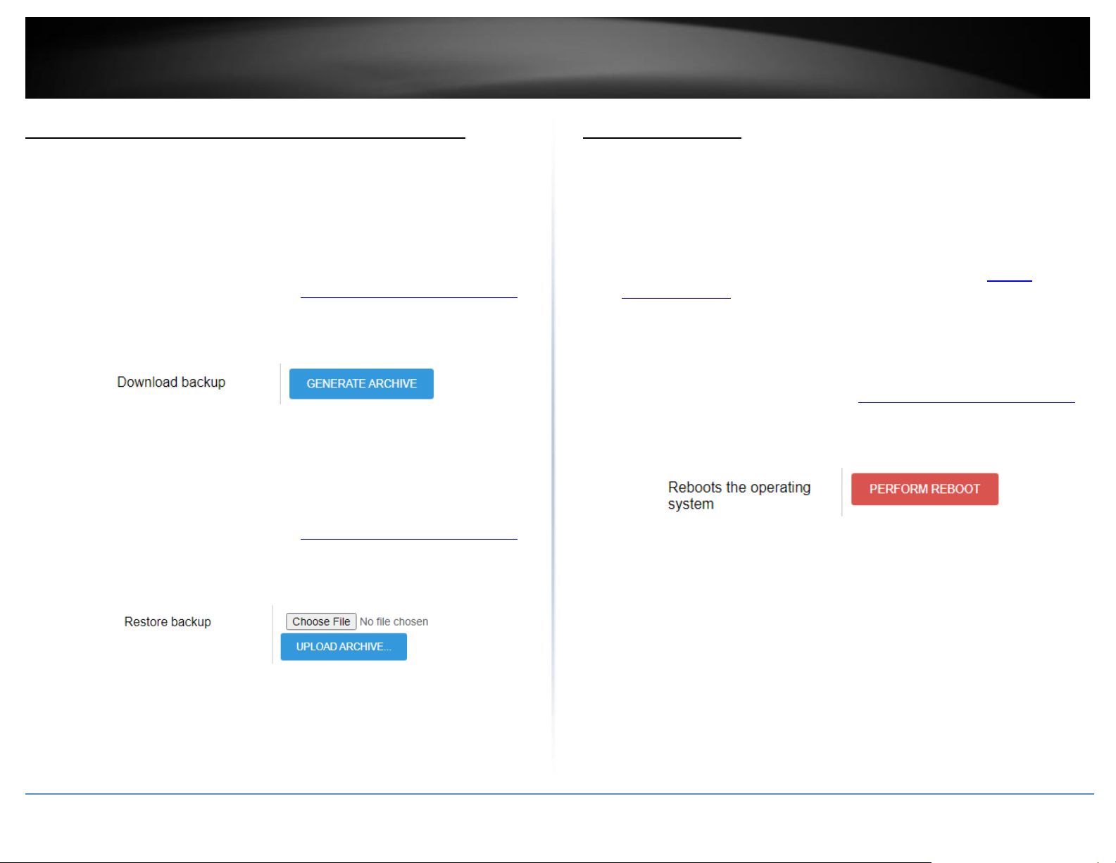
© Copyright 2023 TRENDnet. All Rights Reserved.
81
TRENDnet User’s Guide
TEW-929DRU
Backup and restore your router configuration settings
Management > Firmware / Configuration
You may have added many customized settings to your router and in the case that you
need to reset your router to factory defaults, all your customized settings would be lost
and would require you to manually reconfigure all of your router settings instead of
simply restoring from a backed up router configuration file.
To backup your router configuration:
1. Log into your router management page (see “Access your router management page”
on page 6).
2. Click on Management, then click on Firmware / Configuration
3. Next to Download backup, click Generate Archive.
4. Depending on your web browser settings, you may be prompted to save the
configuration file (specify the location) or the file may be downloaded automatically
to the web browser settings default download folder. (Default Filename: backup-TEW-
929DRU-YYYY-MM-DD.dat)
To restore your router configuration:
1. Log into your router management page (see “Access your router management page”
on page 8).
2. Click on Administrator, then click on Backup / Flash Firmware.
3. Next to Restore backup, click Browse or Choose File.
4. A separate file navigation window should open.
5. Select the router configuration file to restore and click Upload Archive (Default
Filename: backup-TEW-929DRU-YYYY-MM-DD.dat). If prompted, click Yes or OK.
6. Wait for the router to restore settings.
Reboot your router
Management > Reboot
You may want to restart your router if you are encountering difficulties with your router
and have attempted all other troubleshooting.
There are two methods that can be used to restart your router.
• Turn the router off for 10 seconds using the router On/Off switch located on the
rear panel of your router or disconnecting the power port, see “Product
Hardware Features” section.
Use this method if you are encountering difficulties with accessing your router
management page. This is also known as a hard reboot or power cycle.
OR
• Router Management Page – This is also known as a soft reboot.
1. Log into your router management page (see “Access your router management page”
on page 6).
2. Click on Management, then click on Reboot.
3. Next to Reboots the operating system, click Perform Reboot.
4. Wait for the device to reboot.
Page 90
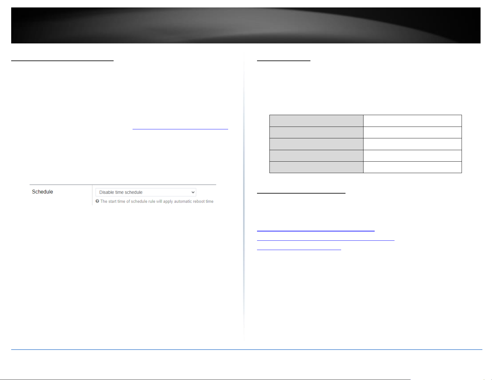
© Copyright 2023 TRENDnet. All Rights Reserved.
82
TRENDnet User’s Guide
TEW-929DRU
Scheduled automatic reboot
Management > Reboot > Setting
The scheduled automatic reboot feature allows you to set a daily or weekly schedule for
the router to initiate an automatic reboot in an attempt to resolve any connectivity
issues or intermittent problems that may occur with your device. Before using the
scheduled automatic reboot feature, please ensure your Time settings are configured
correctly and you have already created a time schedule for this function.
1. Log into your router management page (see “Access your router management page”
on page 6).
2. Click on Management, click on Reboot, and click on Setting tab.
3. Click the Automatic reboot by schedule drop-down list and select the schedule used
for the automatic device reboot function. Click Apply to save and commit the changes.
Console access
Using the includes RS-232 to RJ-45 console cable, you can access the router console
command line interface management through the console port for debugging and
troubleshooting if necessary.
You can access the command line interface management of router using the terminal
emulation program settings below.
Baud Rate (bps)
115200
Data Bits
8
Parity Bits
None
Stop Bits
1
Hardware Flow Control
Off
Command Line Interface
• The router firmware is based on OpenWRT which is based on Linux and
command usage can be refererenced from the web links below.
https://busybox.net/downloads/BusyBox.html
https://wiki.openwrt.org/doc/howto/user.beginner.cli
https://wiki.openwrt.org/doc/uci
Page 91
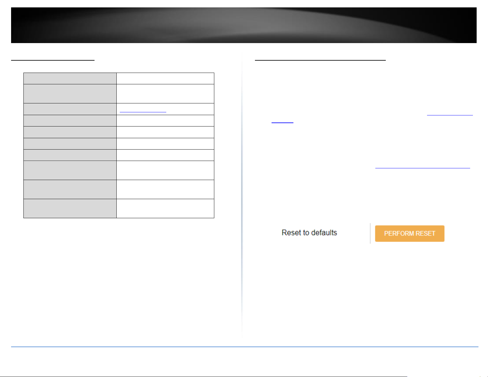
© Copyright 2023 TRENDnet. All Rights Reserved.
83
TRENDnet User’s Guide
TEW-929DRU
Router Default Settings
Administrator User Name
admin
Administrator Password
Please refer to sticker or device
label
Router Default URL
http://tew-929dru
Router IP Address
192.168.10.1
Router Subnet Mask
255.255.255.0
DHCP Server IP Range
192.168.10.101-192.168.199
Wireless 2.4GHz/5GHz1/5GHz2
Enabled
Wireless 2.4GHz/5GHz1/5GHz2
Network Name/Encryption
Please refer to sticker or device
label
Wireless 2.4GHz/5GHz1/5GHz2
Guest Network
Disabled
WAN1/WAN2 Mode
WAN1 Primary / WAN2 Secondary
Failover
Reset your router to factory defaults
Management > Firmware / Configuration
You may want to reset your router to factory defaults if you are encountering difficulties
with your router and have attempted all other troubleshooting.
There are two methods that can be used to reset your router to factory defaults.
• Reset Button – Located on the rear panel of your router, see “Product Hardware
Features”. Use this method if you are encountering difficulties with accessing
your router management page.
OR
• Router Management Page
1. Log into your router management page (see “Access your router management page”
on page 6).
2. Click on Management, then click on Firmware / Configuration.
3. Next to Reset to defaults, click Perform Reset. When prompted to confirm this action,
click OK.
4. Wait for the router to settings to factory default.
Page 92
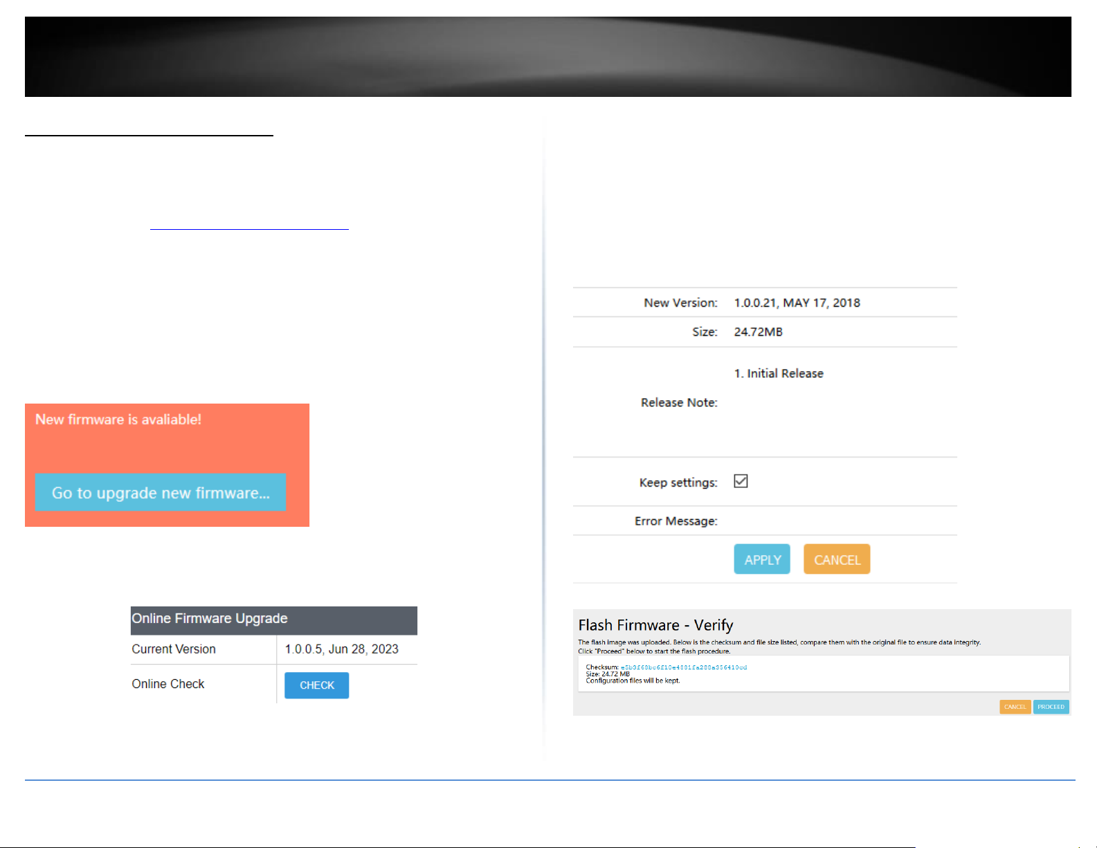
© Copyright 2023 TRENDnet. All Rights Reserved.
84
TRENDnet User’s Guide
TEW-929DRU
Upgrade your router firmware
Administrator > Backup / Flash Firmware
TRENDnet may periodically release firmware upgrades that may add features or fix
problems associated with your TRENDnet router model and version. To check if there is
a firmware upgrade available for your device, please check your TRENDnet model and
version using the link. http://www.trendnet.com/support
In addition, it is also important to verify if the latest firmware version is newer than the
one your router is currently running. To identify the firmware that is currently loaded on
your router, log in to the router, check the Administrator > Backup / Flash Firmware
under Online Firmware Upgrade or Status > Overview section under System.
Online Firmware Upgrade (requires router to be connected to Internet)
When your router has detected a new firmware available online, a notification will
appear at the top of the router management page. You can click the link or go to
Administrator > Backup / Flash Firmware
Under the Online Firmware Upgrade section, it will list the current firmware version
loaded on your router. Click Check to manually check if there is a new firmware
available online.
If a new firmware version is available, the details of the new version will appear such as
the firmware version, firmware file size, and release notes about the new firmware.
To start the online firmware upgrade process, click Apply. At the verification page, click
Proceed. Please wait for the online firmware upgrade procedure to complete
successfully.
Note: The Keep Settings option will upgrade the firmware version and preserve your
existing configuration settings. Unchecking the Keep Settings option will upgrade the
firmware version and reset the device to factory defaults.
Page 93
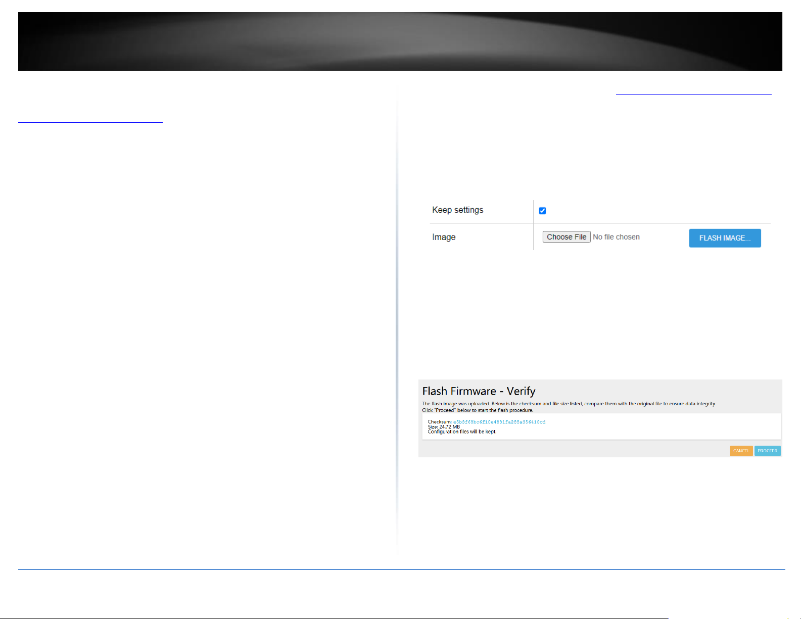
© Copyright 2023 TRENDnet. All Rights Reserved.
85
TRENDnet User’s Guide
TEW-929DRU
Manual Firmware Upgrade
1. If a firmware upgrade is available, check the router model on our website
http://www.trendnet.com/support and download the firmware to your computer.
2. Unzip the file to a folder on your computer.
Please note the following:
• Do not interrupt the firmware upgrade process. Do not turn off the device or
press the Reset button during the upgrade.
• If you are upgrade the firmware using a laptop computer, ensure that the laptop
is connected to a power source or ensure that the battery is fully charged.
• Disable sleep mode on your computer as this may interrupt the firmware upgrade
process.
• Do not upgrade the firmware using a wireless connection, only using a wired
network connection.
• Any interruptions during the firmware upgrade process may permanently
damage your router.
1. Log into your router management page (see “Access your router management page”
on page 6).
2. Click on Management and click on Firmware / Configuration.
3. Depending on your web browser, in the Flash new firmware image section, click
Browse or Choose File.
4. Navigate to the folder on your computer where the unzipped firmware file (.bin) is
located and select it.
Note: The Keep Settings option will upgrade the firmware version and preserve your
existing configuration settings. Unchecking the Keep Settings option will upgrade the
firmware version and reset the device to factory defaults.
5. At the verification page, click Proceed. Please wait for the online firmware upgrade
procedure to complete successfully.
Page 94
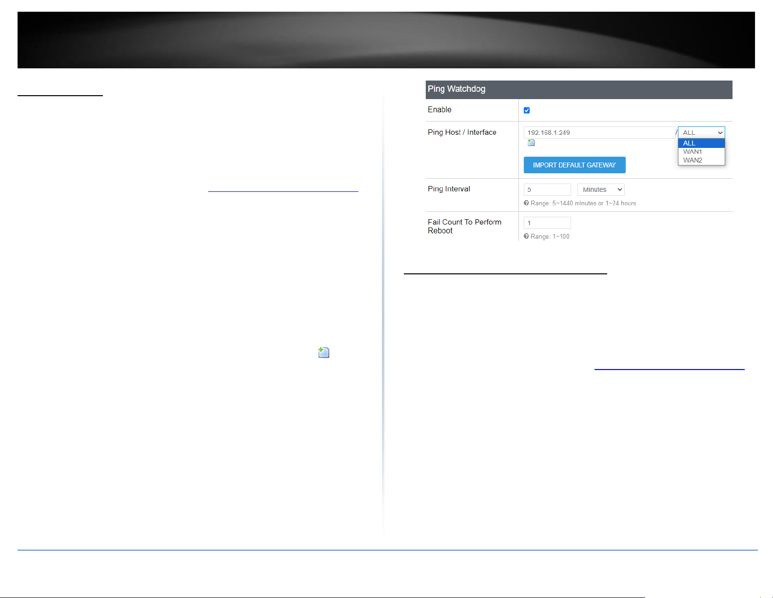
© Copyright 2023 TRENDnet. All Rights Reserved.
86
TRENDnet User’s Guide
TEW-929DRU
Ping Watchdog
Tools > Ping Watchdog
The Ping Watchdog feature allows you configure your router to monitor connectivity to
a specific host IP address. If connectivity is lost to the specified host IP address, the
router will automatically initiate a device reboot in an automatic attempt to re-establish
previously lost connectivity.
1. Log into your router management page (see “Access your router management page”
on page 6).
2. Click on Tools and click on Ping Watchdog.
3. Review the settings below. When complete, click Apply to save and commit your
changes.
Local Access Management
• Enable – Check this option to enable the ping watchdog feature.
• Ping Host / Interface – Enter the IP address to monitor and send ping requests to
check connectivity.
Note: You can additional host IP address entries to monitor by clicking .
o ALL – Check all local and WAN interfaces for the specified host IP
address.
o WAN1 – Check only the WAN1 interface for the specified host IP
address.
o WAN2 – Check only the WAN2 interface specified host IP address.
o Import Default Gateway – Clicking this option will automatically
attempt to copy both WAN interfaces default IP gateway to an
available entry.
• Ping Interval – Enter interval time for the router to send ping and connectivity
check. Ex: Setting the interval to 5 Minutes will configure to send a ping and check
connectivity every 5 mintes.
• Fail Count to Perform Reboot – Once ping/connectivity check fails, this sets the
maximum amount of attempts the router will attempt to check connectivity before
initiating an automatic reboot.
Check the router status information
Dashboard > Overview
You may want to check the system information of your router firmware, S/N, uptime,
available memory, active connection, WAN interface information, wireless interface
information, DHCP clients, connected wireless clients, dynamic DNS and active UPnP
entries.
1. Log into your router management page (see “Access your router management page”
on page 6).
2. Click on Status and click on Overview.
• System
o Hostname – Displays the currently assigned hostname of the router.
The name other network devices identify the router on the network.
o Firmware Version – Displays the currently loaded firmware version
and date.
o Local Time – Displays the current device time and date.
o Uptime – Displays the total amount of time the router has been up
and running without reboot.
Page 95
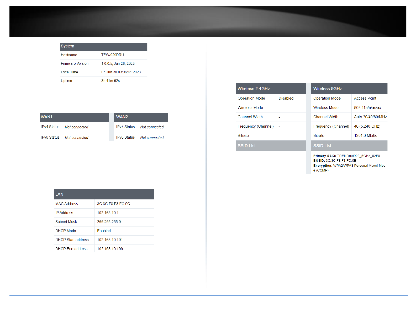
© Copyright 2023 TRENDnet. All Rights Reserved.
87
TRENDnet User’s Guide
TEW-929DRU
• WAN1 / WAN2
o IPv4 Status – Displays the current IPv4 status
o IPv6 Status – Displays the current IPv6 status
• LAN
o MAC Address – Displays the MAC address of the router
o IP Address – Displays the IP Address of the router
o Subnet Mask – Displays the subnet mask of the router
o DHCP Mode – Displays if DHCP mode is enabled
o DHCP Start address / DHCP End address – Displays the range of IP
addresses available for clients
• Wireless 2.4GHz / Wireless 5GHz
o Operation Mode – Displays the current operation mode for the
wireless band
o Wireless Mode – Displays the wireless mode of the wireless band
o Channel Width – Displays the channel width for the wireless band
o Frequency – Displays the current wireless channel (frequency) of the
wireless band
o Bitrate – Displays the max throughput of the wireless band
o SSID List – Displays the SSID, MAC Address, and the type of encryption
for the wireless band
CPU & Memory Utilization
• CPU Used – Displays how much of the CPU is being used
• CPU Idle – Displays the how much of the CPU is being idle
• Memory Total – Displays the total amount of memory in the router
• Memory Free – Displays the total amount memory that is not being unsed
• Memory Used – Displays the total amount of memory being used
Page 96
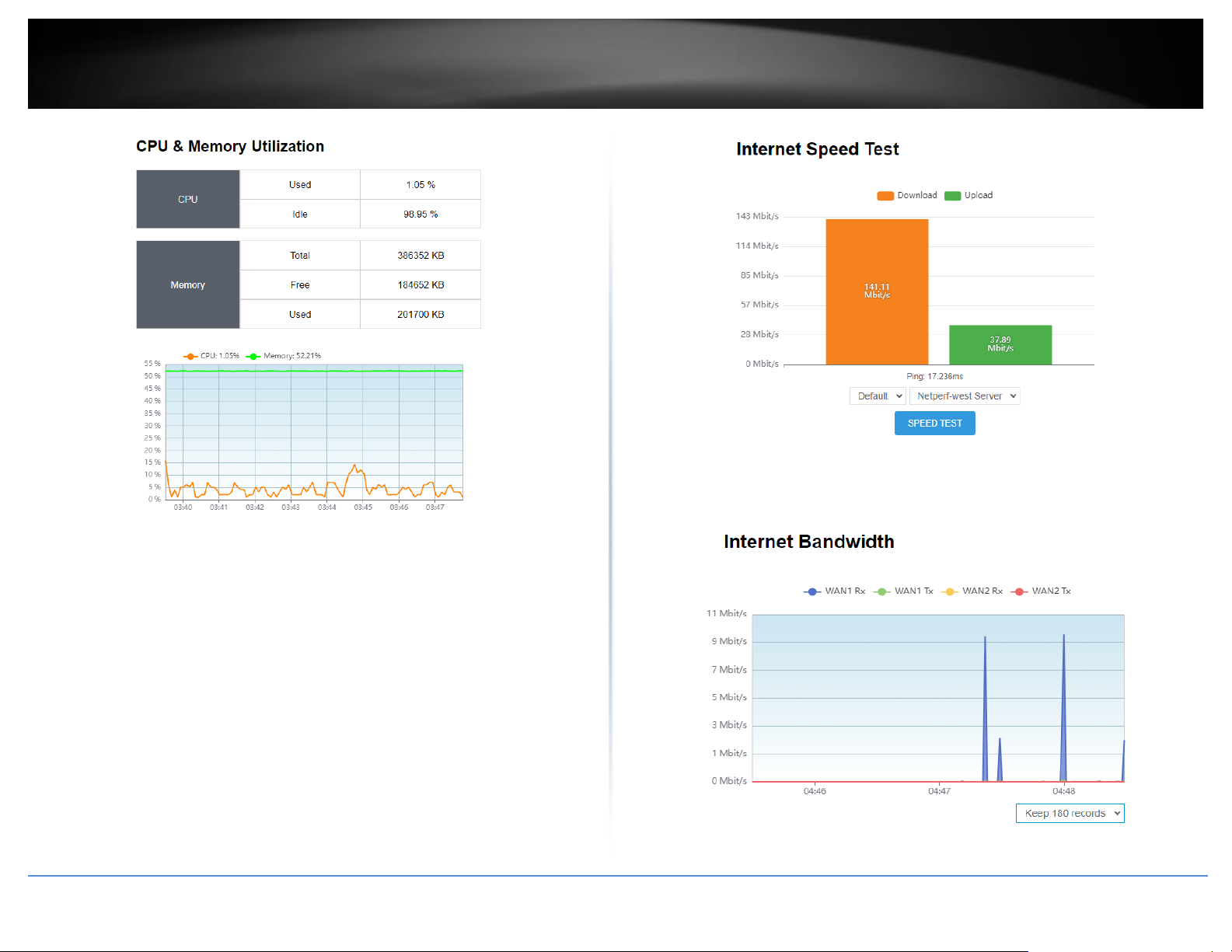
© Copyright 2023 TRENDnet. All Rights Reserved.
88
TRENDnet User’s Guide
TEW-929DRU
Internet Speed Test
• Interface – Select the WAN interface to conduct testing
• Default – Uses the internal loopback interface to conduct the connectivity test
• WAN1/WAN2 – You can select either WAN1 or WAN2 to conduct the speed
test through a specific WAN interface.
• Server – Select the server to run a speed test with
Internet Speed Test
Displays on a graph the amount of traffic being passed through from the ISP.
Page 97
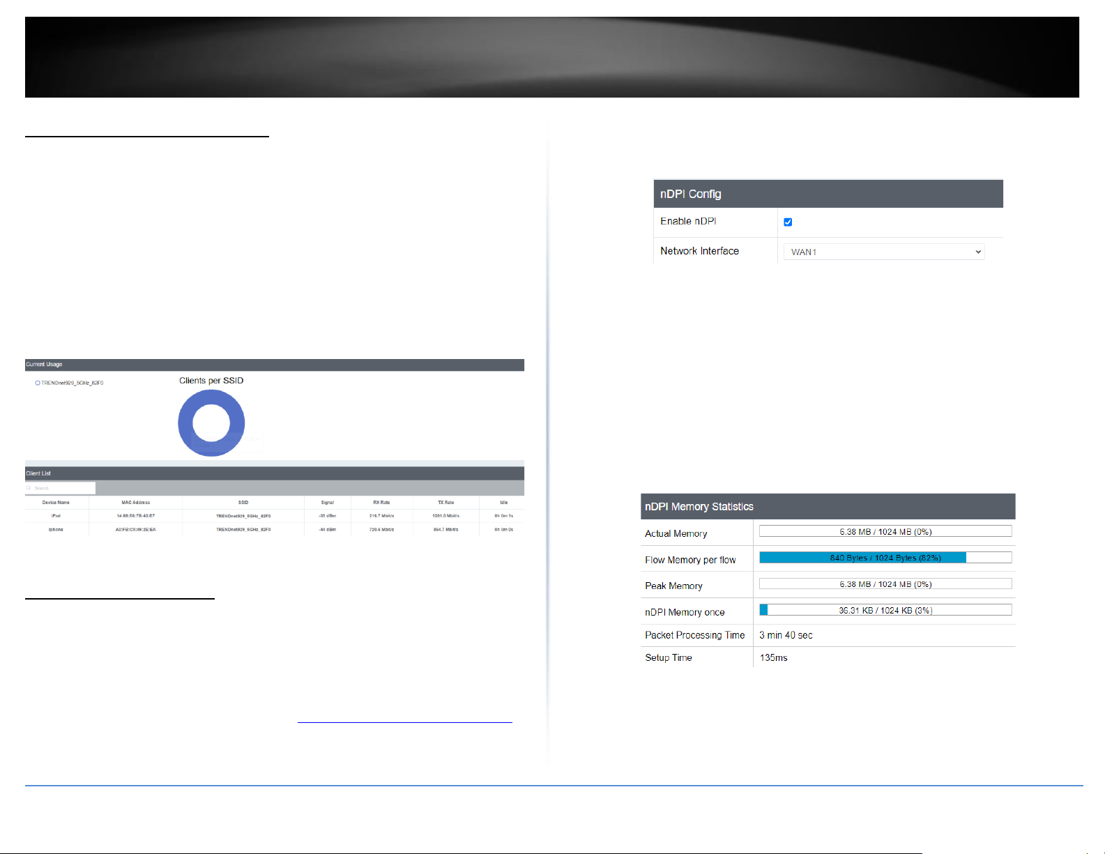
© Copyright 2023 TRENDnet. All Rights Reserved.
89
TRENDnet User’s Guide
TEW-929DRU
Check WiFi status information
Dashboard > Wireless 2.4GHz / Wireless 5GHz
Wireless Status Information
• Device Name – Displays the name of the device connected to the wireless band
• MAC Address – Displays the MAC address of the device connected to the
wireless band
• Signal – Displays the signal strength
• Rx Rate / Tx Rate – Displays the connection rate for Rx/Tx
• Idle – Displays the time the device is idled on the wireless band
Deep Packet Inspection
Dashboard > nDPI Statistics
Deep packet inspection is a feature that allows the router to inspect the type of data
being passed through the network.
1. Log into your router management page (see “Access your router management page”
on page 6).
2. Click on Dashboard, then click on nDPI Statistics
3. Click Enable nDPI to enable this feature
4. Select the Network Interface for nDPI to inspect
nDPI Memory Statistics
• Actual Memory – The current amount of memory utilization for nDPI and
typically the same as Peak Memory.
• Flow Memory per flow – The total amount of memory allocated per flow.
• Peak Memory – The maximum amount of memory used for nDPI in the current
session.
• nDPI Memory once – Memory utilized for the nDPI application.
• Packet Processing Time –Displays length of time nDPI has been enabled
• Setup Time – Displays the latency
Traffic Statistics
• Ethernet bytes – Displays the total data that has passed through in Bytes
• Discarded bytes – Displays the amount of discarded bytes
Page 98
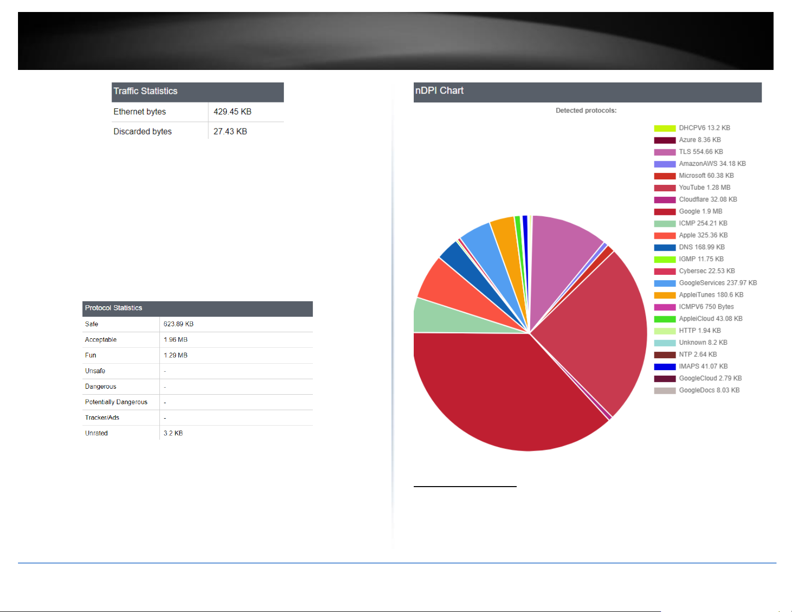
© Copyright 2023 TRENDnet. All Rights Reserved.
90
TRENDnet User’s Guide
TEW-929DRU
Protocol Statistics
• Safe – Displays the amount of data that was safe
• Acceptable – Displays the amount of data that was acceptable
• Fun – Displays the amount of data used for various social media, media
streaming services, gaming, and chat.
• Unsafe – Displays the amount of data that was unsafe
• Dangerous – Displays the amount of data that was dangerous
• Potentially Dangerous – Displays the amount of data that was Potentially
Dangerous
• Tracker/Ads – Displays the data that passed through were ads or trackers
• Unrated – Displays the ads that were unrated
nDPI Chart
This chart shows the break down of the types of data being processed through the
selected Network Interface, as well as the amount of data in bytes. Data is refreshed
every 15 seconds.
Real-Time Graphs
Dashboard > Real-Time Graphs
This section displays the device real-time CPU load, traffic load, and connection/session
information.
Page 99
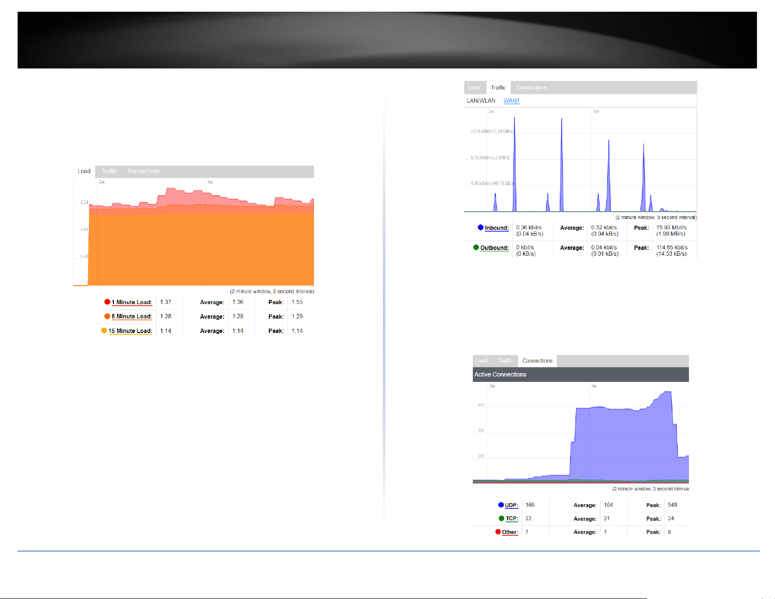
© Copyright 2023 TRENDnet. All Rights Reserved.
91
TRENDnet User’s Guide
TEW-929DRU
CPU Load
This chart shows the load of the CPU in 1 minute, 5 minutes, and 15 minutes intervals.
• Red graph: Displays the CPU load in the last 1 minute
• Orange graph: Displays the CPU load in the last 5 minutes
• Yellow graph: Displays the CPU load in the last 15 minutes
Traffic Load
This chart shows the real-time traffic load
• Blue graph: Displays the inbound traffic
• Green graph: Displays the outbound traffic
Traffic Load
This chart shows the connection and session information
• Blue graph: Displays the connections with UDP protocol
• Green graph: Displays the connections with TCP protocol
• Red graph: Displays the connections that do not use UDP or TCP protocol
Page 100
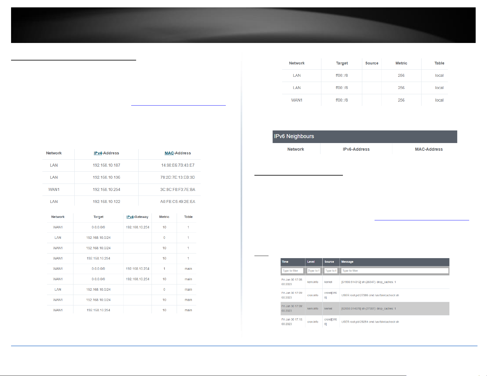
© Copyright 2023 TRENDnet. All Rights Reserved.
92
TRENDnet User’s Guide
TEW-929DRU
View routing table and ARP entries
System > Routes / ARP
You may want to check the current routing table and ARP entry information for
troubleshooting or monitoring purposes.
1. Log into your router management page (see “Access your router management page”
on page 8).
2. Click on System and click on Routes / ARP.
• ARP – Displays the router ARP table.
• Active IPv4-Routes – Displays the current IPv4 active routing table.
• Active IPv6-Routes – Displays the current IPv6 active routing table.
• IPv6 Neighbors – Displays currently discovered/detected IPv6 neighbor
devices.
View your router logging
System > System Log
Your router system log can be used to obtain activity information on the functionality of
your router or for troubleshooting purposes.
1. Log into your router management page (see “Access your router management page”
on page 8).
2. Click on System and click on System Log.
Note: The router system log will display the most recent entries in the list.
 Loading...