

Page 1
TRENDnet User’s Guide
Cover Page
Page 2

TRENDnet User’s Guide
Table of Contents
Product Overview ........................................................................... 1
TEW-823DAP .................................................................................................................. 1
Features ......................................................................................................................... 1
Product Hardware Features........................................................................................... 2
Application Diagram ...................................................................................................... 3
Product Overview ........................................................................... 4
TEW-923DAP .................................................................................................................. 4
Features ......................................................................................................................... 4
Product Hardware Features........................................................................................... 5
Basic ............................................................................................................................. 17
Wireless Profile ............................................................................................................ 19
MAC filter (TEW-823DAP) ............................................................................................ 19
Wireless MAC Filter (TEW-923DAP / TEW-925DAP) .................................................... 20
Band Steering .............................................................................................................. 21
Roaming Support (802.11k / 802.11r) ......................................................................... 21
Change your IP address ............................................................................................... 21
Reboot Schedule (TEW-823DAP) ................................................................................. 22
Schedule (TEW-923DAP/TEW-925DAP)....................................................................... 22
Configure Spanning Tree ............................................................................................. 23
Set date and time ........................................................................................................ 23
Table of contents
Product Overview ........................................................................... 6
TEW-925DAP .................................................................................................................. 6
Features ......................................................................................................................... 7
Product Hardware Features........................................................................................... 8
Getting Started .............................................................................................................. 9
Steps to improve wireless connectivity ....................................................................... 10
Connect wireless devices to your access point ............................................................ 10
Configuration ................................................................................ 11
Wireless Networking and Security ................................................. 12
How to choose the type of security for your wireless network .................................. 12
Secure your wireless network ..................................................................................... 13
Connect wireless devices using WPS ........................................................................... 15
Advanced configuration ................................................................ 16
Access the management page ..................................................................................... 16
Operating Modes ......................................................................................................... 16
Access Point .................................................................................. 17
Daylight Saving Time ................................................................................................... 24
NTP .............................................................................................................................. 24
Manual ......................................................................................................................... 24
Management VLAN...................................................................................................... 24
Wireless Bandwidth Control ........................................................................................ 25
Enable SNMP ............................................................................................................... 25
SSH Management ........................................................................................................ 26
LED Controls ................................................................................................................ 26
LLDP (TEW-923DAP / TEW-925DAP)............................................................................ 26
UPnP ............................................................................................................................ 27
Bonjour ........................................................................................................................ 27
Gateway Monitor ........................................................................................................ 27
Repeater ....................................................................................... 28
Basic ............................................................................................................................. 28
Scan for wireless networks .......................................................................................... 29
Advanced wireless settings ......................................................................................... 30
© Copyright 2023 TRENDnet. All Rights Reserved.
i
Page 3

TRENDnet User’s Guide
Advanced Wireless............................................................................................. 30
Client Limit ......................................................................................................... 30
Maintenance & Monitoring ........................................................... 31
Administration ............................................................................................................. 31
Timeout........................................................................................................................ 31
Device Name ................................................................................................................ 31
Reset to factory defaults ............................................................................................. 31
Backup and restore your configuration settings ......................................................... 32
Restart (Reboot) access point ...................................................................................... 32
Upgrade your firmware ............................................................................................... 33
Configure log................................................................................................................ 33
Diagnostics ................................................................................................................... 33
Check system information ........................................................................................... 34
Check connected wireless clients ................................................................................ 35
System Log ................................................................................................................... 35
Table of contents
Hardware Features and Specifications ........................................................................ 36
Indoor Access Point Software Specifications ............................................................... 39
Troubleshooting ............................................................................ 40
Appendix ...................................................................................... 41
© Copyright 2023 TRENDnet. All Rights Reserved.
ii
Page 4
TRENDnet User’s Guide
Product Overview
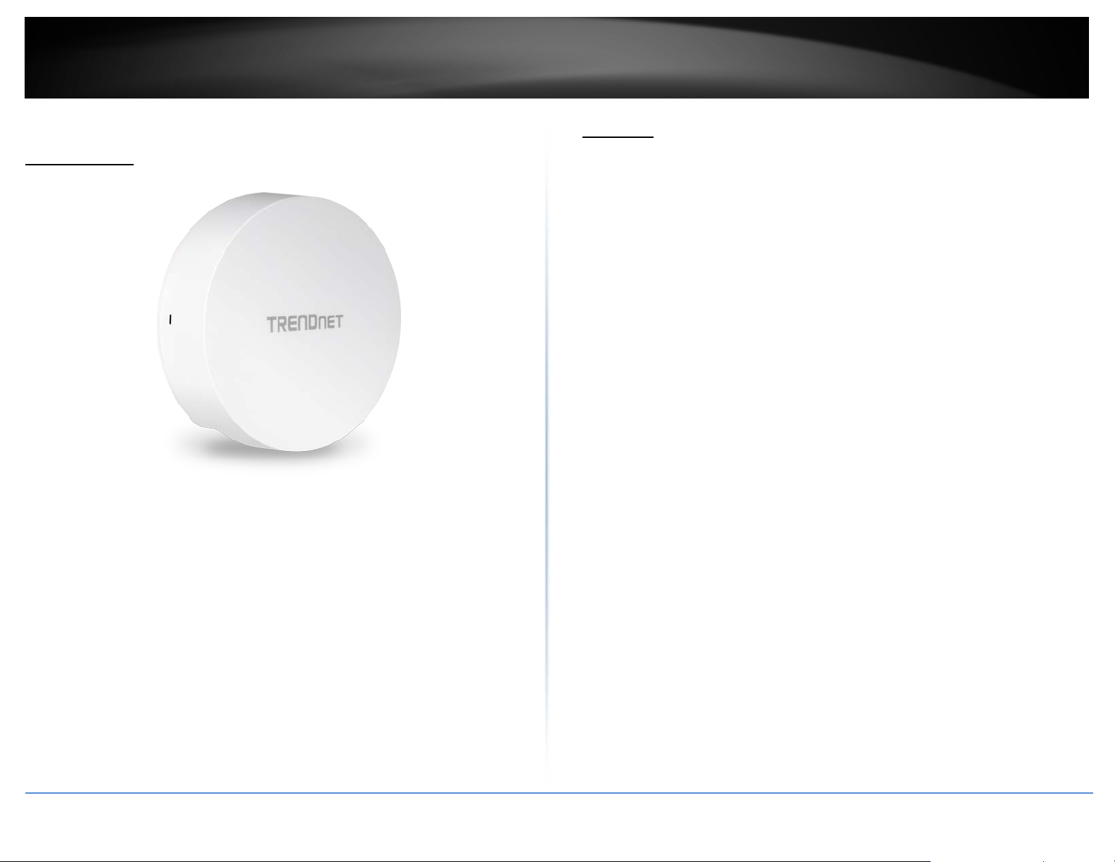
TEW-823DAP
Features
TRENDnet’s high-performance AC1300 Dual Band Indoor Wireless PoE Access Point,
model TEW-823DAP, supports Access Point (AP) and Repeater modes. This wireless
indoor access point generates concurrent 867Mbps WiFi AC and 400Mbps WiFi N
networks. MU-MIMO technology processes multiple data streams simultaneously,
increasing real-time WiFi performance when multiple devices access the network. The
wireless access point features access control, bandwidth control, and band steering. The
low-profile housing design blends into most environments, and includes a convenient
wall / ceiling mounting plate.
Indoor Wireless Access Points
Concurrent Dual Band
AC1300: concurrent 867Mbps WiFi AC + 400Mbps WiFi N bands
Power over Ethernet (PoE)
Saves installation time and setup costs with gigabit PoE support
TEW-823DAP
Package Contents
In addition to your access point, the package includes:
• TEW-823DAP
• 1.64 ft. (0.5 m) network cable
• Quick Installation Guide
• Mounting plates
If any package contents are missing or damaged, please contact the retail store, online
retailer, or reseller/distributor from which the product was purchased.
WiFi Operation Modes
Supports Access Point (AP) and Repeater modes
Gigabit Port
Gigabit PoE LAN port maintains a high-performance connection to the wired network
Wireless Coverage
Extended wireless coverage with MU-MIMO antenna technology
MU-MIMO Performance
MU-MIMO technology enables the access point to process multiple data streams
simultaneously, and increases real-time WiFi performance
© Copyright 2023 TRENDnet. All Rights Reserved.
1
Page 5
PWR
TRENDnet User’s Guide
Band Steering
Band steering alleviates network congestion by automatically directing wireless devices
from the 2.4GHz band to the 5GHz band
Product Hardware Features
Low-profile housing
Indoor Wireless Access Points
Multiple SSIDs
Create up to 8 SSIDs per band (16 total)
Encrypted Wireless
Support for wireless encryption of up to WPA3
Low Profile
Low-profile housing design blends into most environments
Mounting Plate
Wall / Ceiling mounting plate
*Maximum wireless signal rates are referenced from IEEE 802.11 theoretical
specifications. Actual data throughput and coverage will vary depending on
interference, network traffic, building materials and other conditions.
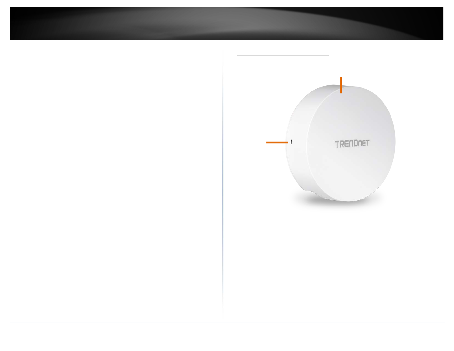
• PWR: This indicator turns blue when the device is powered.
© Copyright 2023 TRENDnet. All Rights Reserved.
2
Page 6
Gigabit PoE Port
TRENDnet User’s Guide
Indoor Wireless Access Points
Application Diagram
Power port
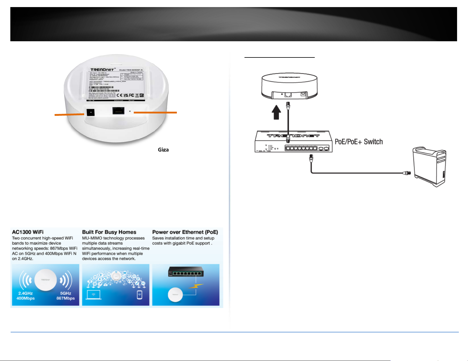
• Gigabit PoE port: Plug an Ethernet cable (also called network cables) from
your access point to your router and wired network devices. The Gigabit port
complies with standard 802.3af/at PoE/PoE+ so you can connect to connect the AP
to a PoE switch or injector that complies with 802.3af/at.
• Power port (optional): If you are not using PoE to power the AP, you can connect
the power adapter from your access point power port to an available power outlet.
• Reset button: Use a sharp tool to press and hold this button for 15 seconds to
reset the access point.
Reset button
© Copyright 2023 TRENDnet. All Rights Reserved.
3
Page 7
TRENDnet User’s Guide
Product Overview
TEW-923DAP
Features
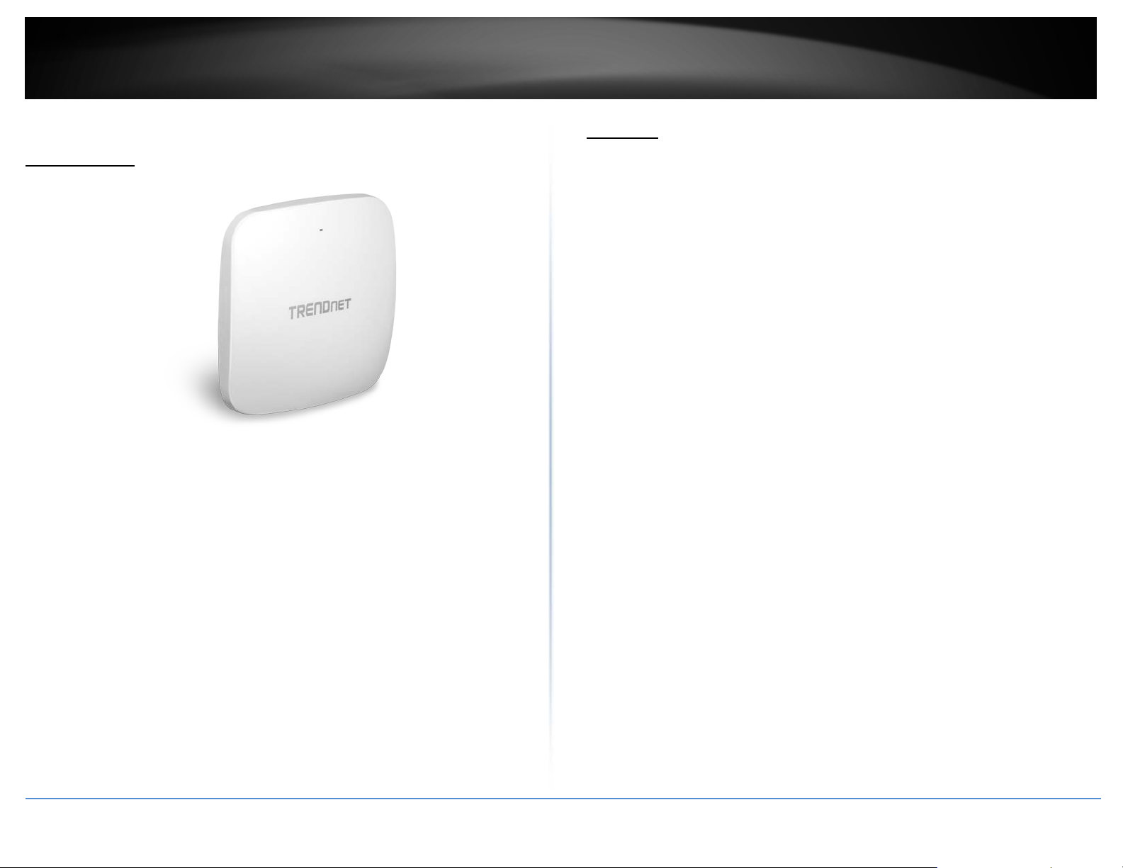
TRENDnet’s high-performance AX3000 Dual Band WiFi 6 PoE+ Access Point, model TEW923DAP, features two concurrent WiFi bands to maximize networking speeds with the
latest WiFi 6 technology. The two separate high-speed WiFi 6 bands provide speeds up
to 2402Mbps on the 5GHz band and 573Mbps on the 2.4GHz band. The access point
also supports Access Point (AP) and Repeater modes.
Faster speeds are possible on this WiFi 6 access point with 1024-QAM, OFDMA, and MUMIMO technologies. MU-MIMO technology processes multiple data streams
simultaneously, increasing real-time WiFi performance when multiple devices access the
network. The wireless access point features access control, bandwidth control, and band
steering. The low-profile housing design blends into most environments, and includes a
convenient wall / ceiling mounting plate.
Indoor Wireless Access Points
Concurrent Dual Band
AX3000: concurrent 2402Mbps on 5GHz band + 573Mbps on 2.4GHz band
TEW-923DAP
Power over Ethernet (PoE+)
Package Contents
In addition to your access point, the package includes:
• TEW-923DAP
• 1.64 ft. (0.5 m) network cable
• Quick Installation Guide
• Mounting plates
If any package contents are missing or damaged, please contact the retail store, online
retailer, or reseller/distributor from which the product was purchased.
Saves installation time and setup costs with 2.5GbE PoE+ support
WiFi Operation Modes
Supports Access Point (AP) and Repeater modes
MU-MIMO & OFDMA Performance
MU-MIMO technology enables the access point to process multiple data streams
simultaneously along with WiFi 6 OFDMA technology to increase real-time WiFi
performance
Band Steering
Band steering alleviates network congestion by automatically directing wireless devices
from the 2.4GHz band to the 5GHz band
© Copyright 2023 TRENDnet. All Rights Reserved.
4
Page 8
PWR
TRENDnet User’s Guide
WiFi Traffic Shaping
Manage traffic allocation on the WiFi 6 access point per SSID for each band separately
Encrypted Wireless
Support for wireless encryption of up to WPA3
Product Hardware Features
Indoor Wireless Access Points
Low-profile housing
Multiple SSIDs
Create up to 8 SSIDs per band (16 total)
2.5GBASE-T PoE+ Port
2.5GBASE-T PoE+ LAN port maintains a high-performance connection to the wired
network
LED Control
LED control reduces product visibility by disabling the LED indicator
Low Profile
Low-profile housing design blends into most environments
Mounting Plate
Wall / Ceiling mounting plate
*Maximum wireless signal rates are referenced from IEEE 802.11 theoretical
specifications. Actual data throughput and coverage will vary depending on
interference, network traffic, building materials and other conditions.
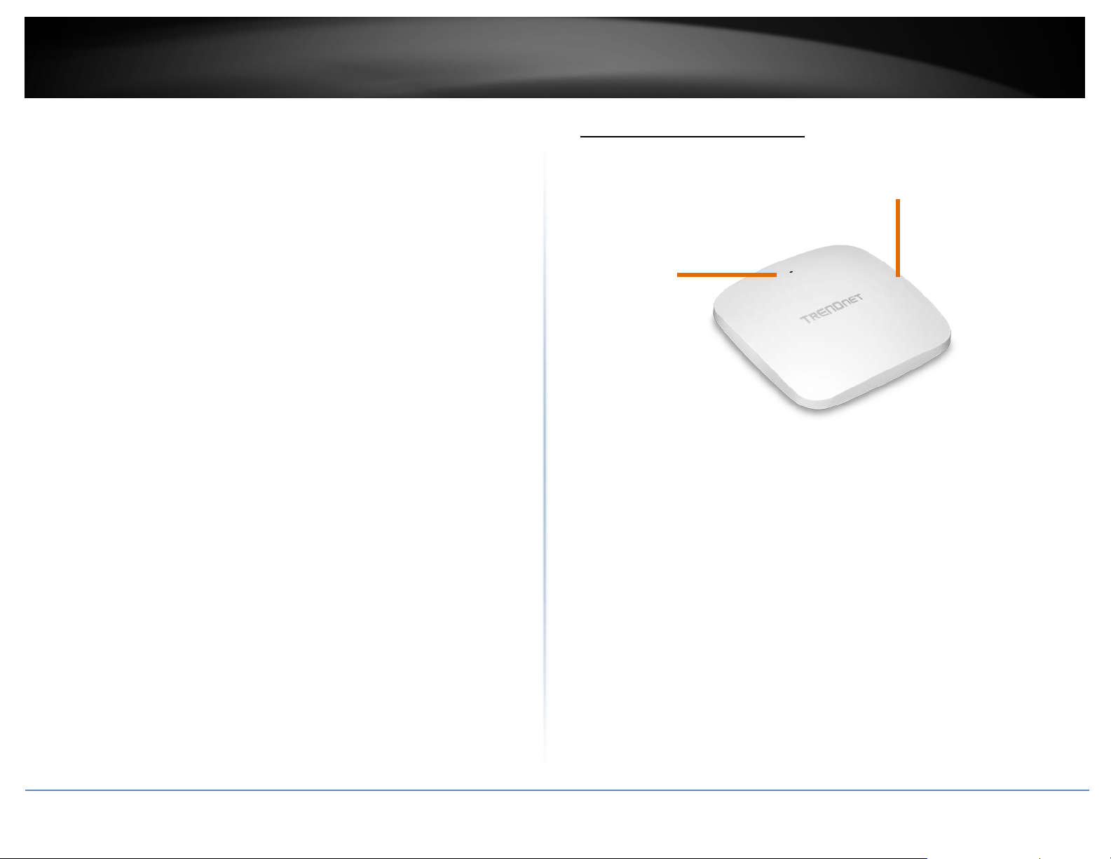
• PWR: This indicator turns blue when the device is powered.
© Copyright 2023 TRENDnet. All Rights Reserved.
5
Page 9
2.5GBASE-T PoE+ Port
TRENDnet User’s Guide
Indoor Wireless Access Points
Product Overview
TEW-925DAP
Power port
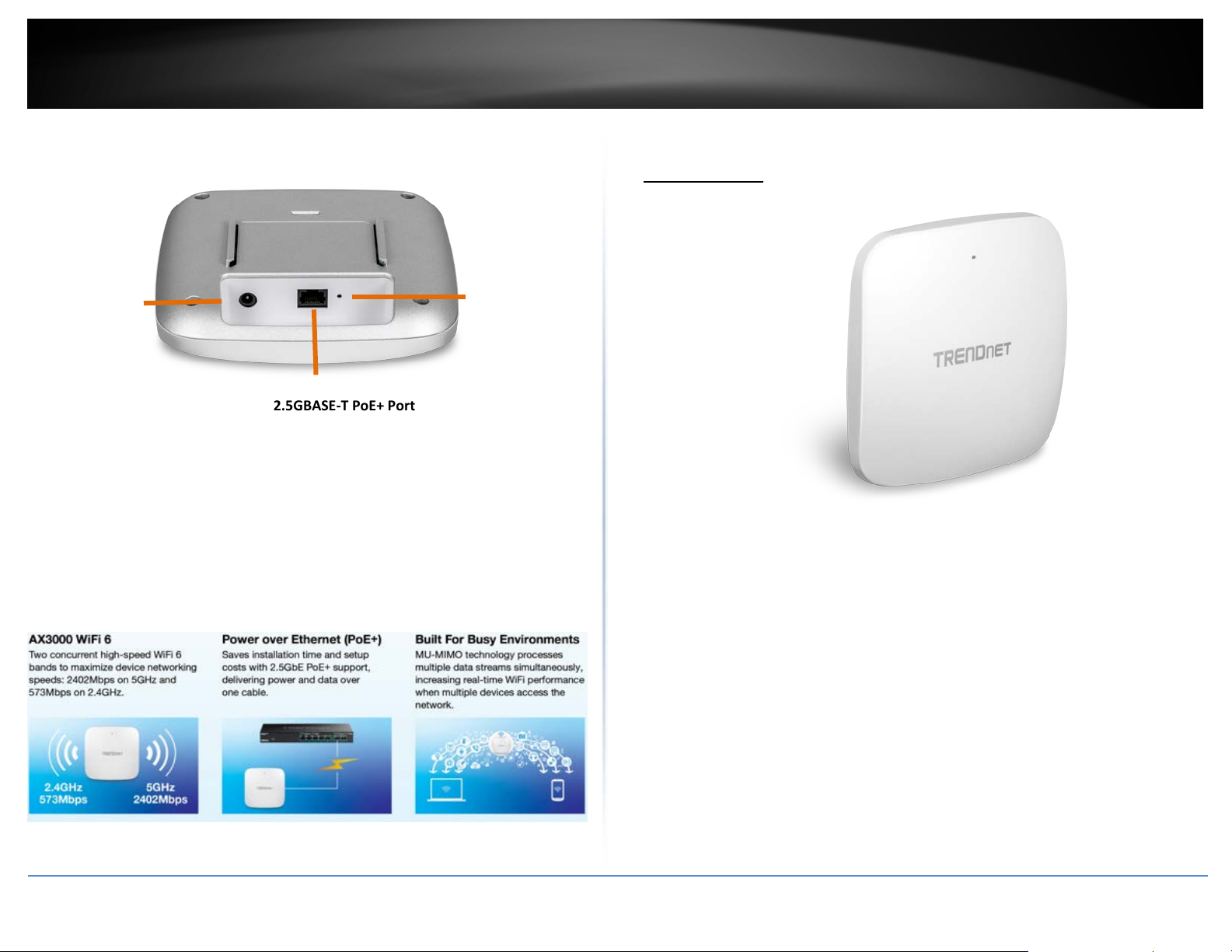
• 2.5GBASE-T PoE+ port: Plug an Ethernet cable (also called network cables) from
your access point to your router and wired network devices. The Gigabit port
complies with standard 802.3af/at PoE/PoE+ so you can connect to connect the AP
to a PoE switch or injector that complies with 802.3af/at.
• Power port (optional): If you are not using PoE to power the AP, you can connect
the power adapter from your access point power port to an available power outlet.
• Reset button: Use a sharp tool to press and hold this button for 15 seconds to
reset the access point.
Reset button
TEW-925DAP
Package Contents
In addition to your access point, the package includes:
• TEW-925DAP
• 1.64 ft. (0.5 m) network cable
• Quick Installation Guide
• Mounting plates
If any package contents are missing or damaged, please contact the retail store, online
retailer, or reseller/distributor from which the product was purchased.
© Copyright 2023 TRENDnet. All Rights Reserved.
6
Page 10

TRENDnet User’s Guide
Features
TRENDnet’s high-performance AX5400 Dual Band WiFi 6 PoE+ Access Point, model TEW925DAP, features two concurrent WiFi bands to maximize networking speeds with the
latest WiFi 6 technology. The two separate high-speed WiFi 6 bands provide speeds up
to 4804Mbps on the 5GHz band and 573Mbps on the 2.4GHz band. The WiFi 6 access
point also supports Access Point (AP) and Repeater modes.
Faster speeds are possible on this WiFi 6 access point with 1024-QAM, OFDMA, and MUMIMO technologies. MU-MIMO technology processes multiple data streams
simultaneously, increasing real-time WiFi performance when multiple devices access the
network. The wireless access point features access control, bandwidth control, and band
steering. The low-profile housing design blends into most environments, and includes a
convenient wall / ceiling mounting plate.
Concurrent Dual Band
AX5400: concurrent 4804Mbps on 5GHz band + 573Mbps on 2.4GHz band
Power over Ethernet (PoE+)
Saves installation time and setup costs with 2.5GbE PoE+ support
WiFi Operation Modes
The 802.11ax access points supports Access Point (AP) and Repeater modes
MU-MIMO & OFDMA Performance
MU-MIMO technology enables the WiFi 6 access point to process multiple data streams
simultaneously along with WiFi 6 OFDMA technology to increase real-time WiFi
performance
Band Steering
Band steering alleviates network congestion by automatically directing wireless devices
from the 2.4GHz band to the 5GHz band
WiFi Traffic Shaping
Manage traffic allocation on the WiFi 6 access point per SSID for each band separately
Encrypted Wireless
Support for wireless encryption of up to WPA3
Multiple SSIDs
Create up to 8 SSIDs per band (16 total)
2.5GBASE-T PoE+ Port
2.5GBASE-T PoE+ LAN port maintains a high-performance connection to the wired
network
LED Control
LED control on the WiFi 6 access point reduces product visibility by disabling the LED
indicator
Low Profile
Low-profile housing design blends into most environments
Mounting Plate
The WiFi 6 access points includes a wall / ceiling mounting plate
*Maximum wireless signal rates are referenced from IEEE 802.11 theoretical
specifications. Actual data throughput and coverage will vary depending on
interference, network traffic, building materials and other conditions.
Indoor Wireless Access Points
© Copyright 2023 TRENDnet. All Rights Reserved.
7
Page 11
2.5GBASE-T PoE+ Port
PWR
TRENDnet User’s Guide
Indoor Wireless Access Points
Product Hardware Features
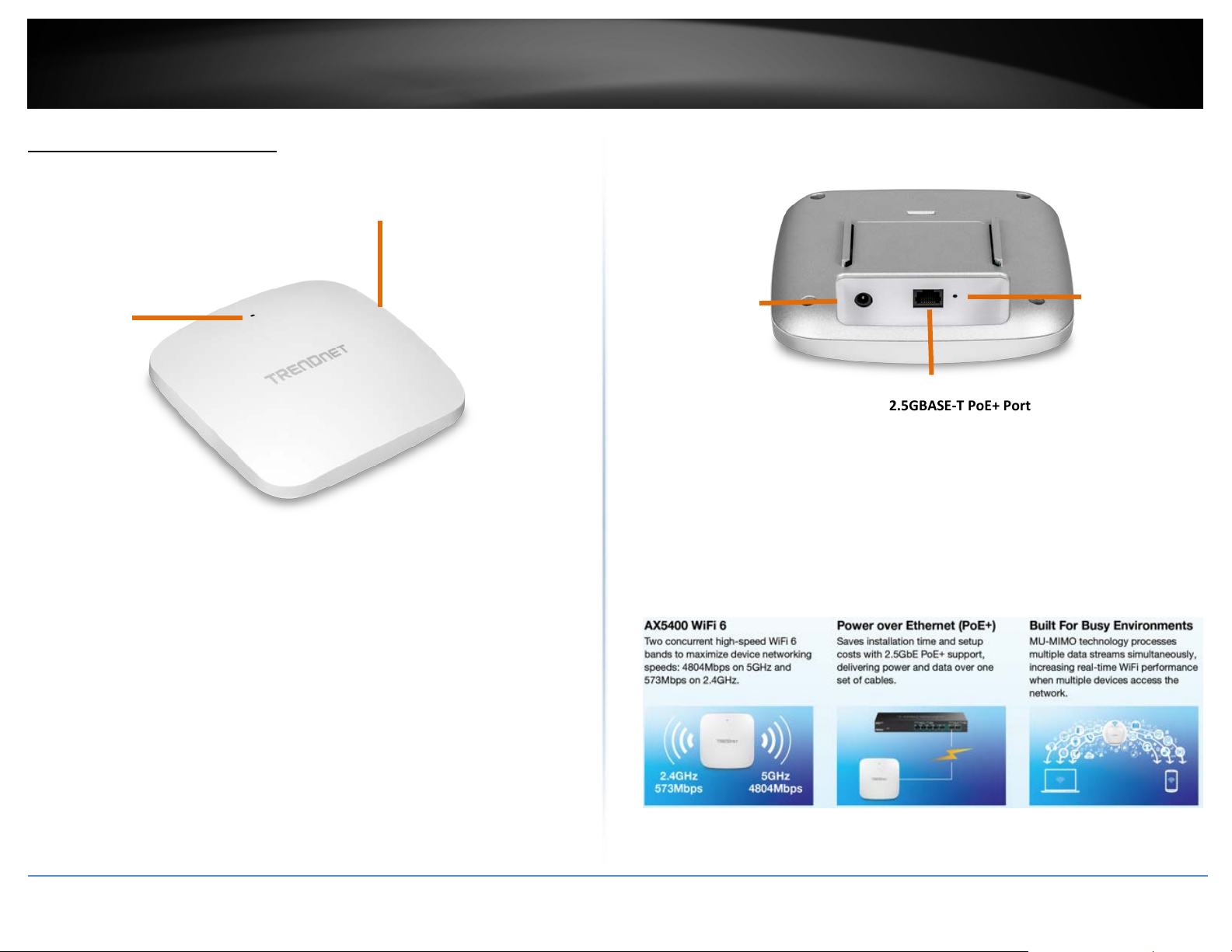
• PWR: This indicator turns blue when the device is powered.
Low-profile housing
Power port
• 2.5GBASE-T PoE+ port: Plug an Ethernet cable (also called network cables) from
your access point to your router and wired network devices. The Gigabit port
complies with standard 802.3af/at PoE/PoE+ so you can connect to connect the AP
to a PoE switch or injector that complies with 802.3af/at.
• Power port (optional): If you are not using PoE to power the AP, you can connect
the power adapter from your access point power port to an available power outlet.
• Reset button: Use a sharp tool to press and hold this button for 15 seconds to
reset the access point.
Reset button
© Copyright 2023 TRENDnet. All Rights Reserved.
8
Page 12
TRENDnet User’s Guide
Getting Started
For a typical wireless setup at home or office when using the access point in AP mode,
please do the following:
Installation
1. Connect the power adapter to the power port of the access point. Or simply plug an
Ethernet cable on the access point to a PoE (Power over Ethernet) switch that
connects to your router or network.
2. If using the power adapter, plug an Ethernet cable to the access point and plug the
other end to your router or network.
3. Verify that all LEDs are on.
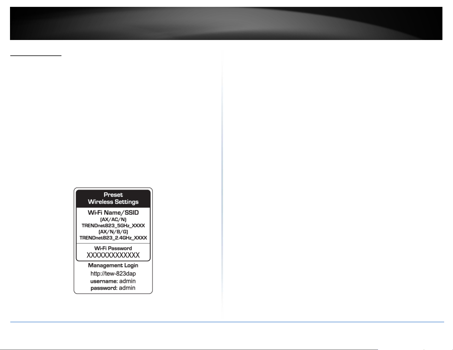
4. For your security, each access point comes pre-encrypted with a unique WiFi Name
(SSID) and WiFi Password. You can find your device's SSID and WiFi password on the
white labels located on the device. Use this information to connect to the access
point.
Note: The white label below may be different than the label included with your access
point.
5. Verify your connection to you network by accessing the Internet. For advanced
configuration continue to the advanced sections of the user manual.
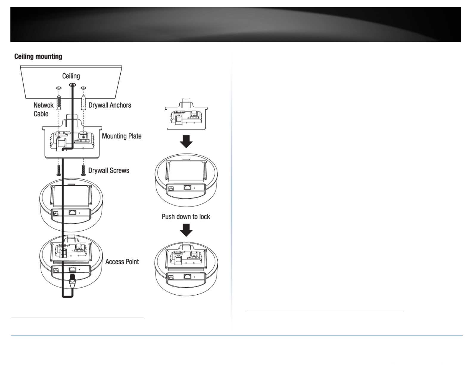
Mounting device
To mount the access point, first route the network cable through the largest opening in
the mounting plate and install the mounting plate to the desired wall or ceiling using the
included drywall anchors and screws. Install the mounting plate with the correct
orientation. After the mounting plate is properly installed, connect the network cable to
the network LAN port of the access point, align the access point mounting holes with
the mounting plate clips and slide the bracket into the access point to lock into place
Indoor Wireless Access Points
© Copyright 2023 TRENDnet. All Rights Reserved.
9
Page 13
TRENDnet User’s Guide
There are a number of factors that can impact the range of wireless devices. Follow
these tips to help improve your wireless connectivity:
• Keep the number of obstructions to a minimum. Each obstruction can reduce the
range of a wireless device. Position the wireless devices in a manner that will
minimize the amount of obstructions between them.
a. For the widest coverage area, install your router near the center of your home, and
near the ceiling, if possible.
b. Avoid placing the access point on or near metal objects (such as file cabinets and
metal furniture), reflective surfaces (such as glass or mirrors), and masonry walls.
c. Any obstruction can weaken the wireless signal (even non-metallic objects), so the
fewer obstructions between the router and the wireless device, the better.
d. Place the access point in a location away from other electronics, motors, and
fluorescent lighting.
e. Many environmental variables can affect the router’s performance, so if your
wireless signal is weak, place the access point in several locations and test the signal
strength to determine the ideal position.
• Building materials can have a large impact on your wireless signal. In an indoor
environment, try to position the wireless devices so that the signal passes through
less dense material such as dry wall. Dense materials like metal, solid wood, glass or
even furniture may block or degrade the signal.
• Antenna orientation can also have a large impact on your wireless signal. Use the
wireless adapter’s site survey tool to determine the best antenna orientation for your
wireless devices.
• Interference from devices that produce RF (radio frequency) noise can also impact
your signal. Position your wireless devices away from anything that generates RF
noise, such as microwaves, radios and baby monitors.
If possible, upgrade wireless network interfaces (such as wireless cards in computers)
from older wireless standards to 802.11n. If a wirelessly networked device uses an older
standard, the performance of the entire wireless network may be slower. If you are still
experiencing low or no signal, consider repositioning the wireless devices or installing
additional access points.
Indoor Wireless Access Points
Connect wireless devices to your access point
Steps to improve wireless connectivity
© Copyright 2023 TRENDnet. All Rights Reserved.
A variety of wireless network devices can connect to your wireless network such as:
• Gaming Consoles
10
Page 14
TRENDnet User’s Guide
• Internet enabled TVs
• Network media players
• Smart Phones
• Wireless Laptop computers
• Wireless IP cameras
Each device may have its own software utility for searching and connecting to available
wireless networks, therefore, you must refer to the User’s Manual/Guide of your
wireless client device to determine how to search and connect to this router’s wireless
network.
See the “Appendix
network.
” on page 63 for general information on connecting to a wireless
Configuration
Note: The access point’s default management page http://192.168.10.100 is accessed
through the use of your Internet web browser (e.g. Internet Explorer, Firefox, Chrome,
Safari, and Opera) and will be referenced frequently in this User’s Guide.
Before accessing the web-based management page, configure the IP address and
subnet mask of your computer to the following:
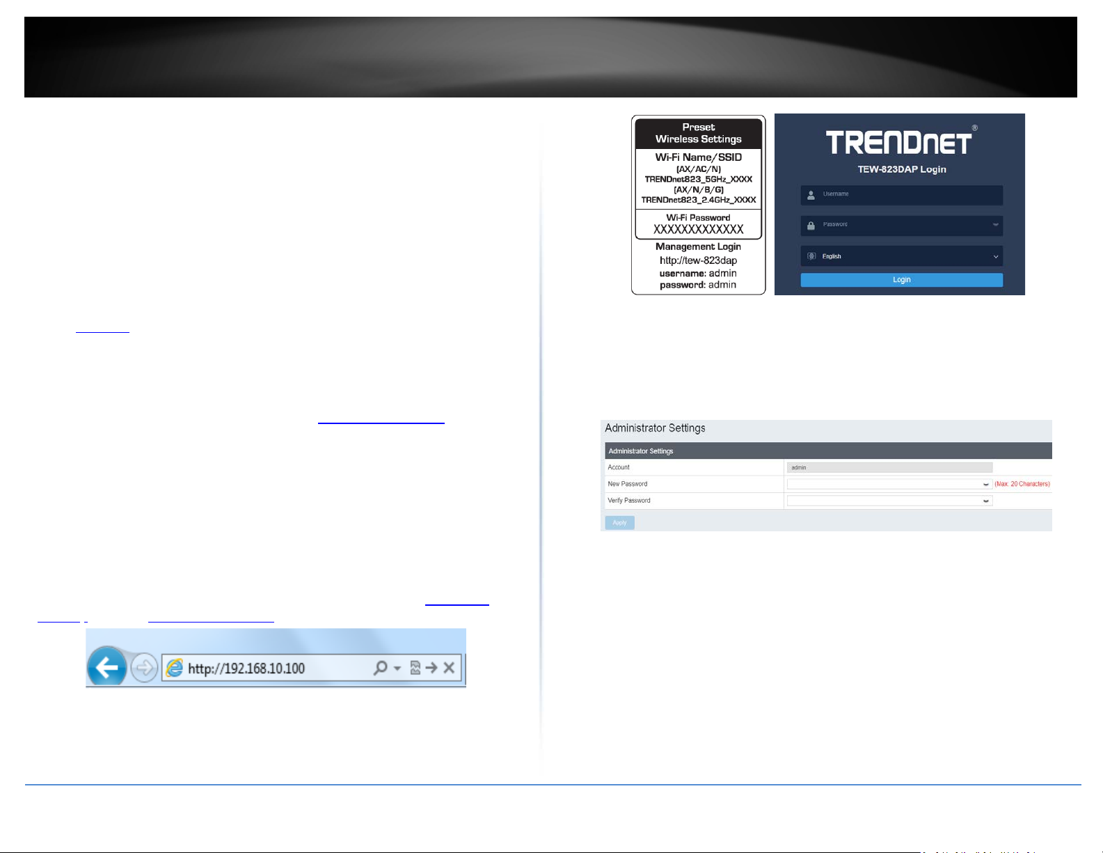
Wizard
1. For the first-time logging into the device the setup wizard will start automatically.
2. For your security, the first step is to change the login password of the access point.
Enter your new login password and click apply.
Indoor Wireless Access Points
IP Address: 192.168.10.xxx
Subnet Mask: 255.255.255.0
1. Open your web browser (e.g. Internet Explorer, Firefox, Safari, Chrome, or Opera) and
go to “http://model number” (ie: if your AP is TEW-823DAP, type in
823dap) or type in http://192.168.10.100.
2. Enter the default user name and password and then click Login. You can find your
device's SSID and WiFi password on the white labels located on the device. Use this
information to connect to the access point.
© Copyright 2023 TRENDnet. All Rights Reserved.
http://tew-
3. Your new password settings will be applied and you will be redirected to the login
screen. You will need to use the new login password to proceed.
11
Page 15
Security Standard
WPA
WPA2
WPA3
Standards
IEEE 802.11a/b/g
using this standard)
IEEE 802.11a/b/g/n
IEEE 802.11 n/ac/ax
Highest
Setting
Up to 54Mbps
1.3Gbps (11ac)*
(11ax)*
Encryption
Strength
Medium
High
Highest
TKIP
8-63 characters
AES
8-63 characters
AES
8-63 characters
*Dependent on the maximum 802.11n/ac/ax data rate supported by the device
(150Mbps, 300Mbps, 450Mbps, 867Mbps, 1.3Gbps, 2.4Gbps, or 4.8Gbps)
TRENDnet User’s Guide
Wireless Networking and Security
How to choose the type of security for your wireless network
Setting up wireless security is very important. Leaving your wireless network open and
unsecure could expose your entire network and personal files to outsiders. TRENDnet
recommends reading through this entire section and setting up wireless security on your
new access point.
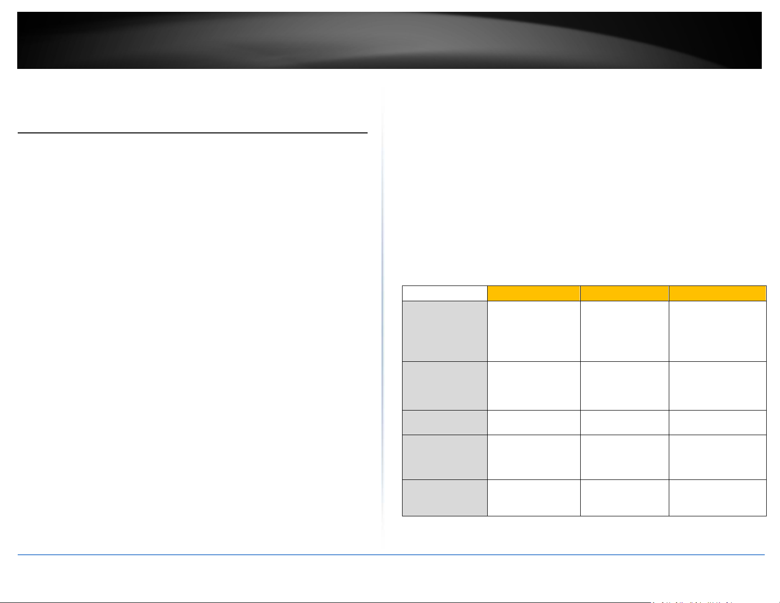
There are a few different wireless security types supported in wireless networking each
having its own characteristics which may be more suitable for your wireless network
taking into consideration compatibility, performance, as well as the security strength
along with using older wireless networking hardware (also called legacy hardware).
It is strongly recommended to enable wireless security to prevent unwanted users from
accessing your network and network resources (personal documents, media, etc.).
In general, it is recommended that you choose the security type with the highest
strength and performance supported by the wireless computers and devices in your
network. Please review the security types to determine which one you should use for
your network.
Wireless Encryption Types
• WPA/WPA2-Personal: This setting provides the router with the ability to detect
wireless devices using either WPA or WPA2 encryption. Your wireless network will
automatically change the encryption setting based on the first wireless device
connected. For example, if the first wireless client that connects to your wireless
network uses WPA encryption your wireless network will use WPA encryption. Only
when all wireless clients disconnect to the network and a wireless client with WPA2
encryption connects your wireless network will then change to WPA2 encryption.
Note: WPA2 encryption supports 802.11n speeds and WPA encryption will limit
your connection speeds to 54Mbps
• WPA2-Personal: This is the most secure wireless encryption available today, similar
to WPA encryption but more robust. This encryption standard also supports the
highest connection speeds. TRENDnet recommends setting your router to this
encryption standard. If you find that one of your wireless network devices does not
support WPA2 encryption, then set your router to either WPA or WPA-Auto
encryption.
Note: Check the specifications of your wireless network adapters and wireless
appliances to verify the highest level of encryption supported. Below is brief
comparison chart of the wireless security types and the recommended
configuration depending on which type you choose for your wireless network.
• WPA3-Personal: This is the latest wireless encryption. It is similar to WPA2
encryption, but more robust. This encryption standard also supports the highest
possible connection speed. TRENDnet recommends setting your router to this
encryption standard. If you find that one of your wireless network devices does not
support WPA3 encryption, then set your router to either WPA2 or WPA encryption.
• WPA2/WPA3-Personal: This setting provides the router with the ability to detect
wireless devices using either WPA2 or WPA3 encryption. Your wireless network will
automatically change the encryption setting based on the first wireless device
connected.
Note: Check the specifications of your wireless network adapters and wireless
appliances to verify the highest level of encryption supported. Below is brief
comparison chart of the wireless security types and the recommended
configuration depending on which type you choose for your wireless network
(802.11n devices
Compatible
Wireless
Performance
Under This
Additional
Options
Recommended
Configuration
will operate at
802.11g to connect
TKIP or AES,
Preshared Key or
RADIUS
Preshared Key
Indoor Wireless Access Points
Up to 450Mbps
(11n) and up to
TKIP or AES,
Preshared Key or
RADIUS
Preshared Key
Up to 600Mbps (11n)
and up to 4.8Gbps
AES
Preshared Key
© Copyright 2023 TRENDnet. All Rights Reserved.
12
Page 16
TRENDnet User’s Guide
Secure your wireless network
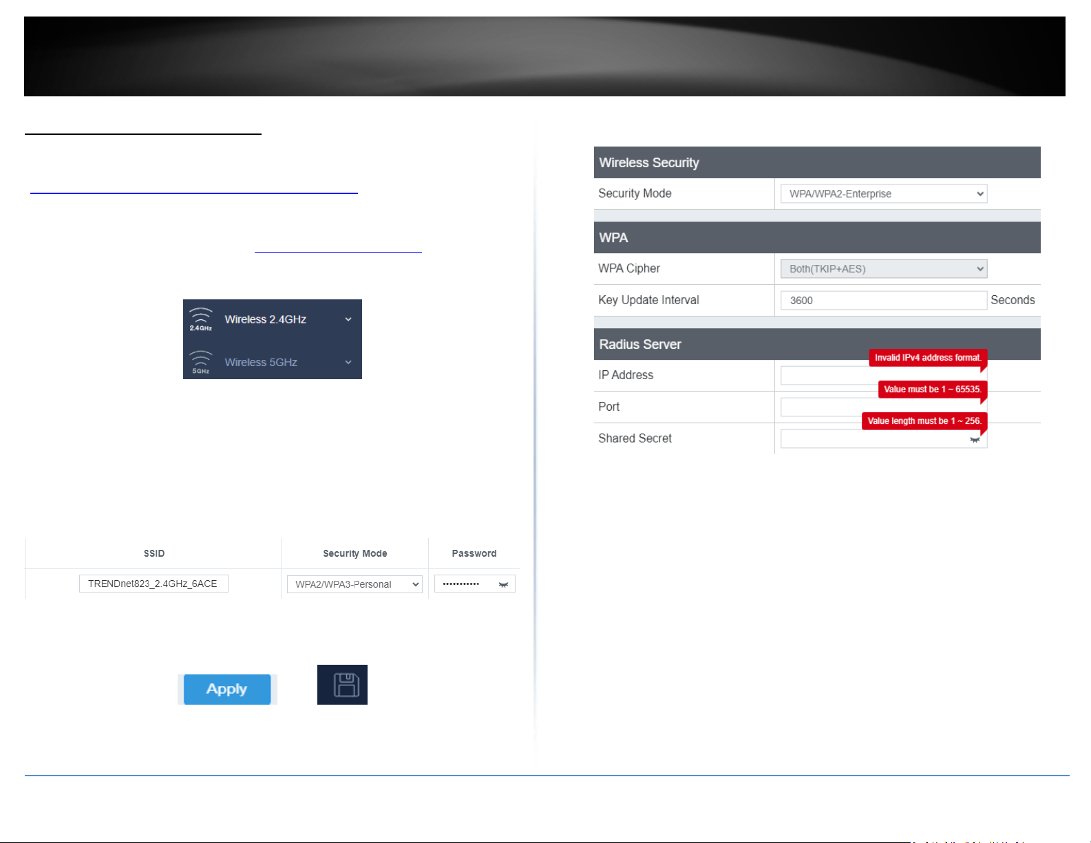
Wireless (2.4GHz or 5GHz)> Security
After you have determined which security type to use for your wireless network (see
“How to choose the security type for your wireless network
wireless security.
1. Log into your management page (see “Access the management page
2. Click on the Wireless 2.4GHz or 5GHz.
3. Underneath the wireless band section, you will see the Current Profiles of all your
wireless network listed.
4. Select the desired Security Mode from the drop down menu and enter the password
in the Password field.
Note: To select an encryption mode not included in the Security Mode drop down, click
on Edit to select another encryption mode.
5. Click Apply then click the Save button on the top-right when finished.
Selecting WPA-Enterprise, WPA2-Enterprise, or WPA2-Enterprise Mixed:
” on page 12), you can set up
” on page 13).
The following section outlines options when selecting WPA/WPA2-Enterprise, WPA2-
Enterprise or WPA3-Enterprise known as EAP (Extensible Authentication Protocol). Also
known as called Remote Authentication Dial-In User Service or RADIUS.
Note: This security type requires an external RADIUS server, PSK only requires you to
create a passphrase.
• WPA Cipher: Select a Cipher Type to use. When selecting WPA-PSK security, it is
recommended to use TKIP + AES.
• Key Update Interval: Enter the time interval (seconds) of when the network
passphrase will rotate.
Note: It is recommended to use the default interval time. Your passphrase will not
change; rotation of the key is part of the WPA protocol and designed to increase
security.
• IP Address: Enter the IP address of the RADIUS server. (e.g. 192.168.10.250)
• Port: Enter the port your RADIUS server is configured to use for RADIUS
authentication.
Note: It is recommended to use port 1812 which is typical default RADIUS port.
Indoor Wireless Access Points
© Copyright 2023 TRENDnet. All Rights Reserved.
13
Page 17

TRENDnet User’s Guide
• Shared Secret: Enter the shared secret used to authorize your router with your
RADIUS server.
Indoor Wireless Access Points
© Copyright 2023 TRENDnet. All Rights Reserved.
14
Page 18
TRENDnet User’s Guide
Connect wireless devices using WPS
WPS (Wi-Fi Protected Setup) is a feature that makes it easy to connect devices to your
wireless network. If your wireless devices support WPS, you can use this feature to
easily add wireless devices to your network.
Note: You will not be able to use WPS if you set the SSID Broadcast setting to Disabled or
if you are using WEP security.
There are two methods the WPS feature can easily connect your wireless devices to
your network.
• Push Button Configuration (PBC) method
o WPS Software/Virtual Push Button - located in the management page
• PIN (Personal Identification Number) Method - located in the management page
Note: Refer to your wireless device documentation for details on the operation of
WPS.
For connecting additional WPS supported devices, repeat this process for each
additional device.
PBC (Software/Virtual Push Button)
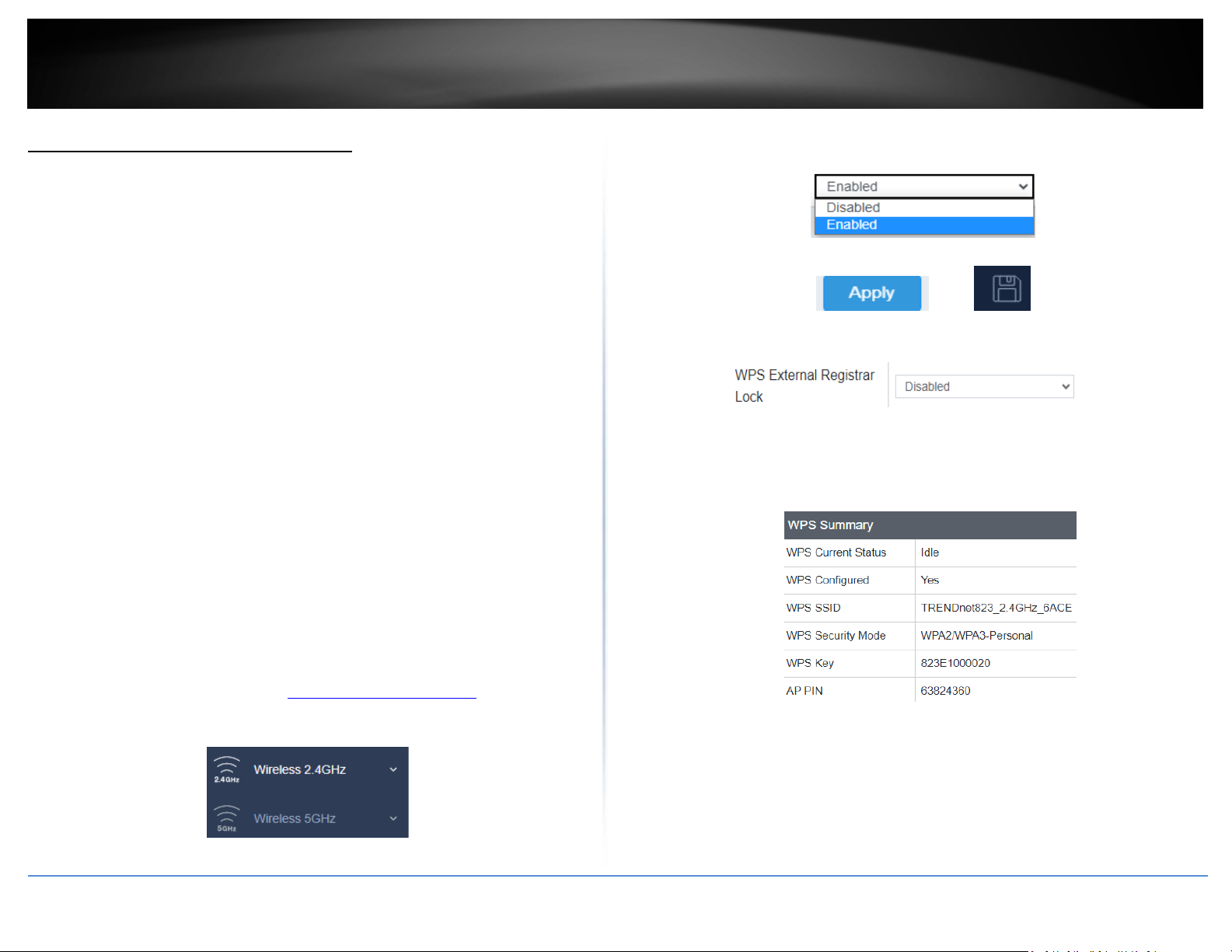
Wireless (2.4GHz or 5GHz)> WPS
In addition to the hardware push button located physically on your router, the router
management page also has push button which is a software or virtual push button you
can click to activate WPS on your router.
1. Log into your management page (see “Access the management page
2. Click on the Wireless network you want to configure button (Wireless 2.4GHz or
5GHz) and click WPS.
3. Click on WPS to configure the selected wireless band’s WPS feature. Select Enabled to
enable WPS on the selected wireless band.
4. Click Apply then click the Save button on the top-right when finished.
WPS Config
• WPS External Registrar Lock: Select to enable or disable external registrar feature
on the select wireless band.
WPS Summary
” on page 13).
• WPS Current Status: Displays the status of WPS feature on the selected wireless
band
• WPS Configure: Displays the configured mode of the WPS feature
• WPS SSID: Displays the SSID of the WPS network
• WPS Security Mode: Display the security mode of the WPS network
• WPS Key: Displays the security password
• AP PIN: Display the WPS PIN information.
Indoor Wireless Access Points
© Copyright 2023 TRENDnet. All Rights Reserved.
15
Page 19
TRENDnet User’s Guide
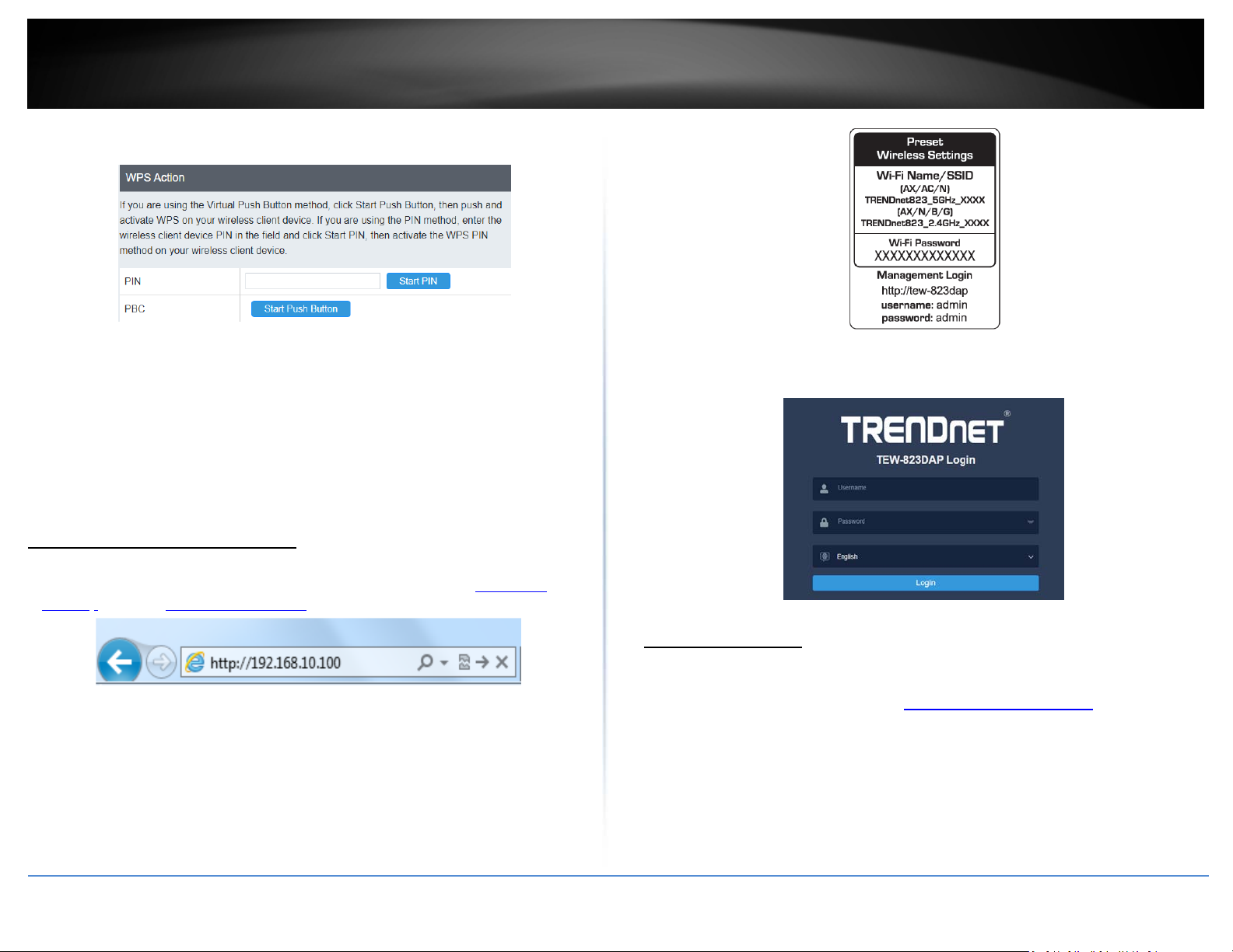
WPS Action
• PIN: Enter the PIN information of the wireless client you want to connect to the
network. Click Start PIN button to activate WPS once you enter the client’s PIN
information
Note: You may need to initiate the WPS PIN on your wireless device first when
using this method. Refer to your wireless device documentation for details on the
operation of WPS.
• PBC: Click Start Push Button to activate WPS PBC configuration.
3. Enter your Username and Password, select your preferred language, and then click
Login.
Indoor Wireless Access Points
Advanced configuration
Access the management page
1. Open your web browser (e.g. Internet Explorer, Firefox, Safari, Chrome, or Opera) and
go to “http://model number” (ie: if your AP is TEW-823DAP, type in
823dap) or type in http://192.168.10.100.
http://tew-
Operating Modes
This section outlines the available operating modes available on the access point.
2. Enter the default user name and password and then click Login. You can find your
device's SSID and WiFi password on the white labels located on the device. Use this
information to connect to the access point.
© Copyright 2023 TRENDnet. All Rights Reserved.
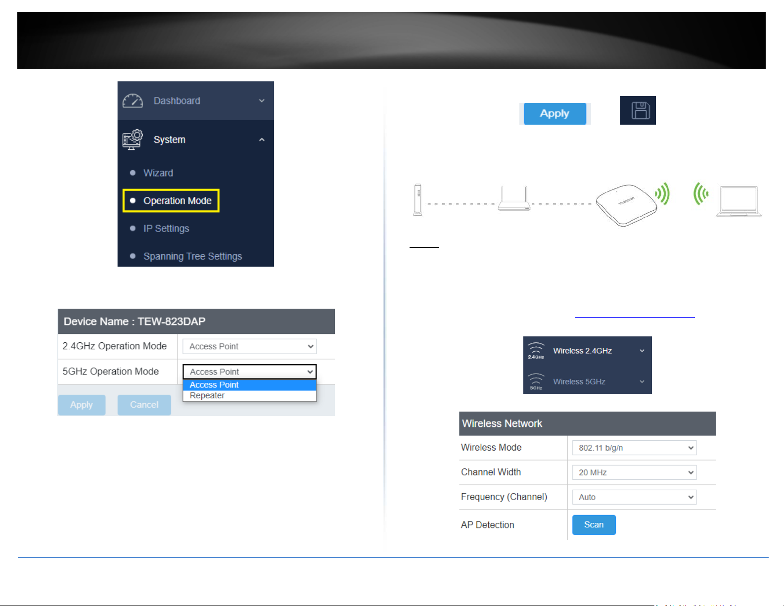
1. Log into your management page (see “Access the management page
2. Click on System and Operation Mode.
” on page 13).
16
Page 20
TRENDnet User’s Guide
4. Click Apply then click the Save button on the top-right when finished.
Indoor Wireless Access Points
Access Point
Basic
3. Select the operating mode to apply on each wireless band.
Wireless (2.4GHz or 5GHz) > Wireless Network
This section outlines the available features to configure for both wireless 2.4Ghz and
5GHz when Access Point mode is selected.
1. Log into your management page (see “Access the management page
2. Click on the wireless band you would like to configure and click Wireless Network.
” on page 13).
3. Configure the below settings and click Save to save settings.
• Access Point: In this mode, the device creates a wireless network to your existing
network.
• Repeater: In this mode, the wireless interface repeats wireless signal and packets
for backbone communication as well as a client access. This feature is used to
expand your existing wireless network to areas that your current access point is
unable to reach. Make sure all of the settings of the wireless interface matches to
your root or connecting wireless access points, same SSID, channel and wireless
encryption settings.
© Copyright 2023 TRENDnet. All Rights Reserved.
17
Page 21
TRENDnet User’s Guide
4. Click Apply then click the Save button on the top-right when finished.
• Wireless Mode: If all of the wireless devices you want to connect with this Access
Point can connect in the same transmission mode, you can improve performance
slightly by choosing the appropriate mode. If you have some devices that use a
different transmission mode, choose the appropriate mode.
2.4GHz Wireless
o AX only: This mode only allows devices to connect to the access point using the
latest 802.11ax technology. This mode ensures the highest throughput from the
access point, however, if you have older 802.11n wireless clients, they will no
longer be able to connect to this router.
Note: This wireless mode is only available with TEW-923DAP and TEW-925DAP.
o B/G/N mixed: Select this mode for the best compatibility. This mode allows older
802.11b and 802.11g wireless devices to connect to the access point in addition
to newer 802.11n devices.
o B/G mixed: This mode only allows devices to connect to the access point using
older and slow 802.11b or 802.11g technology and it thereby reduces the router’s
maximum speed to 54Mbps (typically not recommended).
o N only: This mode only allows newer 802.11n devices to connect to your access
point. If you have older 802.11g wireless clients, they will no longer be able to
connect to this router.
o G only: This mode only allows devices to connect to the access point using older
and slower 802.11g technology (typically not recommended).
o B only: This mode only allows devices to connect to the access point using older
and slower 802.11b technology (typically not recommended).
Note: Please check the specifications on your wireless devices for the highest
wireless capability supported first before applying these settings. If you are
unsure, it is recommended that you keep the default setting (B/G/N mixed) for the
best compatibility.
5GHz Wireless
o AX only: This mode only allows devices to connect to the access point using
newer and faster 802.11ax technology. Devices with 802.11ac connected on this
mode will not result in the full throughput allowed by the 802.11ax standard.
Note: This wireless mode is only available with TEW-923DAP and TEW-925DAP.
© Copyright 2023 TRENDnet. All Rights Reserved.
o A only: This mode only allows devices to connect to the access point using older
and slower 802.11a technology (typically not recommended).
o A/N mixed: This mode only allows devices to connect to the access point using
older and slower 802.11a or 802.11n technology and it thereby reduces the
access point’s maximum speed to 54Mbps (typically not recommended).
o N only: This mode only allows newer 802.11n devices to connect to your access
point. This mode does ensure the highest speed and security for your network,
however, if you have older 802.11a wireless clients, they will no longer be able to
connect to this router.
o N/AC mixed: Select this mode for the best compatibility. This mode allows older
802.11a wireless devices to connect to the access point in addition to newer
802.11ac devices.
Note: Please check the specifications on your wireless devices for the highest
wireless capability supported first before applying these settings. If you are
unsure, it is recommended that you keep the default setting (N/AC mixed) for the
best compatibility.
When applying the 802.11 mode setting, please keep in mind the following:
• Wireless devices that support 802.11n are backwards compatible and can
connect wirelessly at 802.11g or 802.11b.
• Connecting at 802.11b or 802.11g will limit the capability of your 802.11n
supported wireless devices from obtaining higher performance and data rates.
• Allowing 802.11b or 802.11g devices to connect to an 802.11n capable wireless
network may degrade the wireless network performance below the higher
performance and data rates of 802.11n.
• Wireless devices that only support 802.11b or 802.11g will not be able to
connect to a wireless network that is set to 802.11n only mode.
• Wireless devices that only support 802.11b will not be able to connect to a
wireless network that is set to 802.11g only mode.
• Channel Width: Select the channel width for the access point to operate on. By
default, the access point is on 20MHz for 2.4GHz and 80MHz for 5GHz.
• Extension channel: When 20/40 channel bandwidth has been chosen, you should
select extension channel to get higher throughput.
• Frequency (Channel): In North America, this access point can broadcast on 1 of 11
Channels for 2.4GHz (13 in Europe and other countries). On 5GHz, this access point
can broadcast on 36, 40, 44, 48, 149, 153, 157, 161 in North America. Selecting the
Auto option enables the router to automatically select the best Channel for wireless
communication. To manually set the channel on which the router will broadcast,
click the drop-down list and select the desired Channel for wireless communication.
Indoor Wireless Access Points
18
Page 22
TRENDnet User’s Guide
The goal is to select the Channel that is least used by neighboring wireless
networks.
Wireless Profile
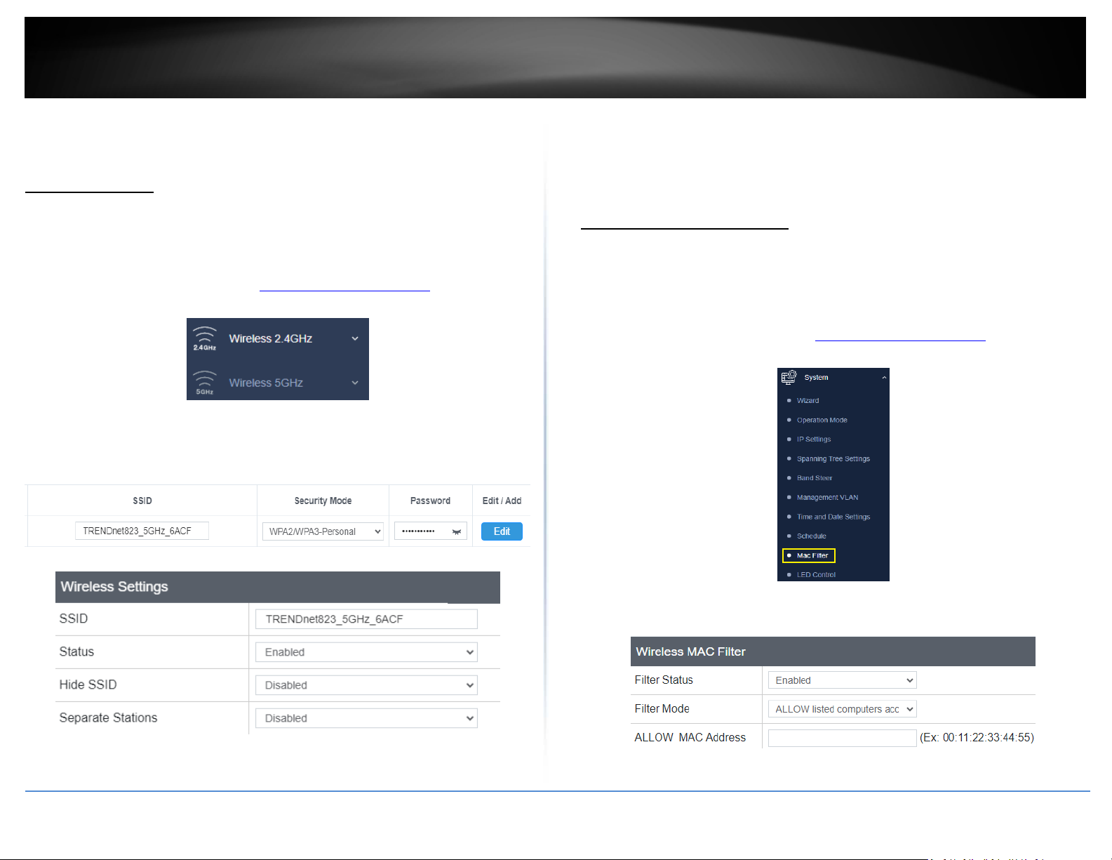
Wireless (2.4GHz or 5GHz) > Wireless Network
This section outlines the available features to configure for both wireless 2.4Ghz and
5GHz when Access Point mode is selected.
1. Log into your management page (see “Access the management page
2. Click on the wireless band you would like to configure and click Wireless Network.
3. Underneath the basic wireless band section, you will see Wireless Network and all
your wireless network profiles will be listed.
4. Click on the Edit button next to the wireless profile you want to configure.
• Status: Select Disabled to disable this wireless profile or Enabled to enable it
• Hide SSID: Select option to disable the wireless network name to broadcast
• Separate Stations: Select this option to restrict wireless client devices from
accessing other client devices connected to this network(s).
MAC filter (TEW-823DAP)
System > MAC Filter
Every network device has a unique, 12-digit MAC (Media Access Control) address. Using
” on page 13).
wireless MAC filters, you can allow or deny specific wireless clients using this access
point’s wireless network.
1. Log into your management page (see “Access the management page
2. Click on System and click MAC Filter.
Indoor Wireless Access Points
” on page 13).
5. Review the wireless settings, click Save and Apply/Discard Changes when finished.
3. Review the settings and click Apply and Save button to save settings.
• SSID: Enter the wireless network name (SSID) to assign to the selected wireless
profile
© Copyright 2023 TRENDnet. All Rights Reserved.
19
Page 23
TRENDnet User’s Guide
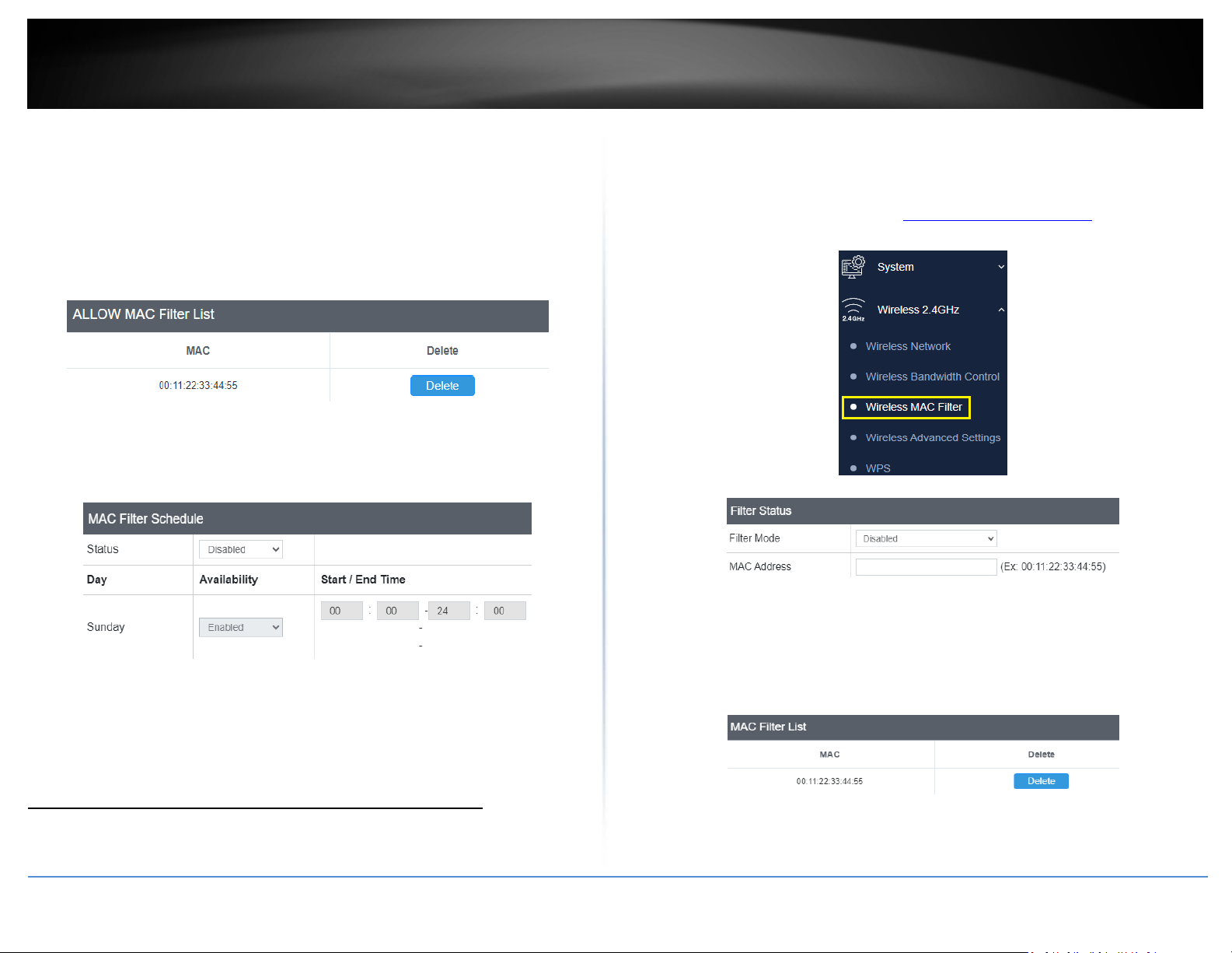
• Filter Status: Select Enable to enable Wireless MAC Filter Settings, or Disabled to
disable it.
• Filter Mode: Select from the pull-down list the MAC filter rule to apply.
o DENY: Select this option to DENY all listed MAC addressed
o ALLOW: Select this option to only ALLOW the listed MAC address to the network.
• ALLOW MAC Address: Enter the MAC address to apply on the MAC filter rule
MAC Filter List
• MAC: List of all MAC addresses
• Delete: Click to remove the selected MAC address from the MAC Filter List
MAC Filter Schedule
Every network device has a unique, 12-digit MAC (Media Access Control) address. Using
wireless MAC filters, you can allow or deny specific wireless clients using this access
point’s wireless network.
1. Log into your management page (see “Access the management page
2. Click on System and click MAC Filter.
3. Review the settings and click Apply and Save button to save settings.
Indoor Wireless Access Points
” on page 13).
• Filter Mode: Select from the pull-down list the MAC filter rule to apply.
o DENY: Select this option to DENY all listed MAC addressed
o ALLOW: Select this option to only ALLOW the listed MAC address to the network.
• Status: Select Enabled to enable MAC Filter Schedule, or Disabled to disable it
• Availability: Select Enabled for the AP to allow access for all the MAC
addresses on the MAC Filter List based off of the day
• Start/End Time: Input the time when the selected MAC addresses will be
allowed to have access
Wireless MAC Filter (TEW-923DAP / TEW-925DAP)
Wireless (2.4GHz or 5GHz) > Wireless MAC Filter
© Copyright 2023 TRENDnet. All Rights Reserved.
• ALLOW MAC Address: Enter the MAC address to apply on the MAC filter rule
MAC Filter List
• MAC: List of all MAC addresses
• Delete: Click to remove the selected MAC address from the MAC Filter List
20
Page 24
TRENDnet User’s Guide
Band Steering
System > Band Steering
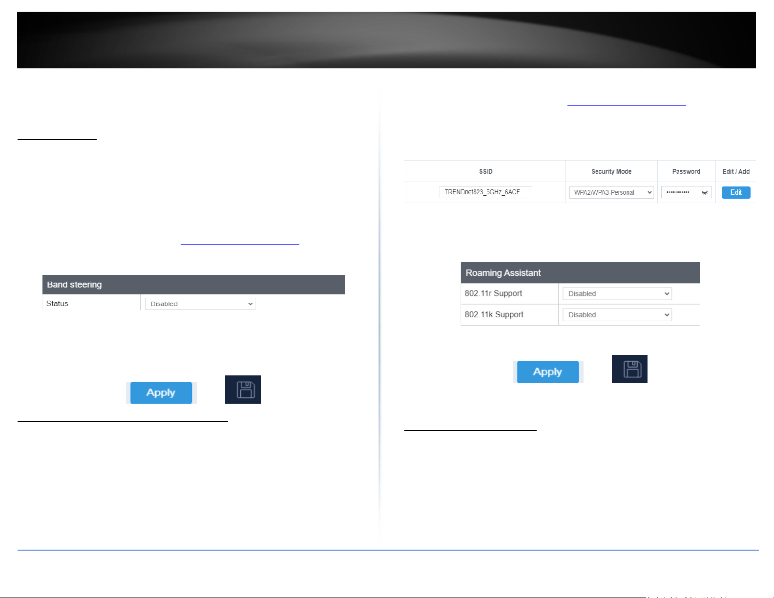
When both 2.4GHz and 5GHz bands are using the same SSID and WiFi security settings,
this feature allows the AP to automatically detect if clients are 11AC capable and
automatically pushing them over to the underutilized 5GHz bands. This allows your AP
to use both bands more efficiently and making sure clients capable of the 11AC standard
for faster speeds are establish WiFi links at 11AC connectivity whenever possible.
1. Log into your management page (see “Access the management page
2. Click on the System tab and click Band Steer.
3. Select enable to turn on band steering feature and click Apply to save settings.
4. Click Apply button to save the settings and then click on the Save button located on
the top left section to save the settings.
To enable band steering, you have to setup steering SSID the same in both 2.4GHz and
5GHz
” on page 13).
1. Log into your management page (see “Access the management page
2. Click on Wireless (2.4GHz or 5GHz), and click Wireless Network.
3. Under the Current Profiles section, click Edit for the profile you would like to
configure.
4. Under the Roaming Assistant section, select Enabled for 802.11k and 802.11r
support option to enable 802.11k and 802.11r support. The Scan Period defines how
often the access point will scan for information about other access points on the
wireless network.
5. Click Apply then click the Save button on the top-right when finished.
Indoor Wireless Access Points
” on page 13).
Roaming Support (802.11k / 802.11r)
Wireless (2.4GHz or 5GHz) > Wireless Network
The 802.11k standard is an enhancement to wireless roaming technology. It allows
wireless access points to exchange and learn information about other access points on
the network such as signal strength and client utilization and provide this information to
802.11k capable wireless client devices. Wireless client devices can use the information
about other wireless network and make more intelligent decisions when roaming from
one wireless access point to another. This also assists in better access point client
utilization. Note: This function can only work with 802.11k capable wireless client
devices. Please check your device specifications with your manufacturer for details.
© Copyright 2023 TRENDnet. All Rights Reserved.
Change your IP address
System > IP Settings
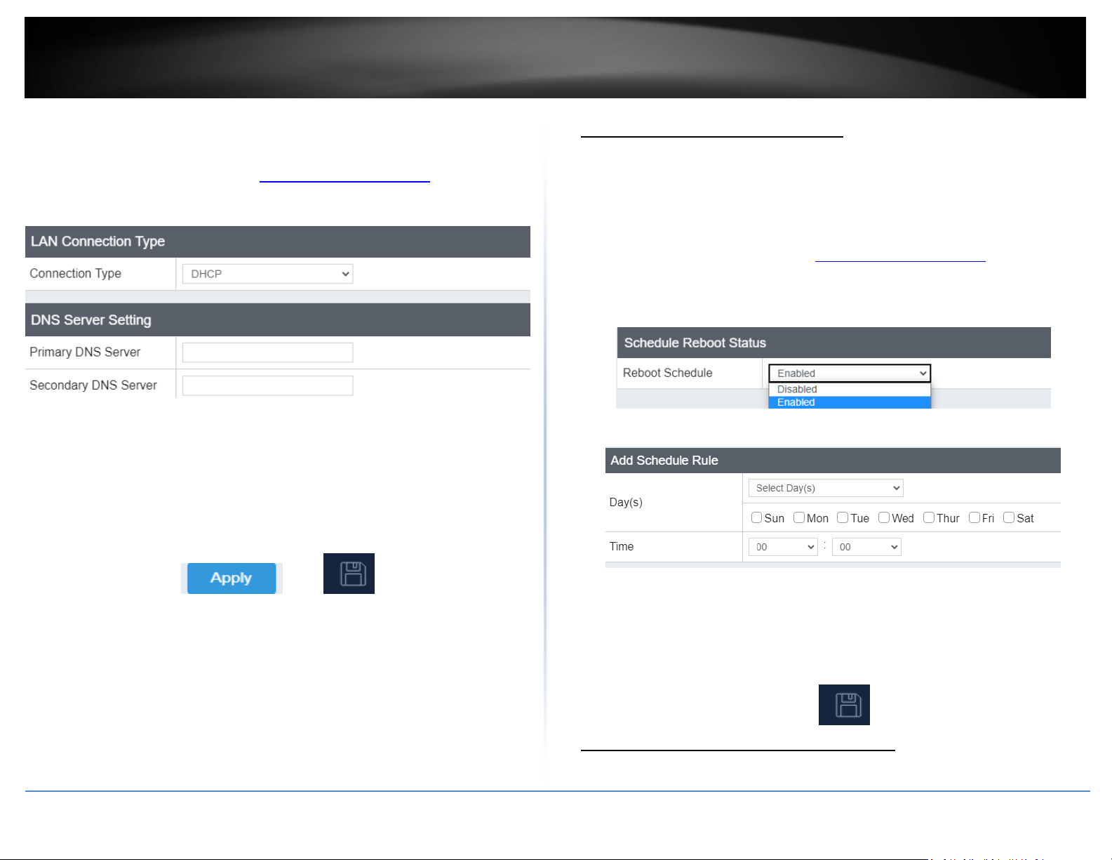
In most cases, you do not need to change the IP address settings. Typically, the IP
address settings only needs to be changed, if you plan to use another access point in
your network with the same IP address settings, if you are connecting your access point
to an existing network that is already using the IP address settings your access point is
using.
Note: If you are not encountering any issues or are not faced with one of the cases
described above or similar, it is recommended to keep your router IP address settings as
default.
21
Page 25
TRENDnet User’s Guide
Default Access Point IP Address: 192.168.10.100 / 255.255.255.0
1. Log into your management page (see “Access the management page
2. Click on the System tab and click IP Settings.
3. Review the settings and click Save to save changes.
• Connection Type: Select on the pull-down menu the LAN connection type.
o DHCP: Select this option to have the access point obtain an IP address from your
DHCP server
o STATIC: Select this option to manually assign and IP address to your access point
• DNS Server: Enter your network’s DNS server IP address
4. Click Apply then click the Save button on the top-right when finished.
Reboot Schedule (TEW-823DAP)
System > Schedule
” on page 13).
Create a schedule to define the days/time period when the access point will be
rebooted. Rebooting the access point could help clear the cache and improve
performance.
1. Log into your management page (see “Access the management page
2. Click on the System tab and click Schedule.
3. Select from the pull-down menu under Reboot Schedule to enable wireless
schedules.
4. Review the settings and click Apply to save settings.
• Day: Check the day(s) to implement the schedule.
• Time: Select the time from the drop down menu.
4. After clicking Add, click on the Save button located on the top right section to save
the settings.
Indoor Wireless Access Points
” on page 13).
Schedule (TEW-923DAP/TEW-925DAP)
System > Schedule
© Copyright 2023 TRENDnet. All Rights Reserved.
22
Page 26
TRENDnet User’s Guide
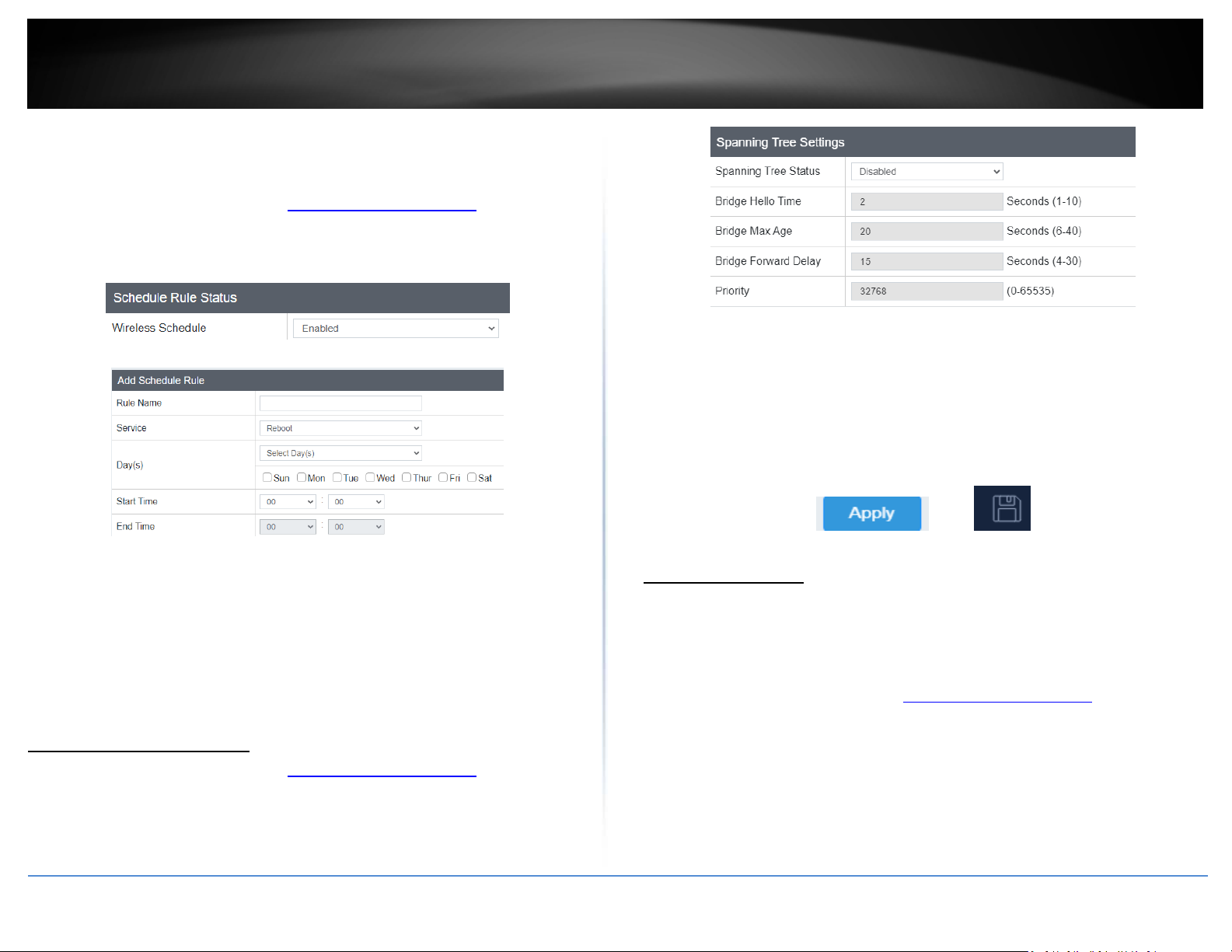
Create a schedule to define the days/time period when the access points will be
rebooted, or when the wireless networks will be activated.
1. Log into your management page (see “Access the management page
2. Click on the System tab and click Schedule.
3. Select from the pull-down menu under Wireless Schedule to enable wireless
schedules.
4. Review the settings and click Add to save the settings.
• Rule Name: Input the name for the current schedule
• Service: Select the type of rule for this schedule
o Reboot: Automatically reboots the access point at the scheduled time
o 2.4GHz/5GHz/Dual Wireless: Select the selected wireless band on
when it will be enabled within your scheduled time
• Days: Select the days of when this schedule will be activated
• Start / End Time: Input the start and end time for this rule
Configure Spanning Tree
1. Log into your management page (see “Access the management page” on page 13).
2. Click on the System tab and click Spanning Tree Settings.
3. Review the settings and click Save to save changes.
” on page 13).
• Spanning Tree Status: Select Enabled or Disabled to enable or disable spanning
tree feature.
• Bridge Hello Time: Enter the bridge duration
• Bridge Max Age: Enter the max duration
• Bridge Forward Delay: Enter the delay duration
• Priority: Enter the priority
4. Click Apply then click the Save button on the top-right when finished.
Set date and time
System > Time and Date Settings
There are two ways to set the access point’s date and time. NTP (Network Time Protocol)
is based on time servers. You can also manually set the router’s date and time.
Note: It is important that the time is configured correctly before setting any schedules.
1. Log into your management page (see “Access the management page
2. Click on the System tab and click Time and Date Settings.
3. Next to Time Zone, click the drop-down list to select your time zone.
Indoor Wireless Access Points
” on page 13).
© Copyright 2023 TRENDnet. All Rights Reserved.
23
Page 27
TRENDnet User’s Guide
Indoor Wireless Access Points
Manual
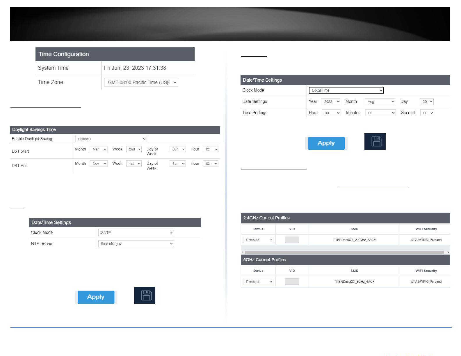
1. Manually set the date and time of the access point by selecting Local Time from the
pull-down menu.
Daylight Saving Time
When using NTP or manual configuration, you may also configure Daylight Saving
feature.
• Enable: Select Enabled to enable daylight savings or Disabled to disable it
• DST Start / DST END: Configure the start and end time of daylight savings
NTP
1. Review the settings below and click Apply to save settings.
2. Click Apply then click the Save button on the top-right when finished.
Management VLAN
System > Management VLAN
1. Log into your management page (see “Access the management page
2. Click on the Management tab and click Management VLAN.
3. Review the settings for both 2.4G and 5G profiles and click Save to save settings.
” on page 13).
• Clock Mode: Select SNTP
• NTP Server: Select the NTP server to use
2. Click Apply then click the Save button on the top-right when finished.
© Copyright 2023 TRENDnet. All Rights Reserved.
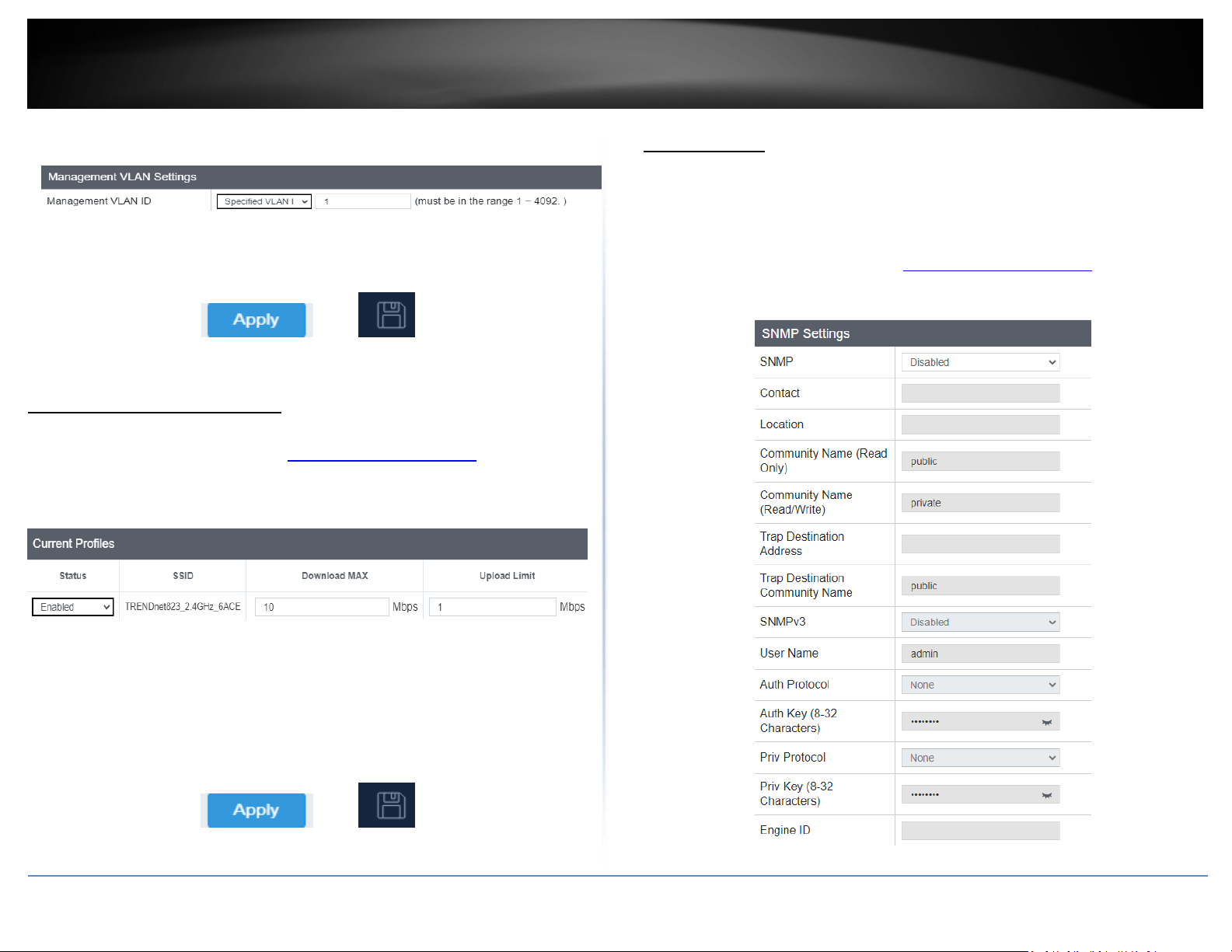
• Status: Select Enabled from the drop down menu to enable VLAN feature
• VID: Enter the VID to assign on the selected wireless network
• SSID: Displays the available SSID
24
Page 28
TRENDnet User’s Guide
• WiFi Security: Displays the wireless security type of the wireless network
• No VLAN Tag: Select this option to use no VLAN Tag
• Specified VLAN ID: Select this option and enter the assigned VLAN ID.
4. Click Apply then click the Save button on the top-right when finished.
Enable SNMP
Management > SNMP Settings
SNMP (Simple Network Management Protocol) is a network management protocol used
to monitor (read) and/or manage (write) multiple network devices on a network. This
preconfigured external SNMP server.
1. Log into your management page (see “Access the management page
2. Click on the Management tab and click SNMP Settings.
3. Review the settings and click Save to save settings.
Indoor Wireless Access Points
Wireless Bandwidth Control
Wireless (2.4GHz or 5GHz) > Wireless Bandwidth Control
1. Log into your management page (see “Access the management page
2. Click on the Wireless (2.4GHz or 5GHz) tab and click Wireless Bandwidth Control.
3. Review the settings for both wireless bands (2.4GHz and 5GHz) and click Save to save
settings.
” on page 13).
” on page 13).
• Status: Select Enable to enable bandwidth control on this SSID
• SSID: The SSID that the following limits will apply to
• Download MAX: Enter your network’s inbound traffic limit for the selected wireless
SSID
• Upload Limit: Enter your network’s outbound traffic limit for the selected wireless
SSID
4. Click Apply then click the Save button on the top-right when finished.
© Copyright 2023 TRENDnet. All Rights Reserved.
25
Page 29
TRENDnet User’s Guide
• SNMP: Select enable to enable SNMP feature
• Contact: Enter the contact person or contact information for your access point.
• Location: Enter an assigned location for your access point.
• Community Name (Read only): Enter an assigned name for your access point.
• Community (Read/Write): Enter a public and private community name.
• Trap Destination Address: Enter the destination IP address of the SNMP trap.
• Trap Destination Community Name: Enter the name of the destination community
• SNMPv3: Select option to enable or disable SNMPv3
• Username: Enter the username
• Auth Protocol: Select from the pull down menu the authentication protocol to use
• Auth Key: Enter the authentication key
• Priv Protocol: Select the private protocol
• Priv Key: Enter the private key
• Engine ID: Enter the engine name
4. Click Apply then click the Save button on the top-right when finished.
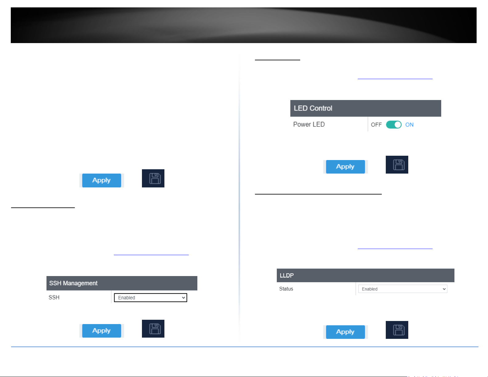
SSH Management
Management > SSH Management
SSH (Secure SHell) is a form of a CLI (Command Line Interface), a user interface where
commands can be sent to the access point in the form of successive lines of text
(command lines).
1. Log into your management page (see “Access the management page
2. Click on the Management tab and click SSH Management.
3. Select Enabled and click Apply to save settings.
LED Controls
System > LED Control
1. Log into your management page (see “Access the management page
2. Click on the System tab and click LED Control.
3. Review the settings and click Save to save settings.
• Power LED: Select On to leave Power LED on or Off option to turn off.
4. Click Apply then click the Save button on the top-right when finished.
LLDP (TEW-923DAP / TEW-925DAP)
System > LLDP
LLDP (Link Layer Discovery Protocol) is a standard method to allow networked devices to
advertise capabilities, identity and other information onto your LAN.
1. Log into your management page (see “Access the management page
” on page 16).
2. Click on the System tab and click LLDP.
3. Select Enabled to enable LLDP.
Indoor Wireless Access Points
” on page 13).
” on page 13).
4. Click Apply then click the Save button on the top-right when finished.
© Copyright 2023 TRENDnet. All Rights Reserved.
4. Click Apply then click the Save button on the top-right when finished.
26
Page 30
TRENDnet User’s Guide
Indoor Wireless Access Points
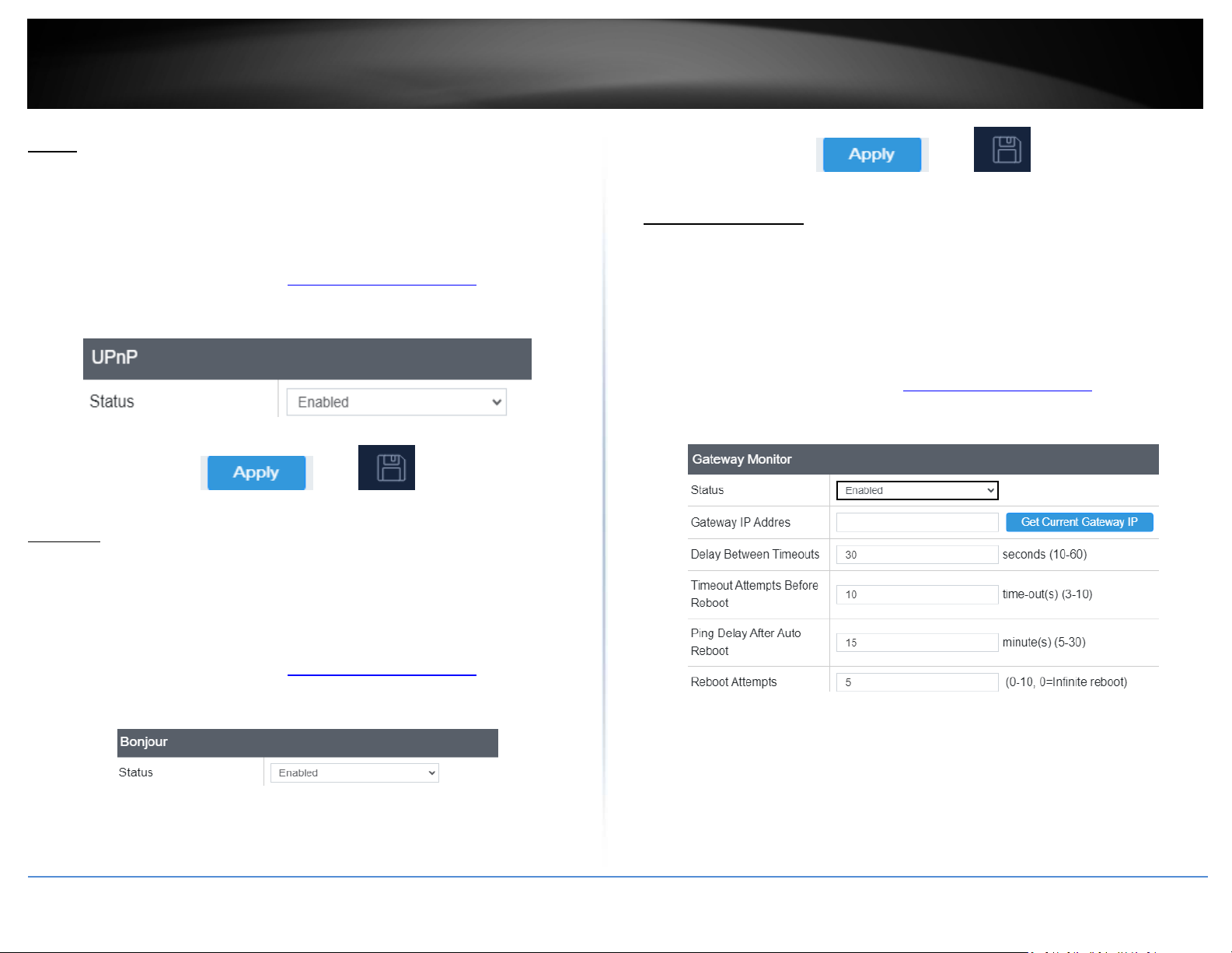
UPnP
System > UPnP
UPnP (Universal Plug and Play) enables devices to discover each other and connect
without the need for manual configuration.
1. Log into your management page (see “Access the management page
2. Click on the System tab and click UPnP.
3. Select Enabled to enable UPnP.
4. Click Apply then click the Save button on the top-right when finished.
” on page 16).
Gateway Monitor
System > Gateway Monitor
Gateway monitor is a feature that will periodically send a ping to your router. If a ping is
not received, the Access Point will automatically try to restore the connection by
rebooting the Access Point.
1. Log into your management page (see “Access the management page
2. Click on the System tab and click Bonjour.
3. Review the settings and click Apply.
” on page 16).
Bonjour
System > Bonjour
Bonjour is a zero-configuration networking networking protocol that enables automatic
discovery of devices and services on your local network.
1. Log into your management page (see “Access the management page
2. Click on the System tab and click Bonjour.
3. Select Enabled to enable UPnP.
4. Click Apply then click the Save button on the top-right when finished.
© Copyright 2023 TRENDnet. All Rights Reserved.
” on page 16).
• Status: Select Enabled to enable this feature
• Gateway IP Address: Input the IP address for your gateway, or click Get
Current Gateway IP to have your access point automatically find the gateway
on your network.
• Delay Between Timeouts: Set the time between each ping
27
Page 31
TRENDnet User’s Guide
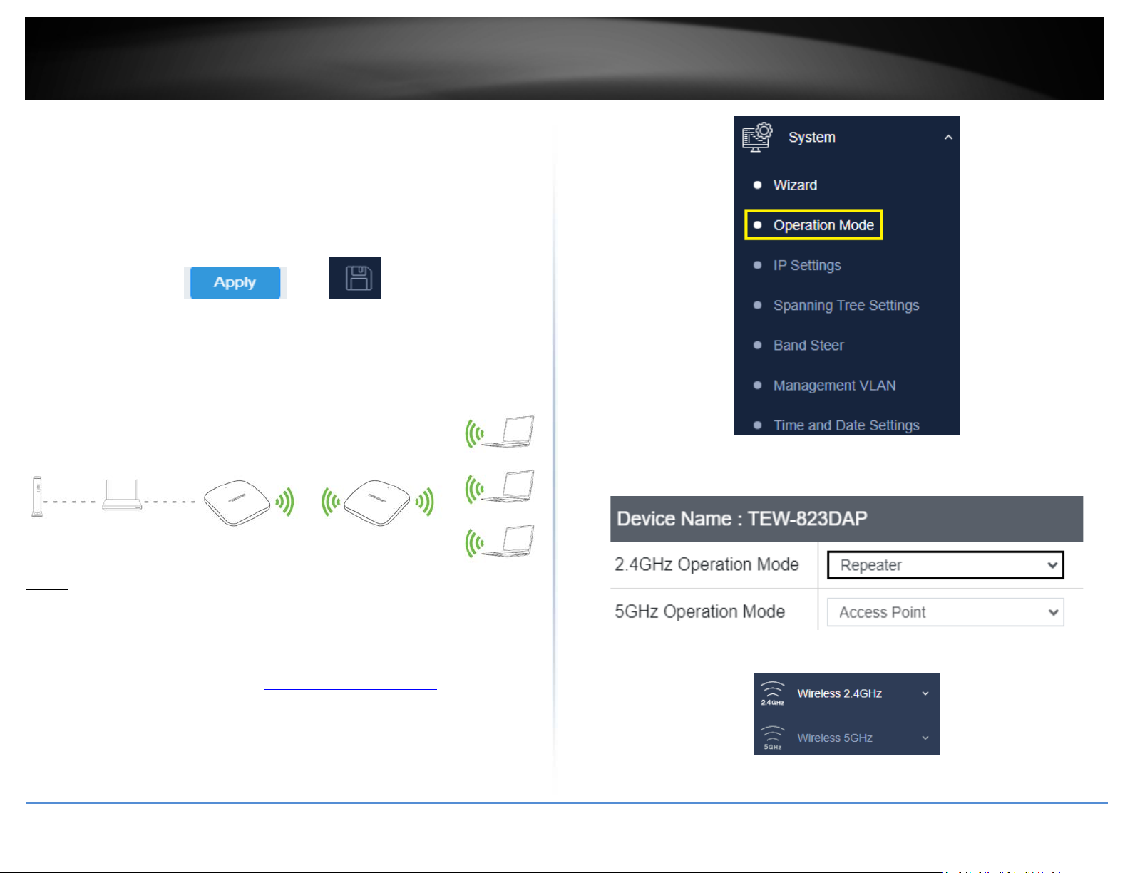
• Timeout Attempts Before Reboot: Set the number of failed pings before a
reboot occurs
• Ping Delay After Auto Reboot: Set the time before the next ping after each
reboot
• Reboot Attempts: Set the maximum number of reboots
4. Click Apply then click the Save button on the top-right when finished.
Indoor Wireless Access Points
Repeater
3. Select Repeater, under the wireless band (2.4GHz or 5GHz) you would like to connect
this access point to, then press Apply. Please make sure that the selected band is
available on your network.
Basic
Wireless (2.4GHz or 5GHz) > Wireless Network
This section outlines the available features to configure for both wireless 2.4GHz and
5GHz when Repeater mode is selected.
1. Log into your management page (see “Access the management page
2. Click on System, and select Operation Mode.
© Copyright 2023 TRENDnet. All Rights Reserved.
” on page 13).
4. Click on the wireless band (Wireless 2.4GHz / Wireless 5GHz) you would like to
configure and click Wireless Network.
28
Page 32
TRENDnet User’s Guide
5. Configure the below settings and click Save to save settings.
Indoor Wireless Access Points
Scan for wireless networks
Wireless (2.4GHz or 5GHz) > Wireless Network
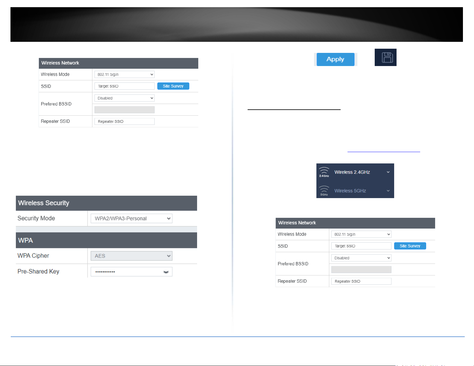
• Wireless Mode: Select the wireless mode to set on the selected wireless band in
client bridge mode
• SSID: Manually enter the wireless network name (SSID) you want to establish
connection. Or simply click on Site Survey to scan for available wireless network
(more on this function in below section).
• Preferred BSSID: Click option and enter the MAC address of the preferred wireless
network you would like to connect to.
• Repeater SSID: You may specify a new SSID name to use
This section outlines the available features to configure for both wireless 2.4Ghz and
5GHz when Repeater mode is selected.
1. Log into your management page (see “Access the management page
2. Click on the wireless band you would like to configure and click Wireless Network.
3. Under SSID section click Site Survey to wireless scan for available wireless networks.
” on page 16).
• Security Mode: Select from the pull-down menu the wireless security that is used
on the wireless network you would like to connect to.
• WPA Cipher: Select the type of encryption for the selected Security Mode
• Pre-Shared Key: Enter the password for the selected SSID
6. Click Apply then click the Save button on the top-right when finished.
© Copyright 2023 TRENDnet. All Rights Reserved.
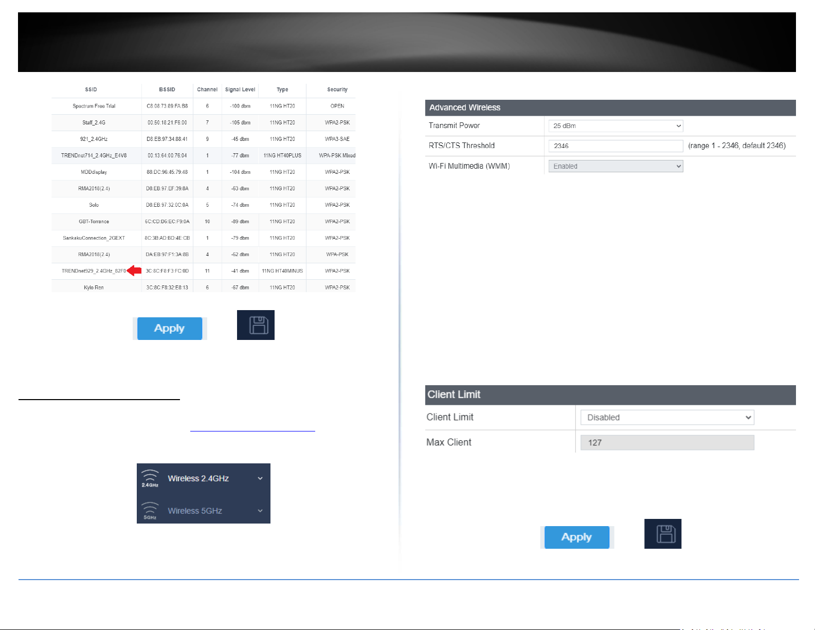
4. Click on the wireless network you would like to repeat. The information will
automatically fill on the previous screen. You will then need to select and enter the
wireless security.
29
Page 33
TRENDnet User’s Guide
5. Click Apply then click the Save button on the top-right when finished.
Advanced Wireless
• Transmit Power: The wireless transmit power can be modified to lower the
antenna strength setting from 25 dBm to 5 dBm, if necessary. Lowering the wireless
transmit power may help to better stabilize the wireless connectivity and reduce
the effects of wireless interference in areas where there are several 2.4GHz wireless
devices. (Default: 25 dBm)
• RTS/CTS Threshold: The Request To Send (RTS) function is part of the networking
protocol. A wireless device that needs to send data will send a RTS before sending
the data in question. The destination wireless device will send a response called
Clear to Send (CTS). The RTS Threshold defines the smallest data packet size
allowed to initiate the RTS/CTS function.
Default Value: 2346 (range: 256-2346)
• WMM: Select Disabled to disable WMM (Wi-Fi Multimedia)
Client Limit
Indoor Wireless Access Points
Advanced wireless settings
Wireless (2.4GHz or 5GHz) > Advanced Wireless
1. Log into your management page (see “Access the management page
2. Click on the wireless band you would like to configure and click Wireless Advanced
Settings.
3. Review the settings and click Save to save settings.
” on page 13).
• Client Limit: Select enable to turn on client limit of the select wireless band
• Max Client: Enter the amount of clients to allow
4. Click Apply then click the Save button on the top-right when finished.
© Copyright 2023 TRENDnet. All Rights Reserved.
30
Page 34
TRENDnet User’s Guide
Maintenance & Monitoring
1. Log into your management page (see “Access the management page
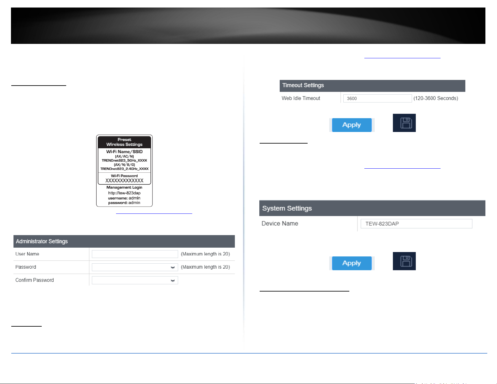
2. Click on the Management tab and click Timeout.
3. Set the duration of Idle before a timeout.
Indoor Wireless Access Points
Administration
Management > Administration
You may want to change your login credentials for logging into your access point.
Resetting the access point to factory default settings will also reset the login credentials
back to factor default which can be found on the label or on the back of the unit.
4. Click Apply then click the Save button on the top-right when finished.
Device Name
Management > System Management
1. Log into your management page (see “Access the management page
2. Click on the Management tab and click System Management.
3. In the Device Name field, change the name of the device (eg: room, office etc)
1. Log into your management page (see “Access the management page
2. Click on the Management tab and click Administration.
3. Review the settings and click Add to save settings.
” on page 13).
4. Click Apply then click the Save button on the top-right when finished.
” on page 13).
” on page 13).
• User Name: Change the login user name in this field
• Password: Change the login password in this field
• Confirm Password: Re-type the password in this field
Timeout
Management > Timeout
© Copyright 2023 TRENDnet. All Rights Reserved.
Reset to factory defaults
Management > Backup/Restore Settings
You may want to reset the access point to factory defaults if you are encountering
difficulties and have attempted all other troubleshooting. Before you reset to defaults, if
possible, you should backup your access point’s configuration first.
There are two methods that can be used to reset your access point to factory defaults.
31
Page 35
TRENDnet User’s Guide
• Reset Button: Located on the bottom of the access point, (see “Product Hardware
Features” on page 5). Use this method if you are encountering difficulties with
accessing your router management page.
OR
• Access Point Management Page
1. Log into your management page (see “Access the management page
2. Click on the Management tab and click Backup/Restore Settings.
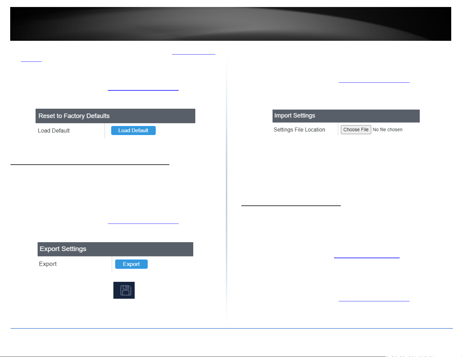
3. Click Load Default. If prompted, click Yes or Ok.
Backup and restore your configuration settings
Management > Backup/Restore Settings
You may have added many customized settings to your router and in the case that you
need to reset your router to default, all your customized settings would be lost and
would require you to manually reconfigure all of your access point settings instead of
simply restoring from a backed up router configuration file.
To back up your configuration:
1. Log into your management page (see “Access the management page
2. Click on the Management tab and click Backup/Restore Settings.
3. Click Export.
4. Click the Save button on the top-right when finished.
5. Depending on your web browser settings, you may be prompted to save a file (specify
the location) or the file may be downloaded automatically to the web browser
settings default download folder. (Default Filename: TEW-823DAP_backup.tar.gz
(1).des3)
6. Save the configuration file to location on your computer.
To restore your configuration:
1. Log into your management page (see “Access the management page
” on page 13).
2. Click on the Management tab and click Backup/Restore Settings.
3. Under Import Settings, depending on your web browser, click on Browse or Choose
File. A separate file navigation window should open.
4. Navigate to the location of the access point configuration file to restore.
(Default Filename: TEW-823DAP_backup.tar.gz (1).des3).
5. Select the access point configuration file to restore. Enter the login password under
Encrypt Key and click Save.
(Default Filename: config.bin). If prompted, click Yes or OK.
6. Wait for the access point to restore settings.
Restart (Reboot)
Management > Backup/Restore Settings
” on page 13).
You may want to restart your access point if you are encountering difficulties with your
access point and have attempted all other troubleshooting.
There are two methods that can be used to restart your access point.
• Turn the router off disconnect the power source or press the power button from
the side of your access point (see “Product Hardware Features
• Use this method if you are encountering difficulties with accessing your router
management page. This is also known as a hard reboot or power cycle.
OR
• Router Management Page: This is also known as a soft reboot or restart.
1. Log into your management page (see “Access the management page
2. Click on the Management tab and click Backup/Restore Settings.
access point
Indoor Wireless Access Points
” on page 5).
” on page 13).
” on page 13).
© Copyright 2023 TRENDnet. All Rights Reserved.
32
Page 36
TRENDnet User’s Guide
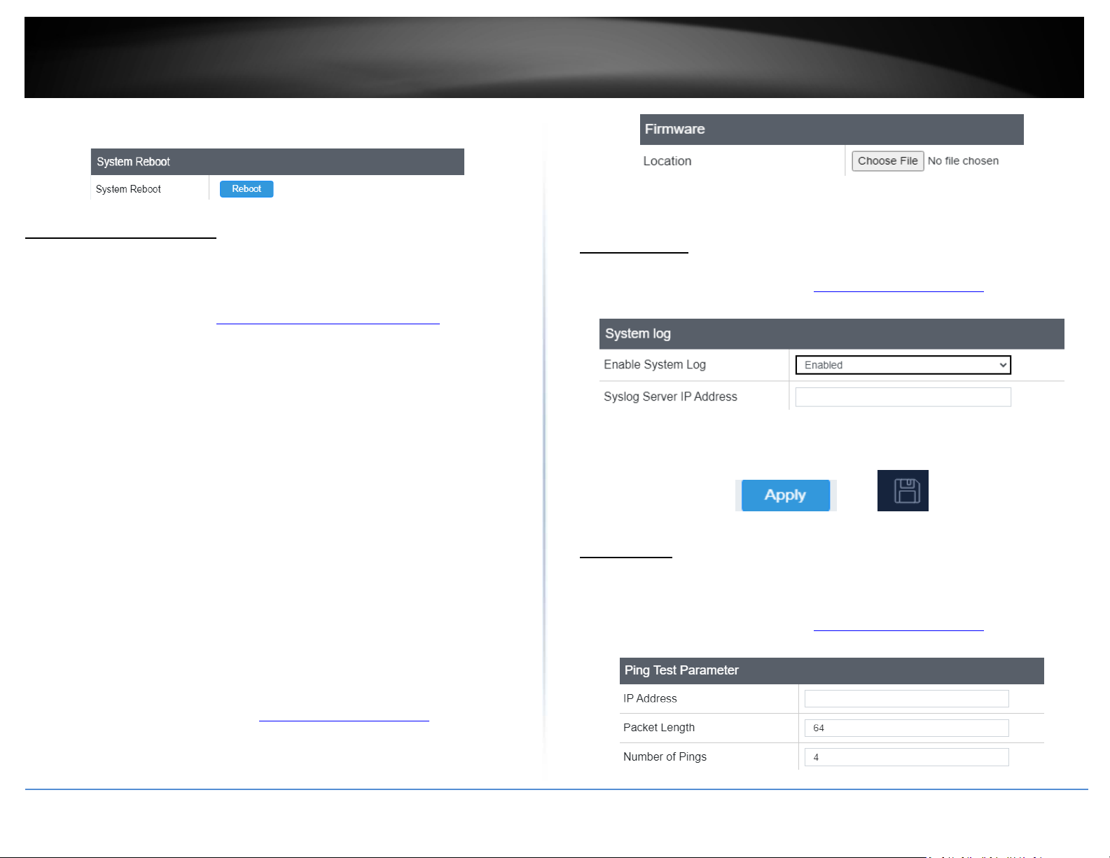
3. Click Reboot under System Reboot to restart the access point. If prompted, click yes
or OK.
4. Navigate to the folder on your computer where the unzipped firmware file (.des3) is
located and select it.
5. Click Apply to start the firmware upgrade process. If prompted, click yes or OK.
Indoor Wireless Access Points
Upgrade your firmware
Management > Upload Firmware
TRENDnet may periodically release firmware upgrades that may add features or fix
problems associated with your TRENDnet access point model and version. To check if
there is a firmware upgrade available for your device, please check your TRENDnet
model and version using the link. http://www.trendnet.com/downloads/
In addition, it is also important to verify if the latest firmware version is newer than the
one your access point is currently running. To identify the firmware that is currently
loaded on your access point, log in to the router, click on the Status tab and select Main.
If there is a newer version available, also review the release notes to check if there were
any new features you may want or if any problems were fixed that you may have been
experiencing.
1. If a firmware upgrade is available, download the firmware to your computer.
2. Unzip the file to a folder on your computer.
Please note the following:
• Do not interrupt the firmware upgrade process. Do not turn off the device or press
the Reset button during the upgrade.
• If you are upgrade the firmware using a laptop computer, ensure that the laptop is
connected to a power source or ensure that the battery is fully charged.
• Disable sleep mode on your computer as this may interrupt the firmware upgrade
process.
• Do not upgrade the firmware using a wireless connection, only using a wired
network connection.
• Any interruptions during the firmware upgrade process may permanently damage
your router.
1. Log into your management page (see “Access the management page
2. Click on Management, and click on Upload Firmware.
3. Depending on your web browser, next to Upgrade Firmware, click Browse or Choose
File.
© Copyright 2023 TRENDnet. All Rights Reserved.
” on page 13).
Configure log
Management > Log
1. Log into your management page (see “Access the management page
2. Click on the Management tab and click Log. Click apply to save settings
• Enable System log: Select option to enable system log feature
• Syslog Server IP Address: Enter the IP address of the syslog server
3. Click Apply then click the Save button on the top-right when finished.
” on page 13).
Diagnostics
Management > Diagnostics
Ping Test
1. Log into your management page (see “Access the management page
2. Click on the Management tab and click Diagnostics.
” on page 13).
33
Page 37
TRENDnet User’s Guide
• IP Address: Enter the IP address you would like to conduct the ping test
• Packet Length: Enter the packet size
• Number of Pings: Enter the amount of pings to conduct.
• Ping: Click to start ping test
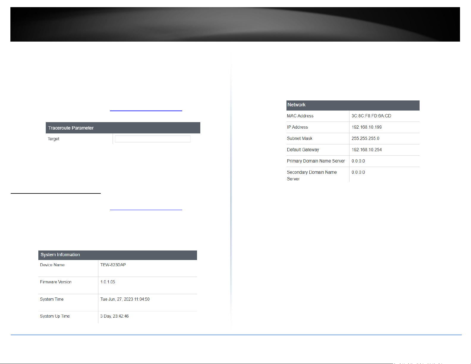
TraceRoute
1. Log into your management page (see “Access the management page
2. Click on the Management tab and click Diagnostic.
• Target: Enter the IP address to conduct traceroute test
• Traceroute: Click to start traceroute test
Check system information
Dashboard > Dashboard
1. Log into your management page (see “Access the management page
2. Click on the Status tab and click Main.
3. Review the device information.
System
• Device Name: Displays the assigned device name
• Firmware Version: Displays the firmware version currently loaded on the router
• System Time: Displays the current time of the device
• System Up Time: Displays the time duration of how long the device has been
running
Network
” on page 13).
” on page 16).
• MAC Address: Displays the device’s MAC address
• IP Address: Displays the assigned IP address
• Subnet Mask: Displays the subnet mask of the device
• Default Gateway: Displays the default gateway of the device
• Primary/Secondary DNS: Displays the DNS IP address of the device
Wireless (Both 2.4GHz and 5 GHz)
Indoor Wireless Access Points
© Copyright 2023 TRENDnet. All Rights Reserved.
34
Page 38
TRENDnet User’s Guide
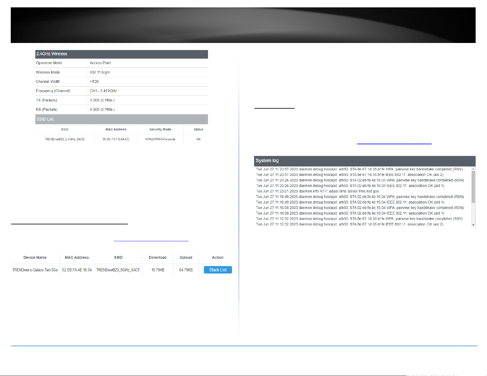
• SSID: Displays the SSID that the client is connected to
• Mode: Displays the 802.11 wireless mode and the channel width that the client
device is connected.
• Download (Bytes): Displays the amount of data transmitted to the client
• Upload (Bytes): Displays the amount of data received from the client
• Action: Clicking the Black List button will ban the client from the network
Indoor Wireless Access Points
System Log
Dashboard > System Log
System log keeps track of changes made to the access point.
• Operation Mode: Displays the current operating mode for each wireless band
• Wireless Mode: Displays the wireless mode set on each wireless band
• Channel Width: Displays the applied channel width
• Frequency (Channel): Displays the current operating wireless channel
• Tx/Rx Packets: Displays the Transmit (Tx) and Receive (Rx) packet rate
• SSID List: Displays the multiple SSID settings.
1. Log into your management page (see “Access the management page
2. Click on the Dashboard tab and click System Log.
” on page 13).
Check connected wireless clients
Dashboard > 2.4GHz Wireless / 5GHz Wireless
1. Log into your management page (see “Access the management page
2. Click on the Status tab and click 2.4GHz or 5GHz Wireless.
• Device Name: Displays the name of the client that is connected to the selected
band
• MAC Address: Displays the MAC address of the client that is connected to the
access point
© Copyright 2023 TRENDnet. All Rights Reserved.
” on page 16).
• Refresh: Clicking Refresh allows the access point to update the log with any
new data that has not been previously logged yet.
• Clear: Clears all the data saved previously onto the log.
35
Page 39
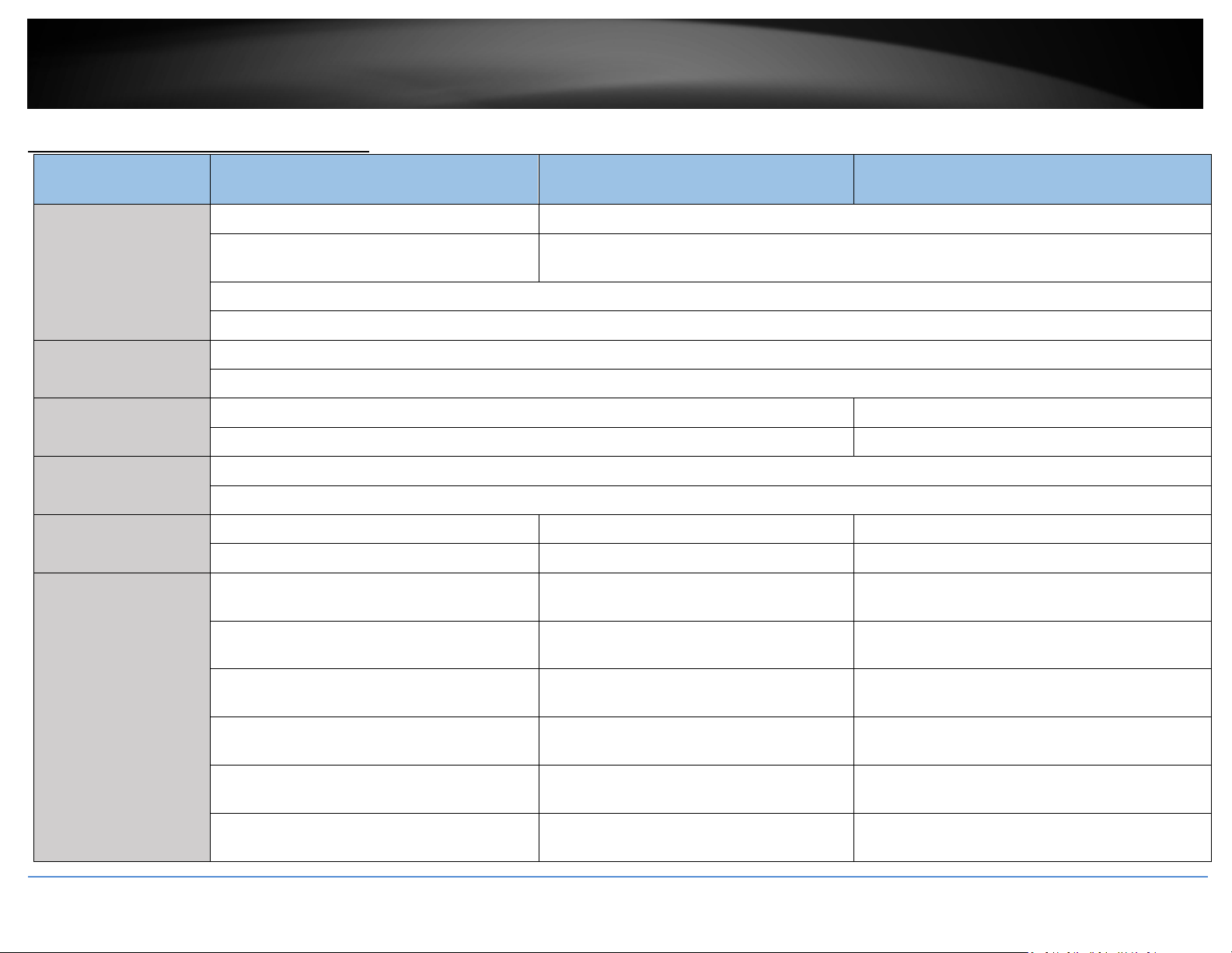
TRENDnet User’s Guide
Indoor Wireless Access Points
Hardware Features and Specifications
Power Port (12V DC, 1A external power adapter
Hardware Interface
Frequency
Wireless Channels
Modulation
Antenna Gain
TEW-823DAP (v1.0R) TEW-923DAP (v1.0R) TEW-925DAP (v1.0R)
1 x 802.3af PoE Gigabit LAN Port 1 x 802.3at PoE+ 2.5GBASE-T LAN port (power input)
Power port (12V DC, 1.5A external power adapter not included)
not included)
LED indicator
Reset button
2.4GHz: 2.412 – 2.472GHz
5GHz: 5.180 – 5.825GHz
2.4GHz: FCC: 1-11, ETSI: 1-13 2.4GHz: FCC: 1-11
5GHz: FCC: 36, 40, 44, 48, 149, 153, 157, 161, and 165; ETSI: 36, 40, 44, 48 5GHz: FCC: 36, 40, 44, 48, 149, 153, 157, 161, and 165
DBPSK/DQPSK/CCK for DSSS technique
BPSK/QPSK/16-QAM/64-QAM/256-QAM for OFDM technique
2.4GHz: 2 x 4 dBi internal 2.4GHz: 2 x 4.5 dBi internal 2.4GHz: 2 x 4.5 dBi internal
5GHz: 2 x 5 dBi internal 5GHz: 2 x 5.5 dBi internal 5GHz: 2 x 5 dBi internal
802.11a: FCC: 28.5 dBm (max.) / CE: 19 dBm
(max.)
802.11b: FCC: 26.5dBm (max.) / CE: 18 dBm
(max.)
802.11g: FCC: 30 dBm (max.) / CE: 19 dBm (max.) 802.11g: FCC: 22 dBm (max.) / CE: 22 dBm
Wireless Output Power
802.11n (2.4GHz): FCC: 24.5 dBm (max.) / CE: 21
dBm (max.)
802.11n (5GHz): FCC: 28.5 dBm (max.) / CE:
21dBm (max.)
802.11ac: FCC: 28.5 dBm (max.) / CE: 21 dBm
(max.)
© Copyright 2023 TRENDnet. All Rights Reserved.
802.11a: FCC: 23 dBm (max.) / CE: 23 dBm
(max.)
802.11b: FCC: 22 dBm (max.) / CE: 22 dBm
(max.)
(max.)
802.11n (2.4GHz): FCC: 22 dBm (max.) / CE: 22
dBm (max.)
802.11n (5GHz.): FCC: 23 dBm (max.) / CE: 23
dBm (max.)
802.11ac (5GHz.): FCC: 23 dBm (max.) / CE: 23
dBm (max.)
802.11a: FCC: 27 dBm (max
802.11b: FCC: 21 dBm (max.)
802.11g: FCC: 21 dBm (max.)
802.11n (2.4GHz): FCC: 21 dBm (max.)
802.11n (5GHz.): FCC: 27 dBm (max.)
802.11ac (5GHz.): FCC: 27 dBm (max.)
36
Page 40
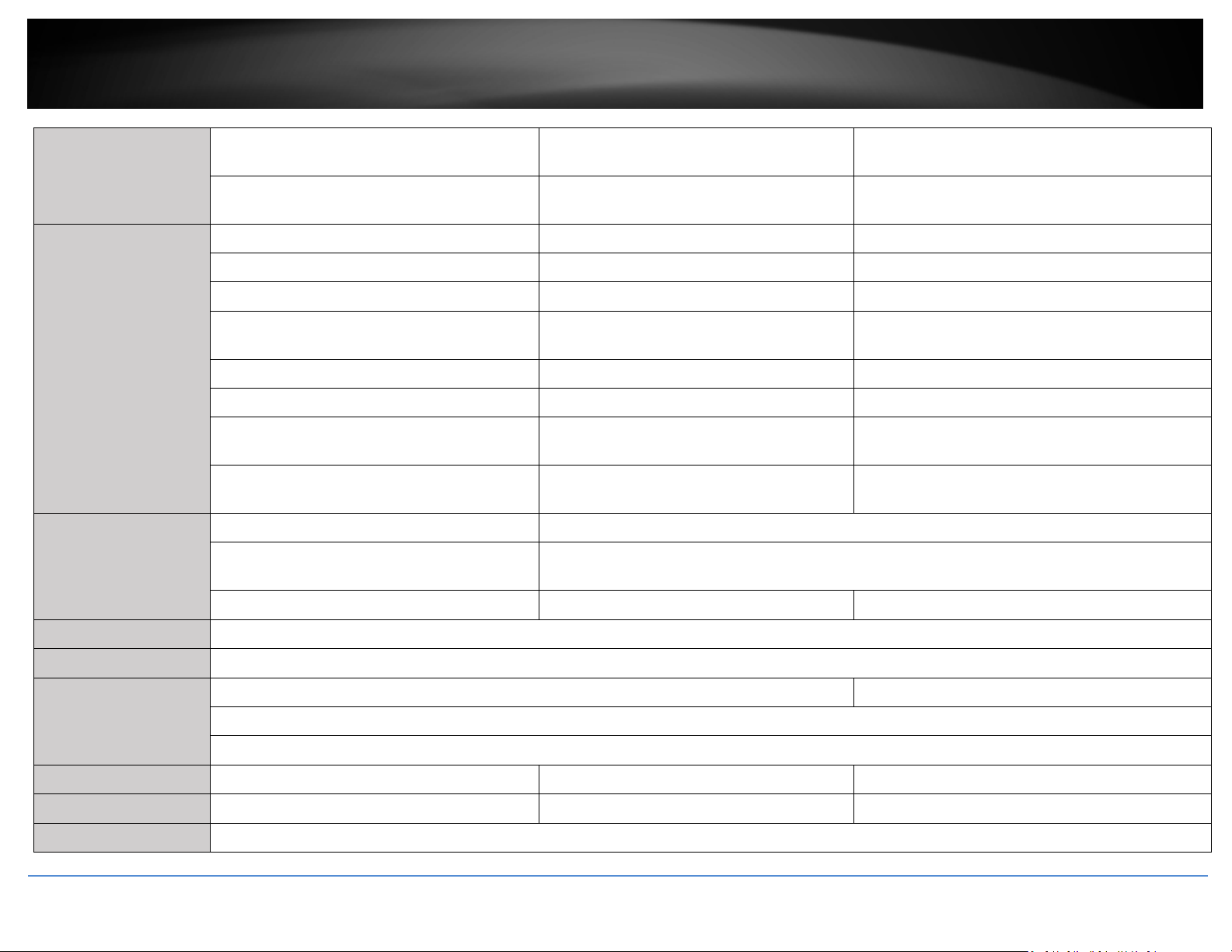
TRENDnet User’s Guide
Receiving Sensitivity
- 802.11ax (2.4GHz): FCC: 22 dBm (max.) / CE:
22 dBm (max.)
-
802.11a: -73 dBm (typical) @ 54Mbps 802.11a: -72 dBm (typical) @ 54Mbps 802.11a: -69 dBm (typical) @ 54Mbps
802.11b: -87 dBm (typical) @ 11Mbps 802.11b: -92 dBm (typical) @ 11Mbps 802.11b: -84 dBm (typical) @ 11Mbps
802.11g: -73 dBm (typical) @ 54Mbps 802.11g: -78 dBm (typical) @ 54Mbps 802.11g: -71 dBm (typical) @ 54Mbps
802.11n (2.4GHz): -68 dBm (typical) @ 400Mbps 802.11n (2.4GHz): -66 dBm (typical) @
802.11n (5GHz): -67 dBm (typical) @ 400Mbps 802.11n (5GHz): -64 dBm (typical) @ 300Mbps 802.11n (5GHz): -58 dBm (typical) @ 300Mbps
802.11ac: -57 dBm (typical) @ 867Mbps 802.11ac: -60 dBm (typical) @ 867Mbps 802.11ac: -57 dBm (typical) @ 1733Mbps
-
-
IEEE 802.3af Type 1 PoE PD Class 3 IEEE 802.3at Type 2 PoE+ PD Class 4
802.11ax (5GHz.): FCC: 23 dBm (max.) / CE: 23
dBm (max.)
300Mbps
802.11ax (2.4GHz): -64 dBm (typical) @
573Mbps
802.11ax (5GHz): -63 dBm (typical) @
2402Mbps
Indoor Wireless Access Points
802.11ax (2.4GHz): FCC: 21 dBm (max.)
802.11ax (5GHz.): FCC: 27 dBm (max.)
802.11n (2.4GHz): -67 dBm (typical) @ 300Mbps
802.11ax (2.4GHz): -54 dBm (typical) @ 573Mbps
802.11ax (5GHz): -52 dBm (typical) @ 4804Mbps
Power
Operating Temperature 0° - 40° C (32° - 104° F)
Operating Humidity Max. 90% non-condensing
Certifications
Dimensions 130 x 130 x 46mm (5.12 x 5.12 x 1.8 in.) 160 x 160 x 30mm (6.3 x 6.3 x 1.18 in.) 160 x 160 x 30mm (6.3 x 6.3 x 1.18in.)
Weight 188g (6.7 oz.) 380g (13.4 oz.) 600g (21.16 oz.)
Warranty 3 year
© Copyright 2023 TRENDnet. All Rights Reserved.
Input: 100 – 240 V AC, 50/60Hz, Output: 12V DC,
1A external power adapter (not included)
Max. consumption: 11.9W Max. consumption: 17.4W Max. Consumption: 18W
CE -
Input: 100 – 240V AC, 50/60Hz, Output: 12V DC, 1.5A external power adapter (not included)
FCC
IC
37
Page 41
TRENDnet User’s Guide
Package Content
TEW-823DAP TEW-923DAP TEW-925DAP
Quick Installation Guide
Network cable (0.5m / 1.64 ft.)
Mounting plates
Indoor Wireless Access Points
© Copyright 2023 TRENDnet. All Rights Reserved.
38
Page 42
TRENDnet User’s Guide
Indoor Wireless Access Points
Indoor Access Point Software Specifications
Standards
Features
Operation Modes
Management/Monitoring
• IEEE 802.3
• IEEE 802.3u
• IEEE 802.3x
• IEEE 802.3ab
• IEEE 802.3af
• IEEE 802.3at (TEW-923DAP / TEW-
925DAP)
• MU-MIMO
• IPv4 static/DHCP address assignment
• Access Point • Repeater
• Web based management (HTTP/HTTPS)
• Command Line Interface (Telnet/SSH)
• SNMP v2c/v3
• Spanning Tree Protocol (STP)
• IEEE 802.3bz (TEW-923DAP / TEW-
925DAP)
• IEEE 802.1Q
• IEEE 802.11a
• IEEE 802.11b
• IEEE 802.11g
• IEEE 802.11k
• IEEE 802.11n (up to 400Mbps)*
• Band steering
• UPnP Bonjour
• Event logging
• Ping test
• Traceroute
• Schedule WiFi radio enable/disable
• IEEE 802.11r
• IEEE 802.11v
• IEEE 802.11ac (up to 867Mbps / TEW-
925DAP: up to 1733Mbps)*
• IEEE 802.11ax
(TEW-923DAP: 5GHz up to 2402Mbps /
2.4GHz up to 573Mbps
TEW-925DAP: 5GHz up to 4804Mbps /
2.4GHz up to 573Mbps)*
• 802.1Q GLAN assignment per SSID
• Ping watchdog/gateway connection
monitor
• Reboot & schedule automatic reboot
• Channel utilization scan
• Wireless encryption: WPA2/WPA3-
Access Control
QoS
SSID
Disclaimer
*Maximum wireless signal rates are referenced from IEEE 802.11 theoretical specifications. Actual data throughput and coverage will vary depending on interference, network traffic,
building materials and other conditions. For maximum performance of up to 867Mbps use with an 867Mbps 802.11ac wireless adapter. For maximum performance of up to 300Mbps,
use with a 300Mbps 802.11n wireless adapter. Multi-User MIMO (MU-MIMO) requires the use of multiple MU-MIMO enabled wireless adapters.
**Due to regulatory requirements, the wireless channels specified cannot be statically assigned, but will be available within the available wireless channels when set to auto.
© Copyright 2023 TRENDnet. All Rights Reserved.
RADIUS (Enterprise), WPA2/WPA3-PSK
(Personal)
• Bandwidth control per SSID
• Up to 8 SSIDs per wireless band (16
total)
• MAC filter with scheduling
• Maximum client limit
• Client isolation
39
Page 43

TRENDnet User’s Guide
Troubleshooting
Q: I typed http://192.168.10.1 in my Internet Browser Address Bar, but an error
message says “The page cannot be displayed.” How can I access the access point
management page?
Answer:
1. Check your hardware settings again. See “Getting Started
2. Make sure the LAN and WLAN lights are lit.
3. Make sure your network adapter TCP/IP settings are set to Obtain an IP address
automatically or DHCP (see the steps below).
4. Make sure your computer is connected to one of the router’s LAN ports
5. Press on the factory reset button for 15 seconds, the release.
Windows 11/10/8.1/8/7
a. Go into the Control Panel, click Network and Sharing Center.
b. Click Change Adapter Settings, right-click the Local Area Connection icon.
c. Then click Properties and click Internet Protocol Version 4 (TCP/IPv4).
d. Then click Obtain an IP address automatically and click OK.
Windows Vista
a. Go into the Control Panel, click Network and Internet.
b. Click Manage Network Connections, right-click the Local Area Connection
icon and click Properties.
c. Click Internet Protocol Version (TCP/IPv4) and then click Properties.
d. Then click Obtain an IP address automatically and click OK.
Windows XP/2000
a. Go into the Control Panel, double-click the Network Connections icon
b. Right-click the Local Area Connection icon and the click Properties.
c. Click Internet Protocol (TCP/IP) and click Properties.
d. Then click Obtain an IP address automatically and click OK.
Note: If you are experiencing difficulties, please contact your computer or operating
system manufacturer for assistance.
Q: I am not sure what type of Internet Account Type I have for my Cable/DSL
connection. How do I find out?
Answer:
Contact your Internet Service Provider (ISP) for the correct information.
Q: The Wizard does not appear when I access the access point. What should I do?
” on page 7.
Answer:
1. Click on Wizard on the left-hand side.
2. Near the top of the browser, “Pop-up blocked” message may appear. Right click on
the message and select Always Allow Pop-ups from This Site.
3. Disable your browser's pop up blocker.
Q: I went through the Wizard, but I cannot get onto the Internet. What should I do?
Answer:
1. Verify that you can get onto the Internet with a direct connection into your modem
(meaning plug your computer directly to the modem and verify that your single
computer (without the help of the router) can access the Internet).
2. Power cycle your modem and router. Unplug the power to the modem and router.
Wait 30 seconds, and then reconnect the power to the modem. Wait for the modem to
fully boot up, and then reconnect the power to the router.
3. Contact your ISP and verify all the information that you have in regards to your
Internet connection settings is correct.
Q: I cannot connect wirelessly to the access point. What should I do?
Answer:
1. Double check that the LAN light on the access point is lit.
2. Power cycle the router. Unplug the power to the router. Wait 15 seconds, then plug
the power back in to the router.
3. Contact the manufacturer of your wireless network adapter and make sure the
wireless network adapter is configured with the proper SSID. The preset SSID is
TRENDnet (model_number).
4. To verify whether or not wireless is enabled, login to the router management page,
click on Wireless.
5. Please see “Steps to improve wireless connectivity
wireless connectivity problems.
Indoor Wireless Access Points
” on page 8 if you continue to have
© Copyright 2023 TRENDnet. All Rights Reserved.
40
Page 44

TRENDnet User’s Guide
Appendix
How to find your IP address?
Note: Please note that although the following procedures provided to follow for your
operating system on configuring your network settings can be used as general
guidelines, however, it is strongly recommended that you consult your computer or
operating system manufacturer directly for assistance on the proper procedure for
configuring network settings.
Command Prompt Method
Windows 2000/XP/Vista/7/8/8.1/10/11
1. On your keyboard, press Windows Logo + R keys simultaneously to bring up the Run
dialog box.
2. In the dialog box, type cmd to bring up the command prompt.
3. In the command prompt, type ipconfig /all to display your IP address settings.
MAC OS X
1. Navigate to your Applications folder and open Utilities.
2. Double-click on Terminal to launch the command prompt.
3. In the command prompt, type ipconfig getifaddr <en0 or en1> to display the wired
or wireless IP address settings.
Note: en0 is typically the wired Ethernet and en1 is typically the wireless Airport
interface.
Graphical Method
MAC OS 10.6 – 10.12
1. From the Apple menu, select System Preferences.
2. In System Preferences, from the View menu, select Network.
3. In the Network preference window, click a network port (e.g., Ethernet, AirPort,
modem). If you are connected, you'll see your IP address settings under "Status:"
MAC OS 10.4
1. From the Apple menu, select Location, and then Network Preferences.
2. In the Network Preference window, next to "Show:", select Network Status. You'll see
your network status and your IP address settings displayed.
© Copyright 2023 TRENDnet. All Rights Reserved.
Note: If you are experiencing difficulties, please contact your computer or operating
system manufacturer for assistance.
How to configure your network settings to obtain an IP address automatically or use
DHCP?
Note: Please note that although the following procedures provided to follow for your
operating system on configuring your network settings can be used as general
guidelines, however, it is strongly recommended that you consult your computer or
operating system manufacturer directly for assistance on the proper procedure for
configuring network settings.
Windows 7 and up
a. Go into the Control Panel, click Network and Sharing Center.
b. Click Change Adapter Settings, right-click the Local Area Connection icon.
c. Then click Properties and click Internet Protocol Version 4 (TCP/IPv4).
d. Then click Obtain an IP address automatically and click OK.
Windows Vista
a. Go into the Control Panel, click Network and Internet.
b. Click Manage Network Connections, right-click the Local Area Connection
icon and click Properties.
c. Click Internet Protocol Version (TCP/IPv4) and then click Properties.
d. Then click Obtain an IP address automatically and click OK.
Windows XP/2000
a. Go into the Control Panel, double-click the Network Connections icon
b. Right-click the Local Area Connection icon and the click Properties.
c. Click Internet Protocol (TCP/IP) and click Properties.
d. Then click Obtain an IP address automatically and click OK.
MAC OS 10.4/10.5/10.6
a. From the Apple, drop-down list, select System Preferences.
b. Click the Network icon.
c. From the Location drop-down list, select Automatic.
d. Select and view your Ethernet connection.
In MAC OS 10.4, from the Show drop-down list, select Built-in Ethernet and
select the TCP/IP tab.
In MAC OS 10.5/10.6, in the left column, select Ethernet.
e. Configure TCP/IP to use DHCP.
Indoor Wireless Access Points
41
Page 45

TRENDnet User’s Guide
In MAC 10.4, from the Configure IPv4, drop-down list, select Using DHCP and
click the Apply Now button.
In MAC 10.5, from the Configure drop-down list, select Using DHCP and click
the Save button.
In MAC 10.6, from the Configure drop-down list, select Using DHCP and click
the Save button.
f. Restart your computer.
Note: If you are experiencing difficulties, please contact your computer or operating
system manufacturer for assistance.
How to find your MAC address?
In Windows 2000/XP/Vista/7/8/8.1/10,
Your computer MAC addresses are also displayed in this window, however, you can type
getmac –v to display the MAC addresses only.
In MAC OS 10.4,
1. Apple Menu > System Preferences > Network
2. From the Show menu, select Built-in Ethernet.
3. On the Ethernet tab, the Ethernet ID is your MAC Address.
In MAC OS 10.5/10.6,
1. Apple Menu > System Preferences > Network
2. Select Ethernet from the list on the left.
3. Click the Advanced button.
3. On the Ethernet tab, the Ethernet ID is your MAC Address.
How to connect to a wireless network using the built-in Windows utility?
Note: Please note that although the following procedures provided to follow for your
operating system on configuring your network settings can be used as general
guidelines, however, it is strongly recommended that you consult your computer or
operating system manufacturer directly for assistance on the proper procedure for
connecting to a wireless network using the built-in utility.
Windows 7/8/8.1/10/11
1. Open Connect to a Network by clicking the network icon (
notification area.
2. In the list of available wireless networks, click the wireless network you would like to
connect to, then click Connect.
4. You may be prompted to enter a security key in order to connect to the network.
5. Enter in the security key corresponding to the wireless network, and click OK.
Windows Vista
1. Open Connect to a Network by clicking the Start Button.
To.
2. In the Show list, click Wireless.
3. In the list of available wireless networks, click the wireless network you would like to
connect to, then click Connect.
4. You may be prompted to enter a security key in order to connect to the network.
5. Enter in the security key corresponding to the wireless network, and click OK.
Windows XP
1. Right-click the network icon in the notification area, then click View Available
Wireless Networks.
2. In Connect to a Network, under Available Networks, click the wireless network you
would like to connect to.
3. You may be prompted to enter a security key in order to connect to the network.
4. Enter in the security key corresponding to the wireless network, and click Connect.
Indoor Wireless Access Points
or ) in the
and then click Connect
© Copyright 2023 TRENDnet. All Rights Reserved.
42
Page 46
TRENDnet User’s Guide
Indoor Wireless Access Points
Federal Communication Commission Interference Statement
This equipment has been tested and found to comply with the limits for a Class B digital
device, pursuant to Part 15 of the FCC Rules. These limits are designed to provide reasonable
protection against harmful interference in a residential installation. This equipment
generates, uses and can radiate radio frequency energy and, if not installed and used in
accordance with the instructions, may cause harmful interference to radio communications.
However, there is no guarantee that interference will not occur in a particular installation. If
this equipment does cause harmful interference to radio or television reception, which can
be determined by turning the equipment off and on, the user is encouraged to try to correct
the interference by one of the following measures:
• Reorient or relocate the receiving antenna.
• Increase the separation between the equipment and receiver.
• Connect the equipment into an outlet on a circuit different from that to which the
receiver is connected.
• Consult the dealer or an experienced radio/TV technician for help.
FCC Caution: Any changes or modifications not expressly approved by the party responsible
for compliance could void the user's authority to operate this equipment.
This device complies with Part 15 of the FCC Rules. Operation is subject to the following two
conditions: (1) This device may not cause harmful interference, and (2) this device must
accept any interference received, including interference that may cause undesired
operation.
IMPORTANT NOTE:
Radiation Exposure Statement:
This equipment complies with FCC radiation exposure limits set forth for an uncontrolled
environment. This equipment should be installed and operated with minimum distance
20cm between the radiator & your body.
This transmitter must not be co-located or operating in conjunction with any other antenna
or transmitter.
Country Code selection feature to be disabled for products marketed to the US/CANADA
Europe – EU Declaration of Conformity
TRENDnet hereby declare that the product is in compliance with the essential requirements
and other relevant provisions under our sole responsibility.
Safety
EN IEC 62368-1:2020 + A11: 2020
EMC
EN 55032: 2015 / AC: 2016
EN 55035: 2017
EN 301 489-1 V2.2.1 (2017-03)
EN 301 489-17 V3.2.0 (2017-03)
Radio Spectrum & Health
EN 300 328 V2.2.2 (2019-07)
EN 301 893 V2.1.1 (2017-05)
EN IEC 62311:2020
EN 50385: 2017 / EN 50665: 2017
Energy Efficiency
Regulation (EC) No. 1275/2008, Regulation, No. 278/2009, No. 801/2013
This product is herewith confirmed to comply with the Directives.
Directives
EMC Directive 2014/30/EU
RoHS 2011/65/EU
WEEE Directive 2012/19/EU
REACH Regulation (EC) No.1907/2006
Low Voltage Directive 2014/35/EU
Radio Equipment Directive 2014/53/EU
Ecodesign Directive 2009/125/EC
Operations in the 5.15-5.25GHz / 5.470 ~ 5.725GHz band are restricted to indoor usage only.
The band from 5600-5650MHz will be disabled by the software during the manufacturing
and cannot be changed by the end user. This device meets all the other requirements
specified in Part 15E, Section 15.407 of the FCC Rules.
© Copyright 2023 TRENDnet. All Rights Reserved.
43
Page 47

TRENDnet User’s Guide
Limited Warranty
Industry Canada Statement
This device contains licence-exempt transmitter(s)/receiver(s) that comply with Innovation,
Science and Economic Development Canada’s licence-exempt RSS(s). Operation is subject to
the following two conditions:
(1) This device may not cause interference
(2) This device must accept any interference, including interference that may cause
undesired operation of the device
L’émetteur/récepteur exempt de licence contenu dans le présent appareil est conforme aux
CNR d’Innovation, Sciences et Développement économique Canada applicables aux appareils
radio exempts de licence. L’exploitation est autorisée aux deux conditions suivantes :
(1) L’appareil ne doit pas produire de brouillage;
(2) L’appareil doit accepter tout brouillage radioélectrique subi, même si le brouillage est
susceptible d’en compromettre le fonctionnement.
Caution:
the device for operation in the band 5150–5250 MHz is only for indoor use to reduce the
potential for harmful interference to co-channel mobile satellite systems;
Avertissement:
les dispositifs fonctionnant dans la bande de 5150 à 5250MHz sont réservés uniquement
pour une utilisation à l'intérieur afin de réduire les risques de brouillage préjudiciable aux
systèmes de satellites mobiles utilisant les mêmes canaux;
Radiation Exposure Statement:
This equipment complies with Canada radiation exposure limits set forth for an uncontrolled
environment. This equipment should be installed and operated with minimum distance
20cm between the radiator & your body.
Déclaration d'exposition aux radiations:
Cet équipement est conforme Canada limites d'exposition aux radiations dans un
environnement non contrôlé. Cet équipement doit être installé et utilisé à distance minimum
de 20cm entre le radiateur et votre corps.
Federal Communication Commission Interference Statement
This equipment has been tested and found to comply with the limits for a Class B digital
device, pursuant to Part 15 of the FCC Rules. These limits are designed to provide reasonable
protection against harmful interference in a residential installation. This equipment
generates, uses and can radiate radio frequency energy and, if not installed and used in
accordance with the instructions, may cause harmful interference to radio communications.
However, there is no guarantee that interference will not occur in a particular installation. If
this equipment does cause harmful interference to radio or television reception, which can
be determined by turning the equipment off and on, the user is encouraged to try to correct
the interference by one of the following measures:
- Reorient or relocate the receiving antenna.
- Increase the separation between the equipment and receiver.
- Connect the equipment into an outlet on a circuit different from that to which the receiver
is connected.
- Consult the dealer or an experienced radio/TV technician for help.
FCC Caution: Any changes or modifications not expressly approved by the party responsible
for compliance could void the user's authority to operate this equipment.
This device complies with Part 15 of the FCC Rules. Operation is subject to the following two
conditions: (1) This device may not cause harmful interference, and (2) this device must
accept any interference received, including interference that may cause undesired
operation.
IMPORTANT NOTE:
Radiation Exposure Statement:
This equipment complies with FCC radiation exposure limits set forth for an uncontrolled
environment. This equipment should be installed and operated with minimum distance
20cm between the radiator & your body.
This transmitter must not be co-located or operating in conjunction with any other antenna
or transmitter.
Country Code selection feature to be disabled for products marketed to the US/CANADA
Operation of this device is restricted to indoor use only
© Copyright 2023 TRENDnet. All Rights Reserved.
44
Page 48

TRENDnet User’s Guide
Limited Warranty
TRENDnet warrants only to the original purchaser of this product from a TRENDnet
authorized reseller or distributor that this product will be free from defects in material
and workmanship under normal use and service. This limited warranty is non-
transferable and does not apply to any purchaser who bought the product from a
reseller or distributor not authorized by TRENDnet, including but not limited to
purchases from Internet auction sites.
Limited Warranty
TRENDnet warrants its products against defects in material and workmanship, under
normal use and service. Specific warranty periods are listed on each of the respective
product pages on the TRENDnet website.
• AC/DC Power Adapter, Cooling Fan, and Power Supply carry a one-year
warranty.
Limited Lifetime Warranty
TRENDnet offers a limited lifetime warranty for all of its metal-enclosed network
switches that have been purchased in the United States/Canada on or after 1/1/2015.
• Cooling fan and internal power supply carry a one-year warranty
To obtain an RMA, the ORIGINAL PURCHASER must show Proof of Purchase and return
the unit to the address provided. The customer is responsible for any shipping-related
costs that may occur. Replacement goods will be shipped back to the customer at
TRENDnet’s expense.
Upon receiving the RMA unit, TRENDnet may repair the unit using refurbished parts. In
the event that the RMA unit needs to be replaced, TRENDnet may replace it with a
refurbished product of the same or comparable model.
In the event that, after evaluation, TRENDnet cannot replace the defective product or
there is no comparable model available, we will refund the depreciated value of the
product.
If a product does not operate as warranted during the applicable warranty period,
TRENDnet shall reserve the right, at its expense, to repair or replace the defective
product or part and deliver an equivalent product or part to the customer. The
repair/replacement unit's warranty continues from the original date of purchase. All
products that are replaced become the property of TRENDnet. Replacement products
may be new or reconditioned. TRENDnet does not issue refunds or credit. Please
contact the point-of-purchase for their return policies.
TRENDnet shall not be responsible for any software, firmware, information, or memory
data of customer contained in, stored on, or integrated with any products returned to
TRENDnet pursuant to any warranty.
There are no user serviceable parts inside the product. Do not remove or attempt to
service the product by any unauthorized service center. This warranty is voided if (i) the
product has been modified or repaired by any unauthorized service center, (ii) the
product was subject to accident, abuse, or improper use, or (iii) the product was subject
to conditions more severe than those specified in the manual.
Warranty service may be obtained by contacting TRENDnet within the applicable
warranty period and providing a copy of the dated proof of the purchase. Upon proper
submission of required documentation, a Return Material Authorization (RMA) number
will be issued. An RMA number is required in order to initiate warranty service support
for all TRENDnet products. Products that are sent to TRENDnet for RMA service must
have the RMA number marked on the outside of return packages and sent to TRENDnet
prepaid, insured and packaged appropriately for safe shipment. International customers
Limited Warranty
© Copyright 2023 TRENDnet. All Rights Reserved.
45
Page 49

TRENDnet User’s Guide
shipping from outside of the USA and Canada are responsible for any return shipping
and/or customs charges, including but not limited to, duty, tax, and other fees.
Refurbished product: Refurbished products carry a 90-day warranty after date of
purchase. Please retain the dated sales receipt with purchase price clearly visible as
evidence of the original purchaser's date of purchase. Replacement products may be
refurbished or contain refurbished materials. If TRENDnet, by its sole determination, is
unable to replace the defective product, we will offer a refund for the depreciated value
of the product.
WARRANTIES EXCLUSIVE: IF THE TRENDNET PRODUCT DOES NOT OPERATE AS
WARRANTED ABOVE, THE CUSTOMER'S SOLE REMEDY SHALL BE, AT TRENDNET'S
OPTION, REPAIR OR REPLACE. THE FOREGOING WARRANTIES AND REMEDIES ARE
EXCLUSIVE AND ARE IN LIEU OF ALL OTHER WARRANTIES, EXPRESSED OR IMPLIED,
EITHER IN FACT OR BY OPERATION OF LAW, STATUTORY OR OTHERWISE, INCLUDING
WARRANTIES OF MERCHANTABILITY AND FITNESS FOR A PARTICULAR PURPOSE.
TRENDNET NEITHER ASSUMES NOR AUTHORIZES ANY OTHER PERSON TO ASSUME FOR
IT ANY OTHER LIABILITY IN CONNECTION WITH THE SALE, INSTALLATION,
MAINTENANCE, OR USE OF TRENDNET'S PRODUCTS.
TRENDNET SHALL NOT BE LIABLE UNDER THIS WARRANTY IF ITS TESTING AND
EXAMINATION DISCLOSE THAT THE ALLEGED DEFECT IN THE PRODUCT DOES NOT EXIST
OR WAS CAUSED BY CUSTOMER'S OR ANY THIRD PERSON'S MISUSE, NEGLECT,
IMPROPER INSTALLATION OR TESTING, UNAUTHORIZED ATTEMPTS TO REPAIR OR
MODIFY, OR ANY OTHER CAUSE BEYOND THE RANGE OF THE INTENDED USE, OR BY
ACCIDENT, FIRE, LIGHTNING, OR OTHER HAZARD.
CONTRACT OR TORT (INCLUDING NEGLIGENCE), FOR INCIDENTAL, CONSEQUENTIAL,
INDIRECT, SPECIAL, OR PUNITIVE DAMAGES OF ANY KIND, OR FOR LOSS OF REVENUE OR
PROFITS, LOSS OF BUSINESS, LOSS OF INFORMATION OR DATE, OR OTHER FINANCIAL
LOSS ARISING OUT OF OR IN CONNECTION WITH THE SALE, INSTALLATION,
MAINTENANCE, USE, PERFORMANCE, FAILURE, OR INTERRUPTION OF THE POSSIBILITY
OF SUCH DAMAGES, AND LIMITS ITS LIABILITY TO REPAIR, REPLACEMENT, OR REFUND
OF THE PURCHASE PRICE PAID, AT TRENDNET'S OPTION. THIS DISCLAIMER OF LIABILITY
FOR DAMAGES WILL NOT BE AFFECTED IF ANY REMEDY PROVIDED HEREIN SHALL FAIL
OF ITS ESSENTIAL PURPOSE.
Governing Law: This Limited Warranty shall be governed by the laws of the state of
California.
Some TRENDnet products include software code written by third party developers.
These codes are subject to the GNU General Public License ("GPL") or GNU Lesser
General Public License ("LGPL").
Visit http://www.trendnet.com/gpl or the support section on
http://www.trendnet.com and search for the desired TRENDnet product to access to
the GPL Code or LGPL Code. These codes are distributed WITHOUT WARRANTY and are
subject to the copyrights of the developers. TRENDnet does not provide technical
support for these codes. Please visit http://www.gnu.org/licenses/gpl.txt or
http://www.gnu.org/licenses/lgpl.txt for specific terms of each license.
PWP07172015v3 2023/6/30
Limited Warranty
LIMITATION OF LIABILITY: TO THE FULL EXTENT ALLOWED BY LAW, TRENDNET ALSO
EXCLUDES FOR ITSELF AND ITS SUPPLIERS ANY LIABILITY, WHETHER BASED IN
© Copyright 2023 TRENDnet. All Rights Reserved.
46
Page 50

 Loading...