

1

Federal Communication Commission Interference Statement
This equipment has been tested and found to comply with the limits for a Class B digital device,
pursuant to Part 15 of the FCC Rules. These limits are designed to provide reasonable protection
against harmful interference in a residential installation. This equipment generates, uses and can
radiate radio frequency energy and, if not installed and used in accordance with the instructions,
may cause harmful interference to radio communications. However, there is no guarantee that
interference will not occur in a particular installation. If this equipment does cause harmful
interference to radio or television reception, which can be determined by turning the equipment off
and on, the user is encouraged to try to correct the interference by one of the following measures:
- Reorient or relocate the receiving antenna.
- Increase the separation between the equipment and receiver.
- Connect the equipment into an outlet on a circuit different from that
to which the receiver is connected.
- Consult the dealer or an experienced radio/TV technician for help.
FCC Caution: Any changes or modifications not expressly approved by the party responsible for
compliance could void the user's authority to operate this equipment.
This device complies with Part 15 of the FCC Rules. Operation is subject to the following two
conditions: (1) This device may not cause harmful interference, and (2) this device must accept any
interference received, including interference that may cause undesired operation.
IMPORTANT NOTE:
FCC Radiation Exposure Statement:
This device complies with FCC RF Exposure limits set forth for an uncontrolled environment, under
47 CFR 2.1093 paragraph (d)(2).
This transmitter must not be co-located or operating in conjunction with any other antenna or
transmitter.
This device was tested for typical by stander conditions that may occur during use. To comply with
FCC RF exposure requirements a minimum separation distance of 1.5cm must be maintained
between the user’s body and the device, including the antenna.
2

CE Mark Warning
This is a Class B product. In a domestic environment, this product may cause radio interference, in
which case the user may be required to take adequate measures.
This transmitter must not be co-located or operation in conjunction with any other antenna or
transmitter.
3

Table of Contents
Federal Communications Commission (FCC) Interference statement 2
CE Mark Warning 3
Chapter 1 - Getting Started
1.1 About Your 802.11b/g WLAN USB Adapter 5
1.2 Package Content 5
1.3 System Requirement 5
1.4 LED Definition 6
1.5 Adapter Hardware and Utility Installation 6
1.6 Using the Utility to Configure Your Network 10
Chapter 2 – Maintenance
2.1 The Version Screen 19
2.2 Uninstall the Client Utility 19
2.3 Upgrading the Wireless Utility 19
4

Chapter 1 - Getting Started
This chapter introduces the Adapter and prepares you to use the Wireless Utility.
1.1 About Your 802.11b/g WLAN USB Adapter
The TEW-444UB is an IEEE 802.11b, and 802.11g compliant wireless LAN adapter. With the
Adapter, you can enjoy wireless mobility within almost any wireless networking environment.
The following lists the main features of your Adapter.
9 Your Adapter can communicate with other IEEE 802.11b/g compliant wireless devices.
9 Automatic rate selection.
9 Standard data transmission rates up to 54 Mbps.
9 Proprietary Super G transmission rate of 108 Mbps
9 Offers 64-bit, 128-bit and 152-bit WEP (Wired Equivalent Privacy) data encryption for
network security.
9 Supports IEEE 802.1x and WPA (Wi-Fi Protected Access).
9 Low CPU utilization allowing more computer system reso urces for other programs.
9 A built-in antenna.
9 Driver support for Windows 98SE/ME/2000/XP
1.2 Package Content
¾ 802.11b/g WLAN USB Adapter
¾ Installation and Manual CD
¾ Multilanguage Quick Installation Guide
¾ 1 x USB 2.0 Cable (102mm/4inches)
¾ Power Adapter
1.3 System Requirement
z Pentium class notebook computers with at least one available USB 2.0 port
z Microsoft Windows 98SE, ME, 2000 or XP
z CD-ROM drive
5
1.4 LED Definition
The following table describes the LED on the 802.11b/g WLAN USB Adapter
LED COLOR STATUS DESCRIPTION
OFF The Adapter has no connection
LINK Green
Blinking Slowly The Adapter is co nnected
Blinking The Adapter is se nding or receiving data
1.5 Adapter Hardware and Utility Installation
NOTE: If you have connected the USB Adapter to your computer, please
remove it first.
Follow the instructions below to install the USB Adapter and Utility.
STEP 1
Insert the Driver and Utility CD into CD drive
STEP 2
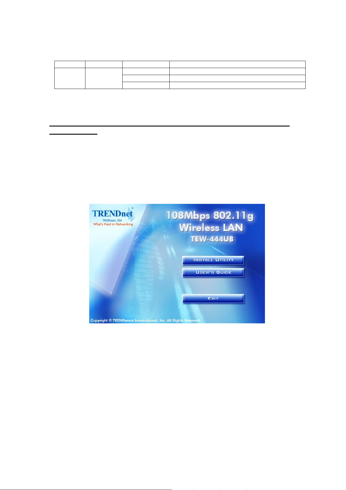
If your CD Autorun is ena bled, the Main Installation Menu will show. (Otherwise browse your CD
folder and double-click on the “setup.exe” file)
6
STEP 3
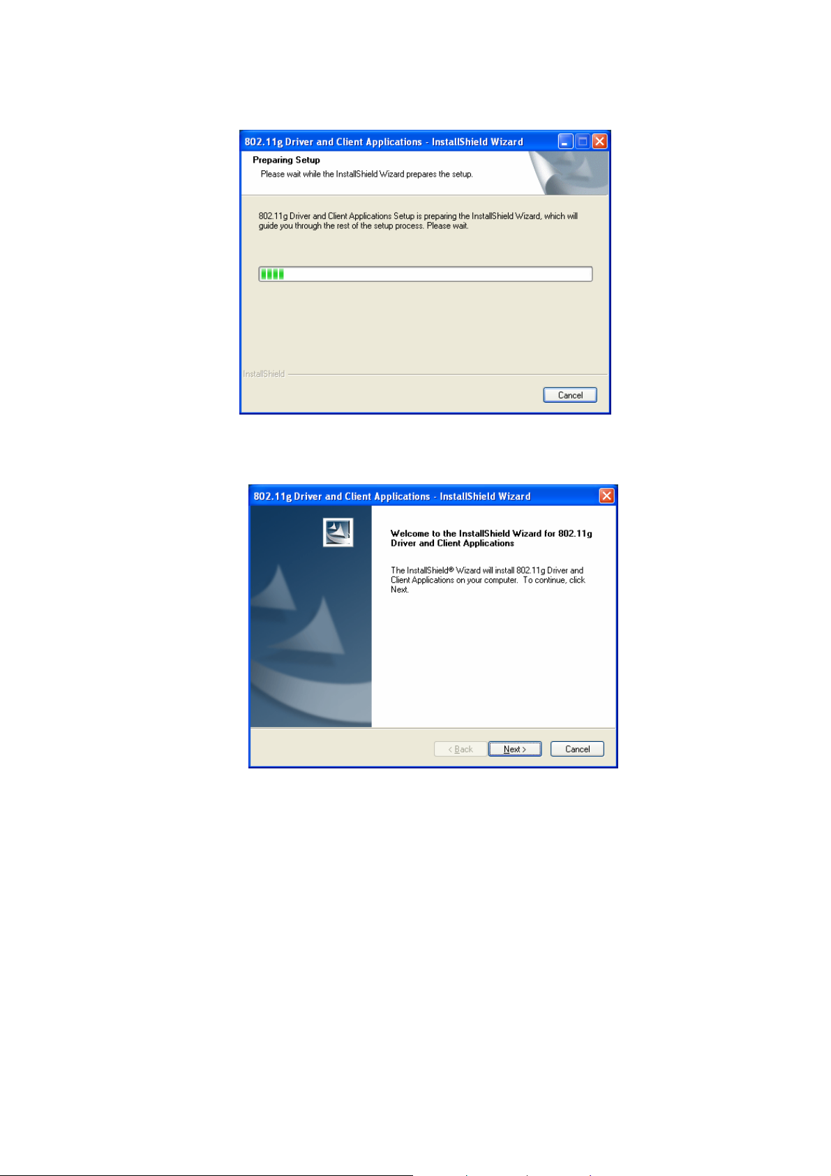
Click the Install Utility option. The InstallShield Wizard prepares for installation.
STEP 4
The InstallShield Wizard prompts you for confirm ation. Click Next on the following menu.
7

STEP 5
Click Next to continue
STEP 6
Click Install to start the installation process.
8

STEP 7
The utility will install the necessary files to your PC
STEP 8
Click Finish to complete the Driver and Client application installation.
9

STEP 9
Plug the TEW-444UB Wireless USB 2.0 Adapter into your PC’s USB port.
Windows will prompt the Found New Hardware message and the driver will load automatically.
STEP 10
After the driver is loaded properly, The Client Utility icon resides on the Desktop at the System
Tray automatically.
1.6 Using the Utility to Configure Your Network
The following are explanations on how to configure and use the Utility program. After completing
the installation procedure, a new icon as shown below will automatically appear on the desktop.
10

Double click on the icon and the 802.11b/g Client Utility window as shown below will appear.
The user can now use any of the management functions available in the 802.11b/g Client Utility.
Current Status
The Current Status tab contains general information about the program and its operations. The
Current Status tab does not require any configuration.
The following table describes the items found on the Current Status screen.
Profile Name
Link Status
Wireless Mode
IP Address
Network Type
The name of the current selected configuration profile. Set up the
configuration name on the General tab
.
Shows whether the station is associated to the wireless network.
Displays the wireless mode
Advanced tab
.
Displays the Computer's IP address.
The type of network
the station is connected to. The options include:
. Configure the wireless mode on the
Infrastructure (access point)
Ad Hoc
11

Configure the network type on the Advanced tab.
Current Channel
Server Based
Shows the currently connected channel.
Shows whether server based authentication is used.
Authentication
Data Encryption
Signal Strength
Displays the encryption type the driver is using. Configure the
encryption type on the Security tab
Shows the strength of the signal.
.
Click the Advanced button under Current Status section to see the advanced status diagnostics.
Advanced Status Information
Click the Advanced button on the Current Status tab of the Client Utility to see advanced
information about the program and its operations. The Current Status tab does not require any
configuration.
The following table describes the items found on the Advanced Status screen.
Network Name
(SSID)
Server Based
Displays the wireless network name.
Configure the network name on the General tab.
Shows whether server based authentication is used.
12

Authentication
Data Encryption
Authentication Type
Displays the encryption type the driver is using.
encryption type on the Security tab
Displays the authentication mode
.
.
Configure the
Configure the authentication mode on the General tab.
Message Integrity
Check
Associated AP
Name
Associated AP IP
Address
Associated AP MAC
Address
Power Save Mode
Current Power
Level
Available Power
Levels
Current Signal
Strength
Current Noise Level
Up Time
802.11b Preamble
Shows whether MIC
encrypted packets.
is enabled. MIC prevents bit-flip attacks on
Displays the name of the access point the wireless adapter is
associated to.
Shows the IP address of the access point the wireless adapter is
associated to.
Displays the MAC address of the access point the wireless adapter is
associated to.
Shows the power save mode
. Power management is disabled in ad
hoc mode.
Configure the power save mode on the Advanced tab.
Displays the transmit power level
Configure the transmit power level on the Advanced tab
Shows the 802.11b/g available power levels.
Shows the current signal strength in dBm.
Displays the current noise level in dBm.
rate in mW.
.
Shows how long the client adapter has been receiving power (in
hours:minutes:seconds). If the adapter runs for more than 24 hours,
the display shows in days:hours:minutes:seconds.
Displays the 802.11b preamble
format.
Configure the preamble format on the Advanced tab.
Current Receive
Current Tr ansmit
Channel
Frequency
Shows the current receive rate in Mbps.
Rate
Displays the current transmit rate in Mbps.
Rate
Shows the current connected channel.
Displays frequency the station is using.
13

Channel Set
Shows the current channel set.
Create or Modify a Configuration Profile
To add a new configuration profile, click New on the Profile Management tab. To modify a
configuration profile, select the configuration from the Profile list and click the Modify button.
The Profile Management dialog box displays the General tab
.
Profile Management:
Edit the General tab.
Edit the Security tab.
Edit the Advanced tab.
To configure a profile for ad hoc or access point (infrastructure) mode, edit the Network Type field
on the Advanced tab.
Note that the ACU only allows the creation of 16 configuration profiles. After the creation of 16
profiles, clicking the New button displays an error message. Remove
existing profile for a new use.
an old profile or modify an
Auto Profile Selection Management
Including a profile in the auto selection feature allows the wireless adapter to automatically select
that profile from the list of profiles and use it to connect to the network.
Including a profile in auto profile selection:
1. On the Profile Management tab, click the Order Profiles button.
2. The Auto Profile Selectio n Management window appears, with a list of all created profiles
in the Available Profiles box.
3. Highlight the profiles to add to auto profile selection, and then click Add. The profiles
appear in the Auto Selected Profiles box.
Ordering the auto selected profiles:
Highlight a profile in the Auto Selected Profiles box.
1.
2. Click Move Up, Move Down, or Remove as appropriate.
14

The first profile in the Auto Selected Profiles box has highest priority, and the last profile
has lowest priority.
3. Click OK.
4. Check the Auto Select Profiles box.
5. Save the modified configuration file.
When auto profile selection is enabled by checking Auto Select Profiles on the Profile
Management tab, the client adapter scans for an available network. The profile with the
highest priority and the same SSID as one of the found networks is the one that is used to
connect to the network. If the connection fails, the client adapter tries the next highest
priority profile that matches the SSID, and so on.
With auto profile selection enabled, the wireless adapter scans for available networks. The highest
priority profile with the same SSID as a found network is used to connect to the network. On a
failed connection, the client adapter tries with the next highest priority profile.
15

Scan Available Networks
Click the Scan button on the Profile Management tab to scan for available infrastructure and ad hoc
networks. On this list, click Refresh to refresh the list at any time.
Connecting to a different network
Highlight a network name and click the Activate button to connect an available network. If
no configuration profile exists for that network, the Profile Management window opens to
the General tab. Fill in the profile name and click OK
that network.
to create the configuration profile for
16

Security Tab
In the Client Utility, access the Security tab by clicking New or Modify on the Profile Management
tab. Click the Security tab in the Profile Management window.
Edit the fields in the Security tab of Profile Management to configure the profile. Select the radio
button to choose the desired security mode. Make sure to also edit the General
tabs.
and Advanced
Enables the use of Wi-Fi Protected Access (WPA).
WPA
Choosing WPA opens the WPA EAP drop-down menu. The options
include:
EAP-FAST (Extensible Authentication Protocol-Flexible
Authentication via Secure Tunneling )
EAP-FAST is to support customers who cannot enforce a strong
password policy and wish to deploy an 802.1X EAP type that does not
require digital certificates, supports a variety of user and password
database types, supports password expiration and change, and is
flexible, easy to deploy, and easy to manage. For example, a customer
using Cisco LEAP who cannot enforce a strong password policy and
does not want to use certificates can migrate to EAP-FAST for protection
from dictionary attacks. (See help menu on configuration utility for more
details)
EAP-TLS (Extensible Authentication Protocol-Transport Layer
Security) is a Point-to-Point Protocol (PPP) extension supporting
additional authentication methods within PPP. Transport Layer
Security (TLS) provides for mutual authentication, integrity-protected
cipher suite negotiation, and key exchange between two endpoints
EAP-TTLS (Extensible Authentication Protocol-Tunneled
Transport Layer Security) An EAP
authentication using a certificate for server authentication, and via a
secure TLS
tunnel for the client
variant that provides mutual
PEAP (EAP-GTC) (Protected Extensible Authentication
Protocol) authenticates wireless LAN
digital certificates by creating an encrypted SSL/TLS tunnel between
the client and the authentication
subsequent user authentication exchange.
clients using only server-side
server. The tunnel then protects the
.
PEAP (EAP-MSCHAP V2) (Protected Extensible
Authentication Protocol)
To use PEAP (EAP-MSCHAP V2)
security, the server must have WPA-PEAP certificates, and
the server properties must already be set. Check with the IT
manager
17

LEAP (Lightweight and Efficient Application Protocol) is
the general framework for a set of high-performance, efficient
protocols which are ideal for mobile and wireless
applications. LEAP is designed to address all the technical
requirements of the wireless data communications industry,
and is oriented towards providing the greatest benefit to the
industry and the consumer
WPA Passphrase
802.1x
Enables WPA Passphrase security.
Click on the Configure button and fill in the WPA Passphrase.
Enables 802.1x security. This option requires IT administration.
Choosing 802.1x opens the 802.1x EAP type drop-down menu. The
options include:
EAP-FAST
EAP-TLS
EAP-TTLS
PEAP (EAP-GTC)
PEAP (EAP-MSCHAP V2)
LEAP
If the access point that the wireless adapter is associating to has
WEP set to optional and the client has WEP enabled, make sure that
Allow Association to Mixed Cells is checked on the Security Tab
allow association.
to
18

Chapter 2 – Maintenance
This chapter describes how to uninstall or upgrade the Wireless Utility.
2.1 The Version Screen
In the Client Utility, check the adapter information by clicking Adapter Information button on the
Diagnostics tab.
2.2 Uninstall the Client Utility and Driver
Step 1. To remove the utility from the OS, go to Start -> Control Panel
Step 2. Double-click Add-Remove Programs
Step 3. Select 802.11b/g Wireless Client Installation Program, and click the Rem ove button
2.3 Upgrading the Wireless Utility
Step 1. Download the latest version of the utility from the web site and save the file on your
computer.
Step 2. Follow the steps in Section Error! Reference source not found. to remove the current
Wireless Utility from your computer.
Step 3. Restart your computer if prompted.
Step 4. After restarting, refer to the procedure in the Quick Start Guide to install the new utility.
Step 5. Check the version numbers in the Version screen to make sure the new utility is
installed properly.
19

Limited Warranty
TRENDware warrants its products against defects in material and workmanship,
under normal use and service, for the following lengths of time from the date of
purchase.
Wireless Products – 3 Years Warranty
If a product does not operate as warranted above during the applicable warranty
period, TRENDware shall, at its option and expense, repair the defective product
or part, deliver to customer an equivalent product or part to replace the defective
item, or refund to customer the purchase price paid for the defective product. All
products that are replaced will become the property of TRENDware.
Replacement products may be new or reconditioned.
TRENDware shall not be responsible for any software, firmware, information, or
memory data of customer contained in, stored on, or integrated with any products
returned to TRENDware pursuant to any warranty.
There are no user serviceable parts inside the product. Do not remove or attempt
to service the product by any unauthorized service center. This warranty is
voided if (i) the product has been modified or repaired by any unauthorized service
center, (ii) the product was subject to accident, abuse, or improper use (iii) the
product was subject to conditions more severe than those specified in the manual.
Warranty service may be obtained by contacting TRENDware office within the
applicable warranty period for a Return Material Authorization (RMA) number,
accompanied by a copy of the dated proof of the purchase. Products returned to
TRENDware must be pre-authorized by TRENDware with RMA number marked on
the outside of the package, and sent prepaid, insured and packaged appropriately
for safe shipment.
WARRANTIES EXCLUSIVE: IF THE TRENDWARE PRODUCT DOES NOT OPERATE AS
WARRANTED ABOVE, THE CUSTOMER’S SOLE REMEDY SHALL BE, AT TRENDWARE’S
OPTION, REPAIR OR REPLACEMENT. THE FOREGOING WARRANTIES AND REMEDIES ARE
EXCLUSIVE AND ARE IN LIEU OF ALL OTHER WARRANTIES, EXPRESSED OR IMPLIED,
EITHER IN FACT OR BY OPERATION OF LAW, STATUTORY OR OTHERWISE, INCLUDING
WARRANTIES OF MERCHANTABILITY AND FITNESS FOR A PARTICULAR PURPOSE.

TRENDWARE NEITHER ASSUMES NOR AUTHORIZES ANY OTHER PERSON TO ASSUME
FOR IT ANY OTHER LIABILITY IN CONNECTION WITH THE SALE, INSTALLATION
MAINTENANCE OR USE OF TRENDWARE’S PRODUCTS.
TRENDWARE SHALL NOT BE LIABLE UNDER THIS WARRANTY IF ITS TESTING AND
EXAMINATION DISCLOSE THAT THE ALLEGED DEFECT IN THE PRODUCT DOES NOT EXIST
OR WAS CAUSED BY CUSTOMER’S OR ANY THIRD PERSON’S MISUSE, NEGLECT,
IMPROPER INSTALLATION OR TESTING, UNAUTHORIZED ATTEMPTS TO REPAIR OR
MODIFY, OR ANY OTHER CAUSE BEYOND THE RANGE OF THE INTENDED USE, OR BY
ACCIDENT, FIRE, LIGHTNING, OR OTHER HAZARD.
LIMITATION OF LIABILITY: TO THE FULL EXTENT ALLOWED BY LAW TRENDWARE ALSO
EXCLUDES FOR ITSELF AND ITS SUPPLIERS ANY LIABILITY, WHETHER BASED IN
CONTRACT OR TORT (INCLUDING NEGLIGENCE), FOR INCIDENTAL, CONSEQUENTIAL,
INDIRECT, SPECIAL, OR PUNITIVE DAMAGES OF ANY KIND, OR FOR LOSS OF REVENUE
OR PROFITS, LOSS OF BUSINESS, LOSS OF INFORMATION OR DATE, OR OTHER
FINANCIAL LOSS ARISING OUT OF OR IN CONNECTION WITH THE SALE, INSTALLATION,
MAINTENANCE, USE, PERFORMANCE, FAILURE, OR INTERRUPTION OF THE POSSIBILITY
OF SUCH DAMAGES, AND LIMITS ITS LIABILITY TO REPAIR, REPLACEMENT, OR REFUND
OF THE PURCHASE PRICE PAID, AT TRENDWARE’S OPTION. THIS DISCLAIMER OF
LIABILITY FOR DAMAGES WILL NOT BE AFFECTED IF ANY REMEDY PROVIDED HEREIN
SHALL FAIL OF ITS ESSENTIAL PURPOSE
.
Governing Law: This Limited Warranty shall be governed by the laws of the state
of California.
AC/DC Power Adapter, Cooling Fan, and Power Supply carry 1 Year Warranty

 Loading...