

Page 1

22Mbps Wireless Network
Access Point User Manual
V 3.0
-1-
Page 2

Manufacturer's Disclaimer Statement
The information in this document is subject to change without notice and does not represent a
commitment on the part of the vendor. No warranty or representation, either expressed or implied,
is made with respect to the quality, accuracy or fitness for any particular purpose of this document.
The manufacturer reserves the right to make changes to the content of this document and/or the
products associated with it at any time without obligation to notify any person or organization of
such changes. In no event will the manufacturer be liable for direct, indirect, special, incidental or
consequential damages arising out of the use or inability to use this product or documentation, even
if advised of the possibility of such damages. This document contains materials protected by
copyright. All rights are reserved. No part of this manual may be reproduced or transmitted in
any form, by any means or for any purpose without expressed written consent of its authors.
Product names appearing in this document are mentioned for identification purchases only. All
trademarks, product names or brand names appearing in this document are registered property of
their respective owners.
FCC STATEMENT
This product has been tested and complies with the specifications for a Class B digital device, pursuant to Part 15 of the
FCC Rules. These limits are designed to provide reasonable protection against harmful interference in a residential
installation. This equipment generates, uses, and can radiate radio frequency energy and, if not installed and used
according to the instructions, may cause harmful interference to radio communications. However, there is no
guarantee that interference will not occur in a particular installation. If this equipment does cause harmful interference
to radio or television reception, which is found by turning the equipment off and on, the user is encouraged to try to
correct the interference by one or more of the following measures:
l Reorient or relocate the receiving antenna
l Increase the separation between the equipment or devices
l Connect the equipment to an outlet other than the receiver’s
l Consult a dealer or an experienced radio/TV technic ian for assistance
FCC Radiation Exposure Statement
This equipment complies with FCC radiation exposure limits set forth for an uncontrolled environment. This
equipment should be installed and operated with minimum distance 20cm between the radiator and your body.
-2-
Page 3

TABLE OF CONTENTS
INTRODUCTION..............................................................................................................................................................................5
PRODUCT FEATURES ........................................................................................................................................................................5
SYSTEM REQ UIREMENTS.................................................................................................................................................................6
GETTING STARTED .......................................................................................................................................................................7
GETTING TO KNOW THE WIRELESS N ETWORK ACCESS POINT ................................................................................................7
WIRELESS NETWORK ACCESS POINT’S PORTS............................................................................................................7
WIRELESS NETWORK ACCESS POINT’S LEDS ..............................................................................................................7
CONNECTING THE WIRELESS N ETWORK ACCESS POINT ...........................................................................................................8
SETTING UP THE WIRELESS NETWORK A CCESS POINT .............................................................................................................8
CONFIGURING YOUR WIRELESS ACCESS POINT................................ .........................................................................9
CONFIGURATION MENU................................................................................................................................................................10
Getting Started With Setup Wizard........................................................................................................................................12
Status Page ................................................................................................................................................................................14
Basic Setting ................................ .............................................................................................................................................16
IP Setting...................................................................................................................................................................................18
Advanced Setting......................................................................................................................................................................20
Security......................................................................................................................................................................................23
802.1x.........................................................................................................................................................................................26
Tools ...........................................................................................................................................................................................28
USING AP 22M UTILITY FOR MANAG EMENT................................................................................................................29
INSTALLING AP 22M UTILITY.....................................................................................................................................................29
M ANAGE AND C ONFIGURE ACCESS POINT WITH 22M AP UTILITY.......................................................................................33
Link Information......................................................................................................................................................................34
AP Settings................................................................................................................................................................................35
IP Settings.................................................................................................................................................................................38
WEP Settings............................................................................................................................................................................39
802.1x Settings .........................................................................................................................................................................40
APPENDIX A: TROUBLES HOOTING....................................................................................................................................41
APPENDIX B: NETWORKI NG BASIS ....................................................................................................................................47
APPENDIX C: 802.1X A UTHENTICATION SETUP...........................................................................................................61
802.1X AUTHENTICATION INFRASTRUCTURE............................................................................................................................61
SUPPLICANT: WIRELESS NETWORK PC CARD..........................................................................................................................62
AUTHENTICATOR: WIRELESS N ETWORK ACCESS POINT .........................................................................................................81
-3-
Page 4

RADIUS SERVER: WINDOW2000 SERVER ...................................................................................................................................82
APPENDIX D: GLOSSARY ....................................................................................................................................................... 104
APPENDIX E: TECHNICAL SPECIFICATION .................................................................................................................108
-4-
Page 5

INTRODUCTION
The Wireless Access Point delivers enhanced IEEE 802.1b high performance for up to 22mbps,
which is double of that offered by most of the Access Points in the current market.
The 22mbps high data rate is made possible by utilizing advanced TI technology, which
incorporates the new PBCC for modulation method. Unlike the ordinary CCK modulation, not only
the new PBCC modulation method offers double data rate for up to 22mbps, but also it gives 20%
more distance coverage.
The 22mbps Wireless Access Point is fully compatible with other 11mbps wireless devices. The
easy-to-use web based configuration utility is independent of operation systems, and can be
accessed through most of the web browsers that are Javascript enabled.
The enhanced fu nctions offered by the Wireless Access Point, e.g., DHCP server and 4 different
operation modes, allow the users to share resources and information, e.g., files and printers, and
enjoy the freedom of networking wirelessly.
The 22mbps Wireless Access Point is an ideal wireless device for SOHO and small office, which
can also be integrated to large networks as well. Please take a moment to read through this manual
and get acquainted with our 22mpbs Wireless Access Point.
Product Features
Ø Fully compatible with IEEE 802.11b standard for wireless and 802.3 for LAN connection.
Ø Interoperable with existing IEEE 802.11b standard devices.
Ø Supports new data modulation PBCC technology from Text Instrument, which allows high
data with double speed of right up to 22mbps.
Ø 20% more transmitting and receiving coverage supported by PBCC modulation.
Ø 4X mode achieving real throughput of over 12Mbps is available.
Ø Supports auto data rate fallback under noisy environment or longer distance.
Ø Enhanced security on WEP encryption from 64, 128 to a maximum of 256 bits.
Ø Supports 802.1x to further ensure wireless network security.
Ø Built-in DHCP server
Ø 4 AP operating modes available to fulfill your needs:
1. AP
2. AP Client
3. AP Bridge (Point -to-Point and Multi-Point)
-5-
Page 6

4. Repeater
Ø Easy setup and installation with web-based configuration utility.
Ø AP management utility running on PC to make it easy to manage and configure all the AP in
the same network.
System Requirements
Ø Windows 95, 98, 98SE, Millennium, NT, 2000 and XP computers
Ø Internet Explorer 5.5 or higher
Ø One CD -ROM drive
Ø At least one RJ-45 Ethernet network adapter installed
-6-
Page 7

GETTING STARTED
Getting To Know The Wireless Network Access Point
WIRELESS NETWORK ACCESS POINT’S PORTS
Ø Power Receptor
Ø Reset Button
Ø MDII RJ-45 Ethernet Port
- Straight-Through cable is required to connect with router or switch.
- Cross-Over cable is required to connect to computer directly
WIRELESS NETWORK ACCESS POINT’S LEDS
Ø Power LED
ON when the unit is powered up
Ø LAN LED
ON indicates LAN connection; blink indicates LAN activity
Ø WLAN LED
ON indicates WLAN is working; blink indicates wireless activity
-7-
Page 8

Connecting The Wireless Network Access Point
In order to setup an Infrastructure of a wireless network such as the example shown above, you will
need the following:
1. A broadband Internet connection.
2. ADSL or Cable modem provided by your ISP as part of the broadband connection installation.
3. A Router that connects to the ADSL/Cable modem for Internet connection sharing.
4. An Access Point to connect with the Router to for m a wireless infrastructure network.
5. Wireless clients equipped with wireless networking devices such as wireless PC Card for
wireless connection.
Setting Up The Wireless Network Access Point
The 22mbps Access Point is designed to be working right out of the box. Any changes of the
default settings can be easily made through the web-based configuration menu using web browser,
such as Internet Explorer. Please go through this chapter carefully for the Access Point setup.
-8-
Page 9

CONFIGURING YOUR WIRELESS ACCESS POINT
The web-based configuration menu provides user friendly graphic design for easy configuration.
Please go through the following check list before you consider using the configuration menu.
1. You will need a JavaScript enabled web browser such as Internet Explorer v5.5 or higher and
Netscape v4.0 or higher.
2. The Ethernet network adapter must be working properly. Please refer to Troubleshooting
section for details.
3. If you are connecting the Access Point through a router or a local area network, which has
DHCP server enabled, you will not need to assign a static IP address to the computer that you
are using to configure the Access Point. Please go to check item no. 6
4. If you are not connecting the Access Point through a router or a local area network, which has
DHCP server enabled, you will need to assign a static IP address to the computer that you are
using to configure the Access Point.
5. The IP address assigned to the computer that you are using to configure the Access Point must
be in the same IP address range as Access Point’s. Please refer to Networking Basis section to
learn more about assigning IP address.
6. The power jack must be properly inserted to make sure that the Access Point is powered.
The Default Settings of the 22mbps Access Point:
IP Addres s 192.168.1.1
User Name admin
Password admin
ESSID wireless
Channel 6
WEP disabled
-9-
Page 10

Configuration Menu
You can access the configuration menu anytime by opening up an web browser window, and type in
the IP address of the Access Point. The default I P address of the Access Point is shown below.
Open web browser
window
Type in IP address
Press “Enter” or
“Go”
The IP address shown above is the default IP address for the Access Point. Use this IP
Note!
address when connecting to a network consisting of Access Points set to default settings. If the IP
address of the Access Point is being changed to comply with the network, then type in the IP
address in the Address field of the web browser, instead of the default IP address.
Type in “user name ”
Type in “password”
Click “OK”
-10-
Page 11

Note! The default username is “admin” and the default password is also “admin”.
The configuration menu will appear. You can configure and get information about the Access
Point by going through each tab. Here Status page is displayed.
-11-
Page 12

Getting Started With Setup Wizard
Setup wizard is provided as part of the web configuration utility. You can simply follow the
step-by-step process to get your Access Point configured and ready for running in 4 easy steps by
clicking on the “
click “Next” to continue.
Wizard
” button on the function menu. The following screen w ill appear. Please
Step 1: Set Password
The Access Point is password
protected to prevent unauthorized
modification to your configuration.
You can change to new password if
you wish, otherwise simply click
“Next” to continue.
After entering the new password in
both text boxes, click “
continue.
Next
” to
-12-
Page 13
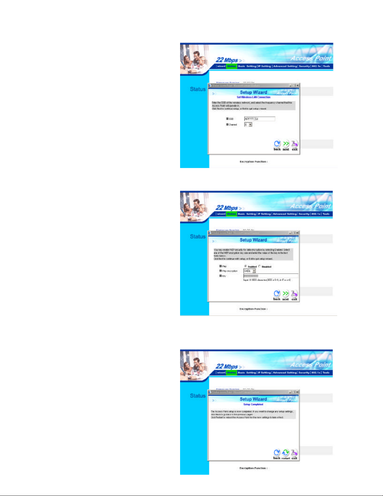
Step 2: Set WLAN Connection
Enter the SSID that you would like to
use and select the channel of
operation, then click “Next” to
continue.
Step 3: Set WEP Encryption
You may enable the WEP security by
selecting “
simply click “Next” to continue
Select one of the WEP encryption
Enabled
”, otherwise,
key size and enter the value of the
key in the Key text box, then click
“Next” to continue.
Note! There are 3 key sizes to choose
from, 64, 128 and 256 Bit, however
256 Bit will only be supported with
22Mbps series products.
Step 4: Restart
The Setup wizard is now completed.
The new settings will be effective
after the Access Point restarts.
Click “
Point.
Restart
” to reboot the Access
-13-
Page 14

The Access Point is now rebooting,
click “
wizard window and go back to the
main menu.
” to close the Setup
Close
Status Page
This page displays the following information.
-14-
Page 15

Firmware Version: Shows the current firmware version
Shows the Mac address, IP address (default: 192.168.1.1), Subnet Mask, Gateway Address.
LAN:
The current LAN traffic calculated in terms of number of packets sent and received by AP through
wired connection is also displayed.
Wireless: Shows the Mac address, current ESSID, the status of Encryption Function (Enable or
Disable), the current using channel. The current wireless traffic calculated in terms of number of
packets sent and received by AP through wireless communication is also displayed.
View Log:
the time that it happens.
Upon clicked, the page will change to log page. The log page records every event and
You may clear the entries recorded in the log by clicking the “
screen to show the latest log entries by clicking the “Refresh” button.
Clear Log
” but ton, and refresh the
-15-
Page 16

Basic Setting
This is the page where you can change the basic settings of the Access Point with the minimum
amount of effort to adjust a secure wireless network.
AP Name: Name of the AP, which can be used to identify the Access Point among the all the
Access Points in the wireless network.
SSID: Service Set Identifier, which is a unique name shared among all clients and nodes in a
wireless network. The SSID must be identical for each clients and nodes in the wireless network.
Channel: The value of channel that AP will operate in. You can select the channel range of 1 to 11
for North America (FCC) domain, 1 to 13 for European (ETSI) domain and 1 to 14 for Japanese
domain.
WEP Key:
are 3 type of WEP keys to choose from, 64bits, 128bits and 256bits. When one of the 3 WEP key
options is selected, you must enter the value of one of the four Keys in ASCII or HEX format. You
can also enter the values for all four WEP keys, and select one to use.
Note!
Access Point must also have WEP enabled with the identical WEP Key value entered.
For the changes made to any of the items above to be effective, click “Apply”.
To disable WEP security, click on the “Disable ” option. To enable WEP security, there
When AP’s WEP security is enabled, all the wireless clients that wish to connect to the
-16-
Page 17

The new settings are now been saved to Access Point and will be effective once the Access Point
restarts.
Click “
Back
” to go back to Basic Setting page.
-17-
Page 18

IP Setting
This is the page where you configure the IP and DHCP settings of the Access Point.
The default IP address of the Access Point is 192.168.1.1 with the Subnet Mask of 255.255.255.0.
You can type in other values for IP Address, Subnet Mask and Gateway and click “Apply” button
for the changes to be effective.
You can also set the Access Point to obtain the IP from a DHCP server, but it is not recommended.
Once set, it will be difficult to determine the dynamic IP assigned to the Access Point. Select the
option “Obtain IP Automatically” and click “
DHCP Server:
It’s not recommended to enable the DHCP Server if you have a DHCP server running in your LAN
network, for it will cause possible IP assignment conflict.
Enable the DHCP server function by selecting the option “On”, and enter the IP range.
Click “OK” to close pop -up box. Click “
Apply
” button for the changes to be effective.
Apply
” for the changes to be effective.
-18-
Page 19

The new settings are now been saved to Access Point and will be effective once the Access Point
restarts. Click “
” to go back to Basic Setting page.
Back
-19-
Page 20

Advanced Setting
This page contains configurations for advanced users, which the change will reflect the wireless
performance and operating modes.
AP Mode:
Select one of the AP operating modes for different application of Access Point.
1. AP – The normal Access Point operating mode which forms a wireless ESS network with its
wireless clients.
2. AP Client – Acts as an Ethernet-to-Wireless Bridge, which allows a LAN or a single computer
station to join a wireless ESS network through it. You must make sure that the SSID and
Channel is set to the same as that used by the AP you wish to connect.
Remote AP BSS ID
that you wish to get connected.
Please note that if you leave Mac address as 000000000000, then you will get connected
by the SSID that is set in you AP.
: key in the LAN Mac address (NOT wireless Mac address) of the AP
-20-
Page 21

3. Wireless Bridge – A pair of APs operating under Bridge mode to act as the bridge that connects
two Ethernet networks or Ethernet enabled clients together. You must make sure that the SSID
and Channel is set to the same as that used by the AP you wish to connect. The “Remote Bridge
MAC” is where you enter the MAC address of the other AP that you connect to setup the
wireless bridge.
Remote Bridge MAC filed
of the AP that you wish to get connected.
4. Multiple Bridge – A group of APs which consists of two or more APs operating under Multiple
Bridge mode, that can connect two or more Ethernet networks or Ethernet enabled clients
together. The way that multiple bridge setup is based on the topology of Ad-Hoc mode.
Note! All APs have to use the same Channel and SSID in order to form a Multiple Bridge network.
Beacon Interval: To set the period of time in milliseconds that AP sends out a beacon. Default is
100 milliseconds.
RTS Threshold:
To set the size of RTS/CTS packet size. Default is 2432 bytes.
: key in the
LAN Mac address
(NOT wireless Mac address)
Fragmentation Threshold
directed messages. Default is 2436 bytes.
DTIM Interval: This value indicates the interval of the Delivery Traffic Indication Message
(DTIM). A DTIM field is a countdown field informing clients of the next window for listening to
broadcast and multicast messages. When the Access Point has buffered broadcast or multicast
messages for associated clients, it sends the next DTIM with a DTIM Interval value. Access Point
Clients hear the beacons and awaken to receive the broadcast and multicast messages.
Authentication Type: The Authentication Type default is set to Open System, and you may want
to set to Shared Key when the clients and AP in the same wireless network enable the WEP
encryption. All the nodes and hosts on the network must use the same authentication type. It’s
recommend that you use the default setting.
Preamble Type:
circuitry to reach steady-state demodulation and synchronization of bit clock and frame start. Two
different preambles and headers are defined: the mandatory supported Long Preamble and header,
Preamble is a sequence of bits transmitted at 1Mbps that allows the PHY
: To set the number of bytes used for the fragmentation boundary for
which interoperates with the 1 Mbit/s and 2 Mbit/s DSSS specification (as described in IEEE Std
802.11), and an optional Short Preamble and header (as described in IEEE Std 802.11b). At the
receiver, the Preamble and header are processed to aid in demodulation and delivery of the PSDU.
The Short Preamble and header may be used to minimize overhead and, thus, maximize the network
-21-
Page 22

data throughput. However, the Short Preamble is supported only from the IEEE 802.11b (High-Rate)
standard and not from the original IEEE 802.11. That means that stations using Short-Preamble
cannot communicate with stations implementing the original version of the protocol.
Basic Rate: The basic transfer rate is set depending on the speed of your wireless network. For
example, you set 1-2 (Mbps) if you have older 802.11 compliant device in your network, which
supports 1 ~ 2 Mbps data rate. This setting does not limit the basic transfer rates of the faster
802.11 compliant network devices.
Antenna Selection:
Antenna, which is better for reception.
SSID Broadcast: While SSID Broadcast is enabled, all wireless clients will be able to
communicate with the Access Point. For security purpose, you may want to disable SSID
Broadcast to allow only those wireless clients with the AP’s SSID to communicate with the Access
Point.
4X Mode :
wireless transmission speed can achieve over 12Mbps real throughput assuming that the wireless
client device is also running 22Mbps PBCC+4X.
When “4X enable” is selected, you will be running 22Mbps PBCC+4X mode, the
To set the antenna for transmitting data. The default setting is Diversity
: 4X mode is proprietary transmission mode available only with our solution chipset. In
Note !
order to achieve superb speed by 4X or 22Mbps PBCC mode, both the transmitting and receiving
parties must be using our WLAN solution products.
-22-
Page 23

Security
This page is where you configure the security features supported by this Access Point.
Password:
Allow you to change the new login password. Here are the necessary steps:
1. Enter the new password in the “
2. Enter the new password again in the “Confirm” field.
3. Click “
Note! The wireless clients will not be able to recognize the Access Point using Site Survey utilities,
such as zero configuration utility provided in Windows XP.
Apply
”
AP Password New:
” field.
-23-
Page 24

MAC Filter
MAC Filter function controls the MAC of the network devices that are listed in this table for access
authorization or denial. When MAC Filter is enabled, by selecting the “Enabled” radio box, select
one of two choices:
Ø Only deny PCs with MAC listed below to access device, or
Ø Only allow PCs with MAC listed below to access device
The maximum number of MAC addresses that can be stored in Access Pint is 50. You can browse
through the MAC address saved by selecting the drop-down box.
-24-
Page 25

For any changes made in the security page, click “
above page will appear. Click “Back” to go back to the previous page.
” for the changes to be effective. When the
Apply
-25-
Page 26

802.1x
1 23 4
There are three essential components to the 802.1x infrastructure: (1) Supplicant, (2) Authenticator
and (3) Server. The Access Point serves as an Authenticator, and the EAP methods used must be
supported by the backend Radius Server. The 802.1x security supports both MD5 and TLS
Extensive Authentication Protocol (EAP). Please follow the steps below to configure 802.1x
security.
1. Enable 802.1x security by selecting “Enable ”.
2. If MD5 EAP method is used then you can skip step 2 and go to step 3.
3. Select the Encryption Key Length Size ranging from 64 to 256 Bits that you would like to use.
Select the Lifetime of the Encryption Key from 5 Minutes to 1 Day. As soon as the lifetime
of the Encryption Key is over, the Encryption Key will be renewed by the Radius server.
4. Enter the IP address of and the Port used by the Primary Radius Server
Enter the Shared Secret , which is used by the Radius Server.
5. Enter the IP address of, Port and Shared Secret used by the Secondary Radius Server.
-26-
Page 27

Click “Help” to get interpretation for Encryption Key and Radius Server
6. Click “Apply” button for the 802.1x settings to take effect after Access Point reboots itself.
Note! As soon as 802.1x security is enabled, all the wireless client stations that are connected to the
Access Point currently will be disconnected. The wireless clients must be configured manually to
authenticate themselves with the Radius server to be reconnected.
-27-
Page 28
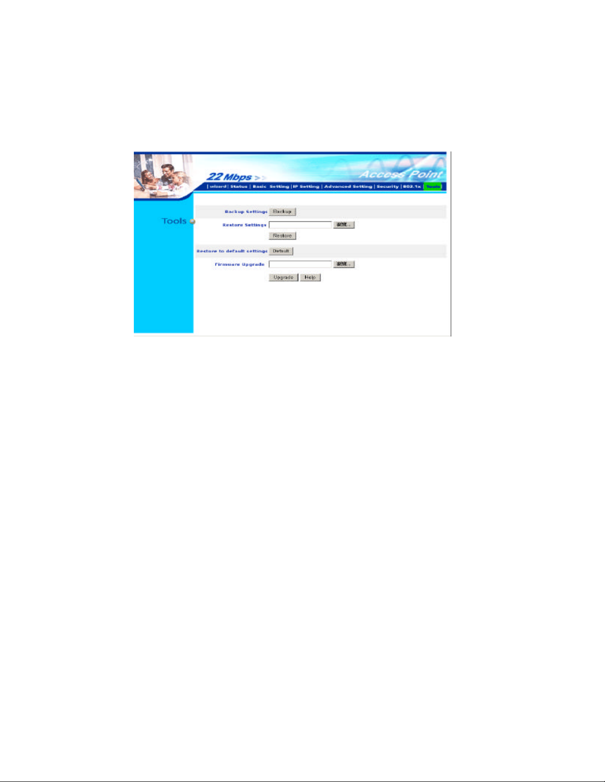
Tools
Three functions are provided in this page, Backup/Restore Settings, Restore default settings and
Firmware Upgrade.
Backup Settings:
Click on “
current settings and configurations to a file.
Restore Settings:
Click on the “
which you save previous settings and configurations, to be opened.
Upon selecting the saved file, click “
Point re -operates after it restarts.
Restore to default settings:
Click on “
Firmware Upgrade:
Click on the “Browse” button to open a FileOpen Dialog box, where you get to select the firmware
file, which you download from the web for the latest version.
Backup
Default
” button, which will open a FileSave Dialog box, where you get to save all the
Browse
” button to open a FileOpen Dialog box, where you get to select the file,
Restore
” button to restore the Access Point back to it’s manufacture default settings.
” and complete the restore process when the Access
Upon selecting the firmware file, click “Upgrade” and complete the firmware upgrade process
when the Access Point re -operates after it restarts.
-28-
Page 29

USING AP 22M UTILITY FOR MANAGEMENT
Installing AP 22M Utility
The AP 22M Utility is a program that runs on your PC, which offers easy management for all
existing 22mbps Access Points in the same network domain. Please follow the steps below for
installation and refer to “Manage and Configure AP with AP 22M Utility” ses sion Access point
configuration .
Note! The installation demonstrated is based on Windows XP operating system. The other
Windows operation system will have very similar installation.
1. Turn on your PC
2. After Windows starts up, insert the 22Mbps Access Point Product CD into the CD tray of the
CD-ROM
3. The following screen would appear.
-29-
Page 30

4. Select menu option, “Access Point”, on the left side of screen.
5. Click “Install ” on the menu bar to proceed with 22M AP installation.
-30-
Page 31

6. The 22M AP Utility loads the Install wizard for installation.
Click “Next” to start
installation.
Click “Next” to
install in default
folder or Click
“Browse” to install
in a different folder.
-31-
Page 32

Installation wizard copies the utility program files in your PC.
7. Click “Finish” to complete the installation.
-32-
Page 33

8. The 22M AP Utility icon would then appear on your desktop for easy access.
Manage and Configure Access Point with 22M AP Utility
The AP 22M Utility can be useful in a way that allows you to configure one AP to another to save
the trouble of logging into the web configuration utility of each AP. However, all the Access Points
that you wish to configure using 22M AP Utility must be in the same network domain as your PC’s.
You may also check the existence with the Access Point by pinging the IP of the Access Point, for
example, 192.168.1.1, in the command prompt window.
-33-
Page 34

Link Information
This is the default page when 22M AP Utility starts up.
– displays the basic settings of the selected Access Point.
Status
Available AP
network. You can select a particular Access Point from the list to view and change its
configuration.
– lists all the 22mpbs Access Point of the same network domain detected on the
-34-
Page 35

AP Settings
1 23
1
23
This is the page that allows you to change the settings of the Access Point.
Basic Setting – allows you to enter the new values for ESSID, Channel and AP
Name of the Access Point.
Mode Setting – allows you to change the operating mode of the Access Point.
There are 4 modes that you can choose: (1) Access Point, (2) Access Point
Client, (3) Wireless Bridge and (4) Multiple Bridge. Please refer to Appendix
C, Glossary for the functionalities and definitions of these operating modes.
Advanced Setting – recommended for advanced users who are familiar with
wireless networks, and it ’s where you set additional parameters and settings of
the Access Point.
-35-
Page 36

4X Mode : When “4X enable” is selected, you will be running 22Mbps PBCC+4X mode, the
wirel ess transmission speed can achieve over 12Mbps real throughput assuming that the wireless
client device is also running 22Mbps PBCC+4X.
Note !: 4X mode is proprietary transmission mode available only with our solution chipset. In
order to achieve superb speed by 4X or 22Mbps PBCC mode, both the transmitting and receiving
parties must be using our WLAN solution products.
Please refer to Appendix C, Glossary for the definitions of other values and function.
-36-
Page 37

For any changes made to be effective, click “Apply” button.
The utility program will now prompt you for user name and password as part of the login and
security protection to make sure you have the right
authorization.
Enter “UserName”
and “Password” for
the Access Point
Click “OK” button
Note!
default password is also “admin”.
The Access Point
restarts itself, and
the screen wi ll
switch back to
startup page – Link
Information
The default username is “admin” and the
-37-
Page 38

IP Settings
This is the page where you configure the IP settings for the Access Point.
Select “Fixed IP
Address” and enter
the IP address of the
Access Point and
Gateway.
Select “DHCP
Client” if there is a
DHCP server
assigning IP
addresses on the
network.
Please also refer to
Appendix B to learn
more about Network
and IP address.
Click “Apply” button for any changes made to be effective. The utility program will prompt you
for user name and password for security protection.
-38-
Page 39

WEP Settings
the 4 Web Key fields
This is the page that allows you to configure the WEP settings for the Access Point.
Enable WEP Key
security by clicking
“Data Encryption”
Select the “Auth.
Mode ” and the
“Key Length”
Fill at least one of
with Hex or ASCII
values.
-39-
Page 40

802.1x Settings
1. Enable 802.1x security by clicking the “802.1X Function” checkbox.
2. If
3. Select the Encryption Key Lifetime from 5 Minutes to 1 Day. As soon as the lifetime of the
Encryption Key is over, the Encryption Key will be renewed by the Radius server.
4. Select the Length ranging from 64 to 256 Bits that you would like to use for Encryption Key
Length.
5. RADIUS Server 1: Enter the IP address of and the Port used by the Primary Radius Server
Enter the
6. RADIUS Server 2: Enter the IP address of, Port and Shared Secret used by the Secondary
Radius Server.
7. Click “Apply” button for the 802.1x settings to take effect after Access Point reboots itself.
Note! As soon as 802.1x security is enabled, all the wireless client stations that are connected to the
Access Point currently will be disconnected. The wireless clients must be configured manually to
EAP methods is used then you can skip step 3 and go to step 4.
MD5
Shared Secret
, which is used by the Radius Server.
authenticate themselves with the Radius server to be reconnected. Please refer to Appendix C for
detail 802.1x setup and installation.
-40-
Page 41

APPENDIX A: TROUBLESHOOTING
This chapter provides solutions to frequently encountered problems that can occur during the
installation and operation of the Wireless Access Point. Please read through the following to solve
your problems.
1. The computer connected to the Wireless Access Point through Ethernet network cannot
access the configuration menu.
Ø Check that the Ethernet Adapter is working properly. Make sure that the drivers for the
network adapters are installed properly.
Ø Check that the Ethernet cable is connect to the Wireless Access Point properly, and the
Ethernet LED of the Wireless Access Point is ON.
Ø Check that the IP address of the computer is in the same IP range and subnet as that of the
Wireless Access Point. Please refer to the Networking Basis in APPENDIX B in this
manual for more information if necessary.
Note! The default IP Address of the Wireless Access Point is 192.168.1.1. All the computers on the
network must have a unique IP address in the same range, e.g., 192.168.1.xxx, and they must all
have the same subnet mask, e.g., 255.255.255.0.
Ø Check the connection of computer and Wireless Access Point by doing a simple Ping test.
Ø Go to Start>Run>Type “command”> Type “ping 192.168.1.1 ”. A successful ping will
show responses from the Wireless Access Point.
-41-
Page 42

2. The wireless clients cannot access the network in the infrastructure mode.
Ø Check that the wireless network device is being installed and working properly.
Go to “Start” >
Right mouse click
on “My Computer”
> “Properties”
Go to “Hardware”
-42-
Page 43

Go to “Device
Manager ”
Right mouse click
on the network
adapter which you
connect RJ45 cable
with. And go to
“Properties”
-43-
Page 44

Check and make
sure that the network
adapter is working
properly
3. Resetting the Wireless Access Point to Factory Default Setting.
You may choose to Reset the Wireless Access Point by doing the following:
Ø Locate the Reset button on the back of the Wireless Access Point
Ø Use a paper clip to press the Reset button
Ø Hold the reset button for at least 5 seconds before you release
Ø Wait till the Wireless Access Point reboots itself (it may take a few minutes), then the
configura tion will be set back to factory default values.
4. What are the operation modes supported by the Wireless Access Point?
The Wireless Access Point supports 4 operation modes:
- Access Point:
Forms a wireless network and works as a bridge to communicate with Ethernet LAN network.
- AP Client:
Acts as an wireless client which allows the computers that are connected to the AP to
communicate with other wireless clients.
- Point-to-Point Bridge:
Connects two independent Ethernet LAN networks or computers wirelessly.
- Multi -point Bridge:
Connects more than two independent Ethernet LAN networks or computers wirelessly.
-44-
Page 45

5. What is the difference between 22mbps and 11mbps wireless products? What’s the
benefit of 22mbps Wireless Access Point?
The 22mbps is made possible by the new modulation method called PBCC developed by TI,
which is different from the current CCK modulation method for 11mbps. The 22mbps Wireless
Access Point offers double data rate than that of 11mbps with 20% more distance coverage. The
22mbps wireless products also operate in the 2.4GHz ISM band and they are backward
compatible with 11mbps wireless products.
6. What is Roaming?
Roaming is the ability of portable computers, e.g., Packet PC and notebook, to have consistent
and continuous data transmission/rec eption throughout an area covered by more than one
Wireless Access Point. In order to achieve seamless connectivity, all the wireless clients and
Access Points must be set to use the same SSID. When a user walked out of the coverage area
of one AP into a nother, the wireless client network device will automatically reestablish
connection with the new AP.
7. What is a MAC Address?
The Media Access Control (MAC) address is a unique number assigned by the manufacturer to
any Ethernet networking devices, e.g. a network adapter, that allows the network to identify it at
the hardware level. Unlike IP addresses, which can be changed or dynamically assigned by
the network, the MAC address of a networking device is permanent.
8. What is WEP?
Wired Equivalent Privacy (WEP) is a type of data encryption mechanism described in the IEEE
802.11 standard. The 22mbps Wireless Access Point supports 64/128/256 bit shared key for
WEP.
9. Would the information be transmitted securely in the air?
WLAN offers two layers of protection for security. First layer is on the hardware level. As
with Direct Sequence Spread Spectrum (DSSS) technology, it has the inherent security feature
of scrambling. Second of all, on the software level, the security control is made possible by
Wired Equivalent Privacy (WEP) for access control.
10. What is ISM band?
The FCC and their counterparts outside of the U.S. have set aside bandwidth for unlicensed use
in the ISM (Industrial, Scientific and Medical) band. The 2.4GHz unlicensed ISM band is
available worldw ide, which presents the opportunity for the global market of 802.11b high
speed wireless products.
11. What is 4X mode?
-45-
Page 46

This is a proprietary wireless data transmission mode provided by TI, which enhances TI’s
22Mbps PBCC speed to reach data throughput to over 12Mbps. Since it is not IEEE 802.11b
standard wireless data mode, in order to allow 4X mode, both the receiving and transmitting
parties must be using TI solution.
-46-
Page 47

APPENDIX B: NETWORKING BASIS
This chapter will help you learn the basics of home networking.
Using the Windows XP Network Setup Wizard
Go to Start menu >
Control Panel >
Network Connections
In the menu on the left
side of the window,
select “Set up a home
or small office
network ”
Click “Next” to
procced
Click “Next” to
continue
-47-
Page 48

Select the option
that best describes
how you connect
your computer to the
Internet.
In the case of using
router in the
network, choose the
second option.
Click “Next” to
continue.
1. Enter a short
description for your
computer.
2. Enter a name for
your computer to be
recognized among
th e network.
3. Click “Next” to
continue.
-48-
Page 49

Enter “Workgroup
name ” for your
home network.
Click “Next” to
continue”
Click “Next” and
wait for the wizard
to apply the settings.
-49-
Page 50

floppy disk into your
You may create a
network setup disk
which saves you the
trouble of having to
configure every PCs
in your network.
Select the first
choice, and insert a
disk drive
Click “Next” to
continue.
-50-
Page 51

Click “Format
Disk” if you wish to
format the disk.
Click “Next” to
copy the necessary
files to the disk.
Click “Next” to
continue with the
Network Setup
Wizard
-51-
Page 52

Note! Now you may use the Network Setup Disk you just created in any PCs in your network that
you wish to setup. Simply insert the Network Setup Disk into the disk drive of a PC, and open to
browse the content of the disk with “My Computer” or “Windows File Manager”. Double -click
and run the file “netsetup” for the program to handle the rest.
Click “Finish” to
complete the
Network Setup
Wizard.
System will now
have to restart in
order for the new
settings to be
effective.
Click “Yes” to
restart the computer
-52-
Page 53

Checking IP Address of Your Computer In Windows XP
Sometimes you will need to know the IP address of the computer that you are using. For example,
when you want to make sure that your computer is in the same network domain as that of your
Access Point for you can configure and access the AP.
Go to Start menu >
Run > type
“command”
Click “OK”
When the command prompt window appears, type command “ipconfig /all ” and press Enter. This
command will display the IP addresses of all the network adapters in your computer.
In this case, the IP address of your network adapter is 192.168.1.2 hich means your Access Point
must have an IP address of 192.168.1xxx in order for you to be able to access it.
-53-
Page 54

If the IP address is assigned by DHCP server on the network, there are chances you might have to
release the IP and acquire it from DHCP server again. Here is how you do it.
Go to Start menu >
Run > type
“command”
Click “OK”
Type command, “ipconfig /renew” in the command prompt window and press Enter. This
command releases the current IP address and acquire it from the network, i.e. DHCP server, once
more.
In this case, the IP address that we acquired is 192.168. 1.3. However, it ’s often that the acquired IP
address of the network adapter might would not be the same.
To renew IP under Windows 98 and Windows ME, you will have to go to the
Note!
Run > type winipcfg and click “OK”. The Windows IP Configuration Menu window would
appear, where you first click “release” button to release the current IP address, followed by clicking
of “Renew” to acquire a new IP address from network.
If the above methods for IP renew fail, you will have to try and restart the computer, which will
reinitializes the network adapter settings during startup including renewing IP address. If you still
have problems getting an IP address after computer restarts, you will have to consult with your MIS
in your office or call computer and network technicians.
Start
menu >
-54-
Page 55

Dynamic IP Address V.S. Static IP Address
By definition Dynamic IP addresses are the IP addresses that are being automatically assigned to a
network device on the network. These Dynamically assigned IP addresses will expire and may be
changed over time.
Static IP addresses are the IP addresses that users manually enter for each of the network adapters.
Go to Start menu > Control
Panel > Network
Connections > Right -click on
the active Local Area
connection > Select
“Properties”
Note! There might be two or more Local Area Connection to choose from. You must select the one
that you will use to connect to the network.
-55-
Page 56

The Local Area Connection
Properties would appear.
Select “Internet Protocol
(TCP/IP)” and Click
“Properties” to continue.
Dynamically Assigned IP Address
The TCP/IP Properties window
appears.
Select “Obtain an IP address
automatically” if you are on a
DHCP enabled network.
Click “OK” to close the window
with the changes made
-56-
Page 57

Static IP Address
Select “Use the following IP
address ”
Enter the IP address and subnet
mask fields.
Enter the IP address of the Router
in the Default gateway field.
Enter the IP address of the Router
in the DNS server field
Click “Ok” to close the window
Note!
The IP address must be within the same range as the wireless route or Access Point.
Wireless Network in Windows 2000
Go to Start menu > Settings >
Netw ork and Dial-up
Connections > Double-click on
the Local Area Connection
Select “Internet Protocol
(TCP/IP)” and click
“Properties”
22Mbps WLAN Adapter
-57-
Page 58

The TCP/IP Properties window
appears.
Select “Obtain an IP address
automatically” if you are on a
DHCP enabled network.
Click “OK” to close the window
with the changes made
Select “Use the following IP
address ”
Enter the IP address and subnet
mask fields.
Enter the IP address of the Router
in the Default gateway field.
Enter the IP address of the Router
in the DNS server field
Click “Ok” to close the window
-58-
Page 59

Wireless Network In Windows 98 and Windows ME
Go to Start menu > Settings >
Control Panel > Double-click on
Network
Select TCP/IP of the network
device
Click “Properties” to continue
The Access Point
restarts itself, and
the screen will
switch back to
startup page – Link
Information
The TCP/IP Properties window
appears.
Select “Obtain an IP address
automatically” if you are on a
DHCP enabled network.
Click “OK” to close the window
with the changes made
-59-
Page 60

Select “Specify an IP address”
Enter the IP address and subnet
mask fields.
In the DNS Configuration Tab
Page, (1) enter the IP address of
the Router in the Default
gateway field.
(2) Enter the IP address of the
Router in the DNS server field
-60-
Page 61

APPENDIX C: 802.1x Authentication Setup
There are three essential components to the 802.1x infrastructure: (1) Supplicant, (2) Authenticator
and (3) Server. The 802.1x security supports both MD5 and TLS Extensive Authentication
Protocol (EAP). The 802.1x Authentication is a complement to the current WEP encryption used
in wireless network. The current security weakness of WEP encryption is that there is no key
management and no limitation for the duration of key lifetime. 802.1x Authentication offers key
management, which includes key per user and key per session, and limits the lifetime of the keys to
certain duration. Thus, key decryption by unauthorized attacker becomes extremely difficult, and
the wireless network is safely secured. We will introduce the 802.1x Authentication infrastructure
as a whole and going into details of the setup for each essential component in 802.1x authentication.
802.1x Authentication Infrastructure
The Infrastructure diagram showing above illustrates that a group of 802.11 wireless clients is
trying to form a 802.11 wireless network with the Access Point in order to have access to the
Internet/Intranet. In 802.1x authentication infrastructure, each of these wireless clients would have
to be authenticated by the Radius server, which would grant the authorized client and notified the
Access Point to open up a communication port to be used for the granted client. There are 2
Extensive Authentication Protocol (EAP) methods supported: (1) MD5 and (2) TLS.
MD5 authentication is simply a validation of existing user account and password that is stored in the
server with what are keyed in by the user. Therefore, wireless client user will be prompted for
account/password validation every time when he/she is trying to get connected. TLS authentication
-61-
Page 62

is a more complicated authentication, which involves using certificate that is issued by the Radius
server, for authentication. TLS authentication is a more secure authentication, since not only the
Radius server authenticates the wireless client, but also the client can validate the Radius server by
the certificate that it issues. The authentic ation request from wireless clients and reply by the Radius
Server and Access Point process can be briefed as follows:
1. The client sends an EAP start message to the Access Point
2. The Access Point replies with an EAP Request ID message
3. The client sends its Network Access Identifier (NAI) – its user name – to the Access Point
in an EAP Respond message.
4. The Access Point forwards the NAI to the RADIUS server with a RADIUS Access
Request message.
5. The RADIUS server responds to the client with its digital certificate.
6. The client validates the digital certificate, and replies its own digital certificate to the
RADIUS server.
7. The RADIUS server validates client’s digital certificate.
8. The client and RADIUS server derive encryption keys.
9. The RADIUS server sends the access point a RADIUS ACCEPT message, including the
client’s WEP key.
10. The Access Point sends the client an EAP Success message along with the broadcast key
and key length, all encrypted with the client’s WEP key.
Supplicant: Wireless Network PC Card
Here is the setup for the Wireless Network PC Card under Windows XP, which is the only
Operating System that our driver supports for 802.1x. Microsoft is planning on supporting 802.1x
security in all common Windows Operating System including Win98SE/ME/2000 by rele asing
Service Pack in 2003.
Please note that the setup illustration is based on our 22Mbps wireless PC Card.
1. Go to Start > Control Panel
2. double-click on “
3. right-click on the Wireless Network Connection that you use with our 22Mbps wireless PC
Card.
Network Connections
”
-62-
Page 63

4. Click “Properties” to open up the Properties setting window.
5. Click on the “
Wireless Network
” tab.
-63-
Page 64

6. Click “Properties” of the available wireless network, which you wish to connect or configure.
Please note that if you are going to change to a different 802.1x authentication EAP method,
i.e. switch from using MD5 to TLS, , you must remove the current existing wireless network
from your Preferred networks first, and add it in again.
To configure for using TLS authentication method, please follow steps 7 ~ 25.
Please follow steps 26 ~ for using MD5 authentication method.
-64-
Page 65

TLS Authentication
7. Select “The key is provided for me automatically” option
8. Click “OK” to close the Wireless Network Properties window.
9. Click “Authentication” tab
10. Select “
authentication.
Enable network access control using IEEE 802.1x
” option to enable 802.1x
-65-
Page 66

11. Select “Smart Card or other Certificate” from the drop-down list box for EAP type.
12. Click “OK” to close the Wireless Network Connection Properties window, thus make the
changes effective.
The wireless client configuration in the zero-configuration utility provided in Windows XP is now
completed for TLS configuration. Before you can enable IEEE 802.1x authentication and have
wireless client authenticated by the Radius server, you have to download the certificate to your local
computer first.
-66-
Page 67

TLS Authentication – Download Digital Certificate from Server
In most corporation s, it requires internal IT or MIS staff’s help to have the certificated
downloaded to your local computer. One of the main reasons is that each corporation uses its
own server systems, and you will need the assistance from your IT or MIS for account/passw ord,
CA server location and etc. The following illustration is based on obtaining a certificate from
Windows 2000 Server which can act as a CA server, assuming you have a valid
account/password to access the server.
13. Connect to the server and ask for access, and the server will prompt you to enter your user
name and password.
14. Enter your
user name
and
password
, then click “OK” to continue.
Please note that we use IP addresses for connection with the server for our illustration, and the
IP of the server is 192.168.1.10.
15. After successful login, open up your Internet Browser, and type the following in the
address field.
http://192.168.1.10/certsrv
This is how we connect to the Certificate Service installed in Windows 2000 server.
-67-
Page 68

16. Now we are connected to the Certificate Service. Select “Request a certificate”, and
click “
” to continue.
Next
-68-
Page 69

17. Select “User Certificate request”, and click “Next” to continue.
-69-
Page 70

18. Click “Submit >” to continue.
-70-
Page 71

19. The Certificate Service is now processing the certificate request.
-71-
Page 72

20. The certificate is issued by the server, click “Install this certificate” to download and store
the certificate to your local computer.
-72-
Page 73

21. Click “
” to store the certificate to your local computer.
Yes
-73-
Page 74

22. Certificate is now installed.
All the configuration and certificate download are now complete. Let’s try to connect to the Access
Point using 802.1x TLS Authentication.
-74-
Page 75

23. Windows XP will prompt you to select a certificate for wireless network connection. Click
on the network connection icon in the system tray to continue.
-75-
Page 76

24. Select the certificate that was issued by the server (WirelessCA), and click “OK” to
continue.
25. Check the server to make sure that it’s the server that issues certificate, and click “OK” to
complete the authentication process.
-76-
Page 77

MD5 Authentication
26. Select “Data encryption (WEP enabled)” option, but leave other option unselected.
27. Select the key format that you want to use to key in your Network key.
ASCII
HEX characters: 0~9, a~f
28. Select the
40 bits (5 characters for ASCII, 10 characters for HEX)
104 bits
29. After deciding the key format and key length that you wish to use for network key. Enter the
network key in “
characters: 0~9, a~z and A~Z
key length
(13 characters for ASCII, 26 characters for HEX)
that you wish to use
Network key
” text box.
Please note that that value of Network key entered, and key format/length used, must be the same
as that used in the Access Point. Although there are 4 set of keys can be set in the Access Point
WEP configuration, it’s the first set of key that must be the same as that we used by the supplicant
wireless client.
30. Click “OK” to close the Wireless Network Properties window, thus make the changes
effective.
-77-
Page 78

31. Select “Authentication” tab.
32. Select “
authentication.
33. Select “
Enable network access control using IEEE 802.1X
MD-5 Challenge
” from the drop-down list box for EAP type.
” to enable 802.1x
34. Click “OK” to close Wireless Network Connection Properties window, thus make all the
changes effective.
-78-
Page 79

Unlike TLS, which uses digital certificate for validation, the MD -5 Authentication is based on the
user account/password. Therefore, you must have a valid account used by the server for
validation.
35. WindowsXP will prompt you to enter your user name and password. Click on the network
connection icon in the system tray to continue.
-79-
Page 80

36. Enter the user name, password and the logon domain that your account belongs if you have
one or more network domain exist in your network.
37. Click “OK” to complete the validation process.
-80-
Page 81

Authenticator: Wireless Network Access Point
This is the web page configuration in the Access Point that we use.
1. Enable 802.1x security by selecting “
2. If MD5 EAP methods is used then you can skip step 3 and go to step 4.
3. Select the
Select the Lifetime of the Encryption Key from 5 Minutes to 1 Day. As soon as the lifetime
of the Encryption Key is over, the Encryption Key will be renewed by the Radius server.
4. Enter the IP address of and the Port used by the Primary Radius Server
Enter the
5. Enter the IP address of, Port and Shared Secret used by the Secondary Radius Server.
6. Click “
As soon as 802.1x security is enabled, all the wireless client stations that are connected to the
Note!
Access Point currently will be disconnected. The wireless clients must be configured manually to
authenticate themselves with the Radius server to be reconnected.
Encryption Key Length Size
Shared Secret
” button for the 802.1x settings to take effect after Access Point reboots itself.
Apply
, which is used by the Radius Server.
Enable
”.
ranging from 64 to 256 Bits that you would like to use.
-81-
Page 82

Radius Server: Window2000 Server
This section to help those who has Windows 2000 Server installed and wants to setup
Windows2000 Server for 802.1x authentication, which includes setting up Certificate Service for
TLS Authentication, and enable EAP-methods.
1. Login into your Windows 2000 Server as Administrator, or account that has Administrator
authority.
2. Go to
3. Click on “ Add/Remove Windows components”
4. Check “
>
Start
Control Panel
Certificate Services
, and double-click “Add or Remove Programs”
”, and click “Next” to continue.
-82-
Page 83

5. Select “Enterprise root CA”, and click “Next” to continue.
6. Enter the information that you want for your Certificate Service, and click “Next” to
continue.
-83-
Page 84

7. Go to Start > Program > Administrative Tools > Certificate Authority
8. Right -click on the “
9. Select “Certificate to Issue ”
Policy Setting
”, select “
new
”
10. Select “Authenticated Session” and “Smartcard Logon” by holding down to the Ctrl key,
and click “OK” to conti nue.
-84-
Page 85

11. Go to Start > Program > Administrative Tools > Active Directory Users and Computers .
12. Right -click on domain, and select ”
Properties
” to continue.
13. Select “Group Policy” tab and click “Properties” to continue.
-85-
Page 86

14. Go to “Computer Configuration” > “Security Settings” > “Public Key Policies”
15. Right -click “
16. Click “Automatic Certificate Request ...”
Automatic Certificate Request Setting
”, and select “
New
”
-86-
Page 87

17. The Automatic Certificate Requ est Setup Wizard will guide you through the Automatic
Certificate Request setup, simply click “
” through to the last step.
Next
18. Click “Finish” to complete the Automatic Certificate Request Setup
19. Go to Start > Run, and type “command” and click “Enter” to open Command Prompt.
20. Type “secedit/refreshpolicy machine_policy” to refresh policy.
Adding Internet Authentication Service
21. Go to Start > Control Panel > Add or Remove Programs
-87-
Page 88

22. Select “Add/Remove Windows Components” from the panel on the left.
23. Select “
Internet Authentication Service
”, and click “OK” to install.
-88-
Page 89

Setting Internet Authentication Service
24. Go to Start > Program > Administrative Tools > Internet Authentication Service
25. Right -click “
Client
”, and select “
New Client
”
-89-
Page 90

26. Enter the IP address of the Access Point in the Client address text field, a memorable
name for the Access Point in the
Access Point in the Shared secret text field. Re-type the password in the Confirmed
shared secret
27. Click “Finish” to complete adding of the Access Point.
text field.
Client-Vendor
text field, the access password used by the
-90-
Page 91

28. In the Internet Authentication Service, right-click “
29. Select “New Remote Access Policy”.
Remote Access Policies
”
30. Select “
Day-And-Time -Restriction
”, and click “
” to continue.
Add
-91-
Page 92

31. Unless you want to specify the active duration for 802.1x authentication, click “OK” to
accept to have 802.1x authentication enabled at all times.
32. Select “Grant remote access permission”, and click “Next” to continue.
-92-
Page 93

33. Click “Edit Profile” to open up
-93-
Page 94

For TLS Authentication Setup (Steps 34 ~ 38)
34. Select “Authentication” Tab
35. Enable “
Certificate” for TLS authentication
Extensible Authentication Protocol
”, and select “
Smart Card or other
-94-
Page 95

36. Go to Start > Program > Administrative Tools > Active Directory Users and Computers
37. Select “
who will be configured to have the right to obtain digital certificate remotely.
”, and double-click on the user that can be newly created or currently existing,
Users
Please note that in this case, we have a user called, test, whose account/password are used to obtain
the digital certificate from server.
-95-
Page 96

38. Go to the “Dial-in” tab, and check “Allow access” option for Remote Access Permission
and “
No Callback
” for Callback Options.
-96-
Page 97

For MD5 Authentication (Steps 39 ~ 54)
39. Go to Start > Program > Administrative Tools > Active Directory Users and Computers.
40. Right click on the domain, and select “
Properties
”
-97-
Page 98

41. Select “Group Policy” tab, and click “Edit” to edit the Group Policy.
-98-
Page 99

42. Go to “Computer Configuration” > “Windows Settings” > “Security Settings” > “Account
Policies” > “
Password Policies
”
43. Click “Define this policy setting”, select “ Enabled”, and click “OK” to continue.
-99-
Page 100

44. Go to Start > Program > Administrative Tools > Active Directory Users and Computers .
45. Go to
. Right -click on the user that you are granting access, and select “
Users
Properties
”
-100 -
 Loading...